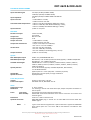
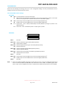
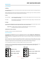
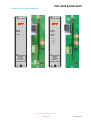
1
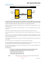
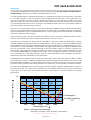
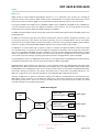
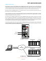
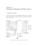
DDT-4620 & DDR-4620
3G/HD/SD-SDI/ASI Fibre Optic Link
User Manual
IRT Electronics Pty Ltd | www.irtelectronics.com
Revision 04
DDT-4620 & DDR-4620
3G/HD/SD-SDI/ASI FIBRE OPTIC LINK
Revision History:
Revision
00
Date
04/06/2010
By
AL
Change Description
01
04/01/2011
AL
02
20/04/2011
AL
Comment about “Keep Link Alive” added to General
Description and Configuration sections.
Reference to FP laser option removed.
03
16/08/2011
AL
Path loss specification updated.
04
30/05/2012
AL
Path loss specification updated. Reformatted layout.
Original Issue.
Applicable to:
Serial numbers
>1005001
Serial numbers
>1005001
Serial numbers
>1005001
Serial numbers
>1108001
Serial numbers
>1202001
IRT Electronics Pty Ltd | www.irtelectronics.com
Page 2 of 14
Revision 04
DDT-4620 & DDR-4620
USER MANUAL
Table of Contents:
Section
Page
Revision History
Operational Safety
General Description
Technical Specifications
Configuration
Installation
Signal Connections
Front and rear layouts
Operation
Figure 1: Attenuation versus wavelength
SNMP – What Is It?
DDT-4620 & DDR-4620 SNMP Functions
Maintenance & Storage
Warranty & Service
Equipment return
2
4
5
6
7
8
8
9
10
10
11
13
14
14
14
This instruction book applies to serial numbers > 1202001.
IRT Electronics Pty Ltd | www.irtelectronics.com
Page 3 of 14
Revision 04
DDT-4620 & DDR-4620
OPERATIONAL SAFETY
WARNING
Operation of electronic equipment involves the use of voltages and currents that
may be dangerous to human life. Note that under certain conditions dangerous
potentials may exist in some circuits when power controls are in the OFF position.
Maintenance personnel should observe all safety regulations.
Do not make any adjustments inside equipment with power ON unless proper
precautions are observed. All internal adjustments should only be made by suitably
qualified personnel. All operational adjustments are available externally without
the need for removing covers or use of extender cards.
Optical Safety
The light emitted from the LASER diode used in this system is
invisible and may be harmful to the human eye. Avoid looking
directly into the fibre optic cable or connectors or into the
collimated beam along their axis when the device is in operation.
Operating the LASER diode outside of its maximum ratings may
cause device failure or a safety hazard.
DANGER
Invisible LASER radiationAvoid direct exposure to beam
Peak power
Wavelength
2 mW
1270–1610nm
Class 1 LASER Product
IRT Electronics Pty Ltd | www.irtelectronics.com
Page 4 of 14
Revision 04
DDT-4620 & DDR-4620
GENERAL DESCRIPTION
BLOCK DIAGRAM DDT-4620 & DDR-4620 SIGNAL PATH
3G-SDI
HD-SDI
SD-SDI
ASI
DDT-4620
DDR-4620
I/P
Fibre O/P
O/P 1
O/P 2
Fibre I/P
SNMP
Fibre Link
*
9-27 dB path loss at 3G
(>30dB at HD and SD)
3G-SDI
HD-SDI
SD-SDI
ASI
SNMP
Alarm O/P
Alarm O/P
NOTE: * Fitted with APD detector. 3-18dB when fitted with PIN detector.
The IRT DDT-4620 and DDR-4620 are transmit and receive modules designed principally for use as a serial data
fibre optic transmission link for 3G-SDI, HD-SDI or SD-SDI applications conforming to SMPTE standards 424M, 292M
and 259M using 9/125 μm single mode fibre. This enables the use of space saving fibre optic cable for reliable
transmission of digital video signals over lengths greater than can be achieved with coaxial cable.
In addition, the link may be used for ASI transport streams for use with MPEG compressed video streams or other
270 Mb/s type data.
The transmitter features automatic input cable equalisation. The unit can be configured with lasers of various
wavelengths.
LED indicators are provided for digital signal presence, DC power and LASER output power out of range.
A link selectable “keep link alive” signal is available to maintain optical link operation when no electrical input is
present.
The receiver uses a choice of either a PIN photodiode or APD detector with signal conditioning and reclocking
circuits. The data rate is automatically set to match the 3G-SDI, HD-SDI or SD-SDI rates dependent on the actual
input data rate to the transmitter.
Two serial digital outputs are provided. LED indicators are provided for digital signal presence, signal type, optical
loss and power.
Relay contact outputs are also provided for external use of alarm signals on both modules.
An optional SNMP (Simple Network Management Protocol) plug-in module is available, for each unit, for remote
monitoring when used in conjunction with an IRT frame fitted with SNMP capability.
Both the DDT-4620 and DDR-4620 are Eurocard modules designed to fit IRT’s current range of 1RU 1000 series and
3RU 4000 series Eurocard frames.
Standard features:
•
•
•
•
•
NOTE:
One type covers 2.97 Gb/s 3G-SDI, 1.485 Gb/s HD-SDI or 270 Mb/s SD-SDI & ASI signals.
1
Path lengths up to 30 dB optical path loss using 9/125μm single mode fibre.
LED indicators and external alarm contacts.
Fibre, video and alarm connections at rear.
Optional plug-in SNMP monitoring module.
1
27dB path loss at 3G, > 30dB path loss at HD and SD. Fitted with APD detector.
IRT Electronics Pty Ltd | www.irtelectronics.com
Page 5 of 14
Revision 04
DDT-4620 & DDR-4620
TECHNICAL SPECIFICATIONS
DDT-4620:
Input serial data signal
Input impedance
Input return loss
Automatic Cable compensation
Input Connector
DDR-4620:
Number of outputs
Output level
Output impedance
Output return loss
Output Rise and Fall Time
Intrinsic Jitter
Output Connector
Optical:
DDT-4620 optical output
DDR-4620 optical input
2.97 Gb/s (3G-SDI) to SMPTE 424M;
1.485 Gb/s (HD-SDI) to SMPTE 292M;
270 Mb/s (SD-SDI) to SMPTE 259M and DVB-ASI.
75 Ω.
> 15 dB 5 MHz to 1.5 GHz;
> 10 dB 1.5 GHz to 2.97 GHz.
> 100 m at 2.97 Gb/s with Belden 1694A (typ. 130m);
> 100 m at 1.485 Gb/s with Belden 1694A (typ. 170m);
> 250 m at 270 Mb/s with Belden 8281 (typ. >300m).
1, BNC on rear panel.
2 data reclocked,
AC coupled.
800 mV ± 10%.
75 Ω.
> 15 dB 5 MHz to 1.5 GHz;
> 10 dB 1.5 GHz to 2.97 GHz.
< 135 ps at 2.97 Gb/s and 1.485 Gb/s;
> 0.4 ns and < 1.5 ns at 270 Mb/s.
< 0.3 UI at 2.97 Gb/s reclocked;
< 0.2 UI at 1.485 Gb/s reclocked;
< 0.2 UI at 270 Mb/s reclocked (typically < 0.1 UI).
2, BNC on rear assembly.
Optical fibre
Optical connectors
0 dBm +4.5/-0 dB CWDM DFB laser.
APD detector, -9 to -27 dBm input level at 3G-SDI, typically < -30 dBm at HD/SD-SDI.
PIN detector, -3 to -18 dBm input level.
CWDM DFB laser - 1270nm, 1290nm, 1310nm 1330nm, 1350nm, 1410nm,
1430nm, 1450nm, 1470nm, 1490nm, 1510nm, 1530nm, 1550nm, 1570nm,
1590nm & 1610nm.
9 to 27 dB at 3G-SDI, typically >30 dB at HD/SD-SDI, APD detector;
3 to 18 dB PIN detector.
(Optical path loss = Laser O/P power – Detector I/P power)
Designed for use with 9/125 μm single mode fibre.
SC/PC (standard).
Power Requirements:
Voltage
Power consumption
28 Vac CT (14-0-14) or ±16 Vdc.
DDT-4620 <4.0 VA, DDR-4620 <4.5 VA.
Available wavelengths
2
Optical path loss
Other:
Temperature range
Mechanical
Finish
Front panel
Rear assembly
Dimensions
Optional accessories
NOTE:
2
0 - 50° C ambient.
For mounting in IRT 19" rack chassis with input, output and power connections on
the rear panel.
Grey background, black lettering & red IRT logo.
Detachable silk-screened PCB with direct mount connectors to Eurocard and
external signals.
6 HP x 3 U x 220 mm IRT Eurocard.
SMU-4000 SNMP plug in module for use with 4000 series frame fitted with
SNMP “Agent”.
Typical values based using DFB laser. Optical attenuator supplied for DDR-4620
when optical path loss is less than 3dB for PIN detector and 9dB for APD
detector.
Due to our policy of continuing development, these specifications are subject to change without notice.
IRT Electronics Pty Ltd | www.irtelectronics.com
Page 6 of 14
Revision 04
DDT-4620 & DDR-4620
CONFIGURATION
Other than the following link settings, there are no user configurable settings. All other potentiometer and link
settings are factory set and should not be moved.
User link and DIP switch settings:
DDT-4620:
LK1
OUT Input equalization at maximum sensitivity.
IN
Reduces the input equalization sensitivity for use in noisy environments or when a short input
cable is used. Compensation limited to about 80 metres with Belden 1694A.
LK2
OUT Enable major and minor SNMP alarms to the frame Agent (CDM card) .
3
IN
Disable major and minor SNMP alarms to the frame Agent (CDM card) .
LK3
1-2
3
2-3
Enable Laser – laser is always enabled (keep link alive) whether input signal is present or not
(default position).
Auto Laser – laser is enabled only when an input signal is present.
DDR-4620:
DIP
SW1
ON
1 2 3 4 5 6 7 8
SW1-1
Not used.
SW1-2 OFF Output muted when signal absent (default position).
ON Output always enabled.
SW1-3 OFF Reclocker bypassed when signal not locked (default position).
ON Reclocker bypassed.
SW1-4 OFF Output amplitude standard 800mV (default position).
ON Output amplitude 1000mV.
SW1-5 OFF Output slew rate limited when 270 Mb/s signal (default position).
ON Output slew rate not limited.
SW1-6
Not used.
1
SW1-7 OFF Enable major and minor SNMP alarms to the frame Agent (CDM card) .
1
ON Disable major and minor SNMP alarms to the frame Agent (CDM card) .
SW1-8
Not used.
NOTE: 3 When using TRAPS via SNMP, depending on how system is set up, in order to avoid double reporting of
alarms via the DDT-4620 and DDR-4620 cards themselves and the CDM card (SNMP Agent) of the
frame, major and minor SNMP alarms that are reported to the CDM card of the frame can be disabled.
IRT Electronics Pty Ltd | www.irtelectronics.com
Page 7 of 14
Revision 04
DDT-4620 & DDR-4620
INSTALLATION
Pre-installation:
Handling:
This equipment may contain or be connected to static sensitive devices and proper static free handling precautions
should be observed.
Where individual circuit cards are stored, they should be placed in antistatic bags. Proper antistatic procedures
should be followed when inserting or removing cards from these bags.
Power:
AC mains supply:
Ensure that operating voltage of unit and local supply voltage match and that correct rating
fuse is installed for local supply.
DC supply:
Ensure that the correct polarity is observed and that DC supply voltage is maintained within
the operating range specified.
Earthing:
The earth path is dependent on the type of frame selected. In every case particular care should be taken to ensure
that the frame is connected to earth for safety reasons. See frame manual for details.
Signal earth: For safety reasons a connection is made between signal earth and chassis earth.
No attempt should be made to break this connection.
Installation in frame or chassis:
See details in separate manual for selected frame type.
Signal Connections:
The DDT-4620 and DDR-4620 are set up to automatically operate at either 2.97 Gb/s 3G, 1.485 Gb/s HD or
270 Mb/s SD signals and do not require any adjustment prior to use, with the exception of link and DIP switch
options described in the Configuration section of this manual. There are no external controls on the front panel of
the units.
Optical connections are made to the panel adapter mounted on a bracket at the rear of the modules. Care must be
taken to provide a clean surface on the optical connectors and in inserting the plug on the external fibre to prevent
damage to the alignment ferrule of the panel adapter. Type of fibre used must be single mode type.
The serial digital signal connections are made to the BNC connectors on the rear panels.
The external alarm contact connections are made to the 4 pin phoenix style connector at the bottom of the rear
assembly. On an alarm condition relay contacts go open circuit, that is switch open with respect to ground.
The connections being:
DDR-4620
DDT-4620
4
OPEN (not used)
4
OPEN (not used)
3
LASER FAIL / LASER OFF
3
OPTICAL LOW / OPTICAL LOSS
2
DIGITAL SIGNAL LOSS
2
DIGITAL SIGNAL LOSS
1
GND
1
GND
IRT Electronics Pty Ltd | www.irtelectronics.com
Page 8 of 14
Revision 04
DDT-4620 & DDR-4620
Front & rear panel connector diagrams:
D D T -462 0
DD R -462 0
SIGNAL
PRESENT
LOCKED
SIGNAL
LASER
OPTICAL
LOSS
3G
HD
SD
DC
DC
CAUTION
Direct
connections
to module
CAUTION
Direct
connections
to module
N140
N140
IRT Electronics Pty Ltd | www.irtelectronics.com
Page 9 of 14
Revision 04
DDT-4620 & DDR-4620
OPERATION
The DDT-4620 and DDR-4620 are automatically set up to operate at either 2.97 Gb/s 3G-SDI, 1.485 Gb/s HD-SDI or
270 Mb/s SD-SDI (or ASI) and do not require any adjustments prior to use.
A 2.97 Gb/s 3G-SDI signal or 1.485 Gb/s HD-SDI signal or a 270 Mb/s type of signal, such as ASI or SDI, is connected
to a 75 Ω BNC connector on the rear assembly of the DDT-4620 fibre optic transmitter. A front panel LED, and a
relay alarm accessible by the rear assembly, indicates the presence of a valid input signal. Likewise, front panel
LEDs, and a relay alarm also accessible by the rear assembly, indicates when the laser module is ON or either fails
or is automatically turned off on loss of input signal. Link settings set whether the laser is permanently enabled or
only enabled whilst a valid input signal is present.
If the laser is set for permanent operation, on loss of an input signal, a 54MHz oscillator is switched into the optical
output so that the DDR-4620 still recognizes the optical link as being valid. This 54MHz signal does not affect the
signal reclocking detect circuitry of the DDR-4620, which is used in signal presence/alarm indication on detection
or absence of a valid 3G, HD or SD signal.
Single mode optical cable is directly connected to the module at the rear of the unit. Likewise the fibre connection
at the far end of the fibre optic cable is directly connected to the rear of the receiver.
The system will operate with an optical path loss from 9dB to a maximum of 27dB (for 3G-SDI signals. Typically
>30dB for HD/SD-SDI signals) when fitted with an APD detector, and from 3dB to a maximum of 18dB when fitted
with a PIN detector. For path lengths <9dB optical loss when using an APD detector or <3dB optical loss when using
a PIN detector, an optical attenuator is recommended. The length of fibre that this corresponds to depends on the
fibre loss characteristics at the relevant wavelength of the laser module chosen. For example, if the fibre loss
characteristic of the chosen fibre is 0.2dB per kilometre at 1550 nm, say, then the maximum distance that can be
-1
run is 125 km (25dB/0.2dBkm ), although connector losses, such as through patch leads etc., should also be taken
into consideration when calculating maximum distances. Actual attenuation versus wavelength characteristics
depends upon optic fibre manufacturer’s own specifications.
The DDR-4620 receiver module accepts an input optical signal with a power level in the range of -9 dBm to -27 dBm
(for 3G-SDI signals. Typically <-30dBm for HD/SD-SDI signals) when fitted with an APD detector, and -3 dB to -18 dB
when fitted with a PIN detector. A red LED ‘Optical Loss’ indicator on the front panel, and a relay alarm accessible
by the rear assembly, indicates when the optical path loss is approaching, or has exceeded, the maximum allowed.
The output of the DDR-4620 receiver is the same signal that was originally inputted to the DDT-4620 transmitter. A
front panel green LED, and a relay alarm accessible by the rear assembly, indicates the presence of a valid locked
output signal. Three other green LEDs indicate whether the received signal is a 3G-SDI, an HD-SDI, or an SD-SDI
type of signal.
Attenuation (dB/km)
10
950
1240
1380
1
IR absorption
Rayleigh scattering
1/λ4
0.1
800
1000
1200
1400
Wavelength (nm)
1600
Figure 1: Attenuation versus wavelength.
Attenuation in the fibre is due to Absorption and Scattering.
IRT Electronics Pty Ltd | www.irtelectronics.com
Page 10 of 14
Revision 04
DDT-4620 & DDR-4620
SNMP
What Is It?
SNMP stands for Simple Network Management Protocol. It is an application layer protocol for managing IP
(Internet Protocol) based systems. SNMP enables system administrators to manage system performance, and to
find and solve system problems. SNMP runs over UDP (User Datagram Protocol), which in turn runs over IP.
Three types of SNMP exist: SNMP version 1 (SNMPv1), SNMP version 2 (SNMPv2) and SNMP version 3 (SNMPv3). It
is not the intention here to discuss the differences between various versions, only to bring attention to the fact
that IRT Electronics modules, fitted with SNMP capability, use SNMPv1.
An SNMP managed network consists of three key components: Network Management Systems (NMS), agents, and
managed devices.
An NMS is the console through which the network administrator performs network management functions, such
as monitoring status (e.g. alarm states) and remote controlling, of a set of managed devices. One or more NMS’s
must exist on any managed network. Generally the NMS is a computer running third party SNMP control software.
There are a number of third party SNMP software applications currently available on the market.
An NMS polls, or communicates with, an agent. An agent is a network management software module that resides
in a managed device. An agent has local knowledge of management information and translates that information
into a form compatible with SNMP. The agent, therefore, acts as an interface between the NMS and the managed
devices. The NMS sends a request message, and control commands for the managed devices, to the agent, which
in turn sends a response message, containing information about the managed devices, back to the NMS.
A managed device contains an SNMP agent and resides on a managed network. Managed devices collect and store
management information and make this information available to NMS’s using SNMP.
Managed device agent variables are organised in a tree structure known as a Management Information Base
(MIB). Within the MIB are parameters pertaining to the managed device. An Object Identifier (OID) number within
the MIB defines the managed device type. This is a unique number specific to the model of managed device. Other
information relating to the device is also stored, information such as alarm states, controllable settings, etc. The
MIB tree is organised in such a way that there will be no two MIB files with conflicting placements.
Normally an NMS polls an agent for information relating to the MIB in a managed device to be sent back to the
NMS. When certain conditions are met within the MIB, such as major alarm conditions, for example, the agent
automatically sends what is known as a trap to the NMS without any prompting from the NMS. This allows
automatic notification of a predetermined event.
SNMP Block Diagram
NMS
IP
Network
NMS
SNMP Agent
Protocol Engine
MIB
SNMP Agent
SNMP Agent
Protocol Engine
MIB
SNMP Agent
SNMP Agent
Protocol Engine
MIB
SNMP Agent
IRT Electronics Pty Ltd | www.irtelectronics.com
Page 11 of 14
Revision 04
DDT-4620 & DDR-4620
SNMP with IRT Products:
IRT Electronics currently employs SNMPv1 with its SNMP capable frames. The frame acts as an agent when fitted
with a CDM-xxxx module. This module has its own designated slot next to the power supply so as to not affect the
number of modules that the frame will take. Communication between the NMS, the frame and its loaded modules
are via this CDM-xxxx module. Note that the NMS software is third party and not supplied by IRT Electronics.
Ethernet connection for SNMP operation is via an RJ45 connector on the rear of the frame, below the mains inlet.
Ethernet rate runs at either 10 baseT or 100 baseT.
Frame parameters, such as Name, Address and Location, are set via an RS232 interface, a D9 connector on the rear
of the frame below the mains inlet. A software terminal emulator, such as Tera Term or HyperTerminal, is used for
setting and reading the parameters of the frame.
IRT modules that are SNMP compatible need a plug-in SMU-4000 module with a program relevant to the module
that it is plugged into. Depending on the module, besides the module identification, parameters such as alarm
states, inputs and controls etc. are communicated to the CDM-xxxx agent via a data bus on the rear of the frame.
Thus the CDM-xxxx collects information on what is loaded within the frame, what positions they occupy, and their
current status for communication to the NMS when the NMS sends a request for information.
In the event of a major alarm from any of the SNMP compatible modules, or power supplies, a trap is automatically
sent by the CDM-xxxx agent to the NMS without any prompting by the NMS. This alerts the operator to any fault
conditions that may exist that need immediate attention.
110/240 V 50/60 Hz
0.7 A (max.)
FRU-4000
FRAME
FUSES
220/240 Vac
500 mA S.B.
110/120 Vac
1A S.B.
RS232
Alarm
Ethernet
+
48Vdc
AS3260 approval no.: CS6346N
Ass. no.: 804692
IRT SNMP Connections
NMS
Ethernet Cable
IP
Network
IRT modules fitted
with SMU-4000
CDM-xxxx
PSU’s
IRT SNMP Frame
Ethernet Cable
IRT modules fitted
with SMU-4000
CDM-xxxx
PSU’s
IRT SNMP Frame
Ethernet Cable
IRT SNMP Setup
IRT Electronics Pty Ltd | www.irtelectronics.com
Page 12 of 14
Revision 04
DDT-4620 & DDR-4620
DDT-4620 & DDR-4620 SNMP Functions:
With the DDT-4620/DDR-4620 fitted with the optional plug-in SMU-4000 SNMP module, programmed to suit and
installed in an IRT frame with SNMP capability, these can be interrogated by an SNMP Network Management
System (NMS).
The following SNMP functions are capable of being monitored by an NMS:
DDT-4620:
irt4620Signal
irt4620Optical
irt4620Reset
irt4620AlarmSource
- An indication that an input signal is present,
[notPresent (1), present (2)].
- An indication that the laser is functioning correctly,
[LaserOkay (1), LaserFail (2)].
- Unit reset control. A set with a value of 2 sent to this OID will cause a system reset to
occur. When queried returns a 1.
4
- Set and read which conditions may cause Traps ,
[optical (1), signal (2), opticalAndSignal (3), none (4)].
NOTE: 4 Trap will be sent depending on setting of ‘irt4620AlarmSource’ field on ‘loss of’ parameter. For
example, loss of input signal when signal (2) setting is selected. Upon restoration of signal a Trap will
also be sent to indicate that alarm condition has cleared. With ‘irt4620AlarmSource’ field set to none
(4), Trap indication is disabled.
DDR-4620:
- An indication of signal presence and rate,
[noValidSignal (1), presentSD (2), presentHD (3), present3G (4)].
irt4620Optical
- An indication that that there is an optical input,
[noOpticalSignal (1), opticalSignalPresent (2)].
5
irt4620ReclockerBypass - Set and read the state of the Reclocker Bypass control,
[reclocking (1), bypassed (2)].
irt4620fpgaVersion
- The firmware version of the FPGA in the format ‘x.y’, where x is the major revision number
and y the minor.
irt4620snmpVersion
- The software version of the SMU in the format ‘x.y’, where x is the major revision number
and y the minor.
irt4620Reset
- Unit reset control. A set with a value of 2 sent to this OID will cause a system reset to
occur. When queried returns a 1.
irt4620AlarmSource
- An indication of alarm state conditions,
[none (1), optical (2), signal (3), opticalAndSignal (4)].
irt4620TrapEnable
- Enable or Disable Traps to be sent when the alarm source condition changes,
[notEnable (1), enabled (2)].
irt4620Signal
NOTE: 5 On board DIP switch SW1-3 ON (Reclocker Bypassed) position overrides the reclocking (1) SNMP set function.
IRT Electronics Pty Ltd | www.irtelectronics.com
Page 13 of 14
Revision 04
DDT-4620 & DDR-4620
MAINTENANCE & STORAGE
Maintenance:
No regular maintenance is required.
Care however should be taken to ensure that all connectors are kept clean and free from contamination of any
kind. This is especially important in fibre optic equipment where cleanliness of optical connections is critical to
performance.
Storage:
If the equipment is not to be used for an extended period, it is recommended the whole unit be placed in a sealed
plastic bag to prevent dust contamination. In areas of high humidity a suitably sized bag of silica gel should be
included to deter corrosion.
Where individual circuit cards are stored, they should be placed in antistatic bags. Proper antistatic procedures
should be followed when inserting or removing cards from these bags.
WARRANTY & SERVICE
Equipment is covered by a limited warranty period of three years from date of first delivery unless contrary
conditions apply under a particular contract of supply. For situations when “No Fault Found” for repairs, a
minimum charge of 1 hour’s labour, at IRT’s current labour charge rate, will apply, whether the equipment is
within the warranty period or not.
Equipment warranty is limited to faults attributable to defects in original design or manufacture. Warranty on
components shall be extended by IRT only to the extent obtainable from the component supplier.
Equipment return:
Before arranging service, ensure that the fault is in the unit to be serviced and not in associated equipment. If
possible, confirm this by substitution.
Before returning equipment contact should be made with IRT or your local agent to determine whether the
equipment can be serviced in the field or should be returned for repair.
The equipment should be properly packed for return observing antistatic procedures.
The following information should accompany the unit to be returned:
1.
2.
3.
4.
5.
6.
7.
A fault report should be included indicating the nature of the fault
The operating conditions under which the fault initially occurred.
Any additional information, which may be of assistance in fault location and remedy.
A contact name and telephone and fax numbers.
Details of payment method for items not covered by warranty.
Full return address.
For situations when “No Fault Found” for repairs, a minimum charge of 1 hour’s labour will apply,
whether the equipment is within the warranty period or not. Contact IRT for current hourly rate.
Please note that all freight charges are the responsibility of the customer.
The equipment should be returned to the agent who originally supplied the equipment or, where this is not
possible, to IRT directly. Details of IRT’s direct address can be found at IRT Electronics’ website.
Web address: www.irtelectronics.com
Email: [email protected]
IRT Electronics Pty Ltd | www.irtelectronics.com
Page 14 of 14
Revision 04