1
CITY OF BELLEVUE
UTILITIES DEPARTMENT
STORM AND SURFACE WATER
ENGINEERING STANDARDS
January 2015
http://www.bellevuewa.gov/utilities_codes_standards_intro.htm
SURFACE WATER ENGINEERING STANDARDS
JANUARY 2015
TABLE OF CONTENTS
CHAPTER D1 – GENERAL REQUIREMENTS
D1-01 GENERAL
D1-1
D1-02 DEFINITIONS
D1-1
D1-03 REFERENCES
D1-4
D1-04 GOVERNMENTAL AGENCY REQUIREMENTS
D1-5
CHAPTER D2 – THRESHOLDS AND PLAN SUBMITTAL
D2-01 GENERAL
D2-1
D2-02 ADJUSTMENTS AND DEVIATIONS
D2-1
D2-03 EXCEPTIONS
D2-2
D2-04 ERRORS AND OMISSIONS
D2-2
D2-05 THRESHOLDS
D2-2
D2-06 STORMWATER SITE PLANNING AND SUBMITTALS
D2-7
D2-07 PLAN FORMAT AND NOTES
D2-12
D2-08 AS-BUILT DOCUMENTATION
D2-19
D2-09 OPERATION AND MAINTENANCE MANUAL
D2-22
CHAPTER D3 - HYDROLOGIC ANALYSIS
D3-01 GENERAL
D3-1
D3-02 HYDROLOGIC MODELS
D3-1
D3-03 SUMMARY OF DESIGN FLOW
D3-14
D3-04 MINIMUM IMPERVIOUS AREAS
D3-15
D3-05 FLOW CONTROL EXEMPTIONS
D3-16
D3-06 SOIL TYPES
D3-16
SURFACE WATER ENGINEERING STANDARDS
JANUARY 2015
CHAPTER D4 - HYDRAULIC ANALYSIS & DESIGN
D4-01 GENERAL
D4-1
D4-02 OUTFALLS AND DISCHARGE LOCATIONS
D4-2
D4-03 OFF-SITE CAPACITY ANALYSIS
D4-5
D4-04 CONVEYANCE SYSTEMS
D4-6
D4-05 MANHOLES, CATCHBASINS AND INLETS
D4-67
D4-06 FLOW CONTROL
D4-70
D4-07 SETBACK REQUIREMENTS
D4-94
D4-08 EASEMENT REQUIREMENTS
D4-97
D4-09 PIPE COVERINGS AND ENCASEMENT
D4-99
CHAPTER D5 - WATER QUALITY BMPs
D5-01 GENERAL
D5-1
D5-02 SOURCE CONTROL BMPs
D5-1
D5-03 RUNOFF TREATMENT BMPS
D5-1
CHAPTER D6 – ON-SITE STORMWATER MANAGEMENT
D6-01 GENERAL
D6-1
D6-02 SITE SUITABILITY AND BMP SELECTION
D6-8
D6-03 DESIGN, SIZING, CONSTRUCTION AND MAINTENANCE
D6-12
D6-04 NDP MATERIALS
D6-54
SURFACE WATER ENGINEERING STANDARDS
JANUARY 2015
CHAPTER D7 – MATERIALS
D7-01 GENERAL
D7-1
D7-02 CONVEYANCE SYSTEMS
D7-1
D7-03 MANHOLES, CATCHBASINS, AND INLETS
D7-6
D7-04 FLOW CONTROL - DETENTION FACILITIES
D7-9
D7-05 FLOW CONTROL - INFILTRATION SYSTEMS
D7-13
CHAPTER D8 – METHODS OF CONSTRUCTION
D8-01 GENERAL
D8-1
D8-02 CLEARANCE BETWEEN UTILITY LINES
D8-1
D8-03 CONNECTIONS/MODIFICATIONS TO PUBLIC DRAINAGE SYSTEM
D8-1
D8-04 CONVEYANCE SYSTEMS
D8-2
D8-05 MANHOLES, CATCH BASINS, & INLETS
D8-4
D8-06 FLOW CONTROL - DETENTION FACILITIES
D8-5
D8-07 FLOW CONTROL - INFILTRATION SYSTEMS
D8-7
D8-08 ABANDONING FACILITIES
D8-7
D8-09 TESTING OF GRAVITY STORM DRAINS
D8-9
D8-10 TELEVISION INSPECTION
D8-11
D8-11 TESTING OF CONCRETE STRUCTURES
D8-11
D8-12 TRENCHLESS CONSTRUCTION
D8-13
D8-13 TRENCH EXCAVATION
D8-13
CHAPTER D9 – NATURAL SYSTEMS
D9-01 GENERAL
D9-1
D9-02 STREAMS
D9-1
D9-03 WETLANDS
D9-2
SURFACE WATER ENGINEERING STANDARDS
JANUARY 2015
APPENDICES
APPENDIX D-1
STANDARD DETAILS
A(D1-1)
APPENDIX D-2
DRAFTING STANDARDS
A(D2-1)
APPENDIX D-3
SAMPLE TITLE BLOCK
A(D3-1)
APPENDIX D-4
SURFACE WATER APPROVED MATERIALS LIST
A(D4-1)
APPENDIX D-5
SURFACE WATER REFERENCE STANDARDS
A(D5-1)
CHAPTER D1 – GENERAL REQUIREMENTS
TABLE OF CONTENTS
Dl-01
GENERAL ................................................................................................................. D1-1
D1-01.1
Purpose............................................................................................................... D1-1
Dl-02
DEFINITIONS ........................................................................................................... D1-1
Dl-03
REFERENCES ........................................................................................................... D1-5
Dl-04
GOVERNMENTAL AGENCY REQUIREMENTS ................................................. D1-6
SURFACE WATER ENGINEERING STANDARDS
JANUARY 2015
CHAPTER D1 - GENERAL REQUIREMENTS
Dl-01 GENERAL
D1-01.1
Purpose
These Engineering Standards set forth the minimum standards for the planning, design,
and construction of storm and surface water systems.
The Storm and Surface Water Utility Code, Chapter 24.06 of the Bellevue City Code,
adopted by Ordinance 5905 on October 5, 2009, is the basis for these engineering
standards.
Although these standards are intended to apply to physical development within the City,
the standards will not apply for all situations. Compliance with these standards does not
relieve the Developer of the responsibility to apply conservative and sound professional
judgment. These are minimum standards and are intended to assist, but not substitute for
competent work by design professionals. The Utility may, at its sole discretion due to
special conditions and/or environmental constraints, require more stringent requirements
than would normally be required under these standards.
Dl-02 DEFINITIONS
The following terms as used in this document shall be defined and interpreted below.
Other terms used in the Standards are defined and interpreted in the “Storm and Surface
Water Utility Code” BCC 24.06.040 and the “Clearing and Grading Code”
BCC 23.76.030.
“BMP”
Best Management Practice
"Contractor"
The person, partnership, firm or corporation contracting to do the work under these
Documents. The term shall also include the Contractor's agents, employees and
subcontractors.
"Details or Additional Drawings"
All details or drawings prepared to further explain or amplify the Plans, or for the
revision of the same, all as herein provided.
“Developer”
Any individual, company, partnership, joint venture, corporation, association, society or
group that has made, or intends to make, application to the City for permission to
construct a surface water system connection, or extension, to the surface water system.
“DOE Manual”
“Stormwater Management Manual for Western Washington,” Washington State
Department of Ecology, February 2005. When referenced, drainage systems shall
D1-1
SURFACE WATER ENGINEERING STANDARDS
JANUARY 2015
conform to the criteria set forth in the DOE Manual. Such criteria, unless modified
herein, shall be the minimum standard which surface water systems must meet.
“Engineer”
The City of Bellevue Utilities Assistant Director for Engineering, or his or her duly
authorized assistants, which includes, Engineering managers & staff, Consulting
Engineers and/or Inspectors.
“Equipment”
The machinery, accessories, appurtenances and manufactured articles to be furnished
and/or installed under the Project.
“Flooding”
The term “flooding” as used in the Storm Code Chapter 24.06.065 G 5 shall mean any
natural or human caused event that endangers the safety of the public through water
entering a structure inhabited by the public.
“Flow Control Credit”
Credit toward reducing the size of downstream flow control facility(ies) through the use
of on-site stormwater management.
“Infiltration BMP or NDP”
A natural drainage practice that infiltrates stormwater without an underdrain, resulting in
all runoff being infiltrated or lost to evapotranspiration. These facilities are distinguished
from ‘partial infiltration’ facilities which do include an underdrain, and ‘storage BMPs’
which do not infiltrate at all.
“LID Manual”
Low Impact Development Technical Guidance Manual for Puget Sound, published by
Puget Sound Partnership and Washington State University Pierce County Extension,
January, 2005 or current.
“Material or Materials”
These words shall be construed to embrace machinery, manufactured articles, materials
of construction (fabricated or otherwise) and any other classes of material to be furnished
in connection with the Project.
“Minimum Requirements” (MRs)
Minimum Requirements refer to the regulations contained in BCC 24.06.065 and
applicable engineering standards, which describe requirements for storm water
management for development and redevelopment as required by the NPDES Permit.
Briefly:
MR1 = Preparation of Storm Water Site Plans
MR2 = Construction Storm Water Pollution Prevention Plan
MR3 = Source Control of Pollution
MR4 = Preservation of Natural Drainage Systems and Outfalls
D1-2
SURFACE WATER ENGINEERING STANDARDS
JANUARY 2015
MR5 = On-site Storm Water Management
MR6 = Runoff Treatment
MR7 = Flow Control
MR8 = Wetlands Protection
MR9 = Operations and Maintenance
“MS4”
Municipal Separate Storm Sewer System, as defined in the NPDES Permit.
“Natural Drainage Practice (NDP)”
Small-scale, distributed BMP that controls the volume, peak flow rate, and amount of
pollutants in stormwater runoff from a developed project site. NDPs include
bioretention, pervious pavement, rain recycling, and vegetated roofs.
“New impervious surface”
A new non-vegetated surface area that either prevents or retards the entry of water into the
soil mantle as under natural conditions prior to development. A new non-vegetated surface
area which causes water to run off the surface in greater quantities or at an increased rate of
flow from the flow present under natural conditions prior to development. Common
impervious surfaces include, but are not limited to, new roof tops, walkways, patios,
driveways, parking lots or storage areas, concrete or asphalt paving, gravel roads, packed
earthen materials, and oiled, macadam or other surfaces which similarly impede the natural
infiltration of stormwater. Open, uncovered retention/detention facilities shall not be
considered as impervious surfaces for purposes of determining whether the thresholds for
application of minimum requirements are exceeded. Open, uncovered retention/detention
facilities shall be considered impervious surfaces for purposes of runoff modeling.
“Or Equal”
Any manufactured article, material, method, or work which, in the opinion of the City, is
equally desirable or suitable for the purposes intended in these standards, as compared
with similar articles specifically mentioned herein.
“Plans”
All approved drawings or reproductions of approved drawings made or to be made
pertaining to the work provided for in the permit or Developer Extension Agreement.
“Project”
The structure, facility, system or improvement to be constructed in whole or in part.
"Reference Specifications"
Reference specifications shall mean the technical specifications of other agencies
incorporated or referred to herein.
“Replaced Impervious Surfaces”
D1-3
SURFACE WATER ENGINEERING STANDARDS
JANUARY 2015
Means, for structures, the removal and replacement of impervious surfaces down to the
foundation. For other impervious surfaces, the removal down to bare soil, or base course, and
replacement.
“Sizing Factor”
A number used to size an on-site stormwater management facility to meet a particular
Minimum Requirement, expressed as a percentage of the contributing impervious area
draining to the facility.
“Slope”
Degree of deviation of a surface from a horizontal; measured as a numerical ratio,
percent or degrees. Expressed as a ratio, the first number is the horizontal distance (run)
and the second is the vertical distance (rise), as 2:1. A 2:1 slope is a 50
percent slope. Expressed in degrees the slope is the angle from the horizontal plane, with
a 90 degree slope being vertical and 45 degrees being 1:1 or 100 percent. Slopes of 20
percent of more shall be determined by those that have a rise of at least 5 feet and exceed
1,000 square feet in area.
“Standards”
City of Bellevue Utilities Department Surface Water Engineering Standards.
"Standard Details"
City of Bellevue Utilities Department standard detail drawings.
"Standard Plans"
Latest edition of the "Standard Plans for Road and Bridge Construction," Washington
State Department of Transportation and the American Public Works Association,
including all amendments.
"Standard Specifications"
Latest edition of the “Standard Specifications for Road, Bridge and Municipal
Construction”, English edition, Washington State Department of Transportation and the
American Public Works Association including all amendments.
"Words and Phrases"
Whenever the words, "as directed", "as required", "as permitted", or words of like effect
are used, it shall be understood that the direction, requirement or permission of the City is
intended. The words, "sufficient", "necessary", "proper", and the like shall mean
sufficient, necessary or proper in the judgment of the City. The words, "approved",
"acceptable", "satisfactory", or words of like import shall mean approved by or
acceptable to the City.
"Work"
The work necessary to manufacture and deliver machinery, equipment and material
and/or the furnishing of all labor, tools, material, equipment, construction equipment,
working drawings, where required, and other, necessities for the construction or erection
D1-4
SURFACE WATER ENGINEERING STANDARDS
JANUARY 2015
of the structures shown and called for in the plans, specifications and permit/Developer
Extension Agreement, and the act of constructing or erecting said structures complete.
Dl-03 REFERENCES
ACI 522.1, Specifications for Pervious Concrete Pavement. Published by the American
Concrete Institute, Farmington Hills, Michigan.
Dam Safety Guidelines, Dam Safety Division, Washington State Department of Ecology,
current edition.
Design of Small Dams, Bureau of Reclamation, United States Department of the Interior,
third edition 1987.
Flood Insurance Study – King County, Washington and Incorporated Areas, National
Flood Insurance Program, Federal Emergency Management Agency (FEMA), current
edition.
Guidelines and Resources for Implementing Soil Quality and Depth BMP T5.13 in
WDOE Stormwater Management Manual for Western Washington. Multiple authors,
2009 or current. http://soilsforsalmon.org
Guidelines for Bank Stabilizations Projects, King County publication.
Hydraulic Code Rules, Chapter 220 - 110, Washington Administrative Code.
Integrated Streambank Protection Guidelines, Washington Department of Fish and
Wildlife and Washington Department of Transportation, April 2003.
Land Use Code (LUC), Bellevue City Codes, current edition.
Low Impact Development – Technical Guidance Manual for Puget Sound, Puget Sound
Action Team and Washington State University Peirce County Extension, January 2005 or
current edition.
Online Geodatabase, GeomapNW, The Pacific Northwest Center for Geologic Mapping
Studies, http://geomapnw.ess.washington.edu.
Rain Garden Handbook for Western Washington Homeowners, Washington State
University,
Pierce
County
Extension,
June
2007.
http://county.wsu.edu/mason/nrs/water/Documents/Raingarden_handbook.pdf.
Soil Survey - King County Area, Washington, Natural Resources Conservation Service
(formerly Soil Conservation Service), U. S. Department of Agriculture.
Stormwater Management Manual for Western Washington, Washington State
Department of Ecology. February, 2005.
http://www.ecy.wa.gov/programs/wq/stormwater/manual.html.Surface
Manual, King County, Washington, January 9, 2009.
Water
Design
WDWF Integrated Streambank Protection Guidelines, published by Washington
Department of Fish and Wildlife.
Wherever references are made to the standards, specifications, or other published data of
the various national, regional, or local organizations, such organizations may be referred
D1-5
SURFACE WATER ENGINEERING STANDARDS
JANUARY 2015
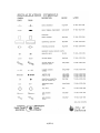
to by their acronym or abbreviation only. As a guide to the user, the following acronyms
or abbreviations which may appear shall have the meanings indicated herein:
AASHTO
American Association of the State Highway and Transportation
Officials
ACI
American Concrete Institute
ANSI
American National Standards Institute, Inc.
APWA
American Public Works Association
ASTM
American Society for Testing and Materials
AWWA
American Water Works Association
DNRP
King County Department of Natural Resources
DOE
Washington State Department of Ecology
DOH
Washington State Department of Health
FHWA
Federal Highway Administration
Health
Public Health -- Seattle and King County
NRCS
Natural Resource Conservation Service (formerly Soil
Conservation Service)
RCW
Revised Code of Washington
USEPA
United States Environmental Protection Agency
WAC
Washington Administrative Code
WDWF
Washington Department of Fish & Wildlife
WSDOT
Washington State Department of Transportation
Dl-04 GOVERNMENTAL AGENCY REQUIREMENTS
All construction on City, County or State roads or right-of-way shall be done in
accordance with that agency's standards and requirements and in accordance with all
franchise and/or permit requirements. The Contractor is responsible to determine these
requirements prior to construction.
Where conflict exists between these Standards and permit requirements, the most
stringent permit requirements shall take precedence.
D1-6
SURFACE WATER ENGINEERING STANDARDS
END OF CHAPTER D1
D1-7
JANUARY 2015
SURFACE WATER ENGINEERING STANDARDS
JANUARY 2015
CHAPTER D2 – THRESHOLDS AND PLAN SUBMITTAL
TABLE OF CONTENTS
D2-01
GENERAL ........................................................................................................ D2-1
D2-02
ADJUSTMENTS AND DEVIATIONS ........................................................... D2-1
D2-02.1
General .............................................................................................................. D2-1
D2-02.2
Adjustment and Deviation Criteria ................................................................... D2-1
D2-02.3
Adjustment and Deviation Process ................................................................... D2-2
D2-03
EXCEPTIONS ................................................................................................. D2-2
D2-04
ERRORS AND OMISSIONS .......................................................................... D2-2
D2-05
THRESHOLDS................................................................................................ D2-2
D2-05.1
Threshold Discharge Area ................................................................................ D2-2
D2-05.2
Applicability ..................................................................................................... D2-3
D2-05.3
Projects subject to Regulation ........................................................................... D2-3
D2-06
STORMWATER SITE PLANNING AND SUBMITTALS ........................... D2-7
D2-06.1
Submittal Requirements when site is vested in 2009 Storm Drainage Code .... D2-8
D2-06.2
Submittal Requirements for Minimum Requirements 1 through 5 only .......... D2-8
D2-06.3
Submittal Requirements for Minimum Requirements 1 through 9 (When MR6,
MR7, MR8 and/or MR9 apply in addition to MR1 through MR5) ................ D2-10
D2-07
PLAN FORMAT AND NOTES ..................................................................... D2-12
D2-07.1
Submittal Standards ........................................................................................ D2-12
D2-07.2
Storm Drainage General Plan Notes ............................................................... D2-15
D2-08
AS-BUILT DOCUMENTATION ................................................................. D2-19
D2-08.1
General Standards ........................................................................................... D2-19
D2-08.2
Required Information ...................................................................................... D2-20
D2 - 09
OPERATION AND MAINTENANCE MANUAL ....................................... D2-21
D2-09.1
Storm Drainage O&M Manual Agreement for Utilities Storm Connections (MR
1-5)…………………………………………………………………………..D2-21
D2-09.2
Storm Drainage O&M Manual Agreement for Utilities Extension Agreements
(MR 1-9)…………………………………………………………………….D2-22
SURFACE WATER ENGINEERING STANDARDS
JANUARY 2015
TABLES
Table 2.1 Treatment Requirements by Threshold Discharge Area.......................................... D2-6
Table 2.2 Flow Control & On-site Stormwater Management Requirements by Threshold
Discharge Area.......................................................................................................................... D2-7
FIGURES
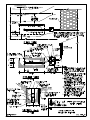
Figure 2.1 Threshold Discharge ............................................................................................... D2-3
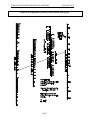
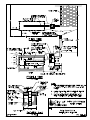
Figure 2.2 Flow Chart for Determining Requirements for New Development ....................... D2-4
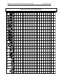
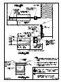
Figure 2.3 Flow Chart for Determining Requirements for Redevelopment ............................ D2-5
Figure 2.4 - Sample Stormwater Facility Maintenance Activity Log ..................................... D2-24
SURFACE WATER ENGINEERING STANDARDS
JANUARY 2015
CHAPTER D2 – THRESHOLDS AND PLAN SUBMITTAL
D2-01 GENERAL
Following these standards to design the stormwater system will help ensure a timely
review of the proposed project and keep review costs to a minimum.
A drainage system which includes unreasonable and intensive maintenance or operational
requirements as determined by the City shall be rejected in favor of a drainage system
which does not place undue burdens on the owner/operators of such system.
D2-02 ADJUSTMENTS AND DEVIATIONS
D2-02.1
General
The applicant may propose an Adjustment to the Minimum Requirements described in
BCC 24.06.065.D, or a Deviation from the Storm and Surface Water Engineering
Standards. Proposed Adjustments or Deviations must be project specific. An Adjustment
or Deviation may take longer to review, resulting in increased processing costs. The
Applicant acknowledges these risks when submitting a request for an Adjustment or
Deviation.
D2-02.2
Adjustment and Deviation Criteria
The City’s decisions to grant, deny, or modify proposed Adjustments or Deviations shall
be based on evidence that the request meets the following criteria:
1) Adjustment Criteria
A The Adjustment provides substantially equivalent environmental protection;
and
B The Adjustment is based on sound engineering practices; and
C The Adjustment meets the objectives of safety, function, environmental
protection and facility maintenance.
2) Deviation Criteria
A The Deviation will achieve the intended result through a comparable or
superior design; and
(a) The Deviation provides substantially equivalent environmental protection;
and
(b) The Deviation is based on sound engineering practices; and
D2-1
SURFACE WATER ENGINEERING STANDARDS
JANUARY 2015
(c) The Deviation meets the objectives of safety, function, environmental
protection, and facility maintenance.
D2-02.3
Adjustment and Deviation Process
Requests for Adjustments or Deviations shall be:
1) Provided to the Utilities Reviewer in writing prior to implementation; and
2) Demonstrate how the proposed Adjustment or Deviation meets criteria listed or
referenced above (e.g. written finding of fact); and
3) May be reviewed by the Utilities Technical Team before a decision is made; and
4) The decision by the City shall be final.
Any approved Adjustments or Deviations shall be included with the final approved
drainage plan.
D2-03
EXCEPTIONS
A request for an Exception to the Minimum Requirements may be submitted with a permit
or approval listed in LUC 20.35.015 (C) or, if none of the listed permits or approvals
apply to the project or if a decision is necessary to finalize the site layout, the applicant
may submit a request for an Exception with submittal of a Predevelopment Services
application. The Director may approve a request for an exception provided the applicant
can demonstrate compliance with the criteria contained in BCC 24.06.065(C).
D2-04
ERRORS AND OMISSIONS
Any errors or omissions in the approved plans or information used as a basis for such
approvals may constitute grounds for withdrawal of any approvals and/or stoppage of any
or all of the permitted work, as determined by the City. It shall be the responsibility of the
Developer to show cause why such work should continue, and make such changes in plans
that may be required by the City before the plans are approved.
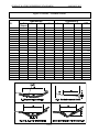
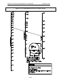
D2-05
THRESHOLDS
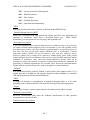
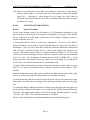
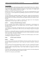
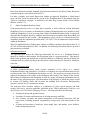
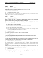
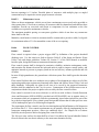
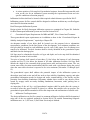
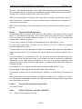
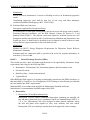
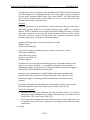
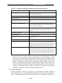
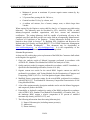
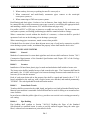
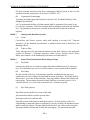
D2-05.1
Threshold Discharge Area
An onsite area draining to a single natural discharge location or multiple natural discharge
locations that combine within one-quarter mile downstream (as determined by the shortest
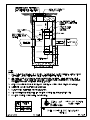
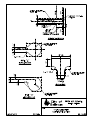
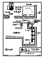
flow path) is a “threshold discharge area”. The examples in Figure 2.1 below illustrate this
definition. This definition is intended to clarify how the thresholds are applied to project
sites with multiple discharge points.
D2-2
SURFACE WATER ENGINEERING STANDARDS
JANUARY 2015
The City’s Land Use Code includes thresholds for pervious pavement for Land Use Code
purposes. Those thresholds may be different for Storm & Surface Water Utility Code
purposes. Use guidance herein for all Storm & Surface Water Utility Code purposes.
Figure 2.1 Threshold Discharge
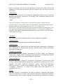
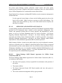
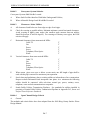
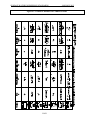
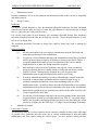
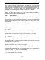
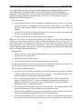
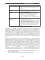
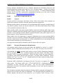
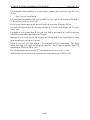
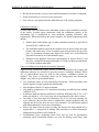
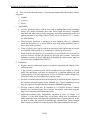
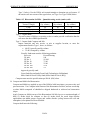
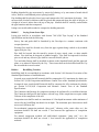
D2-05.2
Applicability
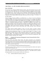
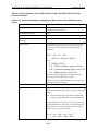
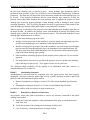
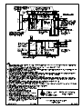
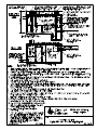
Thresholds help define the applicability of the Minimum Requirements to development
and redevelopment projects based on project type and size. A narrative description of the
threshold applicability process is included in Section 24.06.065 of the Storm and Surface
Water Utility Code. Figures 2.2 and 2.3 present the same applicability determination
process in flow chart graphics.
For redevelopment, if the runoff from the new impervious surfaces and converted pervious
surfaces is not separated from runoff from other surfaces on the project site, the
stormwater treatment facilities must be sized for the entire flow that is directed to them.
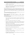
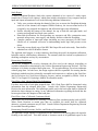
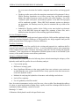
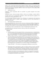
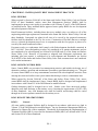
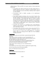
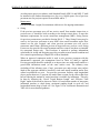
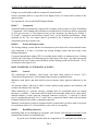
D2-05.3
Projects subject to Regulation
All project sites in Bellevue are subject to the Minimum Requirements per Chapter
24.06.065, unless exempt per 24.06.065(B), and are subject to the Minimum Requirements
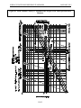
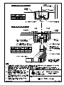
for development and redevelopment as outlined in Figure 2.2 and Figure 2.3.
D2-3
SURFACE WATER ENGINEERING STANDARDS
JANUARY 2015
Start Here
Does the site have
35% or more of
existing impervious
coverage?
See Figure 2.3 - Flow
Chart for Determining
Minimum Requirements
for Redevelopment
Yes
No
Does the project add
5,000 square feet or
more of new
impervious surfaces?
Does the project convert 3/4
acres or more of native
vegetation to lawn or
landscaped areas, or convert
2.5 acres or more of native
vegetation to pasture?
No
Yes
Yes
No
All Minimum
Requirements apply to
new impervious
surfaces and
converted pervious
surfaces.
Does the project have 2,000
square feet or more of new,
replaced, or new plus replaced
impervious surfaces?
Yes
Minimum Requirements
#1 through #5 apply to
the new and replaced
impervious surfaces and
the land disturbed.
Yes
No
Does the project have land disturbing activities of
7,000 square feet or more?
No
See the Minimum Requirement
#2, Construction Stormwater
Pollution Prevention
(BCC 23.76 - Clearing and
Grading Code)
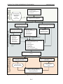
Figure 2.2 Flow Chart for Determining Requirements for New Development
D2-4
SURFACE WATER ENGINEERING STANDARDS
JANUARY 2015
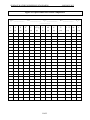
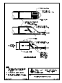
Do the new, replaced, or new plus replaced impervious surf aces total 2,000
square f eet or more?
OR
Does the land disturbing activity total 7,000 square f eet or more?
No
Yes
Minimum Requirements #1 through #5 apply
to the new and replaced impervious surf aces
and the land disturbed.
See the Minimum Requirement #2,
Construction Stormwater Pollution Prevention
(BCC 23.76 - Clearing and Grading Code)
Next Question
Does the project add 5,000 square f eet or more of new impervious surf aces?
OR
Convert 3/4 acres or more of native vegetation to lawn or landscaped areas?
OR
Convert 2.5 acres or more of vegetation to pasture?
Yes
No
Minimum Requirements #1 through #9 apply
to the new impervious surf aces and the
converted pervious surf aces.
Next
Question
Is this a road
related project?
Yes
No
Does the project add 5,000 square f eet or more of new impervious
No
Yes
Is the total of the new plus replaced
impervious surf aces 5,000 square f eet or
more, AND does the value of the proposed
improvements - including interior
improvements - exceed 50% of the assessed
value (or replacement value) of the existing
Do new impervious surf aces add 50% or
more to the existing impervious surf aces
within the project limits?
No
Yes
No additional
requirements.
No
Yes
No additional
requirements.
Minimum Requirements #1 through #9 apply
to the new and replaced impervious
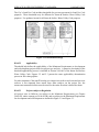
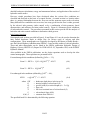
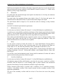
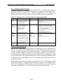
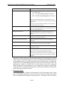
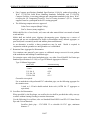
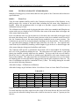
Figure 2.3 Flow Chart for Determining Requirements for Redevelopment
The Developer may meet the Minimum Requirements for an equivalent (flow and
pollution characteristics) area within the same site. This method is known as ‘Area
Substitution’. For public road projects, the water quality treatment for equivalent area
does not have to be within the project limits, but must drain to the same receiving water.
For flow control of public roads’ projects, the equivalent area must be in same stream
basin and capacity analysis must be done to demonstrate 100-year capacity is available. If
D2-5
SURFACE WATER ENGINEERING STANDARDS
JANUARY 2015
used for a project, the Developer must consult with the City to determine an appropriate
equivalent area.
Appendix C of Volume III of the DOE Manual directs users to model impervious area
directed to various low impact development facilities as landscaped area, 50% landscaped
area, or pasture. Those same modeling credits may be used when summing project areas to
determine whether the thresholds are exceeded.
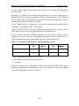
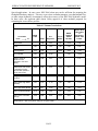
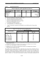
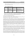
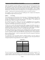
Project Thresholds for the construction of stormwater treatment facilities (MR6 Runoff
Treatment) are presented in Table 2.1 and include:
Projects in which the total of effective, pollution-generating impervious surface (PGIS) is
5,000 square feet or more in a threshold discharge area of the project, or
Projects in which the total of pollution-generating pervious surfaces (PGPS) is threequarters (3/4) of an acre or more in a threshold discharge area, and from which there is a
surface discharge in a natural or man-made conveyance system from the site.
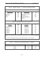
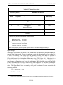
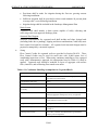
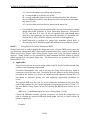
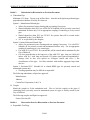
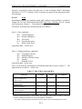
Table 2.1 Treatment Requirements by Threshold Discharge Area
< ¾ acres of
PGPS
> ¾ acres
PGPS
Treatment Facility
On-site Stormwater BMPs
< 5,000 sf
PGIS
> 5,000 sf
PGIS
PGPS = pollution-generating pervious surfaces
PGIS = pollution-generating impervious surfaces
sf = square ft
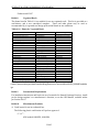
Project Thresholds for the construction of flow control facilities (MR7) and/or on-site
stormwater management (MR5) BMPs to achieve the standard flow control requirement
for western Washington are shown in Table 2.2.
D2-6
SURFACE WATER ENGINEERING STANDARDS
JANUARY 2015
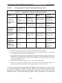
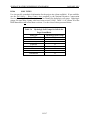
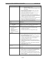
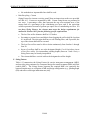
Table 2.2 Flow Control & On-site Stormwater Management Requirements by
Threshold Discharge Area
Flow Control
Facilities
< ¾ acres conversion to lawn/landscape,
or < 2.5 acres to pasture
> ¾ acres conversion to lawn/landscape,
or > 2.5 acres to pasture
On-site Stormwater
Management BMPs
< 10,000 square
impervious area
feet
of
effective
> 10,000 square
impervious area
feet
of
effective
> 0.1 cubic feet per second increase in
the 100-year flood frequency (1)
Note: (1) Estimated using the Western Washington Hydrology Model or other
approved model. See Chapter D3- Hydrology.
For MR5, On-site Stormwater Management, see Chapter D6.
For MR6, Runoff Treatment, see Chapter D5
For MR7, Flow Control, see Chapter D4
For Hydrologic Analysis information, see Chapter D3
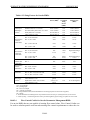
D2-06
STORMWATER SITE PLANNING AND SUBMITTALS
Based upon the analysis of existing site conditions, locate the buildings, roads, parking
lots, utilities, and landscaping features for the proposed development. Consider the
following points when laying out the site:
1) Fit development to the terrain to minimize land disturbance; Confine construction
activities to the least area necessary, and away from critical areas;
2) Preserve areas with natural vegetation (especially forested areas) as much as possible;
3) On sites with a mix of soil types, locate impervious areas over less permeable soil
(e.g., till), and try to restrict development over more porous soils (e.g., outwash);
4) Cluster buildings together;
5) Minimize impervious areas; and
6) Maintain and utilize the natural drainage patterns.
D2-7
SURFACE WATER ENGINEERING STANDARDS
JANUARY 2015
The development layout designed here will be used for determining threshold discharge
areas, for calculating whether thresholds for Minimum Requirements are exceeded, and
for the drawings and maps required for the Drainage Report and Stormwater Site Plan.
D2-06.1
Code
Submittal Requirements when site is vested in 2009 Storm Drainage
Projects are vested as described in the Clearing and Grading Code, BCC 23.76.045.
Generally, a complete application for building permit or subdivision sets vesting. Or, a
Clearing and Grading permit sets vesting if neither building nor subdivision processes are
applicable. Permit expiration results in loss of vesting.
Projects that are not required to submit a Utility Developer Extension Agreement:
Show the storm drainage connection on the site plan required with the permit application.
A Storm connection permit may also be required, as determined by the Utilities reviewer.
If using On-site Stormwater Management techniques, rather than a conventional tightline
connection, use D2-06.2 below.
Projects that are required to submit a Utility Developer Extension Agreement:
Show the storm drainage connection on the site plan required with the permit application.
A Utility Developer Extension Agreement must be submitted with, or prior to, the
Clearing and Grading and Building permits.
On-site Stormwater Management techniques may be used to reduce the size of flow
control and runoff treatment facilities. Select and design on-site facilities in accordance
with Chapter D6, and size facilities to satisfy the vested code requirements using an
approved model per Section D3-02 or the applicable standard.
D2-06.2
Submittal Requirements for Minimum Requirements 1 through 5 only
A Geotechnical Report as described in the Development Services plan description sheet
“Geotechnical Report and Stability Analysis Requirements,” is required when infiltration
facilities (including bioretention or pervious pavement) are proposed and there is a stream,
wetland, steep slope or landslide hazard area on or within 100 feet of the site.
Storm Drainage Report (no pages may be larger than 11” x 17”), including:
1) Project Overview
General description of project: pre-developed and developed site conditions site area;
square footage of each type of impervious surface, lawn and landscape areas, nondisturbance areas: and existing stormwater runoff conditions, including runoff from offsite, natural and manmade drainage systems.
Summary of proposed on-site stormwater management facilities. Use Chapter D6 in these
Standards to choose the facilities and explain why they were chosen.
D2-8
SURFACE WATER ENGINEERING STANDARDS
JANUARY 2015
2) Site Maps
A.
Existing Conditions
(a) Existing site and drainage conditions. Identify areas of high seasonal
groundwater per geotechnical report requirements.
(b) Show infiltration test locations. Note test method used, calculated longterm infiltration rates, and correction factors. Use the simplified
infiltration test per Section D4-06.7, or a method from Volume III,
3.3.6 of the DOE Manual.
3) Proposed Development
A Show each type of impervious surface, lawn and landscape areas, nondisturbance areas. Note the square footage of each, within each threshold
discharge area.
B Show the proposed on-site stormwater management facilities. Show setbacks,
as required by Land Use Code and Chapter D4.
GeoMapNW soils database, where available (primarily BelRed area). If not available,
Natural Resources Conservation Service (NRCS) Soil Survey Map for the location with
the site boundaries marked.
Drainage map, showing flow path from site to receiving water (up to ¼ mile), and
threshold discharge areas. Indicate the receiving water (lake or major stream). Include
upstream information for any areas draining onto the site. Include pipe sizes and
structures.
Sizing calculations, or simple sizing tables from Chapter D6, with applicable values
circled, for proposed on-site stormwater management facilities.
Permanent Stormwater Control Plan, including:
Show on-site stormwater management facilities on site plan, as required on
Development Services Submittal Requirements sheets for single family residential
or commercial sites.
Include sufficient profiles and details needed for review, for the Contractor to
construct the facilities, and for the constructed facilities to be verified by the City
inspector.
If a separate plan sheet is needed for clarity, use of the submittal standards in D206.2 is recommended.
D2-9
SURFACE WATER ENGINEERING STANDARDS
JANUARY 2015
If a Utility Developer Extension Agreement is required for water, sewer or storm
drainage facilities, Plans for the drainage facilities may be combined with water
and sewer if they remain readable.
As-Built drawings must be submitted following inspection, prior to occupancy, and
approved by the City.
Operation and Maintenance Manual (O & M Manual) for Stormwater Management
Facilities per Section D2-09.
D2-06.3
Submittal Requirements for Minimum Requirements 1 through 9
(When MR6, MR7, MR8 and/or MR9 apply in addition to MR1 through MR5)
Geotechnical Report and Stability Analysis Requirements, as described in Development
Services plan description sheet.
Storm Drainage Report (no pages may be larger than 11” x 17”), including:
1) Project Overview
General description of project: pre-developed and developed site conditions, site area;
square footage of each type of impervious surface, lawn and landscape areas, and nondisturbance areas; existing stormwater runoff conditions, including runoff from off-site,
natural and manmade drainage systems.
Summary of proposed on-site stormwater management facilities. Use Chapter D6 in these
Standards to choose the facilities and explain why they were chosen.
Vicinity map showing the property location, all roads bordering the site, significant
geographic features, and critical areas and their buffers, and flow path(s) from site to
receiving water (up to 1 mile). Include upstream information for any areas draining onto
the site. Include pipe sizes and structures.
2) Site Maps showing:
A Existing Conditions
(a) Existing site and drainage conditions. Identify areas of high seasonal
groundwater.
(b) Infiltration test locations, test method used, calculated long-term
infiltration rates, and correction factors.
B Proposed Development
(a) Show each type of impervious surface, lawn and landscape areas, and
non-disturbance areas. Note the square footage of each.
D2-10
SURFACE WATER ENGINEERING STANDARDS
JANUARY 2015
3) Show the proposed on-site stormwater management facilities. Show setbacks, as
required by Land Use Code and Chapter D4.
4) GeoMapNW soil map, or if not available, NRCS Soil Survey Map for the location
with the site boundaries marked.
5) Drainage map, showing flow path from site to receiving water (up to ¼ mile), and
threshold discharge areas.
Indicate the receiving water (lake or major stream).
Include upstream information for any areas draining onto the site. Include pipe sizes
and structures.
6) Sizing calculations, for proposed on-site stormwater management facilities. These
calculations shall bear the signature and stamp of the responsible Civil Engineer.
Include:
A Provide narrative, mathematical, and graphic presentations of model input
parameters selected for the developed site condition, including acreage, soil
types, and land covers, road layout, and all drainage facilities.
B Developed basin areas, threshold discharge areas, and flows should be shown
on a map and cross-referenced to computer printouts or calculation sheets.
Developed basin flows should be listed and tabulated.
C Any documents used to determine the developed site hydrology should be
included. Whenever possible, maintain the same basin name as used for the
pre-developed site hydrology. If the boundaries of a basin have been modified
by the project, that should be clearly shown on a map and the name modified to
indicate the change.
D If treatment facilities are proposed, provide a listing of the water quality menus
used per Section D5-03. If flow control facilities are proposed, provide a
confirmation of the flow control standard being achieved (e.g., the DOE flow
duration standard).
E A drawing of the flow control and treatment facilities and appurtenances. Show
basic measurements necessary to calculate the storage volumes available from
zero to the maximum head, all orifice/restrictor sizes and head relationships,
control structure/restrictor placement, and placement on the site.
F Include computer printouts, calculations, equations, references, storage/volume
tables, graphs as necessary to show results and methodology used to determine
the storage facility volumes. Runoff model documentation files should be
included. See D3-02 for a list of approved models.
D2-11
SURFACE WATER ENGINEERING STANDARDS
JANUARY 2015
G Present an analysis of existing downstream conveyance system capacity if
additional flow is being routed to that system.
H Present an analysis and design of the proposed stormwater conveyance system
for the project, using an approved model. All pipes, culverts, catch basins,
channels, swales, and other stormwater conveyance appurtenances must be
clearly labeled and correspond directly to the engineering plans.
7) Permanent Stormwater Control Plan
A Show on-site stormwater management facilities on the site plan, as required on
Development Services Submittal Requirements sheets for single family
residential or commercial sites.
B Include sufficient profiles and details needed for review, for the Contractor to
construct the facilities, and for the City inspector to verify them.
C If a Utility Developer Extension Agreement is required for water or sewer as
well as storm drainage facilities, plans for the drainage facilities may be
combined with water and sewer if they remain readable.
As-Built drawings must be submitted following inspection, prior to occupancy, and
approved by the City.
Operation and Maintenance Manual (O & M Manual) for Stormwater Management
Facilities per Section D2-09.
D2-07 PLAN FORMAT AND NOTES
D2-07.1
Submittal Standards
1)
Submittal Standards vary by size and type of project. Refer to handouts provided by
City of Bellevue Development Services for Submittal Requirements. Utility plans
submitted for review shall meet the City's "Boundary & Topographic Survey" and
"Site Plan B" requirements. Current copies of these requirements are available at the
Bellevue Development Services Center and the City’s website.
2)
Combining Plans - Water, sanitary sewer and storm drainage designs (complete plan
and profile) shall be on separate plan sheets, although alignments of all Utilities shall
be shown on each utility plan. Plan sets for all 3 Utilities can be combined for small
projects if information is readable. Designs for water and sewer can be combined on
the same plan sheets if plan scale is 1”=10’, V=20’, or 1’"=30’. Contact the Utility
representative in the Permit Center for approval to combine plans.
D2-12
SURFACE WATER ENGINEERING STANDARDS
JANUARY 2015
3)
Plan submittals shall conform to Development Services “Standards for Plans and
Drawings”, and also include:
4)
Title Block - Border and title block shall conform to standard City of Bellevue
format. See Appendix D-2.
5)
Project Name Utility Extension (UE) permit number if applicable, Section Township - Range, and Site Address shall be included in title block (lower right
hand corner).
6)
Engineering Plans - Plan, profile and detail sheet(s) for the proposed drainage
system.
a) Plan View
i) List pipe length, size and material alongside of pipe, e.g. 150 L.F. - 8" PVC.
Pipe material can be listed in a general note in lieu of listing along pipe.
ii) Pipe length is to be based on horizontal distance between center of manholes.
iii) Indicate direction of flow with arrows on end of pipe entering manhole.
b) Profile View
i) List pipe length, size, material and slope to 4 decimal places (ft per ft), e.g. 150
L.F. - 8" PVC S=0.0125. Pipe material can be listed in a plan note in lieu of
listing on profile.
ii) Slope is based on invert elevation OUT of upstream manhole, invert elevation
INTO downstream manhole and horizontal distance between center of
manholes.
7)
Site Areas - Total area, Existing and Proposed Pervious and Impervious areas, areas
within Native Growth Protection Easements (NGPE), etc. on the drainage plan
sheet(s).
8)
Hydrologic and Hydraulic Data - Design volumes and allowable release/ discharge
rates for flow control and runoff treatment facilities shall be tabulated on the plans.
Provide space for as-built volume and release rates.
9)
Scale - Be consistent and indicate your scale on each sheet using a bar symbol (for
Plan reproduction integrity). Drawings are to be in a scale of 1” = 10', 1” = 20’ or 1”
= 30’ for combined utility plans. Drawings at 1” = 40’ or 1” = 50’ scale shall show
utility plans on separate sheets. Architectural scales for utility drawings will not be
D2-13
SURFACE WATER ENGINEERING STANDARDS
JANUARY 2015
accepted. If the scale results in more than three pages of plan sheets, a cover sheet
showing the entire project site (at a smaller scale) shall be provided.
10) North Arrow - Include on all plan view drawings. North arrow shall face up and/or
to the right hand side of plan sheet.
11) Datum - Show both horizontal (NAD-83) (NSRS 2011) and vertical (NAVD 88)
control points. Specify the benchmark to be used for vertical control during
construction. For sites with FEMA-mapped floodplains, label the 100-year
floodplain elevation with the NGVD29 and NAVD88 values.
12) The survey of the site, for both design and as-builting, shall be accurately referenced
to the Washington State Plane Coordinate System (NAD-83) (NSRS 2011) by field
ties to at least two City of Bellevue survey control network monuments. All
elevations shall be referenced to the North American Vertical Datum of 1988
(NAVD 88). Information on the City of Bellevue survey control network is available
by contacting the Transportation Department, Property Services Division, at (425)
452-6019.
13) Vicinity Map - Include on the plan for each utility. The vicinity map covers the
project site and surrounding streets and property within a minimum of 600' of the
site. Copies of a city map can be made from the Street Atlas in the Self Help area of
the Permit Center.
14) Line types shall clearly distinguish existing utilities from new; new facilities should
be a heavier line type.
15) Drafting Media - Plans sheets shall be on 24" x 36" or 22" x 34" mylar, matte on
both sides.
16) Drafting Standards - Plotting shall be on mylar with a non-smudging, ink or ink-like
media. Pencil drawings (including corrections or alterations) shall not be accepted.
17) Drafting standards/symbols shall conform to Washington State APWA Chapter
CAD Standards. See Appendix D-3. Lettering shall be done with "Leroy-style" font
(SIMPLEX font if using AutoCAD).
18) Text identifying existing features shall be 0.08" in height (Leroy 80 template).
19) Text identifying street names shall be 0.24" in height (Leroy 240 template).
20) Text for instructions and call outs for proposed facilities shall be 0. 12" in height
(Leroy 120 template).
D2-14
SURFACE WATER ENGINEERING STANDARDS
JANUARY 2015
21) On plans with more than one sheet, stationing shall proceed from left to right or from
bottom to top.
22) Upon completion of construction, as-builts shall be provided in digital format for asbuilting and permanent record. The digital format shall be in AutoCAD Version
2004 through 2011 (no older or newer). The "DWG" file(s) on a CD ROM. The
AutoCAD' files shall include all plans, profiles, notes, and details of the surface
water improvements.
23) Making Copies of Plans - Blueline or blackline prints and photocopies are
acceptable. Brownline prints and microfilm copies of plans will not be accepted.
24) Type of Paper for Plan Copies - Blueprint quality or standard drafting paper. Tissue
paper, graph paper, poster board, cardboard, and similar materials will not be
accepted.
D2-07.2
Storm Drainage General Plan Notes
The following is a listing of General Notes that should be incorporated in the drainage
plan set. All the notes on the list may not pertain to every project. The Developer may
omit non-relevant notes as determined by the Utility. However, do not renumber the
remaining General Notes. If additional notes are needed for specific aspects, they should
be added after the General Notes.
Storm Drainage General Notes:
(1)
All work shall conform to the 2013 edition of the City of Bellevue Utilities
Department Engineering Standards and the Developer Extension Agreement.
(2)
Storm pipe shall be PVC conforming to ASTM D-3034 SDR 35 (4” – 15”) or ASTM
F-679 (18”-27”). Bedding and backfill shall be as shown in the Standard Details.
(3)
The locations of all existing utilities shown hereon have been established by field
survey or obtained from available records and should therefore be considered
approximate only and not necessarily complete. It is the sole responsibility of the
excavator to independently verify the accuracy of all utility locations shown, and to
further discover and avoid any other utilities not shown here on which may be
affected by the implementation of this plan. Immediately notify the Engineer if a
conflict exists.
(4)
The footing drainage system and the roof downspout system shall not be
interconnected and shall separately convey collected flows to the conveyance system
or to on-site stormwater facilities.
D2-15
SURFACE WATER ENGINEERING STANDARDS
JANUARY 2015
(5)
Provide and maintain temporary sedimentation collection facilities to ensure that
sediment or other hazardous materials do not enter the storm drainage system in
accordance with the sites approved CSWPPP. For all construction during the rainy
season, downhill basins and inlets must be protected with catch basin inserts. Simply
placing filter fabric under the grate is not acceptable.
(6)
Prior to final inspection and acceptance of storm drainage work, pipes and storm
drain structures shall be cleaned and flushed. Any obstructions to flow within the
storm drain system, (such as rubble, mortar and wedged debris), shall be removed at
the nearest structure. Wash water of any sort shall not be discharged to the storm
drain system or surface waters.
(7)
Ends of each storm drain stub at the property line shall be capped and located with
an 8' long 2" x 4" board, embedded to the stub cap and extending at least 3 feet
above grade, and marked permanently "STORM". A copper 12 ga. locate wire
firmly attached. The stub depth shall be indicated on the marker.
(8)
All grates in roadways shall be ductile iron, bolt-locking, vaned grates per the
Standard Details. Structures in traffic lanes outside of the curbline which do not
collect runoff shall be fitted with round, bolt-locking solid covers. Off-street
structures which do not collect runoff shall be fitted with bolt-locking solid covers.
(9)
Vegetation/landscaping in the detention pond, bioretention facility, vegetated roof
and/or drainage swale(s) are an integral part of the runoff treatment system for the
project. Such drainage facilities will not be accepted until plantings are established.
(10) All new manholes shall have a minimum inside diameter of 48” and shall conform to
the Standard Details. All new catch basins shall conform to the Standard Details.
(11) Side storm stations are referenced from nearest downstream manhole/ catch basin.
(12) All testing and connections to existing mains shall be done in the presence of a
representative of the City of Bellevue Utilities Department.
(13) All trenches shall be compacted, and Hot Mix Asphalt in place in paved areas, prior
to testing storm lines for acceptance.
(14) All public storm drains shall be air tested and have a video inspection performed
prior to acceptance (see #23 below). Storm main constructed with flexible pipe shall
be deflection tested with a mandrel prior to acceptance.
(15) Storm stubs shall be tested for acceptance at the same time the main storm is tested.
(16) All manholes/ catch basins in unpaved areas shall include a concrete seal around
adjustment rings per Standard Details.
D2-16
SURFACE WATER ENGINEERING STANDARDS
JANUARY 2015
(17) All storm main extensions within the public right-of-way or in easements must be
“staked” by a surveyor licensed in Washington State for “line and grade” and cut
sheets provided to the Engineer, prior to starting construction.
(18) The Contractor shall use a vacuum street sweeper to remove dust and debris from
pavement areas as directed by the Engineer. Flushing of streets shall not be
permitted without prior City approval.
(19) Storm drainage mainlines, stubs and fittings shall be constructed using the same pipe
material and manufacturer. Connections between stubs and the mainline will be
made with a tee fitting. Tee fitting shall be from same manufacturer as pipe. Cut-in
connections are only allowed when connecting a new stub to an existing mainline.
(20) Manholes, catch basins and vaults are considered to be permit-required confined
spaces. Entry into these spaces shall be in accordance with Chapter 296-809 WAC.
(21) Placement of surface appurtenances (MH lids, valve lids, etc.) in tire tracks of traffic
lanes shall be avoided whenever possible.
(22) Call 1-800-424-5555, or 8-1-1, 72 hours before construction for utility locates.
(23) The Contractor shall perform a video inspection and provide a DVD of the storm
pipe interior for the City’s review. The video shall provide a minimum of 14 lines
per millimeter resolution and cover the entire length of the applicable pipe. The
camera shall be moved through the pipe at a uniform rate (≤ 30 ft/min), stopping
when necessary to ensure proper documentation of the pipe condition. The video
shall be taken after installation and cleaning to insure that no defects exist. The
project will not be accepted until all defects have been repaired.
(24) Clearly label public and private systems on the plans. Private systems shall be
marked “private” and shall be maintained by the property owner(s).
(25) All concrete structures (vaults, catch basins, manholes, oil/water separators, etc.)
shall be vacuum tested.
(26) Manholes, catch basins and inlets in easements shall be constructed to provide a
stable, level grade for a minimum radius of 2.5 feet around the center of the access
opening to accommodate confined space entry equipment.
(27) Tops of manholes/ catch basins within public right-of-way shall not be adjusted to
final grade until after paving.
(28) Contractor shall adjust all manhole/ catch basin rims to flush with final finished
grades, unless otherwise shown.
D2-17
SURFACE WATER ENGINEERING STANDARDS
JANUARY 2015
(29) Contractor shall install, at all connections to existing downstream manholes/catch
basins, screens or plugs to prevent foreign materials from entering existing storm
drainage system. Screens or plugs shall remain in place throughout the duration of
the construction and shall be removed along with collected debris at the time of final
inspection and in the presence of a representative of the City of Bellevue Utilities
Department.
(30) Surface restoration of existing asphalt pavement shall be as required by the right-ofway use permit.
(31) The Contractor shall maintain a minimum of five feet (5’) horizontal separation
between all water and storm drainage lines. Any conflict shall be reported to the
Utility and the Developer’s Engineer prior to construction.
(32) It shall be the Contractor’s responsibility to ensure that no conflicts exist between
storm drainage lines and proposed or existing utilities prior to construction.
(33) Before commencement of trenching, the Contractor shall provide filter fabric for all
downhill storm drain inlets and catch basins, which will receive runoff from the
project site. The contractor shall periodically inspect the condition of all filter fabric
and replace as necessary.
(34) Minimum cover over storm drainage pipe shall be 2 feet, unless otherwise shown.
(35) Avoid crossing water or sewer mains at highly acute angles. The smallest angle
measure between utilities should be 45 degrees.
(36) At points where existing thrust blocking is found, minimum clearance between
concrete blocking and other buried utilities or structures shall be 5 feet.
(37) When work is to occur in easements, the Contractor shall notify the easement grantor
and Bellevue Utilities in writing a minimum of 48 hours in advance of beginning
work (not including weekends or holidays). Failure to notify grantor and Bellevue
Utilities will result in a Stop Work Order being posted until the matter is resolved to
the satisfaction of Bellevue Utilities. A written release from the easement grantor
shall be furnished to the Utilities Inspector prior to permit sign-off.
(38) The Contractor shall restore the Right-of-Way and existing public storm drainage
easement(s) after construction to a condition equal or better than condition prior to
entry. The Contractor shall furnish a signed release from all affected property
owners after restoration has been completed.
D2-18
SURFACE WATER ENGINEERING STANDARDS
JANUARY 2015
(39) Where a new utility line crosses below an existing AC main, the AC pipe shall be
replaced with DI pipe to 3 feet past each side of the trench as shown on Standard
Detail W-8. Alternatively, where directed by the Utility, the trench shall be
backfilled with controlled density fill (CDF, aka flowable fill) from bottom of trench
to bottom of AC main.
D2-08
AS-BUILT DOCUMENTATION
D2-08.1
General Standards
For all storm drainage projects, the Developer or City Department responsible for the
project shall provide surveyed as-built plans at completion of the project. This includes
private commercial or multi-family systems that the Developer’s Engineer provides a
written compliance letter for.
As-built plans shall be based on field survey information. All survey work shall be
performed under the supervision of a Professional Land Surveyor registered in the State of
Washington. The surveyed as-built shall contain the following information submitted in
both electronic (AutoCAD) format and on a mylar plan stamped and signed by the
surveyor. Horizontal locations shall be recorded to within one tenth (0.1’) of a foot. Rim
and invert elevations at drainage structures shall be recorded to within one one-hundredth
(0.01’) of a foot. Use Washington Coordinate System NAD 83 (NSRS 2011) – North
Zone as the basis of bearings for all surveys. Prepare survey according to City of Bellevue
NAVD 1988 vertical datum and state that it was the datum used.
All pipe lengths and dimensions are based on horizontal distances, unless slope is greater
than 10%, to measure horizontal distance, inspector should note that length is “slope
distance”.
References/dimensions from right-of-way centerline for utility features in the public rightof-way, or from property line for utility features located within easements.
As-built information shall be recorded on plan and profile views of the contract drawings.
The profile view shall note any changes from the design finished grade over each pipe
line.
As-built plans shall be submitted to Bellevue Utilities using the approved mylar plan set as
the basis for the redlined as-built plans. An as-built plan set in digital format shall also be
submitted. The digital format shall be in AutoCAD Version 2004 through 2011 (no older
or newer). The “DWG” file(s) shall be submitted on CD ROM.
The Developer will perform as-built documentation for Storm Drainage projects.
D2-19
SURFACE WATER ENGINEERING STANDARDS
D2-08.2
JANUARY 2015
Required Information
Mains:
Length (center of manhole/catch basin to center of manhole/catch basin), diameter,
material, slope, direction of flow, note “private” if applicable, for privately maintained
facilities. Show private systems going to apartments, condominiums, commercial sites,
and joint-use side storm drains. Label private system components as “PRIVATE
SYSTEM”. Other than joint-use systems, do not show single family private systems,
other than stub from public main.
Ditches:
Length, direction of flow, material and slope of all constructed open channels, note
“private” if applicable.
Stubs:
Lengths, depth, station (stationing of stubs referenced from downstream structure),
distance from property line. List slope if different than standard 2% and size if different
than standard 6”.
Existing Structures:
Where new pipes connect to existing structures, the Utilities ID number of the existing
structure shall be noted on the drawing. ID numbers can be obtained from the Storm
Drainage Maps.
Ponds, Bioswales, and Bioretention Facilities:
Locations, topographic features and dimensions of all flow control and runoff
treatment ponds, bioswales and bioretention facilities. Include bottom and top
elevations, and in plan view included labeled contour lines at one-foot 1intervals.
As-built revisions to any detail drawings that provide information associated with
ponds and bioswales, such as cross-sections, pond or bioswale lining material
specifications (e.g. grass, plantings, etc.), plan or profile views, spillway elevation,
etc.
Location, type, size and elevation at tops, inverts and bottoms of any drainage
system facilities adjacent to each pond, such as control structures, catch basins, etc.
Dimensions from Right-of-Way centerline or property line.
Notes and details about unusual situations and features.
Plant details including the type of plant.
D2-20
SURFACE WATER ENGINEERING STANDARDS
JANUARY 2015
For private storm drainage systems (collection, runoff control, and water quality
treatment), the Developer’s Engineer shall submit a compliance letter, on a form furnished
by the Utilities Department, for constructed the storm drain facilities.
Single Family Private Systems, including MR5 facilities (on-site stormwater management)
on individual lots:
Use the approved storm design as shown on the building permit site plan as the
basis for the as-built. Make revisions as necessary to reflect field changes. The
changes need not be drafted (e.g. they can be edits marked on the site plan), but
they must be readable.
D2 - 09
OPERATION AND MAINTENANCE MANUAL
A storm drainage operation and maintenance manual (O & M Manual) agreement shall be
provided for all constructed source controls, on-site stormwater management, flow
control, and treatment facilities that are owned, operated, and maintained by private
parties, as well as City Parks Department and Civic Services Facilities. For projects
triggering Minimum Requirements 1 through 5, the Storm Drainage O&M Manual
Agreement for Utilities Storm Connections (MR 1-5) shall be provided. For projects
triggering Minimum Requirements 1 through 9, the Storm Drainage O&M Manual
Agreement for Utility Extension Agreements (MR1-9) shall be provided.
Public drainage facilities, located in the public right-of-way and in dedicated easements,
which are accepted by the City of Bellevue Storm and Surface Water Utility are operated
and maintained as per the current edition of the City of Bellevue Storm and Surface Water
Maintenance Standards, now or as hereafter amended. Individual O&M Manuals are not
provided for these public drainage facilities. City Parks Department and Civic Services
are required to provide an O&M Manual agreement.
D2-09.1
Storm Drainage O&M Manual Agreement for Utilities Storm
Connections (MR 1-5)
The Storm Drainage O&M Manual Agreement for Utilities Storm Connections (MR 1-5),
at a minimum, shall include:
The name of the property owner(s) responsible for maintenance and operation of
the system.
The property address.
The Storm Connection Permit (UB Permit) number and issue date project is
permitted under.
The on-site stormwater management facility types permitted.
D2-21
SURFACE WATER ENGINEERING STANDARDS
JANUARY 2015
Site diagram of the constructed (As-Built) storm drainage system, identifying the
components, with profiles as needed.
Agreement to maintain facilities in accordance with City of Bellevue Storm and
Surface Water Code (24.06.065) and the Storm and Surface Water Maintenance
Standards, now or as hereafter amended.
The final O&M Manual for MR 1-5 must be submitted and approved by the Utilities
Department prior to the Storm Connection Permit acceptance, where applicable, or prior
to occupancy. The O & M Manual for MR 1-5 must conform to King County’s recording
format requirements and be recorded against the property, as a covenant running with the
land.
A copy of the manual shall be retained onsite or within reasonable access to the site, and
shall be transferred with the property to the new owner.
D2-09.2 Storm Drainage O&M Manual Agreement for Utilities Extension
Agreements (MR 1-9)
The Storm Drainage O&M Manual Agreement for Utilities Extension Agreements (MR 19), at a minimum, shall include:
The name of the party (or parties) responsible for maintenance and operation of the
system, such as a Home Owners association, management company or the legal
property owner.
Property legal description, address and project name, if applicable.
Agreement to maintain facilities in accordance with City of Bellevue Storm and
Surface Water Code (24.06.065) and the Storm and Surface Water Maintenance
Standards, now or as hereafter amended.
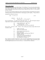
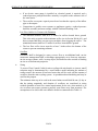
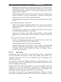
A log of maintenance activities that indicates what actions have been taken, when
and by whom. Log shall be kept available for inspection by City of Bellevue at
any time. See Figure 2.4 below for recommended activity log format.
Prominently note the manual and log sheets location on site.
Maintenance instructions for any components not covered by the maintenance
standards referenced above.
An engineer’s statement describing the storm drainage facilities and overall
system, and how it is intended to function.
Site diagram of the constructed (As-Built) storm drainage system, identifying the
components, with profiles as needed.
D2-22
SURFACE WATER ENGINEERING STANDARDS
JANUARY 2015
As-Built details of components, particularly flow control and treatment facilities,
as needed for maintenance.
A draft must be submitted to the Utilities Department during the plan review process. The
final O&M Manual for MR 1-9 must be approved by the Utilities prior to Utility
Extension acceptance, where applicable, or prior to occupancy. The O & M Manual for
MR 1-9 must conform to King County’s recording format requirements and be recorded
against the property, as a covenant running with the land.
A copy of the manual shall be retained onsite or within reasonable access to the site, and
shall be transferred with the property to the new owner. The manual and log sheets must
be available for inspection by the City of Bellevue upon request.
The O&M Manual for MR 1-9 shall be adjusted or revised at the end of the one (1) year
warranty period, if needed, as a result of inspection findings and recommendations by the
City. The revised O & M Manual shall be recorded against the property.
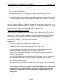
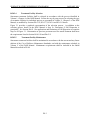
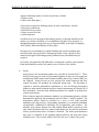
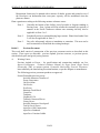
List regularly scheduled maintenance on a separate checklist based on the facility’s O&M
Manual for MR 1-9, and keep the checklist with this maintenance activity log.
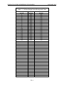
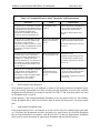
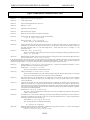
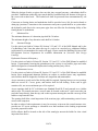
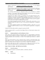
A sample “Maintenance Activity Log” is shown in Figure 2.4.
D2-23
SURFACE WATER ENGINEERING STANDARDS
JANUARY 2015
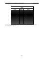
Figure 2.4 - Sample Stormwater Facility Maintenance Activity Log for NPDES
Permit
To be completed and provided to the City of Bellevue annually.
Send copy by fax to: 425-452-7116, or by mail to: Bellevue Utilities, Water Quality, P.O.
Box 90012, Bellevue, WA 98009.
Property Name/Owner:
Site Address:
Property Manager/Contact:
Phone:
Storm Drainage Facility Type(s):
Location(s) on Property: (indicate on site map if
possible)
Date
Reason
for
Inspection/Action (circle
one)
Condition Observed
Complaint or Problem
Regular Maintenance
Complaint or Problem
Regular Maintenance
Complaint or Problem
Regular Maintenance
Complaint or Problem
Regular Maintenance
Complaint or Problem
Regular Maintenance
Complaint or Problem
Regular Maintenance
Complaint or Problem
Regular Maintenance
D2-24
Action Taken
Initials
SURFACE WATER ENGINEERING STANDARDS
END OF CHAPTER D2
D2-25
JANUARY 2015
SURFACE WATER ENGINEERING STANDARDS
JANUARY 2015
CHAPTER D3 - HYDROLOGIC ANALYSIS
TABLE OF CONTENTS
D3-01
GENERAL ................................................................................................................ D3-1
D3-02
HYDROLOGIC MODELS ....................................................................................... D3-1
D3-02.01
Ecology Approved Continuous Simulation Hydrology Model ....................... D3-2
D3-02.02
Single Event Hydrograph Method................................................................... D3-3
D3-02.03
Rational Method ............................................................................................ D3-11
D3-03
SUMMARY OF DESIGN FLOW .......................................................................... D3-14
D3-04
MINIMUM IMPERVIOUS AREAS ...................................................................... D3-15
D3-05
FLOW CONTROL EXEMPTIONS ....................................................................... D3-16
D3-06
SOIL TYPES ........................................................................................................... D3-17
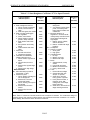
LIST OF TABLES
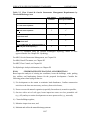
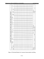
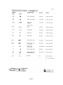
Table 3.1 Acceptable Uses of Runoff Computation Methods ................................................ D3-2
Table 3.2
24 Hour Design Storm Hyetograph Values ........................................................... D3-4
Table 3.3
Runoff Coefficients - "C" Values For The Rational Method .............................. D3-12
Table 3.4
Coefficients For The Rational Method “Ir" - Equation ....................................... D3-12
Table 3.5
kR Values For Tt Using The Rational Method .................................................... D3-14
Table 3.6
Hydrologic Soil Groups for Soils in the Puget Sound Basin .............................. D3-17
LIST OF FIGURES
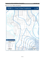
Figure 3.1 2-Year 24-Hour Precipitation ................................................................................ D3-8
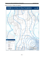
Figure 3.2 10-Year 24-Hour Precipitation .............................................................................. D3-9
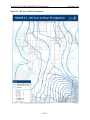
Figure 3.3 100-Year 24-Hour Precipitation ......................................................................... D3-10
SURFACE WATER ENGINEERING STANDARDS
JANUARY 2015
CHAPTER D3 - HYDROLOGIC ANALYSIS
D3-01
GENERAL
Hydrologic analysis is used to size conveyance, determine flow control levels and size water
quality treatment facilities. This chapter describes the models and methods of analyses required
or allowed by the City.
D3-02
HYDROLOGIC MODELS
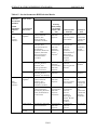
Various hydrologic models and methods assist in the planning and design of stormwater
conveyance, flow control and water quality treatment. Table 3.1 below lists the models and
methods approved for use.
D3-1
SURFACE WATER ENGINEERING STANDARDS
D3-02.01
JANUARY 2015
Ecology Approved Continuous Simulation Hydrology Model
Table 3.1 Acceptable Uses of Runoff Computation Methods
TYPE OF
COMPUTATION
PEAK FLOW
CONVEYANCE
SIZING (DESIGN
FLOWS)
FLOW CONTROL
(NEW/EXISTING) &
WQ FACILITY
SIZING AND
ANALYSIS
Allowed For
Rational Method
Single Hydrograph
Method
Tributary Areas
<
10 ac
(measured to
individual conveyance
elements)
REQUIRED for undetained areas,(1)
OKAY for detained
areas if no storage
routing is performed
OKAY if no storage
routing is performed.
Tributary Areas
10 ac
OKAY if no storage
routing is performed
OKAY if no storage
routing is performed
>=
Projects requiring
Water Quality
(MR
#6) and Flow Control
(MR #7)
Ecology Approved
Continuous
Simulation Model
OKAY if majority of
tributary area is
detained(2) and 15minute time steps (3)
are used.
OKAY if using 15minute time steps (3)
(storage routing is
allowed)
OKAY (must use 1hour time steps)
OKAY if no storage
routing is needed. 100yr rainfall.
OKAY for tributary
areas >= 10 acre if no
storage routing is
needed. 100-year, 24
hr.
OKAY if using 15minute time steps (3)
DOWNSTREAM
ANALYSIS
All Projects
PEAK FLOWS FOR
APPLYING
EXEMPTIONS &
THRESHOLDS
All Projects
OKAY (must use 1hour time steps)
All Projects
Apply Default(4) LID
Credits or derive LID
Credits with
demonstrative(5)
modeling
ON SITE
STORMWATER
MANAGEMENT
Notes:
(1) Undetained areas are those upstream of flow control facilities or other storage features.
(2) The majority of the tributary area is considered detained if the runoff from more than 50% of the tributary
area is detained by a flow control or other storage facility.
(3) The 15-minute time step references a computational time step best used with a rainfall time series that is
dissagregated to a comparable time step. King County maintains a 15-minute rainfall data base that was
created by disaggregating the historical hourly record. MGSFlood has developed a long-term, 5-minute
dissagregated rainfall time series.
(4) Default LID credits available in Appenidx III-C of Volume 3 of the DOE Manual.
(5) Requires use of proprietary modeling software that includes approved LID modeling approaches or
applicaion of HSPF incorporating modeling techniquesappropriate for characterizing LID
The Western Washington Hydrologic Model (WWHM) has been developed to aid in the design
of stormwater mitigation as required by Ecology. There are other HSPF derivatives that Ecology
has approved, including the King County Runoff Time Series model (KCRTS) and the
MGSFlood model. All incorporate HSPF algorithims or HSPF generated time series and should
D3-2
SURFACE WATER ENGINEERING STANDARDS
JANUARY 2015
produce comparable results provided they are using the same HSPF parameters and are using
similar rainfall records. The City of Bellevue accepts Ecology approved models.
Some HSPF- based models incorporate rainfall time series that have been dissaggregated to a
smaller time step that is more appropriate to use in sizing conveyance. Included are the KCRTS
model and version 4 of the MGSFlood model. The City will not accept 15 minute rainfall that
has not been disaggregated.
D3-02.02
Single Event Hydrograph Method
The Single Event Hydrograph Method (SBUH, NRSC or TR-55) is presented in Volume III
Chapter 2 of the DOE Manual. The design storm for all hydrograph analyses is a 24-hour
duration, standard SCS Type I A rainfall distribution resolved to 10-minute time intervals (Table
3.2 herein). See Figures 3.1 through 3.3 herein for the Bellevue 24-hour precipitation isopluvials.
D3-3
SURFACE WATER ENGINEERING STANDARDS
Table 3.2
JANUARY 2015
24 Hour Design Storm Hyetograph Values
Time from Beginning
of Storm
0
10
20
30
40
50
60
70
80
90
100
110
120
130
140
150
160
170
180
190
200
210
220
230
240
250
260
270
280
290
300
310
320
330
340
350
360
370
380
390
400
410
420
430
Percent
Rainfall
0.00
0.40
0.40
0.40
0.40
0.40
0.40
0.40
0.40
0.40
0.40
0.50
0.50
0.50
0.50
0.50
0.50
0.60
0.60
0.60
0.60
0.60
0.60
0.70
0.70
0.70
0.70
0.70
0.70
0.82
0.82
0.82
0.82
0.82
0.82
0.95
0.95
0.95
0.95
0.95
0.95
1.34
1.34
1.34
D3-4
Cumulative Percent
Rainfall
0.00
0.40
0.80
1.20
1.60
2.00
2.40
2.80
3.20
3.60
4.00
4.50
5.00
5.50
6.00
6.50
7.00
7.60
8.20
8.80
9.40
10.00
10.60
11.30
12.00
12.70
13.40
14.10
14.80
15.62
16.44
17.26
18.08
18.90
19.72
20.67
21.62
22.57
23.52
24.47
25.42
26.76
28.10
29.44
SURFACE WATER ENGINEERING STANDARDS
TABLE 3.2
JANUARY 2015
24 Hour Design Storm Hyetograph Values
(Cont.)
Time from Beginning
of Storm
440
450
460
470
480
490
500
510
520
530
540
550
560
570
580
590
600
610
620
630
640
650
660
670
680
690
700
710
720
730
740
750
760
770
780
790
800
810
820
830
840
850
860
870
Percent
Rainfall
1.80
1.80
3.40
5.40
2.70
1.80
1.34
1.34
1.34
0.88
0.88
0.88
0.88
0.88
0.88
0.88
0.88
0.88
0.88
0.88
0.88
0.72
0.72
0.72
0.72
0.72
0.72
0.72
0.72
0.72
0.72
0.72
0.72
0.57
0.57
0.57
0.57
0.57
0.57
0.57
0.57
0.57
0.57
0.57
D3-5
Cumulative Percent
Rainfall
31.24
33.04
36.44
41.84
44.54
46.34
47.68
49.02
50.36
51.24
52.12
53.00
53.88
54.76
55.64
56.52
57.40
58.28
59.16
60.04
60.92
61.64
62.36
63.08
63.80
64.52
65.24
65.96
66.68
67.40
68.12
68.84
69.56
70.13
70.70
71.27
71.84
72.41
72.98
73.55
74.12
74.69
75.26
75.83
SURFACE WATER ENGINEERING STANDARDS
TABLE 3.2
JANUARY 2015
24 Hour Design Storm Hyetograph Values
(Cont.)
Time from Beginning
of Storm
880
890
900
910
920
930
940
950
960
970
980
990
1000
1010
1020
1030
1040
1050
1060
1070
1080
1090
1100
1110
1120
1130
1140
1150
1160
1170
1180
1190
1200
1210
1220
1230
1240
1250
1260
1270
1280
1290
1300
Percent
Rainfall
0.57
0.50
0.50
0.50
0.50
0.50
0.50
0.50
0.50
0.50
0.50
0.50
0.50
0.40
0.40
0.40
0.40
0.40
0.40
0.40
0.40
0.40
0.40
0.40
0.40
0.40
0.40
0.40
0.40
0.40
0.40
0.40
0.40
0.40
0.40
0.40
0.40
0.40
0.40
0.40
0.40
0.40
0.40
D3-6
Cumulative Percent
Rainfall
76.40
76.90
77.40
77.90
78.40
78.90
79.40
79.90
80.40
80.90
81.40
81.90
82.40
82.80
83.20
83.60
84.00
84.40
84.80
85.20
85.60
86.00
86.40
86.80
87.20
87.60
88.00
88.40
88.80
89.20
89.60
90.00
90.40
90.80
91.20
91.60
92.00
92.40
92.80
93.20
93.60
94.00
94.40
SURFACE WATER ENGINEERING STANDARDS
TABLE 3.2
JANUARY 2015
24 Hour Design Storm Hyetograph Values
(Cont.)
Time from Beginning
of Storm
1310
1320
1330
1340
1350
1360
1370
1380
1390
1400
1410
1420
1430
1440
Percent
Rainfall
0.40
0.40
0.40
0.40
0.40
0.40
0.40
0.40
0.40
0.40
0.40
0.40
0.40
0.40
Cumulative Percent
Rainfall
94.80
95.20
95.60
96.00
96.40
96.80
97.20
97.60
98.00
98.40
98.80
99.20
99.60
100.00
*Table III-1.1 24-hour Design Storm Hyetograph Values from Stormwater Management Manual for the Puget
Sound, Department of Ecology, 1992
D3-7
SURFACE WATER ENGINEERING STANDARDS
Figure 3.1 2-Year 24-Hour Precipitation
D3-8
JANUARY 2015
SURFACE WATER ENGINEERING STANDARDS
Figure 3.2 10-Year 24-Hour Precipitation
D3-9
JANUARY 2015
SURFACE WATER ENGINEERING STANDARDS
Figure 3.3 100-Year 24-Hour Precipitation
D3-10
JANUARY 2015
SURFACE WATER ENGINEERING STANDARDS
D3-02.03
1)
JANUARY 2015
Rational Method
General
The Rational Method may be used with some specific limitations:
2)
Only for use in predicting a conservative peak flow rate to determine there
required capacity for conveyance facilities.
Drainage sub-basin area (A) shall not exceed 25 acres for a single calculation.
The time of concentration (Tc) must be computed using the method described below
and shall not exceed 100 minutes. It shall be made equal to 6.3 minutes when
computed to be less than 6.3 minutes.
Equation
The following is the traditional Rational Method equation:
QR = C*IR*A
QR
C
3)
= peak flow (cfs) for a storm of peak rainfall intensity "IR" of a given
return frequency (R)
= estimated
runoff coefficient (ratio of rainfall that becomes runoff)
IR
= peak rainfall intensity (inches/hour) for a given return frequency (R)
A
=
drainage sub-basin area (acres)
"C" Values
The allowable runoff coefficients to be used in this method are shown in Table 3.3 by type of
land cover. These values were selected following a review of the values previously acceptable
for use in the Rational Method in Bellevue and as described in several engineering handbooks.
The values for single family residential areas were computed as composite values (as illustrated
below) based on the estimated percentage of coverage by roads, roof, yards and unimproved
areas for each density. For drainage basins containing several land cover types, the following
formula may be used to compute a composite runoff coefficient "CC".
CC
= ((C1 x A1) + (C2 x A2) + …+ (Cn x An)) /At
where:
At
=
total area (acres)
A1,2,n
=
areas of land cover types
C 1,2,n
=
runoff coefficients for each area land cover type
D3-11
SURFACE WATER ENGINEERING STANDARDS
Table 3.3
JANUARY 2015
Runoff Coefficients - "C" Values For The Rational Method
GENERAL LAND COVERS
LAND COVER
C
Dense forest
Light forest
Pasture
Lawns
0.10
0.15
0.20
0.25
LAND COVER
Playgrounds (non-paved)
Gravel areas
Pavement and roofs
Open water (pond, lakes,
wetlands)
C
0.30
0.80
0.90
1.00
SINGLE FAMILY RESIDENTIAL AREAS
(Density is in dwelling units per gross acreage (DU/GA))
LAND COVER
DENSITY
0.20 DU/GA (1 per 5 ac.)
0.40 DU/GA
0.80 DU/GA
1.00 DU/GA
1.50 DU/GA
2.00 DU/GA
2.50 DU/GA
C
LAND COVER
DENSITY
C
0.17
0.20
0.27
0.30
0.33
0.36
0.39
3.00 DU/GA
3.50 DU/GA
4.00 DU/GA
4.50 DU/GA
5.00 DU/GA
5.50 DU/GA
6.00 DU/GA
0.42
0.45
0.48
0.51
0.54
0.57
0.60
For land covers not listed above, an area-weighted "C x At" sum should be computed based on the following
equation: C x At, = (Cl x A1,)+ (C2x A2) +…+ (Cn. X An), where At, = (Aa, + As + …= An), the total drainage basin
area.
* (For use only in determining peak design flow for analyzing and sizing pipes, culverts or channels)
Table 3.4
Coefficients For The Rational Method “Ir" - Equation
DESIGN STORM RETURN FREQUENCY (YEARS)
aR
bR
2 year
10 year
100 year
1.58
2.44
2.61
0.58
0.64
0.63
D3-12
SURFACE WATER ENGINEERING STANDARDS
4)
JANUARY 2015
“IR" Peak Rainfall Intensity
The peak rainfall intensity(IR )for the specified return frequency (R) design storm is determined
using a unit peak rainfall intensity factor (iR) for a given return frequency (R) design storm using
the following equation: IR = (Pr) (iR)
where:
Pr
=
is the total precipitation at the project site for the 24-hour duration
design storm event for the given return frequency (from the
Isopluvial Maps in Figures 3.1 through 3.3.
iR
=
(aR)(TC) –(bR); the unit peak rainfall intensity factor
TC
=
time of concentration (minutes), calculated using the method described below
only (Tc minimum value is 6.3 minutes).
aR and bR are coefficients (from Table 3.4) used to adjust the equations for the design storm
return frequency (R).
This "'IR" equation was developed by King County SWM Division staff from equations
originally developed by Ron Mayo, P.E. It is based on the original Renton/Seattle
Intensity/Duration/Frequency (I.D.F.) curves. Rather than requiring a family of curves for
various locations in King County this equation adjusts proportionally the Renton/Seattle I.D.F.
curve data by using the 24-hour duration total precipitation isopluvial maps. This adjustment is
based on the assumption that the localized geo-climatic conditions that control the total volume
of precipitation at a specific location also control the peak intensities proportionally.
Note: TC must not be less than 6.3 minutes or greater than 100 minutes. On the historic I.D.F.
curves the lower limit was set at 5 minutes; 6.3 minutes was selected based on the mathematical
limits of the equation coefficients.
5)
"TC" Time of Concentration (Rational Method Only)
The time of concentration is defined as the time it takes runoff to travel overland (from the onset
of precipitation) from the most hydraulically distant location in the drainage basin to the point of
discharge. Note that when the CC of a drainage basin exceeds 0.60, it may be important to
compute the TC and peak rate of flow from the impervious area separately. The computed peak
rate of flow for the impervious surface alone may exceed that for the entire drainage basin using
the total drainage basin TC. The higher of the two peak flow rates shall then be used to size the
conveyance facility. The TC is computed by summation of the travel times(s) (Tt) of overland
flow across separate flow path segments defined by the six categories of land cover from the
chart published in 1975 by the Soil Conservation Service shown in Table 3.5.
The equation for time of concentration is:
Tc = T1, + T2 +…+ Tn
Where:
T 1,2,n
=
consecutive flow path segments of different land cover category or
having significant difference in flow path slope
D3-13
SURFACE WATER ENGINEERING STANDARDS
Table 3.5
JANUARY 2015
kR Values For Tt Using The Rational Method
LAND COVER CATEGORY
kR
Forest with heavy ground litter and meadow
2.5
Fallow or minimum tillage cultivation
4.7
Short grass pasture and lawns
7.0
Nearly bare ground
10.1
Grassed waterway
15.0
Paved area (sheet flow) and shallow gutter flow
20.0
Travel time for each segment is computed using the following equation:
Tt = L/60V (minutes)
[Note, the T, through an open water body (such as a pond) shall be assumed to be zero
with this method.]
where:
L
= the distance of flow across a given segment (feet)
V
=
avg velocity across the land cover (feet/second)
Average velocity (V) is computed using the following equation:
=
kR √SO
kR
=
time of concentration velocity factor (feet/second) (see Table 3.5)
SO
=
slope of flow path (feet/feet)
V
where:
D3-03
SUMMARY OF DESIGN FLOW
When required by Chapter 24.06.065 (G) of the Storm and Surface Water Utility Code, analysis
of the following flows for historic (forested), existing and post-development shall be provided to
determine flow control and treatment needs.
For water quality design of wet pool treatment facilities, a single event hydrology model or the
continuous hydrologic model may be used. For the single-event hydrologic modeling
(TR55/SBUH method) the water quality design rates and treatment volumes shall be based on
D3-14
SURFACE WATER ENGINEERING STANDARDS
JANUARY 2015
the 6-month, 24-hour storm which is assumed to be 72 percent of the 2 year storm 24 hours
storms as per Chapter 4 of Volume 5 of the DOE Manual (post-developed conditions). For the
continuous hydrologic modeling (Ecology approved model for post-developed conditions) the
water quality design flow rate shall be based on the rate that would be capable of treating 91
percent of the annual runoff volume.
All other water quality designs must be based on the analysis from a continuous hydrologic
model. If treatment is being provided downstream from an engineered flow control facility that
is sized in accordance with the default duration-based Ecology standard, the water quality design
flow rate shall be the 2-year release from the flow control facility. The water quality treatment
volume shall be based on the 91st percentile, 24-hour runoff volume. All shall be determined
using the post-developed conditions.
For engineered flow control facilities not within an Ecology approved 40/20 basin (detention),
design flows are generated with an Ecology approved continuous hydrologic model. Stormwater
discharges from flow control facilities shall match developed discharge durations to historic
(forested) durations for the range of pre-developed discharge rates from 50% of the 2-year peak
flow up to the full 50-year peak.
For sites within an Ecology approved 40/20 basin stormwater discharges from flow control
facilities shall match developed discharge durations to existing conditions durations for the range
of pre-developed discharge rates from 50% of the 2-year peak flow up to the full 50-year peak. A
comparison of the pre-project and post project flow rates should also be conducted to verify that
flow control facilities are required. If the 100-year peak flow rate is increased by less than 0.1
cfs, flow control factilities are not required.
For conveyance sizing, design flows can be generated with a single-event hydrology model,
continuous hydrologic model or the rational method. For the single-event hydrology model or
the rational method, the design flows is based on the 100-year, 24-hour storm. If using an
Ecology approved continuous model, the design flow for conveyance is based on the flow
associated with a 100-year return period. Continuous modeling for conveyance must use a 15minute time step and preferably a rainfall time series that has been disaggregated to a 15-minute
or smaller increment. Rainfall based on the historic Seatac record is appropriate for use in
Belleuve with a correction factor of 1.065.
For modeling on-site stormwater management, design flows are generated with an Ecology
approved continuous hydrology model. When including on-site stormwater management BMPs
on a project, credit maybe taken for flows controlled on-site. The credit maybe implemented in
modeling efforts through either a default or demonstrative method. The default method uses the
default credits provided in Chapter 7 of the LID Manual as modified herein by Section D6-03.1,
D6-03.3, and D6-03.4. The implementation of demonstrative credits is outlined in Chapter D6 –
On-Site Stormwater Management, Section D6-03.2, Natural Drainage Practices, in these
Standards.
D3-04
MINIMUM IMPERVIOUS AREAS
For single family residential plat developments, use Table 2.2 in Volume III of the DOE Manual
for minimum values. A higher percent impervious area shall be required if the proposed project
land use impervious lot coverage allows a greater impervious area coverage. Stormwater system
designs shall take into account maximum future build-out of the proposed development, as
D3-15
SURFACE WATER ENGINEERING STANDARDS
JANUARY 2015
allowed by land use code. For commercial and multi-family residential developments, use actual
project values.
Site areas set aside in NGPAs or NGPEs shall be excluded from the gross acreage value used in
calculating dwelling units per "gross" acre.
D3-05
FLOW CONTROL EXEMPTIONS
As specified in Chapter 24.06.065 (G)(7) of the Storm and Surface Water Utility Code, flow
control is not required for new development or redevelopment projects that discharge directly to
Lake Washington, Lake Sammamish or Mercer Slough via a conveyance system meeting the
requirements set forth in these Standards. The direct discharge to these water bodies is subject to
the following restrictions:
1)
Direct discharge to the exempt receiving water does not result in the diversion of
drainage from any perennial stream classified as Types 1, 2, 3, or 4 in the State of
Washington Interim Water Typing System, or Types “S”, “F”, or “Np” in the
Permanent Water Typing System, or from any category I, II, or III wetland; and
2)
Flow splitting devices or drainage BMP’s are applied to route natural runoff
volumes from the project site to any downstream Type 5 stream or category IV
wetland:
A.
Design of flow splitting devices or drainage BMP’s will be based on
continuous hydrologic modeling analysis. The design will assure that flows
delivered to Type 5 stream reaches will approximate, but in no case
exceed, durations ranging from 50% of the 2-year to the 50-year peak
flow.
B.
Flow splitting devices or drainage BMP’s that deliver flow to category IV
wetlands will also be designed using continuous hydrologic modeling to
preserve pre-project wetland hydrologic conditions unless specifically
waived or exempted by regulatory agencies with permitting jurisdiction;
and
C.
The project site must be drained by a conveyance system that is comprised
entirely of manmade conveyance elements (e.g., pipes, ditches, outfall
protection, etc.) and extends to the ordinary high water line of the exempt
receiving water; and
D.
The conveyance system between the project site and the exempt receiving
water shall have sufficient hydraulic capacity to convey 100 yr., 24-hour
storm peak discharge from future build-out conditions (under current
zoning) of the site, and the existing condition from non-project areas from
which runoff is or will be collected; and
E.
Any erodible elements of the manmade conveyance system must be
adequately stabilized to prevent erosion under the conditions noted above.
3)
The invert elevation of any pipe outfall to Mercer Slough shall match the winter
pool elevation of Lake Washington, which is 16.7’ NAVD88. Lake Washington
and Mercer Slough have equivalent water surface elevations.
Flow control requirements for all other discharge situations are specified in Chapter 24.06.065
(G)(7).
D3-16
SURFACE WATER ENGINEERING STANDARDS
D3-06
JANUARY 2015
SOIL TYPES
Use site-specific geotechnical information for the project site (when available). If not available,
use the Soil Survey – King County Area prepared by the National Resource Conservation
Service (formerly Soil Conservation service) to identify the hydrologic soil group. Hydrologic
groups for some King County soils have been revised (11/88). Table 2.1 in Volume III of the
DOE Manual does not reflect those revisions. Use the revised values presented below:
Table 3.6
Hydrologic Soil Groups for Soils in the
Puget Sound Basin
Soil Type
Arents, Alderwood
Beausite
Buckley
Earlmont
Indianola
Klaus
Norma
Woodinville
Hydrologic Soil Group
C
C
D
D
A
C
D
D
D3-17
SURFACE WATER ENGINEERING STANDARDS
END OF CHAPTER D3
D3-18
JANUARY 2015
SURFACE WATER ENGINEERING STANDARDS
JANUARY 2015
CHAPTER D4 - HYDRAULIC ANALYSIS & DESIGN
TABLE OF CONTENTS
D4-01
GENERAL ....................................................................................................... D4-1
D4-02
OUTFALLS AND DISCHARGE LOCATIONS ............................................ D4-2
D4-02.1
Discharge Location Impacts ............................................................................. D4-4
D4-02.2
Unconcentrated Flow ........................................................................................ D4-4
D4-02.3
Temporary Discharges to the Sanitary Sewer ................................................... D4-4
D4-03
OFF-SITE CAPACITY ANALYSIS ............................................................... D4-5
D4-03.1
Levels of Analysis............................................................................................. D4-5
D4-03.2
Solutions to Identified Drainage Problems ....................................................... D4-6
D4-04
CONVEYANCE SYSTEMS ........................................................................... D4-6
D4-04.1
General .............................................................................................................. D4-6
D4-04.2
Conveyance System Setbacks ........................................................................... D4-7
D4-04.3
Clearances / Other Utilities ............................................................................... D4-7
D4-04.4
Open Channel Design Criteria .......................................................................... D4-7
D4-04.5
Floodplain/Floodway Analysis ....................................................................... D4-25
D4-04.6
Bridges ............................................................................................................ D4-33
D4-04.7
Culverts .......................................................................................................... D4-33
D4-04.8
Culverts Providing for Fish Passage/Migration .............................................. D4-47
D4-04.9
Storm Drains ................................................................................................... D4-49
D4-04.10
Private Drainage Systems ............................................................................... D4-62
D4-04.11
Private Single Family Drainage Systems ........................................................ D4-62
D4-04.12
Private Commercial and Multi-Family Drainage Systems ............................. D4-64
D4-05
MANHOLES, CATCHBASINS AND INLETS ........................................... D4-66
D4-05.1
General ............................................................................................................ D4-66
D4-05.2
Spacing Requirements .................................................................................... D4-67
D4-05.3
Maintenance Access........................................................................................ D4-68
D4-06
FLOW CONTROL ........................................................................................ D4-68
D4-06.1
General ............................................................................................................ D4-68
D4-06.2
Design Flow Rates .......................................................................................... D4-69
D4-06.3
Multi-Purpose Use .......................................................................................... D4-70
D4-06.4
Control Structures ........................................................................................... D4-70
D4-06.5
Ponds ............................................................................................................... D4-71
SURFACE WATER ENGINEERING STANDARDS
JANUARY 2015
D4-06.6
Underground Detention Systems .................................................................... D4-73
D4-06.7
Infiltration Systems ......................................................................................... D4-75
D4-06.8
Dispersion Systems ......................................................................................... D4-84
D4-06.9
Non-Gravity Systems (Pumps) ....................................................................... D4-84
D4-06.10
Non-Gravity Systems (Pumps) for Properties where 100% Lot Coverage is
Allowed by the City’s Land Use Code ........................................................... D4-85
D4-07
D4-07.1
D4-08
SETBACK REQUIREMENTS ..................................................................... D4-86
Setback Requirements for Surface Water BMPs ............................................ D4-86
EASEMENT REQUIREMENTS .................................................................. D4-89
D4-08.1
General ............................................................................................................ D4-89
D4-08.2
Easement Documentation Requirements ........................................................ D4-89
D4-08.3
Easement Width Requirements ....................................................................... D4-90
D4-08.4
Easement Documentation Requirements ........................................................ D4-90
D4-09
PIPE COVERINGS AND ENCASEMENT .................................................. D4-90
TABLES
Table 4.1 Rock Protection At Outfalls ..................................................................................... D4-3
Table 4.2 Channel Protection ................................................................................................. D4-10
Table 4.3 Values Roughness Coefficient “N” For Open Channels ....................................... D4-15
Table 4.4 Floodplain/Floodway Study Thresholds And Requirements ................................. D4-26
Table 4.5 Datum Correlations ................................................................................................ D4-32
Table 4.6 Constants For Inlet Control Equations................................................................... D4-36
Table 4.7 Entrance Loss Coefficients .................................................................................... D4-38
Table 4.8 Fish Passage Design Criteria .................................................................................. D4-48
Table 4.9 Manning's "N" Values for Pipes ............................................................................. D4-51
Table 4.10 Pipe Sizes And Lengths Between Structures ....................................................... D4-67
Table 4.11 Allowable Structures And Pipe Sizes .................................................................. D4-67
Table 4.12 Setback Requirements For Storm Drainage Features .......................................... D4-86
FIGURES
Figure 4.1 Mean Channel Velocity Vs. Medium Stone Weight (W50) And Equivalent Stone
Diameter .................................................................................................................................. D4-12
SURFACE WATER ENGINEERING STANDARDS
JANUARY 2055
Figure 4.2 Riprap/Filter Example Gradation Curve .............................................................. D4-13
Figure 4.3 Ditches - Common Section.................................................................................. D4-19
Figure 4.4 Drainage Ditches - Common Sections ................................................................. D4-20
Figure 4.5 Geometric Elements Of Common Sections .......................................................... D4-21
Figure 4.6 Open Channel Flow Profile Computation ............................................................ D4-22
Figure 4.7 Direct Step Backwater Method - Example ........................................................... D4-23
Figure 4.8
BWCHAN Computer Subroutine – Variable Definitions .................................. D4-24
Figure 4.9 Inlet/Outlet Control Conditions ............................................................................ D4-40
Figure 4.10 Headwater Depth For Smooth Interior Pipe Culverts With Inlet Control .......... D4-41
Figure 4.11 Headwater Depth For Corrugated Pipe Culverts With Inlet Control .................. D4-42
Figure 4.12 Head For Culverts (Pipe W/"N"= 0.012) Flowing Full With Outlet Control ..... D4-43
Figure 4. 13 Head For Culverts (Pipe W/"N"= 0.024) Flowing Full With Outlet Control .... D4-44
Figure 4. 14 Critical Depth Of Flow For Circular Culverts ................................................... D4-45
Figure 4. 15 Computer Subroutines Bwpipe And Bwculv: Variable Definitions .................. D4-46
Figure 4.16 Nomograph For Sizing Circular Drains Flowing Full ......................................... D4-53
Figure 4.17 Circular Channel Ratios ...................................................................................... D4-54
Figure 4.18 Backwater Calculation Sheet ............................................................................... D4-55
Figure 4.19 Backwater Calculation Example ........................................................................ D4-57
Figure 4.20 Bend Head Losses In Structures ......................................................................... D4-58
Figure 4.21 Junction Head Loss In Structures ....................................................................... D4-59
Figure 4. 22 Rational Method for Conveyance System Analysis and Sizing ........................ D4-61
SURFACE WATER ENGINEERING STANDARDS
JANUARY 2015
CHAPTER D4 - HYDRAULIC ANALYSIS & DESIGN
D4-01
GENERAL
A.
Use the criteria set forth in Section 24.06.065 of the Storm and Surface Water Utility
Code and the information provided herein to plan, design, and construct stormwater
systems and facilities.
B.
Design the on-site stormwater system (conveyance, flow control, runoff treatment, and
emergency overflow elements) to accommodate runoff from the site and areas tributary to
the site to prevent damage and injury. Conveyance systems shall be sized to safely
convey the 100-year peak runoff from areas tributary to the site to the discharge location.
An emergency overflow for flow control facilities shall be provided which prevents
property damage or erosion caused by system failure.
C.
Roof and footing drains, yard drains, underdrains, ditches, swales, stormwater
conveyance systems, etc. shall be installed to prevent damage or nuisance to adjacent
properties and the public right-of-way due to the proposed development.
D.
Consider drainage system reliability in terms of layout, specification of materials and
methods of installation, and the influence of other activities in the area both during and
after construction.
E.
Minimize the frequency and difficulty of future maintenance by analyzing potential
system failures and failure remedies. Access structures shall be accessible by City-owned
maintenance equipment such as 5 CY dump trucks and vactor-type trucks.
F.
Visual impact and potential problems such as mosquito breeding, landscaping, odors, etc.
shall be addressed.
G.
All lengths and dimensions shall be horizontal distances, no slope distances on plans.
H.
If working in existing streets, indicate type of pavement restoration required by authority
having jurisdiction, or refer to Right-of-way use permit.
I.
Dimension existing and new storm drain locations from right-of-way line and/or property
line, or label stations and offsets.
J.
Check with Utility Reviewer to determine how surrounding development will affect
design (e.g. serve to extreme of property if adjacent property has potential for future
development).
K.
On plans, show existing manholes/ catch basins or give reference distances to existing
manholes/ catch basins near project, including manhole/ catch basin number and
invert/rim elevations.
L.
Check with local jurisdiction for necessary permitting requirements.
M.
Existing storm drain lines to be abandoned shall be filled completely with sand, concrete,
or controlled density fill; or removed.
N.
Manholes connected to lines being abandoned shall be re-channeled with 3,000 psi
cement concrete.
D4-1
SURFACE WATER ENGINEERING STANDARDS
JANUARY 2015
O.
Storm pipes (side and main lines) shall not be used for the grounding of electrical
systems or for the maintenance, integrity or continuity of any grounding attachment or
connection.
P.
Placement of surface appurtenances (manhole lids, catch basin lids, etc.) in tire track of
traffic lanes shall be avoided whenever possible.
Q.
Soil nails shall not be installed at or above pipes and shall include a minimum 5 foot
clearance if installed below pipes.
R.
Clearly label public and private system on plans. Private systems shall be marked
“Private” and shall be privately owned and maintained.
D4-02
A.
OUTFALLS AND DISCHARGE LOCATIONS
General
Properly designed outfalls are critical to ensuring no adverse impacts occur as the result of
concentrated discharges from pipe systems and culverts, both on-site and downstream. Outfall
systems include rock splash pads, flow dispersal trenches or other energy dissipaters, and
tightline systems. A tightline system is typically a continuous length of pipe used to convey
flows down a steep or sensitive slope with appropriate energy dissipation at the discharge end.
In general, it is recommended that conveyance systems be designed to reduce velocity above
outfalls to the extent feasible.
Design Criteria
At a minimum, all outfalls shall be provided with a rock splash pad appropriately sized for the
discharge (see Bellevue Standard Detail NDP-4 and NDP-10 in Chapter D6-05, except as
specified below and in Table 4.1:
1. When discharging to an existing ditch, swale, or stream, energy dissipation is required to
minimize erosion.
2. The flow dispersal trench shown in Bellevue Standard Detail D-40 shall be used as an
outfall only after other on-site BMPs have been determined infeasible due to site
conditions per D6. See D6-03.1 for Roof Downspout Dispersion. For outfalls with a
velocity at a design flow greater than 10 fps, an engineered energy dissipater shall be
required, per Standard detail D-38 or D-60.
3. Tightline systems shall be used when on-site storm water management is not required, or
where it is required does not fully mitigate stormwater flows per Chapter D6.
4. Storm drain pipelines shall not be installed above ground.
5. Outfalls shall discharge at the bank-full water surface elevation (2-yr storm) in open
channels or streams.
6. Conveyance systems downstream of flow control facilities or treatment facilities shall be
designed to prevent backwater conditions in those facilities.
7. The use of pumped systems or backflow preventers shall not be used to prevent flooding
due to backwater conditions.
D4-2
SURFACE WATER ENGINEERING STANDARDS
JANUARY 2015
Table 4.1 Rock Protection At Outfalls
Discharge Velocity
at Design Flow (fps)
Greater
than
REQUIRED PROTECTION
Minimum Dimensions(1)
Less than
or equal to
Type
Thickness
Width
Length
Height
0
5
Rock lining(2)
1 foot
Diameter
+ 6 feet
8 feet
or
4 x diameter,
whichever is
greater
Crown
+ 1 foot
5
10
Riprap(3)
2 feet
Diameter
+ 6 feet
or
3 x diameter,
whichever is
greater
12 feet
or
4 x diameter,
whichever is
greater
Crown
+ 1 foot
10
20
Energy
Dissipater
Standard
Detail D-38
or D-60
As required
As required
As required
Crown
+ 1 foot
20
N/A
Engineered
energy
dissipater
required
(1)
These sizes assume that erosion is dominated by outfall energy. In many cases sizing will be
governed by conditions in the receiving waters.
(2)
Rock lining shall be quarry spalls with gradation as follows:
Passing 8-inch square sieve:
100%
Passing 3-inch square sieve:
40 to 60% maximum
3
Passing /4-inch square sieve:
(3)
0 to 10% maximum
Riprap shall be reasonably well graded with gradation as follows:
Maximum stone size:
24 inches (nominal diameter)
Median stone size:
16 inches
Minimum stone size:
4 inches
Note: Riprap sizing governed by side slopes on outlet channel is assumed to be approximately 3:1.
D4-3
SURFACE WATER ENGINEERING STANDARDS
D4-02.1
JANUARY 2015
Discharge Location Impacts
Stormwater runoff from the project shall produce no significant adverse impact to downslope
properties and shall discharge to the existing downstream drainage system if on-site stormwater
management does not fully mitigate flow.
D4-02.2
Unconcentrated Flow
Where no downstream drainage system exists adjacent to the property and the runoff from the
project site was previously unconcentrated flow, on-site stormwater management shall be
implemented to the extent feasible. Any remaining runoff shall be connected to the downstream
drainage system, which shall be extended to the property line and conveyed across the
downstream properties to an approved discharge location. The Developer shall secure drainage
easements from the downstream owners and record such easements at the King County Office of
Records and Elections prior to drainage plan approval, if necessary.
Where no conveyance system exists at the abutting downstream property line and the natural
(existing) discharge is unconcentrated, any runoff concentrated by the proposed project must be
discharged as follows:
If the 100-year peak discharge is less than or equal to 0.2 cfs under existing conditions
and will remain less than or equal to 0.2 cfs under developed conditions, then the
concentrated runoff may be discharged onto a rock pad or to any other system that serves
to disperse flows.
If the 100-year peak discharge is less than or equal to 0.5 cfs under existing conditions
and will remain less than or equal to 0.5cfs under developed conditions, then the
concentrated runoff may be discharged through a dispersal trench or other dispersal
system provided the applicant can demonstrate that there wil be no significant adverse
impact to downhill properties or drainage system.
If the 100-year peak discharge is greater than 0.5 cfs for either existing or developed
conditions, or if a significant adverse impact to downhill properties or drainage systems is
likely, then a conveyance system must be provided to convey the concentrated runoff
across the downstream properties to an acceptable discharge point. Drainage easements
for this conveyance system must be secured from downstream property owners and
recorded prior to engineering plan approval.
D4-02.3
Temporary Discharges to the Sanitary Sewer
Surface water runoff into the sanitary sewer system is generally prohibited by the Utility Code.
Unavoidable temporary discharges into the sanitary sewer system must meet with the approval
of:
King County Wastewater Treatment Division, Industrial Waste Program
The Engineering Division of the Utilities Department; and
The Operations & Maintenance Division, Water Quality Section, of the Utilities
Department
D4-4
SURFACE WATER ENGINEERING STANDARDS
JANUARY 2015
For approved temporary discharges, the Operations & Maintenance Division, Water Quality
Section, of the Utilities Department will review for approval the:
Location of connection to the sanitary sewer,
Method for the connection and pre-connection requirements, i.e. settling tanks, sump
pump, etc.
Time of discharge
Duration, rate and volume of the discharge
Other applicable discharge conditions
Temporary discharges to sewer lakelines are prohibited.
The Developer is responsible for first obtaining permission and a sewer permit for constructed
connections from the City prior to requesting a discharge permit from King County Wastewater
Treatment Division, Industrial Waste Program.
D4-03
OFF-SITE CAPACITY ANALYSIS
Pursuant to Section 24.06.070(D) of the Storm and Surface Water Utility Code, an offsite
capacity analysis is required whenever the location of discharge will be changed by a proposed
development or redevelopment. If the rate of discharge will be changed, an analysis may be
required.
Different levels of analysis of the drainage system are required, depending on both the location
of the project in the basin and the information determined in the Level 1 analysis (described
below). When required, a Level 1 analysis must be submitted with the Developer Extension
Agreement.
D4-03.1
Levels of Analysis
Level 1 Analysis
Physically inspect the existing on- and off-site drainage system and investigate any known
problems. The analysis must extend from the proposed project discharge location to the point
downstream where the site runoff would join the existing drainage course.
On a map (minimum USGS 1:24000 Quadrangle Topographic Map) delineate the upstream
tributary drainage areas to the site and to the downstream system.
Describe in narrative form observations regarding the makeup and general condition of the
drainage system. Include such information as pipe sizes, channel characteristics, and drainage
structures.
Specifically, the analysis must identify on the map, and describe in the narrative any evidence of
existing or anticipated problems.
Following review of the Level 1 analysis, the City will determine whether the Level 2 analysis is
required, based on the evidence of existing or anticipated problems.
D4-5
SURFACE WATER ENGINEERING STANDARDS
JANUARY 2015
Level 2 Analysis
At each existing and/or predicted drainage problem location identified in the Level 1 analysis,
develop hydrographs or Rational Method peak flow rates for the 100-year, 24-hour design storm
events for the total composite drainage area tributary to that location for existing runoff
conditions, excluding the proposed project site runoff.
Determine the capacity of the existing drainage system. Non-survey field data (hand tapes, hand
level and rods, etc.) and computations using Manning's equation for normal flow are acceptable
for this analysis.
At each existing and/or predicted drainage problem location, compute the proposed project's
developed runoff hydrograph. Evaluate impacts of adding the controlled peak runoff from the
proposed project site to the peak runoff from the total composite drainage area tributary to these
locations.
Additional information may be required to determine that impacts have been adequately
mitigated and to verify the capacity of the conveyance system.
D4-03.2
Solutions to Identified Drainage Problems
For any anticipated off-site problem resulting from the development or redevelopment, the
Developer must demonstrate that the proposed project has been designed to mitigate the
anticipated problem.
As an alternative, the Developer, with approval by the City, may arrange with the owners of the
off-site properties to install measures which will correct the existing or mitigate the anticipated
problem.
In some cases, existing public drainage system problems may already be scheduled for correction
by the City. In these cases, the Developer should contact the Utilities Department to determine
current capital improvement project schedules.
Any proposed drainage easements must be executed by the affected property owners and be
recorded prior to approval for construction.
D4-04
CONVEYANCE SYSTEMS
D4-04.1
General
Use the criteria set forth in Section 24.06.070(B)(4) of the Storm and Surface Water Utility Code
and the information provided herein to plan, design and construct stormwater conveyance
systems.
Off-site stormwater flows passing through the site shall be conveyed by a hydraulically adequate
conveyance system as set forth herein. Off-site flows can only be routed to flow control or
treatment facilities if allowed by D4-06.2, and if those facilities are properly sized for the
additional flows.
Conveyance systems shall not be located where such facilities interfere with other underground
utilities, nor where allowable design loads would be exceeded.
See D4-07 for conveyance system setbacks.
D4-6
SURFACE WATER ENGINEERING STANDARDS
D4-04.2
JANUARY 2015
Conveyance System Setbacks
Conveyance Systems Shall Not Be Located:
A.
Where Such Facilities Interfere With Other Underground Utilities;
B.
Where Allowable Design Loads Would Be Exceeded.
D4-04.3
Clearances / Other Utilities
A.
All clearances listed below are from edge-to-edge of each pipe.
B.
Check for crossing or parallel utilities. Maintain minimum vertical horizontal clearances.
Avoid crossing at highly acute angles (the smallest angle measure between utilities
should be between 45 and 90 degrees). For crossings of sanitary sewer pipes, the DOE
criteria will apply.
C.
Horizontal clearances from storm main & NDPs:
Cable TV
Gas
Power
Sewer
Telephone, Fiber Optics
Water
D.
5’
5’
5’
5’
5’
5’
Vertical clearances from storm main & NDPs:
Cable TV
Gas
Power
Sewer
Telephone, Fiber Optics
Water
1’
1’
1’
1’
1’
1’
E.
Where storm pipes cross over or below a water main, one full length of pipe shall be
used with the pipes centered for maximum joint separation.
F.
Send a letter and preliminary plan to existing utilities to inform them of new construction.
Request as-built information and incorporate into plans. At a minimum the following
utilities should be contacted: cable television, natural gas, power, sanitary sewer,
telephone, water and telecommunications companies.
G.
Seattle Public Utilities Transmission Pipelines: See standards for utilities installed in
proximity of Seattle Public Utilities Transmission Pipelines in Appendix D-5, Storm and
Surface Water Reference Standards.
D4-04.4
A.
Open Channel Design Criteria
General
The methods and criteria below have been adapted from the 2009 King County Surface Water
Design Manual.
D4-7
SURFACE WATER ENGINEERING STANDARDS
JANUARY 2015
Open channels may be classified as either natural or constructed. Natural channels are generally
referred to as rivers, streams, creeks, or swales, while constructed channels are most often called
ditches, or simply channels. The Critical Areas, Shorelines, and Clearing and Grading Codes
should be reviewed for requirements related to streams.
Natural Channels
Natural channels are defined as those that have occurred naturally due to the flow of surface
waters, or those that, although originally constructed by human activity, have taken on the
appearance of a natural channel including a stable route and biological community. They may
vary hydraulically along each channel reach and should be left in their natural condition,
wherever feasible or required, in order to maintain natural hydrologic functions and wildlife
habitat benefits from established vegetation.
Constructed Channels
Constructed channels are those constructed or maintained by human activity and include bank
stabilization of natural channels. Constructed channels shall be either vegetation-lined, rocklined, or lined with appropriately bioengineered vegetation.
Vegetation-lined channels are the most desirable of the constructed channels when properly
designed and constructed. The vegetation stabilizes the slopes of the channel, controls erosion of
the channel surface, and removes pollutants. The channel storage, low velocities, water quality
benefits, and greenbelt multiple-use benefits create significant advantages over other constructed
channels. The presence of vegetation in channels creates turbulence that results in loss of energy
and increased flow retardation; therefore, the design engineer must consider sediment deposition
and scour, as well as flow capacity, when designing the channel. Bioretention swales may also
be designed to achieve flow control and/or treatment per Section D6-03.
Rock-lined channels are necessary where a vegetative lining will not provide adequate protection
from erosive velocities. They may be constructed with riprap, or slope mattress linings. The
rock lining increases the turbulence, resulting in a loss of energy and increased flow retardation.
Rock lining also permits a higher design velocity and therefore a steeper design slope than in
grass-lined channels. Rock linings are also used for erosion control at culvert and storm drain
outlets, sharp channel bends, channel confluences, and locally steepened channel sections.
Bioengineered vegetation lining is a desirable alternative to the conventional methods of rock
armoring. Soil bioengineering is a highly specialized science that uses living plants and plant
parts to stabilize eroded or damaged land. Properly bioengineered systems are capable of
providing a measure of immediate soil protection and mechanical reinforcement. As the plants
grow they produce a vegetative protective cover and a root reinforcing matrix in the soil mantle.
This root reinforcement serves several purposes:
The developed anchor roots provide both shear and tensile strength to the soil, thereby providing
protection from the frictional shear and tensile velocity components to the soil mantle during the
time when flows are receding and pore pressure is high in the saturated bank.
The root mat provides a living filter in the soil mantle that allows for the natural release of water
after the high flows have receded.
D4-8
SURFACE WATER ENGINEERING STANDARDS
JANUARY 2015
The combined root system exhibits active friction transfer along the length of the living roots.
This consolidates soil particles in the bank and serves to protect the soil structure from collapsing
and the stabilization measures from failing.
The vegetative cover of bioengineered systems provides immediate protection during high flows
by laying flat against the bank and covering the soil like a blanket. It also reduces pore pressure
in saturated banks through transpiration by acting as a natural "pump" to "pull" the water out of
the banks after flows have receded.
The King County publication Guidelines for Bank Stabilization Projects primarily focuses on
projects on larger rivers and streams, but the concepts it contains may be used in conjunction
with other natural resource information for stabilization projects on smaller systems. The
WDFW Integrated Streambank Protection Guidelines is another useful reference.
B.
Design Criteria
General
Open channels shall be designed to provide required conveyance capacity and bank stability
while allowing for aesthetics, habitat preservation, and enhancement. Open channels shall be
consistent with the WDFW Integrated Streambank Protection Guidelines.
Channel cross-section geometry shall be trapezoidal, triangular, parabolic, or segmental as
shown in Figure 4.3 through 4.5. Side slopes shall be no steeper than 3:1 for vegetation-lined
channels and 2:1 for rock-lined channels.
Vegetation-lined channels shall have bottom slope gradients of 6% or less and a maximum
velocity at max design flow of 5 fps (see Table 4.1).
Rock-lined channels or bank stabilization of natural channels shall be used when design flow
velocities exceed 5 feet per second. Rock stabilization shall be in accordance with Table 4.1 or
stabilized with bioengineering methods as described above in "Constructed Channels”.
See D4-07 for open channel setback information.
Conveyance systems shall be sized to accommodate the peak runoff from a 100-year, 24-hour
storm.
Minimum freeboard requirements for open channels shall be one half (0.5) foot below the top of
bank for the design flow rate.
The design shall consider the channel roughness both immediately after construction and when
vegetation is well established.
Provide maintenance access for inspection and debris removal by conventional equipment. The
type of equipment needing access is dependent on the size of channel. Large channels will need
access for dump trucks and loaders. For small ditches, foot or pick-up truck access may suffice.
D4-9
SURFACE WATER ENGINEERING STANDARDS
JANUARY 2015
Table 4.2 Channel Protection
Velocity at Design
Flow (fps)
REQUIRED PROTECTION
Greater
than
Less than
or equal to
Type of Protection
Thickness
0
5
Grass lining
Or
Bioengineered lining
N/A
5
8
Rock lining(1)
Or
Bioengineered lining
1 foot
1 foot
8
12
Riprap(2)
2 feet
2 feet
12
20
Engineered Scour
Protection
Varies
2 feet
(1)
Rock Lining shall be reasonably well graded as follows:
Maximum stone size:
12 inches
Median stone size:
8 inches
Minimum stone size:
2 inches
(2)
Riprap shall be reasonably well graded as follows:
Maximum stone size: 24 inches
Median stone size:
16 inches
Minimum stone size: 4 inches
Minimum Height
Above Design
Water Surface
Note: Riprap sizing is governed by side slopes on channel, assumed to be approximately 3:1.
Riprap Design1
When riprap is set, stones are placed on the channel sides and bottom to protect the underlying
material from being eroded. Proper riprap design requires the determination of the median size
of stone, the thickness of the riprap layer, the gradation of stone sizes, and the selection of
angular stones that will interlock when placed. Research by the U.S. Army Corps of Engineers
has provided criteria for selecting the median stone weight, W50 (Figure 4.1). If the riprap is to
be used in a highly turbulent zone (such as at a culvert outfall, downstream of a stilling basin, at
sharp changes in channel geometry, etc.), the median stone W50 should be increased from 200%
to 600% depending on the severity of the locally high turbulence. The thickness of the riprap
layer should generally be twice the median stone diameter (D50) or at least that of the maximum
stone. The riprap should have a reasonably well graded assortment of stone sizes within the
following gradation:
1.25 = Dmax/D50 = 1.50
D15/D50 = 0.50
1
From a paper prepared by M. Schaefer, Dam Safety Section, Washington State Department of Ecology.
D4-10
SURFACE WATER ENGINEERING STANDARDS
JANUARY 2015
Dmin/D50 = 0.25
Detailed design methodology may be found in the Corps publication EM 1110-02-1601,
Engineering and Design – Hydraulic Design of Flood Control Channels. For a more detailed
analysis and design procedure for riprap requiring water surface profiles and estimates of tractive
force, refer to the paper by Maynord et al in Journal of Hydraulic Engineering (A.S.C.E.), July
1989.
Riprap Filter Design
Riprap should be underlain by a sand and gravel filter (or filter fabric) to keep the fine materials
in the underlying channel bed from being washed through the voids in the riprap. Likewise, the
filter material must be selected so that it is not washed through the voids in the riprap. Adequate
filters can usually be provided by a reasonably well graded sand and gravel material where:
D15 < 5d85
The variable d85 refers to the sieve opening through which 85% of the material being protected
will pass, and D15 has the same interpretation for the filter material. A filter material with a D50
of 0.5 mm will protect any finer material including clay. Where very large riprap is used, it is
sometimes necessary to use two filter layers between the material being protected and the riprap.
Example:
What embedded riprap design should be used to protect a streambank at a level culvert outfall
where the outfall velocities in the vicinity of the downstream toe are expected to be about 8 fps?
From Figure 4.1, W50 = 6.5 lbs, but since the downstream area below the outfall will be
subjected to severe turbulence, increase W50 by 400% so that:
W50 = 26 lbs, D50 = 8.0 inches
The gradation of the riprap is shown in Figure 4.2, and the minimum thickness would be 1 foot
(from Table 4-1); however, 16 inches to 24 inches of riprap thickness would provide some
additional insurance that the riprap will function properly in this highly turbulent area.
Figure 4.2 shows that the gradation curve for ASTM C33, size number 57 coarse aggregate (used
in concrete mixes), would meet the filter criteria. Applying the filter criteria to the coarse
aggregate demonstrates that any underlying material whose gradation was coarser than that of a
concrete sand would be protected.
D4-11
SURFACE WATER ENGINEERING STANDARDS
JANUARY 2015
Figure 4.1 Mean Channel Velocity Vs. Medium Stone Weight (W50) And Equivalent Stone
Diameter
Ins ert Figur e 4.3.7A from 1990 SWDM
D4-12
100
SURFACE WATER ENGINEERING STANDARDS
JANUARY 2015
Figure 4.2 Riprap/Filter Example Gradation Curve
20
Grain Size (inches)
RIP-RAP
10
Coarse Aggregate
size number 57
ASTM 14 C-33
1
0.1
0
10
20
30
40
50
60
% Finer by Weight
D4-13
70
80
90
100
SURFACE WATER ENGINEERING STANDARDS
C.
JANUARY 2015
Methods of Analysis
Design Flows:
Design flows for sizing and assessing the capacity of open channels shall be determined using
the hydrologic analysis methods described in Chapter D3 – Hydrologic Models. Flow control
credits may not be used to reduce the required size of conveyance facilities.
Conveyance Capacity:
There are three acceptable methods of analysis for sizing and analyzing the capacity of open
channels: Manning's equation for preliminary sizing, Direct Step backwater method, and
Standard Step backwater method.
(1) Manning's Equation for Preliminary Sizing
Manning's equation is used for preliminary sizing of open channel reaches of uniform cross
section and slope (i.e., prismatic channels) and uniform roughness. This method assumes the
flow depth (or normal depth) and flow velocity remain constant throughout the channel reach for
a given flow.
The charts in Figure 4.3 and Figure 4.4 may be used to obtain graphic solutions of Manning's
equation for common ditch sections. For conditions outside the range of these charts or for more
precise results, Manning's equation can be solved directly from its classic forms shown in
Equations 4.10 and 4.11.
Table 4-3 provides a reference for selecting the appropriate "n" values for open channels. A
number of engineering reference books, such as Open-Channel Hydraulics by V.T. Chow, may
also be used as guides to select "n" values. Figure 4.5 contains the geometric elements of
common channel sections useful in determining area A, wetted perimeter WP, and hydraulic
radius (R= A/WP).
If flow restrictions occur that raise the water level above normal depth within a given channel
reach, a backwater condition (or subcritical flow) is said to exist. This condition can result from
flow restrictions created by a downstream culvert, bridge, dam, pond, lake, etc., and even a
downstream channel reach having a higher flow depth. If backwater conditions are found to
exist for the design flow, a backwater profile must be computed to verify that the channel's
capacity is still adequate as designed. The Direct Step or Standard Step backwater methods
presented in this section may be used for this purpose.
D4-14
SURFACE WATER ENGINEERING STANDARDS
JANUARY 2015
Table 4.3 Values Roughness Coefficient “N” For Open Channels
Type of Channel
and Description
A. Constructed Channels
a. Earth, straight and uniform
1. Clean, recently completed
2. Gravel, uniform section,
clean
3. With short grass, few weeds
b. Earth, winding and sluggish
1. No vegetation
2. Grass, some weeds
3. Dense weeds or aquatic
plants in deep channels
4. Earth bottom and rubble
sides
5. Stony bottom and weedy
banks
6. Cobble bottom and clean
sides
c. Rock lined
1. Smooth and uniform
2. Jagged and irregular
d. Channels not maintained,
weeds and brush uncut
1. Dense weeds, high as flow
depth
2. Clean bottom, brush on
sides
3. Same as #2, highest stage
of flow
4. Dense brush, high stage
B. Natural Streams
B-1 Minor streams (top width at
flood stage < 100 ft.)
a. Streams on plain
1. Clean, straight, full stage no
rifts or deep pools
2. Same as #1, but more
stones and weeds
3. Clean, winding, some pools
and shoals
4. Same as #3, but some
weeds
5. Same as #4, but more
stones
Manning's
"n"*
(Normal)
Type of Channel
and Description
0.018
0.025
0.027
b.
0.025
0.030
0.035
0.030
0.035
0.040
B-2
a.
0.035
0.040
b.
0.080
c.
0.050
0.070
0.100
d.
0.030
0.035
0.040
0.040
0.050
6. Sluggish reaches, weedy
deep pools
7. Very weedy reaches, deep
pools, or floodways with
heavy stand of timber and
underbrush
Mountain streams, no
vegetation in channel, banks
usually steep, trees and brush
along banks submerged at
high stages
1. Bottom: gravel, cobbles,
and few boulders
2. Bottom: cobbles with large
boulders
Floodplains
Pasture, no brush
1. Short grass
2. High grass
Cultivated areas
1. No crop
2. Mature row crops
3. Mature field crops
Brush
1. Scattered brush, heavy
weeds
2. Light brush and trees
3. Medium to dense brush
4. Heavy, dense brush
Trees
1. Dense willows, straight
2. Cleared land with tree
stumps, no sprouts
3. Same as #2, but with
heavy growth of sprouts
4. Heavy stand of timber, a
few down trees, little
undergrowth, flood stage
below branches
5. Same as #4, but with flood
stage reaching branches
Manning's
"n"*
(Normal)
0.070
0.100
0.040
0.050
0.030
0.035
0.030
0.035
0.040
0.050
0.060
0.070
0.100
0.150
0.040
0.060
0.100
0.120
* Note: These "n" values are "normal" values for use in analysis of channels. For conservative design of
channel capacity, the maximum values listed in other references should be considered. For channel
bank stability, the minimum values should be considered.
D4-15
SURFACE WATER ENGINEERING STANDARDS
JANUARY 2015
(2) Direct Step Backwater Method
The Direct Step backwater method may be used to compute backwater profiles on prismatic
channel reaches (i.e., reaches having uniform cross section and slope) where a backwater
condition or restriction to normal flow is known to exist. The method may be applied to a series
of prismatic channel reaches in secession beginning at the downstream end of the channel and
computing the profile upstream.
Calculating the coordinates of the water surface profile using this method is an iterative process
achieved by choosing a range of flow depths, beginning at the downstream end, and proceeding
incrementally up to the point of interest or to the point of normal flow depth. This is best
accomplished by the use of a table (see Figure 4-7).
To illustrate analysis of a single reach, consider the following diagram:
Equating the total head at cross sections 1 and 2, the following equation may be written:
Sox + y1 + V1
1
2
2g
= y2 + V2 + Sf x)
2
(4-1)
2
2g
where, x
= distance between cross sections (ft)
y1, y2 = depth of flow (ft) at cross sections 1 and 2
V1, V2 = velocity (fps) at cross sections 1 and 2
= energy coefficient at cross sections 1 and 2
So
= bottom slope (ft/ft)
2
1.33
Sf
= friction slope = (n2V )/(2.21R )
2
g
= acceleration due to gravity, (32.2 ft/sec )
If the specific energy E at any one cross section is defined as follows:
E = y+ V2
(4-2)
2g
D4-16
SURFACE WATER ENGINEERING STANDARDS
JANUARY 2015
and assuming = 1 = 2 where is the energy coefficient that corrects for the non-uniform
distribution of velocity over the channel cross section, Equations 4-1 and 4-2 can be combined
and rearranged to solve for x as follows:
x = (E2 - E1)/(So - Sf) = E/( So - Sf)
(4-3)
Typical values of the energy coefficient are as follows:
Channels, regular section
1.15
Natural streams
1.3
Shallow vegetated flood fringes (includes channel)
1.75
For a given flow, channel slope, Manning's "n," and energy coefficient , together with a
beginning water surface elevation y2, the values of x may be calculated for arbitrarily chosen
values of y1. The coordinates defining the water surface profile are obtained from the cumulative
sum of x and corresponding values of y.
The normal flow depth, yn, should first be calculated from Manning's equation to establish the
upper limit of the backwater effect.
(3) Standard Step Backwater Method
The Standard Step Backwater Method is a variation of the Direct Step Backwater Method and
may be used to compute backwater profiles on both prismatic and non-prismatic channels. In
this method, stations are established along the channel where cross section data is known or has
been determined through field survey. The computation is carried out in steps from station to
station rather than throughout a given channel reach as is done in the Direct Step method. As a
result, the analysis involves significantly more trial-and-error calculation in order to determine
the flow depth at each station.
Computer Applications
Because of the iterative calculations involved, use of a computer to perform the analysis is
recommended. The King County Backwater (KCBW) computer program included in the
software package available with this manual includes a subroutine, BWCHAN, based on the
Standard Step backwater method, which may be used for all channel capacity analysis. It can
also be combined with the BWPIPE and BWCULV subroutines to analyze an entire drainage
conveyance system. A schematic description of the nomenclature used in the BWCHAN
subroutine is provided in Figure 4-8. See the KCBW program documentation for further
information.
There are a number of commercial software programs for use on personal computers that use
variations of the Standard Step backwater method for determining water surface profiles. The
most common and widely accepted program is called HEC-RAS, published and supported by the
United States Army Corps of Engineers Hydraulic Engineering Center. It is one of the models
accepted by FEMA for use in performing flood hazard studies for preparing flood insurance
maps. Other acceptable hydraulic models would include national numeric models meeting the
minimum requirements of the Nation Flood Insurance Program for hydraulic models for
determining the water surface elevation for riverine analysis as listed on the FEMA website. The
D4-17
SURFACE WATER ENGINEERING STANDARDS
JANUARY 2015
professional engineer is responsible for the appropriate application and accuracy of the results
and is responsible for the proper selection of the model.
D4-18
SURFACE WATER ENGINEERING STANDARDS
JANUARY 2015
Figure 4.3 Ditches - Common Sections
NO.
Side
Slopes
PROPERTIES OF DITCHES
DIMENSIONS
B
H
W
A
HYDRAULICS
WP
R
R(2/3)
D-1
D-1C
D-2A
B
C
D-3A
B
C
D-4A
B
C
D-5A
B
C
D-6A
B
D-7A
B
D-8A
B
D-9
--1.5:1
2:1
3:1
1.5:1
2:1
3:1
1.5:1
2:1
3:1
1.5:1
2:1
3:1
2:1
3:1
2:1
3:1
2:1
3:1
7:1
--2'-0"
2'-0"
2'-0"
3'-0"
3'-0"
3'-0"
3'-0"
3'-0"
3'-0"
4'-0"
4'-0"
4'-0"
--------
6.5"
6"
1'-0"
1'-0"
1'-0"
1'-6"
1'-6"
1'-6"
2'-0"
2'-0"
2'-0"
3'-0"
3'-0"
3'-0"
1'-0"
1'-0"
2'-0"
2'-0"
3'-0"
3'-0"
1'-0"
5'-0"
25'-0"
5'-0"
6'-0"
8'-0"
7'-6"
9'-0"
12'-0"
9'-0"
11'-0"
15'-0"
13'-0"
16'-0"
22'-0"
4'-0"
6'-0"
8'-0"
12'-0"
12'-0"
18'-0"
14'-0"
1.84
6.25
3.50
4.00
5.00
7.88
9.00
11.25
12.00
14.00
18.00
25.50
30.00
39.00
2.00
3.00
8.00
12.00
18.00
27.00
7.00
5.16
25.50
5.61
6.47
8.32
8.41
9.71
12.49
10.21
11.94
15.65
13.82
16.42
21.97
4.47
6.32
8.94
12.65
13.42
18.97
14.14
0.356
0.245
0.624
0.618
0.601
0.937
0.927
0.901
1.175
1.172
1.150
1.846
1.827
1.775
0.447
0.474
0.894
0.949
1.342
1.423
0.495
0.502
0.392
0.731
0.726
0.712
0.957
0.951
0.933
1.114
1.112
1.098
1.505
1.495
1.466
0.585
0.608
0.928
0.965
1.216
1.265
0.626
D-10
D-11
7:1
7:1
---
2'-0"
3'-0"
28'-0"
42'-0"
28.00
63.00
28.28
42.43
0.990
1.485
0.993
1.302
D4-19
SURFACE WATER ENGINEERING STANDARDS
JANUARY 2015
Figure 4.4 Drainage Ditches - Common Sections
D4-20
SURFACE WATER ENGINEERING STANDARDS
JANUARY 2015
Figure 4.5 Geometric Elements Of Common Sections
D4-21
SURFACE WATER ENGINEERING STANDARDS
JANUARY 2015
Figure 4.6 Open Channel Flow Profile Computation
Q = ____________
n = ____________
So = ____________
____________
y
A
R
R
V
V /2g
(1)
(2)
(3)
(4)
(5)
(6)
4/3
2
E
E
(7)
(8)
D4-22
= ____________
Yn =
Sf
_
Sf
_
So - Sf
x
x
(9)
(10)
(11)
(12)
(13)
SURFACE WATER ENGINEERING STANDARDS
JANUARY 2015
Figure 4.7 Direct Step Backwater Method - Example
y
A
R
R
V
V /2g
2
E
E
Sf
_
Sf
_
So - Sf
x
x
(1)
(2)
(3)
(4)
(5)
(6)
(7)
(8)
(9)
(10)
(11)
(12)
(13)
6.0
72.0
2.68
3.72
0.42
0.0031
6.0031
-
0.00002
-
-
-
-
5.5
60.5
2.46
3.31
0.50
0.0040
5.5040 0.4990
0.00003
0.000025
0.00698
71.50
71.5
5.0
50.0
2.24
2.92
0.60
0.0064
5.0064 0.4976
0.00005
0.000040
0.00696
71.49
142.99
4.5
40.5
2.01
2.54
0.74
0.0098
4.5098 0.4966
0.00009
0.000070
0.00693
71.64
214.63
4.0
32.0
1.79
2.17
0.94
0.0157
4.0157 0.4941
0.00016
0.000127
0.00687
71.89
286.52
3.5
24.5
1.57
1.82
1.22
0.0268
3.5268 0.4889
0.00033
0.000246
0.00675
72.38
358.90
3.0
18.0
1.34
1.48
1.67
0.0496
3.0496 0.4772
0.00076
0.000547
0.00645
73.95
432.85
2.5
12.5
1.12
1.16
2.40
0.1029
2.6029 0.4467
0.00201
0.001387
0.00561
79.58
512.43
2.0
8.0
0.89
0.86
3.75
0.2511
2.2511 0.3518
0.00663
0.004320
0.00268
131.27 643.70
4/3
The step computations are carried out as shown in the above table. The values in each column of
the table are explained as follows:
Col. 1. Depth of flow (ft) assigned from 6 to 2 feet
2
Col. 2. Water area (ft ) corresponding to depth y in Col. 1
Col. 3 Hydraulic radius (ft) corresponding to y in Col. 1
Col. 4. Four-thirds power of the hydraulic radius
Col. 5. Mean velocity (fps) obtained by dividing Q (30 cfs) by the water area in Col. 2
Col. 6. Velocity head (ft)
Col. 7. Specific energy (ft) obtained by adding the velocity head in Col. 6 to depth of flow in
Col. 1
Col. 8. Change of specific energy (ft) equal to the difference between the E value in Col. 7 and
that of the previous step.
4/3
Col. 9. Friction slope Sf, computed from V as given in Col. 5 and R
in Col. 4
Col.10. Average friction slope between the steps, equal to the arithmetic mean of the friction
slope just computed in Col. 9 and that of the previous step
Col.11. Difference between the bottom slope, So, and the average friction slope, Sf
Col.12. Length of the reach (ft) between the consecutive steps; computed by
x = E/(So - Sf) or by dividing the value in Col. 8 by the value in Col. 11
Col.13. Distance from the beginning point to the section under consideration. This is equal to the
cumulative sum of the values in Col. 12 computed for previous steps.
D4-23
SURFACE WATER ENGINEERING STANDARDS
Figure 4.8
JANUARY 2015
BWCHAN Computer Subroutine – Variable Definitions
BWCHAN – VARIABLE DEFINITIONS
YC-IN
Critical Depth (ft) at current section based on incoming flow rate.
YC-OUT
Critical Depth (ft) at current section based on outgoing flow rate.
YN-IN
Normal Depth (ft) at current section based on incoming flow rate/channel grade.
YN-OUT
Normal Depth (ft) at current section based on outgoing flow rate/channel grade.
Y1
Final Water Depth (ft) at current cross section
N-Y1
Composite n-factor of current section for final depth, Y1.
A-Y1
Cross-sectional Area of current section for final depth, Y1.
WP-Y1
Wetted Perimeter (ft) of current section for final depth, Y1.
V-Y1
Average Velocity (fps) of current section for final depth, Y1.
E1
Total Energy Head (ft) at current section
E2
Total Energy Head (ft) at pervious or downstream section.
SF1
Friction Slope of current section.
SF2
Friction Slope of previous or downstream section.
DXY
Distance (expressed as a fraction of the current reach length) from the previous or
downstream section to where the flow profile would intersect the final water depth, Y1,
assuming Y1 were to remain constant
EC
Energy Coefficient ""
Q-TW
The flow rate used to determine Tailwater Height from an inputted HW/TW Data File.
D4-24
Y 1 EC *V
2
1
2g
SURFACE WATER ENGINEERING STANDARDS
JANUARY 2015
TW-HT
Tailwater Height.
Q-Y1
Flow rate (cfs) in channel at current section, for depth, Y1
VU-Y1
Upstream Velocity (fps) at current section for depth, Y1 ("Adjust" option).
V1-HD
Channel Velocity Head (ft) at current section.
VU-HD
Upstream Velocity Head (ft) at current section.
D4-04.5
Floodplain/Floodway Analysis
The methods and criteria below have been adapted from the 2009 King County Surface Water
Design Manual.
A.
General
Floodplain/floodway studies establish base flood elevations and delineate floodplains and/or
floodways when Bellevue’s Development Services Department determines that a proposed
project contains or is adjacent to a flood hazard area for a river, stream, lake, wetland, closed
depression, or other water feature. Furthermore, when development is proposed within the
floodplain, the floodplain/floodway study is used to show compliance with the critical areas code
(BCC 20.25H.175) flood hazard area regulations.
There are four conditions affecting the requirements for floodplain/floodway studies. Each
condition is considered a threshold for determining the type of studies required and the
documentation needed to meet the study requirements. Each study threshold and related study
requirements are shown in the table below, and described further in this section.
D4-25
SURFACE WATER ENGINEERING STANDARDS
JANUARY 2015
Table 4.4 Floodplain/Floodway Study Thresholds And Requirements
Threshold
Study
The project site is on land that is outside of No floodplain study
an already delineated floodplain and above required
the floodplain's base flood elevation based
on best available floodplain data
determined in accordance with BCC
20.25H.175 and associated public rule.
Requirements
Show delineation of floodplain on
the site improvement plan and
indicate base flood elevation
See Section D4-04.5 B for more
details
The project site is on land that is at least
Approximate Floodplain Submit an engineering plan with
10 vertical feet above the ordinary high
Study per Section D4approximate base flood elevation
water mark or 2 feet above the
04.5 C
downstream overflow elevation of a water
See further requirements in Section
feature for which a floodplain has not been
D4-04.5 C
determined in accordance with BCC
20.25H.175.
B.
The project site does not meet the above
thresholds and is either on land that is
outside of an already delineated Zone A
floodplain (i.e., without base flood
elevations determined), or is adjacent to a
water feature for which a floodplain has
not been determined in accordance with
BCC 20.25H.175.
Minor Floodplain Study
per Section D4-04.5 D.
The project site is on land that is partially
or fully within an already delineated
floodplain of a river or stream, or is
determined by a Minor Floodplain Study
to be partially or fully within the
floodplain of a river or stream.
Major
Floodplain/Floodway
Study per Section D404.5 E
Backwater model
Submit an engineering plan with
determined base flood elevation
See further requirements in Section
D4-04.5 D
Show mapped floodplain/floodway
on the site improvement plan and
indicate base flood elevation
See further requirements in Section
D4-04.5 E.
No Floodplain Study Required
If the proposed project site is on land that is outside of an already delineated floodplain and is
above the already determined base flood elevation for that floodplain, based on best available
floodplain data determined in accordance with BCC20.25H.175 and associated public rule, then
no floodplain study is required.
In this situation, if the already determined floodplain covers any portion of the site, the boundary
of that floodplain and its base flood elevation must be shown on the project's site improvement
plan.
C.
Approximate Floodplain Study
If the proposed project site is on land that is at least 10 feet above the ordinary high water mark
or 2 feet above the downstream overflow elevation of a water feature for which the floodplain
has not been delineated in accordance with BCC20.25H.175, then an Approximate Floodplain
Study may be used to determine an approximate floodplain and base flood elevation.
D4-26
SURFACE WATER ENGINEERING STANDARDS
JANUARY 2015
The intent of the Approximate Floodplain Study is to reduce required analysis in those situations
where the project site is adjacent to a flood hazard area, but by virtue of significant topographical
relief, is clearly in no danger of flooding. The minimum 10 vertical feet of separation from
ordinary high water reduces the level of required analysis for those projects adjacent to streams
confined to deep channels or ravines, or near lakes or wetlands. The minimum 2 feet clearance
above the downstream overflow elevation is intended to avoid flood hazard areas created by a
downstream impoundment of water behind a road fill or in a lake, wetland, or closed depression.
Use of the Approximate Floodplain Study requires submittal of an engineering plan showing the
proposed project site is at least 10 feet above the ordinary high water elevation of the water
feature in question, or at least 2 feet above the downstream overflow elevation of the water
feature, whichever is less, subject to the following conditions:
1. The design engineer preparing the engineering plan shall determine an
approximate base flood elevation and include a narrative describing his/her
level of confidence in the approximate base flood elevation. The base flood
elevation shall include calculations of Normal Depth for Uniform Flow, as
documented in Chow, V.T. (1959). The narrative must include, but is not
limited to, an assessment of potential backwater effects (such as might result
from nearby river flooding, for example); observations and/or anecdotal
information on water surface elevations during previous flood events; and an
assessment of potential for significantly higher future flows at basin build out.
Note: Many of these issues will have been addressed in a Level 1 downstream
analysis, if required. Acceptance of the approximate base flood elevation
shall be at the sole discretion of The Utility. If the approximate base flood
elevation is not acceptable, a Minor Floodplain Study or Major
Floodplain/Floodway Study may be required.
2. That portion of the site that is at or below the calculated base flood elevation
must be delineated and designated as a floodplain on the engineering plan.
D.
Minor Floodplain Study
If the proposed project site does not meet the conditions for "no floodplain study required" per
Section D4-04.5(B) or for use of the Approximate Floodplain Study per Section D4-04.5(C), and
the project site is either on land that is outside of an already delineated Zone A floodplain (i.e.,
without base flood elevations determined) or is adjacent to a water feature for which a floodplain
has not been determined in accordance with BCC 20.25H.175, then a Minor Floodplain Study
may be used to determine the floodplain. However, if the Minor Floodplain Study determines
that all or a portion of the project site is at or below the base flood elevation of a river or stream
and thus within the floodplain, then the applicant must either redesign the project site to be out of
the floodplain or complete a Major Floodplain/Floodway Study per Section D4-04.5(E).
Use of the Minor Floodplain Study requires submittal of an engineering plan and supporting
calculations. That portion of the site that is at or below the determined base flood elevation must
be delineated and designated as a floodplain on the engineering plan.
Methods of Analysis
For streams without a floodplain or flood hazard study, or for drainage ditches or culvert
headwaters, the base flood elevation and extent of the floodplain shall be determined using the
D4-27
SURFACE WATER ENGINEERING STANDARDS
JANUARY 2015
Direct Step backwater method, Standard Step backwater method, or the King County Backwater
computer program, as described in D4-04.4(C).
For lakes, wetlands, and closed depressions without an approved floodplain or flood hazard
study, the base flood elevation and the extent of the floodplain shall be determined using the
"point of compliance technique" as defined in the 2009 King County Surface Water Design
Manual, Section 3.3.6.
E.
Major Floodplain/Floodway Study
If the proposed project site is on land that is partially or fully within an already delineated
floodplain of a river or stream, or determined by a Minor Floodplain Study to be partially or fully
within the floodplain of a river or stream, then a Major Floodplain/Floodway Study is required to
determine the floodplain, floodway, and base flood elevation in accordance with the methods and
procedures presented in this section. This information will be used by to evaluate the project's
compliance with the regulations specified in BCC 20.25H.175 for development or improvements
within the floodplain.
Major Floodplain/Floodway Studies must conform to FEMA regulations described in Part 65 of
44 Code of Federal Regulations (CFR). In addition, the following information must be provided
and procedures performed.
Information Required
The applicant shall submit the following information for review of a floodplain/floodway
analysis in addition to that required for the drainage plan of a proposed project. This analysis
shall extend upstream and downstream a sufficient distance to adequately include all backwater
conditions that may affect flooding at the site and all reaches that may be affected by alterations
to the site.
Floodplain/Floodway Map
A Major Floodplain/Floodway Study requires submittal of five copies of a separate
floodplain/floodway map stamped by a licensed civil engineer and a professional land surveyor
registered in the State of Washington (for the base survey). The map must accurately locate any
proposed development with respect to the floodplain and floodway, the channel of the stream,
and existing development in the floodplain; it must also supply all pertinent information such as
the nature of any proposed project, legal description of the property on which the project would
be located, fill quantity, limits and elevation, the building floor elevations, flood-proofing
measures, and any use of compensatory storage.
The map must show elevation contours at a minimum of 2-foot vertical intervals and shall
comply with survey and map guidelines published in the FEMA publication Guidelines and
Specifications for Flood Hazard Mapping Partners. The map must show the following:
Existing elevations and ground contours;
Locations, elevations and dimensions of existing structures, and fills;
Size, location, elevation, and spatial arrangement of all proposed structures, fills and
excavations, including proposed compensatory storage areas, with final grades on the
site;
Location and elevations of roadways, water supply lines, and sanitary sewer facilities,
both existing and proposed.
D4-28
SURFACE WATER ENGINEERING STANDARDS
JANUARY 2015
Study Report
A Major Floodplain/Floodway Study also requires submittal of two copies of a study report,
stamped by a licensed civil engineer, which must include calculations or any computer analysis
input and output information as well as the following additional information:
Valley cross sections showing the channel of the river or stream, the floodplain adjoining
each side of the channel, the computed FEMA floodway, the cross-sectional area to be
occupied by any proposed development, and all historic high water information.
Profiles showing the bottom of the channel, the top of both left and right banks, and
existing and proposed base flood water surfaces.
Plans and specifications for flood-proofing any structures and fills, construction areas,
materials storage areas, water supply, and sanitary facilities within the floodplain.
Complete printout of input and output (including any error messages) for HEC-RAS.
Liberal use of comments will assist in understanding model logic and prevent review
delays.
One ready-to-run digital copy of the HEC-RAS input file used in the study. Data shall be
submitted on a disk in Windows format.
The applicant shall prepare a written summary describing the model development calibration,
hydraulic analysis, and floodway delineation. The summary shall also include an explanation of
modeling assumptions and any key uncertainties.
Determining Flood Flows
One of two techniques are used to determine the flows used in the analysis, depending on
available information as determined by the Utilities Department Engineering Division. The first
technique is for basins in adopted basin plan areas. The second technique is used on catchments
without gauge data. In both cases, the design engineer shall be responsible for assuring that the
hydrologic methods used are technically reasonable and conservative, conform to the Guidelines
and Specifications for Flood Hazard Mapping Partners, and are acceptable by FEMA. Refer to
Table 3.1 in Chapter D3, Hydrologic Models for allowable models.
Flood Flows from Adopted Basin Plan Information
For those areas with a basin plan prepared since 1986, flood flows shall be determined using
information from the adopted basin plan. Consult with Utilities Department Engineering
Division for more information. The hydrologic model used in the basin plan shall be updated to
include the latest changes in zoning, or any additional information regarding the basin that has
been acquired since the adoption of the basin plan.
Flood Flows from a Calibrated Continuous Model
Flood flows may be determined by utilizing a continuous flow simulation model such as HSPF.
Where flood elevations or stream gage data are available, the model shall be calibrated;
otherwise, regional parameters may be used. Consult Utilities Department Engineering Division
for available data and guidance.
Determining Flood Elevations, Profiles, and Floodway Reconnaissance
The applicant's design engineer is responsible for the collection of all existing data with regard to
flooding in the study area. This shall include a literature search of all published reports in the
D4-29
SURFACE WATER ENGINEERING STANDARDS
JANUARY 2015
study area and adjacent communities, and an information search to obtain all unpublished
information on flooding in the immediate and adjacent areas from federal, state, and local units
of government. This search shall include specific information on past flooding in the area,
drainage structures such as bridges and culverts that affect flooding in the area, available
topographic maps, available flood insurance rate maps, photographs of past flood events, and
general flooding problems within the study area. A field reconnaissance shall be made by the
applicant's design engineer to determine hydraulic conditions of the study area, including type
and number of structures, locations of cross sections, and other parameters, including the
roughness values necessary for the hydraulic analysis.
Base Data
Cross sections used in the hydraulic analysis shall be representative of current channel and
floodplain conditions obtained by surveying. When cross-sections data is obtained from other
studies, the data shall be confirmed to represent current channel and floodplain conditions, or
new channel cross-section data shall be obtained by field survey. Topographic information
obtained from aerial photographs may be used in combination with surveyed cross sections in the
hydraulic analysis. The elevation datum of all information used in the hydraulic analysis shall be
specified. All information shall be referenced directly to NAVD 1988 (and include local
correlation to NGVD 1929) unless otherwise approved by The Utility. See Table 4.5 for
correlations of other datum to NAVD 1988.
Methodology
Flood profiles and floodway studies shall be calculated using the U.S. Army Corps of Engineers'
HEC-RAS computer model (or subsequent revisions).
Floodway Determination
Bellevue recognizes two distinct floodway definitions. The FEMA floodway describes the limit
to which encroachment into the natural conveyance channel can cause one foot or less rise in
water surface elevation. The zero-rise floodway is based upon the limit to which encroachment
can occur without any measurable increase in water surface elevation or energy grade line.
Floodway determinations/studies are subject to the following requirements:
FEMA floodways are determined through the procedures outlined in the FEMA
publication Guidelines and Specifications for Flood Hazard Mapping Partners
using the 1-foot maximum allowable rise criteria.
Transitions shall take into account obstructions to flow such as road approach
grades, bridges, piers, or other restrictions. General guidelines for transitions may
be found in FEMA Guidelines and Specifications for Flood Hazard Mapping
Partners, and the HEC-RAS User's Manual, Hydraulic Reference Manual and
Applications Guidelines.
Zero-rise floodways are assumed to include the entire 100-year floodplain unless
The Utility approves a detailed study that defines a zero-rise floodway.
Zero-rise means no measurable increase in water surface elevation or energy
grade line. For changes between the unencroached condition and encroachment
to the zero-rise floodway, HEC-RAS must report 0.00 as both the change in water
surface elevation and the change in energy grade. HEC-RAS must further report
D4-30
SURFACE WATER ENGINEERING STANDARDS
JANUARY 2015
the exact same elevations for both the computed water surface and energy grade
line.
Floodway studies must reflect the transitions mentioned in Requirement 2 above.
FEMA floodway boundaries are to follow stream lines, and should reasonably
balance the rights of property owners on either side of the floodway. Use of the
"automatic equal conveyance encroachment options" in the HEC-RAS program
will be considered equitable. Where HEC-RAS automatic options are otherwise
not appropriate, the floodway must be placed to minimize the top width of the
floodway.
Submittal of floodway studies for the Utility review must include an electronic
copy of the HEC-RAS input and output files, printouts of these files, and a
detailed written description of the modeling approach and findings.
Previous Floodplain Studies
If differences exist between a study previously approved by the Utility and the applicant's design
engineer's calculated hydraulic floodways or flood profiles, the design engineer shall provide
justification and obtain Utility approval for these differences.
Zero-Rise Calculation
For a zero-rise analysis, the flow profile for the existing and proposed site conditions shall be
computed and reported to the nearest 0.01 foot. A zero-rise analysis requires only comparisons
of the computed water surface elevations and energy grade lines for the existing and proposed
conditions. Such comparisons are independent of natural dynamics and are not limited by the
accuracy of the model's absolute water surface predictions.
Adequacy of Hydraulic Model
At a minimum, the Utility considers the following factors when determining the adequacy of the
hydraulic model and flow profiles for use in floodway analysis:
Cross section spacing
Differences in energy grade
Note: Significant differences in the energy grade from cross section to cross section are
an indication that cross sections should be more closely spaced or that other inaccuracies
exist in the hydraulic model.
Methods for analyzing the hydraulics of structures such as bridges and culverts
Lack of flow continuity
Use of a gradually-varied flow model
Note: In certain circumstances (such as weir flow over a levee or dike, flow through the spillway
of a dam, or special applications of bridge flow), rapidly-varied flow techniques shall be used in
combination with a gradually-varied flow model.
Manning's "n" values
Calibration of the hydraulic model with past flood events
D4-31
SURFACE WATER ENGINEERING STANDARDS
JANUARY 2015
Special applications: In some cases, HEC-RAS alone may not be sufficient for preparing the
floodplain/floodway analysis. This may occur where sediment transport, two-dimensional flow,
or other unique hydraulic circumstances affect the accuracy of the HEC-RAS hydraulic model.
In these cases, the applicant shall obtain Utility approval of other methods proposed for
estimating the water surface profiles.
Table 4.5 Datum Correlations
Seattle Area
Tide Tables
&
Navigation
Charts 1954
& Later
KCAS
U.S.
Engineers
City of
Seattle
NGVD,
USGS &
USC &
GS 1947
--
-3.58
3.22
-9.54
-3.49
2.98
KCAS
3.58
--
7.02
-5.96
0.09
6.56
U.S. Engineers
-3.44
-7.02
--
-12.98
-6.93
-0.46
City of Seattle
9.54
5.96
12.98
--
6.05
12.52
-NGVD, USGS &
USC& GS 1947
(adjusted to the 1929
datum)
3.49
-0.09
6.93
-6.05
--
6.47
Seattle Area Tide Tables
& Navigation Charts
1954 & Later (based on
epoch 1924-1942)
-2.98
-6.56
0.46
-12.52
-6.47
--
Design Tidal Tailwater
Elevation
12.08
8.50
15.52
2.54
8.59
15.06
Mean Higher High Water
(MHHW)
8.34
4.76
11.78
-1.20
4.85
11.32
Mean High Water (MHW)
7.49
3.91
10.93
-2.05
4.00
10.47
Mean Low Water (MLW)
-0.16
-3.74
3.28
-9.70
-3.65
2.82
Mean Lower Low Water
(MLLW)
-2.98
-6.56
0.46
-12.52
-6.47
0.00
Correlation
From
To
NAVD 1988
NAVD
1988
KCAS datum = Sea Level Datum 1929 (a.k.a. NGVD 1929)
D4-32
SURFACE WATER ENGINEERING STANDARDS
D4-04.6
A.
JANUARY 2015
Bridges
Hydraulic Criteria - Bridges
Bridges shall conform to Hydraulic Code Section WAC 220-110-070 and
Land Use Code Section 20.25(H) 110A.
B.
Freeboard Requirements - Bridges
The water surface elevation for the 100-year storm shall be a least one (1) foot below the lowest
bridge girder to allow for the passage of floating debris.
D4-04.7
A.
Culverts
Hydraulic Criteria - Culverts
When an abrasive bed load is anticipated or when velocities exceed 10 feet per second,
protective measures shall be implemented to minimize pipe damage.
When a culvert is approved by the City in lieu of a bridge per Section 20.25(H)l10A of the Land
Use Code, such culverts shall:
B.
span the bank full width of the channel;
be lined with bed material that is similar to the adjacent channel bed
have a slope similar to the existing channel;
have sufficient capacity and one (1) foot freeboard to pass the 100- year design storm;
and meet the Washington State Hydraulic Code Rules.
Manning "n" values
For culverts, use the factors set forth in Table 4.9 of these Standards.
C.
Design Flow Rate
Conveyance systems shall be sized to accommodate the peak runoff from a 100-year storm.
D.
Freeboard Requirements - Culverts
For Type S and F streams, the water surface elevation for the 100-year storm shall be at least one
(1) foot below the crown of the culvert to allow for the passage of floating debris.
E.
Minimum Diameter, Slope, and Velocity
The minimum diameter of any driveway culvert shall be 12-inches. Where minimum cover
requirements can be met, a minimum 18-inch diameter culvert shall be used to minimize debris
blockages.
Headwalls, cut-off walls, and/or anti-seep collars shall be provided on culverts where the
hydraulic piping of bedding and backfill materials is possible.
F.
Energy Dissipation
When discharging to an existing ditch, swale, or stream, energy dissipation is required to avoid
erosion. Design energy dissipation measures pursuant to Section D4-02.
D4-33
SURFACE WATER ENGINEERING STANDARDS
G.
JANUARY 2015
Maintenance Access
Provide maintenance access to the upstream and downstream ends of the culvert for inspection
and debris removal.
H.
Design Criteria
Headwater
For culverts 18-inch diameter or less, the maximum allowable headwater elevation (measured
from the inlet invert) shall not exceed 2 times the pipe diameter or arch-culvert-rise at design
flow (i.e., the 100-year, 24-hr peak flow rate).
For culverts larger than 18-inch diameter, the maximum allowable design flow headwater
elevation (measured from the inlet invert) shall not exceed 1.5 times the pipe diameter or archculvert-rise at design flow.
The maximum headwater elevation at design flow shall be below any road or parking lot
subgrade.
Inlets and Outlets
I.
(1)
All inlets and outlets in or near roadway embankments must be flush with and
conforming to the slope of the embankment.
(2)
For culverts 18-inch diameter and larger, the embankment around the culvert inlet
shall be protected from erosion by rock lining or riprap as specified in Table 4.1,
except the length shall extend at least 5 feet upstream of the culvert, and the
height shall be at or above the design headwater elevation.
(3)
Inlet structures, such as concrete headwalls, may provide a more economical
design by allowing the use of smaller entrance coefficients and, hence, smaller
diameter culverts. When properly designed, they will also protect the
embankment from erosion and eliminate the need for rock lining.
(4)
In order to maintain the stability of roadway embankments, concrete headwalls,
wingwalls, or tapered inlets and outlets may be required if right-of-way or
easement constraints prohibit the culvert from extending to the toe of the
embankment slopes. All inlet structures or headwalls installed in or near roadway
embankments must be flush with and conforming to the slope of the embankment.
(5)
Debris barriers (trash racks) are generally not required on the inlets of all culverts
except as specified by the Utility.
(6)
For culverts 18-inch diameter and larger, the receiving channel of the outlet shall
be protected from erosion by rock lining specified in Table 4.1, except the height
shall be one foot above maximum tailwater elevation or one foot above the crown,
whichever is higher (See KCSWD fig 4.2.2.A Pipe/Culvert Discharge Protection).
Methods of Analysis
Conveyance Capacity
The theoretical analysis of culvert capacity can be extremely complex because of the wide range
of possible flow conditions that can occur due to various combinations of inlet and outlet
submergence and flow regime within the culvert barrel. An exact analysis usually involves
D4-34
SURFACE WATER ENGINEERING STANDARDS
JANUARY 2015
detailed backwater calculations, energy and momentum balance, and application of the results of
hydraulic model studies.
However, simple procedures have been developed where the various flow conditions are
classified and analyzed on the basis of a control section. A control section is a location where
there is a unique relationship between the flow rate and the upstream water surface elevation.
Many different flow conditions exist over time, but at any given time the flow is either governed
by the culvert's inlet geometry (inlet control) or by a combination of inlet geometry, barrel
characteristics, and tailwater elevation (outlet control). Figure 4.9 illustrates typical conditions
of inlet and outlet control. The procedures presented in this section provide for the analysis of
both inlet and outlet control conditions to determine which governs.
Inlet Control Analysis
Nomographs such as those provided in Figure 4.10 and Figure 4.11 may be used to determine the
inlet control headwater depth at design flow for various types of culverts and inlet
configurations. These nomographs were originally developed by the Bureau of Public Roads—
now the Federal Highway Administration (FHWA)—based on their studies of culvert hydraulics.
These and other nomographs can be found in the FHWA publication Hydraulic Design of
Highway Culverts, HDS No. #5 (Report No. FHWA-IP-85-15), September 1985; or the WSDOT
Hydraulic Manual.
Also available in the FHWA publication, are the design equations used to develop the inlet
control nomographs. These equations are presented below.
For unsubmerged inlet conditions (defined by Q/AD0.5 < 3.5);
Form 1*: HW/D = Hc/D + K(Q/AD0.5)M - 0.5S**
(4-4)
Form 2*: HW/D = K(Q/AD0.5)M
(4-5)
For submerged inlet conditions (defined by Q/AD0.5 > 4.0);
HW/D
= c(Q/AD0.5)2 + Y - 0.5S**
where HW
D
Hc
Q
A
S
K,M,c,Y
=
=
=
=
=
=
=
(4-6)
headwater depth above inlet invert (ft)
interior height of culvert barrel (ft)
specific head (ft) at critical depth (dc + Vc2/2g)
flow (cfs)
full cross-sectional area of culvert barrel (sf)
culvert barrel slope (ft/ft)
constants from Table 4.6
The specified head Hc is determined by the following equation:
D4-35
SURFACE WATER ENGINEERING STANDARDS
JANUARY 2015
2
(4-7)
Hc = dc + Vc /2g
where dc
Vc
g
= critical depth (ft); see Figure 4.14
= flow velocity at critical depth (fps)
2
= acceleration due to gravity (32.2 ft/sec ).
* The appropriate equation form for various inlet types is specified in Table 4.6.
** For mitered inlets, use +0.7S instead of -0.5S.
Note: Between the unsubmerged and submerged conditions, there is a transition zone (3.5 <
Q/AD0.5 < 4.0) for which there is only limited hydraulic study information. The transition zone
is defined empirically by drawing a curve between and tangent to the curves defined by the
unsubmerged and submerged equations. In most cases, the transition zone is short and the curve
is easily constructed.
Table 4.6 Constants For Inlet Control Equations
Unsubmerged
Shape and Material
Circular Concrete
Circular CMP
Rectangular Box
CM Boxes
Arch CMP
Bottomless Arch
CMP
Circular with
Tapered Inlet
Inlet Edge Description
Equation
Form
Square edge with headwall
Groove end with headwall
Groove end projecting
1
Headwall
Mitered to slope
Projecting
1
o
o
30 to 75 wingwall flares
90o and 15o wingwall flares
0o wingwall flares
o
90 headwall
Thick wall projecting
Thin wall projecting
1
1
o
90 headwall
Mitered to slope
Projecting
1
90o headwall
Mitered to slope
Thin wall projecting
1
Smooth tapered inlet throat
Rough tapered inlet throat
2
* Source: FHWA HDS No. 5
D4-36
K
Submerged
M
c
Y
0.0098
2.0
0.0398
0.67
0.0078
2.0
0.0292
0.74
0.0045
2.0
0.0317
0.69
0.0078
2.0
0.0379
0.69
0.0210
1.33
0.0463
0.75
0.0340
1.50
0.0553
0.54
0.026
1.0
0.0385
0.81
0.061
0.75
0.0400
0.80
0.061
0.75
0.0423
0.82
0.0083
2.0
0.0379
0.69
0.0145
1.75
0.0419
0.64
0.0340
1.5
0.0496
0.57
0.0083
2.0
0.0496
0.57
0.0300
1.0
0.0463
0.75
0.0340
1.5
0.0496
0.53
0.0083
2.0
0.0379
0.69
0.0300
2.0
0.0463
0.75
0.0340
1.5
0.0496
0.57
0.534
0.333
0.0196
0.89
0.519
0.64
0.0289
0.90
SURFACE WATER ENGINEERING STANDARDS
JANUARY 2015
Outlet Control Analysis
Nomographs such as those provided in Figure 4.12 and Figure 4.13 may be used to determine the
outlet control headwater depth at design flow for various types of culverts and inlets. Outlet
control nomographs other than those provided can be found in FHWA HDS No.5 or the WSDOT
Hydraulic Manual.
The outlet control headwater depth may also be determined using the simple Backwater Analysis
method presented in Section D4-04.9(D) for analyzing pipe system capacity. This procedure is
summarized as follows for culverts:
HW = H + TW – LS
where H =
Hf =
(4-8)
Hf + He + Hex
2
1.33
friction loss (ft) = (V n2L)/(2.22R )
Note: If (Hf+TW-LS) < D, adjust Hf such that (Hf+TW-LS) = D. This will keep the analysis
simple and still yield reasonable results (erring on the conservative side).
2
He =
entrance head loss (ft) = Ke(V /2g)
2
Hex
= exit head loss (ft) = V /2g
TW=
tailwater depth above invert of culvert outlet (ft)
Note: If TW < (D+dc)/2, set TW = (D+dc)/2. This will keep the analysis simple and still yield
reasonable results.
L =
length of culvert (ft)
S =
slope of culvert barrel (ft/ft)
D =
interior height of culvert barrel (ft)
V =
barrel velocity (fps)
n =
Manning's roughness coefficient from Table 4.9
R =
hydraulic radius (ft)
Ke =
entrance loss coefficient from Table 4.7
g =
acceleration due to gravity (32.2 ft/sec2)
dc =
critical depth (ft); see Figure 4.14
Note: The above procedure should not be used to develop stage/discharge curves for level pool
routing purposes because its results are not precise for flow conditions where the hydraulic grade
line falls significantly below the culvert crown (i.e., less than full flow conditions).
D4-37
SURFACE WATER ENGINEERING STANDARDS
JANUARY 2015
Table 4.7 Entrance Loss Coefficients
Type of Structure and Design Entrance
Coefficient, Ke
Pipe, Concrete, PVC, Spiral Rib, DI, and LCPE
Projecting from fill, socket (bell) end
0.2
Projecting from fill, square cut end
0.5
Headwall, or headwall and wingwalls
Socket end of pipe (groove-end)
0.2
Square-edge
0.5
1
Rounded (radius = /12D)
0.2
Mitered to conform to fill slope
0.7
End section conforming to fill slope*
0.5
o
o
Beveled edges, 33.7 or 45 bevels
0.2
Side- or slope-tapered inlet
0.2
Pipe, or Pipe-Arch, Corrugated Metal and Other Non-Concrete or D.I.
Projecting from fill (no headwall)
0.9
Headwall, or headwall and wingwalls (square-edge)
0.5
Mitered to conform to fill slope (paved or unpaved slope)
0.7
End section conforming to fill slope*
0.5
o
o
Beveled edges, 33.7 or 45 bevels
0.2
Side- or slope-tapered inlet
0.2
Box, Reinforced Concrete
Headwall parallel to embankment (no wingwalls)
Square-edged on 3 edges
0.5
1
Rounded on 3 edges to radius of /12 barrel dimension or beveled edges on
3 sides
0.2
Wingwalls at 30o to 75o to barrel
Square-edged at crown
0.4
1
Crown edge rounded to radius of /12 barrel dimension or beveled top edge
o
0.2
o
Wingwall at 10 to 25 to barrel
Square-edged at crown
0.5
Wingwalls parallel (extension of sides)
Square-edged at crown
0.7
Side- or slope-tapered inlet
0.2
* Note: "End section conforming to fill slope" are the sections commonly available from manufacturers. From limited hydraulic tests
they are equivalent in operation to a headwall in both inlet and outlet control. Some end sections incorporating a closed taper in
their design have a superior hydraulic performance.
D4-38
SURFACE WATER ENGINEERING STANDARDS
JANUARY 2015
Computer Applications
The "King County Backwater" (KCBW) computer program available from King County
contains two subroutines (BWPIPE and BWCULV) that may be used to analyze culvert capacity
and develop stage/discharge curves for level pool routing purposes. A schematic description of
the nomenclature used in these subroutines is provided in Figure 4.15. The KCBW program
documentation available from King County Department of Natural Resources and Parks includes
more detailed descriptions of program features.
D4-39
SURFACE WATER ENGINEERING STANDARDS
JANUARY 2015
Figure 4.9 Inlet/Outlet Control Conditions
D4-40
SURFACE WATER ENGINEERING STANDARDS
JANUARY 2015
Figure 4.10 Headwater Depth For Smooth Interior Pipe Culverts With Inlet Control
D4-41
SURFACE WATER ENGINEERING STANDARDS
JANUARY 2015
Figure 4.11 Headwater Depth For Corrugated Pipe Culverts With Inlet Control
D4-42
SURFACE WATER ENGINEERING STANDARDS
JANUARY 2015
Figure 4.12 Head For Culverts (Pipe W/"N"= 0.012) Flowing Full With Outlet Control
D4-43
SURFACE WATER ENGINEERING STANDARDS
JANUARY 2015
Figure 4. 13 Head For Culverts (Pipe W/"N"= 0.024) Flowing Full With Outlet Control
D4-44
SURFACE WATER ENGINEERING STANDARDS
JANUARY 2015
Figure 4. 14 Critical Depth Of Flow For Circular Culverts
D4-45
SURFACE WATER ENGINEERING STANDARDS
JANUARY 2015
Figure 4. 15 Computer Subroutines Bwpipe And Bwculv: Variable Definitions
FLOW DATA
COEFFICIENTS/INLET DATA
DC -Critical Depth (ft)
KE -Entrance Coefficient under Outlet Control
DN -Normal Depth (ft)
KB -Bend Loss Coefficient
TW -Tailwater Depth (ft)
KJ -Junction Loss Coefficient
DO -Outlet Depth (ft)
K -Inlet Control Equation parameter
(See Table 4.6)
DE -Entrance Depth (ft)
M -Inlet Control Equation parameter
(See Table 4.6)
HWO -Headwater (ft) assuming Outlet Control
C -Inlet Control Equation parameter
(See Table 4.6)
HWI -Headwater (ft) assuming Inlet Control
Y -Inlet Control Equation parameter
(See Table 4.6)
DXN -Distance (expressed as a fraction of the pipe length)
from the outlet to where the flow profile intersects with
normal depth. DXN will equal one under full-flow
conditions and will equal zero when a hydraulic jump
occurs at the outlet or when normal depth equals zero
(normal depth will equal zero when the pipe grade is
flat or reversed).
VBH -Barrel Velocity Head (ft) based on the average velocity
determined by V=Q/Afull
VUH -Upstream Velocity Head (ft) based on an inputted
velocity.
EHU -Upstream Energy Head (ft) available after bend losses
and junction losses have been subtracted from VUH.
VCH -Critical Depth Velocity Head (ft)
VNH -Normal Depth Velocity Head (ft)
VEH -Entrance Depth Velocity Head (ft)
VOH -Outlet Depth Velocity Head (ft)
D4-46
Q-Ratio Ratio of tributary flow to main upstream flow
of Q3/Q1
Q
3
Q1
Junction
Q
2
SURFACE WATER ENGINEERING STANDARDS
D4-04.8
JANUARY 2015
Culverts Providing for Fish Passage/Migration
General
In fish-bearing waters, water-crossing structures must usually provide for fish passage as
required for Washington State Department of Fish and Wildlife (WDFW) Hydraulic Project
Approval or as a condition of permitting under Bellevue’s Critical Areas regulations (BCC
20.25H).
Fish passage can generally be ensured by providing structures that do not confine the
streambed—that is, a structure wide enough so that the stream can maintain its natural channel
within the culvert. Bridges, bottomless arch culverts, arch culverts, and rectangular box culverts
("utility vaults") can often be used to accommodate stream channels.
Where it is unfeasible to construct these types of structures, round pipe culverts may be used if
high flow velocities are minimized and low flow depths are maximized. The Hydraulic Code
Rules (Title 220 WAC) detail requirements for WDFW Hydraulic Project Approval. See the
WDFW manual “Design of Road Culverts for Fish Passage" for detailed design methodologies.
A.
Materials
Galvanized metals leach zinc into the environment, especially in standing water situations. High
zinc concentrations, sometimes in the range that can be toxic to aquatic life, have been observed
in the region. Therefore, use of galvanized materials in stormwater facilities and conveyance
systems is discouraged. Where other metals, such as aluminum or stainless steel, or plastics are
available, they should be used. See Materials, D7-02.
B.
Design Criteria
Table 4.8 (from Title 220 WAC) lists allowable velocities, flow depths, and hydraulic drops for
culverts in fish-bearing streams. Velocities are for the high flow design discharge; water depths
are for the low flow design discharge. The hydraulic drop (a vertical drop in the water surface
profile at any point within culvert influence) is for all flows between the high and low flow
design discharges.
D4-47
SURFACE WATER ENGINEERING STANDARDS
JANUARY 2015
Table 4.8 Fish Passage Design Criteria
Adult Trout
Adult Pink, Chum
Salmon
Adult Chinook, Coho,
Sockeye, Steelhead
10-60 ft
4.0
5.0
6.0
60-100 ft
4.0
4.0
5.0
100-200 ft
3.0
3.0
4.0
2. Min Flow Depth (ft)
0.8
0.8
1.0
3. Max Hydraulic Drop (ft)
0.8
0.8
1.0
1. Max Velocity (fps)
Culvert Length:
C.
Methods of Analysis
High Flow Design Discharge
The high flow design discharge shall be estimated by one of the following:
The 10% exceedance flow for October through April inclusive for the nearest hydrologically
similar gauged stream, proportioned by tributary area
The 5% exceedance flow determined through duration analysis with an approved continuous
model
The 10% exceedance flow for October through April inclusive determined with an approved
continuous model using the full historical record for SeaTac rainfall region, Bellevue Adjustment
factor = 1.065.
Low Flow Design Discharge
The low flow design discharge shall be estimated by one of the following:
The 95% exceedance flow for October through April inclusive for the nearest hydrologically
similar gaged stream, proportioned by tributary area
The 95% exceedance flow for October through April inclusive, determined by an approved
continuous model using the full historical record for SeaTac rainfall region, adjusted for
Bellevue
If using KCRTS input data:
For the Sea-Tac rainfall region:
Ql = fr (0.46Atf + 0.56Atp + 0.46Atg + 0.72Aof + 0.96Aop + 1.10Aog) / 1000
D4-48
(4-9)
SURFACE WATER ENGINEERING STANDARDS
where
JANUARY 2015
Ql = low flow design discharge (cfs)
fr = regional rainfall scale factor (For Bellevue, 1.065)
Atf = area of till forest (acres)
Atp = area of till pasture (acres)
Atg = area of till grass (acres)
Aof = area of outwash forest (acres)
Aop = area of outwash pasture (acres)
Aog = area of outwash grass (acres)
Note: Minimum depths may also be met by providing an "installed no-flow depth," per Title 220
WAC, where the static water surface level meets minimum flow depth criteria.
D4-04.9
A.
Storm Drains
General
Storm drains shall be provided for curb street sections in accordance with the structure spacing
requirements set forth in Section D4-05.2 herein.
Where trench lines may convey groundwater, seepage barriers shall be installed.
Catch basins or manholes are required when joining pipes of different materials (does not apply
to "taps") and joining pipes of different slopes. Vertical bends are not permitted.
If a vertical bend in a storm system is proposed by the Designer, is found to conform to Section
S3-04 (N) of the sewer section of these Engineering Standards, and is approved by the City, then
the system must be designed for video camera inspection and be videotaped and pass inspection
at the cost of the Developer before construction acceptance.
B.
Freeboard Requirements
Design conveyance systems shall have non-pressurized (non-surcharged) flow during the 100year design storm; except that the last pipe run upstream of a detention facility or open outfall
(into a stream or lake) may be inundated during the 100-year event to a maximum distance of
200 linear feet, and if all the other conditions of the Engineering Standards are met. This also
applies for outfalls into streams where the outfall elevation is set at the bank-full water surface
elevation (2-year storm) according to D4-02(B)
C.
Design Flows
Design flows for sizing or assessing the capacity of pipe systems shall be determined using the
hydrologic analysis methods described in Chapter 3 – Hydrologic Analysis.
D.
Conveyance Capacity
Two methods of hydraulic analysis are used sequentially for the design and analysis of pipe
systems. First, either the Rational Method or the Uniform Flow Analysis method is used for
calculating the design flow rates that are used for the preliminary sizing of new pipe systems.
Second, the Backwater Analysis method is used to analyze both proposed and existing pipe
systems to verify adequate capacity.
Note: Use of the Uniform Flow Analysis method or the Rational Method to determine
preliminary pipe sizes is only suggested as a first step in the design process; it is not required.
Results of the Backwater Analysis method determine final pipe sizes in all cases.
D4-49
SURFACE WATER ENGINEERING STANDARDS
JANUARY 2015
Uniform Flow Analysis Method
This method is used for preliminary sizing of new pipe systems to convey the design flow (i.e.,
the 100-year peak flow rate.)
Assumptions:
Flow is uniform in each pipe (i.e., depth and velocity remain constant throughout the pipe for a
given flow).
Friction head loss in the pipe barrel alone controls capacity. Other head losses (e.g., entrance,
exit, junction, etc.) and any backwater effects or inlet control conditions are not specifically
addressed.
Each pipe within the system is sized and sloped such that its barrel capacity at normal full flow
(computed by Manning's equation) is equal to or greater than the design flow. The nomograph in
Figure 4.16 may be used for an approximate solution of Manning's equation. For more precise
results, or for partial pipe full conditions, solve Manning's equation directly:
2/3 1/2
V = 1.49 R S
(4-10)
n
or use the continuity equation, Q = AV, such that:
2/3 1/2
Q = 1.49 A R S
(4-11)
n
Where:
V
A
n
R
S
Q
=
=
=
=
=
= discharge (cfs)
velocity (fps)
area (sf)
Manning's roughness coefficient; see Table 4.9
hydraulic radius = area/wetted perimeter (ft)
slope of the energy grade line (ft/ft)
For pipes flowing partially full, the actual velocity may be estimated from the hydraulic
properties shown in Figure 4.17 by calculating Qfull and Vfull and using the ratio Qdesign/Qfull to
find V and d (depth of flow).
Table 4.9 provides the recommended Manning's "n" values for preliminary design using the
Uniform Flow Analysis method for pipe systems. Note: The "n" values for this method are 15%
higher in order to account for entrance, exit, junction, and bend head losses.
D4-50
SURFACE WATER ENGINEERING STANDARDS
JANUARY 2015
Table 4.9 Manning's "N" Values for Pipes
Type of Pipe Material
Analysis Method
Uniform Flow
(Preliminary
design)
Backwater Flow
(Capacity
Verification)
0.014
0.012
0.028
0.024
0.021
0.018
0.015
0.015
0.031
0.035
0.018
0.016
0.013
0.013
0.027
0.030
C. Helical 2-2/3" x 1/2" corrugation and CPE pipe
0.028
0.024
D. Spiral rib metal pipe and PVC pipe
0.013
0.011
E. Ductile iron pipe cement lined
0.014
0.012
F. SWPE pipe (butt fused only)
0.009
0.009
A. Concrete pipe and LCPE pipe
B. Annular Corrugated Metal Pipe or Pipe Arch:
1. 2-2/3" x 1/2" corrugation (riveted):
a. plain or fully coated
b. paved invert (40% of circumference paved):
1) flow at full depth
2) flow at 80% full depth
3) flow at 60% full depth
c. treatment 5
2. 3" x 1" corrugation
3. 6" x 2" corrugation (field bolted)
Backwater Analysis Method
This method is used to analyze the capacity of both new and existing pipe systems to convey the
100-year peak flow. Pipe system structures must be demonstrated to contain the headwater
surface (hydraulic grade line) for the specified peak flow rate. Structures may not overtop for
the 100-year peak flow.
This method is used to compute a simple backwater profile (hydraulic grade line) through a
proposed or existing pipe system for the purposes of verifying adequate capacity. It incorporates
a re-arranged form of Manning's equation expressed in terms of friction slope (slope of the
energy grade line in ft/ft). The friction slope is used to determine the head loss in each pipe
segment due to barrel friction, which can then be combined with other head losses to obtain
water surface elevations at all structures along the pipe system.
The backwater analysis begins at the downstream end of the pipe system and is computed back
through each pipe segment and structure upstream. The friction, entrance, and exit head losses
computed for each pipe segment are added to that segment's tailwater elevation (the water
surface elevation at the pipe's outlet) to obtain its outlet control headwater elevation. This
elevation is then compared with the inlet control headwater elevation; computed assuming the
pipe's inlet alone is controlling capacity using the methods for inlet control presented in Section
D4-04.7(J). The condition that creates the highest headwater elevation determines the pipe's
capacity. The approach velocity head is then subtracted from the controlling headwater elevation
and the junction and bend head losses are added to compute the total headwater elevation, which
is then used as the tailwater elevation for the upstream pipe segment.
D4-51
SURFACE WATER ENGINEERING STANDARDS
JANUARY 2015
The Backwater Calculation Sheet in Figure 4.18 may be used to compile the head losses
and headwater elevations for each pipe segment. The numbered columns in Figure 4.18 are
described in Figure 4.19. An example calculation is performed in Figure 4.19.
Note: This method should not be used to compute stage/discharge curves for level pool routing
purposes. Instead, a more sophisticated backwater analysis using the computer software
provided with this manual is recommended as described below.
Computer Applications
The King County Backwater (KCBW) computer program includes a subroutine BWPIPE, which
may be used to quickly compute a family of backwater profiles for a given range of flows
through a proposed or existing pipe system. A schematic description of the nomenclature used in
this program is provided in Figure 4.15. Program documentation providing instructions on the
use of this and the other KCBW subroutines is available from King County Department of
Natural Resources and Parks.
D4-52
SURFACE WATER ENGINEERING STANDARDS
JANUARY 2015
Figure 4.16 Nomograph For Sizing Circular Drains Flowing Full
D4-53
SURFACE WATER ENGINEERING STANDARDS
JANUARY 2015
Figure 4.17 Circular Channel Ratios
1.4
PROPORTIONAL HYDRAULIC RADIUS
PROP ORTIONAL AREA, DIS CHARGE, VE LOCITY, HY DRAULIC RADIUS
1.2
1
PROPORTIONAL
DISCHARGE
0.8
PROPORTIONAL AREA
PROPORTIONAL
VELOCITY
0.6
0.4
0.2
0
1
0.9
0.8
0.7
0.6
0.5
0.4
0.3
RATIO OF FLOW DEPTH TO DIAMETER (d/D)
D4-54
0.2
0.1
0
SURFACE WATER ENGINEERING STANDARDS
Figure 4.18 Backwater Calculation Sheet
D4-55
JANUARY 2015
SURFACE WATER ENGINEERING STANDARDS
JANUARY 2015
Figure 4.18 Backwater Calculation Sheet Notes
Column (1)
-
Design flow to be conveyed by pipe segment.
Column (2)
-
Length of pipe segment.
Column (3)
-
Pipe Size; indicate pipe diameter or span x rise.
Column (4)
-
Manning's "n" value.
Column (5)
-
Outlet Elevation of pipe segment.
Column (6)
-
Inlet Elevation of pipe segment.
Column (7)
-
Barrel Area; this is the full cross-sectional area of the pipe.
Column (8)
-
Barrel Velocity; this is the full velocity in the pipe as determined by:
V = Q/A or Col.(8) = Col.(1) / Col.(7)
Column (9)
-
Barrel Velocity Head = V 2/2g or (Col.(8)) /2g
where g = 32.2 ft/sec (acceleration due to gravity)
Column (10)
-
Tailwater (TW) Elevation; this is the water surface elevation at the outlet of the pipe segment. If the pipe's outlet is not
submerged by the TW and the TW depth is less than (D+dc)/2, set TW equal to (D+dc)/2 to keep the analysis simple and
still obtain reasonable results (D = pipe barrel height and dc = critical depth, both in feet. See Figure 4. 14 for
determination of dc).
Column (11)
-
Friction Loss = Sf x L [or Sf x Col.(2)]
where Sf is the friction slope or head loss per linear foot of pipe as determined by Manning's equation expressed in
the form: Sf = (nV)2/2.22 R1.33
Column (12)
-
Column (13)
-
Entrance Head Loss = Ke x V2/2g [or Ke x Col.(9)] where Ke = Entrance Loss Coefficient (from Table 4.7). This is
the head lost due to flow contractions at the pipe entrance.
Column (14)
-
Exit Head Loss = 1.0 x V2/2g or 1.0 x Col.(9)
2
2
Hydraulic Grade Line (HGL) Elevation just inside the entrance of the pipe barrel; this is determined by adding the friction
loss to the TW elevation: Col.(12) = Col.(11) + Col.(10)
If this elevation falls below the pipe's inlet crown, it no longer represents the true HGL when computed in this manner. The true HGL will fall
somewhere between the pipe's crown and either normal flow depth or critical flow depth, whichever is greater. To keep the analysis simple and
still obtain reasonable results (i.e., erring on the conservative side), set the HGL elevation equal to the crown elevation.
This is the velocity head lost or transferred downstream.
Column (15)
-
Outlet Control Elevation = Col.(12) + Col.(13) + Col.(14)
This is the maximum headwater elevation assuming the pipe's barrel and inlet/outlet characteristics are controlling
capacity. It does not include structure losses or approach velocity considerations.
Column (16)
-
Inlet Control Elevation (see SectionD4-04.7(J), for computation of inlet control on culverts); this is the maximum
headwater elevation assuming the pipe's inlet is controlling capacity. It does not include structure losses or approach
velocity considerations.
Column (17)
-
Approach Velocity Head; this is the amount of head/energy being supplied by the discharge from an upstream pipe or
channel section, which serves to reduce the headwater elevation. If the discharge is from a pipe, the approach velocity
head is equal to the barrel velocity head computed for the upstream pipe. If the upstream pipe outlet is significantly higher
in elevation (as in a drop manhole) or lower in elevation such that its discharge energy would be dissipated, an approach
velocity head of zero should be assumed.
Column (18)
-
Bend Head Loss = Kb x V2/2g [or Kb x Col.(17)]
where Kb = Bend Loss Coefficient (from Figure 4.20). This is the loss of head/energy required to change direction
of flow in an access structure.
Column (19)
-
Junction Head Loss. This is the loss in head/energy that results from the turbulence created when two or more streams are
merged into one within the access structure. Figure 4.21 may be used to determine this loss, or it may be computed using
the following equations derived from Figure 4.21:
Junction Head Loss = Kj x V2/2g [or Kj x Col.(17)]
where Kj is the Junction Loss Coefficient determined by:
Kj = (Q3/Q1)/(1.18 + 0.63(Q3/Q1))
Column (20)
-
Headwater (HW) Elevation; this is determined by combining the energy heads in Columns 17, 18, and 19 with the highest
control elevation in either Column 15 or 16, as follows:
Col.(20) = Col.(15 or 16) - Col.(17) + Col.(18) + Col.(19)
D4-56
SURFACE WATER ENGINEERING STANDARDS
Figure 4.19 Backwater Calculation Example
D4-57
JANUARY 2015
SURFACE WATER ENGINEERING STANDARDS
Figure 4.20 Bend Head Losses In Structures
D4-58
JANUARY 2015
SURFACE WATER ENGINEERING STANDARDS
JANUARY 2015
Figure 4.21 Junction Head Loss In Structures
D4-59
SURFACE WATER ENGINEERING STANDARDS
JANUARY 2015
Pipe System Analysis and Sizing with the Rational Method
Figure 4.22 has been provided to allow for the tabular computation of "C-A" values used in
sizing a new pipe system. Following computation of the time of concentration to the first
structure, where flow enters the proposed pipe system, the travel times through the pipe lengths
are added to become the Tc for the design flow at the next downstream pipe run. The flows
computed at structures (manholes and catch basins) may be used to estimate the water surface
profile along the pipe system. See Section D3-02.3 for additional information on rational
method computational methods.
D4-60
SURFACE WATER ENGINEERING STANDARDS
JANUARY 2015
Figure 4.22 Rational Method for Conveyance System Analysis and Sizing
D4-61
SURFACE WATER ENGINEERING STANDARDS
E.
JANUARY 2015
Minimum Diameter, Slope and Velocity
Minimum slope for conveyance pipes shall be 0.5% unless specified otherwise herein. Minimum
diameter for a conveyance pipes in a roadway shall be 12-inches except for roadway laterals and
pipes connecting private drainage systems or wall drains to the drainage system.
For roadway laterals, the minimum diameter is 8-inches provided:
Length of pipe does not exceed 100 feet;
Pipe slope is greater than or equal to 2%;and
Only one stormwater inlet contributes surface runoff to the roadway lateral.
For individual single family residences, conveyance pipes for roof, footing, and yard drains shall
be a minimum of 4-inches in diameter. Connections to the storm drain system shall be a
minimum of 6-inches once outside the lot being connected. For joint-use lines between single
family homes, that portion of the line which is jointly used shall be 6-inches in diameter
minimum. Minimum slopes for single family storm drain lines (footing and conveyance): 2% on
4-inch and 6-inch diameter, and 0.5% on 8-inch diameter (if used). The minimum velocity in all
storm drain conveyance systems for the conveyance design storm (100-year, 24-hour) is 3 feet
per second.
For driveways, parking lots and situations not listed above, the minimum diameter for
conveyance pipes shall be 8-inches.
Any storm line with a 20% slope or greater shall provide pipe anchors and hill holders according
to the applicable storm drainage standard details.
F.
Maintenance Access
All stormwater facilities shall be accessible for maintenance and operation.
When vehicle access is necessary, access roads shall be provided in dedicated tracts or dedicated
access easements. The minimum clear driving lane width is 12 feet.
Gates and/or bollards are required when necessary to restrict access to stormwater facilities. Such
measures shall comply with the Land Use Code and these engineering standards. Cables and/or
chains stretched across access roads are not acceptable.
D4-04.10
Private Drainage Systems
When a new plat is developed and contains a portion of public right-of-way, the flow control
facility located in the public right-of-way, tract or easement is owned and maintained by the City
of Bellevue. The flow control or other storm water facility will only be public if the area drained
from the public right-of-way is new right-of-way created as part of the plat.
D4-04.11
A.
Private Single Family Drainage Systems
General
Private drainage systems shall comply with all criteria for stormwater systems set forth herein
unless specifically exempted.
When MR5 (On-site Stormwater Management) applies, first evaluate and implement all feasible
on-site stormwater management practices as described in Chapter D6. For any remaining
D4-62
SURFACE WATER ENGINEERING STANDARDS
JANUARY 2015
impervious areas not fully managed by on-site practices, connect stormwater outfalls as
described herein.
In areas having an existing piped conveyance system, the stormwater outfalls for parking lot,
driveway, and roadway drainage shall be made by the following (in order of preference):
(1)
Connecting the conveyance pipeline to an existing manhole or catch basin; or
(2)
Constructing a new manhole or catch basin on the existing storm drainage pipeline and
connecting the conveyance pipeline to this new structure.
In areas having an existing piped conveyance system, the stormwater outfalls for roof, footing,
and yard drains may be made by the two methods mentioned above or by the following (in order
of preference):
(1)
Connecting the private drainage pipe to an existing storm drain manhole, catch basin or
stub-out if provided within 100 feet and downslope of the property line; or
(2)
Tapping the abutting conveyance pipeline and installing a saddle tee and providing a
clean-out outside of the public right-of-way; or
(3)
Tapping the abutting profile wall conveyance pipeline and installing an insert tee and
clean-out outside of the right-of-way; or tapping the abutting concrete conveyance
pipeline with a hole-cut by a core drill and installing a saddle.
Note: Blind tapping of corrugated metal pipe (CMP) is never allowed.
(4)
Installing a tee fitting in the abutting conveyance pipeline and providing a clean-out
outside of the public right-of-way; or
(5)
Connecting the private drainage pipe to an existing sidewalk drain; or
(6)
Providing a new sidewalk drain if the closest existing drainage system or stub-out is
greater than 100 feet and downslope of the property line.
(7)
Outfalling to an open channel or stream, provided that the drainage path continues
downstream to an established, known and well-functioning conveyance system, adequate
erosion protection is provided and permits from other agencies are obtained, as needed.
When a project includes the construction of a drainage system, private drainage systems shall
connect to the proposed storm drain manholes, catch basins, stub-outs, or tees. The use of
sidewalk drains shall not be permitted.
In areas without an existing drainage system, the private drainage system shall discharge in
accordance with Section D4-02 (Outfalls and Discharge Locations).
Properties that can drain directly to Lake Washington or Lake Sammamish shall ensure that
sufficient capacity to pass the 100-year storm peak flow rate for all drainage in the pipe is
provided and that the pipe invert matches the ordinary high water elevation to prevent erosion.
B.
Roof, Footing, and Yard Drains
If MR5 (On-site Stormwater Management) applies, roof, footing, and yard drainage shall be
managed using on-site practices if site conditions allow, per Chapter D6.
D4-63
SURFACE WATER ENGINEERING STANDARDS
JANUARY 2015
Roof and footing drain pipes shall be separate lines which may only be joined at an elevation at
least one (1) foot below the lowest footing drain invert elevation. The minimum cover over the
storm drain stub at the property line shall be two (2) feet.
Clean-outs (4-inch minimum diameter) with factory manufactured fittings, shall be provided at
all junctions and bends greater than 45 degrees. The maximum spacing between clean-outs shall
not exceed 100 feet.
Roof, footing and yard drains shall not be connected to the sanitary sewer system.
Roof, footing and yard drains shall not be located within the public right-of-way except where
connecting to the municipal drainage system.
Roof, footing and yard drain systems serving more than one parcel shall be within private utility
easements.
Roof, footing, and yard drainage may be conveyed over steep banks in single wall, corrugated
polyethylene tubing (CPT) provided:
the overbank drain is privately owned and maintained;
the minimum tubing slope is 15% or greater;
the CPT is continuous and without joints from the top of the slope to the toe;
the CPT is a minimum of 4 inches and a maximum of 6 inches in diameter;
a yard drain or clean-out is placed at the top of the slope;
the overbank drain is buried with a maximum cover of 1 foot;
the outfall discharge is non-erosive.
CPT may not be used in the right-of-way, or for any other purpose except as a privately owned
and maintained overbank drain.
C.
Maintenance
Roof, footing, and yard drainage systems, drainage systems on single family properties, drainage
facilities within private easements, and drainage facilities otherwise denoted as private, shall be
designed to provide access for maintenance and operation by the owners of such facilities.
D4-04.12
A.
Private Commercial and Multi-Family Drainage Systems
General
Private commercial and multi-family drainage systems are to be privately inspected and certified.
Private commercial and multi-family drainage systems are not required to adhere to City
Standards and Specifications, except where stated herein.
For new single family subdivision developments, if a new public road is dedicated with the plat,
the detention system that serves both the new public roadway and the subdivision would be
owned and operated by the City. A hold harmless agreement needs to be provided to the City by
the Developer if access to the detention facility is across a private roadway. If the new
subdivision includes only frontage improvements and no new public roadway is created, the
drainage facilities serving both the frontage improvements and the subdivision shall be private.
D4-64
SURFACE WATER ENGINEERING STANDARDS
JANUARY 2015
Private single family drainage systems are required to adhere to City Standards and
Specifications and will require inspection from a City Inspector.
If MR5 (On-site Stormwater Management) applies, private commercial and multi-family
drainage systems shall be managed using on-site practices if site conditions allow, per Chapter
D6.
In areas having an existing piped conveyance system, the stormwater outfalls for parking lot,
driveway, and roadway drainage shall be made by the following (in order of preference):
(1)
Connecting the conveyance pipeline to an existing manhole or catch basin; or
(2)
Constructing a new manhole or catch basin on the existing storm drainage pipeline and
connecting the conveyance pipeline to this new structure.
In areas having an existing piped conveyance system, the stormwater outfalls for roof, footing,
and yard drains may be made by the two methods above or by the following (in order of
preference):
(1)
Connecting the private drainage pipe to an existing storm drain manhole, catch basin or
stub-out if provided within 100 feet and downslope of the property line; or
(2)
Coring the abutting conveyance pipeline and installing a saddle tee and providing a
clean-out outside of the public right-of-way; or
(3)
Coring the abutting profile wall conveyance pipeline (PVC or corrugated polyethylene
only; CMP may not be blind tapped) and installing an insert tee and clean-out outside of
the public right-of-way; or
(4)
Installing a tee fitting in the abutting conveyance pipeline and providing a clean-out
outside of the public right-of-way; or
(5)
Connecting the private drainage pipe to an existing sidewalk drain; or
(6)
Providing a new sidewalk drain if the closest existing drainage system or stub-out is
greater than 100 feet and downslope of the property line; or
(7)
Outfalling to an open channel or stream, provided that the drainage path continues
downstream to an established, known and well-functioning conveyance system, adequate
erosion protection is provided and permits from other agencies are obtained, as needed.
When a project includes the construction of a drainage system, private drainage systems shall
connect to the proposed storm drain manholes, catch basins, stub-outs, or tees. The use of
sidewalk drains shall not be permitted.
In areas without an existing drainage system, the private drainage system shall discharge in
accordance with Section D4-02 (Outfalls and Discharge Locations) herein.
Properties that can drain directly to Lake Washington or Lake Sammamish shall ensure that the
100-year storm capacity for all drainage in the pipe is provided and that the pipe invert matches
the ordinary high water elevation to prevent erosion.
B.
Flow Control and Treatment Facilities
Flow Control and Treatment Facilities shall comply with all criteria for stormwater systems set
forth herein unless specifically exempted.
D4-65
SURFACE WATER ENGINEERING STANDARDS
C.
JANUARY 2015
Other On-site Drainage Facilities
All drainage facilities which convey offsite stormwater must be built to City standards.
Drainage facilities for commercial and multi-family properties shall comply with all criteria for
stormwater systems set forth herein; however, they are exempt from sections D4-04, D4-05, D702, D7-03, D8-04, D8-05, and Appendix D-1 Standard Details, except for any portions within
these sections that relate to Flow Control and/or Treatment Facilities, and except for any
facilities which convey offsite stormwater.
Other on-site private drainage facilities shall be designed by a professional engineer licensed by
the State of Washington to meet City Storm & Surface Water Utility Codes and using industry
standards and practices.
D.
Maintenance
Drainage systems on commercial and multi-family properties, drainage facilities within private
easements, and drainage facilities otherwise denoted as private, shall be designed to provide
access for maintenance and operation by the owners of such facilities.
D4-05
MANHOLES, CATCHBASINS AND INLETS
D4-05.1
General
Stormwater inlets in a roadway shall be located in the curb line and shall be fitted with bolt
locking vaned grates.
A through-curb inlet frame shall be used where conditions limit the effectiveness of a flat grate
inlet. Examples of such conditions are where a high likelihood of clogging from leaf fall or other
debris exists, in sag vertical curves, intersection curb returns, and when the structure is a surface
drainage end point, such as in a cul-de-sac.
Bi-directional vaned grates shall be used in sag vertical curves.
All manhole covers shall be set flush with ground surface, except where otherwise designated by
the Utility. Manholes in unpaved areas and easements shall have bolt-locking covers. All
manholes in paved areas and sidewalks shall have standard, non-bolt locking covers.
Vertical ladders or steps shall be installed immediately under the cover or grate opening to a
walkable surface on all structures exceeding four feet deep to the pipe invert.
All manholes, catchbasins, inlets and or other concrete structures shall be precast. If precast is
not an option, cast-in-place structures require submitted and stamped drawings by the Design
Engineer to the City.
All manholes, catchbasins, inlets and lids shall be designed for H-20 loading.
D4-66
SURFACE WATER ENGINEERING STANDARDS
D4-05.2
JANUARY 2015
Spacing Requirements
Table 4.10 Pipe Sizes And Lengths Between Structures
Upstream Structure
To Downstream Structure
Inlet/MH to Inlet/MH
Inlet/MH to CB
Inlet/MH to CB
CB to CB
CB to CB/MH
MH to MH
i.
ii.
iii.
iv.
v.
Pipe Diameter
(Inches)
12
8
12
8
12 or greater
12 or greater
Minimum Pipe Slope
(%)
2.0%
2.0%
1.0%
1.0%
0.5%
0.5%
Maximum Structure
Spacing (ft)
150-300 (i, iii
100
150
150-300 (ii, iii)
150-300 (iii)
400 (iv)
Compensatory catchment must be provided in downstream, on-site catch basin(s).
Driveways, parking lots, and private systems only.
Maximum spacing between grates shall be:
150 feet on surface grades less than 1%; and
200 feet on surface grades from 1% to 3%; and
300 feet on surface grades over 3%; or
as required by grate flow capacities.
Access points only - no stormwater inputs.
A type 2 catch basin is required to be installed for every 800 linear feet of storm drain
pipeline.
Table 4.11 Allowable Structures And Pipe Sizes
Structure Type (i)
Concrete Inlet (ii iii)
Type I CB
(ii)
Type I L CB
(iv)
Type 2 - 48 inch diam.
Type 2 - 54 inch diam.
Type 2 - 60 inch diam.
Type 2 - 72 inch diam.
Type 2 - 84 inch diam.
Type 2 - 96 inch diam.
Maximum Pipe Diameter
SOLID WALL PIPE
PROFILE WALL PIPE
HDPP, PVC, DI, CMP (v), CPE
RCP, CPE
12”
15”
24”
30”
36"
48”
54”
60”
72”
12”
12”
18”
24”
30”
36”
42”
54”
72”
i. Catch basins, manholes, and inlets including steps, ladders, and handholds shall conform to
COB Standard Details.
ii. Maximum four (4) vertical feet allowed between grate/cover and pipe invert elevation.
iii. Limited to one inletting pipe, 6 inches or less in diameter.
iv. Maximum five (5) vertical feet allowed between grate/cover and pipe invert elevation.
v. CMP allowed for detention pipe only.
The number and size of pipes that may be connected to any one structure is limited in order to
maintain the integrity of the structure. For angled connections or those with several pipes on the
same plane, a larger structure than set forth in the Table 4.11 above may be required. For
structural integrity, minimum undisturbed wall (edge of pipe opening to edge of pipe opening)
shall be 8-inches. For 72-inch and 96-inch diameter structures, the minimum undisturbed wall
D4-67
SURFACE WATER ENGINEERING STANDARDS
JANUARY 2015
between openings is 12 inches. Detailed plans of structures with multiple pipes or angled
connections may be required to ensure proper structure selection.
D4-05.3
Maintenance Access
Where no direct maintenance vehicle access from a maintenance access road can be provided or
when greater than 15 feet from a roadway, all structures shall be channelized and shall not have
catchment. Provide an oversized catch basin to compensate for lost catchment at the first
available access point for maintenance vehicles.
The maximum manhole spacing on conveyance pipelines which do not have any stormwater
inlets shall be 400 feet.
Manholes, catch basins or inlets in easements shall be constructed to provide a stable, level grade
for a minimum radius of 3.0 feet around the center of the access opening.
D4-06
FLOW CONTROL
D4-06.1
General
Flow control is required when a project triggers MR7 by definition of the project threshold
discharge area. Use the criteria set forth in Section 24.06.65 of the Storm and Surface Water
Utility Code and design guidelines Volume III, Section 3.2 of the DOE Manual as modified
herein to plan, design and construct stormwater detention systems.
Flow control systems shall be designed to maximize reliability, minimize maintenance needs,
and maximize the distance between the inlet and outlet in order to improve runoff quality, and
minimize hazards to persons or property (both on-site and off-site), nuisance problems and risk
of failure.
In areas of high groundwater, the groundwater collection system flows shall bypass the detention
system.
Flow control facilities that serve multiple sites or phases of development are subject to all of the
engineering and design requirements contained in the Storm and Surface Water Utility Code and
these Standards. Conceptual site plans for all sites to be served by the proposed stormwater
facilities shall be submitted to the City for review. Construction of the facilities must occur in
conjunction with the first project or phase to be served by the flow control facilities.
Flow control is waived for site areas which are or will be set aside in Native Growth Protection
Areas and Easements (NGPAs/NGPEs) provided such NGPAs/NGPEs are in separate tracts, or
in easements which are permanently fenced or permanently signed when included as part of the
lot or the developed parcel. Flow control system design shall assume that all other pervious areas
will be landscaped as part of or following development.
The requirement for flow control is met for sites that implement full infiltration or full dispersion
per Section D6-03.1. Flow control requirements may be partially offset by implementing on-site
stormwater management practices, where site conditions allow. See Chapter D6 to evaluate
feasibility on-site practices before designing flow control facilities.
The 100-year water surface elevation shall be at least 1 foot below the lowest habitable finished
floor elevation in the area that is tributary to the stormwater detention facility.
D4-68
SURFACE WATER ENGINEERING STANDARDS
JANUARY 2015
The 100-year water surface shall not surcharge roof, footing and yard drains, or underdrains.
Street and parking overlays are considered to be routine maintenance and are not considered to
be redevelopment per Section 24.06.065 F of the Storm and Surface Water Utility Code.
Removal of pavement to subgrade and subsequent replacement (not including spot base repairs)
is considered to be complete reconstruction which qualifies as redevelopment and disturbance.
Such reconstruction is not considered to be routine maintenance.
Flow control facilities for the right-of-way shall be owned and operated by the City and shall be
separate from private on-site systems. In a plat where the stormwater facilities will be owned and
operated by the City, runoff from the right-of-way and private properties in the plat may be
combined and controlled in a single facility. Private detention systems may accommodate public
drainage (e.g., from a public right-of-way) if a hold harmless agreement is completed by the
developer and recorded against the property, and the proposal meets all the other design
requirements of the Utility.
D4-06.2
A.
Design Flow Rates
General
Design flow rates are established in Section 24.06.065 (E) of the Storm and Surface Water
Utility Code.
Upstream off-site runoff must bypass the proposed flow control facilities unless the existing peak
runoff rate from the upstream off-site area for the 100-year peak flow rate is less than 50 percent
of the allowable release rate for the 100-year peak flow rate of the proposed project.
If the runoff is above the 50% limit and bypassing detention is not practical, the detention facility
shall be sized for the entire flow that is directed to it.
If the upstream offsite property is developed later, the owner of that property is responsible to
modify the facility and/or control structure to ensure that flow control requirements are
maintained.
B.
Sites with Existing Stormwater Detention Systems
When flow control is required on a site with an existing flow control system, the Developer may
choose one of the following options:
1. Retain the existing system, modify the control structure and add volume as needed to
meet the current codes for flow control; or
2. Replace the existing flow control with a system designed to meet the current codes
for flow control; or
3. Retain the existing system to control runoff from existing impervious surfaces and
design a second flow control system per the current codes to control runoff from new
portions of the development.
When choosing options 1 or 2, the Developer must demonstrate that the combined discharge will
meet the performance of the previous standards for the non-project area and the flow control
requirements of the current standards for the project area. This requires a flow duration curve
D4-69
SURFACE WATER ENGINEERING STANDARDS
JANUARY 2015
(based on continuous modeling) to be developed at a point immediately downstream from the
project that includes the predicted outflow from the existing pond under current conditions, and
the historic (forested) runoff from the project site. This combined duration curve would be used
to design the new or modified flow control facility and demonstrate compliance for the
performance of the existing pond and the new pond (designed to current standards).
When choosing option 3, the Developer must demonstrate that both systems will operate as
intended. This option generally requires most of the existing detained development to be
hydraulically separated from the proposed development.
D4-06.3
Multi-Purpose Use
Detention facilities designed for multiple use (sport courts, neighborhood parks, play areas,
picnic areas, etc.) are allowed.
Storage for runoff from more frequent storms shall be stored separately from the multiple use
areas. At a minimum, the detained volume for the 2-year design storm shall be used to size the
separate facilities.
Multi-use amenities shall be anchored to prevent floatation. Maintenance of multi-use amenities
will be by others and Developer shall make arrangement for such maintenance.
D4-06.4
A.
Control Structures
General
Use the criteria and methods set forth in Volume III, Section 3.2.4 of the DOE Manual except as
modified herein.
Allowable release rates shall be achieved using a tee type flow restrictor to meter flows.
All restrictor devices to be maintained by the City shall be equipped with a shear gate.
B.
Clearances
The minimum clearance between the rim of the overflow standpipe and the bottom side of the
structure's top slab shall be no less than 0.5 feet.
The minimum clearance between the flow restrictor (standpipe, orifices, shear gate, etc.) and the
steps/ladder rungs shall be two (2) feet.
C.
Orifices
Minimum orifice is one (1) inch in diameter without screening.
When screening is provided to prevent blockage, the orifice size may be reduced to a minimum
of 0.5-inch.
A notch weir may be incorporated into the tee-type flow restrictor when a floatables baffle is
provided. See Figures 3.19, 3.22 and 3.23 of the DOE Manual.
D.
Maintenance Access
Covers, grates, and hatches shall be bolt locked.
D4-70
SURFACE WATER ENGINEERING STANDARDS
JANUARY 2015
All stormwater detention system control structures shall be accessible for maintenance and
operation.
In single family residential subdivisions, control structures which are not abutting a roadway
shall be provided with dedicated tracts at least 15 feet wide to accommodate maintenance
vehicles. The minimum clear driving width shall be 12 feet.
In multi-family and commercial developments, control structures which are not abutting a
roadway shall be provided with access to accommodate maintenance vehicles. The minimum
clear driving width shall be 12 feet.
Maximum access road grades:
15% (paved)
10% (gravel)
Minimum turn-around radius: 25 feet or hammerhead.
Gates and/or removable bollards are required to restrict access, as necessary, to drainage
facilities. Such measures shall comply with the Land Use Code and these engineering standards.
Cables and chains stretched across access roads are not acceptable.
D4-06.5
A.
Ponds
General
Use the criteria and methods set forth in Volume III, Section 3.2.1 of the DOE Manual as
modified herein.
Stormwater detention ponds may be used as interim sedimentation facilities if cleaned and
restored to approved plan conditions following completion of all on-site construction.
Stormwater shall be routed through a catch basin with spill control prior to discharging to the
pond in order to facilitate the easy removal of transported sediments and debris.
B.
Design Criteria
Provide debris barriers or trash racks on the detention pond outlet to protect the outlet from
blockage or plugging.
C.
Embankments
All embankments for detention and treatment facilities shall comply with Dam Safety Guidelines
as published by the Dam Safety Division of the Department of Ecology, current edition. The
maximum embankment height is measured from the downslope toe to the crest of the
embankment.
All embankments for detention facilities six (6) feet and higher shall be designed, inspected and
certified by a civil/geotechnical engineer. The civil/geotechnical engineer shall submit a letter
certifying that all embankment design requirements have been met during embankment
construction.
The maximum height of rockeries subject to inundation due to fluctuating pond levels is four (4)
feet. The exposed face of the rockery shall be above the permanent pool elevation. Rockery
drains shall drain through the detention system.
D4-71
SURFACE WATER ENGINEERING STANDARDS
JANUARY 2015
Ponds may be designed with retaining walls only as approved by the City on a case-by-case basis
and provided that the design conforms to DOE Manual Volume III, Section 3.2.1. Public safety
shall be a primary design consideration.
D.
Dimensions
For ponds where the maximum design water depth is less than three (3) feet deep, the minimum
bottom width is six (6) feet.
For ponds where the maximum design water depth is three (3) feet deep and greater, the
minimum bottom width shall be three (3) times the maximum design water depth.
The pond bottom shall be sloped at 0.5% towards the outlet for drainage to help facilitate
maintenance.
See D4-07 for detention pond setback requirements.
E.
Maintenance Access
Use the criteria set forth in Volume III, Section 3.2.1 of the DOE Manual as modified herein.
A vehicle access ramp shall be provided to the bottom of the detention pond when the bottom
width is 15 feet or greater and/or when the height of the interior pond embankment and/or wall is
greater than four (4) feet. The grade of the access ramp shall be no steeper than 20%.
Gates and/or removable bollards may be required to restrict access to drainage facilities. Such
measures shall comply with the Land Use Code and these engineering standards. Cables and
chains stretched across access roads are not acceptable.
F.
Safety
Use the criteria set forth in Volume III, Section 3.2.1 of the DOE Manual. Fencing shall be
required when vertical walls are used, when more than 25% of the perimeter side slopes are
steeper than 3 H: IV, and when the permanent ("dead") pool depth exceeds three (3) feet.
For publicly owned and maintained ponds, fencing shall be cyclone fencing with black vinyl
coating at minimum 6 feet tall. Fencing shall conform to the Standard Plans for Chain Link
Fence Type 3.
For privately owned and maintained ponds, fencing shall be minimum 42 inches tall with no
spaces between boards greater than 4 inch clear space.
G.
Overflow & Spillways
Use the criteria set forth in Volume III, Section 3.2.1 of the DOE Manual as modified herein.
All detention storage facilities shall include a provision for non-erosive control of overflows.
Overflows shall be directed to a safe discharge path to protect adjacent and downstream
properties from damage. Provide calculations and data to support the design.
Surface detention ponds shall be provided with a minimum of two controlled emergency
overflows - the primary overflow in the control structure and the secondary overflow in the
engineered embankment.
The crest of the secondary overflow shall be at least 0.5 feet above the crest of the primary
overflow.
D4-72
SURFACE WATER ENGINEERING STANDARDS
H.
JANUARY 2015
Vegetation & Landscaping
Detention pond landscaping shall comply with the requirements of Type III landscaping set forth
in Section 20.20.520 of the Land Use Code and as specified herein. Ponds with walls higher than
six (6) feet shall be landscaped to Type II requirements set forth in Land Use Code Section
20.20.520 and as specified herein. Deciduous trees shall not be utilized in and around detention
ponds. However, deciduous shrubs and shrub/trees (e.g. Vine Maple) may be used in the
understory to provide needed diversity for a pleasing appearance.
All ponds shall be landscaped to provide for slope stability, erosion control, and low
maintenance. Landscape materials shall be fully compatible with use as a stormwater detention
facility including runoff treatment.
Floatable or erodible material (i.e. wood chips, beauty bark, straw mulch, etc.) shall not be
allowed in the pond interiors.
Vegetation on pond embankments shall be limited to shallow rooted varieties.
Vegetation shall be placed into topsoil above or adjacent to the engineered embankment.
Where detention pond landscaping shall be maintained by the Utilities Department, landscaping
shall be non-irrigated, low maintenance, and drought tolerant and shall consist of native plant
species. Lawn or turf grass is not allowed.
Use the criteria set forth in Volume III, Section 3.2.1 of the DOE Manual to assist in appropriate
vegetation selection.
D4-06.6
A.
Underground Detention Systems
General
Use the criteria and methods set forth in Volume III, Section 3.2.2 and 3.2.3 of the DOE Manual
as modified herein.
All stormwater shall be routed through a catch basin with spill control prior to discharging to
detention vaults or pipes to facilitate the easy removal of transported sediments and debris.
B.
Design Criteria
For Detention Vault/Tank Setbacks, see D4-07.
Detention vaults/tanks shall not be located underneath any structure (e.g. buildings, sheds, decks,
carports, retaining walls, etc.); except that under building detention is allowed in the Central
Business District, in areas of zero lot line, or upon approval by the City.
Detention vaults/tanks shall not be located where such facilities interfere with other underground
utilities.
If vaults are constructed above ground, they shall be provided with visual screening and
landscaping.
When the design of vaults does not take into account buoyancy or hydrostatic pressure, footing
drains shall be provided. Footing drains shall be backfilled to within two (2) feet of the top of the
vault with Gravel Backfill for Drains conforming to Section 9-03.12(4) of the Standard
Specifications. The gravel backfill shall be protected from contamination by soil fines.
D4-73
SURFACE WATER ENGINEERING STANDARDS
JANUARY 2015
When the design of tanks or pipes does not take into account buoyancy, underdrains shall be
provided. Underdrains within the pipe trench shall be backfilled from the bottom of the pipe to
the crown with washed rock. The washed rock shall be protected from contamination by soil
fines.
Clean-outs on footing drains and underdrains shall be provided every 100 feet and at bends or
drain pipe junctions. Connection to the stormwater conveyance system shall be at a point where
the hydraulic grade line in the conveyance pipe does not affect the free draining ability of the
footing drains or underdrains.
C.
Minimum Size
The minimum diameter of a detention pipe shall be 36-inches.
The minimum height of any detention vault shall be 84-inches.
D.
Structural Design
Use the criteria set forth in Volume III, Section 3.2.2 and 3.2.3 of the DOE Manual and by the
City Building Code. Note that where the top of a vault is in a traveled way, additional loading
requirements to accommodate fire trucks will apply. Please consult the Building Division of the
Development Services Department for available information on Structural Slab Design
Loadings.
Hydrostatic Pressure & Buoyancy
Use the criteria set forth in Volume III, Section 3.2.2 and 3.2.3. of the DOE Manual as modified
herein. If permanently lowering the groundwater in the vicinity is not feasible, pipes and vaults
shall be designed to accommodate hydrostatic loading and buoyancy effects.
E.
Maintenance Access
Use the criteria set forth in Volume III, Section 3.2.2 and 3.2.3. of the DOE Manual as modified
herein. Since underground detention facilities are subject to confined space entry regulations,
such facilities shall be designed to facilitate safe inspection and maintenance.
Access structures at each end of the facility shall be required. Spacing between access openings
shall not exceed 50'. Covers, grates, and hatches shall be bolt locking. If the vault or pipe
contains cells, one access minimum per cell is required.
Access openings shall be 24" in diameter per Standard Detail D-22 and centered over a ladder
and/or steps. For control structures, accesses must be located so that an 8" rigid vactor tube can
reach the sump directly from the top, and so that a person entering the structure can step off the
ladder or steps onto the floor.
The opening shall allow visual inspection of the restrictor pipe, while maintaining vertical vactor
access to the sump area.
In order to achieve both requirements, it may be necessary to increase the control structure size,
provide two 24" access openings or a hatched cover that conforms to the loading requirements
given the proposed location.
Orifice elbows shall be located on the side of the stand pipe nearest the ladder for clear visual
inspection from above.
D4-74
SURFACE WATER ENGINEERING STANDARDS
JANUARY 2015
Gates and/or removable bollards may be required to restrict access to drainage facilities. Such
measures shall comply with the Land Use Code and these engineering standards. Cables and/or
chains stretched across access roads are not acceptable.
D4-06.7
A.
Infiltration Systems
General
Infiltration Systems for Flow Control
Infiltration systems for projects triggering MR7 shall be designed in accordance with criteria set
forth in Volume III, Chapter 3.3 with exceptions and additions noted below.
A detention system may be required in conjunction with the infiltration system to meter flows at
an infiltratable rate.
Infiltration areas shall not be: 1) driven on or across by any vehicles or equipment, 2) used for
material storage or stockpiles, or 3) used for vehicle or equipment parking.
Infiltration areas shall be secured with temporary fencing prior to clearing the site.
Approval of an infiltration system shall obligate the owner to repair, replace, or reconstruct the
infiltration system if it fails to operate as designed. The maintenance and operation schedule for
an infiltration system shall include such a provision.
Roof Downspout Infiltration Systems
Roof downspout infiltration systems shall be designed according to criteria set forth in Volume
III, Chapter 3.1.1 of the DOE Manual with exception and additions noted in Chapter 6 of these
Standards, “On-Site Stormwater Management”.
Areas proposed for infiltration shall be secured with temporary fencing prior to clearing the site.
Existing, developed lots shall locate downspout infiltration systems in areas which have not
previously been: 1) driven on or across by vehicles or equipment, 2) used for material storage or
stockpiles, or 3) used for vehicle or equipment parking.
Approval of a downspout infiltration system shall obligate the owner to repair, replace, or
reconstruct the infiltration system if it fails to operate as intended.
All the general requirements of D4-06.7 (A) shall apply, except that infiltration trenches may be
located under new pavement.
B.
Design Criteria
Infiltration Systems for Flow Control
Infiltration systems for projects triggering MR7 shall be designed in accordance with criteria set
forth in Volume III, Chapter 3.3 of the DOE Manual as modified herein.
The Developer shall demonstrate through:
Infiltration testing;
Soil logs; and
D4-75
SURFACE WATER ENGINEERING STANDARDS
JANUARY 2015
A written opinion of a licensed civil/geotechnical engineer, that sufficient permeable soils
exist on the site for an infiltration system meeting the requirements herein and sitespecific conditions to function properly.
Infiltration facilities shall not be located within required setback distances specified in D4-07.
Infiltration systems for flow control shall be designed to infiltrate such that any overflow/bypass
meets the flow duration standard.
Roof Downspout Infiltration Systems
Design criteria for Roof downspout infiltration systems are contained in Chapter D6. Setbacks
for Roof Downspout Infiltration Systems are listed in Section D4-07.
C.
Geotechnical Report Requirements for MR6 and MR7, Flow Control and Treatment
These geotechnical report requirements are in addition to those in the “Geotechnical Report &
Stability Analysis Requirements,” required per Chapter D2.
An adequate number of test holes shall be located over the proposed site to substantiate
representative conditions for the final layout of the development. As a minimum condition, one
test hole shall be located in each infiltration area for each 5,000 square feet of tributary area
runoff to be infiltrated. Test hole locations shall be clearly identified in the geotechnical report
and labeled on the drainage plan.
Soil logs must be submitted to describe soil type and depth, and a site map shall be submitted
showing the location of each test hole.
Test pits or borings shall extend at least three (3) feet below the bottom of roof downspout
systems and five (5) feet below the bottom of all other infiltration facilities. Soil logs shall
include the depth to the seasonally high ground water table and impervious strata. The wet
season water table elevation measurements shall be made with a piezometer during the period
when the water table elevation is expected to be at its maximum (November 15 through April
15).
The geotechnical report shall address the potential impact of the infiltration system on
downslope areas both on-site and off-site such as slope stability, foundation capacity, and other
geotechnical information needed to design and assess constructability of the facility and the
proximity from building foundations. Determine whether there would be any adverse effects
caused by seepage zones on nearby building foundations, basements, roads, parking lots or
sloping sites.
An inspection of the soil by a civil/geotechnical engineer shall be made after the system is
excavated, before the gravel backfill is placed, to confirm that suitable soils are present. The
geotechnical report shall be amended to reflect this inspection and confirmation of suitable soils.
D.
Infiltration Test Requirement
The design infiltration rate for flow control or treatment infiltration facilities shall be determined
using one of the two methods outlined in Section D4-06.7H entitled Determining Subgrade
infiltration rates in: 1) PIT tests, 2) Soil Grain Size Analysis Method.
D4-76
SURFACE WATER ENGINEERING STANDARDS
JANUARY 2015
The design infiltration rate for on-site stormwater management infiltration BMPs for projects
where MR5 applies but MR6 and MR7 do not, may be determined with the Simplified
Infiltration Test included below, or by one of the two methods outlined in Section D4-06.7H
entitled Determining Subgrade Infiltration Rates: 1) PIT tests, 2) Soil Grain Size Analysis
Method.Simplified Infiltration Test
Soil Examination
Locate potential site for on-site stormwater management facility (such as rain garden,
pervious pavement, or infiltration system) and dig a hole at least 1 foot below the
subgrade of the proposed BMP, in the location of the proposed BMP,and 1-2 feet in
diameter.
If the hole fills with water, the groundwater level is too close to the ground surface and
the site is not appropriate for infiltration BMPs.
Examine soil on the sides of the hole and test for soil texture:
Make sure soil is moist. If the soil is dry, add water a few drops at a time, and break down any
chunks to work the water into the soil. Take a handful and attempt to squeeze it into a ball. If
small orange specks of dirt (known as “mottles”) are present in the soil, note the distance from
the ground surface where they are first encountered – this can be considered the depth of the
seasonal high groundwater. If mottles are present, check groundwater depth design requirements
before proceeding with the infiltration test.
Infiltration Test
Secure a board or ruler in the hole with markings every inch, increasing in number from
the bottom to the top of the hole.
Fill the hole with 10 inches of water.
Time how long it takes the water to drain completely out of the hole.
Do the test three times consecutively with each test immediately following each other, and
use the results of the third test in your infiltration rate calculation.
Site Suitability or Infiltration Rate
Divide the number of inches of standing water initially added to the hole by the number
of hours it takes for the water to drain out completely. The resulting number is the
measured (short term) infiltration rate in inches per hour.
Select a correction factor based on site conditions between 5.5 and 18 from the DOE
Manual, Volume III, Table 3.9. If the site conditions are unknown or uncertain, use a
higher correction factor. Correction factors are not needed for bioretention facilities,
infiltration trenches, or infiltration drywells.
Divide the measured infiltration rate by the correction factor. The resulting number is the
long term infiltration rate (design infiltration rate) in inches per hour.
If the measured infiltration rate is greater than 10 inches per hour (drains in less than one
hour), use a maximum design infiltration rate of 10 inches per hour.
If the measured infiltration rate is less than 0.25 inches per hour (takes more than 40
hours to drain a 10-inch deep column of water), the site is not suitable for a rain garden or
D4-77
SURFACE WATER ENGINEERING STANDARDS
JANUARY 2015
bioretention cell. If the long term infiltration rate is less than 0.25 inches per hour, the site
is not suitable for pervious pavement.
For bioretention facilities, the design infiltration rate used to size the facility will be
whichever is lower: the measured infiltration rate of the native soil beneath the facility
site, or infiltration rate of the bioretention soil mix layer. For infiltration trenches and
drywells, use the measured infiltration rate. To design other infiltration facilities, use the
long-term infiltration rate of the underlying native soil.
Example
The simplified infiltration test is being performed by a home owner installing a pervious
pavement patio on their property. The home owner is performing this test during the wet
season for most accurate results. They dig a hole that is 2 feet deep and 2 feet in diameter.
They first observe the soils and determine that the soils are sand mixed with silt and likely
moderately draining. Next they note that no groundwater was encountered. After this, they
fill the hole with 10 inches of water and observe that it takes 4 hours to drain all the water
completely from the hole. They then calculate the measured, short term infiltration rate as:
Short Term Infiltration Rate = 10 inches/4 hours = 2.5 inches per hour
They then use the site conditions and Table 3.9 in the DOE Manual to determine the
infiltration rate correction factor in order to determine the long term infiltration rate. They
did two infiltration tests in a small area, so variability correction factor will be 3. They plan
on maintaining the pervious pavement regularly, but they may sell the property within 5
years, so a maintenance correction factor of 5 is selected. Since the water flowing into the
pervious pavement is from a screened pipe that drains the roof, the influent correction factor
is set at 2. The partial correction factors are added together to get the Total Correction Factor
(CF):
CF = 3 + 5 + 2 = 10
Then, the correction factor is applied to the short term infiltration rate by dividing to get the
long term infiltration rate (I):
I = 2.5 inches per hour / 10 = 0.25 inches per hour
This infiltration rate (0.25 inches per hour) is considered the “Design Infiltration Rate,” and
is used to size the pervious pavement patio.
E.
Overflows
Each flow control infiltration facility shall provide emergency surface storage at least 10% of the
100-year, 24-hour design storm volume, with a minimum depth of 0.5, on the site prior to
discharging runoff to a safe overflow route. The overflow route shall have the capacity for the
100-year, 24-hour flow in the event of system failure. The surface storage is intended to make
the owner aware of a problem with the infiltration system. Overflows shall be routed to the
municipal storm drainage system if surface dispersion cannot be provided, or in accordance with
Section D4-02 if routing to the municipal storm drainage system is not feasible. The overflow
route must be contained on the owner’s property, and shall be shown on the plan.
F.
Runoff Treatment
D4-78
SURFACE WATER ENGINEERING STANDARDS
JANUARY 2015
Inflow to flow control and runoff treatment infiltration facilities shall be pre-treated for debris
and sediment removal. Where runoff is anticipated to also contain contaminants and pollutants, it
shall be treated using the appropriate BMPs set forth in the Chapter D5, Water Quality BMPs
prior to being infiltrated.
G.
Maintenance Access
Infiltration system components shall be accessible for periodic inspection and routine
maintenance.
Infiltration systems, with pre-treatment facilities, which are not abutting a roadway shall be
provided with access to accommodate maintenance vehicles and construction equipment. The
minimum clear driving width shall be 12 feet.
For roof downspout infiltration systems, access allowances for maintenance and construction
equipment shall be made to facilitate routine maintenance activities and reconstruction (if
necessary in the future).
H.
Determining subgrade infiltration rates
Determining infiltration rates of the site soils is necessary to determine feasibility of designs that
intend to infiltrate stormwater on-site. It is also necessary to estimate flow reduction benefits of
such designs when using the Western Washington Hydrologic Model (WWHM) or MGS Flood.
The following provides recommended tests for the soils underlying bioretention areas. The
test should be run at the anticipated elevation of the top of the native soil beneath the
bioretention facility.
Method 1:
Small bioretention cells (bioretention facilities receiving water from 1 or 2 individual lots
or < 1/4 acre of pavement or other impervious surface): Small-Scale Pilot Infiltration Test
(PIT). See Section D4-06.7J for small-scale PIT method description. See the DOE
Manual Volume III Table 3.9 to select an appropriate infiltration correction factor.
Large bioretention cells (bioretention facilities receiving water from several lots or 1/4
acre or more of pavement or other impervious surface): Multiple small or one large-scale
PIT See Section D4—6.7I. If using the small-scale test, measurements should be taken at
several locations within the area of interest. After completing the infiltration test,
excavate the test site at least 3 feet if variable soil conditions or seasonal high water
tables are suspected. Observe whether water is infiltrating vertically or only spreading
horizontally because of ground water or a restrictive soil layer. See DOE Manual
Volume III Table 3.9 for a selection of an appropriate infiltration correction factor.
Bioretention swales: approximately 1 small--scale PIT per 200 feet of swale, and within
each length of road with significant differences in subsurface characteristics. However,
if the site subsurface characterization, including soil borings across the development
site, indicate consistent soil characteristics and depths to seasonal high ground water
conditions, the number of test locations may be reduced to a frequency recommended
by a geotechnical professional. See DOE Manual Volume III Table 3.9 for a selection
of an appropriate infiltration correction factor.
D4-79
SURFACE WATER ENGINEERING STANDARDS
JANUARY 2015
Method 2: Soil Grain Size Analysis Method:
This method is restricted to sites underlain with soils not consolidated by glacial advance
(e.g., recessional outwash soils).
Small bioretention cells: Use the grain size analysis method described in Section
D4-06.7K based on the layer(s) identified in results of one soil test pit or boring.
Large bioretention cells: Use the grain size analysis method based on more than one soil
test pit or boring. The more test pits/borings used, and the more evidence of consistency
in the soils, the less of a correction factor may be used.
Bioretention swales: Approximately 1 soil test pit/boring per 200 feet of swale and within each
length of road with significant differences in subsurface characteristics. However, if the site
subsurface characterization, including soil borings across the development site, indicate
consistent soil characteristics and depths to seasonal high ground water conditions, the number of
test locations may be reduced to the minimum frequency indicated above.
I. Large Scale Pilot Infiltration Test (PIT)
Large-scale in-situ infiltration measurements, using the Pilot Infiltration Test (PIT) described
below is the preferred method for estimating the measured (initial) saturated hydraulic
conductivity (Ksat) of the soil profile beneath the proposed infiltration facility. The PIT reduces
some of the scale errors associated with relatively small-scale double ring infiltrometer or
“stove-pipe” infiltration tests. It is not a standard test but rather a practical field procedure
recommended by Ecology’s Technical Advisory Committee.
Infiltration Test
Excavate the test pit to the estimated surface elevation of the
proposed infiltration facility. Lay back the slopes sufficiently to avoid caving and erosion
during the test. Alternatively, consider shoring the sides of the test pit.
The horizontal surface area of the bottom of the test pit should be approximately 100
square feet. Accurately document the size and geometry of the test pit.
Install a vertical measuring rod (minimum 5-ft. long) marked in half-inch increments in
the center of the pit bottom.
Use a rigid 6-inch diameter pipe with a splash plate on the bottom to convey water to the pit
and reduce side-wall erosion or excessive disturbance of the pond bottom. Excessive
erosion and bottom disturbance will result in clogging of the infiltration receptor and yield
lower than actual infiltration rates.
Add water to the pit at a rate that will maintain a water level between 6 and 12 inches above
the bottom of the pit. A rotameter can be used to measure the flow rate into the pit.
Note: The depth should not exceed the proposed maximum depth of water expected in the
completed facility. For infiltration facilities serving large drainage areas, designs with
multiple feet of standing water can have infiltration tests with greater than 1 foot of
standing water
D4-80
SURFACE WATER ENGINEERING STANDARDS
JANUARY 2015
Every 15-30 min, record the cumulative volume and instantaneous flow rate in gallons per
minute necessary to maintain the water level at the same point on the measuring rod.
Keep adding water to the pit until one hour after the flow rate into the pit has stabilized
(constant flow rate; a goal of 5% variation or less variation in the total flow) while
maintaining the same pond water level. The total of the pre-soak time plus one hour after
the flow rate has stabilized should be no less than 6 hours.
After the flow rate has stabilized for at least one hour, turn off the water and record the rate
of infiltration (the drop rate of the standing water) in inches per hour from the measuring
rod data, until the pit is empty. Consider running this falling head phase of the test several
times to estimate the dependency of infiltration rate with head.
At the conclusion of testing, over-excavate the pit to see if the test water is mounded on
shallow restrictive layers or if it has continued to flow deep into the subsurface. The depth of
excavation varies depending on soil type and depth to hydraulic restricting layer, and is
determined by the engineer or certified soils professional. Mounding is an indication that a
mounding analysis is necessary.
Data Analysis
Calculate and record the saturated hydraulic conductivity rate in inches per hour in 30 minutes or
one-hour increments until one hour after the flow has stabilized.
Note: Use statistical/trend analysis to obtain the hourly flow rate when the flow stabilizes. This
would be the lowest hourly flow rate.
Apply appropriate correction factors to determine the site-specific design infiltration rate. See
DOE Manual Volume III Table 3.9 for a selection of an appropriate infiltration correction
factor.
Example
The area of the bottom of the test pit is 8.5-ft. by 11.5-ft.
Water flow rate was measured and recorded at intervals ranging from 15 to 30 minutes
throughout the test. Between 400 minutes and 1,000 minutes the flow rate stabilized between 10
and 12.5 gallons per minute or 600 to 750 gallons per hour, or an average of (9.8 + 12.3) / 2 =
11.1 inches per hour.
J. Small-Scale Pilot Infiltration Test
A smaller-scale PIT can be substituted for the large-scale PIT in any of the following instances.
The drainage area to the infiltration site is less than 1 acre.
The testing is for the LID BMP’s of bioretention or permeable pavement that either
serve small drainage areas and /or are widely dispersed throughout a project site.
The site has a high infiltration rate, making a full-scale PIT difficult, and the site
geotechnical investigation suggests uniform subsurface characteristics.
Infiltration Test
Excavate the test pit to the estimated surface elevation of the proposed infiltration facility.
In the case of bioretention, excavate to the estimated elevation at which the imported soil
mix will lie on top of the underlying native soil. For permeable pavements, excavate to the
D4-81
SURFACE WATER ENGINEERING STANDARDS
JANUARY 2015
elevation at which the imported subgrade materials, or the pavement itself, will contact the
underlying native soil. If the native soils (road subgrade) will have to meet a minimum
subgrade compaction requirement, compact the native soil to that requirement prior to
testing. Note that the permeable pavement design guidance recommends compaction not
exceed 90% - 92%. Finally, lay back the slopes sufficiently to avoid caving and erosion
during the test. Alternatively, consider shoring the sides of the test pit.
The horizontal surface area of the bottom of the test pit should be 12 to 32 square feet. It
may be circular or rectangular, but accurately document the size and geometry of the test
pit.
Install a vertical measuring rod adequate to measure the ponded water depth and that is
marked in half-inch increments in the center of the pit bottom.
Use a rigid pipe with a splash plate on the bottom to convey water to the pit and reduce
side-wall erosion or excessive disturbance of the pond bottom. Excessive erosion and
bottom disturbance will result in clogging of the infiltration receptor and yield lower than
actual infiltration rates. Use a 3 inch diameter pipe for pits on the smaller end of the
recommended surface area, and a 4 inch pipe for pits on the larger end of the recommended
surface area.
Pre-soak period: Add water to the pit so that there is standing water for at least 6 hours.
Maintain the pre-soak water level at least 12 inches above the bottom of the pit.
At the end of the pre-soak period, add water to the pit at a rate that will maintain a 6-12
inch water level above the bottom of the pit over a full hour. The depth should not exceed
the proposed maximum depth of water expected in the completed facility.
Every 15 minutes, record the cumulative volume and instantaneous flow rate in gallons per
minute necessary to maintain the water level at the same point (between 6 inches and 1
foot) on the measuring rod.
The specific depth should be the same as the maximum designed ponding depth
(usually 6 – 12 inches).
After one hour, turn off the water and record the rate of infiltration (the drop rate of
the standing water) in inches per hour from the measuring rod data, until the pit is
empty.
A self-logging pressure sensor may also be used to determine water depth and
drain-down.
At the conclusion of testing, over-excavate the pit to see if the test water is mounded
on shallow restrictive layers or if it has continued to flow deep into the subsurface.
The depth of excavation varies depending on soil type and depth to hydraulic
restricting layer, and is determined by the engineer or certified soils professional.
The soils professional should judge whether a mounding analysis is necessary.
Data Analysis
See the explanation under the guidance for large-scale pilot infiltration tests.
D4-82
SURFACE WATER ENGINEERING STANDARDS
JANUARY 2015
K.Soil Grain Size Analysis Method
For each defined layer below the infiltration pond to a depth below the pond bottom of 2.5
times the maximum depth of water in the pond, but not less than 10 feet, estimate the initial
saturated hydraulic conductivity (Ksat) in cm/sec using the following relationship (see
Massmann 2003, and Massmann et al., 2003). For large infiltration facilities serving
drainage areas of 10 acres or more, soil grain size analyses should be performed on layers
up to 50 feet deep (or no more than 10 feet below the water table).
log10 (Ksat) = -1.57+1.90D10 +0.015D60 - 0.013D90 -2.08ffines
(1)
Where, D10, D60 and D90 are the grain sizes in mm for which 10 percent, 60 percent and
90 percent of the sample is more fine and ffines is the fraction of the soil (by weight) that
passes the number-200 sieve (Ksat is in cm/s).
For bioretention facilities, analyze each defined layer below the top of the final
bioretention area subgrade to a depth of at least 3 times the maximum ponding depth, but
not less than 3 feet (1 meter). For permeable pavement, analyze for each defined layer
below the top of the final subgrade to a depth of at least 3 times the maximum ponding
depth within the base course, but not less than 3 feet (1 meter).
If the licensed professional conducting the investigation determines that deeper layers will
influence the rate of infiltration for the facility, soil layers at greater depths must be considered
when assessing the site’s hydraulic conductivity characteristics. Massmann (2003) indicates that
where the water table is deep, soil or rock strata up to 100 feet below a infiltration facility can
influence the rate of infiltration. Note that only the layers near and above the water table or low
permeability zone (e.g., a clay, dense glacial till, or rock layer) need to be considered, as the
layers below the ground water table or low permeability zone do not significantly influence the
rate of infiltration. Also note that this equation for estimating Ksat assumes minimal compaction
consistent with the use of tracked (i.e., low to moderate ground pressure) excavation equipment.
If the soil layer being characterized has been exposed to heavy compaction (e.g., due to heavy
equipment with narrow tracks, narrow tires, or large lugged, high pressure tires) the hydraulic
conductivity for the layer could be approximately an order of magnitude less than what would be
estimated based on grain size characteristics alone (Pitt, 2003). In such cases, compaction effects
must be taken into account when estimating hydraulic conductivity.
For clean, uniformly graded sands and gravels, the reduction in Ksat due to compaction will be
much less than an order of magnitude. For well-graded sands and gravels with moderate to high
silt content, the reduction in Ksat will be close to an order of magnitude. For soils that contain
clay, the reduction in Ksat could be greater than an order of magnitude.
If greater certainty is desired, the in-situ saturated conductivity of a specific layer can be
obtained through the use of a pilot infiltration test (PIT). Note that these field tests
generally provide a Ksat combined with a hydraulic gradient. In some of these tests, the
hydraulic gradient may be close to 1.0; therefore, in effect, the test infiltration rate result
D4-83
SURFACE WATER ENGINEERING STANDARDS
JANUARY 2015
is the same as the hydraulic conductivity. In other cases, the hydraulic gradient may be
close to the gradient that is likely to occur in the full-scale infiltration facility. The
hydraulic gradient will need to be evaluated on a case-by-case basis when interpreting the
results of field tests. It is important to recognize that the gradient in the test may not be
the same as the gradient likely to occur in the full-scale infiltration facility in the longterm (i.e., when ground water mounding is fully developed).
Once the Ksat for each layer has been identified, determine the effective average Ksat
below the pond. Ksat estimates from different layers can be combined using the harmonic
mean:
Kequiv =
𝑑
(2)
𝑑
∑ 𝑖
𝐾𝑖
Where, d is the total depth of the soil column, di is the thickness of layer “i” in the soil column,
and Ki is the saturated hydraulic conductivity of layer “i” in the soil column. The depth of the
soil column, d, typically would include all layers between the pond bottom and the water table.
However, for sites with very deep water tables (>100 feet) where ground water mounding to
the base of the pond is not likely to occur, it is recommended that the total depth of the soil
column in Equation 2 be limited to approximately 20 times the depth of pond, but not more
than 50 feet. This is to ensure that the most important and relevant layers are included in the
hydraulic conductivity calculations. Deep layers that are not likely to affect the infiltration rate
near the pond bottom should not be included in Equation 2.
Equation 2 may over-estimate the effective Ksat value at sites with low conductivity layers
immediately beneath the infiltration pond. For sites where the lowest conductivity layer is within
five feet of the base of the pond, it is suggested that this lowest Ksat value be used as the
equivalent hydraulic conductivity rather than the value from Equation 2. Using the layer with the
lowest Ksat is advised for designing bioretention facilities or permeable pavements. The harmonic
mean given by Equation 2 is the appropriate effective hydraulic conductivity for flow that is
perpendicular to stratigraphic layers, and will produce conservative results when flow has a
significant horizontal component such as could occur due to ground water mounding.
D4-06.8
Dispersion Systems
BMPs for dispersion systems such as those for meeting flow control requirements, including
Roof Downspout, Dispersion and Full Dispersion, are discussed in Chapter D6-03.
D4-06.9
Non-Gravity Systems (Pumps)
Pump systems (includes the pumps, force mains, electrical and power supply equipment,
structures and appurtenances) are not an approved method of conveying, storing, or treating
storm water. A deviation must be approved in order to pump storm water. If the deviation for a
pump system is approved, the system shall meet the following minimum requirements:
A.
The pump system shall not be used to circumvent any code, engineering standard, or
permit condition. The construction and operation of the pump system shall not violate
any other City requirements.
D4-84
SURFACE WATER ENGINEERING STANDARDS
JANUARY 2015
B.
The Developer shall demonstrate that the pump system is the only feasible alternative
available to provide drainage.
C.
Pump systems shall be owned, operated, maintained, repaired, and replaced (as needed)
by property owner(s) served by such system.
D.
Pumped flows shall not exceed the allowable discharge rates set forth herein
E.
Each pump shall be capable of discharging the design flow rate for the 100-year, 24-hour
design storm.
F.
If a stormwater detention system is not required the pump system shall have a storage
facility (pond, tank, or vault) sized to hold 25 percent of the total volume of runoff for the
developed tributary drainage area for the 2-year storm.
G.
The pump system has dual, alternating pumps with emergency on-site, automatic back-up
power supply and an external alarm system for system failure and high water level
indicator.
H.
A safe emergency overflow route shall be provided, if possible.
I.
The pump system shall discharge to an elevation higher than the downstream design
water surface elevation to prevent backwater/backflow conditions.
J.
Maintenance and Operation Schedule shall be prepared and submitted for review prior to
permit issuance.
K.
A note on the approved plan shall stipulate that the private property owner(s) shall be
responsible for any and all claims for injuries and damage due to the operation or failure
of the pump system.
D4-06.10
Non-Gravity Systems (Pumps) for Properties where 100% Lot Coverage is
Allowed by the City’s Land Use Code
The pump system shall not be used to circumvent any code, engineering standard, or permit
condition. The construction and operation of the pump system shall not violate any other City
requirements.
Pump systems shall be owned operated, maintained, repaired, and replaced (as needed) by
property owner(s) served by such system.
Storm detention facilities with flow restrictors shall be installed upstream and discharge by
gravity to the pump system.
The pump system shall have a minimum of two pumps with emergency on-site, back-up power
supply and an external alarm system for system failure and high water level indicator. The pump
chamber shall be sized no greater than a 5-minute on/off cycle time for one pump, however, the
pump chamber shall not be larger than 1000 gallons. The total pump capacity shall not exceed
the design flow rate for the 1-year, 24 hour storm. All installation work for the pump, electrical
connections, and piping will require applicable building, electrical and plumbing permits.
The pump system force main shall connect into the top of a private storm drain pipe or connect
to a private catch basin and gravity flow to the public stormwater system. Direct pressure
discharge to a gutter, ditch, or stream shall not be allowed.
D4-85
SURFACE WATER ENGINEERING STANDARDS
JANUARY 2015
No public drainage shall be conveyed to the private pumped system.
A maintenance and Operation Schedule shall be prepared and submitted for review prior to UE
acceptance and building occupancy.
A note on the approved plan shall stipulate that the private property owner(s) shall be responsible
for any and all claims for injuries and damage due to the operation or non-operation of the pump
system.
D4-07
SETBACK REQUIREMENTS
D4-07.1
Setback Requirements for Surface Water BMPs
Standard clearances from other Utility pipes apply to all facilities, per D4-04.3.
Setbacks may be modified if the Developer adequately demonstrates that the potential for
flooding or erosion impacts are minimal, if approved by the Utilities Reviewer.
Table 4.12 Setback Requirements for Storm Drainage Features
Storm Drainage Feature
Flow Control, Treatment and
Onsite Facilities including
Infiltration Systems (unlined)
Wetponds
Detention ponds
Bioretention (rain garden,
bioretention swale,
bioretention infiltration
planter)
Roof Downspout
Infiltration (infiltration
trench or drywell)
Infiltration Pond
Biofiltration, filter or other
treatment system
Bioretention – Flow-through
Planter
Pervious pavement with run-on
from pervious or impervious
area
Setback Requirement
Measure setback elevations and distances from edge of bottom
area of facility.
From any structure or building (from finish grade as measured
from side of building):
o With basement or crawl space: 10 feet
o Foundation slab on grade: 5 feet
o Uphill from building and 5,000 square feet or more of
contributing impervious area: 100 feet
o Uphill from building and less than 5,000 square feet of
impervious contributing area: 20 feet
Septic drainfield (King County Public Health compliance
required): 30 feet if downhill, 100 feet if uphill
Drinking water well or spring: 100 feet (King County Public
Health compliance also required)
Steep Slope, Landslide Hazard Area, or other Critical Area: per
Land Use Code
Top of any slope greater than or equal to 15%: 50 feet (may be
revised with evaluation by geotechnical engineer or qualified
geologist and approval) or in accordance with applicable
Critical Areas Ordinance requirements, whichever is greater
Property line: 10 feet (may be reduced for right-of-way with
City approval or with agreement from adjacent owner)
Within the right-of-way where dense underground
infrastructure exists, only accept runoff from sidewalk areas
Contaminated soil or groundwater: 100 feet; infiltration within
500 feet requires approval by a licensed hydrogeologist. 1
Structure setbacks apply per LUC 20.20.010 if Flow-through Planter
meets definition of “Structure” in LUC 20.50.046 and/or Building
Code. If the Planter is part of the building, there is no building
setback.
If accepting run-on from another impervious area:
Building setbacks (from finish grade as measured from side of
building):
o basement or crawl space: 10 feet
D4-86
SURFACE WATER ENGINEERING STANDARDS
Storm Drainage Feature
JANUARY 2015
Setback Requirement
slab on grade: 5 feet
uphill from building: 20 feet
driveways: no setback required from garage if floor is
slab on grade
50 feet from septic tank or drainfield (King County Public
Health compliance also required)
100 feet from drinking water well or spring (King County
Public Health compliance also required)
50 feet from top of a slope >15% (may be revised with
evaluation by geotechnical engineer or qualified geologist and
city approval) or in accordance with applicable Critical Areas
Ordinance requirements, whichever is greater
10 feet from property line (may be waived if on ROW with city
approval or with agreement from adjacent owner)
100 feet from contaminated soil or groundwater; within 500 feet
requires approval by a licensed hydrogeologist.1
Comply with Critical Areas rules and associated buffer
requirements.
No setback requirements
If facility meets definition of “Structure” in LUC 20.50.046, apply
setbacks per LUC 20.20.010. Generally, a cistern would be
considered a structure, a rain barrel would not.
50 feet from septic tank or drainfield, unless discharge location
is downhill of drainfield (King County Public Health
compliance also required)
Flow path requirements in the design guidelines apply
o
o
o
Pervious Pavement without
run-on
Amended Soil
Rain Recycling
Rain Barrel
Cistern
Dispersion BMPs
Concentrated Flow
Dispersion
Sheet Flow Dispersion
Splash Blocks
See below for Dispersion
Trench
Dispersion Trench
Perforated Stub-Out
Connection
Piped Conveyance Systems
Downhill property line from end of trench: 20 feet
Even or upslope property line from edge of trench: 5 feet or as
agreed by adjacent property owner
Top of 20% or greater slope: 50 feet (may be revised with
evaluation by geotechnical engineer or qualified geologist) or in
accordance with applicable Critical Areas Ordinance
requirements, whichever is greater
Septic drainfield: 100 feet; 30 feet if discharge location is
downhill of drainfield (King County Public Health compliance
also required)
Drinking water well or spring: 100 feet (King County Public
Health compliance also required)
Pop-up emitter: 10 feet
Property line: 5 feet
Structure (from finish grade as measured from side of building):
5 feet
Do not locate underneath any structure (e.g., buildings, sheds,
decks, rockeries or retaining walls which run parallel to the
pipeline, carports, etc.), except in the Central Business District,
zero lot-line areas, or upon approval by the City.
10 feet or outside the 1:1 plane from the bottom edge of the
pipe or structure to the finished grade at a building or structure,
whichever is greater
10 feet or outside the 1: 1 plane from the bottom edge of the
D4-87
SURFACE WATER ENGINEERING STANDARDS
Storm Drainage Feature
Open Channels
Detention Ponds
Detention Vault or Tank
Wetvault or tank
1
JANUARY 2015
Setback Requirement
pipe or structure to the property line at finished grade when an
easement is not provided on the adjacent property, whichever is
greater
One half of the minimum easement width from a structure
10 feet from any structure foundation measured horizontally
from the edge of the swale at the freeboard elevation
Outside the 1:1 plane from the pond bottom to the finished
grade at an adjacent building
Outside the 1: 1 plane from the bottom edge of the pipe or
structure to the property line at finished grade when an
easement is not provided on the adjacent property
Top of a cut embankment and the toe of a fill embankment to
property lines: at least 5 feet
Do not locate underneath any structure (e.g., buildings, sheds,
decks, carports, retaining walls, etc.)
Finished grade at an adjacent structure foundation to the bottom
edge of the vault or the bottom of the excavation at the outside
diameter for tanks: outside the 1:1 plane
Property line to the bottom edge of the vault or the bottom of
the excavation at the outside diameter for tanks: outside the 1:1
plane when an easement is not provided on the adjacent
property
Restrictions Specific to Contaminated Soil or Groundwater
Infiltration has the potential to mobilize contaminants present in soil and groundwater.
Therefore, stormwater infiltration systems may not be constructed on sites where soil and/or
groundwater contamination problems have been identified. In addition, infiltration is not
permitted within 100 feet of a contaminated site or abandoned landfill. Infiltration within 500
feet of contaminated sites or abandoned landfills requires analysis and approval by a licensed
hydrogeologist to determine whether stormwater can be safely infiltrated. Setbacks and
exclusion areas shall be measured from the site of the proposed infiltration facility to the nearest
extent of contamination, or if not known, the edge of the parcel where contamination has been
found.
Contaminated sites are regulated by the U.S. Environmental Protection Agency (EPA) and the
Washington State Department of Ecology (Ecology). EPA regulates contaminated sites under its
Superfund and Resource Conservation and Recovery Act (RCRA) programs. The Superfund
program regulates uncontrolled or abandoned hazardous waste sites where contaminants have
been released onto the ground, or into streams, rivers, lakes, and other water bodies as a result of
historical practices. RCRA regulates the disposal of solid and hazardous waste at active and
future facilities to protect human health and the environment by ensuring that wastes are
managed in an environmentally sound manner. EPA maintains a mapping tool that plots the
locations
of
Superfund
and
RCRA-regulated
sites:
http://iaspub.epa.gov/apex/cimc/f?p=255:63:0:::::. To obtain information about whether specific
sites have groundwater contamination problems, go to the websites for the individual programs:
A.
EPA Superfund Program site list: http://www.epa.gov/superfund/sites/index.htm
B.
EPA RCRA Program site list:
http://www.epa.gov/epawaste/hazard/correctiveaction/facility/index.htm.
D4-88
SURFACE WATER ENGINEERING STANDARDS
JANUARY 2015
Ecology manages contaminated sites (e.g., sediment, industrial sites, hazardous waste sites, and
leaking underground storage tanks) under its Toxics Cleanup Program. Facility site locations
can be found at Ecology’s website: http://www.ecy.wa.gov/fs/. To obtain information about
whether specific sites have groundwater contamination problems, go to the toxics Cleanup
Program website: http://www.ecy.wa.gov/cleanup.html.
D4-08
EASEMENT REQUIREMENTS
D4-08.1
General
Section 24.06.085 of the Storm and Surface Water Utility Code defines when easements are
required for stormwater facilities, and other general easement requirements.
Drainage facilities that are constructed to serve predominantly public property or public right-ofway shall be publicly owned, per Section 24.06.085 of the Storm and Surface Water Utility
Code, and shall be dedicated to the City.
Where possible, public conveyance systems shall be constructed within the public right-of-way.
When site conditions make this infeasible, public drainage easements or dedicated tracts shall be
provided. Private drainage facilities shall be constructed outside of the public right-of-way, on
private property. Private easements may be needed.
When vehicle access for maintenance is required, a dedicated tract or access easement shall be
provided. The access easement conditions shall prohibit the property owner from installing any
structures, improvements, retaining walls, etc. which would hinder access to the drainage facility
or necessitate restoration of access easement area.
Any required easement shall be obtained by the Developer at his sole expense.
D4-08.2
Easement Documentation Requirements
All easements shall be shown on the project plans and identified as “private” or “public”,
together with the width dimension and utility use, e.g. 20’ Public Drainage Utility Easement.
All documents for public easements shall conform to these Utilities Engineering Standards,
will be provided on the City’s easement template and shall comply with King County
Recorder’s Office formatting requirements. Include the King County tax parcel number(s),
site address, owner names and site legal description. All pages must be numbered. Sheets
shall be 8-1/2” by 11” or 8-1/2” by 14”. Margins and font size must conform to King County
recording format requirements.
Easements shall be dedicated to and approved by the City prior to acceptance of a public
utility system. The Grantee shall be the “CITY OF BELLEVUE, a Washington municipal
corporation, its heirs, successors and assigns”. The City may require indemnification
agreements to hold the City harmless where maintenance access across private property is
deemed necessary.
The description contained within the easement document shall be prepared and stamped by a
land surveyor licensed in the State of Washington. The description shall be identified as an
Exhibit, together with the title of the utility use, e.g. Permanent Public Drainage Utility
D4-89
SURFACE WATER ENGINEERING STANDARDS
JANUARY 2015
Easement. The description shall be clearly written and referenced to the underlying property.
The description shall be accompanied by an additional graphic Exhibit which depicts a scaled
drawing of the easement location relative to the subject parcel.
Off-site easements shall be delivered to the Utility prior to issuing a Notification to Proceed
with construction. Submittal of on-site easements may be delayed until completion of
construction improvements.
Bills of Sale for all utility facilities appurtenant to public easements or tracts shall be given to
the City.
D4-08.3
Easement Width Requirements
For pipes and vaults, the required utility easement width shall be: 1) the minimum value set forth
below; or 2) determined by extending a line from the bottom edge of the structure or the bottom
of the excavation at the outside diameter for pipes, at a 1 H : IV slope until it intercepts the
finished grade, whichever is greater.
For pipes up to 18 inches in diameter, the minimum easement width shall be 15 feet.
For pipes/vaults greater than 18 inches and less than five (5) feet in width, the minimum
easement width shall be 20 feet.
For pipes/vaults five (5) feet and greater in width, the minimum utility easement width shall be
outside dimension plus 15 feet, rounded to the nearest whole foot, but not less than 20 feet in
width.
For open channels to be maintained by the City, the utility easement width shall include the
entire width of the channel (top-of-bank to top-of-bank or width at freeboard elevation) plus
maintenance access when deemed necessary by the City. For privately-maintained open
channels, the private utility easement width shall be, at minimum, the width of the channel at
freeboard elevation.
For maintenance access roads, the minimum access easement width shall be 15 feet.
Storm drainage facilities shall be located in the center of the easement.
20' minimum easement shall be provided between buildings, on multi-family and commercial
sites.
When passing between any two buildings (residential or commercial, etc.) which are 25' apart or
less, the easement width shall extend the full width between the buildings and the depth of the
sewer line shall not exceed 10'.
D4-08.4
Easement Documentation Requirements
See Section D4-08.2.
D4-09
A1.
PIPE COVERINGS AND ENCASEMENT
Pipeline Encasement and Crossing 1
D4-90
SURFACE WATER ENGINEERING STANDARDS
JANUARY 2015
Stormwater pipelines shall be encased in a steel or class 52 ductile iron casing when crossing
under improvements (e.g. retaining walls) where the ability to remove and replace pipe without
disturbance to the improvement is needed. Casing is required when:
Crossing under rockeries over four (4) feet high (measured from the bottom of the base
rock to top of wall);
Crossing under retaining wall footings over five (5) feet wide;
Crossing under segmental block, crib, and reinforced earth-type retaining walls; and
Crossing through retaining walls and pipe is buried.
Casings shall extend beyond the facing, footing and backfill reinforcement zone a minimum of
five (5) feet or a distance equal to the depth of the pipe whichever is greater. The carrier pipe
shall be supported by casing spacers when the casing length exceeds 10 feet. Where casing
spacers are not used, the carrier pipe shall be more than 10 feet in length (no pipe joints inside
casing).
If the cover is less than 3 feet between the bottom of footing or base rock, a casing is required
regardless of wall height.
A2.
Pipeline Encasement and Crossing 2
PVC pipe shall be encased in a steel or ductile iron casing when crossing under improvements
where the ability to remove and replace pipe without disturbance to the improvement is needed.
Casings are required when:
Crossing under rockeries over 4' high.
Crossing under retaining wall footings over 4' wide.
Crossing under reinforced earth retaining walls (both wall and reinforcing material).
Casings shall extend a minimum of 5' past each edge of the improvement, or a distance equal to
the depth of pipe, whichever is greater. The carrier pipe shall be supported by casing spacers
where casing length exceeds 10'.
Minimum clearance between bottom of rockery and top of pipe or casing shall be 2 feet. The
trench shall be backfilled with crushed rock.
B.
Pipe Cover for Culverts and Underground Detention Systems
For high density polyethylene pipe (AASHTO M 294 Type S), the maximum fill depth is 15 feet
measured to the top of the pipe.
For Polyvinyl chloride pipe (profile and solid wall), the maximum fill depth is 20 feet.
For reinforced concrete pipe, the maximum fill depth is 15 feet for class III pipe and 25 feet for
class V pipe.
For pipes greater than 25 feet, pipe type shall be determined on a case-by-case basis with back up
calculations provided by the Designer.
Minimum cover is 2 feet from the top of pipe to the finished grade or as recommended in writing
by the manufacturer, whichever is greater.
D4-91
SURFACE WATER ENGINEERING STANDARDS
JANUARY 2015
For installations where minimum cover requirements cannot be met, use Ductile Iron (DI), Class
52 pipe.
C.
Pipe Cover for Storm Drains
For corrugated polyethylene (CPE) pipe (AASHTO M 294 Type S), the maximum fill depth is
15 feet measured to the top of the pipe.
For Polyvinyl chloride pipe (profile and solid wall), the maximum fill depth is 25 feet.
For reinforced concrete pipe, the maximum fill depth is 15 feet for class III pipe and 25 feet for
class V pipe.
For depths of cover greater than 25 feet, pipe type shall be determined on a case-by-case basis
with back up calculations provided by the Designer.
Minimum cover is 2 feet from the top of pipe to the finished grade or as recommended in writing
by the manufacturer, whichever is greater.
Depth of cover over PVC pipe shall be 3 feet minimum and 20 feet maximum. Pipe depths
outside this range will require use of ductile iron (DI), Class 52 pipe, or pressure class PVC
conforming to C900 or AWWA C905.
For corrugated polyethylene tubing (CPT), the maximum soil cover is one (1) foot.
All buried ductile iron pipe shall be encased in 8-mil polyethylene per AWWA C105.
D4-92
SURFACE WATER ENGINEERING STANDARDS
END OF CHAPTER D4
D4-93
JANUARY 2015
SURFACE WATER ENGINEERING STANDARDS
JANUARY 2015
CHAPTER D5 - WATER QUALITY BMPs
TABLE OF CONTENTS
D5-01
GENERAL.............................................................................................................. D5-1
D5-02
SOURCE CONTROL BMPs.................................................................................. D5-1
D5-03
RUNOFF TREATMENT BMPS ............................................................................... D5-1
D5-03.1
General ................................................................................................................ D5-1
D5-03.2 Treatment Facility Sizing ....................................................................................... D5-2
D5-03.3 Water Quality Design Flow Rate............................................................................ D5-2
D5-03.4 Treatment Facility Selection ................................................................................... D5-3
D5-03.5 Treatment Facility Maintenance ............................................................................ D5-3
D5-03.6 Oil Control .............................................................................................................. D5-5
D5-03.7 Phosphorus Treatment ............................................................................................ D5-5
D5-03.8 Enhanced Treatment ............................................................................................... D5-6
D5-03.9 Basic Treatment ...................................................................................................... D5-6
TABLE
No tables in this chapter.
FIGURE
Figure 5.1 Treatment Facility Selection Flow Chart ................................................................ D5-4
SURFACE WATER ENGINEERING STANDARDS
JANUARY 2015
CHAPTER D5 - WATER QUALITY BEST MANAGEMENT PRACTICES
D5-01 GENERAL
When required by Section 24.06.065 of the Storm and Surface Water Utility Code and Section
D2-05 of these Standards, surface water Best Management Practices (BMPs) shall be
implemented to protect water quality in accordance with Volumes IV and V of the DOE Manual,
as modified herein. These standards define approved water quality BMPs for new development
and redevelopment in Bellevue.
Runoff treatment facilities, including those that serve multiple sites, are subject to all of the
engineering and design requirements contained in the Storm and Surface Water Utility Code and
these Standards. Conceptual site plans for all sites to be served by the proposed stormwater
facilities shall be submitted to the City for review. Construction of facilities that serve multiple
sites or a phased development must occur in conjunction with the first project or phase to be
served by the runoff treatment facilities.
Pavement overlay or replacement shall comply with Redevelopment thresholds contained in
BCC 24.06.065. Street and parking overlays are considered to be routine maintenance and are
not considered to be redevelopment per Section 24.06.065(B) and (F) of the Storm and Surface
Water Utility Code. Removal of pavement to subgrade and subsequent replacement (not
including spot base repairs) is considered to be redevelopment and disturbance per Section
24.06.065(F) of the Storm and Surface Water Utility Code. Such reconstruction is not considered
to be routine maintenance.
D5-02 SOURCE CONTROL BMPs
Source Control BMPs are preventive best management practices and include site design, use of
alternative products, operation and maintenance procedures (good housekeeping), etc. The goal
of source control BMPs is to keep contaminants associated with a development's activities from
entering the storm and surface water system rather than having to remove contaminants later.
When required by Section 24.06.065 of the Storm and Surface Water Utility Code, source
control BMPs shall be implemented. Source Control BMPs shall be designed and implemented
in accordance with Volume IV of the DOE Manual as modified herein.
Garbage dumpsters shall be designed not to leak. Surface water from uncovered garbage
dumpster areas shall discharge to the sanitary sewer if meeting the requirements of S3-01.4 (B)
of these Standards. Any such dumpster area shall be bermed, and drainage shall be routed
through an oil/water separator connected to the sanitary sewer.
D5-03 RUNOFF TREATMENT BMPS
D5-03.1
General
All water quality treatment facilities shall be designed in accordance with criteria set forth in
Volume V of the DOE Manual as modified herein. On-site Stormwater Management BMPs are
addressed in Chapter D6 of these standards. Thresholds for determining the implementation of
Treatment Facilities (MR 6) versus On-Site Stormwater BMPs (MR 5) are defined in BCC 24.06
and Section D2-05 of these Standards.
D5-1
SURFACE WATER ENGINEERING STANDARDS
JANUARY 2015
In a residential subdivision where the stormwater facilities will be owned and operated by the
City, runoff from the right-of-way and private properties in the subdivision may be combined
and treated in a single facility.
If "clean" runoff is routed to the water quality facility, those flows must be included in the sizing
calculations for the facility. Drainage from most landscaped areas is required to be treated. Areas
in native vegetation should not be mixed with untreated runoff from the development, if feasible.
Once runoff from non-pollutant generating areas is combined with runoff from contaminantgenerating areas, it cannot be discharged without treatment.
Proprietary BMPs shall be accepted only if DOE has approved them for General Use (GULD)
under DOE’s emerging technologies program, per Chapter 12, Volume V of DOE Manual, and
provided they meet required treatment level.
Runoff treatment BMPs are categorized by the type of contaminants most effectively removed.
These categories are:
Oil/Water Separation - Designed to remove and contain oil.
Phosphorus Treatment - Designed to remove suspended and dissolved nutrients.
Enhanced Treatment - Designed to remove more heavy metals than Basic Treatment.
Application is targeted to areas that discharge to fish-bearing water bodies.
Basic Treatment - Designed to remove particulates and contaminants typically associated
with particulates, such as heavy metals.
D5-03.2
Treatment Facility Sizing
The Water Quality Design Storm Volume is the volume of runoff predicted from a 24-hour
storm with a 6-month return frequency (a.k.a., 6-month, 24-hour storm). Alternatively, the 91st
percentile, 24-hour runoff volume indicated by an approved continuous runoff model may be
used.
Wetpool facilities are sized based upon the volume of runoff predicted through use of the Natural
Resource Conservation Service curve number equations in Chapter 2 of Volume III of the DOE
Manual, for the 6-month, 24- hour storm.
D5-03.3
Water Quality Design Flow Rate
1. Preceding Detention Facilities or when Detention Facilities are not required: Treat the flow
rate at or below which 91% of the runoff volume, as estimated by an approved continuous
runoff model. Design criteria for treatment facilities are assigned to achieve the applicable
performance goal at the water quality design flow rate (e.g., 80% TSS removal).
2. Downstream of Detention Facilities: The water quality design flow rate must equal the full 2year release rate from the detention facility. Alternative methods may be used if they identify
volumes and flow rates that are at least equivalent. That portion of any development project
in which the PGIS or PGPS thresholds are not exceeded (See D2-05) in a threshold discharge
area shall apply On-site Stormwater Management BMPs in accordance with MR5.
D5-2
SURFACE WATER ENGINEERING STANDARDS
D5-03.4
JANUARY 2015
Treatment Facility Selection
Stormwater treatment facilities shall be selected in accordance with the process identified in
Volume 1, Chapter 4 of the DOE Manual. Follow the step-by-step process for selecting the type
of treatment facilities for individual projects as presented in Volume V, Chapter 2 of the DOE
Manual, as modified by Sections D5-03.6, D5-03.7, D5-03.8 and D5-03.9 herein.
Figure 5.1 provides a graphical representation of the selection process. An addition to the
selection process shown in the DOE Manual is Step 2a “Determine if Full Dispersion is
practicable”. See Section D6-03.1 for applications and limitations of Full Dispersion to complete
Step 2a of Figure 5.1. Bioretention or pervious pavement used for runoff treatment shall meet
the requirements listed in Section D6-01.1B and D6-03.2.
D5-03.5
Treatment Facility Maintenance
Stormwater treatment facilities shall be maintained in accordance with the current and any future
editions of the City of Bellevue Maintenance Standards, and with the maintenance schedule in
Volume V of the DOE Manual. Maintenance requirements shall be included in the O&M
Manual described in D2-09.
D5-3
SURFACE WATER ENGINEERING STANDARDS
Step 1: Determine
Receiving Waters and
Pollutants of Concern
Perform Off Site
Analysis
JANUARY 2015
Step 2: Determine if an Oil
Control Facility is Required
Yes
No
Apply Full Dispersion
(applies to roofs,
driveways, small roads)
Yes
Apply Oil
2
Control Facility
API Separator
CP Separator
Linear Sand Filter
Step 2a: Determine if Full
Dispersion is practicable per
Ecology BMP T5.30 Full
Dispersion and Section D6-03
No
2
Apply Pretreatment
Pretreatment Basin
or
Any Basic
Treatment BMP
Yes
Step 3: Determine if
Infiltration for Pollutant
Removal is Practicable
No
Step 4: Determine if
Phosphorous Control
Is Required
Apply Infiltration
Infiltration Basin
Infiltration Trench
Bioinfiltration Swale
No
Step 5: Determine if
Enhanced Treatment Is
Required
No
Step 6:
Apply a Basic
2
Treatment Facility
Biofiltration Swales
Filter Strips
Basic Wetpond
Wetvault
Treatment Wetlands
Combined Detention/Wetpool
Sand Filters
Bioretention / Rain Garden
Pervious Pavement
Ecology Embankment1
StormFilter – ZPG1
Canister-Type Filtration System3
Yes
Apply Phosphorus
2
Control Facility
Large Sand Filter
Amended Sand Filter
Large Wetpond
Media Filter
Two Facility Treatment Train
Yes
Apply an Enhanced
2
Treatment Facility
Large Sand Filter
Amended Sand Filter
Treatment Wetland
Compost-amended Filter Strip
Two Facility Treatment Train4
Bioretention/Rain Garden
Pervious Pavement
Ecology Embankment1
Figure 5.1 Treatment Facility Selection Flow Chart
Notes:
1
See DOE Manual Volume V Chapter 3 Section 3.5 for more information.
2
Facilities that have DOE General Use Level Designation (GULD) rating, or that are deemed by DOE to
be functionally equivalent to approved facilities, are also allowed.
3
Medium must be of type approved by DOE.
D5-4
SURFACE WATER ENGINEERING STANDARDS
JANUARY 2015
4
See Table 3.2 in 2005 DOE Manual Volume V Chapter 3 Section 3.4 for types of facility combinations
that are appropriate for the two facility treatment train.
D5-03.6
Oil Control
Treatment to achieve Oil Control applies to projects that have “high-use sites.” High-use sites are
those that typically generate high concentrations of oil due to high traffic turnover or the frequent
transfer of oil. High-use sites include:
1.
An area of a commercial or industrial site subject to an expected average daily traffic
(ADT) count equal to or greater than 100 vehicles per 1,000 square feet of gross
building area;
2.
An area of a commercial or industrial site subject to petroleum storage and transfer in
excess of 1,500 gallons per year, not including routinely delivered heating oil;
3.
An area of a commercial or industrial site subject to parking, storage or maintenance
of 25 or more vehicles that are over 10 tons gross weight (trucks, buses, trains, heavy
equipment, etc.);
4.
A road intersection with a measured ADT count of 25,000 vehicles or more on the
main roadway and 15,000 vehicles or more on any intersecting roadway, excluding
projects proposing primarily pedestrian or bicycle use improvements.
All Oil Control facilities shall be designed in accordance with criteria set forth in Volume V of
the DOE Manual as modified herein.
Locate a spill control separator upstream from the detention system, or immediately before
leaving the site if there is no detention system per section D4-06.1
Design Requirements for API and CP Separators
High-Flow Bypass: A high flow bypass is required if the separator is not capable of treating the
100-year storm peak runoff rate. Bypassing storm flows greater than the treatment capacity of
the separator prevents "flushing" during peak events, substantially increases the effectiveness of
the oil/water separator, and reduces size requirements.
Drainage Area: Uncontaminated water (roof runoff, pervious area runoff, etc.) should not drain
to the oil/water separator.
D5-03.7
Phosphorus Treatment
All Phosphorus Treatment facilities shall be designed in accordance with criteria set forth in the
DOE Manual, Volume V, Section 3.3 as modified herein.
Phosphorus treatment is required for land uses with potentially phosphorus-rich runoff, including
but are not limited to: nurseries, gardening supplies, animal care and boarding facilities, golf
courses, turf sports fields, livestock stables, paddocks and pastures.
Runoff from all project areas tributary to Larsen Lake, Phantom Lake, and Lake Sammamish
shall require Phosphorus Treatment, except areas that typically do not generate pollutants.
Surfaces that typically do not generate pollutants include roof areas (except uncoated metal
D5-5
SURFACE WATER ENGINEERING STANDARDS
JANUARY 2015
roofs) that do not receive organic debris and sidewalks. Such runoff need not be treated and may
bypass the phosphorous treatment facility, if feasible.
The approved options for providing Phosphorus Treatment are listed in Figure 5.1 and presented
in more detail in Volume V of the DOE Manual. Additional means of meeting the phosphorus
treatment requirement may be approved by the City if the proposal fulfills the design criteria in
the Department of Ecology’s General Use Level Designation (GULD) approval process.
D5-03.8
Enhanced Treatment
All Enhanced Treatment facilities shall be designed in accordance with criteria set forth in
Volume V of the DOE Manual as modified herein.
Enhanced treatment for reduction in dissolved metals is required for the following types of
projects throughout Bellevue:
Industrial project sites;
Commercial project sites;
Multi-family project sites; and
High AADT roads as follows:
1) Fully controlled and partially controlled limited access highways with Annual
Average Daily Traffic (AADT) counts of 15,000 or more, and
2) All other roads with an AADT of 7,500 or greater.
However, such sites listed above that discharge directly to Lake Washington (Basic Treatment
Receiving Waters per Appendix I-C of the DOE Manual, except Lake Sammamish which
requires Phosphorus Treatment) via an entirely closed piped conveyance system or via sheet
flow from waterfront property are not subject to Enhanced Treatment Requirements. Areas of
the above-listed project sites that are identified as being subject to Basic Treatment requirements
are not subject to Enhanced Treatment requirements.
For developments with a mix of land use types, the Enhanced Treatment requirement shall apply
when the runoff from the areas subject to the Enhanced Treatment requirement comprises 50%
or more of the total runoff within a threshold discharge area.
D5-03.9
Basic Treatment
All Basic Treatment facilities shall be designed in accordance with criteria set forth in Volume V
of the DOE Manual.
Basic Treatment generally applies to:
Project sites that discharge to the ground, UNLESS:
1) The soil suitability criteria for infiltration treatment are met; (see Chapter 3 of Volume
III of the DOE Manual for soil suitability criteria) or
2) The project uses infiltration strictly for flow control – not treatment - and the discharge
is within ¼-mile of a phosphorus sensitive lake (use a Phosphorus Treatment facility), or
within ¼ mile of a fish-bearing stream or lake (use an Enhanced Treatment facility).
Phosphorous sensitive lakes include Larsen Lake, Phantom Lake, and Lake Sammamish.
D5-6
SURFACE WATER ENGINEERING STANDARDS
JANUARY 2015
Residential projects not otherwise needing phosphorus control as designated by Section
D5-03.7, the US EPA, or the Department of Ecology; and
Project sites discharging directly to Lake Washington(lakes listed in Appendix I-C of the
DOE Manual except Lake Sammamish, which requires Phosphorus Treatment); and
Landscaped areas of industrial, commercial, and multi-family project sites, and parking
lots of industrial and commercial project sites that do not involve pollution-generating
sources (e.g., industrial activities, customer parking, storage of erodible or leachable
material, wastes or chemicals) other than parking of employees’ private vehicles.
For developments with a mix of land use types, the Basic Treatment requirement shall
apply when the runoff from the areas subject to the Basic Treatment requirement
comprises 50% or more of the total runoff within a threshold discharge area.
D5-7
SURFACE WATER ENGINEERING STANDARDS
END OF CHAPTER D5
D5-8
JANUARY 2015
SURFACE WATER ENGINEERING STANDARDS
JANUARY 2015
CHAPTER D6 – ON-SITE STORMWATER MANAGEMENT
TABLE OF CONTENTS
D6-01
GENERAL ............................................................................................................... D6-1
D6-01.1 Using On-Site Stormwater Management to meet Storm and Surface Water Utility
Code Requirements ............................................................................................................... D6-1
D6-02
SITE SUITABILITY AND BMP SELECTION ...................................................... D6-8
D6-02.1 Introduction ........................................................................................................... D6-8
D6-02.2 Step 1: Characterize Site Infiltration Capabilities ................................................. D6-8
D6-02.3 Step 2: Site Layout and Use ............................................................................... D6-10
D6-02.4 Step 3: Runoff Sources and BMP Selection ........................................................ D6-10
D6-03
DESIGN, SIZING, CONSTRUCTION AND MAINTENANCE ......................... D6-12
D6-03.1 Required On-Site Stormwater Management Practices ........................................ D6-12
D6-03.2 Natural Drainage Practices (NDPs) ..................................................................... D6-16
D6-03.3 Sizing Factors for On-site Stormwater BMPs ..................................................... D6-45
D6-03.4 Flow Control Credits for On-site Stormwater Management BMPs .................... D6-49
D6-03.5 Maintenance ........................................................................................................ D6-53
D6-04
NDP MATERIALS ................................................................................................ D6-53
D6-04.1 Bioretention ......................................................................................................... D6-53
D6-04.2 Pervious Pavement .............................................................................................. D6-59
D6-04.3 Underdrain for Bioretention or Pervious Pavement ............................................ D6-61
D6-04.4 Observation Ports for Bioretention or Pervious Pavement ................................. D6-61
D6-04.5 Amended Soil ...................................................................................................... D6-62
D6-04.6 Roof Downspout Dispersion ............................................................................... D6-62
D6-04.7 Rain Recycling .................................................................................................... D6-62
D6-04.8 Vegetated Roofs .................................................................................................. D6-63
D6-04.9 Construction Requirements ................................................................................. D6-63
D6-04.10 Miscellaneous Products ...................................................................................... D6-63
SURFACE WATER ENGINEERING STANDARDS
JANUARY 2015
TABLES
Table 6.1. Required Tier 1 On-site Stormwater Management BMPs ...................................... D6-4
Table 6.2A. Required Tier 2 On-site Stormwater Management BMPs ................................... D6-5
Table 6.2B. Natural Drainage Practices (NDPs) Allowed as Alternatives to or in Addition to
Required Tier 2 BMPs ......................................................................................... D6-5
Table 6.3. Required Tier 3 BMPs ............................................................................................ D6-6
Table 6.4. On-site Stormwater Management BMPs for Runoff Treatment ............................. D6-7
Table 6.5. On-site Stormwater BMP Selection Matrix. ......................................................... D6-11
Table 6.6. Continuous Modeling Assumptions for Bioretention Cells and Bioretention Swales.
................................................................................................................................................. D6-23
Table 6.7. Continuous Modeling Assumptions for Bioretention Planters. ............................. D6-28
Table 6.8. Continuous Modeling Assumptions for Pervious Pavement. ................................ D6-33
Table 6.9. Spreadsheet-Based Modeling Assumptions for Rain Barrels or Cisterns with Water
Reuse. .................................................................................................................... D6-37
Table 6.10. Continuous Modeling Assumptions for Cisterns with Detention. ....................... D6-38
Table 6.11. Continuous Modeling Assumptions for Vegetated Roofs. .................................. D6-41
Table 6.12. Continuous Modeling Assumptions for Reverse Slope Sidewalks. .................... D6-43
Table 6.13. Sizing Factors for On-site BMPs. ........................................................................ D6-49
Table 6.14. Flow Control Credits. ......................................................................................... D6-53
Table 6.15. Bioretention Soil Mix – Quantities using on-site (native) soils.......................... D6-56
Table 6.16. Plants for Vegetated Roofs ................................................................................. D6-63
FIGURES
Figure 6.1. On-site Stormwater Management Facility Selection for MR5 and MR7. ............. D6-3
Figure 6.2. Schematic for calculating Bottom Length and Effective Total Depth for bioretention
or pervious pavement on slopes where check dams (berms) are used. Refer to Table 6.6 for
Bioretention Cells and Bioretention Swales, and Table 6.8 for Pervious Pavement formulas. .. D622
SURFACE WATER ENGINEERING STANDARDS
JANUARY 2015
CHAPTER D6 – ON-SITE STORMWATER MANAGEMENT
D6-01 GENERAL
On-site stormwater management BMPs infiltrate, disperse, and retain stormwater on-site in order
to reduce the volume, peak flow rates, and amount of pollutants in stormwater runoff leaving a
developed project site. The following on-site stormwater management BMPs are required where
site conditions allow without causing erosion or flooding: Roof Downspout Control BMPs
functionally equivalent to those described in Chapter 3 of Volume III of the DOE Manual; and
Dispersion and Soil Quality BMPs functionally equivalent to those in Chapter 5 of Volume V of
the DOE Manual.
Natural Drainage Practices (NDPs) are included here as a sub-set of on-site stormwater
management BMPs, and include bioretention, pervious pavement, rain recycling, and vegetated
roofs. These NDPs are encouraged as an integral part of site designs. New BMPs that DOE has
approved for General Use (GULD) under DOE’s emerging technology program, per Chapter 12,
Volume V of the DOE Manual, are allowed. Using NDPs in addition to or in place of the
required on-site BMPs (where NDP substitution is allowed) can significantly enhance the overall
hydrologic performance of the developed site and further reduce downstream flooding, erosion,
water quality impacts, and long-term maintenance requirements. NDPs can also enhance site
sustainability and aesthetics, and may add points under LEED and Built Green certification
programs.
This chapter provides detailed guidance on how to use the criteria set forth in Section
24.06.065(G) of the Storm and Surface Water Utility Code and design guidelines in the LID
Technical Guidance Manual and Chapter 3 of Volume III and Chapter 5 of Volume V of the
DOE Manual, as modified herein, to plan, design and construct on-site stormwater management
BMPs and NDPs. The remainder of this section describes how to apply on-site stormwater
management BMPs to meet Minimum Requirement 5 (On-Site Stormwater Management), MR6
(Runoff Treatment), and MR7 (Flow Control).
D6-01.1
Using On-Site Stormwater Management to meet Storm and Surface Water
Utility Code Requirements
Under the Storm and Surface Water Utility Code (BCC 24.06.065), new development,
redevelopment, and construction activities that meet the thresholds defined in Section D2-05 are
required to provide on-site stormwater management (MR5), runoff treatment (MR6), and/or flow
control (MR7). This section describes how on-site stormwater management BMPs may be used
to meet those minimum requirements.
A.
On-Site Stormwater Management (Minimum Requirement 5)
Required for projects with new, replaced, or new plus replaced impervious surface areas equal to
or greater than 2,000 square feet.
Following is a tiered list of Best Management Practices (BMPs) that must be evaluated for each
project that triggers on-site stormwater management (Figure 6.1). The BMPs must be evaluated
and implemented in the order presented within each of three tiers:
Tier 1 – Minimize Runoff Generation (Table 6.1);
D6-1
SURFACE WATER ENGINEERING STANDARDS
Tier 2 – Retain Runoff On-Site (Tables 6.2A and 6.2B); and
Tier 3 – Infiltrate or Disperse Runoff Prior to Discharge (Table 6.3).
JANUARY 2015
After required on-site stormwater management BMPs are implemented to the extent feasible,
additional BMPs from Table 6.2B may be implemented as site conditions allow. On-site
stormwater management BMPs, including NDPs, may be used to reduce runoff treatment and/or
flow control requirements when designed and sized per Section D6-03.
D6-2
SURFACE WATER ENGINEERING STANDARDS
JANUARY 2015
Tier 1 – Minimize
Runoff Generation
Site Design Requirements:
Smart Site Design
Preserve Native Vegetation
Amend Soils
Use Full Dispersion
or Full Infiltration
(Meets flow
control
requirements)
Yes
Do site conditions allow Full
Dispersion or Full Infiltration?
No
Roof Downspout Infiltration
site & design criteria met?
Tier 2 – Retain Runoff On-site
No
Yes
Roof Downspout Dispersion
site & design criteria met?
Yes
Choose one or more:
Sheet or Concentrated Flow
Dispersion site & design criteria met?
No
Choose one or more:
No
Yes
Implement
Dispersion or install
Pervious Pavement
Roof Downspout Infiltration
Bioretention
Pervious Pavement
Rain Recycling*
Vegetated roof*
*May not be used alone to
meet MR5 or MR7 per
D6-03
Splash Block
Pop-up Emitter
Bioretention
Pervious Pavement
Rain Recycling*
Vegetated Roof*
Natural Drainage Practices are encouraged
to manage any additional runoff:
*May not be used alone to
meet MR5 or MR7 per
D6-03
Bioretention
Pervious pavement
Rain recycling
Vegetated roof
Reverse slope sidewalk
Minimal excavation foundation
Will site have piped connection to City
system?
No
Tier 3 – Infiltrate or Disperse
Runoff Prior to Discharge
Yes
Perforated Stub-out Connection site
& design criteria met?
Yes
Dispersion Trench site & design
criteria met?
No
No
Yes
Install Dispersion
Trench
Install Perforated
Stub-out Connection
Return to D4 for additional
connection, discharge and/or flow
control requirements
Figure 6.1. On-site Stormwater Management Facility Selection for MR5 and MR7.
D6-3
SURFACE WATER ENGINEERING STANDARDS
JANUARY 2015
Tier 1 - Minimize Runoff Generation
The first priority in managing stormwater runoff on-site is to minimize the amount of
stormwater runoff that is generated. Each project is required to evaluate these Tier 1
BMPs in the order presented in Table 6.1 and must implement all Tier 1 techniques that
are applicable to the site without causing erosion or flooding on-site or downstream.
Table 6.1. Required Tier 1 On-site Stormwater Management BMPs
BMP
Smart Site
Design
Preserve
Native
Vegetation
Full
Dispersion
or Full
Infiltration
Amended
Soils
Description
Applicability
Requirements
Site layout and design
techniques that minimize
disturbance of the
hydrologic cycle
Set aside native growth
areas in Native Growth
Protection Easement
(NGPE); preserve
significant trees
All projects
Comply with LUC 20.20.460 – Impervious
surface limits.
Comply with Section D6-03.1 B
All projects
Full Dispersion: Disperse
runoff from 90-100 percent
of impervious surfaces; in
some cases, retain 35-65%
native vegetation in a Native
Growth Protection Easement
Limited
applicability –
see
Requirements
Comply with LUC 20.20.900 – Tree
Preservation, exceed where feasible.
If possible, record NGPE against property
per LUC 20.25H.030.B.2.
Restore previously disturbed areas with
native vegetation.
Comply with Section D6-03.1 C
No runoff treatment or flow control
required if site fully dispersed or fully
infiltrated.
Comply with Section D6-03.1 A
Full Infiltration: Infiltrate
100% of site runoff
Preserve native soils or
amend with compost
All projects
Required for all disturbed pervious areas.
Comply with Section D6-03.1 D
Tier 2 - Retain Runoff On-site
After all Tier 1 BMPs have been evaluated and implemented per the requirements in
Table 6.1, the following Tier 2 BMPs must be evaluated for implementation in the order
presented to retain runoff that is generated by the project. All runoff from impervious
surfaces should be managed with at least one of the following BMPs from Table 6.2A as
site conditions allow, without causing erosion or flooding on-site or downstream. NDPs
may be substituted for the required roof downspout controls and dispersion BMPs or used
in addition to those required BMPs wherever site conditions allow and design criteria can
be met (Table 6.2B).
Maximizing on-site stormwater management through the use of roof downspout control
and dispersion BMPs in combination with NDPs may eliminate or substantially reduce
flow control requirements (MR7), thereby reducing construction costs and long-term
maintenance requirements, as well as help reduce local and regional flooding.
D6-4
SURFACE WATER ENGINEERING STANDARDS
JANUARY 2015
Table 6.2A. Required Tier 2 On-site Stormwater Management BMPs
BMP
Roof Downspout
Infiltration
Roof Downspout
Dispersion –
Splash Blocks or
Pop-up Drainage
Emitter
Concentrated
and Sheet Flow
Dispersion
Description
Infiltration Trench or Drywell
Allowable alternatives include minimal
excavation foundation or directing roof
runoff to bioretention or pervious
pavement; can also combine with rain
recycling or vegetated roof. See Table
6.2B
Connect roof downspouts to splash
blocks or pop-up drainage emitters
Allowable alternatives include minimal
excavation foundation or directing roof
runoff to bioretention or pervious
pavement; can also combine with rain
recycling or vegetated roof. See Table
6.2B
Flow dispersion for pavement, patios and
other impervious surfaces, and roofs
without gutters
Applicability
Requirements
Residential and
small
commercial lots
Required where design
criteria and setbacks are
met
Comply with Section
D6-03.1 E
Residential and
small
commercial lots
Required where design
criteria and setbacks are
met if Downspout
Infiltration is not
feasible.
Comply with Section
D6-03.1 F
Residential and
small
commercial
lots, roads
Allowable alternatives include pervious
pavement, minimal excavation
foundations, and reverse slope sidewalks
where conditions allow. See Table 6.2B
Required where design
criteria and setbacks are
met
Comply with Section
D6-03.1 G
Table 6.2B. Natural Drainage Practices (NDPs) Allowed as Alternatives
to or in Addition to Required Tier 2 BMPs
NDP
Bioretention
Pervious
Pavement
Rain Recycling
Vegetated Roof
Reverse Slope
Sidewalk
Minimal
Excavation
Foundation
Systems
Description
Rain Garden; Bioretention Cells;
Bioretention Swale; or Downspout
Planter Box
Pervious concrete or asphalt; Modular
block; underlying aggregate stores water
Roof runoff may be directed to pervious
pavement
Rain barrels or cisterns for flow control,
irrigation, or indoor reuse of harvested
water
Roof with light-weight soil mix and
plants
Sidewalk or walkway sloped towards
wide vegetated area
Building, deck or walkway supported by
pin, pile or post systems, minimal grading
of native soil
Applicability
Requirements
All projects
Comply with Section
D6-03.2 A
All projects
Comply with Section
D6-03.2 B
LUC 20.20.460(G) may
apply (impervious
surface limits)
Comply with Section
D6-03.2 C
All projects
All projects
All projects
All projects
Comply with Section
D6-03.2 D
Comply with Section
D6-03.2 E
Comply with Section
D6-03.2 F
Tier 3 - Infiltrate or Disperse Runoff Prior to Discharging
After evaluating and implementing all possible techniques and BMPs from Tiers 1 and 2,
the following techniques must be implemented in the order presented below and used to
D6-5
SURFACE WATER ENGINEERING STANDARDS
JANUARY 2015
infiltrate or disperse as much of the remaining runoff as possible, as site conditions allow,
without causing flooding or erosion.
Table 6.3. Required Tier 3 BMPs
BMP
Description
Applicability
Perforated Stubout Connection
Runoff to existing
storm pipe directed via
underground perforated
pipe in a rock trench.
Gravel-filled trench
with adequate vegetated
flow path. May include
pump if site conditions
require.
All projects with
storm conveyance
system connection
Dispersion
Trench
Use only where
other BMPs do not
fully mitigate
runoff
Requirements
Required for any connection to a
storm conveyance system, where
design criteria are met.
Comply with Section D6-03.1 H
Required as an outfall when
connection to a storm conveyance
system is not available and design
criteria are met.
Comply with Section D6-03.1 F
Refer to Sections D6-03.1 and D6-03.2 for design, sizing, construction, and maintenance
methods for on-site BMPs and NDPs. Sizing Factors for determining the minimum sizes
necessary to meet on-site stormwater management requirements, based on the amount of
impervious area draining to each facility, are provided in Section D6-03.3C.
B. Runoff Treatment (Minimum Requirement 6)
Full dispersion and Infiltration NDPs, including bioretention and pervious pavement, are
preferred methods for meeting water quality treatment requirements.
Full dispersion may be applied to entire sites or portions of sites with at least 35% of native
vegetation preserved in a dedicated NGPE, or to road projects meeting the requirements for full
dispersion credit in Section 7.2 of the LID Manual. Sites that correctly implement full dispersion
in accordance with all applicable design requirements do not need additional runoff treatment.
Bioretention can be used to meet basic and enhanced water quality treatment requirements. The
bioretention facility must be sized to infiltrate at least 91 percent of the average annual runoff
from the contributing pollution-generating surface area into the bioretention soil mix layer. The
bioretention soil mix layer must meet the Soil Physical and Chemical Suitability for Treatment
requirements in Chapter 3 of Volume III of the DOE Manual. Underdrains may be used, if
needed, to meet facility drawdown requirements. See Section D6-03.2(A) for bioretention
design criteria.
Pervious pavement can also be used to meet basic and enhanced water quality treatment
requirements if it is sized to infiltrate at least 91 percent of the average annual runoff from the
contributing PGIS area into underlying soils that meet the Soil Physical and Chemical Suitability
for Treatment requirements in Chapter 3 of Volume III of the DOE Manual. Underdrains may
be used, if needed, to meet facility drawdown requirements provided that a “treatment layer” is
installed over the underdrains in accordance with Section 4.4.2 of Volume V of the DOE
Manual. See Section D6-03.2(B) for pervious pavement design criteria.
Some of the required on-site stormwater BMPs, including amended soil and dispersion, can be
used to partially satisfy runoff treatment requirements; for example, runoff can be dispersed
through areas with amended soils. In addition, site design practices and vegetation retention be
used to reduce the amount of PGIS and PGPS requiring treatment. Rain recycling and vegetated
D6-6
SURFACE WATER ENGINEERING STANDARDS
JANUARY 2015
roofs cannot be used to satisfy runoff treatment. No on-site stormwater BMPs can be used for
oil/water separation.
Table 6.4 summarizes the type of water quality treatment for which each on-site stormwater
management BMP may be used and provides references to the appropriate design and sizing
criteria.
Table 6.4. On-site Stormwater Management BMPs for Runoff Treatment
Oil/Water
Separation
Phosphorous
Treatment
Enhanced
Treatment
Amended Soila
No
No
No
Basic Water
Quality
Treatment
No
Full Dispersion
No
Yes
Yes
Yes
Full Infiltration
No
Yes
Yes
Yes
Bioretention
Pervious
Pavement
Rain Recycling
Vegetated Roofs
Reverse Slope
Sidewalks
Minimal
Excavation
Foundation
Systems
No
No
No
No
Yes
Yesc
Yes
Yesc
DOE Manual
Chapter 5 of Vol.
V; Soils for
Salmonb
LID Manual
Chapter 7
DOE Manual,
Volume III,
3.3.9(A)
D6-03.2 A
D6-03.2 B
Nod
Nod
Nod
Nod
Nod
Nod
Nod
Nod
Nod
Nod
Nod
Nod
D6-03.2 C
D6-03.2 D
D6-03.2 E
Nod
Nod
Nod
Nod
D6-03.2 F
BMP
a.
b.
c.
d.
Design and
Sizing Criteria
Areas meeting the criteria for full dispersion or full infiltration credit shall be
excluded from runoff treatment requirements. Amended soil areas shall be modeled
as landscape unless used to meet full dispersion requirements.
Source: (Guidelines and Resources for Implementing Soil Quality and Depth BMP
T5.13 in WDOE Stormwater Management Manual for Western Washington, 2009
Edition).
Provides treatment if underlain by soils that meet Soil Physical and Chemical
Suitability for Treatment requirements in Chapter 3 of Volume III of the DOE
Manual, including minimum depth (18 inches), minimum cation exchange capacity,
minimum organic content and maximum infiltration rate.
These BMPs are not capable of meeting water quality treatment requirements.
Further, some of these NDPs typically receive only roof runoff, which does not
require treatment.
Refer to Sections D6-03.1 and D6-03.2 for design, sizing, construction, and maintenance
methods for BMPs and NDPs. See also Chapter D5 for more information on water quality
treatment BMPs. Sizing Factors for meeting runoff treatment are provided in Section D603.3 C. While these factors may be used as a guideline in preliminary sizing and/or as a
simplified check for the reviewer, the NDPs must be designed by a professional engineer to
satisfy runoff treatment requirements (MR6).
D6-7
SURFACE WATER ENGINEERING STANDARDS
JANUARY 2015
C. Flow Control (Minimum Requirement 7)
Dispersion and infiltration BMPs, including the Infiltration NDPs (bioretention and pervious
pavement), are highly effective in controlling runoff volumes, peak flow rates, and the duration
of erosive flows. These BMPs are preferred for meeting flow control requirements. See Section
D3-05 of these Standards for flow control exemptions. Full dispersion or full infiltration may be
used to satisfy all flow control requirements on residential sites or road projects where design
criteria are met. Infiltration BMPs may be applied to fully or partially meet flow control
requirements. Partial infiltration BMPs, including infiltration trenches and bioretention with
underdrains, can also be used to partially or fully satisfy flow control, depending on native soil
design infiltration rates and facility geometry. Rain recycling cisterns with orifice-controlled
outlets can also be effective at detaining peak flows, while rain recycling facilities that
incorporate extensive reuse (indoor and/or outdoor) of harvested rainwater can effectively reduce
stormwater runoff volumes and peak durations. (Note: indoor use of rainwater must conform to
plumbing regulations.) Finally, vegetated roofs can absorb and evapotranspirate some of the rain
that falls onto the surface, thereby reducing peak flow rates and providing some flow volume
reduction.
Refer to Sections D6-03.1 and D6-03.2 for design, sizing, construction, and maintenance
methods for on-site BMPs, including NDPs. Sizing Factors to meet flow control requirements
are provided in Section D6-03.3. While these factors may be used as a guideline in preliminary
sizing and/or as a simplified check for the reviewer, the NDPs must be designed by a
professional engineer to satisfy flow control requirements (MR7). Flow Control Credits that
can be applied to reduce the size of downstream flow control facilities are provided in Section
D6-03.4.
D6-02 SITE SUITABILITY AND BMP SELECTION
D6-02.1
Introduction
This section contains guidelines to aid designers and reviewers in characterizing development
sites, in selecting the most appropriate BMPs for the site, and in meeting on-site stormwater
management requirements.
These guidelines contain three steps for on-site BMP site assessment and selection:
1) Characterize Site Infiltration Capabilities, 2) Site Layout and Use, and 3) Runoff Sources and
BMP Selection.
D6-02.2
Step 1: Characterize Site Infiltration Capabilities
During Step 1, the Developer must map the development site according to its potential
infiltration capabilities, categorizing site areas based on the topographic and soil conditions that
constrain the use and appropriateness of on-site stormwater BMPs. In general, infiltration BMPs
are more effective in flatter areas than steeper areas. While outwash soils typically have higher
infiltration rates than till soils, soils with design infiltration rates as low as 0.25 inches per hour
can be well suited for small-scale infiltration or partial infiltration BMPs that receive runoff from
small contributing drainage areas relative to the BMP footprint size.
D6-8
SURFACE WATER ENGINEERING STANDARDS
JANUARY 2015
Step 1 entails three sub-steps, including Step 1a: Identify Site Slopes and Critical Areas, Step
1b: Identify Depth to Groundwater, and Step 1c: Characterize Site Soils and Determine
Infiltration Rates. Each of these sub-steps is described below.
A.
Step 1a: Identify Site Slopes and Critical Areas
Using the boundary and topographic survey for the site, identify areas that have slopes between 0
to 15% slopes, >15% to 33% slopes, and greater than 33% slopes based on the existing contours.
Where grading is planned for proposed pavement or landscaped areas of the site, use the
proposed contours shown on the grading plan instead of the existing contours for this sub-step.
Steep slope areas that are classified as Critical Areas (Steep Slopes or Landslide Hazard areas)
must also be identified on the map, along with required buffers. Refer to LUC 20.25H for more
information on Critical Areas.
Proposed Buildings
For buildings, identify the proposed slope and structural capacity of the roofs and whether
vegetated roofs are being considered for the site. Vegetated roofs are permitted on roofs with up
to 20 percent slopes. A licensed structural Engineer must design the vegetated roof and
demonstrate that the building has sufficient structural capacity to support the expected loads.
Refer Section D6-03.2 D for design guidance on vegetated roofs.
B.
Step 1b: Identify Depth to Groundwater
The next step is to identify areas where shallow seasonal groundwater will limit the infiltration
capacity of the site or not allow sufficient water quality treatment prior to discharge to the
groundwater table. Section D4-06.7(C) provides instructions for evaluating the depth to
groundwater. Projects that do not trigger runoff treatment (MR6) or flow control (MR7) are not
required to monitor groundwater levels and may rely on observations made using the simple
infiltration test (Section D4-06.7(D)) and/or preliminary data available from the Pacific
Northwest Center for Geologic Mapping Studies, at the GeoMapNW web site (see Section D103).
C.
Step 1c: Characterize Site Soils and Determine Infiltration Rates
In areas where there is sufficient depth to the groundwater table, determine the soil type, texture,
and infiltration rate of site soils in various locations where infiltration facilities such as
bioretention cells, pervious pavement, or infiltration trenches may be constructed. If modeling
will be used, determine soil type categories as Natural Resource Conservation Services (NRCS,
formerly Soil Conservation Service): Hydrologic Soil Group A/B (outwash), C/D (till), or
saturated (wetland). While both till and outwash soils are capable of meeting flow control
requirements, till soils typically have lower infiltration rates and larger facility sizes may be
required. However, the minimum design infiltration rate for which Infiltration NDPs
(bioretention, pervious pavement) may be used is 0.25 inches per hour, which many till soils
may exhibit. For sites with relatively low infiltration rates, it is important to keep the size of the
contributing drainage area relatively small with respect to the available footprint for the
infiltration BMP. Section D6-03.3 provides Sizing Factors for infiltration BMPs for design
infiltration rates ranging from 0.25 inches per hour to 1.0 inch per hour or greater. All infiltration
rates in Table 6.13 represent design infiltration rates (measured infiltration rates with appropriate
correction factors applied).
D6-9
SURFACE WATER ENGINEERING STANDARDS
JANUARY 2015
Refer to Sections D2-06 (Site Planning and Submittals) and D4-06.7 (Infiltration Systems) for
methods to be used for identifying site soils and determining the infiltration rates for the native
soils. For projects not required to meet runoff treatment or flow control standards, a simplified
method for infiltration testing may be used, per D4-06.7(D). See Section D6-03 for on-site
BMP sizing.
D6-02.3
Step 2: Site Layout and Use
Development projects that trigger on-site stormwater management must use Smart Site Design
practices (Section D6-03.1 B).
In addition to these Smart Site Design practices, site layout and use also includes consideration
of setback requirements (Section D4-07) and locating BMPs to take advantage of existing
topography and soils. Consideration is also given in this step for where run-on is allowed (e.g.,
pervious pavement, dispersal areas) and not allowed (e.g., roadways).
D6-02.4
Step 3: Runoff Sources and BMP Selection
In this step, the designer will select appropriate on-site BMPs using Table 6.5. Because
development impacts are greatest where impervious surfaces will be created, it is most efficient
to first identify the appropriate BMPs to control runoff from each impervious surface on a caseby-case basis. The nature of the runoff source is important in determining the appropriate BMP
to use. For example, vegetated roofs are obviously appropriate only for mitigating roof runoff.
Runoff from streets or other traffic areas should ideally drain to facilities that can treat runoff.
To use the BMP selection matrix, first divide the proposed site into the various runoff sources:
roofs, streets (including parking areas and driveways), pedestrian hardscapes (such as sidewalks),
and lawns/landscaping. Then look at the proposed impervious areas (roofs, streets, and
sidewalks) and determine if BMPs at the source are possible (e.g., pervious pavement) or where
runoff may be conveyed. Finally, for each potential area where runoff can be conveyed, identify
the character and use of the receiving location. The BMPs to be considered are summarized in
the appropriate cells of the selection matrix. If on-site stormwater BMPs are not feasible due to
site limitations and design requirements, return to the appropriate section of Chapters D3, D4 or
D5 of these Standards to proceed with standard requirements. This process may be repeated for
developed pervious areas (lawns/landscaping) if additional runoff mitigation is required.
D6-10
SURFACE WATER ENGINEERING STANDARDS
JANUARY 2015
Table 6.5. On-site Stormwater BMP Selection Matrix.
Step 1:
Characterize
Site Infiltration
Capabilities
Finished
Slope/Design
Infiltration
Rate
0-15% Slope
Step 2: Site
Layout and Use
Use of Proposed
BMP Location
Natural
1
Vegetation
≥ 0.25
inch/hour
Infiltration
Landscape/Lawn
Roof
Splash Block, Pop-up
Emitter, Sheet Flow
Dispersion, Rain
Recycling, Minimal
Excavation Foundation
Roof Downspout
Infiltration, Roof
Downspout Dispersion,
Rain Recycling,
Bioretention, Sheet Flow
Dispersion, Perforated
Stub-out Connection,
Minimal Excavation
Foundation
Driveway/
Street/ Parking
Lot (not High
Vehicle Traffic
Area)
Concentrated or
Sheet Flow
Dispersion
Pedestrian/ Bike
Hardscape
Concentrated or
Sheet Flow
Dispersion, Reverse
Slope Sidewalk
Landscape or
Lawn
Amended
Soils,
Concentrated
or Sheet Flow
Dispersion
Amended
Soils,
Bioretention,
Pervious
2, 3
Pavement
Amended Soils,
Concentrated or
Sheet Flow
Dispersion,
Bioretention,
Pervious
2
Pavement
Amended Soils,
Concentrated or
Sheet Flow
Dispersion,
Bioretention,
2
Pervious Pavement ,
Reverse Slope
Sidewalk, Minimal
Excavation
Foundation
Roof Downspout
Infiltration, Pervious
2
Pavement , Rain
Recycling, Perforated
Stub-out Connection
Roof Downspout
Infiltration, Pervious
2
Pavement , Rain Recycling
Pervious
2
Pavement ,
Concentrated or
Sheet Flow
Dispersion
Pervious
2
Pavement
Concentrated or
Sheet Flow
Dispersion, Pervious
2
Pavement
Pervious
2
Pavement
2
Pervious
2
Pavement
Natural
1
Vegetation
Splash Block, Pop-up
Emitter, Sheet Flow
Dispersion, Rain
Recycling, Minimal
Excavation Foundation
Concentrated or
Sheet Flow
Dispersion
Concentrated or
Sheet Flow
Dispersion, Reverse
2
Slope Sidewalk
Amended
Soils,
Concentrated
or Sheet Flow
Dispersion
Landscape/Lawn
Splash Block, Pop-up
Emitter, Bioretention,
Rain Recycling, Dispersion
Trench, Perforated Stubout Connection
Amended Soils,
Concentrated or
Sheet Flow
Dispersion,
Bioretention
Amended Soils,
Concentrated or
Sheet Flow
Dispersion,
Bioretention,
Reverse Slope
2
Sidewalk , Minimal
Excavation
Foundation
Amended
Soils,
Concentrated
or Sheet Flow
Dispersion,
Bioretention
Pedestrian/Bike
Rain Recycling, Perforated
Stub-out Connection
Rain Recycling
Concentrated or
Sheet Flow
Dispersion
Not applicable
Not applicable
Traffic (not highuse site)
Concentrated or
Sheet Flow
Dispersion
Not applicable
Pedestrian/Bike
Traffic
0-15% Slope
Step 3: Runoff Sources and BMP Selection
<0.25
inch/hour
Infiltration
D6-11
Pervious Pavement
Not applicable
SURFACE WATER ENGINEERING STANDARDS
JANUARY 2015
Table 6.5. On-site Stormwater BMP Selection Matrix.
Step 1:
Characterize
Site Infiltration
Capabilities
Finished
Slope/Design
Infiltration
Rate
>15-33% Slope
Step 2: Site
Layout and Use
Use of Proposed
BMP Location
Natural
1
Vegetation
≥ 0.25
inch/hour
infiltration
Landscape/Lawn
Pedestrian/Bike
Traffic (not highuse site)
All
>33% Slope or
High
Groundwater
Roof 0-20% with
Excess Load Capacity
Roof >20% and/or
No Excess Load Capacity
1
2
3
Step 3: Runoff Sources and BMP Selection
Roof
2
Splash Block , Pop-up
2
Emitter , Sheet Flow
2
Dispersion , Rain
Recycling, Minimal
Excavation Foundation
2
Splash Block , Pop-up
2
Emitter , Rain Recycling,
2
Dispersion Trench ,
Perforated Stub-out
2
Connection , Minimal
Excavation Foundation
Rain Recycling, Perforated
2
Stub-out Connection
Rain Recycling
Driveway/
Street/ Parking
Lot (not High
Vehicle Traffic
Area)
Concentrated or
Sheet Flow
2
Dispersion
Pedestrian/ Bike
Hardscape
Concentrated or
Sheet Flow
2
Dispersion
Landscape or
Lawn
Concentrated
or Sheet Flow
2
Dispersion
Amended Soils,
Concentrated or
Sheet Flow
2
Dispersion
Concentrated or
Sheet Flow
2
Dispersion
Amended
Soils
Concentrated or
Sheet Flow
2
Dispersion
Not applicable
Concentrated or
Sheet Flow
2
Dispersion
Not applicable
Concentrated
or Sheet Flow
2
Dispersion
Not applicable
Vegetated Roofs, Rain Recycling, and Minimal Excavation Foundation Systems are
recommended. Infiltration and dispersion BMPs are prohibited.
Vegetated Roof
Not applicable
Not applicable
Not applicable
Vegetated Roof
prohibited
Not applicable
Not applicable
Not applicable
Natural vegetation areas may not be disturbed for BMP installation, but may be used as vegetated flow
paths.
See Section D6-03 for additional slope restrictions.
Grass paving in accordance with Standard Detail NDP-12.
D6-03 DESIGN, SIZING, CONSTRUCTION AND MAINTENANCE
D6-03.1
Required On-Site Stormwater Management Practices
Projects meeting the thresholds in D2-05 shall employ the required On-site Stormwater
Management Practices in this section, or other practices approved in writing by DOE as
functionally equivalent, to infiltrate, disperse and retain stormwater runoff on site to the
maximum extent practicable without causing flooding or erosion impacts.
A. Full Dispersion and Full Infiltration
Description, Applicability and Limitations
Full dispersion should be considered for large residential developments, parks, commercial,
and road projects meeting the criteria in the LID Manual, Section 7.2. These criteria
D6-12
SURFACE WATER ENGINEERING STANDARDS
JANUARY 2015
generally include substantial native vegetation, long vegetated flow paths, particular soil
types, low-volume roads for road projects, deep groundwater, and slope restrictions.
Dispersion may be considered for runoff from roofs, pavement, and other impervious
surfaces; approved methods for roads include sheet flow or collecting and re-dispersing
stormwater.
Sites that can achieve full infiltration per the DOE Manual Volume III, Section 3.3.9, or full
dispersion per the DOE Manual Volume V, Chapter 5, BMP T5.30 and Section 7.2 of the
LID Manual are not required to provide additional runoff treatment (MR6) or flow control
(MR7) facilities.
Design and Sizing
Design and size full dispersion per the DOE Manual, Volume V, Section 5.3.3, BMP T5.30
Full Dispersion, and the LID Manual, Section 7.2.
Full Dispersion credit will be given to sites with a maximum of 10% effective (connected)
impervious area that is dispersed through 35 to 65% of the site maintained in natural
vegetation and protected with a Native Growth Protection Easement (see LUC
20.25H.030.B.2).
Impervious surfaces that are not fully dispersed should be partially dispersed to the
maximum extent practicable. See Section D6-03.4 for hydrologic modeling procedures to be
used for determining Flow Control Credits for partial dispersion. Partial Flow Control Credit
shall be given for sites that can implement partial dispersion per Section 7.2.3 in the LID
Manual or per Section D6-03.4.
Design and size full infiltration per the DOE Manual, Volume III, Chapter 3, as modified
herein per Section D4-06.7, Infiltration Systems.
Full infiltration credit towards flow control applies when 100% of the runoff is infiltrated per
the DOE Manual Volume III Section 3.3.9.
Maintenance
Dispersion facilities shall be maintained per DOE Manual Volume IV, Chapter 2, BMPs for
Maintenance of Stormwater Drainage and Treatment Systems.
Infiltration facilities shall be maintained per the Bellevue Maintenance Standards.
B. Smart Site Design
Description and Applicability
When considering site layout, use the principles of BMP T5.21, Better Site Design as
described in the DOE Manual, Volume V, Section 5.3.2 to the maximum extent practicable
in order to mitigate the development impact on stormwater quantity and quality. Practices
include:
Define Development Envelope and Protected Areas
Minimize Directly Connected Impervious Areas
Maximize Permeability
Build Narrower Streets
Maximize Choices for Mobility
Use Drainage as a Design Element
D6-13
SURFACE WATER ENGINEERING STANDARDS
JANUARY 2015
Comply with LUC 20.20.460, Impervious Surface Limits.
C. Preserve Native Vegetation
Apply BMP T5.20, Preserving Native Vegetation, as described in the DOE Manual, Volume
V, Section 5.3.2 and comply with LUC 20.20.900, Significant Tree Retention.
Partial flow credit for retaining or planting trees can be achieved in accordance with the
requirements in Section D6-03.4.
D. Amended Soil
Description and Applicability
For all disturbed pervious surfaces, amend soils to meet the specifications of BMP T5.13,
Post-Construction Soil Quality and Depth, per the current “Guidelines and Resources for
Implementing Soil Quality and Depth BMP T5.13” at www.SoilsforSalmon.org. See
Standard Detail NDP-1.
Maintenance
Maintain amended soils per the Bellevue Maintenance Standards.
E. Roof Downspout Infiltration
Description, Applicability and Limitations
Roof downspout infiltration systems can consist of either an infiltration trench or infiltration
drywell. They will be considered before other BMPs per Section D6-02, and used wherever
site conditions allow, including required setbacks (per D4-07) and without causing flooding
or erosion. If site conditions allow infiltration, direct roof runoff to one or more of the
following: infiltration trench, infiltration drywell, Bioretention Cell, bioretention swale or
planter, or pervious pavement. A vegetated roof or rain barrels or rain harvesting cistern may
be used in addition, as long as the overflow is directed to one of the BMPs above.
Design and Sizing
Design and size infiltration trenches or drywells and apply Flow Control Credits per Volume
III, Sections 3.1.1 and 3.3 of the DOE Manual and Standard Detail NDP-23. If an alternative
NDP is selected, see the appropriate section for design criteria. Sections of the roof that
drain to different downspouts may be treated with different Infiltration BMPs.
Maintenance
Maintain infiltration systems per the DOE Manual, Volume III, Section 3.3.11.
F. Roof Downspout Dispersion
Description, Applicability and Limitations
If the site and design criteria for Roof Downspout Infiltration cannot be met as described
above, next evaluate the site for Roof Downspout Dispersion.
If the design criteria listed in the DOE Manual for splash blocks (Volume III, Section 3.1.2,
Downspout Dispersion Systems) or sheet flow dispersion (Volume V, 5.3.1 Dispersion and
Soil Quality BMPs, BMP T5.12) can be met, install one of the following at each downspout:
splash block; pop-up emitter; rain barrel(s), rain harvesting cistern or vegetated roof with a
D6-14
SURFACE WATER ENGINEERING STANDARDS
JANUARY 2015
splash block at the overflow; or direct roof runoff to a bioretention facility, or pervious
pavement. For surfaces that do not have concentrated flows, use Sheet Flow Dispersion per
Section D6-03.1(G).
Dispersion trenches should only be considered as an option to manage roof runoff if site and
design conditions are not met for any of the BMPs listed prior in Tables 6.2A or 6.2B,
whether for a particular downspout or all roof runoff, and a storm stub is not available or is
too high.
Design and Sizing
Design splash blocks per the DOE Manual, Volume III, Section 3.1.2 as modified by Section
D6-04.6.
Design pop-up emitters per Standard Detail NDP-20 and Section D6-04.6. A maximum of
700 square feet of roof area may drain to each splash block or pop-up emitter. Vegetated
flow paths requirements for splash blocks apply to pop-up emitter discharge areas, or runoff
can be directed to a bioretention facility. A catch basin or yard drain at the base of the
downspout upslope of the pop-up emitter is recommended.
Design dispersion trenches per Standard Detail NDP-22 and size and apply flow credits per
Volume III, Section 3.1.2 of the DOE Manual.
Maintenance
To maintain splash blocks and pop-up emitters, inspect for appropriate placement after a rain
event, and if flooding or erosion occurred, regrade or place 2-4” washed rock or river rock at
the discharge point if erosion is occurring. Inspect splash blocks and pop-up emitters
annually for placement, erosion and flooding, and clear debris from downspouts and gutters.
Direct water downslope and away from structures.
Maintain dispersion trenches per Volume IV, Section 2.2 of the DOE Manual. Dispersion
trenches shall be provided with access for ongoing maintenance at least three (3) feet in
width.
G. Concentrated and Sheet Flow Dispersion
Description, Applicability and Limitations
For impervious surfaces that are not managed using the Roof Downspout techniques above,
evaluate the site for the use of Concentrated Flow Dispersion (BMP T5.11) or Sheet Flow
Dispersion (BMP T5.12). Evaluate all unmanaged impervious surfaces meeting the criteria
in the DOE Manual, Volume V, Section 5.3.1, including sport courts, driveways, roofs
without gutters, sloped areas cleared of vegetation, non-native landscaping, or roadways.
Design and Sizing
Design concentrated and sheet flow dispersion and apply flow credits per the DOE Manual,
Volume V, Section 5.3.1. Alternatively, partial flow credits per Section D6-03.4 may be
applied.
D6-15
SURFACE WATER ENGINEERING STANDARDS
JANUARY 2015
Maintenance
Provide necessary maintenance if erosion or flooding on-site or on downstream properties
results.
Contributing impervious areas shall be kept free of oils, soap, and other substances
considered Prohibited Discharges per BCC 24.06.125(B).
H. Perforated Stub-out Connection
Description, Applicability, Design and Sizing
If a connection to a storm pipe is being made, and the site meets the design criteria, install a
Perforated Stub-out Connection per the DOE Manual, Volume III, Section 3.1.3 and
Standard Detail NDP-25 The stub-out connection should be installed between the roof
downspouts and the storm drain lot stub if roof downspout infiltration and dispersion are not
feasible per above. It should also be installed for any residential or small lot drain or storm
facility that has a piped connection to the storm drain lot stub.
Maintenance
Maintain per M2-07, Energy Dissipaters Requirements for Dispersion Trench, Bellevue
Maintenance Standards.
Perforated stub-out connections shall be provided with access for ongoing maintenance at
least three (3) feet in width.
D6-03.2
Natural Drainage Practices (NDPs)
This section provides a brief description and discussion of the applicability, limitations, design
requirements, and sizing for the following NDPs:
Bioretention – Bioretention Cells, bioretention planters, and bioretention swales
Pervious Pavement
Rain Recycling – cisterns and rain barrels
Vegetated Roof
Other BMPs that DOE approves in writing as functionally equivalent to the NDPs listed here, or
that attain DOE’s General Use Level Designation (GULD) rating are also allowed, provided that
they are installed per DOE’s requirements.
Maintain NDPs in accordance with the Bellevue Maintenance Standards and/or per
manufacturer’s recommendation for BMPs approved by DOE.
A. Bioretention
1. Bioretention Cell and Bioretention Swale
Bioretention Cells are shallow landscaped depressions containing an amended soil
mix and native plants that receive stormwater runoff (see Standard Details NDP-2, 6,
7, 8, 9, 10). Bioretention Cells can be designed to mimic natural conditions, where
the soils and plants work together to store, treat, infiltrate, and slow runoff.
Bioretention Cells are a landscape amenity that can be applied in various settings.
D6-16
SURFACE WATER ENGINEERING STANDARDS
JANUARY 2015
Bioretention swales are similar to Bioretention Cells, except that they are typically
linear (e.g., narrower and longer than a Bioretention Cell, see Standard Detail NDP3), and the bottom may be sloped. Bioretention swales can be designed with or
without underdrains.
i. Applicability
Residential, commercial, and mixed-use sites such as lawns that receive
roof runoff, planter islands in parking lots, and along the sides of roads
Well-suited to retrofit applications
Can complement existing landscaping
For sites with lower infiltration rates, underdrain systems can be installed
to accommodate water that exceeds the infiltration capacity of the
surrounding soil.
ii. Limitations
Seasonal high groundwater must be more than 1 foot below the bottom of
the Bioretention Cell. (Where the depth to groundwater is less than 3 feet
below the bottom of the facility, the contributing impervious drainage area
must be no greater than 5000 square feet.) Refer to Chapter D4 for
methods to evaluate groundwater level.
Critical Area restrictions may apply.
Bioretention Cells and bioretention
requirements per Chapter D4-07.
Bioretention Cells must have relatively flat bottom slopes.
Bioretention swales must have bottom slopes less than eight (8) percent.
Check dams or weirs must be installed for slopes greater than two (2)
percent.
In some situations for bioretention swales, the engineer may specify liners
or soil barriers to avoid excessive hydrologic loading to adjacent structures
(such as basements, crawl spaces, utilities or steep slopes).
swales
shall
meet
setback
iii. Design Requirements
The following are design requirements and considerations for each component of
a Bioretention Cell or bioretention swale. Bioretention swales can be designed
using either1) the DOE Manual Volume V, Chapter 9 or 2) WSDOT’s latest
version of the Highway Runoff Manual design procedures for RT.04 Biofiltration
Swales, RT. 05 Wet Biofiltration Swale and RT.06 Continuous Flow Biofiltration
Swale. except where modified herein. The DOE Manual calls bioretention swale
biofiltration swale. Some or all of the components may be used for a given
application depending on the site characteristics and restrictions, pollutant
loading, and design objectives.
Flow Inlet
D6-17
SURFACE WATER ENGINEERING STANDARDS
JANUARY 2015
Maximum side slope shall be 25 percent (4:1) where sheet flow enters the
facility.
Absolute maximum side slope shall be 40 percent (2.5:1) for planted slopes. If
steeper side slopes are necessary, modular block walls, concrete walls, or
geotextile retaining wall systems may be used.
Inflows from pipes must be protected from erosion using flow energy
dissipation (e.g., rock pad, pop-up drainage emitter or flow dispersion weir).
Cell Ponding Area
The ponding depth shall be a minimum of 2 inches for Single Family
Residential lots and a minimum of 6 inches and maximum of 12 inches for
non-Single Family Residential projects;
The minimum bottom width shall be 1 foot.
Maximum drawdown time for the ponded area shall be 48 hours when flow
control is required.
Bioretention Soil
Imported bioretention soil shall meet the requirements of Section D6-04.1 and
shall have a minimum depth (uncompacted) of 12 inches for flow control, or a
minimum depth of 18 inches for basic and enhanced water quality treatment
or when MR5 only applies.
If native soil meets the BSM aggregate specification in the Section D6-04.1, it
may be amended with compost per the specification rather than importing
bioretention soil mix materials.
Filter Criteria or Geotextile Fabric (Optional)
The designer must check for the difference in size of the bioretention soil mixture (BSM) and the
reservoir course to prevent migration on the fine materials from the BSM into the reservoir
course. The first check is to see if these two materials meet filter criteria as established in the
design of seepage control measures in dams and embankments per filter criteria as given in the
Design of Small Dams (Bureau of Reclamation, 1987) (See D1, References). The following
criteria must exist to retain the protected material (BSM), allow the free movement of water
over the protected material and provide sufficient discharge capacity otherwise the designer must
provide a properly designed filter or a non-woven geotextile approved by the Utility:
D15 is less than or equal to 5 x D85 and D15 is greater than or equal to 5 x D15, where
D15 is the 15th percentile of the grain size distribution for the reservoir course
D15 is the 15th percentile of the grain size distribution for the BSM
D85 is the 85th percentile of the grain size distribution for the BSM
When specified by the designer the geotextile fabric shall be:
Be in accordance with the NDP materials specifications in Section D6-04.2.
D6-18
SURFACE WATER ENGINEERING STANDARDS
JANUARY 2015
Be placed between the reservoir course and bioretention soil mixture or subgrade.
Wrap around and over reservoir course and secure.
Pass water at a rate greater than the infiltration rate of the existing subgrade.
Underdrain (Optional)
For sites with lower infiltration rates, underdrain systems can be installed in the base
of the facility to drain excess stormwater when the infiltration capacity of the
surrounding soil is insufficient to meet minimum ponding drawdown time
requirements. When specified by the project engineer, the design requirements shall
include:
Slotted, thick-walled plastic pipe or other underdrain materials as specified in
Section D6-04.3 shall be used.
The underdrain shall be placed in the retention zone at least 6 inches above the
bottom, and with at least 1 foot of retention zone material above the top of the
pipe (i.e., minimum retention zone depth of 24 inches for a 6-inch-diameter
pipe and 26 inches for an 8-inch-diameter pipe).
Retention zone aggregate shall meet specifications in Section D6-04.1 and
placed to a minimum uncompacted depth of 12 inches without an underdrain,
or 24 inches with an underdrain.
Liner or Soil Barrier for Hydraulic Restriction (Optional)
Adjacent roads, foundations, slopes, utilities, or other infrastructure may require that
infiltration pathways are restricted to prevent excessive hydrologic loading. Where
clay or geomembrane liners are used for this purpose, underdrain systems are
required. Two types of restricting layers can be incorporated into bioretention
designs: clay liners or geomembrane liners.
Clay (bentonite) liners are low permeability soil barriers. When specified by the
project engineer, design requirements shall include:
Liner thickness shall be 12 inches minimum.
Clay shall be compacted to 95% minimum dry density, modified proctor method
(ASTM D 1557).
A different depth and density sufficient to retard the infiltration rate to 2.4 x 10 5
inches per minute (1 x 10 6 cm/s) may also be used instead of the above criteria.
The slope of clay liners must be restricted to 3H: IV for all areas requiring soil
cover; otherwise, the soil layer must be stabilized by another method so that soil
slippage into the facility does not occur. Any alternative soil stabilization method
must take maintenance access into consideration.
Where clay liners form the sides of ponds, the interior side slope should not be
steeper than 3: 1, irrespective of fencing. This restriction is to ensure that anyone
falling into the pond may safely climb out.
Geomembrane liners completely block flow and are used for groundwater
protection when bioretention facilities are used for filtering storm flows from
D6-19
SURFACE WATER ENGINEERING STANDARDS
JANUARY 2015
pollutant hotspots. When specified by the project engineer, design requirements
shall include:
Geomembrane liners shall be ultraviolet (UV) light resistant and have a
minimum thickness of 30 mils. A thickness of 40 mils shall be used in
areas of maintenance access or where heavy machinery must be operated
over the membrane.
Geomembranes shall be bedded according to the manufacturer's
recommendations.
Liners shall be installed so that they can be covered with 12 inches of top
dressing forming the bottom and sides of the water quality facility, except
for liner sand filters. Top dressing shall consist of 6 inches of crushed
rock covered with 6 inches of native soil. The rock layer is to mark the
location of the liner for future maintenance operations. As an alternative
to crushed rock, 12 inches of native soil may be used if orange plastic
“safety fencing” or another highly visible, continuous marker is embedded
6 inches above the membrane.
If possible, liners should be of a contrasting color so that maintenance
workers are aware of any areas where a liner may have become exposed
when maintaining the facility.
Geomembrane liners shall not be used on slopes steeper than 5H:1V to
prevent the top dressing material from slipping. Textured liners may be
used on slopes up to 3H:1V upon recommendation by a geotechnical
engineer that the top dressing will be stable for all site conditions,
including maintenance.
Plant Materials
Minimum requirements associated with the vegetation design include the
following:
•Plans shall specify that vegetation coverage of selected plants will
achieve 90 percent coverage within 2 years or additional plantings will be
provided until this coverage requirement is met.
•For sites with 5,000 square feet or more new and replaced impervious
surface, plant spacing and plant size shall be designed to achieve
specified coverage by certified landscape architect
•Plants shall be sited according to sun, soil, wind and moisture
requirements
•At a minimum, provisions must be made for supplemental irrigation during
the first two growing seasons following installation.
Refer to the NDP materials Section D6-04.1.
Mulch Layer
Refer to the NDP materials Section D6-04.1.
Observation Port
D6-20
SURFACE WATER ENGINEERING STANDARDS
JANUARY 2015
An observation port in accordance with Standard Detail NDP-9 shall be installed in
each Bioretention Cell or bioretention swale cell near the outlet for projects required
to meet runoff treatment (MR6) and/or flow control (MR7). The observation port
access must be located outside of the ponded area. The use of an offset for access
adjacent to the facility may be necessary.
Overflow
Overflow protection can be provided by vertical stand pipes that are connected to
under-drain systems (NDP-8), by horizontal drainage pipes (NDP-7) or armored
channels (NDP-6) installed at the designed maximum ponding elevations. Overflow
conveyance structures are necessary for all bioretention structures to safely convey
flows that exceed the capacity of the facility and to protect downstream natural
resources and property to an approved discharge point(s).
Approved discharge points, in order of preference, include:
•Surface waters
•Public storm drain pipes
Conveyance to approved discharge points, in order of preference, include:
•Direct pipe connections
•Ditch and culvert system
•Gutter or street flow line
•Surface dispersal
Overflows may be to the approved discharge point(s), or through interflow to the
surface, or to surface discharge, or in combination. Overflows may be piped, or
daylighted through a storage reservoir or dispersion BMP, or through overtopping
of the facility. Plans shall indicate all flow paths.
Designers are recommended to consider flooding and nuisance ponding risks
associated with larger peak flows. During large storm events, capacity will be
limited at the approved discharge point(s) and backwater calculations may be
required.
If a facility is designed for full infiltration, a constructed overflow is not required.
Plans should indicate surface flow paths in case of failure of the facility.
Native Soil / Subgrade
Determine the native soil infiltration rate and correction factors to be applied
(long-term design infiltration rate or design infiltration rate) in accordance with
Section D6-02.2(C) and Section D4-06.7(D).
The Clearing and Grading plans shall include measures to protect the native soil
or subgrade from unnecessary compaction and clogging from sediment during
construction.
iv. Sizing
D6-21
SURFACE WATER ENGINEERING STANDARDS
JANUARY 2015
Sizing Factors for Bioretention Cells are provided in Section D6-03.3. These Sizing
Factors may be used to size rain gardens to meet on-site stormwater management
(MR5) when runoff treatment (MR6) and/or flow control (MR7) are not required.
Bioretention Cell Sizing Factors are also provided for runoff treatment and flow
control, but those are intended for conceptual design only. The Developer is required
to perform independent calculations to size Bioretention Cells and bioretention swales
to meet runoff treatment and flow control requirements per Chapter D3 of these
Standards. Sizing Factors for bioretention swales are not provided.
When using an approved continuous model to size Bioretention Cells or bioretention
swales with the demonstrative approach, the assumptions listed in Table 6.6 shall be
applied. Bioretention should be modeled as a layer of soil (with specified infiltration
rate and porosity) with ponding, detention via a restricted underdrain (if applicable),
infiltration to underlying soil and overflow. The tributary areas, cell bottom area, and
ponding depth should be iteratively sized until runoff treatment and/or flow control
requirements are met and the maximum surface pool drawdown time of 48 hours is
satisfied. The surface pool drawdown time may be estimated as the ponding depth
divided by the long-term design infiltration rate.
For cells with longitudinal slopes greater than two (2) percent, the model must
account for the effects that slope has on reducing the amount of wetted area that is
available for infiltration. This may be done by adjusting the “Bottom Length” and
“Effective Total Depth” inputs to the model as shown in Table 6.6, based on the
number of cells, maximum ponding depth in each cell, and longitudinal bottom slope
of each cell. See Figure 6.2 for a schematic illustration and Table 6.6 for additional
details.
The overflow shall be sized for 100-year, 24-hour conveyance.
Figure 6.2. Schematic for calculating Bottom Length and Effective Total Depth for
bioretention or pervious pavement on slopes where check dams (berms) are used. Refer to
D6-22
SURFACE WATER ENGINEERING STANDARDS
JANUARY 2015
Table 6.6 for Bioretention Cells and Bioretention Swales, and Table 6.8 for Pervious
Pavement formulas.
Table 6.6. Continuous Modeling Assumptions for Bioretention Cells and Bioretention
Swales.
Variable
Assumption
Precipitation Series
SeaTac 50-year, hourly time series, with appropriate scaling
factor based on project location
Computational Time Step
Hourly
Inflows to Facility
Surface flow and interflow from drainage area routed to facility
Precipitation and Evaporation Applied
to Facility
Yes
Bottom Length
For longitudinal slopes of 2 percent or less, use actual bottom
length based on design plans. For longitudinal slope greater
than 2 percent, use the total effective bottom length (LETotal),
calculated as:
LETotal = LE1 + LE2 + LEn
= PM1/So1 + PM2/So2 + PMn/Son
Where:
n = number of cells
LEn = Effective bottom Length of cell n (ft)
PMn = Maximum ponding depth of cell n (ft)
Son = Bottom Slope of Cell n (ft/ft)
The effective bottom length input to the model may be no
greater than the actual length based on design.
Figure 6.2 provides a schematic illustration of how to estimate
this model input based on designs.
Bottom Width
Actual bottom width based on design plans (minimum 1 foot).
Effective Total Depth
Effective Total Depth (ETD) is the distance (in feet) between
the bottom of the bioretention soil layer and the top of over-road
flooding:
ETD = Bioretention Soil Depth + Maximum Ponding Depth +
Freeboard + Maximum Depth of Over-Road Flooding
For longitudinal slopes of 2 percent or less, use the Maximum
Ponding Depth based on design plans. For longitudinal slopes
greater than 2 percent, use the Average Maximum Ponding
DepthTotal (PATotal), calculated as follows:
PATotal = 1/n × (PA1 + PA2 + PAn)
= 1/2n × (PM1 + PM2 + PMn)
D6-23
SURFACE WATER ENGINEERING STANDARDS
Variable
JANUARY 2015
Assumption
Where:
n = Number of cells
PAn = Average ponding depth of cell n (ft)
PMn = Maximum ponding depth of cell n (ft)
Freeboard and Maximum Depth of Over-Road Flooding are
based on designs. See discussion of the Bioretention Soil Depth
input below.
Figure 6.2 provides a schematic illustration of how to estimate
this model input based on designs.
Bioretention Soil Infiltration Rate
For imported bioretention soil, see specification (Section D604.1. For compost amended native soil, rate shall be equal to the
native soil design infiltration rate.
Bioretention Soil Porosity
For imported bioretention soil, porosity is 40 percent. For
compost amended native soil, porosity is assumed to be 30
percent.
Bioretention Soil Depth
Minimum of 12 inches for flow control, or 18 inches for basic
and enhanced water quality treatment.
Native Soil Design Infiltration Rate
Measured infiltration rate with correction factor applied, if
applicable
Infiltration Across Wetted Surface Area
Yes if side slopes are 3H:1V or flatter. For steeper side slopes,
only infiltration across the bottom area is modeled
Underdrain (optional)
Water stored in the bioretention soil below the underdrain may
be allowed to infiltrate
Outlet Structure
Overflow elevation set at maximum ponding elevation
(excluding freeboard). May be modeled as weir flow over riser
edge or notch. Note that total facility depth (including
freeboard) must be sufficient to allow water surface elevation to
rise above the overflow elevation to provide sufficient head for
discharge.
When flow control is required, either the default method or the demonstrative method
can be used to calculate the amount of credit to be attributed to the Bioretention Cell
or bioretention swale in sizing the downstream flow control facility, as described in
Section D3-03. The default method typically results in less Flow Control Credit. The
demonstrative method is described above in this section, and involves using the
model developed for sizing purposes to also evaluate the amount of residual flow
control needed. See Chapter D3 for guidance on hydrologic modeling for sizing flow
control and runoff treatment facilities.
2. Bioretention Planter
A bioretention planter is similar to a Bioretention Cell or bioretention swale, except
that it is typically designed with vertical, impervious walls and an impervious bottom
to prevent infiltration or damage to nearby structures. Stormwater enters the surface
D6-24
SURFACE WATER ENGINEERING STANDARDS
JANUARY 2015
via a roof downspout pipe and percolates through the bioretention soil mix layer. The
treated stormwater is discharged via an underdrain pipe to a storm drainage system,
approved storage facility, or dispersal area. Design options are provided in this
standard for bioretention planters with and without underdrains and with and without
infiltration. The bioretention planter with infiltration is called an “infiltration planter”
(see Standard Detail NDP-4A); the bioretention planter without infiltration is referred
to as a “flow-through planter” (see Standard Details NDP-4 and 5). Multiple smaller
planters are encouraged to manage relatively small drainage areas, rather than one
large planter managing larger drainage areas.
i.
Applicability
ii.
iii.
Flow-through planters may receive roof runoff from residential, commercial,
and mixed-use sites.
Infiltration planters may receive roof runoff from residential, commercial, and
mixed-use sites, as well as roadway, parking lot, or other paved surfaces
provided that topography allows runoff to reach facility.
Bioretention planters can be used where space is limited.
Limitations
For infiltration planters, seasonal high groundwater must be more than 1 foot
below the bottom of the facility. (Where the depth to groundwater is less than
3 feet below the bottom of the facility, the contributing impervious drainage
area must be no greater than 5000 square feet.)
Infiltration planters shall meet infiltration BMP setback requirements per D407.
Planters with underdrains will not satisfy MR5 or MR7, but can be designed
to satisfy MR6. See Sizing Factors (Section D6-03.3).
Design Requirements
Inlet
Inflows from pipes should be directed to the top of the facility and protected
from erosion using energy dissipation (e.g., rock pad, pop-up emitter, or flow
dispersion weir).
Dimensions
Ponding depth shall be a minimum of 4 inches and a maximum of 12 inches.
Minimum bottom width shall be 18 inches for flow-through planters.
Minimum bottom width shall be 30 inches for infiltration planters.
Maximum drawdown time for the ponded area shall be 48 hours when flow
control is required.
Bioretention Soil Mix
D6-25
SURFACE WATER ENGINEERING STANDARDS
JANUARY 2015
Imported bioretention soil mix must meet the materials specifications in the
NDP materials section (D6-04.1) and shall have a minimum depth of 18
inches.
If native soil meets the aggregate specification in the NDP materials Section
D6-04.1, it may be amended with compost per the specification therein rather
than importing materials.
Underdrain
For flow-through planters or infiltration planters in locations with lower
infiltration rates, underdrain systems can be installed in the base of the facility to
drain excess stormwater when the infiltration capacity of the surrounding soil is
insufficient to meet minimum ponding drawdown time requirements. When
specified by the designer, design requirements shall include:
Pipe material shall be a thick-walled plastic pipe or another material type
listed in D6-04.3 or a type approved by the City.
Pipe shall have a minimum diameter of three (3) inches and a maximum
diameter of eight (8) inches.
The underdrain shall be placed in the retention zone at least 6 inches above the
bottom of the retention zone, and with at least 1 foot of retention zone
material above the pipe (i.e., minimum uncompacted retention zone depth of
21 inches for a 3-inch-diameter pipe and 26 inches for an 8-inch-diameter
pipe)..
Retention zone aggregates shall meet requirements per D6-04.1 and shall have
a minimum uncompacted depth of one (1) foot without an underdrain, or 21
inches with an underdrain.
Plant Materials
Refer to NDP materials Section D6-04.1 for recommended bioretention plants.
Mulch Layer
Refer to NDP materials Section D6-04.1 for mulch requirements.
Observation Port
An observation port (Standard Detail NDP-9) must be installed in each
bioretention planter for projects required to meet runoff treatment and/or flow
control, and may be combined with the overflow cleanout.
Overflow
Overflow protection can be provided by vertical stand pipes that are connected to
under-drain systems (NDP-8), by horizontal drainage pipes (NDP- 7) or armored
channels (NDP-6) installed at the designed maximum ponding elevations. Overflow
conveyance structures are necessary for all bioretention structures to safely convey
flows that exceed the capacity of the facility and to protect downstream natural
resources and property to an approved discharge point(s).
D6-26
SURFACE WATER ENGINEERING STANDARDS
JANUARY 2015
Approved discharge points, in order of preference, include:
• Surface waters
• Public storm drain pipes
Conveyance to approved discharge points, in order of preference, include:
• Direct pipe connections
• Ditch and culvert system
• Gutter or street flow line
• Surface dispersal
Overflows may be to the approved discharge point(s), or through interflow to the
surface, or to surface discharge, or in combination. Overflows may be piped, or
daylighted through a storage reservoir or dispersion BMP, or through overtopping
of the facility. Plans shall indicate all flow paths.
Designers are recommended to consider flooding and nuisance ponding risks
associated with larger peak flows. During large storm events, capacity will be
limited at the approved discharge point(s) and backwater calculations may be
required.
If a facility is designed for full infiltration, a constructed overflow is not required.
Plans should indicate surface flow paths in case of failure of the facility.
iv.
Sizing
Sizing Factors for bioretention planters are provided in Section D6-03.3. These
Sizing Factors may be used size bioretention planters to meet on-site stormwater
management (MR5) when runoff treatment (MR6) and/or flow control (MR7) are
not required. Sizing Factors are also provided for runoff treatment and flow
control, but those are intended for conceptual design only. The Developer is
required to perform independent calculations to size and design bioretention
planters to meet runoff treatment and flow control requirements per Chapter D3 of
these Standards. Note that only infiltration planters are capable of meeting flow
control requirements.
When using an approved continuous model to size bioretention planters with the
demonstrative approach, the assumptions listed in Table 6.7 shall be applied. The
bioretention planter should be modeled as a layer of soil (with specified
infiltration rate and porosity) with ponding, detention via a restricted underdrain
(if applicable), infiltration to underlying soil (if applicable), and overflow. The
tributary areas, planter bottom area, and ponding depth shall be iteratively sized
until runoff treatment and flow control requirements are met and the maximum
surface pool drawdown time of 48 hours is satisfied. The surface pool drawdown
time may be estimated as the ponding depth divided by the long-term design
infiltration rate. The overflow shall be sized for 100-year, 24-hour conveyance.
D6-27
SURFACE WATER ENGINEERING STANDARDS
JANUARY 2015
Table 6.7. Continuous Modeling Assumptions for Bioretention Planters.
Variable
Assumption
Precipitation Series
SeaTac 50-year, hourly time series, with appropriate scaling
factor based on project location
Computational Time Step
Hourly
Inflows to Facility
Surface flow and interflow from drainage area routed to facility
Precipitation and Evaporation Applied to
Facility
Yes
Bioretention Soil Infiltration Rate
For imported bioretention soil, see specification (Section D604.1). For compost amended native soil, rate shall be equal to the
native soil design infiltration rate.
Bioretention Soil Porosity
For imported bioretention soil, porosity is 40 percent. For
compost amended native soil, porosity is assumed to be 30
percent.
Bioretention Soil Depth
Minimum of 18 inches for flow control or water quality treatment
Aggregate Porosity
In-place aggregate porosity
Native Soil Design Infiltration Rate
(optional)
Measured infiltration rate with correction factor applied, if
applicable
Infiltration Across Wetted Surface Area
No, only infiltration across the bottom area is modeled
Underdrain (water quality treatment only)
All water which enters the facility must be routed through the
underdrain in situations with no native infiltration. Water stored
in the bioretention soil below the underdrain may be allowed to
infiltrate in situations where native infiltration is acceptable.
Outlet Structure
Overflow elevation set at maximum ponding elevation
(excluding freeboard). May be modeled as weir flow over riser
edge or notch. Note that total facility depth (including freeboard)
must be sufficient to allow water surface elevation to rise above
the overflow elevation to provide sufficient head for discharge
When flow control is required, either the default method or the demonstrative method
can be used to calculate the amount of Flow Control Credit to be attributed to the
bioretention planter in order to reduce the size of the downstream flow control
facility, as described in Section D3-03. The default method typically results in less
credit. The demonstrative method is described above in this section, and involves
using the model developed for sizing the bioretention planter to also evaluate the
amount of residual flow control needed. See Chapter D3 for guidance on hydrologic
modeling for sizing flow control and runoff treatment facilities.
B. Pervious Pavement
Pervious pavements facilities are alternatives to conventional pavements (asphalt or
concrete) that allow water to pass through the wearing course into a rock reservoir level,
where it can infiltrate naturally into the underlying soils (see Standard Detail NDP-11D6-28
SURFACE WATER ENGINEERING STANDARDS
JANUARY 2015
17). There are many allowed varieties of pervious pavements that fall into three primary
categories:
Asphalt
Concrete
Pavers
i. Applicability
Pervious pavement can be used in areas such as parking lanes along residential
streets, low-volume residential drives and access roads, driveways, sidewalks,
bike lanes and other paths or trails, emergency and utility maintenance roads, and
parking lots that are not High Vehicle Traffic Areas (see Section 3.3.7, Volume
III, DOE Manual).
When pervious pavement is managing its own footprint only (e.g., additional
runoff not directed to it), it can be used in areas with design infiltration rates as
low as 0.25 inches per hour.
Grass or gravel pavers can be used in recreational or open spaces that are subject
to occasional vehicle traffic (e.g., maintenance vehicles or in fire lanes).
Slopes must be less than five (5) percent for pervious asphalt, six (6) percent for
pervious concrete, and ten (10) percent for pervious paver systems. Interceptor
infiltration trenches or check dams must be installed for slopes greater than two
(2) percent (See Standard Detail NDP-15).
ii. Limitations
Requires special construction practices to reduce compaction and siltation of the
underlying soils.
If the pervious pavement system will be installed in an area subject to vehicle
traffic, the underlying soils must be analyzed by a qualified engineer for load
bearing capacity. For some applications, such as, a sidewalk or patio, the pervious
pavement system may be designed by a property owner.
Pervious pavement materials shall be designed by a qualified engineer to provide
the required structural support for the intended uses. Certain manufacturers may
have pre-engineered systems that do not require additional engineering.
Pervious concrete shall only be installed by a Certified Pervious Concrete
Installer (See National Ready Mix Concrete Association certification program
http://www.nrmca.org/certifications/pervious).
Additional treatment liners functionally equivalent to those in Chapter 4 of
Volume V of the DOE Manual may be necessary when used for treatment in
highly permeable soils with short-term infiltration rates of greater than 2.4 inches
per hour to reduce the potential for groundwater contamination. These treatment
liners (layers) would also be needed to satisfy MR6 when underdrains are used.
D6-29
SURFACE WATER ENGINEERING STANDARDS
JANUARY 2015
Pervious pavement in the right-of-way requires approval. The structural capacity
of pavement sections when subject to vehicular loads depends on several factors
and must be designed by a licensed professional engineer.
Susceptible to clogging if receiving runoff from off-site areas (especially where
soils are exposed) and if not periodically maintained via vacuum sweeper and
other recommended maintenance practices (Section D6-03.5).
May not be used in High Vehicle Traffic Areas as defined in Section 3.3.7,
Volume III of the DOE Manual.
Must meet setback requirements per D4-07.
iii. Design Requirements
Inlet
Flow diversion and erosion control measures shall protect the pervious pavement area
from sedimentation until all upstream catchment areas are thoroughly stabilized.
Pervious Wearing Course
Materials shall meet those listed in the NDP materials section (D6-04.2).
Positive surface drainage shall be provided to eliminate risk of ponding on
pavement surface (minimum surface slope shall be 0.5 percent).
Maximum surface slope shall not exceed five (5) percent for pervious asphalt, six
(6) percent for pervious concrete, and ten (10) percent for pervious paver systems.
For grass pavers, the grid shall be filled with sandy loam topsoil mix per Standard
Detail NDP-12.
For pervious driveways, slope surface to direct drainage away from structures or
direct water away using a trench drain.
Leveling Course
A leveling course shall be included when required by the designer or in
accordance with the manufacturer’s recommendations for proprietary products.
Reservoir Course
Reservoir course aggregate depth shall be a minimum of 6 inches (placed) for
pervious pavement, or 4 inches for pervious paver systems beneath the pervious
wearing course (and leveling course when used) for water storage, or a minimum
of 22 inches (compacted) if an underdrain is used.
Materials shall meet the specifications of Section D6-04.2 except for proprietary
products shall follow the manufacturer’s recommendations. Thoroughly washed
aggregate is recommended to limit the amount of fines in the delivered stone.
The reservoir course shall have a minimum total void volume of 20 percent after
being compacted in place.
When the slope exceeds 2 percent, design shall include an interceptor infiltration
trench or check dams to create subsurface ponding per Standard Detail NDP-15.
D6-30
SURFACE WATER ENGINEERING STANDARDS
JANUARY 2015
The maximum ponding elevation shall be 6 inches below the top of the wearing
course to prevent degradation from repeated freeze-thaw.
Slope bottom of reservoir course away from structures.
Native Soil / Subgrade
The correction factor used to calculate the design infiltration rate shall consider
compaction of the native soil or subgrade during construction.
Determine the native soil infiltration rate and correction factors (long-term design
infiltration rate) in accordance with Sections D6-02.2 C and D4-06.7(D).
Clearing and Grading plans shall include instructions to protect the native soil or
subgrade from unnecessary compaction and clogging from sediment during
construction.
Underdrain (Optional)
An underdrain system shall be installed in the base of the facility if necessary to
accommodate water that exceeds the infiltration capacity of the underlying native
soil. When included, minimum design requirements shall include:
Underdrain shall consist of slotted, thick-walled plastic pipe or other approved
underdrain pipe per the NDP materials Section D6-04.3.
Pipe shall have a minimum diameter of 4 inches and a maximum diameter of 8
inches.
Underdrain shall be placed in the Reservoir Course at least 6 inches above the
bottom, and with at least 1 foot of Reservoir Course material above the top of the
pipe (i.e., minimum Reservoir Course depth of 22 inches for a 4-inch-diameter
pipe and 26 inches for an 8-inch-diameter pipe).
Geotextile (Optional)
A non-woven geotextile can be installed if necessary to prevent the migration of fines
from the native soil into the reservoir course. When specified by the designer,
geotextile fabric shall:
Be in accordance with the NDP materials specifications in Section D6-04.2.
Be placed between the reservoir course and runoff treatment layer or subgrade.
Wrap around and over reservoir course and secure.
Pass water at a rate greater than the infiltration rate of the existing subgrade.
Runoff Treatment Layer (Optional)
When permeable pavement is designed to provide water quality treatment, the native
underlying soils must meet the Soil Physical and Chemical Suitability for Treatment
requirements in Section 3.3.7 of Volume III of the DOE Manual. When the native
soils cannot meet those requirements, a “treatment liner” shall be installed that is
functionally equivalent to Section 4.4.2 of Volume V of the DOE Manual.
Observation Port
D6-31
SURFACE WATER ENGINEERING STANDARDS
JANUARY 2015
An observation port in accordance with Standard Details NDP-16 and NDP-17 shall
be installed in the furthest downslope area for every 10,000 square feet of pervious
pavement area for projects required to meet MR6 and/or 7.
Maintenance
Provide minimum 8 (eight) feet minimum width access for ongoing maintenance.
iv. Sizing
If the pervious pavement area will not receive runoff from another impervious or
pervious area, it should be built according to the design criteria above to meet the
minimum requirements for on-site stormwater management (MR5). Sizing Factors
for pervious pavement are provided in Section D6-03.3. These Sizing Factors may be
used to size pervious pavement to meet MR5 when runoff treatment and/or flow
control are not also required, and when pervious pavement area will receive
stormwater runoff from a different pervious or impervious area, such as a roof. Sizing
Factors are also provided for runoff treatment and flow control, but those are intended
for conceptual design only. The Developer is required to perform independent
calculations for sizing and designing pervious pavement to meet runoff treatment and
flow control requirements per Chapter D3 of these Standards.
When an approved continuous model is used to size pervious pavement with the
demonstrative approach, the assumptions listed in Table 6.8 shall be applied.
Pervious pavement should be modeled as an impervious area with runoff routed to a
gravel-filled infiltration trench (of the same surface area). The tributary areas
(including off-site tributary areas, if any), pavement area, and average water surface
depth in the aggregate should be iteratively sized until runoff treatment and/or flow
control requirements are met. For pervious pavement facilities with longitudinal
slopes greater than two (2) percent, the model must account for the effects that slope
has on reducing the amount of wetted area that is available for infiltration. This may
be done by adjusting the “Gravel Trench Bottom Length” and “Effective Total
Depth” inputs to the model as shown in Table 6.8, based on the number of interceptor
infiltration trenches or check dams, maximum ponding depth in each cell, and
longitudinal bottom slope of each cell. See Figure 6.2 for a schematic illustration and
Table 6.8 for more detailed guidance.
D6-32
SURFACE WATER ENGINEERING STANDARDS
JANUARY 2015
Table 6.8. Continuous Modeling Assumptions for Pervious Pavement.
Variable
Assumption
Precipitation Series
SeaTac 50-year, hourly time series, with appropriate scaling factor
based on project location
Computational Time Step
Hourly
Inflows to Facility
Model pavement area as impervious basin routed to a gravel-filled
trench with infiltration to underlying soil
Precipitation Applied to
Facility
No. Precipitation is applied to the contributing basin before being
routing to the trench
Evaporation Applied to
Facility
Yes. While evaporation is applied to the impervious basin before
routing to the trench, additional evaporation occurs when water is
stored in the storage reservoir
Gravel Trench Bottom Length
For longitudinal slopes up to 2 percent, use actual bottom length
based on design plans. For longitudinal slopes greater than 2
percent, use the total effective bottom length (LETotal), calculated as:
LETotal = LE1 + LE2 + … + LEn
= PM1/So1 + PM2/So2 + …+ PMn/Son
Where:
n = Number of Cells
LEn = Effective Bottom Length of Cell n (ft)
PMn = Maximum Ponding Depth of Cell n (ft)
Son = Bottom Slope of Cell n (ft/ft)
The effective bottom length input to the model may be no greater
than the actual length based on design.
Figure 6.2 provides a schematic illustration of how to estimate this
model input based on designs.
Gravel Trench Bottom Width
Actual bottom width based on design plans.
Effective Total Depth
Effective Total Depth (ETD) is the Maximum Ponding Depth plus
one foot of freeboard above the top of the riser:
For longitudinal slopes less than 2 percent, evaluate the Maximum
Ponding Depth based on design plans. For longitudinal slopes
greater than 2 percent, use the Average Maximum Ponding
DepthTotal (PATotal), calculated as follows:
PATotal = 1/n × (PA1 + PA2 +…+ PAn)
= 1/2n × (PM1 + PM2 +…+ PMn)
Where:
n = Number of Cells
D6-33
SURFACE WATER ENGINEERING STANDARDS
Variable
JANUARY 2015
Assumption
PAn = Average Ponding Depth of Cell n (ft)
PMn = Maximum Ponding Depth of Cell n (ft)
Figure 6.2 provides a schematic illustration of how to estimate this
model input based on designs.
Reservoir Course Depth
Average maximum subsurface water ponding depth in the storage
reservoir (averaged across the facility) before berm overtopping or
overflow occurs.
Reservoir Course Porosity
Assume maximum 20 percent unless test is provided showing higher
porosity for aggregate compacted and in place
Native Soil Design Infiltration
Rate
Measured infiltration rate with correction factor applied, if applicable
Infiltration Across Wetted
Surface Area
No. Only infiltration across the bottom area is modeled
Underdrain (optional)
If underdrain is placed at bottom extent of the reservoir course, all
water which enters the facility must be routed through the underdrain
(e.g., no infiltration). If there is no liner or impermeable layer and the
underdrain is elevated within the storage reservoir, water stored in
the reservoir below the underdrain is allowed to infiltrate.
Outlet Structure
Overflow elevation set at average maximum subsurface ponding
depth. May be modeled as weir flow over riser edge or notch. Note
that freeboard must be sufficient to allow water surface elevation to
rise above the overflow elevation to provide sufficient head for
discharge.
When downstream flow control is required, either the default method or the
demonstrative method can be used to calculate the amount of credit to be attributed to
the pervious pavement in order to reduce the size of the downstream flow control
facility, as described in Section D3-03. The default method typically results in less
credit. The demonstrative method is described above in this section, and involves
using the model developed for sizing the pervious pavement to also evaluate the
amount of residual flow control needed. See Chapter D3 for guidance on hydrologic
modeling for sizing flow control and runoff treatment facilities.
C. Rain Recycling
Rain recycling consists of capturing roof runoff and storing it for either later use or slow
release to the surrounding landscaping (see Standard Details NDP-18 and 19). The
primary components of a rain recycling system are the collection system (downspouts), a
storage tank (rain barrel or cistern), and a dispersion system (pipes, hoses, or trenches), as
in Standard Details NDP-18, NDP-19 and NDP-20.
Rainwater harvest for reuse can be accomplished with either rain barrels or cisterns.
Cisterns are larger than rain barrels and can hold a greater volume of rainwater, or several
rain barrels can be linked together to achieve the desired storage volume for rainwater
D6-34
SURFACE WATER ENGINEERING STANDARDS
JANUARY 2015
reuse on-site. Cisterns with detention can be used for on-site stormwater management
(MR5) or flow control (MR7) in addition to rainwater harvest and reuse.
i.
ii.
iii.
Applicability
Storage for irrigating landscaped areas near buildings, carports, sheds, or other
structures
Optimum reduction in runoff achieved when the overflow is directed to a rain
garden, bioretention swale, or other on-site stormwater management BMP
Indoor use of recycled water is allowed per the Uniform Plumbing Code, as
described in the Seattle King County Department of Public Health’s “Rainwater
Harvesting and Connection to Plumbing Fixtures” (January 30, 2007 or current),
and requires a plumbing permit.
Can be used in residential or non-residential applications.
Limitations
The watered landscaped area should ideally be at least one half the area of the
roof being collected
Storage tanks must drain within 72 hours after a storm event, unless sealed against
entry by mosquitoes (openings must be smaller than 1/16-inch)
Design Requirements
Catchment Area / Collection System
A roof catchment area collection system includes the gutters, downspouts, piping, and
any other conveyance needed to route water to the rain barrel(s) or cistern. The roof
catchment area must be clearly delineated on the Plans.
Leaf/Rock Screen
A filter screen or other debris barrier is required to prevent insects, leaves, and other
larger debris from entering the system. A self-cleaning inlet filter is recommended.
Cistern / Rain Barrel
All cisterns or rain barrels must be installed in accordance with manufacturer’s
installation instructions and the building code.
Screen all opening locations adequately to prevent mosquitoes and other life
forms from entering the system.
Latch or lock covers to prevent wildlife and unauthorized human access into
storage tanks.
Opaque containers must be used for aboveground cisterns and rain barrels to
minimize algae growth.
Underground cisterns must be designed by an engineer.
D6-35
SURFACE WATER ENGINEERING STANDARDS
JANUARY 2015
If an electric water pump is installed, an electrical permit is required, and a
reduced pressure principle backflow assembly is required on the customer side of
the water meter.
The overflow conveyance capacity must be no less than the capacity of the inflow
pipe or downspout.
Connections to potable water systems or appliances require a reduced pressure
backflow assembly and must comply with the Uniform Plumbing Code.
Low Flow Orifice for Cisterns with Detention
The minimum diameter shall be 0.25 inches for orifices located above ground.
This is the only exception to the minimum orifice size in Section D4-06.4(C), and
these systems shall have screens to prevent debris from clogging the orifice. The
minimum diameter shall be 0.5 inches for orifices located below ground.
The low flow orifice invert must be at least 3 inches above the bottom of the
cistern to prevent entraining sediment.
Overflow
Overflows shall be designed to convey excess flow to an additional tank, on-site
stormwater management BMP, or discharge appropriately away from any structures,
on-site sewage systems, wells, or steep slopes, and shall not cause erosion or flooding
on-site or on downstream properties.
iv.
Sizing
To receive Flow Control Credit for rain recycling with rain barrels or cisterns, runoff
reduction must be demonstrated by a water balance model indicating the amount of
rooftop runoff, the amount of harvested water that will be used, and the amount of
overflows from the rain recycling system. A spreadsheet-based modeling tool may be
used for this purpose.
The minimum time step to be used in the water balance model shall be one (1) day so
that the timing, magnitude, and duration of overflows are considered in sizing
residual detention to meet flow control requirements for the site, when needed, or to
size overflow conveyance systems to properly route flows away from structures. The
assumptions to be used in the water balance model are summarized in Table 6.9.
D6-36
SURFACE WATER ENGINEERING STANDARDS
JANUARY 2015
Table 6.9. Spreadsheet-Based Modeling Assumptions for Rain Barrels or Cisterns
with Water Reuse.
Variable
Assumption
Precipitation Series
Obtain at least the last 10 years of historical rainfall data
from SeaTac or other approved station. A daily (or finer)
time step must be used
Computational Time Step
Daily (or finer)
Inflows to Facility
Daily (or finer) rainfall volume assumed to equal daily (or
finer) inflow to the facility. This neglects abstraction or
evaporation that may occur on the roof surface.
Storage
Available storage volume in rain barrel or cistern tanks
below the overflow invert elevation
Water Reuse
Daily (or finer) cumulative outflows corresponding with
irrigation, outdoor cleaning, indoor plumbing, or any other
water use demands
Overflow
To be solved for in the model on a daily (or finer) time
step
Rain Barrel
Flow Control Credits for rain barrels are provided in Section D6-03.4.
Cisterns with Detention
Sizing Factors for cisterns are provided in Section D6-03.4 for meeting on-site
stormwater management (MR5) and flow control (MR7) requirements. Sizing factors
for flow control are intended for conceptual design only. The Developer is required
to show independent calculations used to size and design cisterns to meet flow control
requirements.
For the demonstrative approach, continuous modeling shall be used to size the
cisterns. The assumptions listed in Table 6.10 shall be used. The cisterns are
modeled as a flat-bottomed detention vault or tank with an outlet structure that
includes a low flow orifice. Tributary areas, detention bottom area, overflow depth,
and orifice configuration should be iteratively sized until flow control is met or the
desired reduction in downstream conveyance and flow control facilities is achieved.
D6-37
SURFACE WATER ENGINEERING STANDARDS
JANUARY 2015
Table 6.10. Continuous Modeling Assumptions for Cisterns with Detention.
Variable
Assumption
Precipitation Series
SeaTac 50-year, hourly time series, with appropriate
scaling factor based on project location
Computational Time Step
Hourly
Inflows to Facility
Surface flow and interflow from drainage area should be
connected to facility
Precipitation and Evaporation Applied to
Facility
No
Infiltration
No
Total Depth
The total depth is the cistern height (including freeboard)
above the cistern bottom
Outlet Structure
Low flow orifice, riser height and diameter
Overflow
The top of the overflow orifice should be set a minimum
of 6 inches below the top of the cistern
Low Flow Orifice
Invert of low flow orifice should be set at a minimum of 3
inches above the bottom of the cistern
D. Vegetated Roof
Vegetative roofs are gently sloped roofs covered with soil and planted with vegetation in
place of conventional roofing material. These roofs may be either intensive designs with
soils 6 inches or deeper, multiple uses, and more garden plant varieties or extensive
designs with shallow, lightweight soils less than 6 inches in depth and more droughttolerant groundcover plants. Green roofs can be either “single-course,” consisting of a
single media designed to be freely draining and support plant growth, or “multi-course,”
which includes both a growth media layer and a separate, underlying drainage layer.
Commercially available modular systems consisting of prefabricated trays filled with
growing media are considered multi-course systems.
i.
Applicability
Effective stormwater management strategy in high-density urban areas and/or
zero lot line situations.
Energy-conservation-conscious developments.
Retrofitting existing roofs with excess structural capacity.
ii.
Limitations
The Developer shall demonstrate that all design components have been
addressed by experienced and qualified professionals, including loading,
structural, waterproofing, fire resistance, and horticultural considerations.
Requires careful construction practices by an experienced vegetated roof
contractor.
D6-38
SURFACE WATER ENGINEERING STANDARDS
iii.
JANUARY 2015
May require irrigation and routine maintenance.
May require additional insurance.
Maximum roof slope of 20 percent.
Design Requirements
Waterproof Membrane
A waterproof membrane is required for all vegetated roof designs.
Root Barrier
A root barrier shall be included in the vegetated roof design
When waterproofing membrane is also to provide a root barrier function, provide
supporting manufacturer documentation with submittal
Root barrier shall not contain
(e.g., herbicides, copper, and zinc)
leachable
water
quality
contaminants
Drainage Layer
Intensive and extensive vegetated roofs shall include a drainage layer
The aggregate for the drainage layer shall meet the following minimum
requirements:
Minimum total pore volume of 25 percent by volume (per ASTM E2399)
Minimum saturated hydraulic conductivity of 425 inches per hour (per ASTM
E2396-05)
Maximum total organic matter of one (1) percent by mass (per loss-onignition test)
Separation Fabric
On all intensive and extensive vegetated roofs, separation fabric shall be installed
to separate the growth media from the drainage layer, roof edges, penetrations,
structures, and all surrounding areas.
Separation fabric shall be a non-woven geotextile.
Fabric shall have an average opening size sufficient to retain media.
Fabric shall have permissivity sufficient to pass the anticipated peak rainfall
intensity.
Growth Medium (Soil)
The growth medium shall be a minimum of four (4) inches deep, and have the
following characteristics:
Minimum total pore volume shall be 45 percent by volume for multicourse systems and 30 percent by volume for single-course systems (per
ASTM E2399).
D6-39
SURFACE WATER ENGINEERING STANDARDS
JANUARY 2015
Water capacity shall be no less than 25 percent for single-course systems,
35 percent for extensive (shallow) multi-course systems, and 45 percent
for intensive (deep) multi-course systems (per ASTM E2399).
Saturated hydraulic conductivity (permeability) shall be between 14 and
1,200 inches per hour for single-course systems and 2.8 and 28 inches per
hour for multi-course systems (per ASTM E2396-05).
Minimum air content at maximum water capacity shall be 5 percent by
volume (per ASTM E2396-05).
Maximum total organic matter shall be four (4) percent by mass for singlecourse systems, six (6) percent by mass for extensive (shallow) multicourse systems, and eight (8) percent by mass for intensive (deep) multicourse systems (per loss-on-ignition test).
Growth media depth and characteristics must support growth for the plant species
selected and shall be approved by a certified landscape architect.
Vegetated roofs must not be subject to any use that will significantly compact the
growth medium.
Vegetated roof areas that are accessible to the public shall be protected (e.g.,
signs, railing, and fencing), and areas designed for foot traffic shall meet Building
Code requirements.
Mulch, mat, or other measures to control erosion of growth media shall be
maintained until 90 percent vegetation foliage coverage is attained.
To increase flow control, consider designing the growth media with water holding
capacity on the high end of the specified range and a saturated hydraulic
conductivity on the low end of the specified range.
Vegetation
Vegetation foliage of the selected plants shall attain 90 percent coverage of the
vegetated roof surface area within 2 years or additional plantings shall be
provided until this coverage requirement is met.
Plant spacing and plant size shall be designed to achieve specified coverage by a
certified landscape architect.
Vegetation shall be suited to harsh (e.g., hot, cold, wet and windy) rooftop
conditions (see plant list in NDP Materials, Section D6-04.8).
Plants shall not require fertilizer, pesticides or herbicides after the 2-year
establishment period has ended.
The Developer shall develop and implement a Landscape Management Plan to be
submitted as part of the Operations and Maintenance Manual per Chapter D2.
Irrigation Plan
Minimum design requirements are as follows:
D6-40
SURFACE WATER ENGINEERING STANDARDS
JANUARY 2015
Provisions shall be made for irrigation during the first two growing seasons
following installation.
Sufficient irrigation shall be provided to achieve and maintain 90 percent plant
coverage after 2 years following installation.
Irrigation design shall be included in the Landscape Management Plan.
Drain System
Vegetated roofs shall include a drain system capable of safely collecting and
conveying water to an approved discharge point.
Structural Roof Support
Structural considerations for vegetated roofs shall include roof slope, design loads
(including loads due to ponding), slipping and shear considerations, wind load, snow
load, seismic load, and fire resistance. All vegetated roof structural designs must be
prepared or stamped by a structural engineer.
iv.
Sizing
Flow Control Credits for vegetated roofs are provided in Section D6-03.4. These
Flow Control Credits may be used for small sites with 10,000 square feet of
contributing impervious or less. When using continuous modeling to size vegetated
roofs with a demonstrative approach, the assumptions listed in Table 6.11 shall be
applied. Vegetated roofs should be modeled as layers of aggregate with surface
flows, interflow, and exfiltrating flow routed to an outlet.
Table 6.11. Continuous Modeling Assumptions for Vegetated Roofs.
Variable
Assumption
Precipitation Series
SeaTac 50-year, hourly time series, with appropriate scaling
factor based on project location
Computational Time Step
Hourly
Inflows to Facility
None
Precipitation and Evaporation Applied
to Facility
Yes
Depth of Material (inches)
Growth medium/soil depth (minimum of 4 inches). Depth of
underlying aggregate drainage layer, if any, is neglected.
Vegetative Cover
Ground cover or shrubs. Shrubs are appropriate only when
growth medium is at least 6 inches.
Length of Rooftop (ft)
The length of the surface flow path to the roof drain
Slope of Rooftop (ft/ft)
Flat slope should be set to a minimum slope of 0.001 V:1 H
(1,000H:1V)
Discharge from Facility
Surface flow, interflow and exfiltrated flow (groundwater)
routed to point of compliance
D6-41
SURFACE WATER ENGINEERING STANDARDS
JANUARY 2015
E. Reverse Slope Sidewalk
Reverse slope sidewalks are standard concrete or asphalt pavement sidewalks which are
sloped to drain away from the road and onto adjacent vegetated areas (see Standard
Details NDP-21 and TE-11).
i.
Applicability
Public transportation projects with frontage on parks, open space, or vegetated
areas.
Public or private walks with adjacent vegetated areas.
ii. Limitations
Critical Area restrictions may apply.
Public transportation projects must have sufficient right-of-way, easement, or
adjacent city-owned property to accommodate the full required width of the
vegetated area.
Private projects may require agreement from the adjacent property owner to allow
unconcentrated sheetflow runoff from the surface of the reverse slope sidewalk
(only) to flow onto the vegetated area, if applicable.
iii. Design Requirements
The maximum width of the reverse slope sidewalk shall be 6 feet.
The cross slope of the reverse slope sidewalk shall be 2 percent.
The maximum longitudinal slope of the reverse slope sidewalk shall be 10
percent.
Runoff from the reverse slope sidewalk must sheetflow to an adjacent downslope
vegetated surface that is at least 10 feet wide and not directly connected into the
storm drainage system.
Vegetated area must be native soil or meet guidelines in BMP T5.13 of the DOE
Manual Volume 5, Section 5.3.1.
Vegetated area shall have a maximum slope of 8 percent (perpendicular to the
alignment of the reverse slope sidewalk, see Standard Detail NDP-21).
The shoulder on the downslope side of the reverse slope sidewalk shall be no
greater than 1 foot wide.
Reverse slope sidewalks shall be designed in accordance with the above
requirements and standard sidewalk design requirements (see Standard Detail TE11).
iv. Sizing
When flow control is required, the assumptions listed in Table 6.12 can be used to
calculate the amount of credit to be attributed to the reverse slope sidewalk in sizing
the downstream flow control facility. See Chapter D3 for guidance on hydrologic
modeling for sizing flow control and runoff treatment facilities.
D6-42
SURFACE WATER ENGINEERING STANDARDS
JANUARY 2015
Table 6.12. Continuous Modeling Assumptions for Reverse Slope Sidewalks.
Variable
Assumption
Precipitation Series
SeaTac 50-year, hourly time series, with appropriate scaling
factor based on project location
Computational Time Step
Hourly
Land Use Input for Reverse Slope
Sidewalk
Landscaped area on underlying soil with flat or moderate
slope, based on site conditions
F. Minimal Excavation Foundation Systems
Minimal excavation foundation systems are defined as foundations that minimize
disturbance to the natural soil profile within the footprint of the structure. This preserves
most of the hydrologic properties of the native soil. Minimal excavation foundation
systems are generally a combination of driven piles and a connection component at, or
above, grade. The piles allow the foundation system to reach or engage deep loadbearing soils without having to dig out and disrupt upper soil layers, which infiltrate,
store and filter stormwater flows. Pin foundations are an example of a minimal
excavation foundation system.
i. Applicability
Pier and perimeter wall configurations for residential or commercial structures
up to three stories high.
Elevated paths and foot-bridges in environmentally sensitive areas.
Can be installed on Hydrologic Soil Group A/B (outwash) and C/D (till) soils
provided that the material is penetrable and will support the intended type of
piles.
Wall configurations are typically used on sites with slopes up to 10 percent, and
pier configurations are typically used on sites with slopes up to 30 percent.
v. Limitations
Prior to design, the site soils must be reviewed and described by a licensed
geotechnical engineer, unless exempt by the City’s Plan Review Department.
The structure shall be designed by a Washington State licensed architect or
engineer specifying lateral load connections to the foundation system. Certain
manufacturers may have pre-engineered systems that do not require additional
engineering for smaller projects, such as decks, walkways, and exterior
stairways.
Design calculations, a lateral load analysis and foundation specifications shall
be submitted by the Developer with the building permit application.
D6-43
SURFACE WATER ENGINEERING STANDARDS
JANUARY 2015
During construction, heavy equipment cannot be used within or immediately
surrounding the building. Terracing of the foundation may be accomplished by
tracked, blading equipment not exceeding 650 psf.
Construction must be in compliance with the selected product listing.
vi. Design Requirements
On relatively flat sites (i.e. less than 5 percent slope), grading shall be limited to
knocking down the highs and lows to provide a better working surface. The top
organic duff layer shall not be removed from the site. Re-distribute the organic
duff evenly over the site after grading activities are complete.
On sloped sites (i.e. between 5 percent and 30 percent slope), the soils may be
graded smooth (knocking down superficial highs and lows) at their existing
slope to provide a better working surface to receive pier systems, pre-cast walls,
or slope cut forms for pouring continuous walls.
To minimize the soil disturbed on sloped sites with terraces, the width of each
terrace must be limited to the width of the equipment blade.
A free draining, compressible buffer material (pea gravel, corrugated vinyl or
foam product) shall be placed on the surface soils to prepare the site for
placement of pre-cast or site poured wall components. This buffer material
separates the base of the grade beam from the surface of the soil to prevent
compaction from expansion or frost heave, and in some cases is employed to
allow the movement of the saturated flows under the beam or wall.
Where possible, roof runoff must be infiltrated or dispersed upslope of the
structure to take advantage of infiltration and subsurface storage areas that
would otherwise be lost in construction and placement of conventional “dug-in”
foundation systems. Passive gravity systems for dispersing roof runoff are
preferred; however, active systems may be used if back-up power sources are
incorporated and a consistent manageable maintenance program is ensured.
See Section 6.5 of the LID Manual for additional design information.
vii. Sizing
Where roof runoff is dispersed on the up gradient side of a structure in
accordance with the design criteria in “Roof Downspout Dispersion” (Section
D6-03.1(F)), model the tributary roof area as pasture on the native soil.
Where terracing or “step forming” is used on a slope, the square footage of roof
that can be modeled as pasture must be reduced to account for lost soils. In
“step forming,” the building area is terraced in cuts of limited depth. This results
in a series of level plateaus on which to erect the form boards. The following
equation can be used to reduce the roof area that can be modeled as pasture:
A1 – (dC X 0.5)/dP X A1 = A2
Where:
D6-44
SURFACE WATER ENGINEERING STANDARDS
JANUARY 2015
A1 = roof area draining to up gradient side of structure
dC = average depth of cut into the soil profile
dP = average permeable depth of soil over the dispersion area (the A horizon
plus an additional few inches of the B horizon where roots permeate into ample
pore space of soil).
A2 = roof area that can be modeled as pasture on the native soil
D6-03.3
If roof runoff is dispersed down gradient of the structure in accordance with the
design criteria and guidelines in “Roof Downspout Dispersion” (Section D603.1(F)), and there is at least 50 feet of vegetated flow path through native
material or lawn/landscape area that meets the guidelines in “Amended Soil”
(Section D6-03.1(D)), model the tributary roof areas as landscaped area.
Runoff dispersed up gradient of a garage slab, monolithic poured patio, or
driveway may not be included as applicable infiltration areas for these systems.
Sizing Factors for On-site Stormwater BMPs
Sizing Factors may be used to simplify the design and review of on-site BMPs sized to meet onsite stormwater management (MR5) when runoff treatment and/or flow control are not required.
When used for this purpose, these Sizing Factors can be used by the Developer without an
engineer. Sizing Factors are also presented for runoff treatment and flow control to provide
general guidance for conceptual design only. The Sizing Factors are presented in Table 6.13
(Section D6-03.3 C).
A. Applicability
Sizing Factors may not be used to assign partial credit for on-site facilities towards flow
control or runoff treatment requirements.
Generalized assumptions were used to develop the Sizing Factors that may result in
conservative sizing for some sites. Developers have the option to use the Sizing Factors
provided in this section, or to follow an engineered sizing approach (Section D6-03.2)
and submit an alternative facility size with supporting engineering calculations for
review.
The required BMP may be sized for on-site stormwater management only when flow
control and treatment are not required using the Sizing Factors provided in Table 6.13.
For most BMPs, Sizing Factors are used to calculate the BMP bottom surface area, as
follows:
BMP Area = Contributing Impervious Area x Sizing Factor (%)/100
Cistern and infiltration trenches represent exceptions, for which the sizing factors are
used to calculate the required infiltration trench length (in feet) or cistern volume (in
gallons), respectively.
Example:
D6-45
SURFACE WATER ENGINEERING STANDARDS
JANUARY 2015
To size a rain garden without an underdrain to meet Minimum Requirement 5
with six (6) inches of ponding storage depth at a site with a native soil design
infiltration rate of 0.25 inches per hour, use the Sizing Factor of 8.6 percent from
Table 6.13. If this rain garden were being sized to manage 10,000 square feet of
impervious surface area, the required bottom footprint area would be 860 square
feet. The top footprint area would depend on the total depth and side slopes of the
rain garden.
In order to use these Sizing Factors, the BMP must meet all of the specific design
requirements (e.g., side slopes, freeboard, soil characteristics, gravel depth) in accordance
with Section D6-03.1 or D6-03.2 and the respective Standard Detail.
Developers may linearly interpolate between the design depths evaluated. However,
design infiltration rates for the native soils must be rounded down to the nearest rate in
Table 6.13.
B. Implementation
The following describes how the Sizing Factors are to be used to size on-site stormwater
management BMPs.
i. Roof Downspout Infiltration Trench
Sizing Factors for roof infiltration trenches receiving runoff from an impervious
surface are provided in Table 6.13. Factors are organized by MR and native soil type.
Infiltration trenches are sized by linear feet required for a given contributing area,
rather than by bottom footprint area (in square feet) required. To use these Sizing
Factors, the roof infiltration trench must meet the general requirements outlined in
the DOE Manual Volume III, Section 3.3.11.
ii. Rain Gardens
Sizing Factors for rain gardens (with and without underdrains) receiving runoff from
an impervious surface are provided in Table 6.13. Factors are organized by MR,
facility ponding depth, and native soil design infiltration rate. A 6- or 12-inch facility
ponding depth may be selected. The design rate for the native soils must be rounded
down to the nearest design infiltration rate in Table 6.13. To use these Sizing
Factors, the rain garden must meet the design requirements for rain gardens
outlined in Section D6-03.2 plus the following specific requirements:
Bottom area shall be sized using the applicable sizing factor
Bottom area shall be no more than two (2) percent slope
When an underdrain is used, the diameter shall be eight (8) inches and the gravel
backfill depth shall be a minimum of 26 inches (porosity = 0.35)
Side slopes within ponded area shall be no steeper than 2.5H:1V
Bioretention soil mix shall have an infiltration rate of at least 2.5 inches per hour
(porosity = 0.4)
Bioretention soil mix depth shall be a minimum of 18 inches for on-site
stormwater management and runoff treatment
D6-46
SURFACE WATER ENGINEERING STANDARDS
JANUARY 2015
Minimum ponding depth shall be set at the designated height (6 inches or 12
inches). For intermediate ponding depths (between 6 and 12 inches), a Sizing
Factor may be linearly interpolated.
iii. Bioretention Planters
Sizing Factors for bioretention planters receiving runoff from an impervious surface
are provided in Table 6.13. Factors are organized by MR, facility ponding depth, and
native soil design infiltration rate. A 6- or 12-inch facility ponding depth may be
selected. For infiltration planters, the design rate for the native soils must be rounded
down to the nearest design infiltration rate in Table 6.13. Planters with underdrains
can only be used to meet requirements for basic or enhanced treatment (MR6).
Infiltration planters can be used to meet MR5, 6, and 7. To use these Sizing Factors,
the bioretention planter must meet the design requirements outlined in Section 603.2 plus the following specific requirements:
The bioretention planter area shall be sized using the applicable sizing factor
Bottom area shall be flat (0 percent slope)
The underdrain diameter shall be 8 inches
Vertical side slopes
Bioretention soil mix shall have an infiltration rate of at least 2.5 inches per hour
(porosity = 0.4)
Bioretention soil mix depth shall be a minimum of 18 inches for runoff treatment
Gravel depth shall be a minimum of 26 inches (porosity = 0.35)
Freeboard shall be 4 inches or greater
Minimum ponding depth shall be set at the designated height (6 inches or 12
inches). For intermediate ponding depths (between 6 and 12 inches), a
Sizing Factor may be linearly interpolated.
iv. Pervious Pavement
Sizing Factors for pervious pavement receiving runoff from an impervious surface are
provided in Table 6.13. Factors are organized by MR and native soil design
infiltration rate. The design rate for the native soils must be rounded down to the
nearest design infiltration rate in Table 6.13. To use these Sizing Factors, the
pervious pavement must meet the design requirements for pervious pavement
outlined in Section 6-03.2 plus the following specific requirements:
The pervious pavement area shall be sized using the applicable sizing factor.
The longitudinal bottom slope shall be 2 percent or less.
The maximum subsurface water ponding depth in the reservoir course before
overflow shall be at least 6 inches. See Standard Detail NDP-15 for design
measures to provide subsurface ponding.
The storage reservoir shall be composed of aggregate with a minimum void
volume of 20 percent.
D6-47
SURFACE WATER ENGINEERING STANDARDS
JANUARY 2015
No underdrain or impermeable liner shall be used.
v. Rain Recycling - Cistern
Sizing Factors for cisterns receiving runoff from an impervious surface are provided
in Table 6.13. Factors are organized by MR. Cistern sizing factors are presented in
two ways: 1) percentage values that represent the top cross-sectional area of the
storage tank as a percentage of the contributing roof area; and 2) the equivalent
volume represented in terms of gallons per square feet of contributing roof area. To
use these Sizing Factors, the cisterns must meet the design requirements for
outlined in Section 6-03.2 plus the following specific requirements:
The low flow orifice diameter shall be 0.25 inches.
Screening to prevent leaves and debris from clogging the orifice shall be less than
0.1 inch mesh. The inlet pipe shall have a self-cleaning filter, and if possible, the
top of the cistern shall also be screened.
The low flow orifice must be able to drain continuously from October 1 through
June 30.
Invert of overflow shall be set at the designated height (3 or 4 feet) above invert
of low flow orifice. For intermediate ponding depths (between 3 and 4 feet), a
Sizing Factor may be linearly interpolated.
The cistern shall have vertical walls to the designated overflow height.
C. Sizing Factors
Table 6.13 summarizes the Sizing Factors for on-site stormwater management (MR5),
and provides sizing estimates for conceptual design for runoff treatment (MR6) and flow
control (MR7). The Sizing Factors represent the required BMP size (generally the
bottom footprint area) as a function of MR and design configuration (e.g., ponding depth
(PD) and native soil design infiltration rate (inf)).
D6-48
SURFACE WATER ENGINEERING STANDARDS
JANUARY 2015
Table 6.13. Sizing Factors for On-site BMPs.
BMP
Roof
Downspout
Infiltration
Trencha
Rain Garden
or
Bioretention
Cells(no
Underdrain)
Rain Garden
or
Bioretention
Cells with
Underdrain
Bioretention
Planter with
Underdrain
Bioretention
Planter Infiltration
Pervious
Pavement
Rain
Recycling Cisternb
Design Variables
On-site Sizing
Factor (MR5)
20 LF/1,000 sf
30 LF/1,000 sf
75 LF/1,000 sf
125 LF/1,000 sf
190 LF/1,000 sf
Runoff
Treatment
Sizing
Factor
(MR6)
N/A
N/A
N/A
N/A
N/A
Coarse sands and cobbles, inf>10 in/hr
Medium sand, inf>7.5-10 in/hr
Fine sand, loamy sand, inf>2.4-7.5 in/hr
Sandy loam, inf>1-2.4 in/hr
Loam, inf=0.25-1 in/hr
Flow Control
Sizing Factor
(MR7)
20 LF/1,000 sf
30 LF/1,000 sf
75 LF/1,000 sf
125 LF/1,000 sf
190 LF/1,000 sf
PD=.5', inf=0.25 in/hr
PD=.5', inf=1 in/hr
8.6%
4.0%
5.4%
2.0%
21.6%
10.1%
PD=1', inf=0.25 in/hr
PD=1', inf=1 in/hr
6.0%
2.9%
3.8%
1.54%
15.0%
7.4%
PD=.5', inf=0.25 in/hr
PD=.5', inf=1 in/hr
N/A
5.51%
1.46%
1.3%
Engineered Design
13.84%
PD=1', inf=0.25 in/hr
PD=1', inf=1 in/hr
PD=.5'
PD=1'
N/A
5.47%
N/A
N/A
0.98%
0.79%
2.5%
2.0%
Engineered Design
13.76%
N/A
N/A
PD=.5',inf=.25 in/hr
PD=.5',inf=1 in/hr
8.8%
5.0%
2.5%
2.5%
19.0%
7.2%
BC=.5', WC=.33 ft, inf=0.25 in/hr
BC=.5', WC=.33 ft, inf =1 in/hr
33.3%
33.3%
19.0%
7.2%
55.4%
21.8%
Depth above orifice=3.0', low flow
orifice diameter=0.25"
Depth above orifice=4.0', low flow
orifice diameter=0.25"
10.4% (2.34
gal/sf)
5.96% (1.78
gal/sf)
N/A
25.9% (5.86 gal/sf)
N/A
14.9% (4.46 gal/sf)
Notes:
N/A = not applicable
PD = ponding depth
BC = base course depth
WC = wearing course depth
inf = design infiltration rate (measured infiltration rate with appropriate correction factors applied)
gal = gallons
a – Roof infiltration trench Sizing Factors are provided as linear feet (LF) per 1,000 square foot (sf) of roof area.
b – Rain recycling – cistern Sizing Factors are also provided as gallons (gal) of storage per square foot of roof area.
D6-03.4
Flow Control Credits for On-site Stormwater Management BMPs
For on-site BMPs that are not capable of meeting flow control alone, Flow Control Credits can
be used to calculate partial credit towards meeting flow control requirements to reduce the size
D6-49
SURFACE WATER ENGINEERING STANDARDS
JANUARY 2015
of downstream flow control facilities. Flow Control Credits are presented in Table 6.14 (Section
D6-03.4 C).
Flow Control Credit may be achieved by implementing the following on-site BMPs:
Retaining trees
Planting new trees
Installing rain barrels
Downspout or sheet flow dispersion
Installing a vegetated roof
The impervious area mitigated is calculated as the product of the Flow Control Credit and
the quantity of the BMP.
Example:
Flow control facilities must be sized to meet on-site stormwater management (MR5) and
flow control (MR7) requirements for a site with 15,000 sf of impervious area. The design
plans include a 5,000 sf vegetated roof with a 4-inch-deep growing medium. The amount of
impervious area mitigated is 43 percent of 5,000 sf, or 2,150 square feet. This reduces the
total impervious surface area requiring mitigation from 15,000 square feet to 12,850 square
feet. Additionally, ten (10) evergreen trees with canopy areas of approximately 100 square
feet each are retained, so the additional impervious area mitigated is 200 square feet (20% x
100 sf x 10 evergreen trees retained). This further reduces the total impervious area requiring
mitigation to 12,650 square feet. Only the unmitigated impervious area (12,650 square feet)
is then included in the continuous hydrologic model to size the downstream flow control
facilities (Section D3-02) for the project.
To use these Flow Control Credits, the facility must meet all specified design requirements in
accordance with Sections D6-03.1 and D6-03.2 and the respective Standard Details.
A. Applicability
For BMPs that do not fully meet the flow control requirement, Flow Control Credits can be
applied to reduce the size of flow control facilities. The Flow Control Credit values are
based on the degree to which these facilities achieve the flow control standard per Chapter
D3. These credits represent impervious area reductions applied to the amount of impervious
surface area requiring flow control, or mitigation. Flow Control Credits are presented in
Table 6.14 (Section D6-03.4 C).
Generalized assumptions were used to develop the Flow Control Credits that may
underestimate actual flow control benefits for some sites. Developers have the option to use
the Flow Control Credits provided in this section, or to follow the demonstrative approach
(Section D6-03.2) and submit an alternative facility Flow Control Credit with supporting
engineering calculations for review.
D6-50
SURFACE WATER ENGINEERING STANDARDS
JANUARY 2015
B. Implementation
The following describes how the Flow Control Credits are used to evaluate the amount of
impervious area mitigated to meet the applicable Minimum Requirements for on-site BMPs
that do not fully achieve flow control requirements.
i. Retained Trees
Retaining trees alone will not achieve flow control requirements; however, some flow
control benefits are achieved with this BMP. Credits for retained trees are provided
in Table 6.14 for deciduous and evergreen trees. This credit can be applied to reduce
the effective impervious surface area used in downstream conveyance and flow
control calculations. Since partial credit only is applied, additional flow control
measures will be required. To use the Flow Control Credit, the retained trees must
meet the following specific requirements:
Retained trees shall have a minimum six (6) inches diameter at a height of four
(4) feet above the existing ground on the uphill side of a tree.
The tree trunk center must be within 20 feet of new and/or replaced ground level
impervious surface.
Tree credits do not apply to trees in native vegetation areas used for flow
dispersion or other Flow Control Credit.
The total tree credit for retained trees shall not exceed 25 percent of impervious
surface requiring mitigation.
ii. New Trees
Newly planted trees alone will not achieve flow control requirements; however, some
flow control benefits are achieved with this BMP. Credits for new trees are provided
in Table 6.14 for deciduous and evergreen trees. This credit can be applied to reduce
the effective impervious surface area used in downstream conveyance and flow
control calculations. Since only partial credit is applied, additional flow control
measures will be required. To use the Flow Control Credit, the new trees must meet
the following specific requirements:
The tree trunk center must be within 20 feet of new and/or replaced ground level
impervious surface.
Tree credits do not apply to trees in native vegetation areas used for flow
dispersion or other Flow Control Credit.
The total tree credit for newly planted trees shall not exceed 25 percent of
impervious surface requiring mitigation.
Minimum five (5) foot setback from structures.
Minimum five (5) foot setback from underground utility lines.
Minimum two (2) foot setback from edge of any paved surface.
D6-51
SURFACE WATER ENGINEERING STANDARDS
JANUARY 2015
New deciduous trees shall be at least 1.5 inches in diameter measured six (6)
inches above the ground. New evergreen trees shall be at least four (4) feet tall.
iii. Roof Downspout, Concentrated, or Sheet Flow Dispersion
Dispersion will not achieve flow control requirements unless it meets the
requirements of Full Dispersion as outlined in Section D6-03.1; some flow control
benefits are achieved with more limited dispersion BMPs. Credits for dispersion are
provided in Table 6.14, or Flow Control Credits for roof downspout dispersion from
Chapter 3, Volume III of the DOE Manual may be applied. This credit can be applied
to reduce the effective impervious surface area used in drainage calculations. Since
partial credit is applied, additional flow control measures will be required. To use the
Flow Control Credit, roof downspout dispersion, concentrated flow dispersion or
sheet flow dispersion must meet the general requirements outlined in Section D603.1.
iv. Rain Recycling - Rain Barrels
Rain barrels alone will not achieve flow control requirements; however, some flow
control benefits are achieved with this BMP. Credits for rain barrels are provided in
Table 6.14. This credit can be applied to reduce the effective impervious surface area
used in downstream conveyance and flow control calculations. Since partial credit
only is applied, additional flow control measures will be required. To use the Flow
Control Credit, the rain barrels must meet the general requirements for rain barrels
outlined in Section 6-03.2. A minimum of four (4) rain barrels must be installed to
receive Flow Control Credit.
v. Vegetated Roof
Vegetated roofs alone will not achieve flow control requirements; however, some
flow control benefits are achieved with this BMP. Credits for vegetated roofs are
provided in Table 6.14, organized by growth medium depth. This credit can be
applied to reduce the effective impervious surface area used in downstream
conveyance and flow control calculations. Since partial credit only is applied,
additional flow control measures will be required. To use the Flow Control Credit,
the vegetated roof must meet the design requirements for vegetated roofs outlined
in Section 6-03.2 plus the following specific requirements:
Roof slope shall have a pitch of up to 2-2/5”:12” (2-2/5 inch fall per foot), 5H:1V,
or 20 percent.
C. Flow Control Credits
Table 6.14 summarizes the default Flow Control Credits for several on-site stormwater
management BMPs. The Flow Control Credits represent the percentage or square footage of
impervious area mitigated by the BMP. This mitigated impervious area can be subtracted
from the amount of impervious area input to the continuous hydrologic model used to size
downstream flow control facilities as described in Section D3-03. Additional default Flow
Control Credits for BMPs not included herein can be found in Chapter 7 of the LID Manual.
D6-52
SURFACE WATER ENGINEERING STANDARDS
JANUARY 2015
Table 6.14. Flow Control Credits.
BMP
Retained Treesa
Design Variables
Evergreen
Deciduous
New Treesa
Roof Downspout, Concentrated
or Sheet Flow Dispersion
Rain Recycling - Rain Barrelsb
Vegetated Roof
Evergreen
Deciduous
Dispersion to compost amended lawn or
landscape in accordance with D6-03.1.
(4) 50-60 gallon tanks
4-inch growing medium
8-inch growing medium
Flow Control Credit
20% canopy area
(minimum 100 sf)
10% canopy area
(minimum 50 sf)
50 sf/tree
20 sf/tree
90%
1% /4 rain barrels
43%
50%
Notes:
sf = square feet
a – Trees must be within 20 feet of ground-level impervious surface. The total tree credit shall not exceed 25 percent of
impervious surface requiring mitigation.
b – Minimum of 4 rain barrels shall be installed to receive Flow Control Credit.
D6-03.5
Maintenance
Long-term maintenance is required for all runoff control and treatment facilities. See Section
D2-09 for operation and maintenance manual (O & M Manual) requirements. General
maintenance shall be performed per DOE Manual Volume IV, Chapter 2, page 2-40, BMPs for
Maintenance of Stormwater Drainage and Treatment Systems. In addition:
A. For each required On-site Stormwater BMP, refer to Section D6-03.1 for general
maintenance guidelines. All BMPs except splash blocks, sheet flow dispersion, and
concentrated flow dispersion require a maintenance log be kept on-site per D2-09.
B. For Natural Drainage Practices (D6-03.2), use the performance standards and inspection and
maintenance schedules and techniques provided by the designer or manufacturer. Comply
with the maintenance guidelines in Bellevue Maintenance Standards, and copy applicable
maintenance procedures into the O&M Manual for each facility.
D6-04 NDP MATERIALS
D6-04.1
Bioretention
A. Bioretention Soil Mix (BSM)
For use in Rain Gardens, Bioretention Swales and Downspout Planter Boxes. Functions as a
Detention/Filter layer and growth medium for plants.
BSM shall be as follows:
Placed to a minimum depth of 18 inches with the following characteristics:
Initial infiltration rate 12 inches per hour;
Cation exchange capacity (CEC) ≥ 5 meq/100 grams of dry soil;
D6-53
SURFACE WATER ENGINEERING STANDARDS
JANUARY 2015
Minimum 8 percent to maximum 10 percent organic matter content (by dry
weight); and
2-5 percent fines passing the No. 200 sieve;
Contain less than 5% clay, by volume, and
A uniform soil mixture, free of stones, stumps, roots, or debris larger than
2 inches.
When required by the Engineer, testing shall be done by a Contractor-provided testing
laboratory. The laboratory must be accredited by STA, AASHTO, ASTM, or other
industry-recognized standards organization, and have current and maintained
certification. The testing laboratory shall be capable of performing all tests to the
standards specified, and shall provide test results with an accompanying Manufacturer's
Certificate of Compliance to the Engineer. Testing laboratories include but are not
limited to those listed in Section 7 in “Building Soil: Guidelines and Resources for
Implementing Soil Quality and Depth BMP T5.13 in WDOE Stormwater Management
Manual for Western Washington.”
This document may be downloaded at
www.soilsforsalmon.org or www.buildingsoil.org. It is the responsibility of the
contractor to verify the laboratory’s accreditations are up to date.
Submittal Requirements
At least ten (10) working days prior to placement of the BSM, the Contractor shall submit
to the Engineer for approval:
1. Grain size analysis results of Mineral Aggregate performed in accordance with
ASTM D 422, Standard Test Method for Particle Size Analysis of Soils;
2. Quality analysis results for compost performed in accordance with STA standards, as
specified in the Standard Specifications, Section 9-14.4(8);
3. Organic content test results for the mixed BSM. Organic content test shall be
performed in accordance with Testing Methods for the Examination of Compost and
Composting (TMECC) 05.07A, “Loss-On-Ignition Organic Matter Method”;
4. Modified Proctor compaction testing for the mixed BSM, performed in accordance
with ASTM D 1557, Test Method for Laboratory Compaction Characteristics of Soil
Using Modified Effort;
5. A list of the equipment and a description methods used to mix the Mineral Aggregate
and compost to produce the BSM;
6. Permeability or hydraulic conductivity testing of the BSM, performed in accordance
with ASTM D 2434, Standard Test Method for Permeability of Granular Soils. For
the landscape BSM, assume a relative compaction of 85 percent of modified
maximum dry density (ASTM D 1557); and
7. The following information about the testing laboratory(ies):
1) Name of laboratory(ies) including contact person(s),
2) Address(es),
3) Phone contact(s),
D6-54
SURFACE WATER ENGINEERING STANDARDS
JANUARY 2015
4) E-mail address(es);
5) Qualifications of laboratory and personnel including expiration date of current
certification.
Bioretention Construction Requirements
BSM shall be protected from all sources of additional moisture at the Supplier’s site,
covered during transport, at the Project Site, and until incorporated into the Work. Soil
placement and compaction shall not occur when the ground is frozen or excessively wet
(>3% above optimum moisture content), or when weather conditions are unsuitable as
determined by the Engineer.
Bioretention Soil Placement
The Contractor shall not place bioretention soil until the Project Site draining to the
bioretention area has been stabilized and authorization is given by the Engineer.
Mixing placing BSM shall not be allowed if the area receiving BSM is wet or
saturated or has been subjected to more than ½-inch of precipitation within 48hours prior to mixing or placement. The Engineer will have final authority to
determine whether wet or saturated conditions exist.
In rain gardens and in areas to be landscaped with vegetation other than turf, place
BSM loosely. Final BSM depth shall be measured and verified only after the soil
has been water compacted, which requires filling the cell with water, without
creating any scour or erosion, to at least 1 inches of ponding. If water compaction
is not an option, final BSM depth shall be measured at X inches above the grade
specified on the plans to allow for settling after the first storm. X shall be
calculated by depth of BSM multiplied by 0.15 and rounded up to the nearest whole
number.
In areas to be planted with turf, place BSM in loose lifts not exceeding 12 inches.
Compact BSM for turf to a relative compaction of 85 percent of modified maximum
dry density (ASTM D 1557), where slopes allow, as determined by the Engineer.
Where turf BSM is placed in the 2-foot road shoulder, compact to a relative
compaction of 90 percent of modified maximum dry density (ASTM D 1557).
Final BSM depth shall be measured and verified only after final BSM compaction.
Type 1 – Amend Existing On-site Soils
If existing soils on-site are loam, sandy loam or loamy sand texture as defined by the
USDA texture triangle, Figure 3.27 in Volume III, DOE Manual, and free of debris,
the BSM can be composed of native soils excavated from the site mixed with
compost to meet the above specifications. On-site soil mixing shall not be allowed if
soil is saturated or has been subjected to water within 48 hours.
Projects required to meet MR1-9 – After mixing, send representative samples to a lab
to verify that the BSM meets the specifications listed above. Present the
manufacturer’s certificate of compliance to the Engineer.
Projects required to meet MR1-5 only – Use the following table to mix appropriate
quantities of on-site soils with approved compost (see compost specification under
D6-55
SURFACE WATER ENGINEERING STANDARDS
JANUARY 2015
Type 3, below). Use the USDA soil textural triangle to determine site soil texture. If
the on-site soils are not one of the types below, use Type 2 or Type 3 BSM, below.
Table 6.15. Bioretention Soil Mix – Quantities using on-site (native) soils
On-site Soil Type (USDA
Texture Triangle)
Loam
Sandy Loam
Loamy Sand
% Coarse Sand
(by volume)
40
30
0
% On-site Soil
(by volume)
20
30
60-65
% Compost
(by volume)
40
40
35-40
Type 2 – Import BSM
Test soil at time of delivery or mixing, or have vendor provide certification that the
soil meets the above BSM specifications.
Type 3 – Import Sand-Compost and Mix
Import materials and mix on-site, or mix at supplier location, to meet the
requirements listed in Type 1, above, as follows:
60-65% gravelly sand by volume
35-40% compost by volume
Gravelly Sand must meet the following gradation:
Sieve size
Percent Passing
3/8 inch
100
US No. 4
95-100
US No. 10
75-90
US No. 40
25-40
US No. 100
4-10
US No. 200
2-5
Approved gravelly sand:
Green Earth Screen Sand (Green Earth Technologies, Bellingham)
Miles Sand & Gravel Utility Sand (Miles Sand & Gravel, Roy).
Compost must meet the specifications per D6-04.1(B), below.
B. Compost and Mulch for Bioretention
Compost and Mulch are applied on top of the BSM to hold in moisture, prevent weeds, and
prevent erosion. Use Compost in the bottom of the Bioretention facilities, and use wood chip
or other Mulch composed of shredded or chipped hardwood or softwood on bioretention
slopes.
Apply Compost or Mulch on top of the Bioretention Soil Mix layer to a maximum depth of
three (3) inches thick for compost or four (4) inches thick for wood chips (thicker
applications can inhibit proper oxygen and carbon dioxide cycling between the soil and
atmosphere) after plants have been installed.
Compost shall meet the following:
D6-56
SURFACE WATER ENGINEERING STANDARDS
JANUARY 2015
Fine Compost specification (Standard Specifications 9-14.4(8)), produced according to
WAC 173-350-100, Solid Waste Handling Standards, Definitions, and 173-350-220,
Compost Facilities, or meeting pathogen and contaminant standards in the above WAC,
or having the US Composting Council’s “Seal of Testing Assurance” (STA). Compost
suppliers must be a participant in the STA testing program.
The following compost mixes are approved:
Cedar Grove compost (Maple Valley)
GroCo, Steerco (many suppliers)
Mulch shall be free of weed seeds, soil, roots and other material that is not trunk or branch
wood and bark.
Mulch shall not include grass clippings (decomposing grass clippings are a source of
nitrogen and are not recommended for mulch in bioretention areas), mineral aggregate, or
pure bark (bark is essentially sterile and inhibits plant establishment).
As an alternative to mulch, a dense groundcover may be used.
conjunction with the groundcover until groundcover is established.
Mulch is required in
C. Retention Zone Aggregate for Bioretention
Use retention zone material’s pore spaces as additional storage reservoir for rain gardens
with underdrains and bedding for underdrain pipe.
For retention zones with slotted underdrain pipe, use either Gravel Backfill for Drains per
Standard Specifications 9-03.12(4) or Type 26 Mineral Aggregate as follows:
Type 26 Mineral Aggregate:
Sieve Size
¾ inch
¼ inch
U.S. No. 8
U.S. No. 50
US No. 200
Percent Passing
100
30-60
0-20
0-2
0-1.5
Geotextile not required.
For an underdrain with perforated PVC underdrain pipe, use the following aggregate for
the retention zone:
¾-inch to 1-1/2-inch double-washed drain rock (ASTM No. 57 aggregate or
equivalent).
D. Overflows for Bioretention
When specified by the Developer, an overflow device shall be provided that safely conveys
overflow without causing flooding or erosion downstream.
Use the following for overflows; also see Standard Detail NDP-8 and D7-02.3 Storm Drain
Pipe and Culvert Materials:
Overflow drain pipe – PVC-SDR 35 or schedule 80 PVC pipe, minimum
diameter 3”
D6-57
SURFACE WATER ENGINEERING STANDARDS
JANUARY 2015
Overflow grates/screens – Atrium grate
Overflow strainer or grate - grating and frame shall be aluminum, stainless steel
or plastic,1 medium duty.
The following overflow products are approved:
Atrium Grate 3”,4”, 6” round:
NDS models 70, 75, 80
Atrium grate:
ADS model 0663SDX
Neenah grate:
R-4346, R-2560-E2, R-2561, R-4351-C, R-4353, R-4351-B, R4351-D
Olympic Foundry:
MH25
E.
Plants for Bioretention (Rain Gardens, Bioretention Swales, Downspout Planter Boxes)
Native plants from the Pacific Northwest region shall be used whenever possible. Hardy
cultivars that are not invasive and do not require chemical inputs may also be used. Plants
may be chosen from lists provided in the Rain Garden Handbook for Western Washington
Homeowners (Washington State University, 2007), the Low Impact Development Technical
Guidance Manual for Puget Sound (Puget Sound Partnership and Washington State
University, 2005 or current), both available on the web (see D1, References).
For areas within the public right-of-way, trees that are tolerant of the site conditions and
approved for streetscapes may be used.
Select and place bioretention plants to match the site’s sun, moisture and soil conditions.
Plants should be planted at high enough density to cover (or shade) the entire surface of the
rain garden within two years of planting. As a general guideline, plant a minimum of three
types of shrubs and three types of herbaceous plants in each facility to protect against
facility failure due to disease or insect infestation of a single species.
All plant materials should have normal, well-developed branches and root systems, and be
free from physical defects, plant diseases, and insect pests. Small plant material is
recommended for best survival and lowest expense. Optimum planting time is typically
fall (beginning mid October). Spring and summer planting likely will require more
watering during the summer months, and winter planting is acceptable, but may result in
mortalities from freezing temperatures.
1
If aluminum, stainless steel or plastic are not available, asphalt coated galvanized materials
shall be used if available. Avoid galvanized metals because they leach zinc into the
environment, especially in standing water situations, and at high concentrations zinc can be toxic
to aquatic life.
D6-58
SURFACE WATER ENGINEERING STANDARDS
JANUARY 2015
Bioretention Swales may be planted with a mixture of shrubs, grasses and ground covers if
the Developer can demonstrate that conveyance capacity will be maintained when the
plants are mature.
Plant vegetation according to the following moisture tolerance zones:
Zone 1:
Generally the bottom of the facility; area of periodic or frequent standing or
flowing water. Zone 1 plants will also tolerate the seasonally dry periods of
summer in the Pacific Northwest without extra watering and may also be
applicable in Zone 2 or 3.
Zone 2:
Periodically moist or saturated during larger storms. Plants listed under Zone
2 will also be applicable in Zone 3.
Zone 3:
Dry soils, infrequently subject to inundation or saturation. This area can be
used to transition or blend with the existing landscape.
D6-04.2
Pervious Pavement
This work shall consist of construction of the pervious pavement section as described in this
section. Three types are allowable: pervious asphalt, pervious concrete, or pervious pavers,
which include grass and gravel paving systems.
A.
Wearing Course
Pervious Asphalt or Pavers – for specifications and construction methods, use Low
Impact Development: Technical Guidance Manual for Puget Sound (Puget Sound
Partnership, 2005 or current version), Permeable Interlocking Concrete Pavements’
latest edition by the Interlocking Pavement Institute, or per the designer or manufacturer.
The following pervious pavement products are approved:
Porous/Permeable/pervious pavers:
Invisible Structures GrassPave2
Presto Geosystems
Uni-Eco-Stone
Uni-Ecoloc
Eco-Priori
Hastings Check Block
Grasscrete
Turfstone
Geoblock 5150
Tufftrack Grassroad Pavers
Grassy Pavers
Invisible Structures Gravelpave2
Turf & Gravel Pavers
Aqua Pave Old Countrystone
Aqua Pave Standards
Aqua Pave Venetian Cobble
D6-59
SURFACE WATER ENGINEERING STANDARDS
JANUARY 2015
Pervious Concrete – Use ACI 522.1 Specification for Pervious Concrete Pavement
published by the American Concrete Institute, Farmington Hills, Michigan. For projects
larger than 5,000 square feet, a test panel must be submitted to the inspector prior to
installation.
B.
Reservoir Course
The reservoir course is designed to structurally support the pervious pavement wearing
course, as well as provide water storage. Depth will be dependent on meeting the
minimum depth requirement for the base course (reservoir course plus the optional
choker course) of 6” and the need to store stormwater to meet flow control requirements.
Depth and area based on modeling results; for MR5 when flow control and/or runoff
treatment do not apply, per simplified sizing tables (See Table 6.13).
Use 2.5 inch to 0.5 inch uniformly graded crushed (angular) thoroughly washed stone
(AASHTO No. 3), 6-36” depth.
--or-Use thoroughly washed clean Permeable Ballast meeting the requirements of Standard
Specifications (2010) 9-03.9(2), or alternatively, use non-washed Permeable Ballast that
has minimum void ratio of 35%.
C.
Water Quality Treatment Layer
The BSM specifications in D6-04.1 meet the soil requirements for Runoff Treatment; see
Section D6-01.1 for more information.
D.
Leveling Course (Also called Choker Course or Filter Course)
The Leveling Course is an optional layer that lies between the pervious pavement
wearing course and the reservoir course, and is considered part of the base course. It is
generally one inch to two inches in depth, and is intended to provide a uniformly graded
surface over which to place the wearing course, reduce rutting from delivery vehicles
during pavement installation, and more evenly distribute loads to the underlying material.
Use 1.5-inch to U.S. No. 8 uniformly graded crushed (angular) thoroughly washed stone
E.
Geotextile
Geotextile is optional. If specified by the engineer, use nonwoven geotextile for
separation (Standard Specifications, 9-33.2(1) Table 3, separation, nonwoven).
The following geotextile products are approved:
Geotextile Nonwoven polypropylene:
Ling Industrial Fabrics, Inc. model 275EX
TNS Advantaged Technologies models R060, R080
Carthage Mills models FX60HS, FX70HS, FX80HS
DuPont DeNemours model SF65
Ten Carte (Mirafi) models 600X, FW700, 1120N
Skaps Industries LLC model GT60
Propex Inc. model GeoTex801
D6-60
SURFACE WATER ENGINEERING STANDARDS
D6-04.3
JANUARY 2015
Underdrain for Bioretention or Pervious Pavement
A. Underdrain Pipe
Minimum 0.5% slope. Do not wrap in filter fabric. Attach 6-inch rigid non-perforated pipe
perpendicular at bottom of facility for clean-out.
Option 1: Manufactured Slotted pipe
Allows for pressurized water cleaning and root cutting if necessary.
Slotted subsurface drain PVC per ASTM D1785 Schedule 40 for privately owned and
maintained facilities only. Use an appropriate coupling if connecting to a city-owned
pipe.
Slotted subsurface drain PVC per D7-02.3 for systems that will be owned and/or
maintained by the City of Bellevue.
4-8” or as specified by the designer.
Option 2: Onsite Fabricated Slotted Pipe
Allows for pressurized water cleaning and root cutting if necessary. Use solid PVC
Schedule 40 for privately owned and maintained facilities only. Use an appropriate
coupling if connecting to a city-owned pipe.
Use solid PVC per D7-02.3 for systems that will be owned and/or maintained by the
City of Bellevue.
Cut slots perpendicular to the long axis of the solid PVC pipe, slots are 0.04-0.069
inches wide by 1 inch long and spaced 0.25 inches apart (spaced longitudinally).
Arrange slots in four rows spaced on 45-degree centers and cover ½ the
circumference of the pipe. Use filter materials with smallest aggregate larger than
slot size.
Option 3: Perforated PVC, Schedule 40 or slotted HDPE pipe for privately owned and
maintained systems only
Cleaning operations may be difficult or impossible.
The following underdrains or Equal are approved:
Manufacturers:
Johnson
CertainTeed Corporation, Lodi, CA
B. Coupler
Match the coupler to fit the underdrain used. Glue or bolt the coupler to the pipes if
connecting from a privately owned or maintained system to a pipe or facility owned by the
City of Bellevue.
The following couplers and Equal are approved:
Fernco, Davison, MI
D6-04.4
Observation Ports for Bioretention or Pervious Pavement
A. Expandable Test Plugs
D6-61
SURFACE WATER ENGINEERING STANDARDS
JANUARY 2015
The following expandable test plugs for pipes are approved:
Cherne Gripper plugs models MC-99930, MC-99929, MC-99931, MC-99935
B. Coupler
Match the coupler to fit the PVC pipe used. Solvent glued joints are acceptable.
C. End Cap/Pipe Plug
Match the end cap and/or pipe plug to fit the PVC pipe used. Solvent glued joints are
acceptable.
D. Bentonite
The manufacturer shall certify that the granular dry bentonite is suitable for sealing
monitoring wells for potable water.
E. Well Screen
See manufactured slotted pipe Option 1 for Underdrain for Bioretention or Pervious
Pavement or Option 3: Perforated PVC, Schedule 40 for requirements.
D6-04.5
Amended Soil
Amend soils using materials and techniques to meet BMP T5.13, Post Construction Soil Quality
and Depth per the latest version of “Guidelines and Resources for implementing Soil Quality and
Depth BMP T5.13” at www.soilsforsalmon.org. The “Permitted Composting Facilities in
Washington that Sell Bulk Compost” and “Soil and Compost Analytical Labs Serving the
Northwest” from Section Seven are approved.
D6-04.6
Roof Downspout Dispersion
A. Pop-up Drainage Emitter
The following pop-up emitters are approved:
NDS model L422G, or Equal
B. Splash Blocks
Place splash block (minimum 11 inches wide by 14 inches long) or pad of crushed rock (2
feet wide by 3 feet long by 6 inches deep) under roof downspouts to direct water to an
appropriate vegetated flow path.
D6-04.7
Rain Recycling
A. Rain barrels for use for rain recycling in single family applications. 50 to 60 gallon storage
capacity typical, with screened lid, overflow, and hose bib, per Standard Detail NDP-18.
The following plastic rain barrels (or Equal) are approved:
Poly material:
Chicago model 18122
Suncast model RB5010PK
Emsco model 2771-1
Mayne model 5847WH
D6-62
SURFACE WATER ENGINEERING STANDARDS
JANUARY 2015
Fiskars model 5997
D6-04.8
Vegetated Roofs
The plants listed in Table 6.16 are suitable for use on vegetated roofs. This list is provided as a
convenience and is not considered complete. These and other plants may be used as
recommended by a vegetated roof design professional based on site conditions.
Table 6.16. Plants for Vegetated Roofs
Scientific Name
Achillea tomentosa
Arctostaphylos uva-ursi*
Armeria maritime
Carex inops (pensylvanica)
Eriophyllum lanatum*
Festuca brachyphylla
Festuca rubra
Festuca idahoensis
Gaultheria shallon*
Phlox subulata
Polystichum munitum*
Saxifraga caespitosa*
Sedum album
Sedum oregonum
Sedum reflexum
Sedum spectabile ‘Frosty Morn’
Sedum spurium
Sedum ‘Vera Jameson’
Sisyrinchium idahoensis
Thymus serphyllum
Triteleia hyacintha
Allium cernuum
Polypodium hesperidum
Lupinus polyphyllus*
Fragaria chiloensis
Common Name
Woolly yarrow
Kinnikinnick
Sea pink, sea thrift
Long-stoloned sedge
Oregon sunshine
Pt. Joe fescue
Red creeping fescue
Idaho fescue
Salal
Creeping phlox
Sword fern
Tufted saxifrage
White stonecrop
Oregon stonecrop
Spruce-leaved stonecrop
Variegated blush stonecrop
Two-row stonecrop
Showy stonecrop
Blue-eyed grass
Thyme
Fool’s onion
Nodding wild onion
Western polypody
Blue-pod lupine
Sand strawberry
Plant Type
Herb
Groundcover (woody)
Herb
Sedge
Herb
Grass
Grass
Grass
Shrub
Herb
Fern
Herb
Succulent
Succulent
Succulent
Succulent
Succulent
Succulent
Grass
Herb (woody)
Herb
Herb
Fern
Herb
Herb
*Native to the Pacific Northwest
(https://www.seattle.gov/dpd/GreenBuilding/Resources/TechnicalBriefs/DPDS_009485.asp#des
ign.
D6-04.9
Construction Requirements
For installation instructions and limits on use of materials for Natural Drainage Practices, install
per the design engineer’s or manufacturer’s direction, or see the LID Manual, available online
per Section D1-03.
D6-04.10
Miscellaneous Products
A. Catch basins for use in residential lots.
The following plastic catch basins or Equal are approved:
9” x 9””:
ADS models 0909SD2, 0909SD4,
D6-63
SURFACE WATER ENGINEERING STANDARDS
JANUARY 2015
12” x 12:
ADS models 1212SD2, 1212SD4
NDS #1216 riser, #1217 riser with two openings, #1225 sump box
12”, 18”, 24” diameter
Hanson Type 45
12”, 18” Diameter
Nyloplast Drawing No. 7001-110-374
D6-64
SURFACE WATER ENGINEERING STANDARDS
END OF SECTION D6
D6-65
JANUARY 2015
SURFACE WATER ENGINEERING STANDARDS
JANUARY 2015
CHAPTER D7 – MATERIALS
TABLE OF CONTENTS
D7-01
GENERAL ............................................................................................................... D7-1
D7-01.1
D7-02
Manufacturer's Certificates of Compliance ........................................................ D7-1
CONVEYANCE SYSTEMS ................................................................................... D7-1
D7-02.1
General ............................................................................................................... D7-1
D7-02.2
Open Channels ................................................................................................... D7-1
D7-02.3
Storm Drain Pipe and Culvert Materials ............................................................ D7-1
D7-02.4
Pipe Bedding ...................................................................................................... D7-3
D7-02.5
Trench Backfill ................................................................................................... D7-4
D7-02.6
Private Conveyance Systems.............................................................................. D7-4
D7-02.7
Outfalls ............................................................................................................... D7-4
D7-02.8
Couplings............................................................................................................ D7-5
D7-02.9
Steel Casings ...................................................................................................... D7-5
D7-02.10
Casing Spacer ..................................................................................................... D7-5
D7-03
MANHOLES, CATCHBASINS, AND INLETS .................................................... D7-6
D7-03.1
Precast Concrete Products .................................................................................. D7-6
D7-03.3
Structure Backfill ............................................................................................... D7-7
D7-04
FLOW CONTROL - DETENTION FACILITIES ................................................. D7-7
D7-04.1
General ............................................................................................................... D7-7
D7-04.2
Control Structures............................................................................................... D7-7
D7-04.3
Ponds .................................................................................................................. D7-8
D7-04.4
Underground Detention Systems...................................................................... D7-10
D7-05
FLOW CONTROL - INFILTRATION SYSTEMS............................................... D7-11
TABLES
Table 7.1 Mix #3 Wet Area Seed Mix* ................................................................................. D7-10
Table 7.2 Recommended Emergent Wetland Plant Species* .................................................. D7-9
SURFACE WATER ENGINEERING STANDARDS
JANUARY 2015
CHAPTER D7 – MATERIALS
D7-01 GENERAL
D7-01.1
Manufacturer's Certificates of Compliance
Contractor shall provide Manufacturer's Certificate of Compliance in accordance with
Section 1-06.3 of the Standard Specifications when requested by the City for all pipe,
fittings, precast concrete products, castings, and manufactured fill materials to be used in
the project.
D7-02 CONVEYANCE SYSTEMS
D7-02.1
General
D7-02.2
Open Channels
Rock riprap for channel armoring shall conform to Section 9-13 of the Standard
Specifications.
Seed mixes for bio-swales and roadside ditches are as follows:
Mix# I - (Dry conditions)
30%
Colonial Bentgrass
30%
Kentucky Bluegrass
20%
Tall Fescue
15%
Perennial Rye grass
5%
White or Red Clover
Application Rate = 120 lbs./acre
Mix #2 - (High groundwater conditions)
30%
Creeping Red Fescue
30%
Redtop Bentgrass
30%
Meadow or Pacific Foxtail
5%
Timothy
5%
Birdsfoot Trefoil
Application Rate = 60 lbs./acre
D7-02.3
Storm Drain Pipe and Culvert Materials
Only the pipe materials listed are approved for use in storm drain systems and culverts.
Materials shall meet the noted sections of the Standard Specifications and as modified
herein:
Reinforced Concrete Pipe (RCP), Cl. 3 (min.)
9-05.7(2)
Solid Wall PVC Pipe, SDR 35 (min.)
9-05.12(1)
D7-1
SURFACE WATER ENGINEERING STANDARDS
JANUARY 2015
Profile Wall PVC Pipe
9-05.12(2)
Ductile Iron Pipe (DIP), Class 52
9-05.13
Corrugated Polyethylene Storm Sewer Pipe
9-05.20
High Density Polyethylene Pipe (HDPP)
D7-02.3(D)
Corrugated Polyethylene Tubing (single wall)
D7-02.3(E)
Corrugated Polypropylene Pipe (double wall)
D7-02.3(F)
(A) Solid Wall Polyvinyl Chloride (PVC) Pipe
PVC pipe must be at least SDR 35 and meet the requirements of ASTM D 3034
for diameters up to 15 inches and ASTM F 679, for sizes 18 to 27 inch diameter.
(B) Profile Wall PVC Pipe
Profile wall PVC pipe shall conform to AASHTO M 304. Joints shall be an
integral-bell gasketed joint conforming to ASTM D 3212. Elastomeric gasket
material shall conform to ASTM F 477.
The minimum pipe diameter shall be 8 inches. The maximum pipe diameter shall
be 15 inches or the diameter for which a supplier has a joint conforming to ASTM
D 3212, whichever is less.
Fittings for profile wall PVC pipe shall meet the requirements of AASHTO M
304 and shall be injection molded, factory welded, or factory solvent cemented.
(C) Corrugated Polyethylene Storm Sewer Pipe (CPE)
Corrugated polyethylene storm sewer pipe shall meet the requirements of
AASHTO M-294, Type S.
The minimum pipe diameter shall be 8 inches. The maximum pipe diameter shall
be 36 inches or the diameter for which a supplier has a joint conforming to ASTM
D 3212, whichever is less.
Joints for corrugated polyethylene culvert pipe shall be classified as "watertight."
Watertight joints shall be made with a sleeve or with a bell spigot and shall
conform to ASTM D 3212 (10.8 psi) using elastomeric gaskets conforming to
ASTM F 477. Gasketed joints shall be lubricated as recommended by the
producer during installation.
"Soiltight" joints shall not be permitted.
Fittings for corrugated polyethylene storm sewer pipe shall be blow molded,
rotational molded, or factory welded.
Thermoplastic pipe fittings shall meet the requirements set forth in AASHTO M
294.
Pipes must meet the air leakage test; see Section D8-09 herein for testing
requirements.
(D) High Density Polyethylene Pipe (HDPP)
HDPP shall be used outside of the traveled roadway. Primary use of this material
includes steep slope installations and overbank drains.
D7-2
SURFACE WATER ENGINEERING STANDARDS
JANUARY 2015
HDPP shall be manufactured in accordance with ASTM F 714 or ASTM D 3035.
Resin shall be Type III - C5P34 as set forth in ASTM D1248. The minimum
Standard Dimension Ratio (SDR) is 32.5 with a design working pressure rating of
at least 50 psi at 25 degrees C.
HDPP and fittings shall be joined by the butt fusion process per ASTM D 2657
and the manufacturer's specific recommendations. Mechanical (bolted) flange
connections may be used to facilitate pipeline installation.
HDPP fittings shall be manufactured in accordance with ASTM D 2683 or ASTM
D 3261.
(E) Corrugated Polyethylene Tubing (CPT)
Single wall corrugated polyethylene tubing (CPT) is approved for privately
owned and maintained overbank drains only in accordance with Section D404.8(B) herein.
CPT shall conform to ASTM F-405. Minimum CPT diameter is four (4) inches
and maximum allowed diameter is six (6) inches.
Fittings for CPT shall be blow molded, rotational molded, or factory welded.
Thermoplastic pipe fittings shall meet the requirements set forth in AASHTO M
294.
(F) Corrugated Polypropylene Pipe (Double Wall)
Double wall corrugated polypropylene pipe is approved for use in culvert and
storm drainage applications in 12 to 30-inch diameters.
Polypropylene pipe shall meet ASTM F2736 requirements.
All joints shall be made with a bell/bell or bell and spigot coupling and shall
conform to ASTM D3212, using elastomeric gaskets conforming to ASTM F477.
All gaskets shall be factory installed on the pipe in accordance with the
producer’s recommendations.
D7-02.4
Pipe Bedding
For Reinforced Concrete Pipe (RCP), Corrugated Metal Pipe (CMP - which includes
steel and aluminum), and Ductile Iron Pipe (DIP), bedding material shall be in
accordance with Section 9-03.12(3) Gravel Backfill for Pipe Zone Bedding of the
Standard Specifications.
For convenience, crushed rock bedding conforming to crushed surfacing top course
material of Section 9-03.9(3) Crushed Surfacing of the Standard Specifications may also
be used as bedding material for pipe.
In unpaved areas, the Contractor may request to use excavated material used as pipe
bedding where it has been determined by the Engineer as suitable meeting the
requirements of Section 9-03.12(3) Gravel Backfill for Pipe Zone Bedding of the
Standard Specifications, and proper compaction levels can be achieved.
For PolyVinyl Chloride (PVC) pipe, Corrugated PolyEthylene (CPE) pipe, and other
thermoplastic pipe, bedding material shall be imported material conforming to crushed
D7-3
SURFACE WATER ENGINEERING STANDARDS
JANUARY 2015
surfacing top course material of Section 9-03.9(3) Crushed Surfacing of the Standard
Specifications.
For ductile iron storm drain pipe, the Contractor may request to use excavated material as
pipe bedding where it has been determined by the Engineer as suitable material meeting
the requirements of Section 9-03.12(3) Gravel Backfill for Pipe Zone Bedding of the
Standard Specifications and proper compaction levels can be achieved.
D7-02.5
Trench Backfill
For transverse trenches (perpendicular to the roadway centerline) in paved areas, crushed
rock backfill conforming to Section 9-03.9(3) Crushed Surfacing of the Standard
Specifications shall be used as trench backfill for pipe.
For longitudinal trenches (trenches parallel to the centerline of the roadway) in paved
areas, backfill material (4 feet and deeper below finished grade) shall conform to Section
9-03.14(1) Gravel Borrow of the Standard Specifications. The Contractor may request to
use excavated material as trench backfill and must demonstrate to the Engineer that the
suitable excavated material conforms to Section 9-03.14(1) Gravel Borrow of the
Standard Specifications and proper compaction levels can be achieved. Admixtures
and/or additives may not be used to modify the moisture content in order to meet
compaction specifications.
The top 4 feet of longitudinal trenches shall be backfilled with crushed rock conforming
to Section 9-03.9(3) Crushed Surfacing of the Standard Specifications.
In unpaved areas, trench backfill material shall conform to Section 9-03.14(1) Gravel
Borrow of the Standard Specifications. The Contractor may request to use excavated
material as trench backfill when it has been determined by the Engineer to be suitable and
conforms to Section 9-03.14(1) Gravel Borrow of the Standard Specifications and proper
compaction levels can be achieved.
In paved areas within the public right-of-way, backfilling storm drain trenches shall be as
specified in Standard Detail D-25. Controlled Density Fill (CDF) may be used lieu of
Crushed Surfacing - Top Course.
D7-02.6
Private Conveyance Systems
Private conveyance systems shall comply with all criteria and standards for drainage
systems set forth herein unless specifically exempted.
D7-02.7
Outfalls
Rock riprap for scour protection and energy dissipation shall conform to Section 9-13 of
the Standard Specifications.
Gabions for energy dissipators shall conform to Section 6-09.3(6) "Gabion Cribbing" and
Section 9-27.3 "Gabion Cribbing" of the Standard Specifications.
Precast concrete products for energy dissipators shall comply with Section 7-05.2 of the
Standard Specifications.
D7-4
SURFACE WATER ENGINEERING STANDARDS
JANUARY 2015
Acceptable pipe materials for all outfall sections of storm pipe shall include those listed
in D7-02.3 of these Standards, except that PVC pipe is not permitted due to light
sensitivity and degradation.
D7-02.8
Couplings
Approved couplings for use on storm drainage mains with differing materials or
diameters or non-approved materials shall be ductile iron mechanical couplings (equal to
ROMAC).
D7-02.9
Steel Casings
Steel casing shall be black steel pipe conforming to ASTM A-53. Before installation,
coat casing exterior with shop-applied anticorrosive coating conforming to AWWA
C210. Minimum coating thickness shall be 16 mils dry film thickness (DFT); however,
thickness shall not exceed manufacturer’s recommended thickness. Coating type shall be
a polyamide epoxy-coal tar equal to Tnemec Hi-Build Tneme-Tar, Series 46H-413.
Casing wall thickness shall be 0.250 inch for casings 24 inches or less in diameter and
0.375 inch for casings over 24 inches in diameter. Carrier pipe for sewage shall be PVC
(SDR 35).
D7-02.10
Casing Spacer
Casing spacers shall be installed in casings over 10 feet long. Where casing spacers are
not used, the carrier pipe shall be more than 10 feet in length (no pipe joints inside
casing). Casing spacer shell shall be manufactured in two pieces from heavy gauge T-304
stainless steel or 14 gauge hot rolled pickled steel joined with ribbed flanges. The shell
shall be lined with a PVC liner 0.090 inch thick with 85-90 durometer. Carbon steel
casing spacer shell and risers shall be coated with a heat fused PolyVinyl chloride
coating, or hot-dip galvanized.
PolyVinyl Chloride Coating Specifications:
Durometer - Shore A2 (10 Sec.) (ASTM D1706-61T)
-
80
Max. operating temperature (constant)
-
150°(65°C)
Electrical properties (ASTM D-149-61)
(short time .010")
-
1380 V/Mil
-
Excellent
Good
Good
Resistance:
Salt spray (ASTM B-117)
Acids
Alkalies
All nuts and bolts shall be 18-8 stainless steel.
Runners shall be supported by risers made from heavy gauge T-304 stainless steel or 12
gauge hot rolled pickled steel.
Runners shall be ultra high molecular weight polymer with high resistance to abrasion
and sliding wear.
D7-5
SURFACE WATER ENGINEERING STANDARDS
PROPERTY
Specific Gravity
Tensile Strength (Break)
Elongation (Break)
Izod Impact
Hardness
Coefficient of Friction
Heat Distortion Temp. 66 PSI
Coefficient of Thermal
Taber Abrasion
Sand Slurry *
TYPICAL DATA
ASTM METHOD
UNITS
D-792
gm/cc
D-638
PSI
D-638
%
D-256
Ft.Lbs./in. of notch
D-2240
Shore D
D-1894
D-648
C
D-696
F-1
ABRASION CHARACTERISTICS
D-1044
Mg/loss
JANUARY 2015
VALUE
.934
3500
380
No break
67
0.11 - 0.13
88
5.5 x 10⁻⁵
N
7
* Sand slurry condition - 7 hours in one part sand/ one part water slurry at 1725 RPM.
Carbon steel - 100, Hifax - 15. The lower the value, the more resistant to abrasion.
Casing spacers shall be "center positioning" type. Height of risers and runners combined
shall be sufficient to keep the carrier pipe bell, couplings, or fittings at least 0.75" from
the casing pipe wall at all times and provide at least 1" clearance between runners and top
of casing wall, to prevent jamming during installation.
D7-03 MANHOLES, CATCHBASINS, AND INLETS
D7-03.1
Precast Concrete Products
Precast concrete products for manholes, inlets, and catch basins shall comply with
Section 7-05.2 of the Standard Specifications.
D7-03.2
(A)
Metal Covers
Castings
Metal castings for manhole rings, round covers, frames, grates, and rectangular
covers shall conform to the Standard Details and Section 9-05.15 of the Standard
Specifications as modified herein.
All catch basin grated covers in roadways shall be bolt-locking vaned ductile iron
grates with cast iron frames, per these engineering standards or approved equal.
All grated covers shall have in raised letters "Outfall to Stream, Dump No
Pollutants".
Manhole round covers and rectangular covers shall have the word "DRAIN" in
block letters at least two (2) inches high, recessed so as to be flush with the
surface.
When bolt locking covers and grates are required, the locking bolts shall be 5/8" 11 NC stainless steel type 304 socket (allen) head bolts, 2 inches long.
Dipping, painting, welding, plugging or any repair of defects shall not be
permitted in accordance with AASHTO M 306.
(B)
Hatches
D7-6
SURFACE WATER ENGINEERING STANDARDS
JANUARY 2015
Metal hatches and access covers shall be constructed with a non-slip treatment
having a coefficient of friction between 0.6 and 1.0 wet, as determined by ASTM
C1028-89. Hatches and access covers located on slopes of 4% or greater shall
have a coefficient of friction between 0.8 and 1.0 wet, as determined by ASTM
C1028-89. Prior to installation, the Contractor shall supply the Engineer with a
shop drawing of the appurtenance specifying a coefficient of friction meeting or
exceeding the above requirement. Hatches shall include recessed padlock hasps
sized to accept the City of Bellevue Storm Division padlocks.
D7-03.3
Structure Backfill
In paved areas, backfill material (4 feet and deeper below finished grade) shall conform
to Section 9-03.14(1) Gravel Borrow of the Standard Specifications. The Contractor may
request to use excavated material as trench backfill when it has been determined by the
Engineer to be suitable and conforms to Section 9-03.14(1) Gravel Borrow of the
Standard Specifications and proper compaction levels can be achieved.
The top 4 feet around structures shall be backfilled with crushed rock conforming to
Section 9-03.9(3) Crushed Surfacing - Top Course of the Standard Specifications.
In unpaved areas, structure backfill material shall conform to Section 9-03.14(1) Gravel
Borrow of the Standard Specifications. The Contractor may request to use excavated
material as structure backfill when it has been determined by the Engineer to be suitable
and conforms to Section 9-03.14(1) Gravel Borrow of the Standard Specifications and
proper compaction levels can be achieved.
D7-04 FLOW CONTROL - DETENTION FACILITIES
D7-04.1
General
All covers and grates on access structures to the detention system shall be bolt locking.
D7-04.2
Control Structures
Precast concrete products for control structures shall comply with Section 7-05.2 of the
Standard Specifications.
Flow restrictors in detention control structures shall be fabricated from 0.060" aluminum
pipe, PVC pipe (Profile Wall, Schedule 40 or SDR 35), CPE, or HDPP (SDR 32.5).
Pipe support materials shall match restrictor (if metal). For plastic materials, aluminum
(3” W x 0.060" T) or stainless steel (3”W x 0.090"T) shall be used. Pipe supports shall
be fastened to the structure wall with 5/8-inch stainless steel expansion bolts or lag and
shield.
Orifice plates shall be fabricated from aluminum plate (0.125"), high density
polyethylene (HDPE) sheeting (0.25"), or PVC sheeting (0.25"). Orifice plates shall be
bolted to the flange on the flow restrictor with stainless steel hardware. Orifices may be
fabricated by drilling the specified diameter hole in an end cap.
D7-7
SURFACE WATER ENGINEERING STANDARDS
JANUARY 2015
Protective screening for orifices less than one (1) inch in diameter shall be hot-dipped
galvanized, 0.5" x 0.5" "hardware cloth" or polymer geo-grid with the approximate same
size openings.
D7-04.3
Ponds
Embankment material for detention ponds shall conform to the guidelines set forth in
Chapter III-4.4 of the DOE Manual and DOE's Dam Safety Guidelines, Part IV: Design
and Construction, Chapter 3 - "Geotechnical Issues."
Seed mixes for normally dry detention ponds are as follows:
Mix #1 - (Dry conditions)
30%
30%
20%
15%
5%
Colonial Bentgrass
Kentucky Bluegrass
Tall Fescue
Perennial Rye grass
White or Red Clover
Application Rate = 120 lbs./acre
Mix #2 - (High groundwater conditions)
30% Creeping Red Fescue
30% Redtop Bentgrass
30% Meadow or Pacific Foxtail
5%
Timothy
5%
Birdsfoot Trefoil
Application Rate = 60 lbs./acre
Mix #3 is the seed mix for normally wet detention ponds and is shown in Table 7.1. The
application rate for Mix #3 = 60 lbs./acre
Table 7.1 Mix #3 Wet Area Seed Mix*
Seed Type
Tall or meadow fescue
Festuca arundinacea or
Festuca elatior
Seaside/Creeping bentgrass
Agrostis palustris
Meadow foxtail
Alepocurus pratensis
Alsike clover
Trifolium hybridum
Redtop bentgrass
Agrostis alba
% Weight
% Purity
% Germination
60-70
98
90
10-15
98
85
10-15
90
80
1-6
98
90
1-6
92
85
*Seed mix taken from Table 4.5 from “BMP C120: Temporary and Permanent Seeding” of the DOE
Stormwater Management Manual for Western Washington, 2005 Edition.
For ponds requiring emergent wetland plant species, Table 7.2 lists recommended plant varieties.
D7-8
SURFACE WATER ENGINEERING STANDARDS
JANUARY 2015
Table 7.2 Recommended Emergent Wetland Plant Species*
Species
Common Name
Notes
INUNDATION TO 1 FOOT
Agrostis exarata(1)
Spike bent grass
Prairie to coast
Carex stipata
Eleocharis palustris
Glyceria occidentalis
Juncus effusus
Sawbeak sedge
Spike rush
Western mannagrass
Soft rush
Juncus tenuis
Oenanthe sarmentosa
Slender rush
Water parsley
Scirpus atrocinctus
Woolgrass
(formerly S. cyperinus)
Scirpus microcarpus
Small-fruited bulrush
Sagittaria latifolia
Arrowhead
INUNDATION 1 TO 2 FEET
Agrostis exarata(1)
Spike bent grass
Alisma plantago-aquatica
Water plantain
Eleocharis palustris
Spike rush
Glyceria occidentalis
Western mannagrass
Juncus effusus
Soft rush
Scirpus microcarpus
Sparganium emmersum
Small-fruited bulrush
Bur reed
INUNDATION 1 TO 3 FEET
Carex obnupta
Slough sedge
Beckmania syzigachne(1)
Western sloughgrass
Scirpus acutus (2)
Hardstem bulrush
Scirpus validus (2)
Softstem bulrush
INUNDATION GREATER THAN 3 FEET
Nuphar polysepalum
Spatterdock
Nymphaea odorata(1)
White waterlily
Wet ground
Margins of ponds, wet meadows
Marshes, pond margins
Wet meadows, pastures, wetland
magins
Wet soils, wetland margins
Shallow water along stream and
pond margins; needs saturated
soils all summer
Tolerates shallow water; tall
clumps
Wet ground to 18 inches depth
Maximum
Depth
To 2 feet
To 2 feet
To 2 feet
To 2 feet
18 inches
Prairie to coast
Margins of ponds, wet meadows
Marshes, pond margins
Wet meadows, pastures, wetland
magins
Wet ground to 18 inches depth
Shallow standing water,
saturated soils
18 inches
Wet ground or standing water
Wet prairie to pond margins
Single tall stems, not clumping
1.5 to 3 feet
Deep water
Shallow to deep ponds
3 to 7.5 feet
To 6 feet
To 3 feet
Notes:
(1)
Non-native species. Beckmania syzigachne is native to Oregon. Native species are preferred.
(2)
Scirpus tubers must be planted shallower for establishment, and protected from foraging waterfowl until
established. Emerging aerial stems should project above water surface to allow oxygen transport to the
roots.
Primary sources: Municipality of Metropolitan Seattle, Water Pollution Control Aspects of Aquatic
Plants, 1990. Hortus Northwest, Wetland Plants for Western Oregon, Issue 2, 1991. Hitchcock and
Cronquist, Flora of the Pacific Northwest, 1973.
*Table taken from Table 6.4.1A “Emergent Wetland Plant Species Recommended for Wetponds” from the
1998 Surface Water Design Manual.
D7-9
SURFACE WATER ENGINEERING STANDARDS
D7-04.4
(A)
JANUARY 2015
Underground Detention Systems
Vaults
Materials for stormwater detention vaults shall be as approved by the City
of Bellevue Building Official.
Any metal structural components shall be protected from corrosion and
have a low maintenance coating. The Developer shall submit proposed
metal protective coatings with supporting documentation for review prior
to drainage plan approval. Coatings shall have a 50 year design life.
Backfill material shall conform to Section 9-03.14 Gravel Borrow of the
Standard Specifications. Excavated material may be used as backfill when
it has been demonstrated by the Contractor to meet gradation and
compaction requirements.
When the structural design does not take into account hydrostatic pressure
or buoyancy, footing drains shall be provided around the perimeter of the
vault.
Footing drains shall be a minimum of 6-inch diameter PolyVinyl chloride
(PVC) pipe, SDR 35, with laser-cut slotted perforations.
Footing drains shall be backfilled with material which conforms to Section
903.12(4) Gravel Backfill for Drains of the Standard Specifications.
For precast vaults, sealing between riser sections shall be accomplished by
placing Portland cement mortar, compressible neoprene foam gaskets,
asphaltic mastic material, or asphalt impregnated gasket materials between
sections, as recommended by the manufacturer to produce a water-tight
seal.
(B)
Tanks or Pipe
Only the pipe materials listed are approved for use in stormwater detention
facilities. Materials shall meet the following sections of the Standard
Specifications and as modified herein:
Reinforced Concrete Pipe (RCP), Cl. 3 min.
Corrugated Aluminum Culvert Pipe
Corrugated Steel Culvert Pipe, Treatment 1
Corrugated Steel Pipe Arch, Treatment 1
9-05.7(2)
9-05.5
9-05.4
9-05.4
Corrugated Polyethylene Pipe
9-05.20
All corrugated metal pipe and pipe arch shall be furnished with annular ends, neoprene
gaskets, and lap type couplings.
Underdrains shall be a minimum of 6-inch diameter PolyVinyl chloride (PVC) pipe, SDR
35, with laser-cut slotted perforations.
Underdrains within the pipe trench shall be backfilled with material which conforms to
Section 9-03.12(4) Gravel Backfill for Drains of the Standard Specifications.
D7-10
SURFACE WATER ENGINEERING STANDARDS
JANUARY 2015
For Reinforced Concrete Pipe (RCP) and other rigid pipe, bedding material shall be in
accordance with Section 9-03.12(3) Gravel Backfill for Pipe Bedding of the Standard
Specifications.
For Corrugated Metal Pipe (CMP – which includes steel and aluminum) and other
flexible pipe, bedding material shall conform to Section 9-03.16 Bedding Material for
Flexible Pipe per the Standard Specifications.
Trench backfill material shall conform to Section 9-03.14 Gravel Borrow of the Standard.
Specifications. Excavated material may be used as pipe bedding and/or trench backfill
when it has been demonstrated by the Contractor to be suitable.
D7-05 FLOW CONTROL - INFILTRATION SYSTEMS
Perforated pipe for roof downspout systems and infiltration trenches shall conform to
Section D7-02.3 herein. Single wall CPE pipe is not allowed.
Gravel backfill for infiltration systems shall meet the requirements for coarse aggregate
for Portland cement concrete, Grading No. 4 or 5 as listed in Section 9-03.1(3)C of the
Standard Specifications.
D7-11
SURFACE WATER ENGINEERING STANDARDS
END OF CHAPTER D7
D7-12
JANUARY 2015
SURFACE WATER ENGINEERING STANDARDS
JANUARY 2015
CHAPTER D8 – METHODS OF CONSTRUCTION
TABLE OF CONTENTS
D8-01
GENERAL ................................................................................................................. D8-1
D8-02
CLEARANCE BETWEEN UTILITY LINES ........................................................... D8-1
D8-03
CONNECTIONS/MODIFICATIONS TO PUBLIC DRAINAGE SYSTEM ........... D8-1
D8-04
CONVEYANCE SYSTEMS ..................................................................................... D8-2
D8-04.1
General ................................................................................................................ D8-2
D8-04.2
Locators............................................................................................................... D8-2
D8-04.3
Storm Drain Trench ............................................................................................ D8-2
D8-04.4
Pipe Bedding ....................................................................................................... D8-2
D8-04.5
Laying Storm Sewer Pipe ................................................................................... D8-3
D8-04.6
Backfilling Trenches ........................................................................................... D8-3
D8-04.7
Compaction ......................................................................................................... D8-4
D8-04.8
Private Drainage Systems ................................................................................... D8-4
D8-05
MANHOLES, CATCH BASINS, & INLETS ........................................................... D8-4
D8-05.1
General ................................................................................................................ D8-4
D8-05.2
Backfilling Structures ......................................................................................... D8-4
D8-05.3
Adjusting Manholes and Catch Basins to Grade ................................................ D8-5
D8-06
FLOW CONTROL - DETENTION FACILITIES .................................................... D8-5
D8-06.1
Control Structures ............................................................................................... D8-5
D8-06.2
Ponds ................................................................................................................... D8-5
D8-06.3
Underground Detention Systems ........................................................................ D8-6
D8-06.4
Storm Water Detention Facility Leakage Testing……………………………. .D8-8
D8-07
FLOW CONTROL - INFILTRATION SYSTEMS................................................... D8-7
D8-08
ABANDONING FACILITIES .................................................................................. D8-7
D8-08.1
Abandoning Pipe In Place ................................................................................... D8-7
D8-08.2
Abandoning Structures........................................................................................ D8-8
D8-08.3
Demolition or Removal of Structures ................................................................. D8-8
D8-09
TESTING OF GRAVITY STORM DRAINS .......................................................... D8-9
D8-09.1
Water Test ........................................................................................................... D8-9
D8-09.2
Air Testing ........................................................................................................ D8-10
D8-9.3
Deflection Test for Flexible Pipe ...................................................................... D8-11
D8-10
TELEVISION INSPECTION ................................................................................. D8-11
SURFACE WATER ENGINEERING STANDARDS
D8-11
JANUARY 2015
TESTING OF CONCRETE STRUCTURES ......................................................... D8-11
D8-11.1
Testing............................................................................................................... D8-11
D8-11.2
Failure ............................................................................................................... D8-12
D8-11.3
Acceptance ........................................................................................................ D8-12
D8-12
TRENCHLESS CONSTRUCTION ........................................................................ D8-13
D8-13
TRENCH EXCAVATION ...................................................................................... D8-13
TABLES
Table 8-09.1 .............................................................................................................................. D8-9
Table 8-09.2 ............................................................................................................................ D8-10
Table 8-11.1 ............................................................................................................................ D8-12
SURFACE WATER ENGINEERING STANDARDS
JANUARY 2015
CHAPTER D8 – METHODS OF CONSTRUCTION
D8-01 GENERAL
All construction on City rights-of-way shall be done in accordance with the City's standards and
the procedures and methods set forth in the Standard Specifications as modified herein.
Prior to the final inspection, the Contractor shall clean the storm drain system and any off-site
drainage systems affected by construction activities by a method approved by the City.
Wastewater from such cleaning operations shall not be discharged to the storm drainage system
or surface waters.
Prior to the installation of impervious surfacing, detention facilities shall be operational.
Prior to occupancy of any single phase of a phased development, storm drainage facilities shall
be completed and operational to provide conveyance, flow control, and water quality treatment
for the phase for which occupancy is requested.
Contractor shall provide Manufacturer's Certificate of Compliance in accordance with Section I 06.3 of the Standard Specifications when requested by the City for all pipe, fittings, precast
concrete products, castings, and manufactured fill materials to be used in the project.
Testing of the drainage system, by the Contractor, when required by the City, shall conform to
the testing requirements for the particular component of the system as set forth in the Standard
Specifications and issued permits.
Documentation for the newly installed drainage facilities required by these Standards, the
Developer Extension Agreement, or issued permits shall be submitted and approved prior to
construction acceptance.
D8-02 CLEARANCE BETWEEN UTILITY LINES
If the minimum vertical distances between utility pipes are less than 6-inches and such
installation is approved by the City, a pad shall be placed between the pipes. The pad shall be
O.D. x O.D. x 2.5 inches thick minimum or as required to protect the pipes. Above O.D. is equal
to the outside diameter of the larger pipe. The pad shall be a polyethylene foam plank (Dow
Plastics Ethafoam" 220), or approved equal. Additional measures may be necessary to ensure
system integrity and may be required as evaluated by the City on a case by case basis.
D8-03 CONNECTIONS/MODIFICATIONS TO PUBLIC DRAINAGE SYSTEM
When connecting existing metal storm pipe to new catch basins, the Contractor shall treat the
newly exposed end of the pipe per Section 9-05.4(4) Asphalt Coatings and Paved Inverts of the
Standard Specifications.
Where new pipe is connected to existing, the Contractor shall verify the type of existing pipe and
join in kind with new. If the existing pipe is of a nonapproved material or of dissimilar
materials, the Contractor shall connect the new to the existing with an appropriate coupling
device. If a water tight coupling cannot be installed, then connection will be made with a
structure. See Section D7-02.8 herein for coupling material requirements.
The following connections to a pipe system shall be made only at structures:
1. When the inletting pipe is greater than 8 inches in diameter; or
D8-1
SURFACE WATER ENGINEERING STANDARDS
JANUARY 2015
2. When roadway, driveway or parking lot runoff is conveyed; or
3. When commercial and multi-family stormwater pipes connect to the municipal
conveyance system; or
4. When connecting to CMP conveyance systems.
Roof/footing/yard drain pipes, 8 inches or less in diameter, from single family residences, may
be connected to the existing stormwater conveyance system by core drilling the appropriate hole
and installing a saddle tee on concrete, PVC and DI stormwater pipes only.
For profile wall PVC or CPE pipe, an insert-tee or saddle tee may be used. For new stormwater
conveyance systems, roof/footing/yard drain pipes shall be connected with tee fittings.
When a connection is made without the benefit of a structure, a clean-out shall be provided
upstream of each tee on the inletting private drainage system pipe.
When connecting pipes at structures, match crowns when possible.
If finished floor elevation is lower than adjacent street (top of curb) and a connection to public
street drainage system is made, at minimum the property owner shall install a check valve.
D8-04 CONVEYANCE SYSTEMS
D8-04.1
General
Methods of construction for storm drain pipelines and culverts shall conform to Section 7-04.3
Construction Requirements of the Standard Specifications and Chapter III-2 of the Ecology
Manual as modified herein.
D8-04.2
Locators
Installation of all non-linear plastic pipe, lot stubs and underdrains shall include a locator wire.
The locator wire shall be installed on top of and secured to the pipe. The Contractor shall furnish
and install a No. 12 AWG solid copper wire between drainage structures and extend the wire at
least one (1) foot into the structure.
Ends of each storm drain stub at the property line shall be capped and located with a 2" X 4"
board, embedded to the stub cap, with a copper locator wire attached, and marked permanently
"STORM". The stub depth shall be indicated on the marker.
D8-04.3
Storm Drain Trench
Trenches shall be excavated to the width, depth, and grade as set forth in Standard Details herein.
Material excavated that is unsuitable for backfill shall not be used for filling on or around surface
water facilities.
In paved areas within the public right-of-way, provide a neat vertical cut in existing pavement by
saw cutting.
D8-04.4
Pipe Bedding
Pipe bedding shall conform to Section 7-08.3(1)C Bedding the Pipes of the Standard
Specifications as modified herein in order to provide uniform support along the entire pipe
barrel, without load concentration at joint collars or bells.
D8-2
SURFACE WATER ENGINEERING STANDARDS
JANUARY 2015
Bedding disturbed by pipe movement, by removal of shoring, or by movement of trench shield
or box, shall be reconsolidated prior to placing backfill.
Pipe bedding shall be placed in loose layers and compacted to 90% maximum dry density. Lifts
not more than 6 inches in thickness shall be placed and compacted along the sides of the pipe to
a height of at least 6 inches above the top of the pipe. Material shall be carefully worked under
the pipe haunches and then compacted.
Jetting is not an allowable method to compact the bedding materials.
D8-04.5
Laying Storm Sewer Pipe
Laying pipe shall be in accordance with Section 7-08.3(2)B "Pipe Laying" of the Standard
Specifications and include the following:
Survey line and grade shall be furnished by the Developer in a manner consistent with
accepted practices.
Existing flows shall be diverted away from the pipe segment being worked on by methods
approved by the City.
Pipe shall be lowered into the trench by means of ropes, tripod, crane, or other suitable
means. Pipe shall not be dropped or handled roughly. Pipe shall be inspected for defects
prior to use and any defective pipe shall be removed from the job site.
Tees and other fittings shall be installed as shown on the Standard Details and the approved
plans, or as otherwise directed by the City. These items shall not be backfilled until the City
has recorded their exact location.
D8-04.6
Backfilling Trenches
Backfilling shall be accomplished in accordance with Section 2-09 Structure Excavation of the
Standard Specifications as modified herein:
In paved areas, trench backfill material shall be compacted to 95% maximum dry density per
Section 2-03.3(14)D Compaction and Moisture Control Tests of the Standard Specifications.
In unpaved areas, trench backfill material shall be compacted to 90% maximum dry density
per Section 2-03.3(14)D Compaction and Moisture Control Tests of the Standard
Specifications.
The Contractor shall arrange for compaction testing to be performed by a certified technician.
The Contractor shall provide the Engineer with one copy of the compaction test report within
24 hours of the completion of the test.
Compaction tests shall be made at a maximum of 4 foot depth increments with a minimum of
one test for any backfilling less than 4 feet in depth. The maximum space between tests shall
not exceed 100 linear feet.
For mechanical compaction methods (“hoe pack,” vibratory roller, static roller, etc.), the
maximum backfill lift shall not exceed 2 feet between the application of compaction
equipment.
For manual compaction methods (all walk-behind equipment, “jump jack,” etc.), the
maximum backfill lift shall not exceed 1 foot between the application of compaction
methods.
D8-3
SURFACE WATER ENGINEERING STANDARDS
JANUARY 2015
Jetting is not an allowable method to compact the trench backfill.
Surface restoration shall be as specified in the Right-of-Way Use Permit and as shown on the
approved plans.
See Appendix D-1 for trench backfill Standard Details.
D8-04.7
Compaction
All backfill shall be mechanically compacted in accordance with Section 2-09.3(I)E, "Backfilling
- Compaction" of the Standard Specifications as modified herein. Each layer shall be compacted
to 95% (paved areas) or 90% (unpaved areas) of the maximum dry density per Section 203.3(14)D, “Compaction and Moisture Control Tests”, of the Standard Specifications.. When
requested by the City, test reports shall be provided by the Contractor to certify that the
compaction meets the required levels.
D8-04.8
Private Drainage Systems
The footing drainage system and the roof downspout system shall not be interconnected unless
such connection is at least 1 foot below the footing drainage system and down slope of the
building foundation.
Corrugated polyethylene tubing (CPT) for overbank drains shall be a continuous piece of tubing
from the top of the slope to the discharge point at the bottom of the slope. No joints between the
connection to the roof, footing, and yard drains and the discharge point will be allowed. CPT is
not allowed in the right-of-way.
D8-05 MANHOLES, CATCH BASINS, & INLETS
D8-05.1
General
The construction of manholes, catch basins, and inlets shall conform to Section 7-05.3
"Construction Requirements" of the Standard Specification as modified herein.
Manholes, catch basins, and inlets shall be precast concrete unless approved otherwise by the
City.
All structure ladders, when used, shall be firmly attached using stainless steel hardware and
extend to the bottom of the structure.
When connecting to a concrete structure, openings must be core-drilled unless an existing
knockout is available. Connections shall be made with watertight rubber boots, sand collars,
manhole adapters, or other approved watertight connectors except for : 1) concrete; 2) ductile
iron; 3) corrugated metal pipe. For 1,2, and 3 above, connections shall be made with non-shrink
Portland Cement Grout to make a watertight connection.
Manholes, catch basins or inlets in easements shall be constructed to provide a stable, level grade
for a minimum radius of 2.5 feet around the center of the access opening.
D8-05.2
Backfilling Structures
Backfilling shall be accomplished in accordance with Section 2-09 Structure Excavation of the
Standard Specifications as modified herein:
In paved areas, backfill material shall be compacted to 95% maximum dry density per
D8-4
SURFACE WATER ENGINEERING STANDARDS
JANUARY 2015
Section 2-03.3(14)D Compaction and Moisture Control Tests of the Standard
Specifications.
In unpaved areas, backfill material shall be compacted to 90% maximum dry density per
Section 2-03.3(14)D Compaction and Moisture Control Tests of the Standard
Specifications.
The Contractor shall arrange for compaction testing to be performed by a certified
technician. The Contractor shall provide the Engineer with one copy of the compaction
test report within 24 hours of the completion of the test.
Compaction tests shall be made at a maximum of 4 foot depth increments with a
minimum of one test for any backfilling less than 4 feet in depth. At least one (1)
compaction test shall be performed at each backfilled structure or for every 50 CY of
backfill placed. If the structure (e.g. manhole, catch basin or inlet) is part of a pipeline
trench, then trench compaction testing frequency governs.
For mechanical compaction methods (“hoe pack,” vibratory roller, static roller, etc.), the
maximum backfill lift shall not exceed 2 feet between the application of compaction
equipment.
For manual compaction methods (all walk-behind equipment, “jump jack,” etc.), the
maximum backfill lift shall not exceed 1 foot between the application of compaction
methods.
Jetting is not an allowable method to compact the structure backfill.
Surface restoration shall be as specified in the Right-of-Way Use Permit and as shown on the
approved plans.
D8-05.3
Adjusting Manholes and Catch Basins to Grade
Where shown on the approved plans or as directed by the City, existing manholes, catch basins
and inlets shall be adjusted to conform to finished grade in accordance with Section 7-05.3(l)
Adjusting Manholes and Catch Basins to Grade of the Standard Specifications as modified
herein.
Where riser bricks (blocks) are used to bring the frame to grade, the maximum height of the
brick shall be two rows. If more than two rows of bricks are required, a precast riser section
shall be used along with no more than two rows of bricks to complete the adjustment.
Bricks, grade rings and risers shall be wetted just prior to being used and laid with "shove
joints." Special care shall be taken to see that all joints are well filled with mortar.
D8-06 FLOW CONTROL - DETENTION FACILITIES
D8-06.1
Control Structures
Follow construction practices set forth for manholes, catch basins, and inlets.
D8-06.2
(A)
Ponds
Embankments
D8-5
SURFACE WATER ENGINEERING STANDARDS
JANUARY 2015
Fill placed around structures in the berm embankment shall be placed in four (4) inch
maximum lifts and compacted to 95 percent of ASTM D- 1557.
(B)
Vegetation & Landscaping
Vegetation and landscaping shall conform to Section 8-02, "Roadside Planting" of the
Standard Specifications.
For City maintained facilities, all plant material shall be guaranteed for a period of one
(1) year after acceptance. Defective materials shall be promptly replaced in like kind and
size. The guarantee period may be extended for those defective materials which are
replaced.
D8-06.3
(A)
Underground Detention Systems
Vaults
Cast-in-Place and Precast concrete vaults shall conform to Section 6-02, "Concrete
Structures" of the Standard Specifications as modified herein and as directed by the
Building Official.
(B)
Tanks or Pipes
Tanks and pipes used for stormwater detention systems shall conform to the applicable
sections of Division 7, "Drainage Structures, Storm Sewers, Sanitary Sewers, Water
Mains, and Conduits" of the Standard Specifications as modified herein.
D8-06.4
(A)
Storm Water Detention Facility Leakage Testing
Dry Ponds
Leakage rates shall not exceed the maximum allowable infiltration rate of 2 inches per
hour. For infiltration rates in excess of the maximum, a liner system shall be installed.
(B)
Wet Ponds
If in the opinion of the City, workmanship, materials or infiltration rates appear to
contribute to excessive leakage, the pond shall be tested for leakage. Wet ponds shall be
filled to the 2-year water surface elevation. Pipe plugs shall be inserted into all inlet and
outlet piping. The maximum allowable leakage shall not exceed one percent (1%) of
volume below the 2-yr water surface elevation over a 24-hour test period.
(C)
Pipe/Tank Systems
Pipe/tanks systems shall be free from visible leaks.
All penetrations shall be sealed to prevent leaks.
Shear gates and valves shall not leak.
Pipe/tank systems with footing or underdrain systems: If in the opinion of the City,
workmanship or materials appear to contribute to excessive leakage, the detention system
shall be tested for leakage. Systems shall be filled to the 2-year water surface elevation.
Pipe plugs shall be inserted into all inlet and outlet piping. The maximum allowable
D8-6
SURFACE WATER ENGINEERING STANDARDS
JANUARY 2015
leakage shall not exceed one percent (1%) of volume below the 2-yr water surface
elevation over a 24-hour test period.
(D)
Precast and Cast-In-Place Vaults
Precast and cast-in-place vaults shall be free from visible leaks. Cold joints shall include
water stops to prevent leakage. Concrete mix designs and placement shall produce
compact, dense and impervious concrete with smooth faces. Admixtures should be
considered to minimize porosity. All rock pockets, voids, seams, joints, cracks and other
defects shall be cleaned and repaired to prevent leakage. Acceptable repairs include
epoxy injection, chemical grout injection, epoxy grouting and/or proprietary concrete
repair methods as may be approved by the City. “Sacking” with Portland cement grout
will not be allowed.
All penetrations shall be grouted to prevent leaks.
Shear gates and valves shall not leak.
Vaults with footing or underdrain systems: If in the opinion of the City, workmanship or
materials appear to contribute to excessive leakage, the vault shall be tested for leakage.
Vaults shall be filled to the 2-year water surface elevation. Pipe plugs shall be inserted
into all inlet and outlet piping. The maximum allowable leakage shall not exceed one
percent (1%) of volume below the 2-yr water surface elevation over a 24-hour test period.
D8-07 FLOW CONTROL - INFILTRATION SYSTEMS
Construction of infiltration systems shall conform to Chapter III-3.3 of the DOE Manual except
as modified herein.
Excavation of infiltration systems shall be done with a backhoe or excavator working at "arms
length" to avoid the compaction and disturbance of the completed infiltration surface.
The facility site shall be cordoned off so that construction traffic does not traverse the area.
An inspection by the civil/geotechnical engineer of record, of the exposed soil shall be made
after the infiltration system is excavated to confirm that suitable soils are present.
Infiltration systems for flow control shall not be utilized until construction is complete and
disturbed areas have been stabilized, as determined by the City, to prevent sedimentation of the
infiltration system. Temporary flow control facilities may be needed to utilize this option.
D8-08 ABANDONING FACILITIES
D8-08.1
Abandoning Pipe In Place
Any property owner who plans to demolish or remove any structure connected to the public
storm drainage system shall notify the utility and complete a utility abandonment form prior to
the commencement of such work.
Storm drainage pipe demolition shall be performed prior to removal of building foundation. The
storm drainage pipe for each building shall be excavated and removed from the house connection
to the property line or the main as specified by the Utility. The Contractor shall cap the end of
D8-7
SURFACE WATER ENGINEERING STANDARDS
JANUARY 2015
the the storm drainage pipe to remain in place. Storm drainage pipe demolition shall be
performed in the presence of the City of Bellevue Sewer Maintenance Engineering Technician
(inspector). The inspector will inspect the stub to determine whether the storm drainage pipe can
be re-used. If the inspector determines that the storm drainage pipe cannot be re-used, the
property owner shall either abandon the storm drainage pipe or upgrade the portion of storm
drainage pipe on private property through a storm drainage permit or through a storm system
extension agreement. The City will be responsible for repair or replacement of the portion of the
storm drainage pipe located within public rights-of-way and public easements.
When a property is redeveloped, the property owner shall abandon storm drainage pipes that are
no longer needed. In addition, the property owner shall abandon all unused provisional storm
drainage pipes within the scope of the redevelopment project. The allowable methods of storm
drainage pipe abandonment are as follows:
Cap the storm drainage pipe at the main.
Install a cured-in-place liner in the mainline to cover the lateral storm drainage pipe inlet
and fill storm drainage pipe to be abandoned with controlled density fill.
Install a cured-in-place spot repair liner in the mainline to cover the lateral storm drainage
pipe inlet and fill storm drainage pipe pipe to be abandoned with controlled density fill.
The spot repair liner shall extend minimum of one foot upstream and downstream of the
edge of the storm drainage pipe opening.
Other trenchless technology proposed by the property owner, subject to City review and
approval.
For single-family sites, the City may allow the property owner to cap the storm drainage
pipe at the edge of right-of-way. To be approved on a case by case basis.
The Contractor shall completely fill the pipeline to be abandoned with sand, concrete, or
controlled density fill; or remove it.
D8-08.2
Abandoning Structures
Abandonment of structures shall be completed only after piped systems have been properly
abandoned. Structures within the public right -of-way, a public easement or which is part of the
publicly-owned and maintained system must be:
Removed completely according to Section 2-02 of the current Standard Specifications;
or,
Abandoned according to Section 7-05.3 of the current Standard Specifications,
provided no conflicts with new utilities or improvements arise.
D8-08.3
Demolition or Removal of Structures
Any property owner who plans to demolish or remove any structure connected to the public
drainage system shall:
A. Notify the Utility and complete a utility abandonment form prior to commencement of
such work; and
B. Verify the location of the existing on-site drainage facilities; and
C. Cap, as necessary, connections that are no longer needed.
D8-8
SURFACE WATER ENGINEERING STANDARDS
JANUARY 2015
D8-09
TESTING OF GRAVITY STORM DRAINS
Methods of testing gravity storm drains shall be at the option of the Contractor unless otherwise
specified herein.
D8-09.1
Water Test
Tests for water tightness shall be made by the Contractor in the presence of the Engineer. A test
shall be made every section of the storm drain, including the side storm, after completion of
backfill. Where the groundwater table is so high as to preclude a proper exfiltration test, an
infiltration test may be used.
The exfiltration test shall be made by plugging the inlets of the lower manhole and filling the test
section with water to a height of six (6) feet above the crown of the storm drain at the upper end
of the storm drain being tested.
In no case shall the static level be less than six (6) feet above the water table at the upper end of
the storm drain being tested. Where the static pressure on the lower manhole would exceed 20
feet, the Contractor may test the storm drain between manholes in two or more sections. The
Contractor may provide for sectional testing by installing tees in the main line. The tees shall be
of a type that permit plugging of both the upper and lower run of the tee. The required static
water head may be obtained by installing vertical lengths of pipe in the tee or from the upper end
of the storm drain pipe being tested at shallow catch basins.
The Contractor shall provide a groundwater observation well at each manhole for determining
the level of the groundwater during the test. The observation well shall consist of one inch
plastic pipe installed vertically adjacent to the manhole. The lower end of the test well shall be
placed in a one (1) cubic yard pocket of washed gravel and shall be at the same elevation as the
invert of the manhole. The upper end of the test well shall be a maximum of two (2) feet below
the finished grade elevation and shall be plugged and exposed until completion of the test. The
time of exfiltration tests shall be a minimum of one (1) hour. The leakage during the test shall
not exceed the following allowances:
Allowable Leakage - Exfiltration or Infiltration
Allowable Leakage in gal\100 linear feet\hr. Head above Crown on Lower End of Test Section.
Table 8-09.1
Pipe
6
8
10
12
15
18
24
6 Ft.
0.6
0.8
1.0
1.2
1.5
1.8
2.4
8 Ft.
0.7
0.9
1.1
1.3
1.7
2.0
2.6
10 Ft.
0.7
1.0
1.2
1.4
1.8
2.2
2.9
12 Ft.
0.8
1.0
1.3
1.6
2.0
2.3
3.1
14 Ft.
0.8
1.1
1.4
1.7
2.1
2.5
3.4
16 Ft.
0.9
1.2
1.5
1.8
2.3
2.7
3.6
Repair by chemical grouting will not be allowed.
For static head above the basic eight feet at the crown of the storm drain at the lower end of the
test section, the allowable leakage shown above shall be increased at a ratio of 5 percent per foot
increase.
D8-9
SURFACE WATER ENGINEERING STANDARDS
JANUARY 2015
Where the groundwater exceeds a height of six feet above the crown of the storm drain at the
upper end of the test section, the section shall be tested by infiltration. The infiltration test shall
be conducted by placing a plug in the inlet storm drain at the upper manhole and inserting an
approved measuring device in the inlet storm drain at the lower manhole. Prior to making
measurements, care shall be taken to assure that the flow over or through the measuring device is
constant. A minimum of four measurements shall be made over a period of one hour.
The acceptance water test shall be made after backfilling has been completed and compacted,
and ATB has been placed in areas to be paved.
D8-09.2
Air Testing
The Contractor may use a low-pressure air test at his option. The following procedures shall be
used on conducting the low-pressure air test. The Contractor shall furnish all facilities and
personnel for conducting the test under the observation of the Engineer. The equipment and
personnel shall be subject to the approval of the Engineer.
The Contractor may desire to make an air test prior to backfilling for his own purposes.
However, the acceptance air test shall be made after backfilling has been completed and
compacted, and ATB has been placed in areas to be paved.
All wyes, tees, or end of side storm drain stubs shall be plugged with flexible joint caps, or
acceptable alternate, securely fastened to withstand the internal test pressures. Such plugs or
caps shall be readily removable and their removal shall provide a socket suitable for making a
flexible jointed lateral connection or extension. No double plugs shall be allowed.
Immediately following the pipe cleaning, the pipe installation shall be tested with low-pressure
air. Air shall be slowly supplied to the plugged pipe installation until the internal air pressure
reaches 4.0 pounds per square inch greater than the average back pressure of any groundwater
that may submerge the pipe. At least two minutes shall be allowed for temperature stabilization
before proceeding further.
The requirements of this specification shall be considered satisfied if the time required in
seconds for the pressure to decrease from 3.5 to 2.5 pounds per square inch greater than the
average back pressure of any groundwater is at least as follows:
Table 8-09.2
Size of Pipe
4 inch
6 inch
8 inch
10 inch
12 inch
15 inch
18 inch
21 inch
24 inch
Seconds per
Lineal foot of
Pipe
0.11
0.25
0.46
0.72
1.04
1.63
2.35
3.20
4.18
The use of air pressure for testing storm drain lines creates hazards that must be recognized. The
Contractor shall be certain that all plugs are securely blocked to prevent blowouts. An air supply
regulator shall be installed on the air supply line to the storm drain that shall permit a maximum
D8-10
SURFACE WATER ENGINEERING STANDARDS
JANUARY 2015
of 10 psi in the line to be tested. All pressure shall be relieved from the storm section being
tested prior to removal of test plugs.
D8-9.3
Deflection Test for Flexible Pipe
Storm drains constructed of flexible pipe shall be deflection tested not less than 30 days after the
trench backfill and compaction has been completed, and ATB has been placed in areas to be
paved. The test shall be conducted by pulling a solid pointed mandrel with a circular cross
section with diameter equal to 95% of the inside pipe diameter through the completed pipeline.
Minimum length of circular portion shall be equal to the diameter of the pipe. Pull shall be
manual without mechanical assistance and the mandrel shall negotiate deflected section freely.
Testing shall be conducted on a manhole to manhole basis and shall be done after the line has
been completely flushed out with water. Contractor shall locate and repair any sections failing to
pass the test, and retest the section.
D8-10
TELEVISION INSPECTION
The Developer shall provide the Utility with a videotape inspection of all storm drains prior to
final project acceptance require that the Developer provide videotape inspection of any or all
storm drains before expiration of the warranty. The Contractor shall correct all deficiencies
found during television inspection. Maximum allowable ponding depth detected by video
inspection shall be 0.5 inches.
D8-11
TESTING OF CONCRETE STRUCTURES
Following backfilling, concrete structures shall be vacuum tested per ASTM C1244, except as
specified otherwise herein to ensure that the structure is watertight:
At least twenty-five percent (25%) of the total storm drainage manholes, catch basins and other
structures shall be vacuum tested. Structures to be tested shall be selected by the Engineer at the
time of testing. No advance notice will be provided to the Contractor as to which structures will
be tested. If more than ten percent (10%) of the structures tested fail the initial test, an additional
twenty-five percent (25%) of the total structures shall be tested. This process shall continue until
a series of structures (25% of the total) successfully tests with no more than 10% initial failure or
until all stuctures have been tested. Additional vacuum testing for specific structures in areas
susceptible to infiltration shall be required and does not count toward the required 25%.
The Contractor shall furnish all equipment and labor required, including necessary piping/hoses,
pneumatic plugs, test vacuum equipment (vacuum pump and vacuum plate/head), vacuum gauge,
and second timer. The vacuum gauge shall have a maximum range of 0-30 inches of mercury
(Hg) and the vacuum gauge intervals shall be ½ inch increments.
The vacuum test shall be performed by the Contractor in the presence of City of Bellevue
personnel. The Contractor shall furnish test reports of each test to the Engineer.
D8-11.1
Testing
If a coating or lining has been applied to the interior of the manhole, the vacuum test must not be
performed until the coating or lining has been cured according to the manufacturer’s
recommendations. In addition, if it is an existing manhole being tested, it must be structurally
sound prior to vacuum testing.
Drop connections shall be installed prior to testing.
D8-11
SURFACE WATER ENGINEERING STANDARDS
JANUARY 2015
The vacuum test shall include testing of the seal between the cast iron frame and the concrete
cone, slab or grade rings.
After cleaning the interior surface of the manhole, the Contractor shall place and inflate
pneumatic plugs in all the connecting pipes with the exception of storm laterals to isolate the
manhole. Complete storm services entering the manhole shall be a part of the manhole vacuum
test.
The vacuum plate/head shall be placed on top of the manhole lid frame. The vacuum pump shall
be connected to the outlet port with the valve open. When a vacuum of ten (10) inches of
mercury has been attained, the outlet valve shall be closed and the test period is started. The
minimum test period is determined from the following table:
Table 8-11.1
Depth of Manhole
(Feet)
4
8
12
16
20
24
26
28
30
Add for each additional
2 feet of depth:
Time (Seconds)
48 Inch Dia. 60 Inch Dia. 72 Inch Dia.
10
13
16
20
26
33
30
39
49
40
52
67
50
65
81
59
78
97
64
85
105
69
91
113
74
98
121
5
6.66
8
Measurements taken from ASTM C1244
All pneumatic plugs shall be removed from the manhole after the test.
D8-11.2
Failure
Any manhole that fails the initial vacuum test must be repaired with an approved non-shrink
grout on the interior and exterior of the manhole. Any repair between the pipes and manhole
(gasket waterstop area) requires the removal of the pipe by means of coring and the installation
of a new pipe with waterstop (grouting the annular opening). Upon completion of the repairs,
the manhole shall be retested as described in the above test procedures.
Any manhole that fails the second vacuum test must be removed and replaced with a new
manhole. The new manhole shall not be backfilled until it has been tested and passed the above
test procedures.
D8-11.3
Acceptance
The manhole shall have passed the vacuum test if the manhole vacuum does not drop below 9inches of mercury during the minimum specified test period.
D8-12
SURFACE WATER ENGINEERING STANDARDS
D8-12
JANUARY 2015
TRENCHLESS CONSTRUCTION
The use of trenchless construction methods such as pipe bursting and horizontal directional
drilling shall be considered by the City on a case-by-case basis under the following conditions:
A. HDPE DR 26 or thicker-walled pipe required.
B. Romac 501 transition couplings (4”) are required at both ends.
C. The installed pipe must be electronically located and marked on the ground for
measurement in order to draw the as-built schematics.
D. The pipe must be video-taped following installation, with water running. The tape must
be provided to the Inspector to approve the installation or require corrections.
E. Pipe bursting is not allowed on private property or Right-of-Way without the appropriate
permission, such as an easement or Right-of-Way use permit.
D8-13
TRENCH EXCAVATION
Before commencement of trenching, provide mini-gabions for all downhill storm drain catch
basins, per City of Bellevue Standards for temporary sediment trap at curb inlet. Plastic sheeting
must be available on-site. In case of rain, any stockpiled material must be covered and secured.
Clearing and grubbing limits may be established by the Engineer for certain areas and the
Contractor shall confine his operations within those limits. Debris resulting from the clearing
and grubbing shall be disposed of by the Contractor.
Trenches shall be excavated to the line and grade designated by the Engineer and in accordance
with the Standard Details. Trenches shall comply with OSHA and WISHA requirements
regarding worker safety. The trench width at the top of the pipe shall be 30 inches for pipe up to
and including 12 inch inside diameter and the outside diameter of the pipe barrel plus 16 inches
for pipe larger than 12 inch inside diameter. Where higher strength pipe or special bedding is
required because of excess trench width, it shall be furnished.
The trench shall be kept free from water until joining has been completed. Surface water shall be
diverted so as not to enter the trench. The Contractor shall maintain sufficient pumping
equipment on the job to insure that these provisions are carried out. The Contractor shall
perform all excavation of every description and of whatever substance encountered as part of his
trench excavation cost. Unsuitable material below the depth of the bedding shall be removed and
replaced with satisfactory materials as determined by the Engineer.
Trenching operations shall not proceed more than 100 feet in advance of pipe laying except with
written approval of the Engineer.
Providing sheeting, shoring, cribbing, cofferdams, and all aspects involved therein shall be the
sole responsibility of the Contractor. Such trench/excavation protection shall comply with the
requirements of Section 2-09 Structure Excavation and Section 7-08.3(1)B Shoring of the
Standard Specifications, Chapter 49.17 RCW of the Washington Safety and Health Act, and Part
N – Excavation, Trenching, and Shoring of Chapter 296-155 WAC.
When trenching operations take place in the public right-of-way, the pavement, and all other
improvements, shall be restored as required by the Right-Of-Way Use Permit.
D8-13
SURFACE WATER ENGINEERING STANDARDS
END OF CHAPTER D8
D8-14
JANUARY 2015
SURFACE WATER ENGINEERING STANDARDS
JANUARY 2015
CHAPTER D9 – NATURAL SYSTEMS
TABLE OF CONTENTS
D9-01
GENERAL ................................................................................................................. D9-1
D9-02
STREAMS ................................................................................................................. D9-1
D9-03
WETLANDS .............................................................................................................. D9-2
SURFACE WATER ENGINEERING STANDARDS
JANUARY 2015
CHAPTER D9 – NATURAL SYSTEMS
D9-01 GENERAL
Over 60 miles of open streams wind through Bellevue and over 800 acres of wetlands
have been protected, preserving the City's natural setting in the midst of an urban
environment. The beneficial uses of small urban streams and wetlands which the City
seeks to preserve are habitat, stormwater conveyance and attenuation, open space and
resource preservation, recreation, and aesthetics. Impacts to natural systems (streams,
lakes, wetlands, etc.) shall be minimized in order to ensure hydraulic capacity and water
quality.
D9-02 STREAMS
When modifications of a stream channel are included as part of a project, such
modifications shall not result in reasonably avoidable:
decreased hydraulic capacity; and
damage to existing drainage courses, drainage facilities, streams, and surface
waters by erosion, siltation or sedimentation; and
water quality degradation; and
increases in downstream water velocity; and
deterioration of ground water resources; and
deterioration of aquatic wildlife habitat;
all as determined by the City.
It is the Developer's responsibility to ensure that all stream work be consistent with the
floodplain management policies and regulations and as set forth in the Land Use Code
20.25H, the Storm and Surface Water Utility Code, 24.06, and the Clearing and Grading
Code, 23.76.
All stream work shall be consistent with the requirements of any public agencies other
than the City (such as the Washington State Department of Fish & Wildlife, the
Washington State Department of Ecology, and/or the Army Corps of Engineers). It shall
be the responsibility of the Developer to comply with any other agency's requirements.
Where fish bearing streams are rehabilitated as part of the project, such rehabilitation
shall be designed and constructed so as to provide diversified habitats for a variety of
stream organisms considering the following:
Sufficient water depth to support fish and other aquatic life during low flows;
Diversity of water velocities through the use of pools and riffles;
A meandering channel to facilitate features mentioned above; and
Sufficient stream bed gradient to provide proper flow velocities.
D9-1
SURFACE WATER ENGINEERING STANDARDS
JANUARY 2015
D9-03 WETLANDS
Discharges to wetlands shall maintain the hydrologic conditions, hydrophytic vegetation,
and substrate characteristics necessary to support existing and designated uses. The
hydrologic analysis shall use the existing land cover condition to determine the existing
hydrologic conditions unless directed otherwise by a regulatory agency with jurisdiction.
Stormwater runoff from such discharges shall be limited to: 1) 50 percent of the existing
2-year design storm peak runoff rate for the area tributary to the wetland; 2) a rate as
determined by a qualified wetlands biologist to maintain the hydrologic conditions,
hydrophytic vegetation, and substrate characteristics as required above; or 3) a rate
specified by a resource agency having jurisdiction over the wetlands, that maintains the
hydrologic conditions, hydrophytic vegetation, and substrate characteristics required
above. Runoff in excess of the specified rate shall be bypassed around the wetland.
A wetland can be considered for hydrologic modification and/or stormwater treatment in
accordance with Guide Sheet 1B in Appendix I-D on the Stormwater Management
Manual for Western Washington (2005).
Stormwater treatment and flow control facilities shall not be built within a natural
vegetated buffer, except for:
necessary conveyance systems as approved by the Permittee; or
as allowed in wetlands approved for hydrologic modification and/or treatment in
accordance with Guidesheet 1B in Appendix I-D of the Stormwater Management
Manual for Western Washington (2005).
When stormwater treatment and flow control facilities can be built within a wetland, the
facilities must be designed in accordance with other sections in these Standards.
An adopted and implemented basin plan prepared in accordance with the provisions of
BCC 24.06.140 may be used to develop requirements for wetlands that are tailored to a
specific basin.
When a wetland is allowed to be filled per the Land Use Code, runoff treatment and
conveyance equivalent to that provided by the existing wetland to be filled is required in
addition to any other runoff treatment required by these standards and applicable codes.
D9-2
SURFACE WATER ENGINEERING STANDARDS
END OF CHAPTER D9
D9-3
JANUARY 2015
SURFACE WATER ENGINEERING STANDARDS
JANUARY 2015
APPENDIX D-1
STANDARD DETAILS
DETAIL
NUMBER
CONCRETE INLET ........................................................................................................... D-1
CATCH BASIN TYPE 1 .................................................................................................... D-2
CATCH BASIN TYPE 1-L ................................................................................................ D-3
CATCH BASIN TYPE 2 .................................................................................................... D-4
LADDER, STEP, AND TOP SLAB, DETAILS ................................................................ D-5
VANED GRATE ................................................................................................................ D-6
PARKING LOT/AREA GRATE ........................................................................................ D-7
SOLID COVER .................................................................................................................. D-8
STANDARD FRAME INSTALLATION .......................................................................... D-9
THROUGH-CURB INLET FRAME ................................................................................. D-10
THROUGH-CURB INLET FRAME INSTALLATION ................................................... D-11
FRAME & GRATE FOR EXISTING ROLLED CURB ................................................... D-12
EXISTING ROLLED CURB FRAME & GRATE INSTALLATION .............................. D-13
GRATE FOR EXISTING ROLLED CURB INSTALLATION ........................................ D-14
CONVERSION RISER FOR CATCH BASIN TYPE 1-L ................................................ D-15
AREA INLET ..................................................................................................................... D-16
MANHOLE TYPE 1........................................................................................................... D-17
MANHOLE TYPE 2........................................................................................................... D-18
MANHOLE TYPE 3........................................................................................................... D-19
MANHOLE TYPE 4........................................................................................................... D-20
24” MANHOLE RING AND COVER ............................................................................... D-21
24” BOLT-LOCKING MANHOLE RING & COVER...................................................... D-22
MANHOLE/CATCH BASIN ADJUSTMENT DETAIL .................................................. D-23
CORRUGATED METAL MANHOLE ............................................................................. D-24
TYPICAL TRENCH DETAIL ........................................................................................... D-25
FLOW CONTROL STRUCTURE ..................................................................................... D-26
PIVOTING SHEAR GATE DETAIL ................................................................................ D-27
SCREW-TYPE SHEAR GATE .......................................................................................... D-28
A(D1-1)
SURFACE WATER ENGINEERING STANDARDS
JANUARY 2015
SHEAR GATE VALVE VAULT ....................................................................................... D-29
VALVE BOX AND EXTENSION INSTALLATION ...................................................... D-29A
VALVE OPERATING EXTENSION ................................................................................ D-29B
DRY DETENTION POND................................................................................................. D-30
WATER QUALITY POND ................................................................................................ D-30A
DETENTION PIPE ............................................................................................................. D-31
DETENTION VAULT ....................................................................................................... D-32
TAPPING TEES FOR DRAIN PIPE ................................................................................. D-33
BEVELED END PIPE SECTION ...................................................................................... D-34
ROCK-LINED DITCHES .................................................................................................. D-35
GRASS-LINED DITCH ..................................................................................................... D-36
SIDEWALK DRAIN .......................................................................................................... D-37
ENERGY DISSIPATOR .................................................................................................... D-38
DEBRIS CAGE .................................................................................................................. D-39
(NOT USED) ...................................................................................................................... D-40
(NOT USED) ...................................................................................................................... D-41
SPILL CONTROL (SC) SEPARATOR – TYPE 1 ............................................................ D-42
SPILL CONTROL (SC) SEPARATOR – TYPE 2 ............................................................ D-43
SPILL CONTROL (SC) SEPARATOR – TYPE 3 ............................................................ D-43A
DRAINAGE FACILITY MAINTENANCE ACCESS ...................................................... D-44
GATE/BOLLARD PLACEMENT ..................................................................................... D-45
PIPE BEDDING ................................................................................................................. D-46
RUNOFF TREATMENT VAULT (WET VAULT) .......................................................... D-47
COMBINED VAULT (DETENTION AND RUNOFF TREATMENT) ........................... D-48
SUMP WITH RISER PIPE................................................................................................. D-49
[D-50 omitted]
TRAFFIC BEARING ACCESS FOR CORRUGATED METAL MANHOLE ................ D-51
CLEAN OUT TO GRADE ................................................................................................. D-52
TRASH RACK/DEBRIS BARRIER .................................................................................. D-53
SOIL/CEMENT PIPE ANCHORS ..................................................................................... D-54
[D-55 omitted]
CASING INSTALLATION................................................................................................ D-56
PIPE STAKE ANCHOR ASSEMBLY .............................................................................. D-57
A(D1-2)
SURFACE WATER ENGINEERING STANDARDS
JANUARY 2015
DRIVEWAY CULVERT ................................................................................................... D-58
ROCK PROTECTION OUTFALL .................................................................................... D-59
BIRD CAGE TRASH RACK STRUCTURE .................................................................... D-60
AMENDED SOILS ............................................................................................................ NDP-1
BIORETENTION CELL .................................................................................................... NDP-2
BIORETENTION SWALE ................................................................................................ NDP-3
BIORETENTION PLANTER – FLOW-THROUGH ........................................................ NDP-4
BIORETENTION PLANTER – INFILTRATION ............................................................ NDP-4A
BIORETENTION PLANTER – FLOW-THROUGH WITH OVERFLOW
CONNECTED TO STORM SYSTEM .............................................................................. NDP-5
BIORETENTION OVERFLOW WITH CONVEYANCE FURROW .............................. NDP-6
BIORETENTION OVERFLOW WITH PIPE CULVERT ................................................ NDP-7
OVERFLOW CONFIGURATIONS FOR BIORETENTION ........................................... NDP-8
OBSERVATION PORT FOR BIORETENTION .............................................................. NDP-9
DRAIN CURB CUT OPENING FOR BIORETENTION ................................................. NDP-10
PERVIOUS ASPHALT OR CONCRETE PAVEMENT SECTION ................................. NDP-11
PERVIOUS PAVER SYSTEMS ........................................................................................ NDP-12
PERVIOUS PAVEMENT SIDEWALK IN PLANTING STRIP ...................................... NDP-13
PERVIOUS PAVEMENT SIDEWALK ............................................................................ NDP-14
CHECK DAM AND INTERCEPTOR FOR PERVIOUS PAVEMENT ON SLOPES..... NDP-15
OBSERVATION PORT FOR PERVIOUS PAVEMENT ................................................. NDP-16
OBSERVATION PORT COVERS FOR PERVIOUS PAVEMENT ................................ NDP-17
RAIN RECYCLING SYSTEM – RAIN BARREL ........................................................... NDP-18
RAIN RECYCLING SYSTEM – CISTERN ..................................................................... NDP-19
POP-UP DRAINAGE EMITTER....................................................................................... NDP-20
REVERSE SLOPE SIDEWALK ........................................................................................ NDP-21
ROOF DOWNSPOUT DISPERSAL TRENCH DETAIL………………………………..NDP-22
ROOF DOWNSPOUT INFILTRATION TRENCH……………………………………...NDP-23
RESIDENTIAL YARD CATCH BASIN………………………………………………
NDP-24
RESIDENTIAL ROOF DOWNSPOUT PERFORATED PIPE CONNECTION………...NDP-25
A(D1-3)
RING AND COVER
r
ADJUSTMENT SECTION
(LEVELING BRICKS (2 ROWS
MAX.) OR GRADE RINGS)
CNI
PRECAST CONE
(ECCENTRIC UNLESS
OTHERWISE SPECIFIED)
PRECAST RISER
SECTIONS
MIN. 48" DIAM.
RISER SECTION
GRAFTED TO
PIPE BY
FABRICATOR.
WELD REINFORCING
STELL OF JOINTS
SECTION A—A
REINFORCED CONCRETE
PIPE 48" MIN. DIAM.
ELEVATION
NOTES:
1.
MANHOLES SHALL BE CONSTRUCTED IN ACCORDANCE WITH AASHTO M199 UNLESS OTHERWISE SHOWN ON PLANS
OR NOTED IN THE STANDARD SPECIFICATIONS.
2.
HANDHOLDS IN ADJUSTMENT SECTION SHALL HAVE 3" MIN. CLEARANCE. STEPS IN MANHOLE SHALL HAVE 6"
MIN. CLEARANCE. SEE STD. DTL. D-5.
3.
MANHOLE RINGS AND COVERS SHALL BE IN ACCORDANCE WITH SEC. 7.05 OF THE STANDARD SPECIFICATIONS.
MATING SURFACES SHALL BE FINISHED TO ASSURE NON—ROCKING FIT WITH ANY COVER POSITION.
SHALL BE FINISHED TO ASSURE NON—ROCKING FIT WITH ANY
4.
ALL PRECAST CONCRETE SHALL BE CLASS 4000.
5.
FOR DETAILS SHOWING, LADDER, STEPS, HANDHOLDS, AND TOP SLABS, SEE STD. DTL. D-5.
6.
NOT FOR USE IN TRAFFIC BEARING AREAS.
7.
MANHOLE DIAMETER SHALL EQUAL PIPE DIAMETER.
8.
FOR REINFORCED CONCRETE PIPE ONLY.
9.
APPLY NON—SHRINK GROUT TO INSIDE
AND OUTSIDE OF ALL JOINTS, RISERS,
RINGS AND FRAMES.
A
csx
Et44,4
c
It1•5'His6`
City of
Bellevue
STORM AND SURFACE
WATER UTILITY
TITLE
MANHOLE TYPE 4
JANUARY 2015
NO SCALE
NO.
D-20
DOWNSPOUT
/
10' MIN. VEGETATED
FLOWPATH OR
OTHER STORM
FACILITY
(SEE NOTE 1)
COVERED YARD
DRAIN WITH SUMP
DOWNSPOUT
ADAPTER
SET FLUSH WITH
FINISHED GRADE
POP—UP
DRAINAGE
EMITTER
(SEE NOTES)
L1
SLOPE AND SURFACING PER PLAN
\/\/\/
\ \
<
<
<
/./>‘\
4"
z
VW'
cNi
a
SD 0 1% MIN. ,!\
z
5' MIN.
NOTES:
1.
2.
3.
DESIGN EMITTER TO DISCHARGE ONTO
VEGETATED AREA WITH AMENDED SOILS
OR OTHER SUITABLE LANDSCAPED AREA,
INFILTRATION OR DRAINAGE SYSTEM PER
THE DOE MANUAL AS MODIFIED HEREIN.
DO NOT CONNECT FOOTING DRAIN.
SEE NDP CHAPTER D6-04 HEREIN FOR
ALL MATERIALS.
A
Bet
60.1 c‘‘
City of
Bellevue
STORM AND SURFACE
WATER UTILITY
TITLE
POP-UP DRAINAGE EMITTER
JANUARY 2015
NO SCALE
NO.
NDP-20
20% OR GREATER SLOPE
96
50' MIN.
98
25' MIN.
VEGETATED
FLOWPATH
GRADE
BOARD
ROOF DRAIN
ROOPI-
— 100
y
1
4" OR 6" PERFORATED PIPE
0I
5' MIN.,
20' IF
DOWNHILL
C
'''''''--DISPERSAL TRENCH]
5' MIN
.
'''. —TYPE 1 CATCH BASIN FOR ROOF AREA >700 SQ.
FT., OR SMALL CATCH BASIN OR YARD DRAIN
FOR ROOF AREA <=700 SQ. FT. C.B. MAY BE
INSTALLED IN TRENCH.
102
•
RC)
PLAN VIEW
NO SCALE
COVER—HERRING BONE
GRATE OR EQUAL
MAX. OVERFLOW ELEV. 6"
ABOVE GRADE BOARD
A ELEV.
—CATCH
BASIN
(/)
0
BEND IF NEEDED
6" DIA. CLEAN OUT
& OBSERVATION PORT
2%
4" OR 6" PERFORATED
PVC PIPE
acts:ts:tan:,
1' MIN.
/—ROOF
/ DOWNSPOUT
6 MIN.
LEVEL
1' MIN.
6" MIN.
5' MIN.
I.A
1/2" HARDWARE
CLOTH SCREENING
BOTTOM ONLY
LEVEL
VARIES
10' MIN.
PROFILE VIEW
NO SCALE
EXPOSED ROCK
(SEE NOTE 5)
°
S4
6" CLEAN—OUT
W/CAP
EXPOSED ROCK
(SEE NOTE 5)
15% MAX SLOPE
4" OR 6" DIA. PERF.
PIPE W/TEE
UI
2"x8" GRADE BOARD ©
0% SLOPE (LEVEL).
(SEE NOTE 4)
PIPE O.D.
WASHED ROCK
3/4"-1 1/2"
BOLTS
WRAP TRENCH SIDES
W/ PERMEABLE
GEOTEXTILE (LEAVE
TOP/BOTTOM EXPOSED)
CAP OR PLUG
ABek
MIN.
MIN.
SECTION A-A
NO SCALE
JANUARY 2015
0\AW`
NOTES:
1. TRENCH SHALL NOT BE LOCATED
WITHIN 100' OF A WELL OR 30'
FROM ANY PART OF A SEPTIC
SYSTEM.
2. TRENCH SHALL BE CONSTRUCTED
SO AS TO PREVENT POINT
DISCHARGE AND/OR EROSION.
3. IF NO GRAVITY ACCESS TO
DOWNSTREAM CONVEYANCE
FACILITY AND FLOW PATH
REQUIREMENT CAN NOT BE MET,
MUST BE PUMPED TO APPROVED
DISCHARGE.
4. GRADE BOARD AND SUPPORT
POST UNTREATED, CEDAR OR
RECYCLED PLASTIC. SPACE
SUPPORT POSTS EVERY 10' MIN.
TO KEEP GRADE BOARD LEVEL.
5. LEAVE ROCK PERMANENTLY
EXPOSED. DO NOT FILL.
•
AND SURFACE
,
744-City of STORM
WATER UTILITY
1--;s1
441rfrBellevue
2"x4"
SUPPORT
POST (SEE TITLE
NOTE 4)
ROOF DOWNSPOUT
DISPERSION TRENCH
NO.
NDP-22
APPENDIX D-2
DRAFTING STANDARDS
Also available in AutoCAD format at:
http://www.bellevuewa.gov/utilities_maps_forms.htm
WATER SYMBOLS ............................................................................................................. PAGE 1
SANITARY/STORM SEWER SYMBOLS .......................................................................... PAGE 2
SURVEY SYMBOLS ............................................................................................................ PAGE 3
SURFACE FEATURES/LANDSCAPE SYMBOLS ............................................................ PAGE 4
SIGNALIZATION SYMBOLS ............................................................................................. PAGE 5
CHANNELIZATION SYMBOLS ........................................................................................ PAGE 7
GAS/POWER/TELEPHONE SYMBOLS ............................................................................ PAGE 8
SURFACE FEATURES LINE TYPES ................................................................................. PAGE 9
SURVEY LINE TYPES ...................................................................................................... PAGE 10
UTILITIES LINE TYPES ................................................................................................... PAGE 11
TEXT STYLES .................................................................................................................... PAGE 12
NOTES ................................................................................................................................. PAGE 12
TEXT AND SYMBOL SIZE............................................................................................... PAGE 13
A(D2-1)
A(D2-2)
A(D2-3)
A(D2-4)
A(D2-5)
A(D2-6)
A(D2-7)
A(D2-8)
A(D2-9)
A(D2-10)
A(D2-11)
A(D2-12)
A(D2-13)
Font size – on 11” by 17” drawings all text shall be 1/8 inch minimum size.
Font size - on 24” by 36” drawings all text shall be 1/4 inch minimum size.
Symbol size - on 11” by 17” drawings all symbols shall be 1/8 inch minimum size.
Symbol size - on 24” by 36” drawings all symbols shall be 1/4 inch minimum size.
A(D2-14)
SURFACE WATER ENGINEERING STANDARDS
APPENDIX D-3
SAMPLE TITLE BLOCK
Also available in AutoCAD format at:
http://www.bellevuewa.gov/utilities_maps_forms.htm
A(D3-1)
JANUARY 2015
SURFACE WATER ENGINEERING STANDARDS
A(D3-2)
JANUARY 2015
SURFACE WATER ENGINEERING STANDARDS
JANUARY 2015
APPENDIX D-4
STORM AND SURFACE WATER APPROVED MATERIALS LIST
The following manufacturers have been approved for use for storm and surface water
construction.
BIORETENTION SOIL MIX (BSM) MATERIALS
Gravelly sands
Green Earth Screen Sand (Green Earth Technologies, Bellingham)
Miles Sand and Gravel Utility Sand (Miles Sand and Gravel, Roy)
COMPOST AND MULCH FOR BIORETENTION
Compost Mixes
Cedar Grove compost (Maple Valley)
GroCo, Steerco (many suppliers)
OVERFLOWS FOR BIORETENTION
Overflow products
Atrium grates 3”, 4”, and 5”: NDS models 70, 75, and 80
Atrium grate: ADS model 0663DX
Neenah grate: R-4346, R-2560-E2, R-2561, R-4351-C, R-4353, R-4351-B, R-4351-D
Olympic Foundry: MH25
PERVIOUS PAVEMENT MATERIALS
Wearing Course
Invisible Structures GrassPave2
Presto Geosystems
Uni-Eco-Stone
Uni-Ecoloc
Eco-Priori
Hastings Check Block
Grasscrete
Turfstone
Geoblock 5150
Tufftrack Grassroad Pavers
Grassy Pavers
Invisible Structures Gravelpave2
Turf & Gravel Pavers
Aqua Pave Old Countrystone
Aqua Pave Standard
Aqua Pave Venetian Cobble
A(D4-1)
SURFACE WATER ENGINEERING STANDARDS
JANUARY 2015
Geotextile products
Geotextile Nonwoven polypropylene:
Ling Industrial Fabrics, Inc. model 275EX
TNS Advantaged Technologies models R060, R080
Carthage Mills models FX60HS, FX70HS, and FX80HS
DuPont DeNemours model SF65
Ten Carte (Mirafi) models 600X, FW700, 1120N
Skaps Industries LLC model GT60
Propex Inc. model GeoTex801
Underdrain Materials for Bioretention or Pervious Pavement
Pipe Manufacturers: Johnson, CertainTeed Corporation Lodi, CA
Couplers: Fernco, Davision, MI
OBSERVATION PORTS FOR PERVIOUS PAVEMENTS OR BIORETENTION
Expandable pipe plugs: Cherne Gripper plugs models MC-99930, MC-99929, MC-99931, MC99935
ROOF DOWNSPOUT DISPERSION MATERIALS
Pop-up drainage emitter: NDS model L422G
RAIN RECYCLING MATERIALS
Rain barrels: Chicago model 18122, Suncast model RB5010PK, Emsco model 2771-1, Mayne
model 5847WH, Fiskars model 5997
STORM DRAIN PIPE, AND CULVERT MATERIALS
All manufacturers that meet the performance requirements specified under the material section of
the Standards including the following:
Profile Wall PVC Pipe: “PW Pipe” Pacific Western Extruded Plastics, Eugene OR;
“Ultra Rib” lpex Inc., Langley, British Columbia, Canada
Corrugated Polyethylene Pipe: Advanced Drainage Systems, Inc., Washougal WA;
Hancore, Inc., Olympia WA
Corrugated Polyethylene Tubing: Advanced Drainage Systems, Inc., Washougal WA;
Hancore, Inc., Olympia WA
PRECAST MANHOLE AND CATCH BASIN SECTIONS
Pacific International Pipe and Engineering, Inc.
Associated Sand and Gravel Company
POLYPROPYLENE MANHOLE STEPS
Lane International Corporation, P-13938
M.A. Industries, Inc., PS-2-PF
A(D4-2)
SURFACE WATER ENGINEERING STANDARDS
JANUARY 2015
MANHOLE FRAMES AND COVERS
Inland Foundry Co.
Olympic Foundry
East Jordan Iron Works
CATCH BASIN FRAMES AND COVERS
Inland Foundry Co.
Olympic Foundry
East Jordan Iron Works
MISCELLANEOUS MATERIALS
Residential catch basins: ADS models 0909SD2, 0909SD4, 1212SD2, 1212SD4; Hanson Type
45; Nyloplast Drawing No. 7001-110-374; NDS # 1216, 1217, 1225
VAULT HATCH/DOOR
L.W. Products Company, Inc., Models HHD and HHS (H-30 rated)
Hatches shall include recessed padlock hasp sized to accept City of Bellevue Surface
Water Division padlocks.
Metal lids, hatches and access covers shall be constructed with a gray non-slip treatment
by one of the approved products below:
Manufacturer
*COF Product
LW Products
.95
Thermion Arc Metal Spray
SlipNOT Metal Safety Flooring
.99
SlipNOT Grip Plate
IKG Industries
>.80
MEBAC 1 (Metal Bonded Anti-Slip Coatings)
Grating Pacific LLC
.92
ALGRIP Safety Floor Plates
*COF – coefficient of friction as determined by ASTM C1028-89
See Section D6-04 NDP Materials and Chapter D-7 Materials for approved manufacturers of
other materials for storm and surface water construction. Where specific manufacturers are
listed, no other manufacturer may be used without prior approval by the Utility.
A(D4-3)
SURFACE WATER ENGINEERING STANDARDS
JANUARY 2015
APPENDIX D-5
STORM AND SURFACE WATER REFERENCE STANDARDS
1.
STANDARDS FOR UTILITIES INSTALLED IN PROXIMITY OF SEATTLE PUBLIC
UTILITIES TRANSMISSION PIPELINES............................................................ A(D5-1)
SURFACE WATER ENGINEERING STANDARDS
JANUARY 2015
Standards for Utilities Installed in Proximity of Seattle Public Utilities Transmission Pipelines:
Seattle Public Utilities (SPU) operates several major water transmission pipelines within King
County. These pipelines supply nearly all the domestic water to the communities in western King
County. In some cases these pipelines are located within SPU's fee-owned right of way, within
easements on private property or within the city streets, county road or state highways.
Vibrations, heavy loads, and other construction activities can damage these pipelines. If a pipeline is
damaged there could be substantial collateral damage. For this reason SPU needs to review plans
and apply standard pipe protection procedures for any project in close proximity to, or that will cross
these pipelines.
In order to review any such project SPU will need:
3 copies of scalable plans that show the proposed improvements as they are located in
relation to SPU facilities or electronic plans in pdf format.
Names, addresses, and telephone numbers for the appropriate contact persons of the entity
(ies) responsible for the work, including a contact person whom can be reached 24 hours a
day.
SPU's Record Plans can be obtained from the City of Seattle Vault which is located at 47th
floor of the City of Seattle Municipal Tower, 700 5th Ave., Seattle, 98124. Phone: 206-6845132.
http://www.seattle.gov/util/Engineering/Records_Vault/Hours_&_Location/COS_001833.asp
SPU's General Design Requirements:
When crossing SPU's pipelines the installed "facility" should be at a right angle to SPU's
pipeline or parallel with the centerline of a controlling road.
When crossing SPU's pipelines the vertical separation between the installed facility and
SPU's pipelines should be 18 inches for a sewer line and 12 inches for all other facilities over
the pipelines. The separation should be a minimum of 24 inches for all facilities installed
under the pipelines.
When crossing SPU's pipelines with a water or sewer main of ductile iron pipe (d.i.p.), one
(19 to 20 foot) section must be centered on SPU's pipeline so that the section joints are not
over or under any portion of SPU's pipeline. The joints must be pressurized and tested for
leaks.
When crossing SPU's pipelines, if the installed facility is not made of ductile iron pipe, the
facility must be installed in a steel casing with walls at least 1/4 inch thick.
When crossing SPU’s pipelines if the facility is installed within SPU fee-owned right-of-way,
the steel casing must be installed the entire width of the right of way. If the facility is
installed within a street right of way, the steel casing must extend at least 10 feet on each side
of the pipeline.
SPU's pipelines are set in a bed of pea gravel. Construction must be performed in a manner
that will not allow the pea gravel to escape from under the pipeline.
Construction methods must be employed to support the pipeline during excavation.
A(D5-1)
SURFACE WATER ENGINEERING STANDARDS
JANUARY 2015
"Trenchless" construction methods must be approved on a site by site basis due to the high
probability of substantial collateral damage if one of SPU's pipelines is damaged.
Cathodic pipe protection methods may be required.
For parallel installations, SPU would like 10 feet of separation on each side of its pipelines.
Shallow curb inlets can be closer than 10 feet if ductile iron is used and the drain line diverts
the water to a catch basin at a remote location.
Special protections or bridging methods may be required to protect the pipeline due to the
width and/or depth of trenching in the vicinity of SPU pipelines.
If SPU's pipeline is exposed, SPU wants to inspect the pipe prior to back filling.
Special fill and/or compaction may be required depending on the method and depth of
excavation.
Overhead wire installations typically require a minimum of 25 feet of vertical clearance from
the ground.
Vibrations could damage some of SPU's pipelines; therefore pile driving, blasting and other
vibration producing work may be restricted.
Heavy loads could damage some of SPU's pipelines. Therefore pipe protection may be
necessary if heavy equipment crosses the pipe. Typical protection would include temporary
bridging using timbers and steel plate.
SPU Operations requirements:
Notify SPU at least 48 hours notice prior to construction. Locating SPU's pipeline by
potholing must be supervised. Call SPU's Lake Youngs Operations at 206-684-3933.
Any work in close proximity to SPU's pipeline (including locating by potholing) must be
supervised by SPU. Call SPU's Lake Youngs Headquarters at 206-684-3933 at least 48 hours
in advance.
Questions
Teri Hallauer
Sr. Real Property Agent
206-684-5971
Fax: 206-615-1215
[email protected]
Seattle Public Utilities Real Estate Services
Seattle Municipal Tower
700 Fifth Avenue, Suite 4900
P.O. Box 34018
Seattle, WA 98124-4018
Audrey Hansen
Manager, Real Estate Services
206-684-5877
A(D5-2)