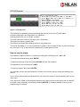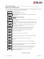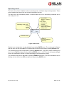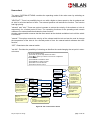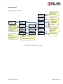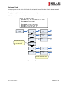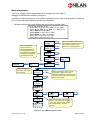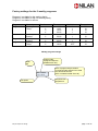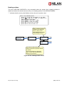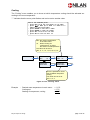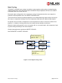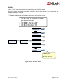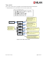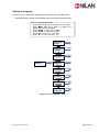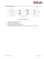
1
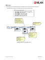
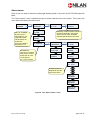
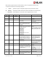
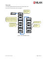
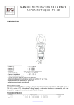
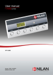
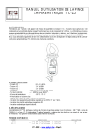
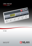
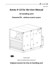
User manual CTS 602 by Nilan VPL 28 Version: 10.00, 13-04-2015 Software-version: 2.30 Table of contents Table of contents ............................................................................................................................ 2 Figure table .................................................................................................................................... 2 Introduction..................................................................................................................................... 3 Review of the thermometer sensors ............................................................................................... 4 CTS 602 panel ............................................................................................................................... 5 How to use the menu: ................................................................................................................. 5 Review of the menus ...................................................................................................................... 6 Menus in the CTS 602 control ..................................................................................................... 6 Operating mode .............................................................................................................................. 7 Main menu .................................................................................................................................. 8 Show alarms ............................................................................................................................... 9 Show data ................................................................................................................................. 12 User select ................................................................................................................................ 13 User select 2 ............................................................................................................................. 14 Setting of clock.......................................................................................................................... 15 Week programme ..................................................................................................................... 16 Factory settings for the 3 weekly programs: .............................................................................. 17 Cooling ..................................................................................................................................... 19 Night Cooling ............................................................................................................................ 20 Humidity .................................................................................................................................... 21 Air exchange ............................................................................................................................. 22 Air filter ..................................................................................................................................... 23 Temp. control ............................................................................................................................ 24 Setting of language ................................................................................................................... 25 System dimensions ...................................................................................................................... 26 Accessories/spare parts ............................................................................................................... 27 Figure table Figure 1: Thermometer sensors ...................................................................................................... 4 Figure 2: CTS 602 panel................................................................................................................. 5 Figure 3: Menu headlines ............................................................................................................... 6 Figure 4: Main menu ....................................................................................................................... 7 Figure 5: Headlines in the ”Main menu” .......................................................................................... 8 Figure 6: The ”Show alarms” menu................................................................................................. 9 Figure 7: The ”Show data” menu .................................................................................................. 12 Figure 8: The ”User select" menu ................................................................................................. 13 Figure 9: The ”User select 2" menu .............................................................................................. 14 Figure 10: Setting of clock ............................................................................................................ 15 Figure 11: The ”Week program” menu .......................................................................................... 16 Figure 12: The ”Heating surface” menu ........................................................................................ 18 Figure 13: The ”Cooling” menu ..................................................................................................... 19 Figure 14: The ”Night Cooling” menu ............................................................................................ 20 Figure 15: The ”Humidity" menu ................................................................................................... 21 Figure 16: The ”Air exchange” menu ............................................................................................ 22 Figure 17: The ”Air filter” menu ..................................................................................................... 23 Figure 18: The ”Temp. control” menu ............................................................................................ 24 Figure 19: The ”Language” menu ................................................................................................. 25 Figure 20: System dimensions...................................................................................................... 26 Introduction Please control that the following documents have been delivered together with the unit: - Directions for assembly and use - CTS 602 directions (this document) - Electrical chart The purpose of this manual is to clearly show the menus and possibilities of the CTS 602 control. This manual may describe functions that are not accessible in your unit. PLEASE NOTE: If the system is damaged in any way, it must be inspected and repaired by licensed personnel. May be subject to change page 3 of 27 Review of the thermometer sensors Figure 1: Thermometer sensors Explanation for figure 1: T1 - is the thermometer sensor for the fresh air and should be placed at the north side of the building. T2 - is the thermometer sensor for the inlet air at the fan (without heating surface). T5 - shows the temperature of the condenser. T6 - shows the temperature of the evaporator. T7 - is the thermometer sensor for the inlet air after a heating surface. T10 - is the thermometer sensor for the exhaust air in a room (accessory). T15 - is the thermometer sensor in the CTS 602 panel. The temperature of the sensors can be read in the “Show data” menu. May be subject to change page 4 of 27 CTS 602 panel Use of t he CTS 600 panel : - pr ess ESC t o go one st ep back i n t he menu - pr ess qpt o move up or down i n a menu or t o adj ust an act i vat ed menu - pr ess ENTER t o act i vat e a menu - pr ess ENTER t o conf i r m a menu - pr ess OFF t o t ur n of f t he uni t - pr ess ON t o t ur n t he uni t on Figure 2: CTS 602 panel The following is indicated by the light-emitting diode at the front of the CTS 602 panel: Constant yellow light: the compressor is in operation Flashing yellow: the unit is in alarm condition The panel can show 2 lines of text with each 8 characters. The upper line shows a guiding text. The bottom line shows the matching values to the guiding text. The text in the display in “on” as long as there is power to the unit and will not turn off even though the unit is set to “off” or has not been operated for a longer period of time. How to use the menu: It is possible to adjust a value or a function by finding the matching menu via p or q. To activate the desired menu press ENTER. To adjust the settings of the value press ENTER until the value flashes. The adjustment can now be done viapq. To save the chosen value press ENTER. It is advisable to have the panel and/or the review of the menus near by during the reading of the menus. If none of the press buttons are activated for one minute the control will automatically return to the main menu. If you are in the middle of the programming when the control returns to the main menu all data will be saved if they previously are saved by pressing ENTER. It is always possible to return to the programming to continue. May be subject to change page 5 of 27 Review of the menus Menus in the CTS 602 control The control will have the main menu as starting point, (the menu in the full-drawn frame). From here it is possible to go through the other menus via pq. SHOW ALARMS Alarm display and reset. Alarm log containing the latest 16 alarms. SHOW DATA Operating mode (heat, auto, cool), temperatures, fan speed, type of unit and software version. AUTO >2< 19°C Main menu: displays operating status . Press ESC to return to the main menu . USER SELECT Options: exhaust, inlet, ventilation, OFF. The function selected is activated via a switch or pressure. 10-09-13 TM .. 12:10 Date and time settings. The time and date must be reset if the system has been without power for more than24 hours. Summer and winter time must also be set manually. WEEK PROGRAM Weekly program can be set to ON or OFF. When the program is active, 1, 2 or 3 is displayed in the main menu . HEATING SURFACE The system has a heating surface installed . The heating surface can be chosen ON/OFF. Frost-protection is still active when OFF is chosen . COOLING Option for choosing a higher ventilation level when the system is cooling via open bypass valve . NIGHT COOLING Setting of the temperature for passive cooling at night HUMIDITY Offers the option to set a higher /lower fan speed at a high /low humidity level CO 2 The menu is only accessible when the unit has CO2-sensors installed AIR EXCHANGE Option for choosing a low ventilation level at a low outside temperature . AIR FILTER The controls are factory set to activate a filter alarm every 90 days. The alarm is reset in the VIEW ALARMS menu . TEMP. CONTROL Setting the minimum temperature required in order for the bypass valve to close. Maximum inlet air temperature can be set for a heating element . LANGUAGE ENGLISH Select the required language:English, German, French, Swedish, Danish, Norwegian or Finnish. Figure 3: Menu headlines May be subject to change page 6 of 27 Operating mode The main menu shows 3 different values: operating mode, ventilation step and temperature. Those values indicate the state of the unit and are selected by the user. The main menu is automatically shown 15 seconds after the unit is electrically connected and is now ready to be set. * : the ”USER SELECT” menu is active 1,2,3 : week programme is active L: low ventilation step at low outdoor temperature Operating mode: OFF AUTO COOL HEAT AUTO >2< * 19°C Ventilation step Desired roomtemperature (5-30°C). Figure 4: Main menu Desired room temperature can be adjusted by pressing ENTER once. The number at °C flashes and the value can be set via pq. The desired value must be approved by pressing ENTER once. The operating mode can be adjusted by pressing ENTER twice. The actual mode is flashing and can be set via pq and approved by pressing ENTER once. In “AUTO”-mode the bypass-draught control is automatically opened or closed according to the temperature setting. The ventilation step can be adjusted by pressing ENTER three times. The actual ventilation step is flashing and can be set via pq and approved by pressing ENTER once. May be subject to change page 7 of 27 Main menu The main menu is automatically shown 15 seconds after the unit is electrically connected. ” ” indicates that the menu point flashes and can be set to another value. Use of t he CTS 600 panel : - pr ess ESC t o go one st ep back i n t he menu - pr ess qpt o move up or down i n a menu or t o adj ust an act i vat ed menu - pr ess ENTER t o act i vat e a menu - pr ess ENTER t o conf i r m a menu - pr ess OFF t o t ur n of f t he uni t - pr ess ON t o t ur n t he uni t on In AUTO mode the unit automatically choses cooling or heating according to the desired room temperature. Week programme is possible. AUTO >2< 19°C ENTER AUTO >2< ”19°C” AUTO >2< ”5-30°C” The indicated ventilation step applies for the exhaust. ENTER ”AUTO” >2< 19°C ”COOLING” >2< 19°C ”HEAT” >2< 19°C Heating according to the desired room temperature. Week programme is NOT optional. ENTER AUTO ”>2<” 19°C AUTO ”>3<” 19°C Cooling according to the desired room temperature + neutral zone (+5 °C). Week programme is NOT optional. Figure 5: Headlines in the ”Main menu” May be subject to change page 8 of 27 Show alarms If the unit is in a state of alarm the yellow light-emitting diode on the front of the CTS 602 panel will flash. The ”Show alarms” menu indicates the type of alarm and the time of the alarm. This is also the menu where the alarm should be reset. SHOW ALARMS ENTER ALARM 6 DEFROST LIST OF ALARMS: Shows from 0-3 active alarms. The newest and most critical alarms are shown first. The list is erased if the power is cut. ALARM 19 FILTER ALARM 8 FROST ALARMLOG ALARMLOG: The log is recovered after power cut and shows the 16 most recent alarms AL 1 is the newest. ENTER 06-05-30 TI 11:32 ENTER 00-00-00 TI 00:00 Resetting of alarms:Alarms should be reset individually. Only active alarms can be reset. ALARM0 indicates that all alarms are reset. ENTER AL 1: 6 DEFROST ENTER 06-05-30 TI 10:28 AL 2: 19 FILTER STATUS ALARM AL 3: 8 FROST T1 20°C T2 20°C T3 T4 0,00 0,00 ALARMLOGDATA: Snapshots from the time of the alarm. OUT 1-8 00000000 OUT 9-16 00000000 OUT 17-24 00000000 Figure 6: The ”Show alarms” menu May be subject to change page 9 of 27 Alarm codes are given because of a fault situation or when it is important to inform the user. The alarms are divided into the following categories: C Critical W Warning I Informative Operation is partly or completely stopped as long as the alarm is active. These types of alarms will become critical if the problem is not solved quickly. Normal operation is not affected. Alarm disappears when it is reset. Alarm code Categori Text in display 00 -- -- 01 C HARDWARE 02 C TIMEOUT 03 C FIRE 04 C PRESSURE 06 C DEFROST 07 C FROST 08 C FROST 10 C OVERHEAT 11 C AIRFLOW 12 C TERMO May be subject to change Description/ cause How to remedy alarms No alarms Error in control hardware Warning alarm W has become a critical alarm. Fire detecting thermostat. Unit is stopped because the fire detecting thermostat has been activated. High or low pressure switch in the cooling circuit has been triggered, probably caused by: High pressure: Extreme hot Cloaked filter Defective fan Low pressure: Extreme cold Unit might have lost coolant Cloaked filter Defective fan The unit is defrosting. The frost protection of the heat recovery system is insufficient and the unit will stop. This can be caused by extreme low outdoor temperatures The water from the central heating is too cold. One of the temperature sensors in the unit is short circuit or defect. The electrical heating element is overheated. Lack of airflow due to cloaked filters, cloaked air intake or defect inlet fan. Lacking inlet airflow Relay is triggered ventilation. This may be due to defects in the fan or low voltage Contact service if reset does not help Note and reset the alarm. Contact service if alarm does not disappear. If there has not been a fire please contact service. Check for errors and reset alarms. If you are unable to reset the alarm or if the alarm occurs often please contact service. Contact service if reset does not help. Note the actual sensor temperatures from the menu “Show data” to help service. Check that the heating supply for the heating surface is OK. Reset alarm when fault has been repaired. Note the sensor and contact service. Check if air flows into the house. Check filter and air intake. Reset alarm. Contact service if the above does not help. See alarm code 10 Contact service page 10 of 27 Alarm code Categori Text in display Description/ cause 15 W ROOM LOW 16 17 18 I I I SOFTWARE WATCHDOG CONFIG When room temperature drops below 10°C the unit will stop in order to protect the house from further cooling down. The function is useful when the house is not occupied and the main heating has stopped. Error in software Error in software Parts of the programming are lost and can be caused by a longer period of power failure or lightning. The unit will keep on operating on standard programming. 19 I FILTER 21 I POWER 22 I T AIR 27-57 C T x KURZ 28-58 C T x OFFEN One of the temperature sensor of the device is disconnected or defect Tx= -40 ° C 71 I DFR EXCH The maximum defrosting time for the counter flow heat exchanger has been exceeded. This could be due to the fact that the system has been exposed to very low temperatures. 72 I EVAP LOW 92 I PRESET Abnormally low evaporator temperature Error by writing or input of the electrician’s adjustments May be subject to change The filter guard is set to give alarm when a pre-set period of time has occurred Occurs if power has been cut off for a longer period of time The pre-set temperature of the inlet air cannot be reached One of the temperature sensor of the device is shorted or defective.Tx = +99 °C How to remedy alarms Heat up the house and reset the alarm Contact service Contact service Reset alarm Re-programme the week programme. Contact service if the unit does not operate as before. Supplementary programs can be lost. Only service can access the supplementary programs and menus. Clean /replace filter and reset alarm The week programme should be checked and adjusted if necessary. Reset alarm. Set a lower air inlet temperature and reset alarm. Please note which sensor T x, there is shorted, and contact the customer service. Please note which sensor T x, there is interruped, and contact the customer service. Contact our after sales department if resetting the alarm does not help. If possible, inform the after sales department of the current working temperature from the menu VIS DATA (SHOW DATA). Check supply air valve Contact service. page 11 of 27 Show data The actual operation data can be read in the ”Show data” menu. See review of thermometer sensors at page 5. SHOW DATA ENTER STATUS HEATING Room temperature recorded by T15 (sensor in CTS 600 control panel). PANEL T15 20°C T10 is an external sensor that can be installed in an exhaust fitting in the sitting area. T10 can be chosen as a controlling room sensor in the service menu. See the installation instruction For systems without heating element, T2 is shown. For systems with heating element, T7 is shown. EXTERNAL 9 °C T10 WATER T9 25 °C HUMIDITY 100 % INLET FLOW INLET T7 50 °C EXHAUST FLOW 3 FRESHAIR T1 40 °C SOFTWARE 1 2.21 COND T5 25 °C SOFTWARE 2 1.02 EVAP T6 TYPE VPM/28EC 40 °C 3 The software version used by the system. The software version used by the controls. Figure 7: The ”Show data” menu May be subject to change page 12 of 27 User select The menu CUSTOM OPTIONS overrides the operating mode of the main menu by activating an external switch. ”VENTILAT”: There is a possibility here to run with a higher or lower speed on the air exhaust and air inlet for a limited amount of time. The external pressure will activate the function. The function has high priority. ”exhaust” and ”inlet”: These two options increase or reduce the velocity of the exhaust or inlet air respectively for a limited period of time. The remaining functions of the operating mode remain unaltered. An external switch activates the timer function. Another external switch ensures that the fans remain at the desired ventilation level until the switch is turned off. ”extend”: This option controls the velocity of the exhaust and inlet air and can be used to change the temperature of the inlet air for a limited period of time. An external switch activates the timer function. “OFF”: Deactivates the external switch. ”ext offs”: Provides the possibility of choosing an afterflow time and changing the set point in external rooms. Use of the CTS602 panel: - press ESC to go one step back in the menu - press qpto move up or down in a menu or to adjust an activated menu - press ENTER to activate a menu - press ENTER to confirm a menu - press OFF to turn off the unit - press ON to turn the unit on SELECT ”VENTILAT” ENTER SELECT ENTER ”EXT OFFS” USER SELECT ENTER SELECT ”EXTEND” Required period in which the selected function is to remain operative: stated in hours and minutes. Max 8 hours. ENTER TIME ENTER FLOW ”00:00" ENTER FLOW ENTER TEMP ”>4<” >4< TEMP 23°C Required ventilation step: 1-4. OFF allows the system to be shut down via an external switch. TIME 00:00 ”23" °C SELECT ”EXHAUST” ENTER SELECT ”INLET” ENTER Choose the afterrunning and displacement of the setpunkt, for externak heating. See SELECT EXTEND Time and speed must be set in the same way as described under SELECT EXTEND. SELECT ”EXTEND” SELECT ”OFF” Possibility to run at a higher or lower rate. High priority. ENTER Switches user option off. Required room temperature (5-30°C). T15 is the temperature sensor to be used to control the system. Figure 8: The ”User select" menu May be subject to change page 13 of 27 User select 2 User select 2 as user select SELECT ”VENTILAT” ENTER SELECT ENTER ”EXT OFFS” USER SELECT ENTER SELECT ”EXTEND” Required period in which the selected function is to remain operative: stated in hours and minutes. Max 8 hours. TIME ENTER TIME ”00:00" 00:00 FLOW ENTER FLOW ENTER TEMP ”>4<” >4< TEMP 23°C Required ventilation step: 1-4. OFF allows the system to be shut down via an external switch. ENTER ”23" °C SELECT ”EXHAUST” ENTER SELECT ”INLET” ENTER Choose the afterrunning and displacement of the setpunkt, for externak heating. See SELECT EXTEND Time and speed must be set in the same way as described under SELECT EXTEND. SELECT ”EXTEND” SELECT ”OFF” Possibility to run at a higher or lower rate. High priority. ENTER Switches user option off. Required room temperature (5-30°C). T15 is the temperature sensor to be used to control the system. Figure 9: The ”User select 2" menu May be subject to change page 14 of 27 Setting of clock In case of power cut the clock will function for at least 24 hours. If the time function is lost there will be a alarm. Changing to daylight saving time has to be done manually. ” ” indicates that the menu point flashes and can be set to another value. Use of t he CTS 600 panel : - pr ess ESC t o go one st ep back i n t he menu - pr ess qpt o move up or down i n a menu or t o adj ust an act i vat ed menu - pr ess ENTER t o act i vat e a menu - pr ess ENTER t o conf i r m a menu - pr ess OFF t o t ur n of f t he uni t - pr ess ON t o t ur n t he uni t on 06-05-30 TI 12.10 ENTER YEAR ENTER 06 ENTER YEAR ”06" ENTER 05 ENTER MONTH ”05" ENTER DAY ”30" ENTER 30 ENTER HOUR ”12" ENTER 12 ENTER MINUTE ”10" ENTER 10 MONTH DAY Is only shown the first time after setting up the time function. WEEK DAY 2 HOUR MINUTE Seconds are being reset when minutes are adjusted Figure 10: Setting of clock May be subject to change page 15 of 27 Week programme The unit is equipped with 3 standardized week programmes. See page 17. Anlægget er fra fabrikken indstillet til program 1. In addition to these programmes it is possible to programme your own week programme which can be one of the standard programmes with minor alterations. ” ” indicates that the menu point flashes and can be set to another value. Use of t he CTS 600 panel : - pr ess ESC t o go one st ep back i n t he menu - pr ess qpt o move up or down i n a menu or t o adj ust an act i vat ed menu - pr ess ENTER t o act i vat e a menu - pr ess ENTER t o conf i r m a menu - pr ess OFF t o t ur n of f t he uni t - pr ess ON t o t ur n t he uni t on Here it is possible to chose one of the 3 standard programmes. The 3 programmes can be altered but not deleted. The original programme can always be found. WEEK PROGRAM ENTER SELECT OFF System operation in accordance with main menu settings SELECT ”CLEAR” ENTER SELECT ”PROG 3" ENTER SELECT ”PROG 2" ENTER SELECT ”PROG 1" ENTER SELECT PROG 1 ENTER ENTER SELECT ”OFF” MO1 06.00 >3 < 21°C ENTER MO2 08.00 >1 < 17°C ENTER Here it is possible to delete all user made programmes. The unit will continue in AUTO mode without any week programme. Here it is possible to make your own programme or adjust one of the standard programmes. If there is more than one function at the same time only the last one is active. MO 3 AUS >1 < 17°C MO4-6 MO TU COPY TU1 06.00 >3 < 21°C TU2-6 ENTER MO TU ”COPY” ENTER TU WE COPY ENTER Once settings have been made for Monday , the values can be copied to any other day the same settings are to apply using in the copy function. Figure 11: The ”Week program” menu May be subject to change page 16 of 27 Factory settings for the 3 weekly programs: Program 1 is suitable for the working family Program 2 is suitable for the non-working family Program 3 is suitable for offices Program Program 1 Program 2 Program 3 Week day Monday Friday Saturday Sunday Monday Sunday Monday Friday Function 1 2 3 4 1 2 1 2 1 2 Time 6.00 8.00 15.00 22.00 8.00 23.00 8.00 23.00 7.00 16.00 Ventilation 3 1 3 1 3 1 3 1 3 OFF Temperature 21 21 21 21 21 21 21 21 21 21 Weekly program settings Week day. Program step. 6 program steps are available each day. MO 1 08.00 >1< 17°C Fan speed. May be subject to change Time of program step activation. If a program step should not be used OFF should be chosen. (OFF is located instead of 24.00) Required room temperature. page 17 of 27 Heating surface The menu HEATING SURFACE is only accessible when the system has a heating surface installed and when the control has been set up to a heating surface in the SERVICE MENU. ” ” indicates that the menu point flashes and can be set to another value. Use of t he CTS 600 panel : - pr ess ESC t o go one st ep back i n t he menu - pr ess qpt o move up or down i n a menu or t o adj ust an act i vat ed menu - pr ess ENTER t o act i vat e a menu - pr ess ENTER t o conf i r m a menu - pr ess OFF t o t ur n of f t he uni t - pr ess ON t o t ur n t he uni t on When a heating surface is installed T2 is replaced with T7, which is the sensor placed in the inlet at the heating surface. HEATING SURFACE ENTER SELECT ON ENTER SELECT ”ON” ENTER SELECT ”OFF” ENTER If you wish to disconnect the heating surface this position should be chosen. The frost-protection is still active and T7 is the active temperature sensor for the inlet air. Figure 12: The ”Heating surface” menu May be subject to change page 18 of 27 Cooling The ”Cooling” menu enables you to chose at which temperature cooling should be activated according to the room temperature. ” ” indicates that the menu point flashes and can be set to another value. Use of t he CTS 600 panel : - pr ess ESC t o go one st ep back i n t he menu - pr ess qpt o move up or down i n a menu or t o adj ust an act i vat ed menu - pr ess ENTER t o act i vat e a menu - pr ess ENTER t o conf i r m a menu - pr ess OFF t o t ur n of f t he uni t - pr ess ON t o t ur n t he uni t on SET: the chosen temperature in the main menu. +5: allows cooling via compressor 5 °C above the chosen roomtemperature The value can be set to: OFF, 0, +1, +2, +3,+4,+5,+7,+10. COOLING ENTER TEMP SET +3 VENTILAT HIGH OFF ENTER TEMP ”SET +3” ENTER ENTER VENTILAT HIGH ”OFF” ENTER Here it is possible to chose high ventilation step when cooling. The value can be set to: OFF, 2, 3, 4. Figure 13: The ”Cooling” menu Example : Desired room temperature in main menu Cooling set Starting of compressor, cooling May be subject to change = 21°C = 5°C = 26°C page 19 of 27 Night Cooling The NIGHT COOLING menu makes it possible to select passive night cooling, provided that the outdoor temperature on the day before has exceeded the day temperature limit set in the NIGHT COOLING menu for at least one hour. During the night cooling period, the compressor cooling is suspended and the room setpoint is lowered to the temperature set in the NIGHT COOLING menu. The limit set for the minimum intake temperature is not observed during night cooling, but the system may run compressor heating if the room temperature falls below the night cooling setpoint. No special account is taken of whether the room temperature is above or below the outdoor temperature, i.e. whether a cooling effect from the outdoor air can actually be achieved. When the night cooling period is over, the system will run as normal again, with compressor heating and cooling according to the normal setpoint. Outdoor temperature as requirement NIGHT COOLING New ROOM SET for NIGHT COOLING Outdoor temperature as requirement NIGHT COOLING OFF, 20….40°C NIGHT COOLING ENTER DAY TEMP ENTER DAY TEMP 25 °C ”25 °C” ENTER ENTER ROOM SET ”18 °C” ENTER ROOM SET 18 °C New ROOM SET for NIGHT COOLING OFF, 20….40°C Figure 14: The ”Night Cooling” menu May be subject to change page 20 of 27 Humidity In the “Humidity” menu it is possible to regulate the ventilation step in accordance with the humidity level. Low ventilation step is only active in wintertime and at humidity levels below 30%. High step is activated by a change from 10-5% of average RH from 40-80% over the last 24 hours High ventilation step is deactivated when humidity drops 3% or more compared to the average humidity level the last 24 hours. It can last up to 3 minutes before high/low ventilation step i stabilized. If there is a need for heat the "low humidity" is not activated. ” ” indicates that the menu point flashes and can be set to another value. Use of the CTS602 panel: - press ESC to go one step back in the menu - press qpto move up or down in a menu or to adjust an activated menu - press ENTER to activate a menu - press ENTER to confirm a menu - press OFF to turn off the unit - press ON to turn the unit on Option of choosing low ventilation step at low humidity. The value can be set to: OFF and 1, 2, 3, . HUMIDITY ENTER FLOW LOW 1 LOW ENTER HUMIDITY LOW ”1" ENTER ENTER LOW ENTER ”30"% 30% FLOW HIGH TIME 0 4 MIN Adjustable range between 15...45% Standard is 30 % ENTER FLOW HIGH ENTER TIME 0 " ENTER ”4” ENTER MIN Option of choosing high ventilation step at high humidity. The value can be set to: OFF and 2, 3, 4. Maximal duration for high ventilation step caused by high humidity. Figure 15: The ”Humidity" menu May be subject to change page 21 of 27 Air exchange In the ”Air exchange” menu it is possible to chose between 2 different types of ventilation depending on your individual demand. ” ” indicates that the menu point flashes and can be set to another value. Use of t he CTS 600 panel : - pr ess ESC t o go one st ep back i n t he menu - pr ess qpt o move up or down i n a menu or t o adj ust an act i vat ed menu - pr ess ENTER t o act i vat e a menu - pr ess ENTER t o conf i r m a menu - pr ess OFF t o t ur n of f t he uni t - pr ess ON t o t ur n t he uni t on AIR EXCH ”COMFORT” AIR EXCHANGE ENTER AIR EXCH ENERGY Start temperature for the curve regulation of the inlet air volume. The value is preset to 38°C and can be set between 28 °C and 43 °C ENTER AIR EXCH ”ENERGY” ENTER CURVE MIN 38°C ENTER ENTER CURVE MAX 35°C ENTER CURVE MIN ”38°C” WINTER LOW ”OFF” WINTER LOW ”1” WINTER LOW ”2” WINTER LOW ”3” In COMFORT mode the air exchange is balanced. This ensures the rigth level of ventilation chosen by the user. ENERGY mode secures an energy optimized operation by adjusting the inlet air volume according to the setting of the curve value. When using curve regulation the inlet air will always be warm. When regulating the inlet airflow down when the heat recovery from the heat pump is not adequate it is possible to keep the inlet air warm. The inlet fan can stop if necessary especially when a large quantity of hot water is needed. WINTER LOW OFF Possibility of low ventilation step at low outdoor Temperatures. The value can be set to OFF, 1,2,3. ENTER ENTER WINTER LOW 1 WINTER 2 °C < Outdoor temperature at which low ventilation step is activated. Figure 16: The ”Air exchange” menu May be subject to change page 22 of 27 Air filter In the ”Air filter” menu it is possible to chose the interval of the filter guard. The unit is factory configured to provide emergency with 90 days interval. It is then possible to change this range if necessary. ” ” indicates that the menu point flashes and can be set to another value. Use of t he CTS 600 panel : - pr ess ESC t o go one st ep back i n t he menu - pr ess qpt o move up or down i n a menu or t o adj ust an act i vat ed menu - pr ess ENTER t o act i vat e a menu - pr ess ENTER t o conf i r m a menu - pr ess OFF t o t ur n of f t he uni t - pr ess ON t o t ur n t he uni t on AIR FILTER ENTER ALARM 90 DAYS ALARM ” GUARD+70D” ENTER ALARM ” 360 DAYS” ENTER ALARM ” 180 DAYS” ENTER ENTER ALARM ” 90 DAYS” ENTER ALARM ” 30 DAYS” ENTER ALARM ”GUARD” ENTER Suggestion for the settings of the filter guard: 2 x pressure drop when filters are clean or as desired Figure 17: The ”Air filter” menu May be subject to change page 23 of 27 Temp. control In the ”Temp. control” menu it is possible to set the highest and lowest inlet temperature. ” ” indicates that the menu point flashes and can be set to another value. Use of t he CTS 600 panel : - pr ess ESC t o go one st ep back i n t he menu - pr ess qpt o move up or down i n a menu or t o adj ust an act i vat ed menu - pr ess ENTER t o act i vat e a menu - pr ess ENTER t o conf i r m a menu - pr ess OFF t o t ur n of f t he uni t - pr ess ON t o t ur n t he uni t on TEMP. CONTROL These are only shown in the panel if the unit has a heating surface. ENTER SUMMER ”MIN 14°C” ENTER WINTER ”MIN 16°C” ENTER SUMMER MAX ”22°C” ENTER WINTER MAX ”24°C” ENTER SUMMER ”12°C” ENTER Cooling via compressor is allowed at outdoor temperatures higher than the preset value. Can be set from 10-16°C Cooling via compressor is allowed at outdoor temperatures higher than the preset value. Can be set from 14-22°C Highest possible inlet temperature in summer. Can be set from 16-25 °C. Highest possible inlet temperature in winter. Can be set from 22-50 °C. Lowest out-door temperature in order for the unit to operate according to summer temperatures. Figure 18: The ”Temp. control” menu May be subject to change page 24 of 27 Setting of language In this menu you set which language to be used in the CTS 602 panel. ” ” indicates that the menu point flashes and can be set to another value. Use of t he CTS 600 panel : - pr ess ESC t o go one st ep back i n t he menu - pr ess qpt o move up or down i n a menu or t o adj ust an act i vat ed menu - pr ess ENTER t o act i vat e a menu - pr ess ENTER t o conf i r m a menu - pr ess OFF t o t ur n of f t he uni t - pr ess ON t o t ur n t he uni t on LANGUAGE ”CZECH” LANGUAGE DANISH ENTER ENTER LANGUAGE ”SUOMI” ENTER LANGUAGE ”NORWEG.” ENTER LANGUAGE ”DANISH” ENTER LANGUAGE ”SWEDISH” ENTER LANGUAGE ”FRENCH” ENTER LANGUAGE ”GERMAN” ENTER LANGUAGE ”ENGLISH” ENTER Figure 19: The ”Language” menu May be subject to change page 25 of 27 System dimensions Figure 20: System dimensions 1: 2: 3: 4: 11: Udeluft, Fresh Air, Aussenluft, Air neuf Tilluft, Air Inlet, Zuluft, Air pulse Fraluft, Air Exhaust, Abluft, Air repris Afkastluft, Air Discharge, Fortluft, Air extrait Kondensafløb, Evacuation condersats, Kondensatmuffe, Vacuation des condensats May be subject to change page 26 of 27 Accessories/spare parts VPL 28 Filter types Duct filter Qty. 1 Nilan item no. 85063 Heating surface, water Unit VPL 28 Qty. 1 Nilan item no. 768983Z Heating surface, electrical Unit VPL 28 Qty. 1 Nilan item no. 764231 Qty. 1 Nilan item no. 3932 Filter FU Unit FU28H Designation Ø250mm Filterclass G4 Designation Pladefilter (1 sæt) Heating cable for condensation outlet (frost protection) System System type VPL 28 Heating cable May be subject to change Nilan Item no. 2172 page 27 of 27