1
MELSEC Data Link Library
Reference Manual
-Q80BD-J61BT11N
-Q81BD-J61BT11
-Q80BD-J71LP21-25
-Q80BD-J71LP21S-25
-Q81BD-J71LP21-25
-Q80BD-J71LP21G
-Q80BD-J71BR11
-Q80BD-J71GP21-SX
-Q80BD-J71GP21S-SX
-Q81BD-J71GP21-SX
-Q81BD-J71GP21S-SX
-Q80BD-J71GF11-T2
-Q81BD-J71GF11-T2
SAFETY PRECAUTIONS
(Read these precautions before using this product.)
Before using this product, please read this manual and the relevant manuals carefully and pay full attention
to safety to handle the product correctly.
Make sure that the end users read this manual and then keep the manual in a safe place for future
reference.
1
CONDITIONS OF USE FOR THE PRODUCT
(1) Mitsubishi programmable controller ("the PRODUCT") shall be used in conditions;
i) where any problem, fault or failure occurring in the PRODUCT, if any, shall not lead to any major
or serious accident; and
ii) where the backup and fail-safe function are systematically or automatically provided outside of
the PRODUCT for the case of any problem, fault or failure occurring in the PRODUCT.
(2) The PRODUCT has been designed and manufactured for the purpose of being used in general
industries.
MITSUBISHI SHALL HAVE NO RESPONSIBILITY OR LIABILITY (INCLUDING, BUT NOT
LIMITED TO ANY AND ALL RESPONSIBILITY OR LIABILITY BASED ON CONTRACT,
WARRANTY, TORT, PRODUCT LIABILITY) FOR ANY INJURY OR DEATH TO PERSONS OR
LOSS OR DAMAGE TO PROPERTY CAUSED BY the PRODUCT THAT ARE OPERATED OR
USED IN APPLICATION NOT INTENDED OR EXCLUDED BY INSTRUCTIONS, PRECAUTIONS,
OR WARNING CONTAINED IN MITSUBISHI'S USER, INSTRUCTION AND/OR SAFETY
MANUALS, TECHNICAL BULLETINS AND GUIDELINES FOR the PRODUCT.
("Prohibited Application")
Prohibited Applications include, but not limited to, the use of the PRODUCT in;
• Nuclear Power Plants and any other power plants operated by Power companies, and/or any
other cases in which the public could be affected if any problem or fault occurs in the PRODUCT.
• Railway companies or Public service purposes, and/or any other cases in which establishment of
a special quality assurance system is required by the Purchaser or End User.
• Aircraft or Aerospace, Medical applications, Train equipment, transport equipment such as
Elevator and Escalator, Incineration and Fuel devices, Vehicles, Manned transportation,
Equipment for Recreation and Amusement, and Safety devices, handling of Nuclear or
Hazardous Materials or Chemicals, Mining and Drilling, and/or other applications where there is a
significant risk of injury to the public or property.
Notwithstanding the above, restrictions Mitsubishi may in its sole discretion, authorize use of the
PRODUCT in one or more of the Prohibited Applications, provided that the usage of the PRODUCT
is limited only for the specific applications agreed to by Mitsubishi and provided further that no
special quality assurance or fail-safe, redundant or other safety features which exceed the general
specifications of the PRODUCTs are required. For details, please contact the Mitsubishi
representative in your region.
2
INTRODUCTION
Thank you for purchasing the PC interface board.
This manual describes the programming procedure and function specifications of the MELSEC data link library.
Before using this product, please read this manual and the related manuals carefully and develop familiarity with the
functions and performance of the MELSEC data link library to handle the product correctly.
Please make sure that the end users read this manual.
RELATED MANUALS
The following are the manuals relevant to this product.
Refer to the following tables when ordering required manuals.
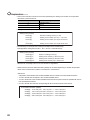
(1) Related manuals of CC-Link Ver.2 board
Manual name
Description
<Manual number (model code)>
Type Q80BD-J61BT11N/Q81BD-J61BT11 CC-Link System
Master/Local Interface Board User's Manual
(For SW1DNC-CCBD2-B)
<SH-080527ENG, 13JR77>
MELSEC-L CC-Link System Master/Local Module User's
Manual
<SH-080895ENG, 13JZ41>
MELSEC-Q CC-Link System Master/Local Module User's
Manual
<SH-080394E, 13JR64>
CC-Link System Master/Local Module Type
AJ61BT11/A1SJ61BT11 User's Manual
<IB-66721, 13J872>
CC-Link System Master/Local Module Type
AJ61QBT11/A1SJ61QBT11 User's Manual
<IB-66722, 13J873>
Overview of system configuration, specifications, functions, handling,
wiring, and troubleshooting for type Q80BD-J61BT11N
/Q81BD-J61BT11 CC-Link system master/local interface board.
Overview of system configuration, performance specifications, functions,
handling, wiring, and troubleshooting for L series master/local modules.
Overview of system configuration, performance specifications, functions,
handling, wiring, and troubleshooting for Q series master/local modules.
Overview of system configuration, performance specifications, functions,
handling, wiring, and troubleshooting for AJ61BT11 and A1SJ61BT11.
Overview of system configuration, performance specifications, functions,
handling, wiring, and troubleshooting for AJ61QBT11 and A1SJ61QBT11.
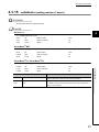
(2) Related manuals of MELSECNET/H board
Manual name
Description
<Manual number (model code)>
MELSECNET/H Interface Board User's Manual
(For SW0DNC-MNETH-B)
<SH-080128, 13JR24>
Overview of system configuration, specifications, functions, handling,
wiring, and troubleshooting for MELSECNET/H interface boards.
Q Corresponding MELSECNET/H Network System
Overview of system configuration, performance specifications, functions,
Reference Manual (PLC to PLC network)
handling, wiring, and troubleshooting for the MELSECNET/H network
<SH-080049, 13JF92>
system.
3
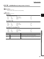
(3) Related manuals of CC-Link IE Controller Network board
Manual name
Description
<Manual number (model code)>
CC-Link IE Controller Network Interface Board User's Manual
Overview of system configuration, specifications, functions, handling,
(For SW1DNC-MNETG-B)
wiring, and troubleshooting for CC-Link IE Controller Network interface
<SH-080691ENG, 13JZ02>
MELSEC-Q CC-Link IE Controller Network Reference
Manual
<SH-080668ENG, 13JV16>
board.
Overview of system configuration, performance specifications, functions,
handling, wiring, and troubleshooting for CC-Link IE Controller Network.
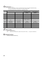
(4) Related manuals of CC-Link IE Field Network board
Manual name
Description
<Manual number (model code)>
CC-Link IE Field Network Interface Board User's Manual
(For SW1DNC-CCIEF-B)
<SH-080980ENG, 13JZ58>
MELSEC-Q CC-Link IE Field Network Master/Local Module
User's Manual
<SH-080917ENG, 13JZ47>
MELSEC-L CC-Link IE Field Network Master/Local Module
User's Manual
<SH-080972ENG, 13JZ54>
Overview of system configuration, specifications, functions, handling,
wiring, and troubleshooting for CC-Link IE Field Network interface board.
Overview of CC-Link IE Field Network, and specifications, procedures
before operation, system configuration, installation, wiring, settings,
functions, programming, and troubleshooting for MELSEC-Q series CCLink IE Field Network master/local module.
Overview of the CC-Link IE Field Network, and specifications, procedures
before operation, system configuration, installation, wiring, settings,
functions, programming, and troubleshooting for MELSEC-L series CCLink IE Field Network master/local modules.
MELSEC-L CC-Link IE Field Network Head Module User's
Overview of specifications, procedures before operation, system
Manual
configuration, installation, wiring, settings, and troubleshooting for head
<SH-080919ENG, 13JZ48>
module.
CC-Link IE Field Network Ethernet Adapter Module User's
Overview of specifications, procedures before operation, system
Manual
configuration, installation, wiring, settings, and troubleshooting for Ethernet
<SH-080939ENG, 13JZ50>
adapter module.
Remark
User's manuals of each type of boards are stored on the CD-ROM of the software package in a PDF file format.
Manuals in printed form are sold separately for a single purchase. Order a manual by quoting the manual number (model
code) listed in the above table.
4
Memo
5
CONTENTS
CONTENTS
SAFETY PRECAUTIONS . . . . . . . . . . . . . . . . . . . . . . . . . . . . . . . . . . . . . . . . . . . . . . . . . . . . . . . . . . . . . 1
CONDITIONS OF USE FOR THE PRODUCT . . . . . . . . . . . . . . . . . . . . . . . . . . . . . . . . . . . . . . . . . . . . . 2
INTRODUCTION . . . . . . . . . . . . . . . . . . . . . . . . . . . . . . . . . . . . . . . . . . . . . . . . . . . . . . . . . . . . . . . . . . . . 3
RELATED MANUALS . . . . . . . . . . . . . . . . . . . . . . . . . . . . . . . . . . . . . . . . . . . . . . . . . . . . . . . . . . . . . . . . 3
HOW TO READ THIS MANUAL . . . . . . . . . . . . . . . . . . . . . . . . . . . . . . . . . . . . . . . . . . . . . . . . . . . . . . . . 9
TERMS . . . . . . . . . . . . . . . . . . . . . . . . . . . . . . . . . . . . . . . . . . . . . . . . . . . . . . . . . . . . . . . . . . . . . . . . . . 10
CHAPTER 1 OVERVIEW
11
1.1
MELSEC Data Link Library. . . . . . . . . . . . . . . . . . . . . . . . . . . . . . . . . . . . . . . . . . . . . . . . . . . . 11
1.2
Supported Boards. . . . . . . . . . . . . . . . . . . . . . . . . . . . . . . . . . . . . . . . . . . . . . . . . . . . . . . . . . . 11
CHAPTER 2 PROGRAMMING
12
2.1
Programming Procedure. . . . . . . . . . . . . . . . . . . . . . . . . . . . . . . . . . . . . . . . . . . . . . . . . . . . . . 12
2.2
Precautions when Using MELSEC Data Link Library . . . . . . . . . . . . . . . . . . . . . . . . . . . . . . . . 13
2.2.1
Precautions when programming . . . . . . . . . . . . . . . . . . . . . . . . . . . . . . . . . . . . . . . . . . . . . . 13
2.2.2
Precautions when accessing own station link devices and other station's programmable
controller devices . . . . . . . . . . . . . . . . . . . . . . . . . . . . . . . . . . . . . . . . . . . . . . . . . 15
2.3
Settings for Using Functions. . . . . . . . . . . . . . . . . . . . . . . . . . . . . . . . . . . . . . . . . . . . . . . . . . . 17
2.3.1
Using Visual Basic®5.0, Visual Basic®6.0 . . . . . . . . . . . . . . . . . . . . . . . . . . . . . . . . . . . . . . . 17
2.3.2
Using Visual C++®5.0, Visual C++®6.0 . . . . . . . . . . . . . . . . . . . . . . . . . . . . . . . . . . . . . . . . . 18
2.3.3
Using Visual Basic®.NET . . . . . . . . . . . . . . . . . . . . . . . . . . . . . . . . . . . . . . . . . . . . . . . . . . . . 20
2.3.4
Using Visual C++®.NET 2003, Visual C++®2005, Visual C++®2008. . . . . . . . . . . . . . . . . . . 21
2.3.5
Using Visual C++®2010, Visual C++®2012 . . . . . . . . . . . . . . . . . . . . . . . . . . . . . . . . . . . . . . 23
2.3.6
Using Visual C++®2013 . . . . . . . . . . . . . . . . . . . . . . . . . . . . . . . . . . . . . . . . . . . . . . . . . . . . . 30
CHAPTER 3 ACCESSIBLE DEVICES AND RANGES
37
3.1
Access Target . . . . . . . . . . . . . . . . . . . . . . . . . . . . . . . . . . . . . . . . . . . . . . . . . . . . . . . . . . . . . . 37
3.2
Accessible Ranges . . . . . . . . . . . . . . . . . . . . . . . . . . . . . . . . . . . . . . . . . . . . . . . . . . . . . . . . . . 38
3.3
3.2.1
Access target on own network . . . . . . . . . . . . . . . . . . . . . . . . . . . . . . . . . . . . . . . . . . . . . . . . 38
3.2.2
Access target when connected via network . . . . . . . . . . . . . . . . . . . . . . . . . . . . . . . . . . . . . . 39
Accessible Devices. . . . . . . . . . . . . . . . . . . . . . . . . . . . . . . . . . . . . . . . . . . . . . . . . . . . . . . . . . 40
3.3.1
Access to link devices and buffer memory of own station . . . . . . . . . . . . . . . . . . . . . . . . . . . 40
3.3.2
Access to devices of QnA, Q, L, and R series module . . . . . . . . . . . . . . . . . . . . . . . . . . . . . 41
3.3.3
Access to devices of A series module . . . . . . . . . . . . . . . . . . . . . . . . . . . . . . . . . . . . . . . . . . 42
3.3.4
Access to Ethernet adapter module, Head module, and CC-Link IE Field remote device
station . . . . . . . . . . . . . . . . . . . . . . . . . . . . . . . . . . . . . . . . . . . . . . . . . . . . . . . . 43
3.3.5
Access to other station buffer memory of CC-Link. . . . . . . . . . . . . . . . . . . . . . . . . . . . . . . . . 43
3.3.6
Access using the SEND function or the RECV function. . . . . . . . . . . . . . . . . . . . . . . . . . . . . 44
CHAPTER 4 FUNCTIONS
4.1
4.2
6
45
List of Functions . . . . . . . . . . . . . . . . . . . . . . . . . . . . . . . . . . . . . . . . . . . . . . . . . . . . . . . . . . . . 45
Common Specifications of Functions . . . . . . . . . . . . . . . . . . . . . . . . . . . . . . . . . . . . . . . . . . . . 47
4.2.1
Specifying channel number . . . . . . . . . . . . . . . . . . . . . . . . . . . . . . . . . . . . . . . . . . . . . . . . . . 47
4.2.2
Specifying station numbers . . . . . . . . . . . . . . . . . . . . . . . . . . . . . . . . . . . . . . . . . . . . . . . . . . 48
4.2.3
Specifying network numbers and station numbers for extended functions . . . . . . . . . . . . . . 50
4.2.4
4.3
Specifying device types . . . . . . . . . . . . . . . . . . . . . . . . . . . . . . . . . . . . . . . . . . . . . . . . . . . . . 52
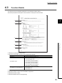
Function Details . . . . . . . . . . . . . . . . . . . . . . . . . . . . . . . . . . . . . . . . . . . . . . . . . . . . . . . . . . . . 55
4.3.1
mdOpen (opening communication lines) . . . . . . . . . . . . . . . . . . . . . . . . . . . . . . . . . . . . . . . . 56
4.3.2
mdClose (closing communication lines). . . . . . . . . . . . . . . . . . . . . . . . . . . . . . . . . . . . . . . . . 57
4.3.3
mdSendEx (batch writing extended devices / SEND function) . . . . . . . . . . . . . . . . . . . . . . . 58
4.3.4
mdReceiveEx (batch reading extended devices / RECV function) . . . . . . . . . . . . . . . . . . . . 62
4.3.5
mdRandWEx (writing extended devices randomly) . . . . . . . . . . . . . . . . . . . . . . . . . . . . . . . . 66
4.3.6
mdRandREx (reading extended devices randomly). . . . . . . . . . . . . . . . . . . . . . . . . . . . . . . . 69
4.3.7
mdDevSetEx (setting extended bit devices) . . . . . . . . . . . . . . . . . . . . . . . . . . . . . . . . . . . . . 73
4.3.8
mdDevRstEx (resetting extended bit devices) . . . . . . . . . . . . . . . . . . . . . . . . . . . . . . . . . . . . 75
4.3.9
mdRemBufWriteEx (writing data to buffer memory of remote device station) . . . . . . . . . . . . 77
4.3.10 mdRemBufReadEx (reading data from buffer memory of remote device station) . . . . . . . . . 79
4.3.11
mdTypeRead (reading model names of CPU) . . . . . . . . . . . . . . . . . . . . . . . . . . . . . . . . . . . . 81
4.3.12 mdControl (remote RUN/STOP/PAUSE) . . . . . . . . . . . . . . . . . . . . . . . . . . . . . . . . . . . . . . . . 86
4.3.13 mdWaitBdEvent (waiting for event occurrence) . . . . . . . . . . . . . . . . . . . . . . . . . . . . . . . . . . . 87
4.3.14 mdBdRst (resetting board) . . . . . . . . . . . . . . . . . . . . . . . . . . . . . . . . . . . . . . . . . . . . . . . . . . . 90
4.3.15 mdBdModSet (setting modes of board) . . . . . . . . . . . . . . . . . . . . . . . . . . . . . . . . . . . . . . . . 91
4.3.16 mdBdModRead (reading modes of board). . . . . . . . . . . . . . . . . . . . . . . . . . . . . . . . . . . . . . . 93
4.3.17 mdBdLedRead (read LED information of the board) . . . . . . . . . . . . . . . . . . . . . . . . . . . . . . . 95
4.3.18 mdBdSwRead (reading switch status of the board) . . . . . . . . . . . . . . . . . . . . . . . . . . . . . . . 101
4.3.19 mdBdVerRead (read version information of the board) . . . . . . . . . . . . . . . . . . . . . . . . . . . . 103
4.3.20 mdInit (initializing programmable controller information table). . . . . . . . . . . . . . . . . . . . . . . 106
4.3.21 mdSend (batch writing devices / SEND function) . . . . . . . . . . . . . . . . . . . . . . . . . . . . . . . . 107
4.3.22 mdReceive (batch read devices / RECV function) . . . . . . . . . . . . . . . . . . . . . . . . . . . . . . . . 111
4.3.23 mdRandW (writing devices randomly) . . . . . . . . . . . . . . . . . . . . . . . . . . . . . . . . . . . . . . . . . 115
4.3.24 mdRandR (reading devices randomly). . . . . . . . . . . . . . . . . . . . . . . . . . . . . . . . . . . . . . . . . 118
4.3.25 mdDevSet (setting bit devices) . . . . . . . . . . . . . . . . . . . . . . . . . . . . . . . . . . . . . . . . . . . . . . 122
4.3.26 mdDevRst (resetting bit devices) . . . . . . . . . . . . . . . . . . . . . . . . . . . . . . . . . . . . . . . . . . . . . 123
CHAPTER 5 SAMPLE PROGRAMS
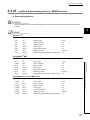
5.1
5.2
5.3
5.4
124
Sample Programs for CC-Link Ver.2 Board . . . . . . . . . . . . . . . . . . . . . . . . . . . . . . . . . . . . . . 124
5.1.1
Description of sample programs . . . . . . . . . . . . . . . . . . . . . . . . . . . . . . . . . . . . . . . . . . . . . 124
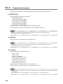
5.1.2
Programming language . . . . . . . . . . . . . . . . . . . . . . . . . . . . . . . . . . . . . . . . . . . . . . . . . . . . 126
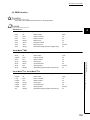
Sample Programs for MELSECNET/H Board. . . . . . . . . . . . . . . . . . . . . . . . . . . . . . . . . . . . . 127
5.2.1
Description of sample programs . . . . . . . . . . . . . . . . . . . . . . . . . . . . . . . . . . . . . . . . . . . . . 127
5.2.2
Programming language . . . . . . . . . . . . . . . . . . . . . . . . . . . . . . . . . . . . . . . . . . . . . . . . . . . . 128
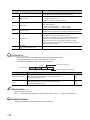
Sample Programs for CC-Link IE Controller Network Board . . . . . . . . . . . . . . . . . . . . . . . . . 129
5.3.1
Description of sample programs . . . . . . . . . . . . . . . . . . . . . . . . . . . . . . . . . . . . . . . . . . . . . 129
5.3.2
Programming language . . . . . . . . . . . . . . . . . . . . . . . . . . . . . . . . . . . . . . . . . . . . . . . . . . . . 130
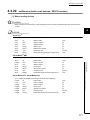
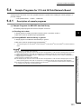
Sample Programs for CC-Link IE Field Network Board . . . . . . . . . . . . . . . . . . . . . . . . . . . . . 131
5.4.1
Description of sample programs . . . . . . . . . . . . . . . . . . . . . . . . . . . . . . . . . . . . . . . . . . . . . 131
5.4.2
Programming language . . . . . . . . . . . . . . . . . . . . . . . . . . . . . . . . . . . . . . . . . . . . . . . . . . . . 132
CHAPTER 6 ERROR CODES
133
7
APPENDIX
141
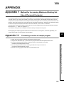
Appendix 1 Method for Increasing Minimum Working Set Size of Personal Computer . . . . . . . . . 141
Appendix 1.1
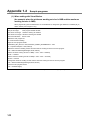
Processing overview of sample program . . . . . . . . . . . . . . . . . . . . . . . . . . 141
Appendix 1.2
Sample programs . . . . . . . . . . . . . . . . . . . . . . . . . . . . . . . . . . . . . . . . . 142
REVISIONS . . . . . . . . . . . . . . . . . . . . . . . . . . . . . . . . . . . . . . . . . . . . . . . . . . . . . . . . . . . . . . . . . . . . . . 144
Warranty . . . . . . . . . . . . . . . . . . . . . . . . . . . . . . . . . . . . . . . . . . . . . . . . . . . . . . . . . . . . . . . . . . . . . . . . 145
8
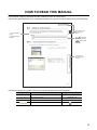
HOW TO READ THIS MANUAL
In this manual, pages are organized and the symbols are used as shown below.
The following page illustration is for explanation purpose only, and the content is different from the actual page.
The chapter of the
current page is
shown.
*shows reference
pages.
$shows reference
manuals.
shows notes
that requires attention.
Remark shows useful
information.
The section of
the current page
is shown.
The following shows the symbols used in this manual with descriptions and examples.
Symbol
[
]
<<
>>
"
"
Description
Menu name on a menu bar
Example
[Project]
Tab name on a screen
<<Existing>> tab
Screen name or item name on a screen
"Option" screen
Button on a screen
button
9
TERMS
This manual uses the following terms unless otherwise specified.
Term
Description
Board
Generic term for PC interface boards supported by MELSEC data link library
Utility
Generic term for utility of PC interface board supported by MELSEC data link library
CC-Link Ver.2 board
MELSECNET/H board
CC-Link IE Controller Network board
CC-Link IE Field Network board
GX Developer
Generic term for Q80BD-J61BT11N and Q81BD-J61BT11 CC-Link system master/local interface
board
Generic term for Q80BD-J71LP21-25,Q81BD-J71LP21-25,Q80BD-J71LP21S-25,
Q80BD-J71LP21G, Q80BD-J71LP21GE, and Q80BD-J71BR11 MELSECNET/H interface board
Generic term for Q80BD-J71GP21-SX, Q80BD-J71GP21S-SX, Q81BD-J71GP21-SX, and
Q81BD-J71GP21S-SX CC-Link IE Controller Network interface board
Generic term for Q80BD-J71GF11-T2 and Q81BD-J71GF11-T2 CC-Link IE Field Network interface
board
Generic product name for SW8D5C-GPPW-E, SW8D5C-GPPW-EA, SW8D5C-GPPW-EV, and
SW8D5C-GPPW-EVA
GX Works2
Generic product name for SWnDNC-GXW2-E and SWnDNC-GXW2-EA (n: version)
MX Component
Generic product name for SWnD5C-ACT-E and SWnD5C-ACT-EA (n: version)
10
CHAPTER 1 OVERVIEW
CHAPTER 1
OVERVIEW
1
This chapter explains overview of the MELSEC data link library.
1.1
MELSEC Data Link Library
MELSEC data link library is a library used to access own station link devices of the board and device memory of other
station's programmable controller CPU which uses the board.
With the MELSEC data link library, programs to access devices or device memories can be created easily without
concern for communication routes.
1.2
Supported Boards
The following table shows the boards supported by the MELSEC data link library.
Board
CC-Link Ver.2 board
MELSECNET/H board
CC-Link IE Controller Network board
CC-Link IE Field Network board
Model Name
Q80BD-J61BT11N, Q81BD-J61BT11
Q80BD-J71LP21-25, Q81BD-J71LP21-25, Q80BD-J71LP21S-25,
Q80BD-J71LP21G, Q80BD-J71LP21GE, Q80BD-J71BR11
Q80BD-J71GP21-SX, Q80BD-J71GP21S-SX,
Q81BD-J71GP21-SX, Q81BD-J71GP21S-SX
Q80BD-J71GF11-T2, Q81BD-J71GF11-T2
1.1 MELSEC Data Link Library
11
CHAPTER 2
PROGRAMMING
This chapter explains how to use the MELSEC data link library.
2.1
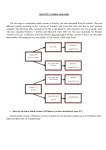
Programming Procedure
The following flow chart shows the procedure to create a user program using the MELSEC data link library on the
personal computer to which the software package is installed.
Programming procedure
Set the development tool to use
the MELSEC data link library.
Page 17, Section 2.3
Create a user program using
the MELSEC data link library.
Open the communication port.
(mdOpen function)
Communicate with the programmable
controller CPU and the board using
functions.
No
End the program?
Yes
Close the port that was opened
by the mdOpen function.
(mdClose function)
Refer to the user's manual
Perform debugging using
the Device monitor utility
A user program is created.
12
of corresponding board.
CHAPTER 2 PROGRAMMING
2.2
2.2.1
Precautions when Using MELSEC Data Link Library
Precautions when programming
2
(1) Multi-thread communications
The MELSEC data link library cannot be accessed from multiple threads within the same process.
Access the MELSEC data link library with a single thread.
(2) Opening and closing of a communication line
Perform the opening and closing processes of a communication line (mdOpen, mdClose) only once at the
beginning and the end of a user program. Repeating opening and closing processes for each communication
causes deterioration of communication performance.
(3) Function execution time at the initial access
The MELSEC data link library obtains detailed information of the programmable controller at the initial access to
the programmable controller CPU. Therefore, a longer function execution time is required for the initial function.
(4) Number of stations for other station accesses
When accessing other stations with the user program, limit the total number of access stations to 256 or less. The
communication performance will be deteriorated if the total number of access stations is 257 or more.
(5) Forcible termination of user program
terminated, the following symptoms may occur.
• The application that is forcibly terminated cannot be ended.
• An error of MELSEC Data Link Library occurs in other application
• The forcible termination affects other Mitsubishi software packages (such as MX Component, GX Works2).
(6) Execution speed
The execution speed and the execution interval of the MELSEC data link library function may be extended
temporarily by Windows® processes or other applications. Create programs considering these conditions.
(7) Static type variables
Do not specify any variables which are declared in static for output arguments of the MELSEC data link library
functions.
(8) Service applications
The MELSEC data link library cannot be accessed from Windows® Service applications.
Access the MELSEC data link library from a user application.
(9) Board reset
When executing the mdBdRst function or mdBdModSet function using a user program, the board rest process of
each function completes at the time when the value is returned.
Create a program which checks the returned value of the function.
13
2.2 Precautions when Using MELSEC Data Link Library
2.2.1 Precautions when programming
When the user program in which the MELSEC data link library operation is currently running is forcibly
(10)64-bit version user program
(a) Accessing CPU modules other than QCPU (Q mode) or RCPU modules
64-bit version user program cannot access CPU modules other than QCPU (Q mode) or RCPU modules. Use
32-bit version user program to access CPU modules other than QCPU (Q mode) or RCPU modules.
(b) Creating 64-bit version user program
To create 64-bit version user program, a project needs to be configured to set the 64-bit platform as a target
platform. For configuring a project and setting a target platform, refer to Help (How to: Configure Projects to
Target Platforms) in Visual Studio®.
(c) Creating 64-bit version user program using Visual Basic®
.NET Framework 4.0 or .NET Framework compatible with .NET Framework 4.0 is required. Use Visual Studio®
2010 or later.
(d) Restriction when creating 64-bit version user programs
64-bit version user programs can be created on a 32-bit version operating system, however, the following
dialog box appears and cannot be executed.
<When using Windows®XP (32-bit version)>
<When using Windows®7 (32-bit version)>
(11)/SAFESEH (Image has Safe Exception Handlers)
Do not use /SAFESEH (Image has Safe Exception Handlers) option. The project cannot be built normally.
(12)Influence of operating system and other applications
When the system resource of the operating system is insufficient due to the automatic start of the update program
of the operating system or other applications, or the devices are accessed from other applications, "Board Driver
I/F error 102 (0066H)" may occur during executing a MELSEC data link library function. Take the following
measures as necessary.
• Retry process of a MELSEC data link library function
• Disable the automatic update of the operating system and other applications
• Stop other applications
(13)Device access when the cyclic data assurance is enabled
Use the batch write/batch read function (mdSendEx/mdSend/mdReceiveEx/mdReceive) to access devices when
enabling the cyclic data assurance (32-bit data integrity assurance and block data assurance per station).
The cyclic data assurance (32-bit data integrity assurance and block data assurance per station) is not enabled while
accessing the device by the random write/random read function (mdRandWEx/mdRandW/mdRandREx/mdRandR).
14
CHAPTER 2 PROGRAMMING
2.2.2
Precautions when accessing own station link devices and other
station's programmable controller devices
It is necessary to establish an interlock depending on a link status between the own station and other station.
2
Data are validated only when the following conditions are satisfied.
(1) MELSECNET/H
(a) Accessing to own station link devices (LX, LY, LB, LW)
Writing/reading data to/from the own station link devices are validated only when the bits of the own station
handshaking status (SB47) and own station data link status (SB49) are OFF (normal communication), and the
bit of the own station module status (SB20) is OFF (normal communication).
However, even if the above conditions are not satisfied, the processing of writing/reading data to/from the
MELSECNET/H board ends normally.
(b) Other station transient access (remote operation and device access of other
station's programmable controller CPU)
While the access is validated for the devices which check the link device accesses, the other station transient
access can be performed when the bits of the handshake status in accessed station (the bits in the accessed
station correspond to SW70 to 73 read from the own station) and OFF (normal communication) and the bits of
the cyclic transmission status (the bits in the accessed station correspond to SW74 to 77 read from the own
station) are OFF (cyclic transmission is being processed).
(2) CC-Link IE Controller Network
Writing/reading data to/from the own station link devices are validated only when the bits of the own station
handshaking status (SB47) and own station data link status (SB49) are OFF (normal communication), and the
bit of the own station module status (SB20) is OFF (normal communication).
However, even if the above conditions are not satisfied, the processing of writing/reading data to/from the CCLink IE Controller Network board ends normally.
(b) Other station transient access (remote operation and device access of other
station's programmable controller CPU)
While the access is validated for the devices which check the link device accesses, the other station transient
access can be performed when the bits of the handshake status in accessed station (the bits in the accessed
station correspond to SWA0 to A7 read from the own station) and the bits of the data link status (the bits in the
accessed station correspond to SWB0 to B7 read from the own station) are OFF (normal communication).
15
2.2 Precautions when Using MELSEC Data Link Library
2.2.2 Precautions when accessing own station link devices and other station's programmable
controller devices
(a) Accessing to own station link devices (LX, LY, LB, LW)
(3) CC-Link IE Field Network
(a) Accessing to own station link devices (RX, RY, RW)
Writing/reading data to/from the own station link devices are validated only when the bits of the own station
handshaking status (SB47) and own station data link status (SB49) are OFF (normal communication).
However, even if the above conditions are not satisfied, the processing of writing/reading data to/from the CCLink IE Field Network board ends normally.
(b) Other station transient access (remote operation and device access of other
station's programmable controller CPU)
While the access is validated for the devices which check the link device accesses, the other station transient
access can be performed when the bits of the handshake status in accessed station (the bits in the accessed
station correspond to SWA0 to A7 read from the own station) and the bits of the data link status (the bits in the
accessed station correspond to SWB0 to B7 read from the own station) are OFF (normal communication).
16
CHAPTER 2 PROGRAMMING
2.3
Settings for Using Functions
This section explains how to set the development tool to use the MELSEC data link library functions.
2
For programming languages supported by boards, refer to the user's manual corresponds to the board.
Page 3 RELATED MANUALS
● To create a 64-bit version user application, a project needs to be configured to set the 64-bit platform as a target platform.
For configuring a project and setting a target platform, refer to Help (How to: Configure Projects to Target Platforms) in
Visual Studio®.
● When creating 64-bit version user programs using Visual Basic®, .NET Framework 4.0 or .NET Framework compatible
with .NET Framework 4.0 is required. Use Visual Studio® 2010 or later as a development environment.
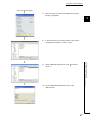
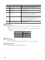
2.3.1
Using Visual Basic®5.0, Visual Basic®6.0
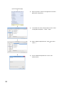
This section explains the setting operation when using Visual Basic®5.0 or Visual Basic®6.0.
Start Visual Basic® and select [Project] - [Add Module].
2)
Select <<Existing>> and select "Mdfunc.bas".
2.3 Settings for Using Functions
2.3.1 Using Visual Basic®5.0, Visual Basic®6.0
1)
"Mdfunc.bas" is stored in the following directory at
installation.
<User-specified folder> - <COMMON> - <INCLUDE>
17
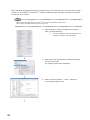
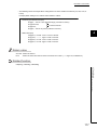
2.3.2
Using Visual C++®5.0, Visual C++®6.0
This section explains the setting operation when using Visual C++®5.0 or Visual C++®6.0.
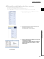
(1) Setting include files
1)
Start Visual C++® and select [Tools] - [Options].
2)
Select <<Directories>> and specify "Include files" for "Show
directories for " .
3)
Double-click the item to be set and browse the folder
containing include files.
"Mdfunc.h" is stored in the following directory at installation.
<User-specified folder> - <COMMON> - <INCLUDE>
4)
18
Add #include<Mdfunc.h> at the beginning of the program.
CHAPTER 2 PROGRAMMING
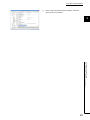
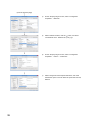
(2) Setting library files
1)
Start Visual C++® and select [Tools] - [Options].
2)
Select <<Directories>> and specify "Library files" for "Show
2
directories for". Browse the folder containing library files as in
(1) on the previous page.
"Mdfunc32.lib" is stored in the following directory at
installation.
<User-specified folder>-<COMMON>-<LIB>
Open the workspace to create a user application and select
[Project] - [Settings].
4)
Select <<Link>> and specify "General" for the category, and
enter "Mdfunc32.lib" in the "Object/library modules" field.
19
2.3 Settings for Using Functions
2.3.2 Using Visual C++®5.0, Visual C++®6.0
3)
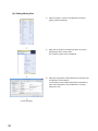
2.3.3
Using Visual Basic®.NET
This section explains the setting operation when using Visual Basic®.NET 2003, or when using Visual Basic® in Visual
Studio® 2005, Visual Studio® 2008, Visual Studio® 2010, Visual Studio® 2012 or Visual Studio® 2013.
Remark
The screens of Visual Studio® 2008 Visual Basic® 2008 are used for the explanation in this section.
These screens are slightly different from other Visual Basic®.
1)
Start Visual Basic®.
For other than Visual Basic®.NET 2003:
Select [Project] - [Add Existing Item].
For Visual Basic®.NET 2003:
Select [File] - [Add Existing Item].
2)
On the "Add Existing Item" screen, select "Mdfunc.vb".
"Mdfunc.vb" is stored in the following directory at installation.
<User-specified folder> - <COMMON> - <INCLUDE>
20
CHAPTER 2 PROGRAMMING
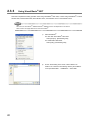
2.3.4
Using Visual C++®.NET 2003, Visual C++®2005,
Visual C++®2008
2
This section explains the setting operation when using Visual C++®.NET 2003, or when using Visual C++® in Visual
Studio® 2005, or Visual Studio® 2008.
Remark
The screens of Visual C++® in Visual Studio® 2008 are used for the explanation in this section.
These screens are slightly different from other Visual C++®.
(1) Setting include files
Start Visual C++® and select [Tools] - [Options].
2)
Select "VC++ Directories" in the folder area of the "Options"
screen.
For other than Visual C++®.NET 2003:
Select "Projects and Solutions" - "VC++ Directories".
For Visual C++®.NET 2003:
Select "Projects" - "VC++ Directories".
Specify "Include Files" for "Show directories for" and click
3)
.
Browse the folder containing include files.
"Mdfunc.h" is stored in the following directory at installation.
<User-specified folder> - <COMMON> - <INCLUDE>
4)
Add #include<Mdfunc.h> at the beginning of the program.
21
2.3 Settings for Using Functions
2.3.4 Using Visual C++®.NET 2003, Visual C++®2005, Visual C++®2008
1)
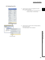
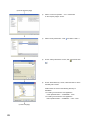
(2) Setting library files
1)
2)
Start Visual C++® and select [Tools] - [Options].
Select "VC++ Directories" in the folder area of the "Options"
screen.
For other than Visual C++®.NET 2003:
Select "Projects and Solutions" - "VC++ Directories".
For Visual C++®.NET 2003:
Select "Projects" - "VC++ Directories".
Specify "Library files" for "Show directories for" , and browse
the folder containing library files as in (1) on the previous
page.
"Mdfunc32.lib" is stored in the following directory at
installation.
For creating a 32-bit version user application
<User-specified folder> - <COMMON> - <LIB>
For creating a 64-bit version user application
<User-specified folder> - <COMMON> - <LIB>- <x64>
3)
Open the project to create a user application and select
[Project] - [project Properties].
4)
Select [Configuration Properties] - [Linker] - "Input" in the
folder area of the "Property Pages" screen.
Enter "MdFunc32.lib" in the "Additional Dependencies" field.
22
CHAPTER 2 PROGRAMMING
2.3.5
Using Visual C++®2010, Visual C++®2012
This section explains the setting operation when using Visual C++® in Visual Studio®2010, or Visual Studio® 2012.
2
Remark
The screens of Visual C++® in Visual Studio® 2010 are used for the explanation in this section.
These screens are slightly different from other Visual C++®.
(1) Setting include files
1)
Open the project to create a user application and select
[View] - [Property Manager]*1.
*1 :
Right-click the user property sheet, and select [Properties]
from the shortcut menu.
The "Property Pages" screen is displayed.
(To the next page)
23
2.3 Settings for Using Functions
2.3.5 Using Visual C++®2010, Visual C++®2012
2)
The menu configuration may differ depending on the
development setting or customized setting.
(From the previous page)
3)
Select "Common Properties" - "VC++ Directories"
on the "Property Pages" screen.
4)
Select "Include Directories". Click the
button and select
"<Edit...>".
5)
On the "Include Directories" screen, click the
then click
6)
button, and
.
On the "Select Directory" screen, select the folder to which
the include file is stored.
"Mdfunc.h" is stored in the following directory at installation.
<User-specified folder> - <COMMON> - <INCLUDE>
7)
24
Add #include<Mdfunc.h> at the beginning of the program.
CHAPTER 2 PROGRAMMING
(2) Setting library files
1)
Open the project to create a user application and select
2
[View] - [Property Manager]*1.
*1 :
2)
The menu configuration may differ depending on the
development setting or customized setting.
Right-click the user property sheet, and select [Properties]
from the shortcut menu.
The "Property Pages" screen is displayed.
2.3 Settings for Using Functions
2.3.5 Using Visual C++®2010, Visual C++®2012
(To the next page)
25
(From the previous page)
3)
Select "Common Properties" - "VC++ Directories"
on the "Property Pages" screen.
4)
Select "Library Directories" . Click
and select "<Edit...>".
5)
On the "Library Directories" screen, click
, and then click
.
6)
On the "Select Directory" screen, select the folder to which
the library file is stored.
"Mdfunc32.lib" is stored in the following directory at
installation.
For creating a 32-bit version user application
<User-specified folder> - <COMMON> - <LIB>
For creating a 64-bit version user application
<User-specified folder> - <COMMON> - <LIB>- <x64>
(To the next page)
26
CHAPTER 2 PROGRAMMING
(From the previous page)
7)
Open the project to create a user application and select
[Project] - [Properties].
2
8)
In the folder area of the "Property Pages" screen, select
"Configuration Properties" - "Linker" - "Input".
Select "Additional Dependencies". Click
2.3 Settings for Using Functions
2.3.5 Using Visual C++®2010, Visual C++®2012
9)
and select
"<Edit...>".
10) On the "Additional Dependencies" screen, enter
"MdFunc32.lib".
27
When /SAFESEH (Image has Safe Exception Handlers) option is set to the linker option, the project cannot be built
normally. For Visual Studio® 2012 Visual C++®, delete the /SAFESEH option following the procedure shown below
because it is set as a default.
Remark
The screens of Visual Studio® 2012 Visual C++® are used for the explanation in this section.
These screens are slightly different from other Visual C++®.
1)
Open the project to create a user application and select
[View] - [Property Manager]*1.
*1 :
2)
The menu configuration may differ depending on the
development setting or customized setting.
Right-click the user property sheet, and select [Properties]
from the shortcut menu.
The "Property Pages" screen is displayed.
3)
Select "Common Properties" - "Linker" - "Advanced"
on the "Property Pages" screen.
28
CHAPTER 2 PROGRAMMING
4)
Select "Image Has Safe Exception Handlers". When the
option has been set, delete it.
2
2.3 Settings for Using Functions
2.3.5 Using Visual C++®2010, Visual C++®2012
29
2.3.6
Using Visual C++®2013
This section explains the setting operation when using Visual C++® in Visual Studio®2013.
Remark
The screens of Visual C++® 2013 opened by converting the sample program "MTEST(VC)" on Windows® 8
Professional (x64) are used for the explanation in this section.
(1) Setting include files
1)
Open the project to create a user application and select
[VIEW] - [Solution Explorer].
2)
Right-click the project in the Solution Explorer, and select
[Properties] from the shortcut menu.
The "Property Pages" screen is displayed.
3)
Select the configuration and the platform to be changed in
the Configuration and the Platform.
In case that there are multiple configurations and platforms,
select "All Configurations" and "All Platforms" to change
settings at a time.
(To the next page)
30
CHAPTER 2 PROGRAMMING
(From the previous page)
4)
On the "Property Pages" screen, select <Configuration
Properties> - <VC++ Directories>.
5)
Select "Include Directories". Click the
2
button and select
"<Edit...>".
6)
On the "Include Directories" screen, click the
then click
On the "Select Directory" screen, select the folder to which
the include file is stored.
"Mdfunc.h" is stored in the following directory at installation.
<User-specified folder> - <COMMON> - <INCLUDE>
8)
Add #include<Mdfunc.h> at the beginning of the program.
31
2.3 Settings for Using Functions
2.3.6 Using Visual C++®2013
7)
button, and
.
(2) Setting library files
1)
Open the project to create a user application and select
[VIEW] - [Solution Explorer].
2)
Right-click the project in the Solution Explorer, and select
[Properties] from the shortcut menu.
The "Property Pages" screen is displayed.
3)
Select the configuration and the platform to be changed in the
Configuration and the Platform.
In case that there are multiple configurations and platforms,
select "All Configurations" and "All Platforms" to change
settings at a time.
(To the next page)
32
CHAPTER 2 PROGRAMMING
(From the previous page)
4)
On the "Property Pages" screen, select <Configuration
2
Properties> - <VC++ Directories>.
5)
Select "Library Directories" . Click
and select "<Edit...>".
6)
On the "Library Directories" screen, click
, and then click
.
On the "Select Directory" screen, select the folder to which
the library file is stored.
"Mdfunc32.lib" is stored in the following directory at
installation.
For creating a 32-bit version user application
<User-specified folder> - <COMMON> - <LIB>
For creating a 64-bit version user application
<User-specified folder> - <COMMON> - <LIB>- <x64>
(To the next page)
33
2.3 Settings for Using Functions
2.3.6 Using Visual C++®2013
7)
(From the previous page)
8)
Open the project to create a user application and select
[PROJECT] - [Properties].
9)
In the folder area of the "Property Pages" screen, select
"Configuration Properties" - "Linker" - "Input".
10) Select "Additional Dependencies". Click
and select
"<Edit...>".
11) On the "Additional Dependencies" screen, enter
"MdFunc32.lib".
34
CHAPTER 2 PROGRAMMING
(3) Setting platform and deleting linker option that are unnecessary
Set the platform by the following operations 1) to 5).
Also, delete unnecessary options by the following operations 6) to 7).
2
When using "Image Has Safe Exception Handlers" option, the project cannot be built normally.
1)
Open the project to create a user application and select
[VIEW] - [Solution Explorer].
2)
Right-click the project in the Solution Explorer, and select
[Properties] from the shortcut menu.
The "Property Pages" screen is displayed.
2.3 Settings for Using Functions
2.3.6 Using Visual C++®2013
3)
Select the configuration and the platform to be changed in the
Configuration and the Platform.
In case that there are multiple configurations and platforms,
select "All Configurations" and "All Platforms" to change
settings at a time.
(To the next page)
35
(From the previous page)
4)
On the "Property Pages" screen, select <Configuration
Properties> - <General>.
5)
Select "Platform Toolset", click the
button, and select
"Visual Studio 2013 - Windows XP (v120_xp)".
6)
On the "Property Pages" screen, select <Configuration
Properties> - <Linker> - <Advanced>.
7)
Select "Image Has Safe Exception Handlers", and check
whether the option is not set. When the option has been set,
delete it.
36
CHAPTER 3 ACCESSIBLE DEVICES AND RANGES
CHAPTER 3
ACCESSIBLE DEVICES AND RANGES
This chapter explains the devices and the ranges that can be accessed when communicating with each type of boards.
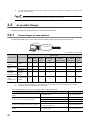
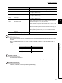
3.1
Access Target
3
The following table shows the accessible other stations.
Model name*1
Item
A series
CPU module
QnA series
CPU module
Q series
A0J2HCPU, A1SCPU, A1SJCPU, A1SHCPU, A1SJHCPU, A1NCPU, A2CCPU,
A2CJCPU, A2NCPU, A2NCPU-S1, A2SCPU, A2SHCPU, A3NCPU, A2ACPU,
A2ACPU-S1, A3ACPU, A2UCPU, A2UCPU-S1, A2USCPU, A2USCPU-S1,
A2USHCPU-S1, A3UCPU, A4UCPU
QCPU(A mode)
Q02CPU-A, Q02HCPU-A, Q06HCPU-A
QnACPU
Q2ACPU, Q2ASCPU, Q2ASHCPU, Q2ACPU-S1,
Q2ASCPU-S1, Q2ASHCPU-S1, Q3ACPU, Q4ACPU, Q4ARCPU
CPU module
QCPU(Q mode)
CPU module
LCPU
Head module
iQ-R series
CPU module
• Basic model QCPU
Q00JCPU, Q00CPU, Q01CPU
• High Performance model QCPU
Q02CPU, Q02HCPU, Q06HCPU, Q12HCPU, Q25HCPU
• Process CPU
Q02PHCPU, Q06PHCPU, Q12PHCPU, Q25PHCPU
• Redundant CPU
Q12PRHCPU, Q25PRHCPU
• Universal model QCPU
Q03UDVCPU, Q03UDECPU, Q04UDHCPU, Q04UDEHCPU, Q04UDVCPU,
Q06UDHCPU, Q06UDEHCPU, Q06UDVCPU, Q10UDHCPU, Q10UDEHCPU,
Q13UDHCPU, Q13UDEHCPU, Q13UDVCPU, Q20UDHCPU, Q20UDEHCPU,
Q26UDHCPU, Q26UDEHCPU, Q26UDVCPU, Q50UDEHCPU, Q100UDEHCPU
L02SCPU, L02SCPU-P, L02CPU, L02CPU-P, L06CPU, L06CPU-P, L26CPU,
L26CPU-P, L26CPU-BT, L26CPU-PBT
LJ72GF15-T2
RCPU
R04CPU, R08CPU, R16CPU, R32CPU, R120CPU
Ethernet adapter module
NZ2GF-ETB
Intelligent device station
AJ65BT-R2
(a slave station on the CC-Link system that can perform the transient transmission)
CC-Link IE Field remote device station
PC interface
board
*1 :
• Input module
NZ2GF2B1-16D, NZ2GFCE3-16D, NZ2GFCE3-16DE, NZ2GFCM1-16D, NZ2GFCM116DE
• Output module
NZ2GF2B1-16T, NZ2GF2B1-16TE, NZ2GFCE3-16T, NZ2GFCE3-16TE, NZ2GFCM116T, NZ2GFCM1-16TE
• Analog input module/Analog output module
NZ2GF2B-60AD4, NZ2GF2B-60DA4
• Temperature control module
NZ2GF2B-60TCTT4, NZ2GF2B-60TCRT4
• High-speed counter module
NZ2GFCF-D62PD2
CC-Link Ver.2 board
Q80BD-J61BT11N, Q81BD-J61BT11
MELSECNET/H board
Q80BD-J71LP21-25, Q81BD-J71LP21-25, Q80BD-J71LP21S-25,
Q80BD-J71LP21G, Q80BD-J71LP21GE, Q80BD-J71BR11
CC-Link IE Controller Network
board
Q80BD-J71GP21-SX, Q80BD-J71GP21S-SX, Q81BD-J71GP21-SX,
Q81BD-J71GP21S-SX
CC-Link IE Field Network board
Q80BD-J71GF11-T2, Q81BD-J71GF11-T2
Cannot be accessed when using a product whose model name or version is not supported by the network.
For the supported network of each product, refer to the manual of product.
37
3.1 Access Target
L series
ACPU*2
*2 :
For CC-Link IE Field network, only A2UCPU, A2UCPU-S1, A2USCPU, A2USCPU-S1, A2USHCPU-S1, A3UCPU, and
A4UCPU can be accessed.
When accessing other than QCPU (Q mode) or RCPU, use 32-bit version user application.
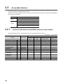
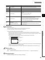
3.2
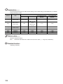
Accessible Ranges
This section explains accessible ranges when communicating with boards.
3.2.1
Access target on own network
The following module, board, or own station can be accessed on the network connected to each board.
Own station
Own network
Access target
: Accessible : Not accessible
Access target*1
Own station
CC-Link Ver.2
Own network
RCPU
LCPU,
Ethernet
QCPU (Q mode),
ACPU,
CC-Link IE
Intelligen
Head
adapter
PC interface
QnACPU,
Field remote
t device
module
module
board
QCPU (A mode)
devicestation
station
*3
CC-Link
MELSECNET/H
MELSECNET/H
board
MELSECNET/10
CC-Link IE
CC-Link IE
Controller
Controller
Network board
Network
*3
board *2
CC-Link IE
CC-Link IE Field
Field
Network board
*1 :
*2 :
*3 :
Network
For details of access target, refer to Page 37, Section 3.1 Access Target.
When the own station number is 64, other station cannot be accessed. Only the own station can be accessed.
Only 32-bit version user application can be accessed.
For the accessible devices of each access target, refer to the following table.
Access target
Access to link devices or buffer memory of own
station
PC interface board
Page 40, Section 3.3.1
QnACPU, QCPU (Q mode), LCPU, RCPU
Page 41, Section 3.3.2
ACPU, QCPU (A mode)
Page 42, Section 3.3.3
Ethernet adapter module, Head module
Page 43, Section 3.3.4
Access to other station buffer memory of CC-Link
CC-Link network module,
CC-Link Ver.2 board, etc.
Page 43, Section 3.3.5
Access using the SEND function or the RECV
function
QnACPU, QCPU (Q mode), LCPU, RCPU,
PC interface board
Page 44, Section 3.3.6
Access to devices of other station module
38
Reference
CHAPTER 3 ACCESSIBLE DEVICES AND RANGES
3.2.2
Access target when connected via network
The following shows the accessibility when accessing via multiple networks.
Own station
Own network
Relay station Access target network Access target
3
The combination other than shown in the following table cannot be accessed.
Accessing the access target via multiple networks is not supported by CC-Link network.
: Accessible : Not accessible
Access target*1
Own network
Relay
Access target
station
network
Network
Network
CC-Link IE Field
RCPU
Network
CC-Link IE Controller
CC-Link IE Field
Network
Network
CC-Link IE Field
Network
MELSECNET/10
MELSECNET/10
QCPU
CC-Link IE Controller
(Q mode)
Network, CC-Link IE
*2
CC-Link IE Field
Field Network
CC-Link IE Field
Network
CC-Link IE Controller
Network
Network
LCPU
CC-Link IE Field
Network
ACPU*3,
Head module,
(Q mode),
QnACPU,
Ethernet adapter
PC interface
QCPU
module
board
(A mode)
Field
remote
device
station
QnACPU
MELSECNET/10
ACPU
QCPU
MELSECNET/10
(A mode)
*1 :
*2 :
*3 :
For details of access target, refer to Page 37, Section 3.1 Access Target.
When using a CPU module whose number of mountable network module is one, the CPU module cannot be set as a
relay station.
For CC-Link IE Field network, A2UCPU, A2UCPU-S1, A2USCPU, A2USCPU-S1, A2USHCPU-S1, A3UCPU, and
A4UCPU can be accessed.
For the accessible devices of each access target, refer to the following table.
Access target
Access to devices of other station module
Reference
QnACPU, QCPU (Q mode), LCPU, RCPU
Page 41, Section 3.3.2
ACPU, QCPU (Amode)
Page 42, Section 3.3.3
Ethernet adapter module, Head module
Page 43, Section 3.3.4
Access using the SEND function or the RECV
QnACPU, QCPU (Q mode), LCPU, RCPU,
function
PC interface board
Page 44, Section 3.3.6
39
3.2 Accessible Ranges
3.2.2 Access target when connected via network
MELSECNET/H,
QCPU
RCPU
CC-Link IE Controller
CC-Link IE Controller
CC-Link IE
LCPU,
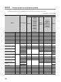
3.3
Accessible Devices
This section explains accessible devices for boards.
The table in this section divides the functions used for access into "Batch" and "Random" and indicates accessibility for
each of these two categories.
Access type
Batch
Description
Batch write (mdSend, mdSendEx)
Batch read (mdReceive, mdReceiveEx)
Random write (mdRandW, mdRandWEx)
Random
Random read (mdRandR, mdRandREx)
Bit set (mdDevSet, mdDevSetEx)
Bit reset (mdDevRst, mdDevRstEx)
3.3.1
Access to link devices and buffer memory of own station
The following table shows the accessible devices when accessing a board (own station).
: Accessible : Not accessible
Access target
Device
Access type
CC-Link Ver.2
MELSECNET/H
CC-Link IE Controller
CC-Link IE Field
board
board
Network board
Network board
Link input
LX
Batch/Random
Link output
LY
Batch/Random
Link relay
LB
Batch/Random
Link register
LW
Batch/Random
Link special relay
SB
Batch/Random
Link special register
SW
Batch/Random
Remote input
RX
Batch/Random
Remote output
RY
Batch/Random
RWw
Batch/Random
RWr
Batch/Random
Buffer memory
—
Batch/Random
Random access buffer
—
Batch/Random
Remote register
(for transmission)
Remote register
(for reception)
40
CHAPTER 3 ACCESSIBLE DEVICES AND RANGES
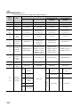
3.3.2
Access to devices of QnA, Q, L, and R series module
The following table shows the accessible devices of QnACPU, QCPU (Q mode), LCPU, and RCPU on other station.
: Accessible : Not accessible
Access target*1
Device
Access type
QnACPU,
QCPU, LCPU
3
RCPU
Input
X
Batch/Random
Output
Y
Batch/Random
Latch relay
L
Batch/Random
Internal relay
M
Batch/Random
Special relay
SM
Batch/Random
Data register
D
Batch/Random
SD
Batch/Random
Annunciator
F
Batch/Random
Timer (contact, coil, current value)
T
Batch/Random
Long timer (contact, coil, current value)
LT
Batch/Random
*2
Counter (contact, coil, current value)
C
Batch/Random
Long counter (contact, coil, current value)
LC
Batch/Random
*2
Index register
Z
Batch/Random
Long index register
LZ
Batch/Random
*2
Unit refresh register
RD
Batch/Random
*2
File register
R, ZR
Batch/Random
*3
Extended file register
ER
Batch/Random
*3
Link relay
B
Batch/Random
Link register
W
Batch/Random
Link special relay
SB
Batch/Random
Link special register
SW
Batch/Random
Retentive timer (contact, coil, current value)
ST
Batch/Random
Long retentive timer (contact, coil, current value)
LST
Batch/Random
*2
Edge relay
V
Batch/Random
Batch/Random
Batch/Random
3.3 Accessible Devices
3.3.2 Access to devices of QnA, Q, L, and R series module
Special register
Link direct device
(link input,
Jn\X
link output,
Jn\Y
link relay,
Jn\B
link register,
Jn\W
link special relay,
Jn\SB
link special register)
Jn\SW
Intelligent function module device
Un\G
*1 :
*2 :
*3 :
For details of access target, refer to Page 37, Section 3.1 Access Target.
Cannot be accessed from MELSECNET/H board.
Cannot be accessed with Q00JCPU.
41
3.3.3
Access to devices of A series module
The following table shows the accessible devices of ACPU or QCPU (A mode) on other station.
: Accessible : Not accessible
Access target
A0J2HCPU,
A1SCPU,
A1SJCPU,
Device
Access type
A1SHCPU,
A2UCPU,
A1SJHCPU,
A2UCPU-S1,
A2CCPU,
A1NCPU*1
A2CJCPU,
A2NCPU,
A3NCPU,
A3ACPU*1
A2USCPU,
A2USCPU-S1,
A4UCPU
A2USHCPU-S1,
A2NCPU-S1,
A3UCPU
A2SCPU,
QCPU (A mode)
A2SHCPU,
A2ACPU,
A2ACPU-S1*1
Input
X
Batch/Random
Output
Y
Batch/Random
Latch relay
L
Batch/Random
Internal relay
M
Batch/Random
Special relay
M9000 to
Batch/Random
Data register
D
Batch/Random
Special register
D9000 to
Batch/Random
Annunciator
F
Batch/Random
Batch/Random
Batch
Random
Batch
Random
Timer (contact, coil,
current value)
Timer
(setting value main)
T
Timer
(setting value sub1)
Batch
Timer
(setting value sub2, sub3)
Random
Counter (contact, coil,
current value)
Counter
(setting value main)
C
Counter
(setting value sub1)
Batch
Random
Batch
Batch
(setting value sub2, sub3)
Batch/Random
Random
Counter
Random
Accumulator
A
Batch/Random
Index register
Z, V
Batch/Random
File register
R
Batch/Random
Extended file register
ER
Batch/Random
Link relay
B
Batch/Random
Link register
W
Batch/Random
*1 :
42
Cannot be accessed from CC-Link IE Field Network board.
CHAPTER 3 ACCESSIBLE DEVICES AND RANGES
3.3.4
Access to Ethernet adapter module, Head module, and CC-Link
IE Field remote device station
The following table shows the accessible Ethernet adapter module, Head module, and CC-Link IE Field remote device
station via CC-Link and CC-Link IE Field Network.
: Accessible : Not accessible
3
Access target
Device
Access type
CC-Link IE Field
Ethernet adapter
Head module
module
remote device
station
Input
X
Batch/Random
Output
Y
Batch/Random
Special relay
SM
Batch/Random
Special register
SD
Batch/Random
Link register
W
Batch/Random
Link special relay
SB
Batch/Random
Link special register
SW
Batch/Random
Intelligent function module
device
Buffer memory
Un\G
Batch/Random
*1
Intelligent function module
access device
*1 :
3.3 Accessible Devices
3.3.4 Access to Ethernet adapter module, Head module, and CC-Link IE Field remote device station
3.3.5
When accessing via CC-Link IE Field Network, the buffer memory can be accessed only by the mdRemBufWriteEx
function or the mdRemBufReadEx function.
Access to other station buffer memory of CC-Link
The following table shows the accessible buffer memory of CC-Link network module and CC-LinkVer.2 board.
The multiple CPU system (when the logical station is specified) cannot be accessed.
: Accessible : Not accessible
Device
Link special relay
Access type
Accessibility
SB
Batch
Link special register
SW
Batch
Remote input
RX
Batch
Remote output
RY
Batch
Remote register
RW
Batch
Buffer memory
—
Batch
Random access buffer
—
Batch
When the own station number is 64, other station cannot be accessed. Only the own station can be accessed.
43
3.3.6
Access using the SEND function or the RECV function
The same operation as device access, the SEND function and the RECV function execute Batch write (mdSend,
mdSendEx) or Batch read (mdReceive, mdReceiveEx) with specified device type for each function.
: Accessible : Not accessible
Access target
Device
Access type
CPU module
(QnA/Q/L/R)
RECV function
SEND function(with arrival acknowledgment)
SEND function(without arrival acknowledgment)
PC interface board
Batch
—
(Own station)
Batch
● The SEND function and the RECV function are not supported by CC-Link.
● The SEND function and the RECV function are supported by SW1DNC-MNETG-B Version 1.08J or later.
● The SEND function and the RECV function are not supported by the following modules:
• A series CPU module
• Ethernet adapter module
• Head module
44
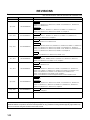
CHAPTER 4 FUNCTIONS
CHAPTER 4
FUNCTIONS
This chapter explains the MELSEC data link library functions.
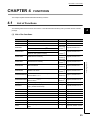
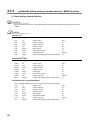
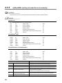
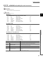
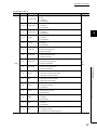
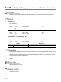
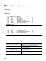
4.1
List of Functions
The following table shows the list of the functions in the MELSEC data link library that is provided with the software
4
package.
(1) List of the functions
Function name
Description
Remarks
Reference
mdOpen
Opens a communication line.
—
Page 56, Section 4.3.1
mdClose
Closes a communication line.
—
Page 57, Section 4.3.2
mdSendEx
mdReceiveEx
Batch writes devices.
Sends data. (SEND
function)*1*2
(Extended
Receives data. (RECV function)*1*2
function*3)
mdRandREx
Reads devices randomly.
mdDevSetEx
Sets a bit device.
mdDevRstEx
Resets a bit device.
mdTypeRead
mdControl
(Extended
function*3)
(Extended
function*3)
(Extended
function*3)
(Extended
function*3)
Writes data to the buffer memory of a remote
(Extended
device station.*4 *5 *6
function*3)
Reads data from the buffer memory of a remote
(Extended
device station.*4 *5 *6
function*3)
Reads the type of programmable controller CPU.
Remote operation of programmable controller
CPU. (RUN/STOP/PAUSE).
Page 58, Section 4.3.3
Page 62, Section 4.3.4
Page 66, Section 4.3.5
Page 69, Section 4.3.6
Page 73, Section 4.3.7
Page 75, Section 4.3.8
Page 77, Section 4.3.9
Page 79, Section 4.3.10
—
Page 81, Section 4.3.11
—
Page 86, Section 4.3.12
mdWaitBdEvent
Waits for an event occurrence.
—
Page 87, Section 4.3.13
mdBdRst
Resets the board.
—
Page 90, Section 4.3.14
mdBdModSet
Sets the mode of the board.
—
Page 91, Section 4.3.15
mdBdModRead
Reads the mode of the board.
—
Page 93, Section 4.3.16
mdBdLedRead
Reads the LED information of the board.
—
Page 95, Section 4.3.17
mdBdSwRead
Reads the switch status of the board.
—
Page 101, Section 4.3.18
mdBdVerRead
Reads the version information of the board.
—
Page 103, Section 4.3.19
—
Page 106, Section 4.3.20
mdInit
Initializes programmable controller information
table
45
4.1 List of Functions
Writes devices randomly.
mdRemBufReadEx
function*3)
Batch reads devices.
mdRandWEx
mdRemBufWriteEx
(Extended
*1 :
*2 :
*3 :
*4 :
*5 :
*6 :
Applicable to CC-Link IE Controller Network boards and CC-Link IE Field Network boards.
Supported by the 1.08J or later version of CC-Link IE Controller Network board.
A function in which the access range is extended according to the extension of the device points at the access target. It
is accessible to all device numbers.
Use extended functions when creating a new program.
Applicable to CC-Link IE Field Network boards.
The functions can be used for CC-Link IE Field Network board with a serial number whose first five digits are '15102' or
higher, and SW1DNC-CCIEF-B Ver. 1.06G or later.
Applicable only for 32-bit version user application.
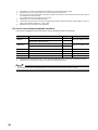
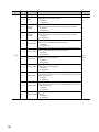
(2) List of conventional compatible functions
Conventional compatible functions are functions used for programs created conventionally.
Function name
mdSend
mdReceive
Description
Batch writes devices.
Sends data. (SEND
—
function)*1*2
Batch reads devices.
Receives data. (RECV
Remarks
—
—
function)*1*2
—
Reference
Page 107, Section 4.3.21
Page 111, Section 4.3.22
mdRandW
Writes devices randomly.
—
Page 115, Section 4.3.23
mdRandR
Reads devices randomly.
—
Page 118, Section 4.3.24
mdDevSet
Sets a bit device.
—
Page 122, Section 4.3.25
mdDevRst
Resets a bit device.
—
Page 123, Section 4.3.26
*1 :
*2 :
Applicable to MELSECNET/H boards, CC-Link IE Controller Network boards, and CC-Link IE Field Network boards.
Supported by the 1.08J or later version of CC-Link IE Controller Network board.
When using the conventional compatible functions, the accessible device numbers are from 0 to 32767.
46
CHAPTER 4 FUNCTIONS
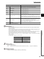
4.2
Common Specifications of Functions
This section explains the definitions of arguments commonly used with the MELSEC data link library functions.
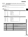
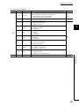
4.2.1
Specifying channel number
The following table shows the channels used with the MELSEC data link library.
Channel
number
Channel name
51
MELSECNET/H (1 slot)
52
MELSECNET/H (2 slot)
MELSECNET/H board
53
MELSECNET/H (3 slot)
Channel number is set with MELSECNET/H utility.
54
MELSECNET/H (4 slot)
81
CC-Link (1 slot)
CC-Link Ver.2 board
82
CC-Link (2 slot)
Channel number is set with the channel number setting switch.
83
CC-Link (3 slot)
84
CC-Link (4 slot)
151
152
153
181
182
183
184
The channels are set as follows according to the SW1 and
SW2 settings:
81: Off, Off; 82: On, Off; 83: Off, On; 84: On, On
CC-Link IE Controller Network
(Channel No. 151)
CC-Link IE Controller Network
(Channel No. 152)
CC-Link IE Controller Network
CC-Link IE Controller Network board
Channel number is set with CC IE Control utility.
(Channel No. 153)
CC-Link IE Controller Network
4.2 Common Specifications of Functions
4.2.1 Specifying channel number
154
4
Description
(Channel No. 154)
CC-Link IE Field Network
(Channel No. 181)
CC-Link IE Field Network
(Channel No. 182)
CC-Link IE Field Network
CC-Link IE Field Network board
Channel number is set with CC IE Field utility.
(Channel No. 183)
CC-Link IE Field Network
(Channel No. 184)
47
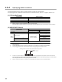
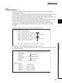
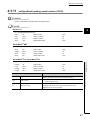
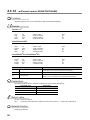
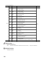
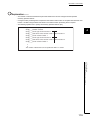
4.2.2
Specifying station numbers
The following tables show the station numbers specified in the MELSEC data link library.
For specifying network numbers and station numbers for extended functions, refer toPage 50, Section 4.2.3.
(1) CC-Link Ver.2 board
Specification
Station number
Own station
255(FFH)
Other station
0(00H) to 63(3FH)*1
The logical station number set with the utility
65(41H) to 239(EFH)
*1 :
Station number 64 cannot be specified on the CC-Link Ver.2 board
Also, when the own station number is 64, other station cannot be specified. (Only the own station can be accessed.)
(2) MELSECNET/H board
Station number
Specification
Upper byte
Lower byte
255(FFH)
Own station
0(00H)*4
Station number
*3
Other
Network number
station
1(01H) to 239(EFH)
Group number 1 to 32*1 *2
1(01H) to 120(78H)*5
125(7DH)*4
129(81H) to 160(A0H)
All stations*1
240(F0H)
65(41H) to 239(EFH)
The logical station number set with the utility
*1 :
*2 :
*3 :
All stations and group numbers can be specified when using the SEND function (mdSend) without arrival
acknowledgment.
For MELSECNET/10 mode, only group numbers from 1 to 9 (129(81H) to 137(89H)) can be specified.
For specifying another station, set a network number in the upper byte of the station number.
<Setting a station number when another station is specified>
Network number
Station number
Upper
*4 :
*5 :
48
Lower
Access to the control station or master station (station number 0) specified with the network number on the network.
When accessing the control station (operating as a control station) and the mater station (operating as a master station
when using the submaster function), specify the station number.
Station numbers from 65(41H) to 120(78H) can be specified when using CC-Link IE Controller Network.
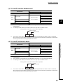
CHAPTER 4 FUNCTIONS
(3) CC-Link IE Controller Network board
Station number
Specification
Upper byte
Lower byte
255(FFH)
Own station
0(00H)*3
1(01H) to 120(78H)
Station number
Other
Network number*2
station
1(01H) to 239(EFH)
Group Number 1 to 32*1
125(7DH)*3
129(81H) to 160(A0H)
All stations*1
0(00H) to 239(EFH)
The logical station number set with the utility
*1 :
*2 :
4
240(F0H)
All stations and group numbers can be specified when using the SEND function (mdSend) without arrival
acknowledgment.
For specifying another station, set a network number in the upper byte of the station number.
<Setting a station number when another station is specified>
Network number
Station number
Upper
*3 :
Lower
Access to the control station or master station (station number 0) specified with the network number on the network.
When accessing the control station (operating as a control station) and the mater station (operating as a master station
when using the submaster function), specify the station number.
(4) CC-Link IE Field Network board
Upper byte
Own station
Lower byte
255(FFH)
0(00H)*4 to 120(78H)
Station number
Other
station
Group Number 1 to 32*1 *2
All stations
Network number.*3
125(7DH)*4
1(01H) to 239(EFH)
129(81H) to 160(A0H)
*1
240(F0H)
0(00H) to 239(EFH)
The logical station number set with the utility
*1 :
*2 :
*3 :
4.2 Common Specifications of Functions
4.2.2 Specifying station numbers
Station number
Specification
All stations and group numbers can be specified when using the SEND function (mdSend) without arrival
acknowledgment.
Group numbers can be specified when using MELSECNET/H network or CC-Link IE Controller Network.
For specifying another station, set a network number in the upper byte of the station number.
<Setting a station number when another station is specified>
Network number
Station number
Upper
*4 :
Lower
Access to the control station or master station (station number 0) specified with the network number on the network.
When accessing the control station (operating as a control station) and the mater station (operating as a master station
when using the submaster function), specify the station number.
49
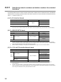
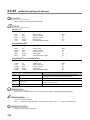
4.2.3
Specifying network numbers and station numbers for extended
functions
The following tables show the network numbers and the station numbers used for extended functions in the MELSEC
data link library. For specifying network numbers and station numbers for functions other than the extended functions,
refer to Page 48, Section 4.2.2.
(1) For CC-Link Ver.2 board
Specification
Network numbers
0(00H)
Other station
The logical station number set with the utility
*1 :
Station number
255(FFH)
Own station
0(00H) to 63(3FH)*1
65(41H) to 239(EFH)
Station number 64 cannot be specified on the CC-Link Ver.2 board.
Also, when the own station number is 64, other station cannot be specified. (Only the own station can be accessed.)
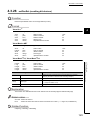
(2) For MELSECNET/H board
Specification
Own station
Network numbers
Station number
0(00H)
255(FFH)
0(00H)*1
Other
station
Station number
1(01H) to 239(EFH)
1(01H) to 120(78H)*2
125(7DH)*1
The logical station number set with the utility
*1 :
*2 :
0(00H)
65(41H) to 239(EFH)
Access to the control station or master station (station number 0) specified with the network number on the network.
When accessing the control station (operating as a control station) and the mater station (operating as a master station
when using the submaster function), specify the station number.
Station numbers from 65(41H) to 120(78H) can be specified when using CC-Link IE Controller Network.
(3) For CC-Link IE Controller Network board
Specification
Own station
Network numbers
Station number
0(00H)
255(FFH)
0(00H)*2
Station number
Other
1(01H) to 239(EFH)
station
129(81H) to160(A0H)
*1
240(F0H)
The logical station number set with the utility
*2 :
50
125(7DH)*2
Group Number 1 to 32*1
All stations
*1 :
1(01H) to120(78H)
0(00H)
0(00H) to 239(EFH)
All stations and group numbers can be specified when using the SEND function (mdSendEx) without arrival
acknowledgment.
Access to the control station or master station (station number 0) specified with the network number on the network.
When accessing the control station (operating as a control station) and the mater station (operating as a master station
when using the submaster function), specify the station number.
CHAPTER 4 FUNCTIONS
(4) For CC-Link IE Field Network board
Specification
Own station
Network numbers
Station number
0(00H)
255(FFH)
0(00H)*3 to120(78H)
Station number
Other
station
Group Number 1 to 32*1 *2
1(01H) to 239(EFH)
*1
*1 :
*2 :
*3 :
129(81H) to160(A0H)
240(F0H)
All stations
The logical station number set with the utility
125(7DH)*3
0(00H)
0(00H) to 239(EFH)
All stations and group numbers can be specified when using the SEND function (mdSendEx) without arrival
acknowledgment.
Group numbers can be specified when using MELSECNET/H network or CC-Link IE Controller Network.
Access to the control station or master station (station number 0) specified with the network number on the network.
When accessing the control station (operating as a control station) and the mater station (operating as a master station
when using the submaster function), specify the station number.
4
4.2 Common Specifications of Functions
4.2.3 Specifying network numbers and station numbers for extended functions
51
4.2.4
Specifying device types
Device types specified in the MELSEC data link library can be either a code number or a device name.
(1) Link devices and buffer memory of own station
Device type
Device
Code specification
Device name
Decimal
Hexadecimal
specification
1
0001H
DevX
2
0002H
DevY
Link input
LX
Remote input
RX
Link output
LY
Remote output
RY
Link special relay
SB
5
0005H
DevSM
Link special register
Sw
14
000EH
DevSD
Link relay
LB
23
0017H
DevB
Link register
LW
24
0018H
DevW
Remote register (for transmission)
RWw
36
0024H
DevWw
Remote register (for reception)
RWr
37
0025H
DevWr
Buffer memory
—
50
0032H
DevSPB
Random access buffer
—
33
0021H
DevMRB
(2) Devices of other station module
Device type
Device
Code specification
Decimal
52
Device name
Hexadecimal
specification
Input
X
1
0001H
DevX
Output
Y
2
0002H
DevY
Latch relay
L
3
0003H
DevL
Internal relay
M
4
0004H
DevM
Special relay
SM
5
0005H
DevSM
Annunciator
F
6
0006H
DevF
Timer contact
T
7
0007H
DevTT
Timer coil
T
8
0008H
DevTC
Counter contact
C
9
0009H
DevCT
Counter coil
C
10
000AH
DevCC
Timer current value
T
11
000BH
DevTN
Counter current value
C
12
000CH
DevCN
Data register
D
13
000DH
DevD
Special register
SD
14
000EH
DevSD
Timer setting value main
T
15
000FH
DevTM
Timer setting value sub1
T
16
0010H
DevTS
Timer setting value sub2
T
16002
3E82H
DevTS2
Timer setting value sub3
T
16003
3E83H
DevTS3
Counter setting value main
C
17
0011H
DevCM
Counter setting value sub1
C
18
0012H
DevCS
CHAPTER 4 FUNCTIONS
Device type
Device
Code specification
Device name
Decimal
Hexadecimal
specification
Counter setting value sub2
C
18002
4652H
DevCS2
Counter setting value sub3
C
18003
4653H
DevCS3
Accumulator
A
19
0013H
DevA
Index register
File register *1
Extended file register
*1 *2
Z
20
0014H
DevZ
V
21
0015H
DevV
R
22
0016H
DevR
ZR
220
00DCH
DevZR
ER
22000 to 22256
55F0H to 56F0H
DevER0 to 256
Link relay
B
23
0017H
DevB
Link register
W
24
0018H
DevW
Link special relay
SB
25
0019H
DevQSB
Retentive timer contact
ST
26
001AH
DevSTT
Retentive timer coil
ST
27
001BH
DevSTC
Link special register
SW
28
001CH
DevQSW
Edge relay
V
30
001EH
DevQV
ST
35
0023H
DevSTN
LZ
38
0026H
DevLZ
Unit refresh register
RD
39
0027H
DevRD
Long Timer contact
LT
41
0029H
DevLTT
Long Timer coil
LT
42
002AH
DevLTC
Long Timer current value
LT
43
002BH
DevLTN
Long counter contact
LC
44
002CH
DevLCT
Long counter coil
LC
45
002DH
DevLCC
Long counter current value
LC
46
002EH
DevLCN
Long retentive timer contact
LST
47
002FH
DevSTT
Long retentive timer coil
LST
48
0030H
DevSTC
Long retentive timer current value
LST
49
0031H
DevSTN
Jn\X
1001 to 1255
03E9H to 04E7H
DevLX1 to 255
Jn\Y
2001 to 2255
07D1H to 08CFH
DevLY1 to 255
Jn\B
23001 to 23255
59D9H to 5AD7H
DevLB1 to 255
Jn\W
24001 to 24255
5DC1 to 5EBFH
DevLW1 to 255
Link direct device link special relay*1 *3
Jn\SB
25001 to 25255
61A9H to 62A7H
DevLSB1 to 255
Link direct device link special register*1 *3
Jn\SW
28001 to 28255
6D61H to 6E5FH
DevLSW1 to 255
Un\G
29000 to 29255
7148H to 7247H
DevSPG0 to 255
Link direct device link input
*1 *3
Link direct device link output*1 *3
Link direct device link relay
*1 *3
Link direct device link register
*1 *3
Intelligent function module device
Buffer memory
Intelligent function module access device
*1 *4
*1 :
*2 :
*3 :
*4 :
With the random read function (mdRandR, mdRandREx), execute normally even specifying devices that do not exist.
With the random read function (mdRandR, mdRandREx), the function may complete normally if the specified devices do
not exist. (The read data is error.)
Specify a block number (0 to 256) for the lower 3 digits of the code specification (decimal) and the numerical value of the
device specification.
Specify a network number (1 to 255) for the lower 3 digits of the code specification (decimal) and the numerical value of
the device specification.
Specify a value (start I/O number divided by 16) for the lower 3 digits of the code specification (decimal) and the
numerical value of the device specification.
53
4.2 Common Specifications of Functions
4.2.4 Specifying device types
Retentive timer current value
Long index register
4
(3) Buffer memory of CC-Link other station
When accessing the buffer memory of CC-Link network module or other CC-Link Ver.2 board from CC-Link Ver.2
board, specify the following device type.
Device type
Device
Code specification
Device name
Decimal
Hexadecimal
specification
Buffer memory*1
-32768
8000H
DevRBM
Random access buffer*1
-32736
8020H
DevRAB
Remote input*1
-32735
8021H
DevRX
Remote output*1
-32734
8022H
DevRY
-32732
8024H
DevRW
-32669
8063H
DevSB
-32668
8064H
DevSW
Remote
register*1
Link special
relay*1
Link special register*1
*1 :
These devices can not be used for random write (mdRandW, mdRandWEx), random read (mdRandR, mdRandREx), bit
set (mdDevSet, mdDevSetEx) and bit reset (mdDevRst, mdDevRstEx).
(4) The SEND function and the RECV function
The same operation as device access, the SEND function and the RECV function execute Batch write (mdSend,
mdSendEx) or Batch read (mdReceive, mdReceiveEx) with specified device type for each function.
Device type
Device
RECV function
SEND function (with arrival acknowledgment)
SEND function (without arrival acknowledgment)
54
Code specification
Device name
Decimal
Hexadecimal
specification
101
0065H
DevMAIL
102
0066H
DevMAILNC
CHAPTER 4 FUNCTIONS
4.3
Function Details
The following shows the detailed specifications of the MELSEC data link library.
This section provides the description of the instructions in the layout as shown below.
4
#
$
%
&
4.3 Function Details
'
(
Indicates an description of the function.
Indicates the description format in each programming language.
Item
Description
A format for Microsoft ® Visual C++®
Visual C++®
A format for the following Visual Basic®
• Visual Basic®.NET 2003
• Visual Studio® 2005 Visual Basic®
Visual Basic®.NET
• Visual Studio® 2008 Visual Basic®
• Visual Studio® 2010 Visual Basic®
• Visual Studio® 2012 Visual Basic®
• Visual Studio® 2013 Visual Basic®
A format for the following Visual Basic®
Visual
Basic®5.0,
Visual
Basic®6.0
• Visual Basic® 5.0
• Visual Basic® 6.0
Describes arguments of the function.
Describes features of the function and details of arguments.
Indicates the return values.
Indicates related functions for programming.
55
4.3.1
mdOpen (opening communication lines)
Function
Open a communication line by specifying a channel number of communication line.
Format
Visual C++®
ret = mdOpen(chan,mode,path);
short
short
short
long
ret;
chan;
mode;
*path;
//Return value
//Channel number of communication line
//Dummy
//Opened line path pointer
OUT
IN
IN
OUT
Visual Basic®.NET
ret = mdOpen(chan,mode,path)
Short
Short
Short
Integer
ret
chan
mode
path
;Return value
;Channel number of communication line
;Dummy
;Opened line path pointer
OUT
IN
IN
OUT
Visual Basic®5.0, Visual Basic®6.0
ret% = mdOpen(chan%,mode%,path&)
Integer
Integer
Integer
Long
ret
chan
mode
path
;Return value
;Channel number of communication line
;Dummy
;Opened line path pointer
Argument
chan
Channel number of communication line
OUT
IN
IN
OUT
Description
Specify the channel number of communication line.
(Page 47, Section 4.2.1)
mode
Dummy
Specify -1.
path
Opened line path pointer
Return the opened line path.
Explanation
• A path of the channel used for argument of another function is returned to the opened line path pointer.
• When using multiple communication lines, opening for each channel number is necessary.
Return value
Success : Return the value 0.
Error
: Return the value other than 0. Refer to the list of error codes. ( Page 133, CHAPTER 6)
Related function
mdClose()
56
CHAPTER 4 FUNCTIONS
4.3.2
mdClose (closing communication lines)
Function
Close a communication line by specifying a communication line path.
Format
Visual C++®
4
ret = mdClose(path);
short
ret;
//Return value
OUT
long
path;
//Path of channel
IN
Visual Basic®.NET
ret = mdClose(path)
Short
ret
;Return value
OUT
Integer
path
;Path of channel
IN
Visual Basic®5.0, Visual Basic®6.0
ret% = mdClose(path&)
Integer
ret
;Return value
OUT
Long
path
;Path of channel
IN
path
Path of channel
Description
4.3 Function Details
4.3.2 mdClose (closing communication lines)
Argument
Specify the path of channel whose communication line is opened.
(Use the path which is returned when executing mdOpen.)
Explanation
When using multiple communication lines, they need to be closed for each channel number.
Return value
Success : Return the value 0.
Error
: Return the value other than 0. Refer to the list of error codes. ( Page 133, CHAPTER 6)
Related function
mdOpen()
57
4.3.3
mdSendEx (batch writing extended devices / SEND function)
(1) Batch writing extended devices
Function
Batch write data to the devices on the target station for the number of written data bytes from the start device
number.
Format
Visual C++®
ret = mdSendEx(path,netno,stno,devtyp,devno,size,data);
long
ret;
//Return value
OUT
long
path;
//Path of channel
IN
long
netno;
//Network number
IN
long
stno;
//Station number
IN
long
devtyp;
//Device type
IN
long
devno;
//Start device number
IN
long
*size;
//Written byte size
IN/OUT
short
data[ ];
//Written data (single-precision integer array)
IN
Visual Basic®.NET
ret = mdSendEx(path,netno,stno,devtyp,devno,size,data(0))
Integer
ret
;Return value
OUT
Integer
path
;Path of channel
IN
Integer
netno
;Network number
IN
Integer
stno
;Station number
IN
Integer
devtyp
;Device type
IN
Integer
devno
;Start device number
IN
Integer
size
;Written byte size
IN/OUT
Short
data(n)
;Written data (single-precision integer array)
IN
Visual Basic®5.0, Visual Basic®6.0
ret% = mdSendEx(path&,netno%,stno%,devtyp%,devno%,size%,data%(0))
Long
58
ret
;Return value
OUT
Long
path
;Path of channel
IN
Long
netno
;Network number
IN
Long
stno
;Station number
IN
Long
devtyp
;Device type
IN
Long
devno
;Start device number
IN
Long
size
;Written byte size
IN/OUT
Any
data(n)
;Written data (single-precision integer array)
IN
CHAPTER 4 FUNCTIONS
Argument
path
Path of channel
netno
Network number
stno
Station number
devtyp
Device type
Description
Specify the path of channel whose communication line is opened.
(Use the path which is returned when executing mdOpen.)
Specify the network number of target station.
( Page 50, Section 4.2.3)
Specify the station number of target station.
( Page 50, Section 4.2.3)
Specify the type of device to which the data is written.
( Page 52, Section 4.2.4)
Specify the start device number of device to which the data is written.
• Specify the start device number with a multiple of 8 for the access to a
devno
Start device number
bit device (except for LTT, LTC, LSTT, and LSTC).
4
• Specify the start device number with a multiple of 16 (0, 16, 32...) for the
access to a bit device (RX, RY, SB) of CC-Link other station link device.
Specify the byte size to be written in even number.
• When the specified byte size to be written exceeds the device range
size
Written byte size
(-5: size error), the applicable size is returned to "size".
• When a double word device (LZ, LTN, LCN, or LSTN) is specified to
"devtyp", specify the size in multiples of 4.
Written data
data
(single-precision integer array)
Specify the data to be written in single-precision integer array.
Explanation
• When the specified written byte size exceeds the transient transmission size, data are divided inside the
function and written.
• When accessing another station, the extended comment information will be deleted by writing data to the
(extended file register) which overlaps with the setting areas of the sub2 and sub3 programs.
• When a double word device (LZ, LTN, LCN, or LSTN) is specified to "devtyp", store the data to be written to
"data" as follows:
Example) When "devtyp" is LZ and "size" is 8
Array
Value
data(0)
Lower 1 word of LZ0
data(1)
Upper 1 word of LZ0
data(2)
Lower 1 word of LZ1
data(3)
Upper 1 word of LZ1
Return value
Success : Return the value 0.
Error
: Return the value other than 0. Refer to the list of error codes. ( Page 133, CHAPTER 6)
Related function
mdOpen(), mdClose(), mdSend(), mdReceive(), mdReceiveEx()
59
4.3 Function Details
4.3.3 mdSendEx (batch writing extended devices / SEND function)
block (extended file register) to which the extended comment is assigned.
• When accessing another station, the sub2 and sub3 programs will be deleted by writing data to the block
(2) SEND function
Function
Send data to the specified channel number of the target station.
Format
Visual C++®
ret = mdSendEx(path,netno,stno,devtyp,devno,size,data);
long
ret;
//Return value
OUT
long
path;
//Path of channel
IN
long
netno;
//Network number
IN
long
stno;
//Station number
IN
long
devtyp;
//Device type
IN
long
devno;
//Channel number
IN
long
*size;
//Send byte size
IN/OUT
short
data[ ];
//Send data (single-precision integer array)
IN
Visual Basic®.NET
ret = mdSendEx(path,netno,stno,devtyp,devno,size,data(0))
Integer
ret
;Return value
OUT
Integer
path
;Path of channel
IN
Integer
netno
;Network number
IN
Integer
stno
;Station number
IN
Integer
devtyp
;Device type
IN
Integer
devno
;Channel number
IN
Integer
size
;Send byte size
IN/OUT
Short
data(n)
;Send data (single-precision integer array)
IN
Visual Basic®5.0, Visual Basic®6.0
ret% = mdSendEx(path&, netno%,stno%,devtyp%,devno%,size%,data%(0))
60
Long
ret
;Return value
OUT
Long
path
;Path of channel
IN
Long
netno
;Network number
IN
Long
stno
;Station number
IN
Long
devtyp
;Device type
IN
Long
devno
;Channel number
IN
Long
size
;Send byte size
IN/OUT
Any
data(n)
;Send data (single-precision integer array)
IN
CHAPTER 4 FUNCTIONS
Argument
Description
Specify the path of channel whose communication line is opened.
path
Path of channel
netno
Network number
stno
Station number
(Use the path which is returned when executing mdOpen.)
Specify the network number of target station.
( Page 50, Section 4.2.3)
Specify the station number of target station.
( Page 50, Section 4.2.3)
Logical station numbers cannot be specified.
Specify whether to send data with arrival acknowledgment or without
devtyp
arrival acknowledgment.
Device type
• With arrival acknowledgment*1 : Specify 101(65H)
4
• Without arrival acknowledgment: Specify 102(66H)
devno
Specify a channel used by the own station and a target station channel.
Channel number
For details of specifying the channels, refer to Explanation shown below.
Specify the byte size of send data in even number.
size
• Specify the byte size within the range of 2 to 1920.
Send byte size
• When accessing via MELSECNET/10 network, specify the byte size
within the range of 2 to 960.
Send data
data
Specify the data to be written in single-precision integer array.
(single-precision integer array)
*1 :
Do not specify all stations or group numbers for the station number when sending data with arrival acknowledgment.
Explanation
• This function supports the SEND instruction of the link dedicated instruction.
For details of the functions , refer to the manuals of each board.
• The following explains how to specify the channel numbers.
4.3 Function Details
4.3.3 mdSendEx (batch writing extended devices / SEND function)
Target station channel
4 bytes
Channel number
3
2
1
Item
0
Channel used by the own station
Description
Specify a target station channel.
target station channel
channel used by the
own station
• MELSECNET/H board, CC-Link IE Controller Network board
1 to 8
• CC-Link IE Field Network board
1 to 2
Specify a channel used by the own station.
• CC-Link IE Controller Network board
1 to 8
• CC-Link IE Field Network board
1 to 2
Return value
Success : Return the value 0.
Error
: Return the value other than 0. Refer to the list of error codes. ( Page 133, CHAPTER 6)
Related function
mdOpen(), mdClose(), mdSend(), mdReceive(), mdReceiveEx()
61
4.3.4
mdReceiveEx (batch reading extended devices / RECV
function)
(1) Batch reading extended devices
Function
Batch read data from the devices on the target station for the number of read data bytes from the start device
number.
Format
Visual C++®
ret = mdReceiveEx(path,netno,stno,devtyp,devno,size,data);
long
ret;
//Return value
OUT
long
path;
//Path of channel
IN
long
netno;
//Network number
IN
long
stno;
//Station number
IN
long
devtyp;
//Device type
IN
long
devno;
//Start device number
IN
long
*size;
//Read byte size
IN/OUT
short
data[ ];
//Read data (single-precision integer array)
OUT
Visual Basic®.NET
ret = mdReceiveEx(path,netno,stno,devtyp,devno,size,data(0))
Integer
ret
;Return value
OUT
Integer
path
;Path of channel
IN
Integer
netno
;Network number
IN
Integer
stno
;Station number
IN
Integer
devtyp
;Device type
IN
Integer
devno
;Start device number
IN
Integer
size
;Read byte size
IN/OUT
Short
data(n)
;Read data (single-precision integer array)
OUT
Visual Basic®5.0, Visual Basic®6.0
ret% =mdReceiveEx(path&,netno%,stno%,devtyp%,devno%,size%,data%(0))
62
Long
ret
;Return value
OUT
Long
path
;Path of channel
IN
Long
netno
;Network number
IN
Long
stno
;Station number
IN
Long
devtyp
;Device type
IN
Long
devno
;Start device number
IN
Long
size
;Read byte size
IN/OUT
Any
data(n)
;Read data (single-precision integer array)
OUT
CHAPTER 4 FUNCTIONS
Argument
path
Path of channel
netno
Network number
stno
Station number
devtyp
Device type
Description
Specify the path of channel whose communication line is opened.
(Use the path which is returned when executing mdOpen.)
Specify the station number of target station.
( Page 50, Section 4.2.3)
Specify the station number of target station.
( Page 50, Section 4.2.3)
Specify the type of device from which the data is read.
( Page 52, Section 4.2.4)
Specify the start device number of device range to be read.
• Specify the start device number with a multiple of 8 for the access to a
devno
Start device number
bit device (except for LTT, LTC, LSTT, and LSTC).
4
• Specify the start device number with a multiple of 16 (0, 16, 32...) for the
access to a bit device (RX, RY, SB) of CC-Link other station link device.
Specify the byte size to be read in even number.
• When the specified byte size to be read exceeds the device range (-5:
size
Read byte size
size error), the applicable size is returned to "size".
• When a double word device (LZ, LTN, LCN, or LSTN) is specified to
"devtyp", specify the size in multiples of 4.
Read data
data
(single-precision integer array)
Store the data being read.
Explanation
When the specified read byte size exceeds the transient transmission size, data are divided inside the function
and read.
When a double word device (LZ, LTN, LCN, or LSTN) is specified to "devtyp", the data is stored to "data" as
4.3 Function Details
4.3.4 mdReceiveEx (batch reading extended devices / RECV function)
follows:
Example) When "devtyp" is LZ and "size" is 8
Array
Value
data(0)
Lower 1 word of LZ0
data(1)
Upper 1 word of LZ0
data(2)
Lower 1 word of LZ1
data(3)
Upper 1 word of LZ1
Return value
Success : Return the value 0.
Error
: Return the value other than 0. Refer to the list of error codes. ( Page 133, CHAPTER 6)
Related function
mdOpen(), mdClose(), mdReceive(), mdSend(), mdSendEx()
63
(2) RECV function
Function
Read data of the specified channel number from the data which are received by the own station.
Format
Visual C++®
ret = mdReceiveEx(path,netno,stno,devtyp,devno,size,data);
long
ret;
//Return value
OUT
long
path;
//Path of channel
IN
long
netno;
//Network number
IN
long
stno;
//Station number
IN
long
devtyp;
//Device type
IN
long
devno;
//Channel number
IN
long
*size;
//Receive byte size
IN/OUT
short
data[ ];
//Receive data (single-precision integer array)
OUT
Visual Basic®.NET
ret = mdReceiveEx(path,netno,stno,devtyp,devno,size,data(0))
Integer
ret
;Return value
OUT
Integer
path
;Path of channel
IN
Integer
netno
;Network number
IN
Integer
stno
;Station number
IN
Integer
devtyp
;Device type
IN
Integer
devno
;Channel number
IN
Integer
size
;Receive byte size
IN/OUT
Short
data(n)
;Receive data(single-precision integer array)
OUT
Visual Basic®5.0, Visual Basic®6.0
ret% = mdReceiveEx(path&, netno%,stno%,devtyp%,devno%,size%,data%(0))
Long
64
ret
;Return value
OUT
Long
path
;Path of channel
IN
Long
netno
;Network number
IN
Long
stno
;Station number
IN
Long
devtyp
;Device type
IN
Long
devno
;Channel number
IN
Long
size
;Receive byte size
IN/OUT
Any
data(n)
;Receive data(single-precision integer array)
OUT
CHAPTER 4 FUNCTIONS
Argument
Description
path
Path of channel
Specify the path of channel whose communication line is opened.
(Use the path which is returned when executing mdOpen.)
netno
Network number
Specify 0(0H).
stno
Station number
Specify the own station (255(FFH)).
devtyp
Device type
Specify the RECV function(101(65H)).
Channel number
Specify the own station channel number on which the received messages
are stored.
• CC-Link IE Controller Network board
1 to 8
• CC-Link IE Field Network board
1 to 2
devno
size
4
Specify the byte size of received data in even number.
• Specify the byte size within the range of 2 to 1920.
• When receiving the data which are transmitted by MELSECNET/H
Receive byte size
board with CC-Link IE Controller Network board or CC-Link IE
Controller Network board, specify within the range of 2 to 960.
The size of received actual data is received.
Receive data
data
with send source information
(single-precision integer array)
Received actual data and send source information are stored as singleprecision integer array.
Reserve an area for the specified receive byte size and send source
information (6 bytes).
Explanation
This function supports the RECV instruction of the link dedicated instruction.
For details of the function, refer to the manuals of each board.
• Receive byte size and send source information (6 bytes) are stored in “receive data with send source
information (data)”. Reserve an area for [receive byte size and send source information (6 bytes)] in “receive
data with send source information (data)”.
• Data are stored in “receive data with send source information (data)” as shown below.
Receive data with send source information (data)
data[0] Send source network number
data[1] Send source station number Send source information
(6 bytes)
data[2] Send source channel number
data[3]
Actual data
Receive byte size
(size)
• Only the actual data with the specified receive byte size (size) is stored when the received actual data size is
greater than the specified receive byte size (size).
• 125(7DH) is stored to the send source station number when the station number of the send source is 0.
Return value
Success : Return the value 0.
Error
: Return the value other than 0. Refer to the list of error codes. ( Page 133, CHAPTER 6)
Related function
mdOpen(), mdClose(), mdReceive(), mdSend(), mdSendEx()
65
4.3 Function Details
4.3.4 mdReceiveEx (batch reading extended devices / RECV function)
< Receive data with send source information (data) >
4.3.5
mdRandWEx (writing extended devices randomly)
Function
Write data to the devices on the target station specified with the randomly-specified devices.
Format
Visual C++®
ret = mdRandWEx(path,netno,stno,dev,buf,bufsize);
long
long
long
long
long
short
long
ret;
path;
netno;
stno;
dev[ ];
buf[ ];
bufsize;
//Return value
//Path of channel
//Network number
//Station number
//Randomly-specified device
//Written data (single-precision integer array)
//Dummy
OUT
IN
IN
IN
IN
IN
IN
Visual Basic®.NET
ret = mdRandWEx(path,netno,stno,dev(0),buf(0),bufsize)
Integer
Integer
Integer
Integer
Integer
Short
Integer
ret
path
netno
stno
dev(n)
buf(n)
bufsize
;Return value
;Path of channel
;Network number
;Station number
;Randomly-specified device
;Written data (single-precision integer array)
;Dummy
OUT
IN
IN
IN
IN
IN
IN
Visual Basic®5.0, Visual Basic®6.0
ret% = mdRandWEx(path&,netno%,stno%,dev%(0),buf%(0),bufsize%)
Long
Long
Long
Long
Long
Any
Long
ret
path
netno
stno
dev(n)
buf(n)
bufsize
;Return value
;Path of channel
;Network number
;Station number
;Randomly-specified device
;Written data (single-precision integer array)
;Dummy
Argument
path
Path of channel
OUT
IN
IN
IN
IN
IN
IN
Description
Specify the path of channel whose communication line is opened.
(Use the path which is returned when executing mdOpen.)
netno
Network number
Specify the network number of target station.( Page 50, Section 4.2.3)
stno
Station number
Specify the station number of target station.( Page 50, Section 4.2.3)
dev
Randomly-specified device
Specify the number of blocks, the device type, the start device number,
and points of device to be written.
For details, refer to Explanation shown on the next page.
buf
bufsize
66
Written data
(single-precision integer array)
Dummy
Specify the data to be written to the array variable of buf[0] or later.
—
CHAPTER 4 FUNCTIONS
Explanation
• The number of transient transmissions performed inside of the function changes with the specified
randomly-specified devices.
• A longer function processing time is required for the random write function as compared with the batch write
function. Consider using the batch write function if a shorter function processing time is required.
• When accessing another station, the extended comment information will be deleted by writing data to the
block (extended file register) to which the extended comment is assigned.
• When accessing another station, the sub2 and sub3 programs will be deleted by writing data to the block
(extended file register) which overlaps with the setting areas of the sub2 and sub3 programs.
4
• If an error occurs when writing devices randomly to B or W of the own station in MELSECNET(II) or
MELSECNET/10, blocks with errors may exist among blocks in which the write function is normally
completed.
• The following explains how to specify the randomly-specified devices (dev).
Randomly-specified devices (dev)
dev[0]
Number of blocks
dev[1]
Device type of block number 1
dev[2]
Start device number of block number 1
dev[3]
Points of block number 1
dev[4]
Device type of block number 2
dev[5]
Start device number of block number 2
dev[6]
Points of block number 2
Block number 1
Block number 2
• The following shows an example when writing data to multiple devices.
Example) When all bits of M100 to M115 are set to OFF, and 10, 200, 300, and 400 are written to D10, D11,
D12, and D13 respectively.
Randomly-specified devices (dev)
dev[0]=2;
dev[1]=DevM;
dev[2]=100;
dev[3]=16;
dev[4]=DevD;
dev[5]=10;
dev[6]=4;
Two specified ranges (M100 to M115, D10 to D13)
M100 and later
16 points (M100 to M115)
D10 and later
4 points (D10 to D13)
Written data (buf)
buf[0]=0;
All bits are OFF.
buf[1]=10;
Stores 10 to D10.
buf[2]=200;
Stores 11 to D200.
buf[3]=300;
Stores 12 to D300.
buf[4]=400;
Stores 13 to D400.
67
4.3 Function Details
4.3.5 mdRandWEx (writing extended devices randomly)
The number of blocks that can be specified is within 1 to 32767.
• The following shows an example when writing data to one of the double word devices (LZ, LTN, LCN, or
LSTN).
Example) When writing 0x1 to LCN100 and 0x10000 to LCN101
Randomly-specified devices (dev)
dev[0]=1;
dev[1]=DevLCN;
dev[2]=100;
dev[3]=2;
One specified range (LCN100 to LCN101)
LCN100 and later
2 points (LCN100 to LCN101)
Written data (buf)
buf[0]=0x1;
Lower 1 word of LCN100.
buf[1]=0x0;
Upper 1 word of LCN100.
buf[2]=0x0;
Lower 1 word of LCN101.
buf[3]=0x1;
Upper 1 word of LCN101.
Return value
Success : Return the value 0.
Error
: Return the value other than 0. Refer to the list of error codes. ( Page 133, CHAPTER 6)
Related function
mdOpen(), mdClose(), mdRandREx()
68
CHAPTER 4 FUNCTIONS
4.3.6
mdRandREx (reading extended devices randomly)
Function
Read the device specified with the randomly-specified devices from the target station.
Format
Visual C++®
4
ret = mdRandREx(path,netno,stno,dev,buf,bufsize);
long
ret;
//Return value
OUT
long
path;
//Path of channel
IN
long
netno;
//Network number
IN
long
stno;
//Station number
IN
long
dev[ ];
//Randomly-specified device
IN
short
buf[ ];
//Read data (single-precision integer array)
OUT
long
bufsize;
//Number of bytes of read data
IN
Visual Basic®.NET
ret = mdRandREx(path,netno,stno,dev(0),buf(0),bufsize)
Integer
ret
;Return value
OUT
Integer
path
;Path of channel
IN
netno
;Network number
IN
Integer
dev(n)
;Randomly-specified device
IN
Integer
dev(n)
;Randomly selected device
IN
Short
buf(n)
;Read data (single-precision integer array)
OUT
Integer
bufsize
;Number of bytes of read data
IN
4.3 Function Details
4.3.6 mdRandREx (reading extended devices randomly)
Integer
Visual Basic®5.0, Visual Basic®6.0
ret% = mdRandREx(path&,netno%,stno%,dev%(0),buf%(0),bufsize%)
Long
ret
;Return value
OUT
Long
path
;Path of channel
IN
Long
netno
;Network number
IN
Long
stno
;Station number
IN
Long
dev(n)
;Randomly-specified device
IN
Any
buf(n)
;Read data (single-precision integer array)
OUT
Long
bufsize
;Number of bytes of read data
IN
69
Argument
path
Path of channel
netno
Network number
Description
Specify the path of channel whose communication line is opened.
(Use the path which is returned when executing mdOpen.)
Specify the network number of target station.
( Page 50, Section 4.2.3)
Specify the station number of target station.
stno
Station number
dev
Randomly-specified device
( Page 50, Section 4.2.3)
Specify the number of blocks, the device type, the start device number,
and points of device to be read.
For details, refer to Explanation shown on the next page.
buf
Store the read data to the array variable of buf[0] or later.
Read data
(single-precision integer array)
For details of checking the read data, refer to Explanation shown on the
next page.
Specify the number of bytes of read data.
bufsize
Number of bytes of read data
For details of values to be specified, refer to Explanation shown on the
next page.
Explanation
• The number of transient transmissions performed inside of the function changes with the specified randomly
selected devices.
• A longer function processing time is required for the random read function as compared with the batch read
function. Consider using the batch read function if a shorter function processing time is required.
• The following explains how to specify the randomly-specified devices (dev).
Randomly-specified devices (dev)
dev[0]
Number of blocks
dev[1]
Device type of block number 1
dev[2]
Start device number of block number 1
dev[3]
Points of block number 1
dev[4]
Device type of block number 2
dev[5]
Start device number of block number 2
dev[6]
Points of block number 2
Block number 1
Block number 2
The number of blocks that can be specified is within 1 to 32767.
70
CHAPTER 4 FUNCTIONS
• The following shows an example when reading multiple devices.
Example) When reading the values of M100 to M115, D10 to D13, M0 to M13, and the current value of T10.
M100 to M115
All bits are OFF.
D10 to D13
10 for D10, 200 for D11, 300 for D12, and 400 for D13
M0 to M13
All bits are ON.
Current value of T10 10 (1 second) for the current value of T10
Note that the above values are presumed values in the current status of the target devices.
Randomly-specified devices (dev)
dev[0]=4;
Four specified ranges
(M100 to M115, D10 to D13, M0 to M13, T10)
dev[1]=DevM;
dev[2]=100;
dev[3]=16;
16 points (M100 to M115)
dev[4]=DevD;
D10 and later
dev[5]=10;
dev[6]=4;
4 points (D10 to D13)
dev[7]=DevM;
M0 and later
dev[8]=0;
dev[9]=14;
4
M100 and later
14 points (M0 to M13)
dev[10]=DevTN;
Current and later values of T10 timer
dev[11]=10;
dev[12]=1;
1 point (T10)
Number of bytes of read data (bufsize)
Specify the number of bytes of array variable buf[ ] which stores the read data.
4.3 Function Details
4.3.6 mdRandREx (reading extended devices randomly)
(buf[0] to buf[6] = 7) x 2 = 14 bytes
Enter "14" for this example.
Read data (buf)
buf[0]=0;
All bits of M100 to M115 are OFF
(16 points of bit information can be stored.)
buf[1]=10;
Current value of D10
buf[2]=200;
Current value of D11
buf[3]=300;
Current value of D12
buf[4]=400;
Current value of D13
buf[5]=0x3fff;
All bits of M0 to M13 are ON
buf[6]=10;
Current value of T10 is 10 (1 second).
71
• The following shows an example when reading data from one of the double word devices (LZ, LTN, LCN, or
LSTN).
Example) When reading current values of LCN100 and LCN101
(LCN100 is 0x1 and LCN101 is 0x10000)
Randomly-specified devices (dev)
dev[0]=1;
dev[1]=DevLCN;
dev[2]=100;
dev[3]=2;
One specified range (LCN100 to LCN101)
LCN100 and later
2 points (LCN100 to LCN101)
Number of bytes of read data (bufsize)
Specify the number of bytes of array variable buf[ ] which stores the read data.
(buf[1] to buf[4] = 4) x 2 = 8 bytes
Enter "8" for this example.
Read data (buf)
buf[0]=0x1;
Lower 1 word of LCN100.
buf[1]=0x0;
Upper 1 word of LCN100.
buf[2]=0x0;
Lower 1 word of LCN101.
buf[3]=0x1;
Upper 1 word of LCN101.
Return value
Success : Return the value 0.
Error
: Return the value other than 0. Refer to the list of error codes. ( Page 133, CHAPTER 6)
Related function
mdOpen(), mdClose(), mdRandWEx()
72
CHAPTER 4 FUNCTIONS
4.3.7
mdDevSetEx (setting extended bit devices)
Function
Set the specified bit device on the target station (to ON).
Format
Visual C++®
4
ret = mdDevSetEx(path,netno,stno,devtyp,devno);
long
ret;
//Return value
OUT
long
path;
//Path of channel
IN
long
netno;
//Network number
IN
long
stno;
//Station number
IN
long
devtyp;
//Device type
IN
long
devno;
//Specified device number
IN
Visual Basic®.NET
ret = mdDevSetEx(path,netno,stno,devtyp,devno)
Integer
ret
;Return value
OUT
Integer
path
;Path of channel
IN
Integer
netno
;Network number
IN
stno
;Station number
IN
Integer
devtyp
;Device type
IN
Integer
devno
;Specified device number
IN
4.3 Function Details
4.3.7 mdDevSetEx (setting extended bit devices)
Integer
Visual Basic®5.0, Visual Basic®6.0
ret% = mdDevSetEx(path&,netno%,stno%,devtyp%,devno%)
Long
ret
;Return value
OUT
Long
path
;Path of channel
IN
Long
netno
;Network number
IN
Long
stno
;Station number
IN
Long
devtyp
;Device type
IN
Long
devno
;Specified device number
IN
Argument
path
Path of channel
netno
Network number
stno
Station number
devtyp
Device type
devno
Specified device number
Description
Specify the path of channel whose communication line is opened.
(Use the path which is returned when executing mdOpen.)
Specify the network number of target station.
( Page 50, Section 4.2.3)
Specify the station number of target station.
( Page 50, Section 4.2.3)
Specify the type of device to be set (ON).
(Page 52, Section 4.2.4)
Specify the device number of device to be set (ON).
73
Explanation
This function is a dedicated function for bit devices such as link relays (B) and internal relays (M).
Return value
Success : Return the value 0.
Error
: Return the value other than 0. Refer to the list of error codes. ( Page 133, CHAPTER 6)
Related function
mdOpen(), mdClose(), mdDevRstEx()
74
CHAPTER 4 FUNCTIONS
4.3.8
mdDevRstEx (resetting extended bit devices)
Function
Reset the specified bit device on the target station (to OFF).
Format
Visual C++®
4
ret = mdDevRstEx(path,netno,stno,devtyp,devno);
long
ret;
//Return value
OUT
long
path;
//Path of channel
IN
long
netno;
//Network number
IN
long
stno;
//Station number
IN
long
devtyp;
//Device type
IN
long
devno;
//Specified device number
IN
Visual Basic®.NET
ret = mdDevRstEx(path,netno,stno,devtyp,devno)
Integer
ret
;Return value
OUT
Integer
path
;Path of channel
IN
Integer
netno
;Network number
IN
stno
;Station number
IN
Integer
devtyp
;Device type
IN
Integer
devno
;Specified device number
IN
4.3 Function Details
4.3.8 mdDevRstEx (resetting extended bit devices)
Integer
Visual Basic®5.0, Visual Basic®6.0
ret% = mdDevRstEx(path&,netno%,stno%,devtyp%,devno%)
Long
ret
;Return value
OUT
Long
path
;Path of channel
IN
Long
netno
;Network number
IN
Long
stno
;Station number
IN
Long
devtyp
;Device type
IN
Long
devno
;Specified device number
IN
Argument
path
Path of channel
netno
Network number
stno
Station number
devtyp
Device type
devno
Specified device number
Description
Specify the path of channel whose communication line is opened.
(Use the path which is returned when executing mdOpen.)
Specify the network number of target station.
( Page 50, Section 4.2.3)
Specify the station number of target station.
( Page 50, Section 4.2.3)
Specify the type of device to be reset (OFF).
(Page 52, Section 4.2.4)
Specify the device number of device to be reset (OFF).
75
Explanation
This function is a dedicated function for bit devices such as link relays (B) and internal relays (M).
Return value
Success : Return the value 0.
Error
: Return the value other than 0. Refer to the list of error codes. ( Page 133, CHAPTER 6)
Related function
mdOpen(), mdClose(), mdDevSetEx()
76
CHAPTER 4 FUNCTIONS
4.3.9
mdRemBufWriteEx (writing data to buffer memory of remote
device station)
Function
Write data to the buffer memory of a target station (remote device station of CC-Link IE Field Network).
Format
4
Visual C++®
ret = mdRemBufWriteEx (path,netno,stno,offset,size,data);
long
ret;
//Return value
OUT
long
path;
//Path of channel
IN
long
netno;
//Network number
IN
long
stno;
//Station number
IN
long
offset;
//Offset
IN
long
*size;
//Written byte size
IN
short
data[];
//Written data (single-precision integer array)
IN
Visual Basic®.NET
ret = mdRemBufWriteEx (path,netno,stno,offset,size,data(0))
ret
;Return value
OUT
Integer
path
;Path of channel
IN
Integer
netno
;Network number
IN
Integer
stno
;Station number
IN
Integer
offset
;Offset
IN
Integer
size
;Written byte size
IN
Short
data(n)
;Written data (single-precision integer array)
IN
Argument
path
Path of channel
netno
Network number
stno
Station number
offset
Offset
size
Written byte size
data
Written data (single-precision integer
array)
Description
Specify the path of channel whose communication line is opened.
(Use the path which is returned when executing mdOpen.)
Specify the network number of target station.
( Page 50, Section 4.2.3)
Specify the station number of target station.
( Page 50, Section 4.2.3)
Specify the start address of the remote device station buffer memory to be
written.
Specify the byte size to be written in even number (2 to 480).
Specify the data to be written in single-precision integer array.
77
4.3 Function Details
4.3.9 mdRemBufWriteEx (writing data to buffer memory of remote device station)
Integer
Explanation
• This function writes data only to the buffer memory of the remote device station on a CC-Link IE Field
Network.
Data cannot be written to the buffer memory of an intelligent function module controlled by a CC-Link IE
Field Network Head module.
When writing data to an intelligent function module controlled by a CC-Link IE Field Network Head module,
use mdSendEx/mdSend function.
• Be sure that the write byte size from offset does not exceed the buffer memory range of the remote device
station. Failure to do so may cause a timeout error.
For the buffer memory range of a remote device station, refer to the manuals of each remote device station.
• This function is applicable only for 32-bit version user application.
Return value
Success: Return the value 0.
Error: Return the value other than 0. Refer to the list of error codes. ( Page 133, CHAPTER 6)
Related function
mdOpen(), mdClose(), mdRemBufReadEx()
78
CHAPTER 4 FUNCTIONS
4.3.10
mdRemBufReadEx (reading data from buffer memory of remote
device station)
Function
Read data from the buffer memory of a target station (remote device station of CC-Link IE Field Network).
Format
4
Visual C++®
ret = mdRemBufReadEx (path,netno,stno,offset,size,data);
long
ret;
//Return value
OUT
long
path;
//Path of channel
IN
long
netno;
//Network number
IN
long
stno;
//Station number
IN
long
offset;
//Offset
IN
long
*size;
//Read byte size
IN
short
data[];
//Read data (single-precision integer array)
OUT
Visual Basic®.NET
ret = mdRemBufReadEx (path,netno,stno,offset,size,data(0))
ret
;Return value
OUT
Integer
path
;Path of channel
IN
Integer
netno
;Network number
IN
Integer
stno
;Station number
IN
Integer
offset
;Offset
IN
Integer
size
;Read byte size
IN
Short
data(n)
;Read data (single-precision integer array)
OUT
Argument
path
Path of channel
netno
Network number
stno
Station number
offset
Offset
size
Read byte size
data
Read data (single-precision integer
array)
Description
Specify the path of channel whose communication line is opened.
(Use the path which is returned when executing mdOpen.)
Specify the network number of target station.
( Page 50, Section 4.2.3)
Specify the station number of target station.
( Page 50, Section 4.2.3)
Specify the start address of the remote device station buffer memory to be
read.
Specify the byte size to be read in even number (2 to 480).
Specify the data to be read in single-precision integer array.
79
4.3 Function Details
4.3.10 mdRemBufReadEx (reading data from buffer memory of remote device station)
Integer
Explanation
• This function reads data only from the buffer memory of the remote device station on a CC-Link IE Field
Network.
Data cannot be read from the buffer memory of an intelligent function module controlled by a CC-Link IE
Field Network Head module.
When reading data from an intelligent function module controlled by a CC-Link IE Field Network Head
module, use mdSendEx/mdSend function.
• Be sure that the read byte size from offset does not exceed the buffer memory range of the remote device
station. Failure to do so may cause a timeout error.
For the buffer memory range of a remote device station, refer to the manuals of each remote device station.
• This function is applicable only for 32-bit version user application.
Return value
Success: Return the value 0.
Error: Return the value other than 0. Refer to the list of error codes. ( Page 133, CHAPTER 6)
Related function
mdOpen(), mdClose(), mdRemBufWriteEx()
80
CHAPTER 4 FUNCTIONS
4.3.11
mdTypeRead (reading model names of CPU)
Function
Read a model name codeof the CPU on the target station.
Format
Visual C++®
4
ret = mdTypeRead(path,stno,buf);
short
ret;
//Return value
OUT
long
path;
//Path of channel
IN
short
stno;
//Station number
IN
short
*buf;
//Model name code
OUT
Visual Basic®.NET
ret = mdTypeRead(path,stno,buf)
Short
ret
;Return value
OUT
Integer
path
;Path of channel
IN
Short
stno
;Station number
IN
Short
buf
;Model name code
OUT
Visual Basic®5.0, Visual Basic®6.0
Integer
ret
;Return value
OUT
Long
path
;Path of channel
IN
Integer
stno
;Station number
IN
Integer
buf
;Model name code
OUT
Argument
path
Path of channel
stno
Station number
buf
Model name code
4.3 Function Details
4.3.11 mdTypeRead (reading model names of CPU)
ret% = mdTypeRead(path&,stno%,buf%)
Description
Specify the path of channel whose communication line is opened.
(Use the path which is returned when executing mdOpen.)
Specify the station number of target station.
( Page 48, Section 4.2.2)
Return the model name code of CPU being read.
For details of the model name code of CPU being read, refer to
Explanation shown on the next page.
81
Explanation
The following table shows the model name codes and corresponding model names.
• MELSEC iQ-R series
Model name code
Model name
(Hexadecimal)
4800H
R04CPU
4801H
R08CPU
4802H
R16CPU
4803H
R32CPU
4804H
R120CPU
• MELSEC-L series
Model name code
Model name
(Hexadecimal)
0541H
L02CPU
0543H
L02SCPU
0544H
L06CPU
0545H
L26CPU
0548H
L26CPU-BT
0549H
L02CPU-P
054AH
L26CPU-PBT
054BH
L26CPU-P
054CH
L02SCPU-P
054DH
L06CPU-P
0641H
LJ72GF15-T2
• MELSEC-Q series
Model name code
Model name
(Hexadecimal)
82
0041H
Q02CPU, Q02HCPU
0042H
Q06HCPU
0043H
Q12HCPU
0044H
Q25HCPU
0049H
Q12PHCPU
004AH
Q25PHCPU
004BH
Q12PRHCPU
004CH
Q25PRHCPU
004DH
Q02PHCPU
004EH
Q06PHCPU
0141H
Q02CPU (A mode), Q02HCPU (A mode)
0142H
Q06HCPU (A mode)
0250H
Q00JCPU
0251H
Q00CPU
0252H
Q01CPU
0260H
Q00UJCPU
0261H
Q00UCPU
0262H
Q01UCPU
CHAPTER 4 FUNCTIONS
Model name code
Model name
(Hexadecimal)
0263H
Q02UCPU
0266H
Q10UDHCPU
0267H
Q20UDHCPU
0268H
Q03UDCPU
0269H
Q04UDHCPU
026AH
Q06UDHCPU
026BH
Q13UDHCPU
026CH
Q26UDHCPU
02E6H
Q10UDEHCPU
02E7H
Q20UDEHCPU
02E8H
Q03UDECPU
02E9H
Q04UDEHCPU
02EAH
Q06UDEHCPU
4
Q13UDEHCPU
Q26UDEHCPU
02EDH
Q50UDEHCPU
02EEH
Q100UDEHCPU
0366H
Q03UDVCPU
0367H
Q04UDVCPU
0368H
Q06UDVCPU
036AH
Q13UDVCPU
036CH
Q26UDVCPU
2010H
Q172CPU, Q172CPUN, Q172CPUN-T
2012H
Q172HCPU
2011H
Q173CPU, Q173CPUN, Q173CPUN-T
2013H
Q173HCPU
2014H
Q172DCPU
2015H
Q173DCPU
2018H
Q172DSCPU
2019H
Q173DSCPU
4.3 Function Details
4.3.11 mdTypeRead (reading model names of CPU)
02EBH
02ECH
• MELSEC-QnA series
Model name code
Model name
(Hexadecimal)
0021H
Q2ACPU, Q2AHCPU, Q2ASCPU, Q2ASHCPU
0022H
Q2ACPU-S1, Q2AHCPU-S1, Q2ASCPU-S1, Q2ASHCPU-S1
0023H
Q3ACPU
0024H
Q4ACPU, Q4ARCPU
• MELSEC-A series
Model name code
Model name
(Hexadecimal)
0082H
A2UCPU, A2USCPU
0083H
A2UCPU-S1, A2USCPU-S1
0084H
A3UCPU, A2USHCPU-S1
0085H
A4UCPU
0092H
A2ACPU
0093H
A2ACPU-S1
83
Model name code
Model name
(Hexadecimal)
84
0094H
A3ACPU
0098H
A0J2HCPU, A1SCPU, A1SJCPU
009AH
A2CCPU, A2CJCPU
00A0H
A0J2CPU
00A1H
A1CPU, A1NCPU
00A2H
A2CPU, A2NCPU, A2SCPU
00A3H
A3CPU, A3NCPU, A1SHCPU, A1SJHCPU, A2SHCPU, A2SH1CPU
00A4H
A3HCPU, A3MCPU
CHAPTER 4 FUNCTIONS
• Others
Model name code
Model name
(Hexadecimal)
Q80BD-J71GF11-T2, Q81BD-J71GF11-T2
Q80BD-J71GP21-SX, Q80BD-J71GP21S-SX, Q81BD-J71GP21-SX,
0090H
Q81BD-J71GP21S-SX
Q80BD-J71LP21-25, Q81BD-J71LP21-25, Q80BD-J71LP21S-25,
Q80BD-J71LP21G, Q80BD-J71LP21GE, Q80BD-J71BR11
Q80BD-J61BT11N, Q81BD-J61BT11
0642H
NZ2GF-ETB
4
Return value
Success : Return the value 0.
Error
: Return the value other than 0. Refer to the list of error codes. ( Page 133, CHAPTER 6)
Related function
mdOpen(), mdClose()
4.3 Function Details
4.3.11 mdTypeRead (reading model names of CPU)
85
4.3.12
mdControl (remote RUN/STOP/PAUSE)
Function
Remotely operate a CPU on the target station. (Remote RUN/STOP/PAUSE)
Format
Visual C++®
ret = mdControl(path,stno,buf);
short
long
short
short
ret;
path;
stno;
buf;
//Return value
//Path of channel
//Station number
//Command code
OUT
IN
IN
IN
;Return value
;Path of channel
;Station number
;Command code
OUT
IN
IN
IN
Visual Basic®.NET
ret = mdControl(path,stno,buf)
Short
Integer
Short
Short
ret
path
stno
buf
Visual Basic®5.0, Visual Basic®6.0
ret% = mdControl(path&,stno%,buf%)
Integer
Long
Integer
Integer
ret
path
stno
buf
;Return value
;Path of channel
;Station number
;Command code
OUT
IN
IN
IN
Argument
Description
path
Path of channel
Specify the path of channel whose communication line is opened.
(Use the path which is returned when executing mdOpen.)
stno
Station number
Specify the station number of target station.( Page 48, Section 4.2.2)
buf
Command code
Specify the command code (remote RUN/STOP/PAUSE ) for remote
operation of CPU. For details, refer to Explanation shown below.
Explanation
The following table shows the command codes and the corresponding descriptions.
Command code
Description
0
Remote RUN
1
Remote STOP
2
Remote PAUSE
Return value
Success : Return the value 0.
Error
: Return the value other than 0. Refer to the list of error codes. ( Page 133, CHAPTER 6)
Related function
mdOpen(), mdClose()
86
CHAPTER 4 FUNCTIONS
4.3.13
mdWaitBdEvent (waiting for event occurrence)
Function
Wait an occurrence of event until the time out.
Format
Visual C++®
4
ret = mdWaitBdEvent(path, eventno, timeout, signaledno, details);
short
ret;
//Return value
OUT
long
path;
//Path of channel
IN
short
eventno[ ];
//Waiting event number
IN
long
timeout;
//Timeout value
IN
short
*signaledno;
//Driven event number
OUT
short
details[4];
//Event detail information
OUT
Visual Basic®.NET
ret = mdWaitBdEvent(path, eventno(0), timeout, signaledno, details(0))
Short
ret
;Return value
OUT
Integer
path
;Path of channel
IN
Short
eventno(n)
;Waiting event number
IN
timeout
;Timeout value
IN
Short
signaledno
;Driven event number
OUT
Short
details(4)
;Event detail information
OUT
4.3 Function Details
4.3.13 mdWaitBdEvent (waiting for event occurrence)
Integer
Visual Basic®5.0, Visual Basic®6.0
ret% = mdWaitBdEvent(path&,eventno%(0),timeout&,signaledno%,details%(0))
Integer
ret
;Return value
OUT
Long
path
;Path of channel
IN
Integer
eventno(n)
;Waiting event number
IN
Long
timeout
;Timeout value
IN
Integer
signaledno
;Driven event number
OUT
Integer
details(4)
;Event detail information
OUT
Argument
Description
Specify the path of channel whose communication line is opened.
path
Path of channel
eventno
Waiting event number
timeout
Timeout value
Specify the time until time out to wait the event.
signaledno
Driven event number
Return the occurred event number.
details
Event detail information
(Use the path which is returned when executing mdOpen.)
Specify the event number of event to wait.
(Use the event number set in the utility.)
Store the bit pattern or device value when the conditions of device are
satisfied.
Reserve the variable for 4 words.
87
Explanation
• This function waits the occurrence of the event specified by the waiting event number on the specified
channel for a period of time out.
Timeout value
Description
-1
Indefinitely waiting
0
No wait
0 to 2147483647(7FFFFFFFH)
Millisecond waiting
• Waiting event number (eventno) is specified as follows.
Waiting event (eventno)
eventno[0]
Number of waiting events (1 to 64)
eventno[1]
Waiting event number (0 to 63)
1st event
eventno[2]
Waiting event number (0 to 63)
2nd event
eventno[64]
Waiting event number (0 to 63)
64th event
• The following is an example when waiting the multiple events simultaneously.
Example) When waiting the event No. 1, No. 5, and No. 12 simultaneously.
Waiting event (eventno)
eventno[0]=3;
Number of waiting events (3)
eventno[1]=1;
Waiting event number (1)
1st event
eventno[2]=5;
Waiting event number (5)
2nd event
eventno[3]=12;
Waiting event number (12)
3rd event
When the No. 5 interrupt event occurs, 5 is returned to "signaledno".
• Values stored to the event detail information (details) are as follows depending on whether the specified
device of the occurred event condition is a bit device or a word device.
Bit device
A bit pattern which indicates the condition-satisfied device is stored to the event detail information.
• 1 is set to the bits that correspond to the condition-satisfied device.
• 1 is set to the first bit at the condition satisfaction because device points cannot be specified with the CCLink IE Field Network board.
• 0 is set to the bits other than the corresponding bits when the device point is less than 64.
Event detail information (details)
88
details[0]
1st to 16th point
bit0: 1st point
bit15: 16th point
details[1]
17th to 32nd point bit0: 17th point
bit15: 32nd point
details[2]
33rd to 48th point bit0: 33rd point
bit15: 48th point
details[3]
49th to 64th point bit0: 49th point
bit15: 64th point
CHAPTER 4 FUNCTIONS
Word device
Device values at the condition satisfaction are stored to the event detail information.
Event detail information (details)
details[0]
Device value when the condition is satisfied.
details[1]
0
details[2]
0
details[3]
0
RECV function (CC-Link IE Field Network board)
The information on received data is stored to the event detail information.
4
Event detail information (details)
details[0]
Receive channel (1 to 2)
details[1]
0
details[2]
0
details[3]
0
• When the event does not occur within the timeout time, a timeout error is returned as a return value.
Return value
Success : Return the value 0.
Error
: Return the value other than 0. Refer to the list of error codes. ( Page 133, CHAPTER 6)
Related function
● If the data link is not executed properly, an event does not occur.
● When the device assigned by "Network range assignment" is not used, an event does not occur.
● This function returns immediately if the event has already occurred when it is called.
● Create a program to avoid calling this function from multiple processes with specifying same event number of the same
channel number simultaneously. If executed, "Event number registration overlap error -63 (FFC1H)" of return value is
returned to the process that called this function later.
● Lengthen the occurrence interval of the event up to extent where the user program can process satisfactorily.
● This function returns "The event is not set error -67 (FFBDH)" of return value if executed without the event setting.
● When the board or the master station (control station) is reset during the execution of this function, the function returns
"Event initialization error -66 (FFBEH)" of return value.
● When multiple or more events occur simultaneously, either of events is detected first.
When this function is executed again, the other events are detected.
● When the events whose number is the same occur multiple times, "Execution result of this function" and "Value details[ ]
stored" of "Bit device" and "Word device" are as follows.
Bit device
This function ends normally.
"Logical add in the bit pattern of each driven event" is stored in "details[ ]".
Word device
This function returns "The driven event overlapped. -70(FFBAH)".
The device value when the condition of the event that occurred first is satisfied is stored in "details[0]".
● This function is a dedicated function for CC-Link IE Controller Network board and CC-Link IE Field Network board.
If channel path of another board is specified, an error occurs.
(Page 133, CHAPTER 6)
89
4.3 Function Details
4.3.13 mdWaitBdEvent (waiting for event occurrence)
mdOpen(), mdClose()
4.3.14
mdBdRst (resetting board)
Function
Reset a board.
Format
Visual C++®
ret = mdBdRst(path);
short
ret;
//Return value
OUT
long
path;
//Path of channel
IN
Visual Basic®.NET
ret = mdBdRst(path)
Short
ret
;Return value
OUT
Integer
path
;Path of channel
IN
Visual Basic®5.0, Visual Basic®6.0
ret% = mdBdRst(path&)
Integer
ret
;Return value
OUT
Long
path
;Path of channel
IN
Argument
path
Path of channel
Description
Specify the path of channel whose communication line is opened.
(Use the path which is returned when executing mdOpen.)
Explanation
• The board is reset to the current settings with the utility function.
(The same process as that of the board reset operation of the utility function.)
• The board reset error (9922H) which notifies the board reset is returned to other applications accessing the
reset board.
Return value
Success : Return the value 0.
Error
: Return the value other than 0. Refer to the list of error codes. ( Page 133, CHAPTER 6)
Related function
mdOpen(), mdClose()
90
CHAPTER 4 FUNCTIONS
4.3.15
mdBdModSet (setting modes of board)
Function
Change the modes of a board temporarily.
Format
Visual C++®
4
ret = mdBdModSet(path,mode);
short
ret;
//Return value
OUT
long
path;
//Path of channel
IN
short
mode;
//Mode
IN
Visual Basic®.NET
ret = mdBdModSet(path,mode)
Short
ret
;Return value
OUT
Integer
path
;Path of channel
IN
Short
mode
;Mode
IN
Visual Basic®5.0, Visual Basic®6.0
ret% = mdBdModSet(path&,mode%)
ret
;Return value
OUT
Long
path
;Path of channel
IN
Integer
mode
;Mode
IN
Argument
path
Path of channel
mode
Mode
Description
Specify the path of channel whose communication line is opened.
(Use the path which is returned when executing mdOpen.)
Specify the code corresponding to the mode to be executed.
For details of modes and the corresponding codes, refer to Explanation
shown on the next page.
91
4.3 Function Details
4.3.15 mdBdModSet (setting modes of board)
Integer
Explanation
• The board is reset when this function is executed.
• Reset the board or restart the personal computer to recover the mode set in the utility.
• The following table shows the modes and the corresponding codes.
Description
Code
CC-Link IE Controller
CC-Link IE Field
CC-Link Ver.2
MELSECNET/H
Network
Network
0000H
Online(with automatic return)
Online(with automatic return)
Online
Online(normal mode)
0001H
—
—
—
Online(high-speed mode)*1
0002H
Offline
Offline
Offline
Offline
test*2
—
—
—
—
Station-to-station test*2
—
Loop test*2
Loop test*1*3
0003H
Data link test
0004H
Remote station test
Reverse loop test*2
Setting parameter check
Station-to-station test
mode
(executing stations)*2
0005H
Forward loop
Station-to-station test
0006H
Hardware test
0007H
Not applicable
Self-loopback test*2
Self-loopback test*2
Self-loopback test*3
0008H
—
Self-loopback test (internal)*2
—
—
(target stations)*2
*2
test*2
Hardware test*3
0009H
—
000EH
—
—
Bus interface test*2
Bus interface test*4
0010H
—
—
—
Memory test*4
*1 :
*2 :
*3 :
*4 :
Hardware test
Hardware
Cannot be set when the target board is local station.
For the test method and check method of the test result, refer to the manuals of each board.
For the test method, refer to the manuals of each board.
For the test result, check with the values of the link special relays/link special registers of each board.
Check the test result with the return value.
Return value
Success : Return the value 0.
Error
: Return the value other than 0. Refer to the list of error codes. ( Page 133, CHAPTER 6)
Related function
mdOpen(), mdClose(), mdBdModRead()
92
CHAPTER 4 FUNCTIONS
4.3.16
mdBdModRead (reading modes of board)
Function
Read the mode in which the board is currently operating.
Format
Visual C++®
4
ret = mdBdModRead(path,mode);
short
ret;
//Return value
OUT
long
path;
//Path of channel
IN
short
*mode;
//Mode
OUT
Visual Basic®.NET
ret = mdBdModRead(path,mode)
Short
ret
;Return value
OUT
Integer
path
;Path of channel
IN
Short
mode
;Mode
OUT
Visual Basic®5.0, Visual Basic®6.0
ret% = mdBdModRead(path&,mode%)
ret
;Return value
OUT
Long
path
;Path of channel
IN
Integer
mode
;Mode
OUT
Argument
path
Path of channel
mode
Mode
Description
Specify the path of channel whose communication line is opened.
(Use the path which is returned when executing mdOpen.)
Return the corresponding code to the mode being read.
For details of codes being read, refer to Explanation shown on the next
page.
93
4.3 Function Details
4.3.16 mdBdModRead (reading modes of board)
Integer
Explanation
• When the mdBdModSet( ) function is executed and the mode of the board is changed temporarily,
the mode set in the utility is read instead of the currently operating mode.
• The following table shows the modes and the corresponding codes.
Description
Code
CC-Link IE Controller
CC-Link IE Field
CC-Link Ver.2
MELSECNET/H
Network
Network
0000H
Online(with automatic return)
Online(with automatic return)
Online
Online(normal mode)
0001H
—
—
—
Online(high-speed mode)
0002H
Offline
Offline
Offline
Offline
0003H
Data link test
Forward loop test
—
—
—
—
Station-to-station test
—
Loop test
Loop test
0004H
0005H
Remote station test
Reverse loop test
Setting parameter check
Station-to-station test
mode
(executing stations)
0006H
Hardware test
Station-to-station test
(target stations)
0007H
Not applicable
Self-loopback test
Self-loopback test
Self-loopback test
0008H
—
Self-loopback test (internal)
—
—
0009H
—
Hardware test
Hardware test
Hardware test
000EH
—
—
Bus interface test
Bus interface test
0010H
—
—
—
Memory test
Return value
Success : Return the value 0.
Error
: Return the value other than 0. Refer to the list of error codes. ( Page 133, CHAPTER 6)
Related function
mdOpen(), mdClose(), mdBdModSet()
94
CHAPTER 4 FUNCTIONS
4.3.17
mdBdLedRead (read LED information of the board)
Function
Read the LED information of the board.
Format
Visual C++®
4
ret = mdBdLedRead(path,buf);
short
ret;
//Return value
OUT
long
path;
//Path of channel
IN
short
buf[ ];
//Read data
OUT
Visual Basic®.NET
ret = mdBdLedRead(path,buf(0))
Short
ret
;Return value
OUT
Integer
path
;Path of channel
IN
Short
buf(n)
;Read data
OUT
Visual Basic®5.0, Visual Basic®6.0
ret% = mdBdLedRead(path&,buf%(0))
ret
;Return value
OUT
Long
path
;Path of channel
IN
Integer
buf(n)
;Read data
OUT
Argument
path
Path of channel
buf
Read data
Description
Specify the path of channel whose communication line is opened.
(Use the path which is returned when executing mdOpen.)
Store the LED information being read.
For details of stored LED information, refer to Explanation shown on the
next page.
95
4.3 Function Details
4.3.17 mdBdLedRead (read LED information of the board)
Integer
Explanation
The following table shows the LED information.
When the LED is flashing, the status at read is stored. For details of the LED, refer to the manual of each board.
CC-Link Ver.2 Board
Element
Bit
b15-9
LED
Description
Note
—
—
RESERVE
Display the detection status of communication error for all stations.
b8
buf[0]
ERR
1: Detected
OFF:0
0: Not detected
b7-1
RESERVE
—
Display the operating status of board.
b0
RUN
1: Operating normally
buf[1]
RESERVE
SW
1: Detected
RESERVE
buf[2]
PRM
1: Detected
RESERVE
M/S
1: Detected
RESERVE
LINE
1: Detected
b7-1
RESERVE
—
ON:1
OFF:0
0: Not detected
buf[3]
ON:1
—
Display the detection status of cable disconnection error.
b8
—
OFF:0
0: Not detected
b15-9
ON:1
—
Display the detection status of master station duplication error.
b0
—
OFF:0
0: Not detected
b7-1
ON:1
—
Display the detection status of parameter error.
b8
—
OFF:0
0: Not detected
b15-9
ON:1
—
Display the detection status of switch setting error.
b0
—
OFF:0
0: Board WDT error
b15-1
ON:1
—
—
Display the error detection status when the data link monitoring timer is
b0
TIME
operated.
ON:1
1: Detected
OFF:0
0: Not detected
b15-9
RESERVE
—
Display the detection status of communication error.
b8
buf[4]
L.ERR
1: Detected
RESERVE
—
Display the data link execution status.
b0
L.RUN
1: Data link in operation
RESERVE
buf[5]
RD
RESERVE
SD
1: Data are being transmitted.
0: Data not transmitted.
96
OFF:0
—
Display the data sending status.
b0
—
ON:1
1: Data are being received.
0: Data not received.
b7-1
ON:1
—
Display the data reception status.
b8
—
OFF:0
0: No data link
b15-9
ON:1
OFF:0
0: Not detected
b7-1
—
—
ON:1
OFF:0
CHAPTER 4 FUNCTIONS
MELSECNET/H Board
Element
Bit
LED
Description
Note
Display the detection status of data import delay error on the reverse
b15
R.LOOP OVER
loop side.
1: Detected
0: Not detected
Display the detection status of code check error on the forward loop side.
b14
F.LOOP CRC
1: Detected
0: Not detected
Display the detection status of code check error on the reverse loop side.
b13
R.LOOP CRC
1: Detected
4
0: Not detected
Display the detection status of loop line error on the forward loop side.
b12
F.LOOP
1: Detected
0: Not detected
Display the detection status of loop line error on the reverse loop side.
b11
R.LOOP
1: Detected
0: Not detected
Display the data reception status on the forward loop side.
b10
F.LOOP RD
1: Data are being received.
0: Data not received.
Display the data reception status on the reverse loop side.
b9
R.LOOP RD
1: Data are being received.
0: Data not received.
Display the data sending status on the forward loop side.
b8
F.LOOP SD
1: Data are being transmitted.
0: Data not transmitted.
buf[0]
Display the data sending status on the reverse loop side.
R.LOOP SD
OFF:0
1: Data are being transmitted.
4.3 Function Details
4.3.17 mdBdLedRead (read LED information of the board)
b7
ON:1
0: Data not transmitted.
Display the station type.
b6
S.MNG
1: Operating as a sub control station
0: Other than sub control station
Display the station type.
b5
MNG
1: Operating as a control station.
0: Other than control station
Display the data link status (cyclic transmission status).
b4
D.LINK
1: Data link in operation
0: No data link
Display the baton pass status.
b3
T.PASS
1: Baton pass in progress
0: No baton pass
Display the detection status of parameter error.
b2
PRM.E.
1: Detected
0: Not detected
Display the detection status of switch setting error.
b1
SW.E.
1: Detected
0: Not detected
Display the operating status of board.
b0
RUN
1: Operating normally
0: Hardware error or Board WDT error
97
Element
Bit
b15-10
LED
Description
Note
—
—
RESERVE
Display the detection status of station number or control station
b9
M/S.E.
duplication error on the same network.
1: Detected
0: Not detected
Display the error detection status when the internal processing of send
b8
F.LOOP
UNDER
data is not performed on the forward loop side at regular intervals.
1: Detected
0: Not detected
Display the error detection status when the internal processing of send
b7
R.LOOP
UNDER
data is not performed on the reverse loop side at regular intervals.
1: Detected
0: Not detected
Display the error detection status when the error data whose size is 2K
b6
F.LOOP DATA
bytes or more is received on the forward loop side.
1: Detected
0: Not detected
Display the error detection status when the error data whose size is 2K
b5
R.LOOP DATA
bytes or more is received on the reverse loop side.
1: Detected
0: Not detected
buf[1]
b4
F.LOOP TIME
Display the error detection status when the data link monitoring timer is
ON:1
operated on the forward loop side.
OFF:0
1: Detected
0: Not detected
Display the error detection status when the data link monitoring timer is
b3
R.LOOP TIME
operated on the reverse loop side.
1: Detected
0: Not detected
Display the error detection status when receiving "1" more than specified
number of times continuously, or the received data length is too short on
b2
F.LOOP AB.IF
the forward loop side.
1: Detected
0: Not detected
Display the error detection status when receiving "1" more than specified
number of times continuously, or the received data length is too short on
b1
R.LOOP AB.IF
the reverse loop side.
1: Detected
0: Not detected
Display the detection status of data import delay error on the forward
b0
F.LOOP OVER
loop side.
1: Detected
0: Not detected
98
CHAPTER 4 FUNCTIONS
CC-Link IE Controller Network
Element
Bit
LED
Description
Note
Display the external power supply status of CC-Link IE Controller
b15
EXT.PW
Network module with external power supply function.
1: External power supply is being supplied.
ON:1
OFF:0
0: External power supply is not supplied.
b7-14
RESERVE
—
—
Display the data reception status.
b6
RD
1: Data are being received.
0: Data not received.
Display the data link status (cyclic transmission status).
b5
D.LNK
4
1: Data link in operation
0: No data link
Display the detection status of parameter error.
buf[0]
b4
PRM
1: Detected
0: Not detected
Display the error detection status.
b3
ERR.
ON:1
1: Detected
OFF:0
0: Not detected
Display the data sending status.
b2
SD
1: Data are being transmitted.
0: Data not transmitted.
Display the operating mode.
b1
MODE
1: Operating in online mode
0: Operating in offline mode
Display the operating status of board.
b0
RUN
1: Operating normally
0: Hardware error or Board WDT error
B15-0
RESERVE
—
4.3 Function Details
4.3.17 mdBdLedRead (read LED information of the board)
buf[1]
—
99
CC-Link IE Field Network
Element
Bit
b15-12
LED
Description
Note
—
—
RESERVE
Display the link status of PORT2.
b11
LNK2
1: Linkup in progress
0: Linkdown in progress
Display the link status of PORT1.
b10
LNK1
1: Linkup in progress
0: Linkdown in progress
Display the frame loss status of PORT2.
b9
LER2
1: Frame loss occurring
0: No frame loss
Display the frame loss status of PORT1.
b8
LER1
1: Frame loss occurring
0: No frame loss
Display the operating mode.
b7
MODE
1: Operating in online mode
0: Operating in offline mode
Display the network reception status.
b6
RD
buf[0]
1: Data are being received.
0: Data not received.
ON:1
Display the network sending status.
b5
SD
OFF:0
1: Data are being transmitted.
0: Data not transmitted.
Display the detection status of communication error.
b4
L.ERR
1: Detected
0: Not detected
Display the detection status of network board error.
b3
ERR.
1: Detected
0: Not detected
Display the data link status (cyclic transmission status).
b2
D.LINK
1: Data link in operation
0: No data link
Display the station type.
b1
MST
1: Operating as the master station.
0: Other than master station
Display the operating status of board.
b0
RUN
1: Operating normally
0: A board WDT error is occurring or the board is resetting.
buf[1]
B15-0
RESERVE
—
Return value
Success : Return the value 0.
Error
: Return the value other than 0. Refer to the list of error codes. ( Page 133, CHAPTER 6)
Related function
mdOpen(), mdClose()
100
—
CHAPTER 4 FUNCTIONS
4.3.18
mdBdSwRead (reading switch status of the board)
Function
Read a board switch status (such as station number setting, board number setting, board identification, and I/O
address setting information).
Format
4
Visual C++®
ret = mdBdSwRead(path,buf);
short
ret;
//Return value
OUT
long
path;
//Path of channel
IN
short
buf[ ];
//Read data
OUT
Visual Basic®.NET
ret = mdBdSwRead(path,buf(0))
Short
ret
;Return value
OUT
Integer
path
;Path of channel
IN
Short
buf(n)
;Read data
OUT
Visual Basic®5.0, Visual Basic®6.0
ret% = mdBdSwRead(path&,buf%(0))
ret
;Return value
OUT
Long
path
;Path of channel
IN
Integer
buf(n)
;Read data
OUT
Argument
path
Path of channel
buf
Read data
Description
Specify the path of channel whose communication line is opened.
(Use the path which is returned when executing mdOpen.)
Store the board switch status being read.
For details of the stored switch status, refer to Explanation shown on the
next page.
101
4.3 Function Details
4.3.18 mdBdSwRead (reading switch status of the board)
Integer
Explanation
The board switch status (such as station number setting, board number setting, board identification, I/O address
setting information) is read.
Description
Element
Item
buf[0]
CC-Link Ver.2
Setting value of
0 to 64
station number
(0:master station)
MELSECNET/H
1 to 64
CC-Link IE Controller
CC-Link IE Field
Network
Network
1 to 120
0 to 120
0 to 32
0 fixed
MNET/10 mode
Setting value of
buf[1]
group number
0 fixed
0 to 9
MNET/H mode
0 to 32
Setting value of
buf[2]
network number
0 fixed
1 to 239
1 to 239
1 to 239
buf[3]
RESERVE
0 fixed
0 fixed
0 fixed
0 fixed
buf[4]
RESERVE
0 fixed
0 fixed
0 fixed
0 fixed
buf[5]
RESERVE
0 fixed
0 fixed
0 fixed
0 fixed
Return value
Success : Return the value 0.
Error
: Return the value other than 0. Refer to the list of error codes. ( Page 133, CHAPTER 6)
Related function
mdOpen(), mdClose()
102
CHAPTER 4 FUNCTIONS
4.3.19
mdBdVerRead (read version information of the board)
Function
Read the version information of the board.
Format
Visual C++®
4
ret = mdBdVerRead(path,buf);
short
ret;
//Return value
OUT
long
path;
//Path of channel
IN
short
buf[ ];
//Read data
OUT
Visual Basic®.NET
ret = mdBdVerRead(path,buf(0))
Short
ret
;Return value
OUT
Integer
path
;Path of channel
IN
Short
buf(n)
;Read data
OUT
Visual Basic®5.0, Visual Basic®6.0
ret% = mdBdVerRead(path&,buf%(0))
ret
;Return value
OUT
Long
path
;Path of channel
IN
Integer
buf(n)
;Read data
OUT
Argument
path
Path of channel
buf
Read data
Description
Specify the path of channel whose communication line is opened.
(Use the path which is returned when executing mdOpen.)
Store the version information of board being read.
For details of the stored version information, refer to Explanation shown
on the next page.
103
4.3 Function Details
4.3.19 mdBdVerRead (read version information of the board)
Integer
Explanation
The following table shows the details of the version information.
Offset
(word)
Description
Item
CC-Link Ver.2
MELSECNET/H
CC-Link IE Controller
CC-Link IE Field
Network
Network
00H
Fixed value
'S', 'G' fixed
'S', 'G' fixed
'S', 'G' fixed
'S', 'G' fixed
01H
Checksum
Sum of 02H to 0FH
Sum of 02H to 0FH
Sum of 02H to 0FH
Sum of 02H to 0FH
'A' to 'ZZ'
'0A' to '9Z'
'0A' to '9Z'
'0A' to '9Z'
Date year / month / day
Date year / month / day
Date year / month / day
Date year / month / day
Example)2010/2/1
Example)2010/2/1
Example)2010/2/1
Example)2010/2/1
'1' '0' '0' '2' '0' '1'
'1' '0' '0' '2' '0' '1'
'1' '0' '0' '2' '0' '1'
'1' '0' '0' '2' '0' '1'
000H fixed
000H fixed
000H fixed
000H fixed
02H
Software
version
03H
to
Date
05H
06H
Reservation
to
area
07H
(4 bytes)
08H
Software
to
model name
0FH
(16 bytes)
'QJ71LP21-25'
'QJ61BT11N'
'QJ71LP21S-2'
'QJ71GP21-SX'
'QJ71LP21G'
'QJ71GP21S-SX'
'QJ71GF11-T2'
'QJ71BR11'
'Q80BD-J71LP21-25'
10H
Hardware
to
model name
17H
(16 bytes)
'Q81BD-J71LP21-25'
'Q80BD-J71GP21'
'Q80BD-J61BT11N'
'Q80BD-J71LP21S-25'
'Q80BD-J71GP21S'
'Q80BD-J71GF11-T2'
'Q81BD-J61BT11'
'Q80BD-J71LP21G'
'Q81BD-J71GP21'
'Q81BD-J71GF11-T2'
'Q80BD-J71LP21GE'
'Q81BD-J71GP21S'
'Q80BD-J71BR11'
2 port
18H
memory
possession
0200H(512K bytes)
0080H(128K bytes)
0180H(384K bytes)
0080H(128K bytes)
0080H fixed
0080H fixed
0080H fixed
0080H fixed
0000H fixed
0000H fixed
0000H fixed
0000H fixed
size
19H
1AH
2 port
attribute
Applicable
offset
1BH
(L)
1BH
(H)
1BH
Machine
to
classification
1CH
1FH
(10 bytes)
(L)
1CH
(H)
Function
version
('A', 'B'...)
Major version
(0000H)
0000H fixed
to
104
Function version
(L)
('A', 'B'...)
0000H fixed
0000H fixed
1BH
(H)
0000H fixed
0000H fixed
1CH
1CH
to
1FH
1DH
1FH
1BH
('A', 'B'...)
(H)
(0002H)
of CC-Link
Function version
(L)
1BH
of CC-Link
Minor version
1BH
0000H fixed
to
1FH
0000H fixed
CHAPTER 4 FUNCTIONS
Return value
Success : Return the value 0.
Error
: Return the value other than 0. Refer to the list of error codes. ( Page 133, CHAPTER 6)
Related function
mdOpen(), mdClose()
4
4.3 Function Details
4.3.19 mdBdVerRead (read version information of the board)
105
4.3.20
mdInit (initializing programmable controller information table)
Function
Reflesh a programmable controller device address table which is the internal data of the MELSEC data link
library.
Format
Visual C++®
ret = mdInit(path);
short
ret;
//Return value
OUT
long
path;
//Path of channel
IN
Visual Basic®.NET
ret = mdInit(path)
Short
ret
;Return value
OUT
Integer
path
;Path of channel
IN
Visual Basic®5.0, Visual Basic®6.0
ret% = mdInit(path&)
Integer
ret
;Return value
OUT
Long
path
;Path of channel
IN
Argument
path
Path of channel
Description
Specify the path of channel whose communication line is opened.
(Use the path which is returned when executing mdOpen.)
Explanation
Programmable controller device information acquired at the initial access to the programmable controller CPU is
discarded.
After the execution of the mdInit function, programmable controller device information is reacquired at the initial
access to the programmable controller CPU.
Therefore, after the execution of the mdInit function, a longer function execution time is required at the initial
access.
Return value
Success : Return the value 0.
Error
: Return the value other than 0. Refer to the list of error codes. ( Page 133, CHAPTER 6)
Related function
mdOpen(), mdClose()
106
CHAPTER 4 FUNCTIONS
4.3.21
mdSend (batch writing devices / SEND function)
(1) Batch writing devices
Function
Batch write data to the devices on the target station for the number of written data bytes from the start device
number.
4
Format
Visual C++®
ret = mdSend(path,stno,devtyp,devno,size,data);
short
ret;
//Return value
OUT
long
path;
//Path of channel
IN
short
stno;
//Station number
IN
short
devtyp;
//Device type
IN
short
devno;
//Start device number
IN
short
*size;
//Written byte size
IN/OUT
short
data[ ];
//Written data (single-precision integer array)
IN
Visual Basic®.NET
ret = mdSend(path,stno,devtyp,devno,size,data(0))
ret
;Return value
OUT
Integer
path
;Path of channel
IN
Short
stno
;Station number
IN
Short
devtyp
;Device type
IN
Short
devno
;Start device number
IN
Short
size
;Written byte size
IN/OUT
Short
data(n)
;Written data (single-precision integer array)
IN
4.3 Function Details
4.3.21 mdSend (batch writing devices / SEND function)
Short
Visual Basic®5.0, Visual Basic®6.0
ret% = mdSend(path&,stno%,devtyp%,devno%,size%,data%(0))
Integer
ret
;Return value
OUT
Long
path
;Path of channel
IN
Integer
stno
;Station number
IN
Integer
devtyp
;Device type
IN
Integer
devno
;Start device number
IN
Integer
size
;Written byte size
IN/OUT
Integer
data(n)
;Written data (single-precision integer array)
IN
107
Argument
path
Path of channel
stno
Station number
devtyp
Description
Specify the path of channel whose communication line is opened.
(Use the path which is returned when executing mdOpen.)
Specify the station number of target station.
( Page 48, Section 4.2.2)
Specify the type of device to which the data is written.
Device type
( Page 52, Section 4.2.4)
Specify the start device number of device to which the data is written.
• Specify the start device number with a multiple of 8 for the access to a
devno
Start device number
bit device (except for LTT, LTC, LSTT, and LSTC).
• Specify the start device number with a multiple of 16 (0, 16, 32...) for the
access to a bit device (RX, RY, SB) of CC-Link other station link device.
Specify the byte size to be written in even number.
• When the specified byte size to be written exceeds the device range
size
Written byte size
(-5: size error), the applicable size is returned to "size".
• When a double word device (LZ, LTN, LCN, or LSTN) is specified to
"devtyp", specify the size in multiples of 4.
Written data
data
(single-precision integer array)
Specify the data to be written in single-precision integer array.
Explanation
• When the specified written byte size exceeds the transient transmission size, data are divided inside the
function and written.
• When accessing another station, the extended comment information will be deleted by writing data to the
block (extended file register) to which the extended comment is assigned.
• When accessing another station, the sub2 and sub3 programs will be deleted by writing data to the block
(extended file register) which overlaps with the setting areas of the sub2 and sub3 programs.
• When a double word device (LZ, LTN, LCN, or LSTN) is specified to "devtyp", store the data to be written to
"data" as follows:
Example) When "devtyp" is LZ and "size" is 8
Array
Value
data(0)
Lower 1 word of LZ0
data(1)
Upper 1 word of LZ0
data(2)
Lower 1 word of LZ1
data(3)
Upper 1 word of LZ1
Return value
Success : Return the value 0.
Error
: Return the value other than 0. Refer to the list of error codes. ( Page 133, CHAPTER 6)
Related function
mdOpen(), mdClose(), mdSendEx(), mdReceive(), mdReceiveEx()
108
CHAPTER 4 FUNCTIONS
(2) SEND function
Function
Send data to the specified channel number on the target station.
Format
Visual C++®
4
ret = mdSend(path,stno,devtyp,devno,size,data);
short
ret;
//Return value
OUT
long
path;
//Path of channel
IN
short
stno;
//Station number
IN
short
devtyp;
//Device type
IN
short
devno;
//Channel number
IN
short
*size;
//Send byte size
IN/OUT
short
data[ ];
//Send data (single-precision integer array)
IN
Visual Basic®.NET
ret = mdSend(path,stno,devtyp,devno,size,data(0))
ret
;Return value
OUT
Integer
path
;Path of channel
IN
Short
stno
;Station number
IN
Short
devtyp
;Device type
IN
Short
devno
;Channel number
IN
Short
size
;Send byte size
IN/OUT
Short
data(n)
;Send data (single-precision integer array)
IN
4.3 Function Details
4.3.21 mdSend (batch writing devices / SEND function)
Short
Visual Basic®5.0, Visual Basic®6.0
ret% = mdSend(path&,stno%,devtyp%,devno%,size%,data%(0))
Integer
ret
;Return value
OUT
Long
path
;Path of channel
IN
Integer
stno
;Station number
IN
Integer
devtyp
;Device type
IN
Integer
devno
;Channel number
IN
Integer
size
;Send byte size
IN/OUT
Any
data(n)
;Send data (single-precision integer array)
IN
109
Argument
path
Path of channel
stno
Station number
Description
Specify the path of channel whose communication line is opened.
(Use the path which is returned when executing mdOpen.)
Specify the station number of target station.
( Page 48, Section 4.2.2)
Logical station numbers cannot be specified.
Specify whether to send data with arrival acknowledgment or without
devtyp
arrival acknowledgment.
Device type
• With arrival acknowledgment *1 : Specify 101(65H)
• Without arrival acknowledgment : Specify 102(66H)
devno
Specify a channel used by the own station and a target station channel.
Channel number
For details of specifying the channels, refer to Explanation shown below.
Specify the byte size of send data in even number.
• Specify the byte size within the range of 2 to 1920.
• When receiving the data which are transmitted by MELSECNET/H
size
Send byte size
board with CC-Link IE Controller Network board or CC-Link IE
Controller Network board, specify within the range of 2 to 960.
• When accessing via MELSECNET/10 network, specify the byte size
within the range of 2 to 960.
Send data
data
Specify the data to be written in single-precision integer array.
(single-precision integer array)
*1 :
Do not specify all stations or group numbers for the station number when sending data with arrival acknowledgement.
Explanation
• This function supports the SEND instruction of the link dedicated instruction.
For details of the functions , refer to the manuals of each board.
• The following explains how to specify the channel numbers.
Target station channel
4 bytes
Channel number
3
2
1
0
Item
Channel used by the own station
Description
Specify a target station channel.
Target station channel
Channel used by the own
station
MELSECNET/H board, CC-Link IE Controller Network board
1 to 8
CC-Link IE Field Network board
1 to 2
Specify a channel used by the own station.
MELSECNET/H board, CC-Link IE Controller Network board
1 to 8
CC-Link IE Field Network board
1 to 2
Return value
Success : Return the value 0.
Error
: Return the value other than 0. Refer to the list of error codes. ( Page 133, CHAPTER 6)
Related function
mdOpen(), mdClose(), mdSend(), mdReceive(), mdReceiveEx()
110
CHAPTER 4 FUNCTIONS
4.3.22
mdReceive (batch read devices / RECV function)
(1) Batch reading devices
Function
Batch read data from the devices on the target station for the number of read data bytes from the start device
number.
4
Format
Visual C++®
ret = mdReceive(path,stno,devtyp,devno,size,data);
short
ret;
//Return value
OUT
long
path;
//Path of channel
IN
short
stno;
//Station number
IN
short
devtyp;
//Device type
IN
short
devno;
//Start device number
IN
short
*size;
//Read byte size
IN/OUT
data[ ];
//Read data (single-precision integer array)
OUT
short
®
Visual Basic .NET
ret = mdReceive(path,stno,devtyp,devno,size,data(0))
ret
;Return value
OUT
Integer
path
;Path of channel
IN
Short
stno
;Station number
IN
Short
devtyp
;Device type
IN
Short
devno
;Start device number
IN
Short
size
;Read byte size
IN/OUT
Short
data(n)
;Read data (single-precision integer array)
OUT
4.3 Function Details
4.3.22 mdReceive (batch read devices / RECV function)
Short
Visual Basic®5.0, Visual Basic®6.0
ret% = mdReceive(path&,stno%,devtyp%,devno%,size%,data%(0))
Integer
ret
;Return value
OUT
Long
path
;Path of channel
IN
Integer
stno
;Station number
IN
Integer
devtyp
;Device type
IN
Integer
devno
;Start device number
IN
Integer
size
;Read byte size
IN/OUT
Integer
data(n)
;Read data (single-precision integer array)
OUT
111
Argument
path
Path of channel
stno
Station number
devtyp
Description
Specify the path of channel whose communication line is opened.
(Use the path which is returned when executing mdOpen.)
Specify the station number of target station.
( Page 48, Section 4.2.2)
Specify the type of device from which the data is read.
Device type
( Page 52, Section 4.2.4)
Specify the start device number of device range to be read.
• Specify the start device number with a multiple of 8 for the access to a
devno
Start device number
bit device (except for LTT, LTC, LSTT, and LSTC).
• Specify the start device number with a multiple of 16 (0, 16, 32...) for the
access to a bit device (RX, RY, SB) of CC-Link other station link device.
Specify the byte size to be read in even number.
• When the specified byte size to be read exceeds the device range (-5:
size
Read byte size
size error), the applicable size is returned to "size".
• When a double word device (LZ, LTN, LCN, or LSTN) is specified to
"devtyp", specify the size in multiples of 4.
Read data
data
(single-precision integer array)
Store the data being read.
Explanation
When the specified read byte size exceeds the transient transmission size, data are divided inside the function
and read.
• When a double word device (LZ, LTN, LCN, or LSTN) is specified to "devtyp", the data is stored to "data" as
follows:
Example) When "devtyp" is LZ and size is 8
Array
Value
data(0)
Lower 1 word of LZ0
data(1)
Upper 1 word of LZ0
data(2)
Lower 1 word of LZ1
data(3)
Upper 1 word of LZ1
Return value
Success : Return the value 0.
Error
: Return the value other than 0. Refer to the list of error codes. ( Page 133, CHAPTER 6)
Related function
mdOpen(), mdClose(), mdReceiveEx(), mdSend(), mdSendEx()
112
CHAPTER 4 FUNCTIONS
(2) RECV function
Function
Read data of the specified channel number from the data which are received by the own station.
Format
Visual C++®
4
ret = mdReceive(path,stno,devtyp,devno,size,data);
short
ret;
//Return value
OUT
long
path;
//Path of channel
IN
short
stno;
//Station number
IN
short
devtyp;
//Device type
IN
short
devno;
//Channel number
IN
short
*size;
//Receive byte size
IN/OUT
short
data[ ];
//Receive data (single-precision integer array)
OUT
Visual Basic®.NET
ret = mdReceive(path,stno,devtyp,devno,size,data(0))
Short
ret
;Return value
OUT
Integer
path
;Path of channel
IN
Short
stno
;Station number
IN
devtyp
;Device type
IN
Short
devno
;Channel number
IN
Short
size
;Receive byte size
IN/OUT
Short
data(n)
;Receive data (single-precision integer array)
OUT
4.3 Function Details
4.3.22 mdReceive (batch read devices / RECV function)
Short
Visual Basic®5.0, Visual Basic®6.0
ret% = mdReceive(path&,stno%,devtyp%,devno%,size%,data%(0))
Integer
ret
;Return value
OUT
Long
path
;Path of channel
IN
Integer
stno
;Station number
IN
Integer
devtyp
;Device type
IN
Integer
devno
;Channel number
IN
Integer
size
;Receive byte size
IN/OUT
Integer
data(n)
;Receive data (single-precision integer array)
OUT
113
Argument
path
Description
Specify the path of channel whose communication line is opened.
Path of channel
(Use the path which is returned when executing mdOpen.)
stno
Station number
Specify the own station (255(FFH)).
devtyp
Device type
Specify the RECV function(101(65H)).
Specify the own station channel number on which the received messages
are stored.
devno
• MELSECNET/H board, CC-Link IE Controller Network board
Channel number
1 to 8
• CC-Link IE Field Network board
1 to 2
Specify the byte size of received data in even number.
• Specify the byte size within the range of 2 to 1920.
• When accessing via MELSECNET/10 network, specify the byte size
size
within the range of 2 to 960.
Receive byte size
• When receiving the data which are transmitted by MELSECNET/H
board with CC-Link IE Controller Network board or CC-Link IE
Controller Network board, specify within the range of 2 to 960.
• The size of actual received data is received.
Received actual data and send source information are stored as single-
Receive data
data
with send source information
(single-precision integer array)
precision integer array.
Reserve an area for the specified receive byte size and send source
information (6 bytes).
Explanation
This function supports the RECV instruction of the link dedicated instruction.
For details of the function, refer to the manuals of each board.
< Receive data with send source information (data) >
• Receive byte size and send source information (6 bytes) are stored in “receive data with send source
information (data)”. Reserve an area for [receive byte size and send source information (6 bytes)] in “receive
data with send source information (data)”.
• Data are stored in “receive data with send source information (data)” as shown below.
Receive data with send source information (data)
data[0] Send source network number
data[1] Send source station number Send source information
(6 bytes)
data[2] Send source channel number
data[3]
Actual data
Receive byte size
(size)
• Only the actual data with the specified receive byte size (size) is stored when the received actual data size is
greater than the specified receive byte size (size).
• 125(7DH) is stored to the send source station number when the station number of the send source is 0.
Return value
Success : Return the value 0.
Error
: Return the value other than 0. Refer to the list of error codes. ( Page 133, CHAPTER 6)
Related function
mdOpen(), mdClose(), mdReceiveEx(), mdSend(), mdSendEx()
114
CHAPTER 4 FUNCTIONS
4.3.23
mdRandW (writing devices randomly)
Function
Write data to the devices on the target station specified with the randomly-specified devices.
Format
Visual C++®
4
ret = mdRandW(path,stno,dev,buf,bufsize);
short
ret;
//Return value
OUT
long
path;
//Path of channel
IN
short
stno;
//Station number
IN
short
dev[ ];
//Randomly-specified device
IN
short
buf[ ];
//Written data (single-precision integer array)
IN
short
bufsize;
//Dummy
IN
Visual Basic®.NET
ret = mdRandW(path,stno,dev(0),buf(0),bufsize)
Short
ret
;Return value
OUT
Integer
path
;Path of channel
IN
Short
stno
;Station number
IN
dev(n)
;Randomly-specified device
IN
buf(n)
;Written data (single-precision integer array)
IN
Short
bufsize
;Dummy
IN
4.3 Function Details
4.3.23 mdRandW (writing devices randomly)
Short
Short
Visual Basic®5.0, Visual Basic®6.0
ret% = mdRandW(path&,stno%,dev%(0),buf%(0),bufsize%)
Integer
ret
;Return value
OUT
Long
path
;Path of channel
IN
Integer
stno
;Station number
IN
Integer
dev(n)
;Randomly-specified device
IN
Any
buf(n)
;Written data (single-precision integer array)
IN
Integer
bufsize
;Dummy
IN
Argument
path
Path of channel
stno
Station number
dev
Randomly-specified device
Description
Specify the path of channel whose communication line is opened.
(Use the path which is returned when executing mdOpen.)
Specify the station number of target station.
( Page 48, Section 4.2.2)
Specify the number of blocks, the device type, the start device number,
and points of device to be written.
For details, refer to Explanation shown on the next page.
buf
bufsize
Written data
(single-precision integer array)
Dummy
Specify the data to be written in single-precision integer array.
—
115
Explanation
• The number of transient transmissions performed inside of the function changes with the specified
randomly-specified devices.
• A longer function processing time is required for the random write function as compared with the batch write
function. Consider using the batch write function if a shorter function processing time is required.
• When accessing another station, the extended comment information will be deleted by writing data to the
block (extended file register) to which the extended comment is assigned.
• When accessing another station, the sub2 and sub3 programs will be deleted by writing data to the block
(extended file register) which overlaps with the setting areas of the sub2 and sub3 programs.
• If an error occurs when writing devices randomly to B or W of the own station in MELSECNET(II) or
MELSECNET/10, blocks with errors may exist among blocks in which the write function is normally
completed.
• The following explains how to specify the randomly-specified devices (dev)
Randomly-specified devices (dev)
dev[0]
Number of blocks
dev[1]
Device type of block number 1
dev[2]
Start device number of block number 1
dev[3]
Points of block number 1
dev[4]
Device type of block number 2
dev[5]
Start device number of block number 2
dev[6]
Points of block number 2
Block number 1
Block number 2
The number of blocks that can be specified is within 1 to 32767.
• The following shows an example when writing data to multiple devices.
Example) When all bits of M100 to M115 are set to OFF, and 10, 200, 300, and 400 are written to D10, D11,
D12, and D13 respectively
Randomly-specified devices (dev)
dev[0]=2;
dev[1]=DevM;
dev[2]=100;
dev[3]=16;
dev[4]=DevD;
dev[5]=10;
dev[6]=4;
Two specified ranges (M100 to M115, D10 to D13)
M100 and later
16 points (M100 to M115)
D10 and later
4 points (D10 to D13)
Written data (buf)
116
buf[0]=0;
All bits are OFF.
buf[1]=10;
Stores 10 to D10.
buf[2]=200;
Stores 11 to D200.
buf[3]=300;
Stores 12 to D300.
buf[4]=400;
Stores 13 to D400.
CHAPTER 4 FUNCTIONS
• The following shows an example when writing data to one of the double word devices (LZ, LTN, LCN, or
LSTN).
Example) When writing 0x1 to LCN100 and 0x10000 to LCN101
Randomly-specified devices (dev)
dev[0]=1;
dev[1]=DevLCN;
dev[2]=100;
dev[3]=2;
One specified range (LCN100 to LCN101)
LCN100 and later
2 points (LCN100 to LCN101)
4
Written data (buf)
buf[0]=0x1;
Lower 1 word of LCN100.
buf[1]=0x0;
Upper 1 word of LCN100.
buf[2]=0x0;
Lower 1 word of LCN101.
buf[3]=0x1;
Upper 1 word of LCN101.
Return value
Success : Return the value 0.
Error
: Return the value other than 0. Refer to the list of error codes. ( Page 133, CHAPTER 6)
Related function
mdOpen(), mdClose(), mdRandR()
4.3 Function Details
4.3.23 mdRandW (writing devices randomly)
117
4.3.24
mdRandR (reading devices randomly)
Function
Read the device specified with the randomly-specified devices from the target station.
Format
Visual C++®
ret = mdRandR(path,stno,dev,buf,bufsize);
short
ret;
//Return value
OUT
long
path;
//Path of channel
IN
short
stno;
//Station number
IN
short
dev[ ];
//Randomly-specified device
IN
short
buf[ ];
//Read data (single-precision integer array)
OUT
short
bufsize;
//Number of bytes of read data
IN
Visual Basic®.NET
ret = mdRandR(path,stno,dev(0),buf(0),bufsize)
Short
ret
;Return value
OUT
Integer
path
;Path of channel
IN
Short
stno
;Station number
IN
Short
dev(n)
;Randomly-specified device
IN
Short
buf(n)
;Read data (single-precision integer array)
OUT
Short
bufsize
;Number of bytes of read data
IN
Visual Basic®5.0, Visual Basic®6.0
ret% = mdRandR(path&,stno%,dev%(0),buf%(0),bufsize%)
Integer
ret
;Return value
OUT
Long
path
;Path of channel
IN
Integer
stno
;Station number
IN
Integer
dev(n)
;Randomly-specified device
IN
Any
buf(n)
;Read data (single-precision integer array)
OUT
Integer
bufsize
;Number of bytes of read data
IN
Argument
path
Path of channel
stno
Station number
dev
Randomly-specified device
Description
Specify the path of channel whose communication line is opened.
(Use the path which is returned when executing mdOpen.)
Specify the station number of target station.
( Page 48, Section 4.2.2)
Specify the number of blocks, the device type, the start device number,
and points of device to be read.
For details, refer to Explanation shown on the next page.
buf
bufsize
118
Read data
(single-precision integer array)
Number of bytes of read data
Store the data being read.
Specify the number of bytes of read data.
CHAPTER 4 FUNCTIONS
Explanation
• The number of transient transmissions performed inside of the function changes with the specified
randomly-specified devices.
• A longer function processing time is required for the random read function as compared with the batch read
function. Consider using the batch read function if a shorter function processing time is required.
• The following explains how to specify the randomly-specified devices (dev).
Randomly-specified devices (dev)
dev[0]
Number of blocks
dev[1]
Device type of block number 1
dev[2]
Start device number of block number 1
dev[3]
Points of block number 1
dev[4]
Device type of block number 2
dev[5]
Start device number of block number 2
dev[6]
Points of block number 2
4
Block number 1
Block number 2
The number of blocks that can be specified is within 1 to 32767.
4.3 Function Details
4.3.24 mdRandR (reading devices randomly)
119
• The following shows an example when reading multiple devices.
Example) When reading the values of M100 to M115, D10 to D13, M0 to M13, and the current value of T10.
M100 to M115
All bits are OFF.
D10 to D13
10 for D10, 200 for D11, 300 for D12, and 400 for D13
M0 to M13
All bits are ON.
Current value of T10 10 (1 second) for the current value of T10
Note that the above values are presumed values in the current status of the target devices.
Randomly-specified devices (dev)
dev[0]=4;
Four specified ranges
(M100 to M115, D10 to D13, M0 to M13, T10)
dev[1]=DevM;
M100 and later
dev[2]=100;
dev[3]=16;
16 points (M100 to M115)
dev[4]=DevD;
D10 and later
dev[5]=10;
dev[6]=4;
4 points (D10 to D13)
dev[7]=DevM;
M0 and later
dev[8]=0;
dev[9]=14;
14 points (M0 to M13)
dev[10]=DevTN;
Current and later values of T10 timer
dev[11]=10;
dev[12]=1;
1 point (T10)
Number of bytes of read data (bufsize)
Specify the number of bytes of array variable buf[ ] which stores the read data.
(buf[0] to buf[6] = 7) x 2 = 14 bytes
Enter "14" for this example.
Read data (buf)
buf[0]=0;
All bits of M100 to M115 are OFF
(16 points of bit information can be stored.)
120
buf[1]=10;
Current value of D10
buf[2]=200;
Current value of D11
buf[3]=300;
Current value of D12
buf[4]=400;
Current value of D13
buf[5]=0x3fff;
All bits of M0 to M13 are ON
buf[6]=10;
Current value of T10 is 10 (1 second).
CHAPTER 4 FUNCTIONS
• The following shows an example when reading data from one of the double word devices (LZ, LTN, LCN, or
LSTN).
Example) When reading the current values of LCN100 and LCN101
(LCN100 is 0x1 and LCN101 is 0x10000)
Randomly-specified devices (dev)
dev[0]=1;
dev[1]=DevLCN;
dev[2]=100;
dev[3]=2;
One specified range (LCN100 to LCN101)
LCN100 and later
2 points (LCN100 to LCN101)
4
Number of bytes of read data (bufsize)
Specify the number of bytes of array variable buf[ ] which stores the read data.
(buf[1] to buf[4] = 4) x 2 = 8 bytes
Enter "8" for this example.
Read data (buf)
buf[0]=0x1;
Lower 1 word of LCN100.
buf[1]=0x0;
Upper 1 word of LCN100.
buf[2]=0x0;
Lower 1 word of LCN101.
buf[3]=0x1;
Upper 1 word of LCN101.
Return value
Success : Return the value 0.
: Return the value other than 0. Refer to the list of error codes. ( Page 133, CHAPTER 6)
4.3 Function Details
4.3.24 mdRandR (reading devices randomly)
Error
Related function
mdOpen(), mdClose(), mdRandW()
121
4.3.25
mdDevSet (setting bit devices)
Function
Set the bit devices on the target station (to ON).
Format
Visual C++®
ret = mdDevSet(path,stno,devtyp,devno);
short
long
short
short
short
ret;
path;
stno;
devtyp;
devno;
//Return value
//Path of channel
//Station number
//Device type
//Specified device number
OUT
IN
IN
IN
IN
Visual Basic®.NET
ret = mdDevSet(path,stno,devtyp,devno)
Short
Integer
Short
Short
Short
ret
path
stno
devtyp
devno
;Return value
;Path of channel
;Station number
;Device type
;Specified device number
OUT
IN
IN
IN
IN
Visual Basic®5.0, Visual Basic®6.0
ret% = mdDevSet(path&,stno%,devtyp%,devno%)
Integer
Long
Integer
Integer
Integer
ret
path
stno
devtyp
devno
;Return value
;Path of channel
;Station number
;Device type
;Specified device number
Argument
path
Path of channel
stno
Station number
devtyp
Device type
devno
Specified device number
OUT
IN
IN
IN
IN
Description
Specify the path of channel whose communication line is opened.
(Use the path which is returned when executing mdOpen.)
Specify the station number of target station.( Page 48, Section 4.2.2)
Specify the type of device to be set (ON).
(Page 52, Section 4.2.4)
Specify the device number of device to be set (ON).
Explanation
This function is a dedicated function for bit devices such as link relays (B) and internal relays (M).
Return value
Success : Return the value 0.
Error
: Return the value other than 0. Refer to the list of error codes. ( Page 133, CHAPTER 6)
Related function
mdOpen(), mdClose(), mdDevRst()
122
CHAPTER 4 FUNCTIONS
4.3.26
mdDevRst (resetting bit devices)
Function
Reset the specified bit device on the target station (to OFF).
Format
Visual C++®
4
ret = mdDevRst(path,stno,devtyp,devno);
short
long
short
short
short
ret;
path;
stno;
devtyp;
devno;
//Return value
//Path of channel
//Station number
//Device type
//Specified device number
OUT
IN
IN
IN
IN
Visual Basic®.NET
ret = mdDevRst(path,stno,devtyp,devno)
Short
Integer
Short
Short
Short
ret
path
stno
devtyp
devno
;Return value
;Path of channel
;Station number
;Device type
;Specified device number
OUT
IN
IN
IN
IN
Visual Basic®5.0, Visual Basic®6.0
ret% = mdDevRst(path&,stno%,devtyp%,devno%)
ret
path
stno
devtyp
devno
;Return value
;Path of channel
;Station number
;Device type
;Specified device number
Argument
path
Path of channel
stno
Station number
devtyp
Device type
devno
Specified device number
OUT
IN
IN
IN
IN
Description
Specify the path of channel whose communication line is opened.
(Use the path which is returned when executing mdOpen.)
Specify the station number of target station.( Page 48, Section 4.2.2)
Specify the type of device to be reset (OFF).
(Page 52, Section 4.2.4)
Specify the device number of device to be reset (OFF).
Explanation
This function is a dedicated function for bit devices such as link relays (B) and internal relays (M).
Return value
Success : Return the value 0.
Error
: Return the value other than 0. Refer to the list of error codes. ( Page 133, CHAPTER 6)
Related function
mdOpen(), mdClose(), mdDevSet()
123
4.3 Function Details
4.3.26 mdDevRst (resetting bit devices)
Integer
Long
Integer
Integer
Integer
CHAPTER 5
SAMPLE PROGRAMS
This chapter explains the sample programs that are included on the CD-ROM of the software package.
Sample programs are provided as a reference for creating user application programs.
Use sample programs on a user's own responsibility.
5.1
Sample Programs for CC-Link Ver.2 Board
Sample programs are stored on the user-specified folder that is specified when installing the software package to a
personal computer.
• <User-specified folder> - <CCBD2> - <Sample>
5.1.1
Description of sample programs
(1) Sample Programs for MELSEC data link library
The following sample programs are stored as examples of functions.
(a) Reading device data
A sample program for reading device D0 of a master station.
Folder name: MDFunction\(folder for programming language)\DEMO
(b) Testing MELSEC data link library in general
A sample program for the MELSEC data link library in general.
Folder name: MDFunction\(folder for programming language)\MTEST*1
*1 :
The sample programs for Visual Studio® 2012 Visual Basic® or Visual Studio® 2013 Visual Basic® are stored in MTEST2
folder.
Sample programs for MTEST folder of NETVB
● This sample program cannot be used as a 64-bit version user application. In order to use this sample program on a 64-bit
version operating system, select "x86" for "Target CPU", and build the program as a 32-bit version user application.
● MSFlexGrid is used in the sample program. If MSFlexGrid is not installed, a warning occurs, however, the operation of
sample program is not affected.
Sample programs for MTEST2 folder of NETVB
● This sample program cannot be used as a 64-bit version user application. In order to use this sample program on a 64-bit
version operating system, select "x86" for "Target CPU", and build the program as a 32-bit version user application.
● A warning occurs because a controller created by the Visual basic® 6.0 is used for this sample program. However, there
is no effect for the operation of the sample program.
124
CHAPTER 5 SAMPLE PROGRAMS
(2) Sample programs for checking data link of CC-Link Ver.2 board
The following sample programs are stored as program examples to check whether the data link between the
master station and each station is executed properly.
For details, refer to the following manual.
Type Q80BD-J61BT11N/Q81BD-J61BT11 CC-Link System Master/Local Interface Board User's Manual
(For SW1DNC-CCBD2-B)
(a) Communication between a master station and a remote station
A sample program to read/write the remote I/Os for the remote I/O station.
Folder name: MasterStation\RemoteIO
(b) Communication between a master station and a remote device station
A sample program to perform the digital/analog conversion for AJ65BT-64DAV.
5
Folder name: MasterStation\RemoteDevice
(c) Communication between a master station and a local station
A sample program for communications between a master and a local station.
Folder name: MasterStation\Datalink, LocalStation\Datalink
(d) Communication between a master station and an intelligent device station
(AJ65BT-R2)
A sample program to perform the initialization, transmission and reception of AJ65BT-R2.
Folder name: MasterStation\R2
(e) Communication between a master station and an intelligent device station
(AJ65BT-D75P2-S3)
D75P2-S3.
Folder name: MasterStation\PositioningSystem
125
5.1 Sample Programs for CC-Link Ver.2 Board
5.1.1 Description of sample programs
A sample program to perform the initialization, positioning, origin point return and JOG operation of AJ65BT-
5.1.2
Programming language
Sample programs are stored on the following folders for each programming language to be used.
(1) NETVB folder
Sample programs for the following Visual Basic®.
• Visual Basic®.NET 2003
• Visual Studio® 2005 Visual Basic®
• Visual Studio® 2008 Visual Basic®
• Visual Studio® 2010 Visual Basic®
• Visual Studio® 2012 Visual Basic®
• Visual Studio® 2013 Visual Basic®
Sample programs are created in Visual Basic®.NET 2003 project format.
Convert the project when using Visual Basic® other than Visual Basic®.NET 2003.
Remark
"Mdfunc.vb" is not included in the sample program. Add "Mdfunc.vb" before using the sample program.
(For the setting method Page 20, Section 2.3.3)
(2) VB folder
Sample programs for Visual Basic®5.0 and Visual Basic®6.0.
Remark
"Mdfunc.bas" is not included in the sample program. Add "Mdfunc.bas" before using the sample program.
(For the setting method Page 17, Section 2.3.1)
(3) VC folder
Sample programs for the following Visual C++®.
• Visual C++®5.0
• Visual C++®6.0
• Visual C++®.NET 2003
• Visual Studio® 2005 Visual C++®
• Visual Studio® 2008 Visual C++®
• Visual Studio® 2010 Visual C++®
• Visual Studio® 2012 Visual C++®
• Visual Studio® 2013 Visual C++®
Sample programs are created in Visual C++®5.0 project format.
Convert the project when using Visual C++® other than Visual C++®5.0.
Remark
An include file and a library file are not included in the sample program. Set an include file and a library file before using the
sample program
(For the setting methodPage 18, Section 2.3.2, Page 21, Section 2.3.4, Page 23, Section 2.3.5)
126
CHAPTER 5 SAMPLE PROGRAMS
5.2
Sample Programs for MELSECNET/H Board
Sample programs are stored in the user-specified folder that is specified when installing the software package to a
personal computer.
• <User-specified folder> - <MNETH> - <SAMPLES>
5.2.1
Description of sample programs
(1) Sample Programs for MELSEC data link library
The following sample programs are stored as examples of functions.
(a) Reading device data
5
A sample program for reading device D0 of network number 1 and station number 1.
Folder name: (folder for programming language)\DEMO
(b) Testing MELSEC data link library in general
A sample program for the MELSEC data link library in general.
Folder name: (folder for programming language)\MTEST*1
*1 :
The sample programs for Visual Studio® 2012 Visual Basic® or Visual Studio® 2013 Visual Basic® are stored in MTEST2
folder.
● A warning occurs because a controller created by the Visual basic® 6.0 is used for this sample program. However, there
is no effect for the operation of the sample program.
127
5.2 Sample Programs for MELSECNET/H Board
5.2.1 Description of sample programs
Sample programs for MTEST folder of NetVB
● This sample program cannot be used as a 64-bit version user application. In order to use this sample program on a 64-bit
version operating system, select "x86" for "Target CPU", and build the program as a 32-bit version user application.
● MSFlexGrid is used in the sample program. If MSFlexGrid is not installed, a warning occurs, however, the operation of
sample program is not affected.
Sample programs for MTEST2 folder of NETVB
● This sample program cannot be used as a 64-bit version user application. In order to use this sample program on a 64-bit
version operating system, select "x86" for "Target CPU", and build the program as a 32-bit version user application.
5.2.2
Programming language
Sample programs are stored on the following folders for each programming language to be used.
(1) NetVb folder
Sample programs for the following Visual Basic®.
• Visual Basic®.NET 2003
• Visual Studio® 2005 Visual Basic®
• Visual Studio® 2008 Visual Basic®
• Visual Studio® 2010 Visual Basic®
• Visual Studio® 2012 Visual Basic®
• Visual Studio® 2013 Visual Basic®
Sample programs are created in Visual Basic®.NET 2003 project format.
Convert the project when using Visual Basic® other than Visual Basic®.NET 2003.
Remark
"Mdfunc.vb" is not included in the sample program. Add "Mdfunc.vb" before using the sample program.
(For the setting method Page 20, Section 2.3.3)
(2) VB folder
Sample program for Visual Basic® 5.0 and Visual Basic® 6.0.
Remark
"Mdfunc.bas" is not included in the sample program. Add "Mdfunc.bas" before using the sample program.
(For the setting method Page 17, Section 2.3.1)
(3) VC folder
Sample program for the following Visual C++®.
• Visual C++®5.0
• Visual C++®6.0
• Visual C++®.NET 2003
• Visual Studio® 2005 Visual C++®
• Visual Studio® 2008 Visual C++®
• Visual Studio® 2010 Visual C++®
• Visual Studio® 2012 Visual C++®
• Visual Studio® 2013 Visual C++®
Sample programs are created in VisualC++®5.0 project format.
Convert the project when using Visual C++® other than Visual C++® 5.0.
Remark
An include file and a library file are not included in the sample program. Set an include file and a library file before using the
sample program.
(For the setting method Page 18, Section 2.3.2, Page 21, Section 2.3.4, Page 23, Section 2.3.5)
128
CHAPTER 5 SAMPLE PROGRAMS
5.3
Sample Programs for CC-Link IE Controller Network
Board
Sample programs are stored on the user-specified folder that is specified when installing the software package to a
personal computer.
• <User-specified folder> - <MNETG> - <SAMPLES>
5.3.1
Description of sample programs
(1) Sample Programs for MELSEC data link library
The following sample programs are stored as examples of functions.
5
(a) Reading device data
A sample program for reading device D0 of network number 1 and station number 1.
Folder name: (folder for programming language)\DEMO
(b) Testing MELSEC data link library in general
A sample program for the MELSEC data link library in general.
Folder name: (folder for programming language)\MTEST*1
*1 :
The sample programs for Visual Studio® 2012 Visual Basic® or Visual Studio® 2013 Visual Basic® are stored in MTEST2
folder.
● A warning occurs because a controller created by the Visual basic® 6.0 is used for this sample program. However, there
is no effect for the operation of the sample program.
129
5.3 Sample Programs for CC-Link IE Controller Network Board
5.3.1 Description of sample programs
Sample programs for MTEST folder of NETVB
● This sample program cannot be used as a 64-bit version user application. In order to use this sample program on a 64-bit
version operating system, select "x86" for "Target CPU", and build the program as a 32-bit version user application.
● MSFlexGrid is used in the sample program. If MSFlexGrid is not installed, a warning occurs, however, the operation of
sample program is not affected.
Sample programs for MTEST2 folder of NETVB
● This sample program cannot be used as a 64-bit version user application. In order to use this sample program on a 64-bit
version operating system, select "x86" for "Target CPU", and build the program as a 32-bit version user application.
5.3.2
Programming language
Sample programs are stored on the following folders for each programming language to be used.
(1) NETVB folder
Sample programs for the following Visual Basic®.
• Visual Basic® .NET 2003
• Visual Studio® 2005 Visual Basic®
• Visual Studio® 2008 Visual Basic®
• Visual Studio® 2010 Visual Basic®
• Visual Studio® 2012 Visual Basic®
• Visual Studio® 2013 Visual Basic®
Sample programs are created in Visual Basic®.NET 2003 project format.
Convert theproject when using Visual Basic® other than Visual Basic®.NET 2003.
Remark
"Mdfunc.vb" is not included in the sample program. Add "Mdfunc.vb" before using the sample program.
(For the setting method Page 20, Section 2.3.3)
(2) VB folder
Sample programs for Visual Basic®6.0.
Remark
"Mdfunc.bas" is not included in the sample program. Add "Mdfunc.bas" before using the sample program.
(For the setting method Page 17, Section 2.3.1)
(3) VC folder
Sample programs for the following Visual C++®.
• Visual C++®6.0
• Visual C++®.NET 2003
• Visual Studio® 2005 Visual C++®
• Visual Studio® 2008 Visual C++®
• Visual Studio® 2010 Visual C++®
• Visual Studio® 2012 Visual C++®
• Visual Studio® 2013 Visual C++®
Sample programs are created in VisualC++®6.0 project format.
Convert the project when using Visual C++® other than Visual C++® 6.0.
Remark
An include file and a library file are not included in the sample program. Set an include file and a library file before using the
sample program.
(For the setting method Page 18, Section 2.3.2, Page 21, Section 2.3.4, Page 23, Section 2.3.5)
130
CHAPTER 5 SAMPLE PROGRAMS
5.4
Sample Programs for CC-Link IE Field Network Board
Sample programs are stored on the user-specified folder that is specified when installing the software package to a
personal computer.
• <User-specified folder> - <CCIEF> - <SAMPLES>
5.4.1
Description of sample programs
(1) Sample Programs for MELSEC data link library
The following sample programs are stored as examples of functions.
(a) Reading device data
5
A sample program for reading device D0 of network number 1 and station number 1.
Folder name: (folder for programming language)\DEMO
(b) Testing MELSEC data link library in general
A sample program for the MELSEC data link library in general.
Folder name: (folder for programming language)\MTEST*1
*1 :
The sample programs for Visual Studio® 2012 Visual Basic® or Visual Studio® 2013 Visual Basic® are stored in MTEST2
folder.
● A warning occurs because a controller created by the Visual basic® 6.0 is used for this sample program. However, there
is no effect for the operation of the sample program.
131
5.4 Sample Programs for CC-Link IE Field Network Board
5.4.1 Description of sample programs
Sample programs for MTEST folder of NETVB
● This sample program cannot be used as a 64-bit version user application. In order to use this sample program on a 64-bit
version operating system, select "x86" for "Target CPU", and build the program as a 32-bit version user application.
● MSFlexGrid is used in the sample program. If MSFlexGrid is not installed, a warning occurs, however, the operation of
sample program is not affected.
Sample programs for MTEST2 folder of NETVB
● This sample program cannot be used as a 64-bit version user application. In order to use this sample program on a 64-bit
version operating system, select "x86" for "Target CPU", and build the program as a 32-bit version user application.
5.4.2
Programming language
Sample programs are stored on the following folders for each programming language to be used.
(1) NETVB folder
Sample programs for the following Visual Basic®.
• Visual Basic®.NET 2003
• Visual Studio® 2005 Visual Basic®
• Visual Studio® 2008 Visual Basic®
• Visual Studio® 2010 Visual Basic®
• Visual Studio® 2012 Visual Basic®
• Visual Studio® 2013 Visual Basic®
Sample programs are created in Visual Basic®.NET 2003 project format.
Convert the project when using Visual Basic® other than Visual Basic®.NET 2003.
Remark
"Mdfunc.vb" is not included in the sample program. Add "Mdfunc.vb" before using the sample program.
(For the setting method Page 20, Section 2.3.3)
(2) VC folder
Sample programs for the following Visual C++®.
• Visual C++®.NET 2003
• Visual Studio® 2005 Visual C++®
• Visual Studio® 2008 Visual C++®
• Visual Studio® 2010 Visual C++®
• Visual Studio® 2012 Visual C++®
• Visual Studio® 2013 Visual C++®
Sample programs are created in VisualC++®.NET 2003 project format.
Convert the project when using Visual C++® other than Visual C++® .NET 2003.
Remark
An include file and a library file are not included in the sample program. Set an include file and a library file before using the
sample program.
(For the setting method Page 21, Section 2.3.4, Page 23, Section 2.3.5)
132
CHAPTER 6 ERROR CODES
CHAPTER 6
ERROR CODES
The following table shows the errors and the corrective actions that correspond to the error code.
When an error whose error code is not described in the following table occurs, consult your local Mitsubishi
representative.
Error Code
Error description
(HEX)
Corrective action
• Check the channel number.
1
(0001H)
Driver not started
The driver is not started.
• Check the driver operating condition with Device Manager.
• Check the error of event viewer.
• Check the board settings.
• Reinstall the software package.
Time-out error
• Timeout during waiting for the response of
process
• A CPU module other than QCPU (Q mode) or
2
(0002H)
• Check the Transient Timeout Monitoring Time of the utility.
• Retry the operation.
• The consistency between the board and the
software package cannot be identified.
• When accessing to the buffer memory of the
target station buffer memory is specified.
• When the own station number is 64 on the CCLink Ver.2 board, a request was made to other
station.
68
(0044H)
Channel-opened error
Specified channel is already opened.
Path error
6
• Check the Target Setting of the utility.
application.
+ write/read byte size out of the range of the
(0042H)
station(s), and mounting condition of the module(s).
• Check the mounting condition of the board.
RCPU is accessed from the 64-bit version user
remote device station, the offset values or offset
66
• Check the status of the network, operation status of the access
• When accessing CPU modules other than QCPU (Q mode) or
RCPU, use the 32-bit version user application.
• When this error has occurred while executing the RECV function
with CC-Link IE Field Network board, use SW1DNC-CCIEF-B
version 1.04E or later.
• Check if the offset values or offset + write/read byte size is within
the range of the buffer memory of the target station.
• When requesting to other station by using CC-Link Ver.2 board,
set a station number other than 64 to the own station number.
• Open the channel only once.
• Since the correct value is stored to the path, this error can be
regarded as normal status.
• Check the path.
• The specified path is invalid.
• Check the driver operating condition with Device Manager.
• No board exists at the specified path.
• Check the mounting condition of the board.
Unsupported function execution error
69
(0045H)
• A function which is not supported by the target
station was executed.
• A function which is not supported by the
• Check the path of channel, network number, and station number.
• Check if the function is supported by the target station.
specified channel is executed.
Station number error
• The specified station number is incorrect.
• A process that should be requested to other
70
(0046H)
station was requested to the own station, or the
• Check the network number and station number.
station number corresponds to the own station
• When accessing CPU modules other than QCPU (Q mode) or
(255FFH) but the network number is not 0.
RCPU, use the 32-bit version user application.
• A CPU module other than QCPU (Q mode) or
RCPU is accessed from the 64-bit version user
application.
133
Error Code
Error description
(HEX)
Corrective action
• Check the channel number.
No reception data error(when RECV function)
• Data is not received.
71
(0047H)
• With the RECV function of CC-Link IE
Controller Network board or CC-Link IE Field
Network board, the data over 960 bytes has
been received from MELSECNET/H.
• Check whether the data is sent on the sending station with the
SEND function.
• Check if the sent data using the SEND function of
MELSECNET/H board exceeds 960 bytes.
• When the receive station is CC-Link IE Controller Network board,
restart a personal computer of the receive station.
• Retry the operation.
• There is a possibility of a memory shortage. Terminate other
77
(004DH)
Memory reservation error/resource memory
application(s) currently running.
shortage error
• Exit the program and restart the personal computer.
Enough memory could not be reserved.
• Increase the minimum working set size of the personal computer.
( Page 141, Appendix 1)
85
(0055H)
100
(0064H)
101
(0065H)
SEND/RECV channel number error
The channel number specified with the
• Check the channel number.
SEND/RECV function is incorrect.
Board H/W resource busy
• Retry the operation.
The next processing cannot be executed because
• If the error occurs repeatedly, please consult your local Mitsubishi
of the insufficient resource on the board.
representative.
Routing parameter error
• Check the routing parameter.
The routing parameter is not set correctly.
• Check the specified network number.
Board Driver I/F error
• An attempt to send request data to the board
102
(0066H)
driver is failed.
• The system resource of the operating system is
• Retry the operation.
• Check with the function such as event log whether Windows® is
operating normally.
insufficient.
• Exit the program and restart the personal computer.
For details, refer to Page 14, Section 2.2.1
• Check the mounting condition of the board.
(12).
• Retry the operation.
Board Driver I/F error
103
(0067H)
• An attempt to receive response data from the
board driver is failed.
• The consistency between the board and the
software package cannot be identified.
• Check with the function such as event log whether Windows® is
operating normally.
• Exit the program and restart the personal computer.
• When this error has occurred while executing the SEND function
with CC-Link IE Field Network board, use SW1DNC-CCIEF-B
version 1.04E or later.
133
(0085H)
Parameter error
• Reset the board.
A parameter set on the board is incorrect.
• Correct the parameter.
4096 to 16383
(1000H to
• Exit the program and restart the personal computer.
MELSEC data link library internal error
3FFFH)
• Reinstall the software package.
• Consult your local Mitsubishi representative.
16384 to 20479
(4000H to
Error detected by the access target CPU
• Refer to the user's manual of the access target CPU module.
4FFFH)
16432
(4030H)
Device error
The specified device type does not exist.
Device error
• The specified device number is out of the
16433
(4031H)
range.
• The start I/O number of the specified devices is
invalid.
• The block number of the specified device is
invalid.
134
• Specify a device type described in the device type list.
• Check if the device number is validated on the programmable
controller CPU of the target station.
• Check the device number.
• Check the block number (device type) and the start I/O number of
the specified device.
• Check with the programmable controller CPU on the target
station whether the specified device, the block number, and the
start I/O number are valid.
CHAPTER 6 ERROR CODES
Error Code
Error description
(HEX)
Request data error
16512
(4080H)
• The process was requested with a 64-bit
version user application to a CPU module other
than QCPU (Q mode) or RCPU module.
18944
(4A00H)
(4A01H)
19202
(4B02H)
-1
(FFFFH)
(FFFFFFFFH)
• Check the content of specified request data.
• When accessing a CPU module other than QCPU (Q mode) or
RCPU module, use 32-bit version user application.
Link-related error
• The network of the number set to the routing
parameters does not exist.
• The network is not supported by the target
18945
Corrective action
CPU.
• Check the routing parameter settings.
• Exchange the CPU with a CPU which supports the network.
• Check the network number and station number.
• The network number or station number of the
target station is incorrect.
The request is not for a CPU module.
• Perform the operation for a module for which the specific function
can be executed.
Path error
• Use the path that was returned by the mdOpen function.
The specified path is invalid.
• Use a path of the communication line that supports the function.
6
Start device number error
• The specified start device number is out of the
-2
(FFFEH)
(FFFFFFFEH)
range.
• When specifying a bit device, the start device
number is not multiples of 8.
• The set of start device number and points in the
same block that is specified for the device
• Check the start device number.
• When specifying a bit device, specify a start device number in
multiples of 8.
• Check the device number and points.
• Check if the specified device is validated on the programmable
controller CPU of the target station.
random read/write, is over the device range.
-3
(FFFDH)
(FFFFFFFDH)
Device type error
The specified device type is invalid.
• Specify a device type described in the device type list.
• Check if the specified device is validated on the programmable
controller CPU of the target station.
Size error
-5
(FFFBH)
(FFFFFFFBH)
• The set of start device number and size is over
the device range.
• An access was attempted with odd number
• Check the device size.
• Check the start device number and size.
• Specify even number bytes.
bytes.
-6
(FFFAH)
(FFFFFFFAH)
-8
(FFF8H)
(FFFFFFF8H)
-12
(FFF4H)
(FFFFFFF4H)
-13
(FFF3H)
(FFFFFFF3H)
-16
(FFF0H)
(FFFFFFF0H)
Number of blocks error
The number of blocks specified for the device
• Check the number of blocks.
random read/write is out of the range.
Channel number error
The channel number specified in the mdOpen
• Check the channel number.
function is invalid.
Block number error
• Check the block number (device type) of the file register.
The block number of the specified file register is
• Check if the specified device is valid on the programmable
invalid.
Write protect error
The block number of the specified extension file
register is overlapping with the write protect area
of the memory cassette.
controller CPU of the target station.
• Check the block number (device type) of the extension file
register.
• Check the write protect switch of the memory cassette on the
programmable controller CPU of the target station.
Network number and station number error
The specified network number or station number
• Check the network number and the station number.
is out of the range.
135
Error Code
Error description
(HEX)
Corrective action
All station specification and group number
specification error
-17
(FFEFH)
(FFFFFFEFH)
• All stations or group number was specified for a
function other than the SEND function.
• Check the network number and station number.
• Check if the function supports all station specification and group
number specification.
• The device type with arrival acknowledgment
• The device type without arrival acknowledgment when using the
was specified when using the SEND function
SEND function with all station specification and group number
with all station specification and group number
specification.
specification.
-18
(FFEEH)
(FFFFFFEEH)
-19
(FFEDH)
(FFFFFFEDH)
-31
(FFE1H)
(FFFFFFE1H)
Remote command code error
A command code which is not valid for mdControl
SEND/RECV channel number error
The channel number specified for the
• Check the channel number.
SEND/RECV function is out of the range.
DLL load error
An attempt to load DLL required to execute the
• Reinstall the software package.
function failed.
Resource time-out error
-32
• Check the command code.
was specified.
• Close the user program correctly.
• The user program was forcibly terminated.
• Retry the operation.
(FFE0H)
• The resource is not freed within the transient
• There is a possibility of a memory shortage. Terminate other
(FFFFFFE0H)
timeout monitoring time because other tasks
and threads are occupying the resource.
-33
(FFDFH)
(FFFFFFDFH)
Incorrect access target error
The communication target specified by the
application(s) currently running.
• Exit the program and restart the personal computer.
• Check whether an unsupported communication target is
specified by the network number and the station number.
network number and the station number is a
• Check the Target Setting of the utility.
model which is not supported.
• Update the software package.
Registry access error
• Reinstall the software package.
-34
(FFDEH)
(FFFFFFDEH)
-35
(FFDDH)
(FFFFFFDDH)
-36
(FFDCH)
(FFFFFFDCH)
• Retry the operation.
-37
(FFDBH)
(FFFFFFDBH)
Communication initialization setting error
The initial setting for communication is failed.
• There is a possibility of a memory shortage. Terminate other
application(s) currently running.
• Exit the program and restart the personal computer.
• Check the memory availability.
-42
(FFD6H)
(FFFFFFD6H)
-43
(FFD5H)
(FFFFFFD5H)
-61
(FFC3H)
(FFFFFFC3H)
136
Close error
• Retry the operation.
The communication cannot be closed.
• Exit the program and restart the personal computer.
ROM operation error
A TC setting value was written to the CPU during
• Change the TC setting value during RAM operation.
ROM operation.
Number of events error
The number of events which is specified in the
mdWaitBdEvent function to set the user
application to wait is out of the range.
• Check the number of events that sets the user application to wait.
CHAPTER 6 ERROR CODES
Error Code
Error description
(HEX)
-62
(FFC2H)
(FFFFFFC2H)
-63
(FFC1H)
(FFFFFFC1H)
-64
(FFC0H)
(FFFFFFC0H)
-65
(FFBFH)
(FFFFFFBFH)
-66
(FFBEH)
(FFFFFFBEH)
-67
(FFBDH)
(FFFFFFBDH)
-69
(FFBBH)
(FFFFFFBBH)
-70
(FFBAH)
(FFFFFFBAH)
Corrective action
Event number error
The event number which is specified in the
mdWaitBdEvent function to set the user
• Check the event number that sets the user application to wait.
application to wait is out of the range.
Event number overlapped registration error
The event number which is specified in the
mdWaitBdEvent function to set the user
• Specify the event numbers, that set the user application to wait,
not to overlap.
application to wait is overlapped.
Timeout time error
The timeout time specified in the mdWaitBdEvent
• Check the time-out value.
function is out of the range.
Event wait time-out error
The event did not occur within the timeout time.
• Retry the operation.
Event initialization error
The board or the master station (control station)
was reset during the execution of the
• Retry the operation.
6
mdWaitBdEvent function.
No event setting error
The event setting of the event number which is
specified in the mdWaitBdEvent function to set
• Set the event number that sets the user application to wait in the
utility.
the user application to wait does not exist.
Unsupported function execution error
• A function which is not supported by the
software package or the driver was executed.
Event overlapped occurrence error
The event with the same event number occurred
multiple times.
• Check if the function is supported by the software package or the
driver.
• Set the interval of the event occurrence longer enough for the
user program to process.
• Check if the target station is remote device station of CC-Link IE
-71
(FFB9H)
(FFFFFFB9H)
Remote device station access error
Field Network.
Failed to access to the buffer memory of a remote
• Check the network number and station number.
device station.
• Check if the offset values or offset + write/read byte size is within
the range of the buffer memory of the target station.
-257
(FEFFH)
(FFFFFEFFH)
to
-4096
Errors detected in the MELSECNET/H and
MELSECNET/10 network system
• Refer to the MELSECNET/H and MELSECNET/10 Network
System Reference Manuals.
(F000H)
(FFFFF000H)
-2174
Transient data target station number error
(F782H)
• The target station number is incorrect.
(FFFFF782H)
• The target station number is 0.
• Check the target station number, and perform the operation
again.
• If the error occurs after performing the above corrective action,
please consult your local Mitsubishi representative.
-4097
(EFFFH)
(FFFFEFFFH)
to
-8192
Errors detected in the CC-Link IE Controller
network system
• Refer to the CC-Link IE Controller Network System Reference
Manuals.
(E000H)
(FFFFE000H)
137
Error Code
Error description
(HEX)
Corrective action
-7656
(E218H)
(FFFFE218H)
-7672
(E208H)
Transient data target station number error
• The target station number is incorrect.
• The target station number is 0.
• Check the target station number, and perform the operation
again.
• If the error occurs after performing the above corrective action,
please consult your local Mitsubishi representative.
(FFFFE208H)
-8193
(DFFFH)
(FFFFDFFFH)
to
-12288
Errors detected in the CC-Link IE Field network
system
• Refer to the CC-Link IE Field Network Board and CC-Link IE
Field Network Master/Local Module User's Manual.
(D000H)
(FFFFD000H)
-11683
(D25DH)
(FFFFD25DH)
Transient data improper
• The data over 960 bytes has been sent from
MELSECNET/H board to CC-Link IE Field
• Check if the sent data using the SEND function of
MELSECNET/H board exceeds 960 bytes.
Network board.
Station number error
• The specified station number is incorrect.
-11746
(D21EH)
(FFFFD21EH)
• A process that should be requested to other
station was requested to the own station. Or,
• Check the network number and station number.
the station number corresponds to the own
station (255(FFH)) but the network number is
not 0.
• .Check if the own station or the target station is disconnected.
-12128
(D0A0H)
Transient data send response wait time-out error
(FFFFD0A0H)
• Check if an unsupported communication target is specified with
the network number and the station number.
-12289
(CFFFH)
(FFFFCFFFH)
to
Errors detected in the Ethernet network system
• Refer to the Ethernet Interface Module User's Manual.
-16384
(C000H)
(FFFFC000H)
-16385
(BFFFH)
(FFFFBFFFH)
to
Errors detected in the CC-Link system
-20480
• Refer to the CC-Link system master/local board and CC-Link
system master/local module user's manual.
(B000H)
(FFFFB000H)
-18560
Module mode setting error
(B780H)
A transient transmission was executed to the
(FFFFB780H)
• Check the network number and the station number.
remote I/O station.
-18572
Transient unsupported error
• Check the network number and the station number.
(B774H)
A transient request was transmitted to the station
• Specify the station number for the intelligent device station.
that is not an intelligent device station.
• Check the device type
(FFFFB774H)
Processing code error
• A processing code that cannot be processed by
-25056
the request destination station was set.
(9E20H)
(Request destination link module check)
(FFFF9E20H)
• The process was requested with a 64-bit
version user application to a CPU module other
than QCPU (Q mode) or RCPU module.
138
• Check the request destination station number and the processing
code.
• Do not execute the function other than mdTypeRead to the other
station board.
• When accessing a CPU module other than QCPU (Q mode) or
RCPU module, use 32-bit version user application.
CHAPTER 6 ERROR CODES
Error Code
Error description
(HEX)
Corrective action
Reset error
-26334
(9922H)
(FFFF9922H)
• Reset was executed by another task that uses
the same channel when accessing to the own
station or the other station.
• Retry the operation.
• Reset was executed when monitoring with the
utility.
Routing request error on routing function
-26336
unsupported station
(9920H)
A routing to another loop was requested to the
(FFFF9920H)
• Check the Routing Parameter Setting.
station which does not support the routing
function.
Unsupported block data assurance per station
-28138
Reset or restart was performed to the CC-Link
(9216H)
Ver.2 Board of which ROM version is 1A and the
(FFFF9216H)
function "block data assurance per station" is
• Replace it with the ROM version 2B or later board.
• Disable the block data assurance per station.
enabled.
6
• Reset the board.
• The memory may be insufficient. Close other applications
running.
• Terminate the program and restart the personal computer.
-28139
(9215H)
(FFFF9215H)
Link refresh error
Link refresh processing did not operate normally.
• Check the free space of the memory.
• Check the board installation status.
• The personal computer is faulty when other personal computers
normally operate. Repair or replace the faulty personal computer.
• When the same error occurs on other personal computers,
replace the board.
• Consult your local Mitsubishi service center or representative.
-28140
Incorrect mode setting error
(9214H)
An incorrect mode was specified when setting the
(FFFF9214H)
• Check the mode.
mode.
-28141
System sleep error
• Exit the program and restart the personal computer.
(9213H)
Entering sleep mode, hibernation mode, or fast
• Change the setting of the power option to prevent the system
(FFFF9213H)
startup was detected.
-28142
Mode error
(9212H)
A request which cannot be used in the currently
(FFFF9212H)
set mode was executed.
from entering sleep mode, hibernation mode, or fast startup.
• Check if the parameters are set.
• Check the currently set mode.
• Check the system log of event viewer, and take a corrective
-28143
action on the registered error.
(9211H)
• Exit the program and restart the personal computer.
(FFFF9211H)
• Take anti-noise measures for a personal computer.
• Put the connector in and out after turning off the personal
Hardware self-diagnosis error
-28144
computer.
An error was detected by the hardware self-
• Check the mounting condition of the board.
diagnosis.
• A personal computer error is suspected if the board operates
normally on other personal computers. Repair or replace the
(9210H)
personal computer.
(FFFF9210H)
• When the same error occurs on other personal computers,
replace the board.
• Consult your local Mitsubishi representative.
Data link disconnected device access error
-28150
An access was attempted to the device ranges of
(920AH)
own station devices RX, RY, RWw, RWr which are
(FFFF920AH)
assigned to the data link interrupted station or the
reserved station.
• Check the specified device start number and size, or the device
range of the parameter on the master station.
The data write/read function can be performed even when this error
occurs, but the function of the data security is not guaranteed.
139
Error Code
Error description
(HEX)
Corrective action
• Check for errors in the target station and on the programmable
-28151
Abnormal data reception error
(9209H)
(FFFF9209H)
An incorrect response data was received.
controller CPU in the target station. If they are normal, request a
process again.
• Check the network status by referring to the manuals of each
product.
Driver WDT error
-28158
Driver WDT error is occurring.
• Reset the board.
A driver WDT error may occur from the temporary
• Restart the personal computer.
system overload by the following factors.
• Remove the factor of system overload.
®
(9202H)
• Windows activation process when starting the
(FFFF9202H)
personal computer
• Operation of a device driver such as a graphic
board
• Clear "Use driver WDT function" with the utility to disable WDT.
Or, extend the Driver WDT monitoring time.
By changing the graphic board, an environment in which a driver
WDT error does not occur may be created.
• Operation of other software applications
Channel busy (dedicated instruction) error
-28622
The channel specified for "Channel used by the
(9032H)
(FFFF9032H)
own station" or "Target station channel" is being
used by another instruction.
• Wait for a little while, and retry it.
• Change the setting of "Channel used by the own station" or
"Target station channel" in the control data.
• Check the system log of event viewer, and take a corrective
-28634
action on the registered error.
(9026H)
• Exit the program and restart the personal computer.
(FFFF9026H)
Hardware self-diagnosis error
An board error was detected by the hardware selfdiagnosis.
-28636
(9024H)
• Check the mounting condition of the board.
• A personal computer error is suspected if the board operates
normally on other personal computers. Repair or replace the
personal computer.
• When the same error occurs on other personal computers,
(FFFF9024H)
replace the board.
• Consult your local Mitsubishi representative.
,
Remark
When an error code is returned as a return value of the extended function ( Page 45, Section 4.1), the error codes from
-1 to -28636 will be an 8-digit value (FFFFFFFFH to FFFF9024H) in the hexadecimal format as described in the table.
140
APPENDIX
APPENDIX
Appendix 1
Method for Increasing Minimum Working Set
Size of Personal Computer
The following explains the method and sample programs for increasing the minimum working set size of the personal
computer when an error with code 77(004DH) occurs due to the execution of the MELSEC data link library function.
The personal computer board driver runs using the minimum working set size in the memory area reserved in the user
program. Some user programs may use a larger size for the minimum working set. Therefore, if the minimum working
set size for the personal computer board driver cannot be reserved, an error code 77 is returned.
In this situation, increase the minimum working set size in the user program before executing the MELSEC data link
library function. ( Page 142, Appendix 1.2)
The minimum working set size of 200KB is reserved at startup of the personal computer.
When applying the sample programs introduced in this manual to the actual system, ensure the applicability and
confirm that they will not cause system control problems.
Appendix 1.1
A
Processing overview of sample program
Obtain the user program ID with the GetCurrentProcessID function.
Using the ID obtained in step , obtain the user program handle with the OpenProcess function.
The current minimum and maximum working set sizes can be obtained by executing
Appendix 1 Method for Increasing Minimum Working Set Size of Personal Computer
Appendix 1.1 Processing overview of sample program
the GetProcessWorkingSetSize function.
Set a size larger than the minimum working set obtained in step and execute
the SetProcessWorkingSetSize function.
Release the user program handle with the CloseHandle function.
141
Appendix 1.2
Sample programs
(1) When setting with Visual Basic®
(An example when the minimum working set size is 1MB and the maximum
working set size is 3MB)
When programming with Visual Basic®5.0 or Visual Basic®6.0, change the type definition of variables (id, ph,
wkmin, wkmax) from Integer to Long.
Dim id As Integer
'User program ID variable
Dim ph As Integer
'User program handle variable
Dim wkmin As Integer
'Minimum working set variable
Dim wkmax As Integer 'Maximum working set variable
Dim bret As Boolean
'Return value
'Obtain the user program ID
id = GetCurrentProcessID()
'Open the user program handle
'PROCESS_SET_QUOTA = 256,PROCESS_QUERY_INFORMATION = 1024
ph = OpenProcess(256 + 1024,False,id)
'Obtain the maximum working set size and the minimum working set size for the user program
bret = GetProcessWorkingSetSize(ph,wkmin,wkmax)
'Set the minimum working set size to 1MB(1 * 1024 * 1024 = 1048576)
wkmin = 1048576
'Set the maximum working set size to 3MB(3 * 1024 * 1024 = 3145728)
wkmax = 3145728
'Change the maximum working set size and the minimum working set size for the user program
bret = SetProcessWorkingSetSize(ph,wkmin,wkmax)
'Close the user program handle
bret = CloseHandle(ph)
The set sizes shown here are reference sizes. Adjust the sizes according to your system.
142
APPENDIX
(2) When setting with Visual C++®
(An example when the minimum working set size is 1MB and the maximum
working set size is 3MB)
#define ERROR
-1
short ChangeWorkingSetSize()
{
DWORD
dwProcessId;
/*User program ID variable*/
HANDLE
hProcess;
/*User program handle variable*/
DWORD
dwMinimumWorkingSetSize;
DWORD
dwMaximumWorkingSetSize; /*Maximum working set variable*/
/*Minimum working set variable*/
/*Obtain the user program ID*/
dwProcessId = GetCurrentProcessId();
/*Open the user program handle*/
hProcess = OpenProcess(PROCESS_SET_QUOTA+PROCESS_QUERY_INFORMATION,FALSE,dwProcessId);
A
if(hProcess == NULL){
/*Error end*/
return(ERROR);
}
/*Obtain the maximum working set size and the minimum working set size for the user program */
if(GetProcessWorkingSetSize(hProcess,&dwMinimumWorkingSetSize,&dwMaximumWorkingSetSize)==0){
Appendix 1 Method for Increasing Minimum Working Set Size of Personal Computer
Appendix 1.2 Sample programs
/*Error end*/
CloseHandle(hProcess);
return(ERROR);
}
/*Set the minimum working set size to 1MB*/
dwMinimumWorkingSetSize = 1 * 1024 * 1024;
/*Set the maximum working set size to 3MB*/
dwMaximumWorkingSetSize = 3 * 1024 * 1024;
/*Change the maximum working set size and the minimum working set size for the user program */
if(SetProcessWorkingSetSize(hProcess,dwMinimumWorkingSetSize,dwMaximumWorkingSetSize)==0){
/*Error end*/
CloseHandle(hProcess);
return(ERROR);
}
/*Close the user program handle*/
CloseHandle(hProcess);
/*Normal return*/
return(0);
}
The set sizes shown here are reference sizes. Adjust the sizes according to your system.
143
REVISIONS
*The manual number is written at the bottom left of the back cover.
Print date
*Manual number
Jul., 2011
SH-081035ENG-A
Revision
First edition
Addition
Section 5.1.1, Section 5.1.2, Section 5.2.1, Section 5.2.2, Section 5.3.1, Section 5.3.2,
Apr., 2012
SH-081035ENG-B
Section 5.4.1, Section 5.4.2
Correction
TERMS, Section 2.1.1, Section 3.1.1, Section 3.1.2, Section 3.1.4, Section 3.2.1,
Section 3.2.2, Section 3.2.3, Section 3.2.4, Section 5.1, Chapter 6
Correction
Dec., 2012
SH-081035ENG-C
TERMS, Section 3.1.1, Section 3.1.2, Section 3.1.3, Section 3.1.4, Section 4.3.9,
Section 4.3.14, Section 4.3.17, Chapter 6
Addition
Section 3.3, Section 3.3.1 to Section 3.3.6
Correction
RELATED MANUALS, Section 2.2.1, Section 2.3.3, Section 2.3.5, Section 3.1, Section 3.2,
Sep., 2013
SH-081035ENG-D
Section 3.2.1, Section 3.2.2, Section 4.2.2, Section 4.2.3, Section 4.2.4, Section 4.3,
Section 4.3.3, Section 4.3.4, Section 4.3.9, Section 4.3.15, Section 4.3.19, Section4.3.20,
Section 5.1.2, Section 5.2.2, Section 5.3.2, Section 5.4.2, Chapter 6
Delete
Section 3.1.1 to Section 3.1.4, Section 3.2.3, Section 3.2.4
Correction
Jan., 2014
SH-081035ENG-E
RELATED MANUALS, TERMS, Section 1.2, Section 2.2.1, Section 2.3, Section 3.1,
Section 4.3.9, Section 4.3.13, Section 4.3.17, Chapter 6
Addition
Section 4.3.9, Section 4.3.10
Correction
Jun., 2014
SH-081035ENG-F
Section 2.2.1, Section 3.1, Section 3.2.1, Section 3.2.2, Section 3.3.2, Section 3.3.4,
Section 3.3.6, Section 4.1, Section 4.2.4, Section 4.3.3, Section 4.3.4, Section 4.3.5,
Section 4.3.6, Section 4.3.11, Section 4.3.15, Section 4.3.16, Section 4.3.21,
Section 4.3.22, Section 4.3.23, Section 4.3.24, Chapter 6
Section 4.3.9 to Section 4.3.24 are changed to Section 4.3.11 to Section 4.3.26
Addition
Section 2.3.6
Apr., 2015
SH-081035ENG-G
Correction
Section 2.3.3, Section 3.2.1, Section 3.2.2, Section 3.3.2, Section 4.2.2, Section 4.2.3,
Section 4.3, Section 5.1.1, Section 5.1.2, Section 5.2.1, Section 5.2.2, Section 5.3.1,
Section 5.3.2, Section 5.4.1, Section 5.4.2, Chapter 6
Sep., 2015
SH-081035ENG-H
Correction
Section 2.2.1, Chapter 6
Japanese Manual Version SH-081034-H
This manual confers no industrial property rights or any rights of any other kind, nor does it confer any patent licenses.
Mitsubishi Electric Corporation cannot be held responsible for any problems involving industrial property rights which may
occur as a result of using the contents noted in this manual.
© 2011 MITSUBISHI ELECTRIC CORPORATION
144
Warranty
Please confirm the following product warranty details before using this product.
1. Gratis Warranty Term and Gratis Warranty Range
If any faults or defects (hereinafter "Failure") found to be the responsibility of Mitsubishi occurs during use of the
product within the gratis warranty term, the product shall be repaired at no cost via the sales representative or
Mitsubishi Service Company.
However, if repairs are required onsite at domestic or overseas location, expenses to send an engineer will be
solely at the customer's discretion. Mitsubishi shall not be held responsible for any re-commissioning,
maintenance, or testing on-site that involves replacement of the failed module.
[Gratis Warranty Term]
The gratis warranty term of the product shall be for one year after the date of purchase or delivery to a designated
place.
Note that after manufacture and shipment from Mitsubishi, the maximum distribution period shall be six (6) months,
and the longest gratis warranty term after manufacturing shall be eighteen (18) months. The gratis warranty term of
repair parts shall not exceed the gratis warranty term before repairs.
[Gratis Warranty Range]
(1) The range shall be limited to normal use within the usage state, usage methods and usage environment, etc.,
which follow the conditions and precautions, etc., given in the instruction manual, user's manual and caution
labels on the product.
(2) Even within the gratis warranty term, repairs shall be charged for in the following cases.
1. Failure occurring from inappropriate storage or handling, carelessness or negligence by the user. Failure
caused by the user's hardware or software design.
2. Failure caused by unapproved modifications, etc., to the product by the user.
3. When the Mitsubishi product is assembled into a user's device, Failure that could have been avoided if
functions or structures, judged as necessary in the legal safety measures the user's device is subject to or
as necessary by industry standards, had been provided.
4. Failure that could have been avoided if consumable parts (battery, backlight, fuse, etc.) designated in the
instruction manual had been correctly serviced or replaced.
5. Failure caused by external irresistible forces such as fires or abnormal voltages, and Failure caused by force
majeure such as earthquakes, lightning, wind and water damage.
6. Failure caused by reasons unpredictable by scientific technology standards at time of shipment from
Mitsubishi.
7. Any other failure found not to be the responsibility of Mitsubishi or that admitted not to be so by the user.
2. Onerous repair term after discontinuation of production
(1) Mitsubishi shall accept onerous product repairs for seven (7) years after production of the product is
discontinued.
Discontinuation of production shall be notified with Mitsubishi Technical Bulletins, etc.
(2) Product supply (including repair parts) is not available after production is discontinued.
3. Overseas service
Overseas, repairs shall be accepted by Mitsubishi's local overseas FA Center. Note that the repair conditions at
each FA Center may differ.
4. Exclusion of loss in opportunity and secondary loss from warranty liability
Regardless of the gratis warranty term, Mitsubishi shall not be liable for compensation of damages caused by any
cause found not to be the responsibility of Mitsubishi, loss in opportunity, lost profits incurred to the user by Failures
of Mitsubishi products, special damages and secondary damages whether foreseeable or not , compensation for
accidents, and compensation for damages to products other than Mitsubishi products, replacement by the user,
maintenance of on-site equipment, start-up test run and other tasks.
5. Changes in product specifications
The specifications given in the catalogs, manuals or technical documents are subject to change without prior notice.
145
Microsoft, Windows, Windows XP, Visual Basic, Visual C++, Visual Studio are trademarks or registered trademarks of
Microsoft.
All other company names and product names used in this manual are trademarks or registered trademarks of their
respective companies.
146
SH(NA)-081035ENG-H(1509)KWIX
MODEL:
MD-FUNC-LIB-R-E
MODEL CODE: 13JV25
HEAD OFFICE : TOKYO BUILDING, 2-7-3 MARUNOUCHI, CHIYODA-KU, TOKYO 100-8310, JAPAN
NAGOYA WORKS : 1-14 , YADA-MINAMI 5-CHOME , HIGASHI-KU, NAGOYA , JAPAN
When exported from Japan, this manual does not require application to the
Ministry of Economy, Trade and Industry for service transaction permission.
Specifications subject to change without notice.