1
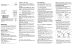
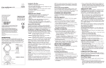
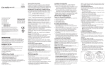
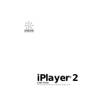
ColorBlaze 48,
ColorBlaze 72
I N S T A L L A T I O N
G U I D E
Scope of This User Guide
Install Power Plug
The goal of this user guide is to explain in easily understood language
the necessary steps to install ColorBlaze and assure peak performance.
Its intended use is for reference only, by fully qualified professionals.
This document should never be considered a substitute for any provisions of a regulation or state and/or local code.
The on-board, auto-switching power supplies automatically adjusts
to any 50 - 60 Hz AC power source from 110 to 240 volts. Install
a 2-pole, 3-wire, grounded, 15A plug to the power cable. Consult a
qualified electrician if in doubt about proper plug installation.
Following the plug manufacturer’s instructions, connect the green
and yellow wire to ground (earth), the black wire to live, and the
white wire to neutral.
Wire
Pin
Marking
Identification and Warnings of Safety Hazards
In accordance with ANSI Z535.4 the following system of identifying
the severity of the hazards associated with the products is used:
“DANGER” Imminently hazardous situation which, if not avoided,
will result in death or serious injury.
“WARNING” Potentially hazardous situation that, if not avoided,
could result in death or serious injury.
“CAUTION” Potentially hazardous situation that, if not avoided, may
result in minor or moderate injury or property damage.
WARNING: The ColorBlaze power plug must be installed by a qualified professional in accordance with NEC and relevant local codes.
Failure to comply can result in death, serious injury, or property
damage.
WARNING: Do not attempt to install or use ColorBlaze until you read
and understand the installation instructions and safety labels.
Failure to adhere to these instructions could result in serious injury or
property damage.
Color Kinetics Incorporated
10 Milk street, Suite 1100
Boston, MA 02108 USA
Tel 888 Full RGB
Tel 617 423 9999
Fax 617 423 9998
[email protected]
www.colorkinetics.com
ITEM# 116-000007-00
116-000007-01
116-000008-00
116-000008-01
(ColorBlaze
(ColorBlaze
(ColorBlaze
(ColorBlaze
72,
72,
48,
48,
Black)
White)
Black)
White)
WARNING: As dictated by a Structural Engineer and/or local code,
install safety cables to ColorBlaze fixtures. Failure to do so can
result in injuries or property damage.
U.S. PATENTS 6,016,038, 6,150,774 AND 6,340,868
EUROPEAN PATENT 1,016,062
OTHER PATENTS PENDING
©2003 Color Kinetics Incorporated. All rights reserved. Chromacore, Color Kinetics,
the Color Kinetics logo, ColorBlast, ColorBurst, ColorPlay, ColorScape, iColor, iColor
Cove, iPlayer, QuickPlay, and Smartjuice are registered trademarks, and Chromasic,
ColorBlaze, and Optibin are trademarks of Color Kinetics Incorporated.
PUB-000092-00 Rev. 02
Specifications subject to change without notice.
Introduction
Welcome to a more colorful world brought to you by Color Kinetics
and Chromacore®, our patented core technologies that generate
and control millions of colors and a variety of lighting effects using
a microprocessor to control LEDs. This guide contains important
information about installing and operating your new ColorBlaze™
safely.
ColorBlaze Detail
END VIEW
FRONT VIEW
BACK VIEW
DATA
INPUT/OUTPUT
AIR FILTER
5
1
4
2
3
POWER
CABLE
MOUNTING
BRACKET
5
1
4
2
3
ON-BOARD
ADDRESSING
LOCKING
KNOB
WARNING: When using safety cables, ensure that they comply to the
specifications given in this user guide. Failure to comply can result
in injuries or property damage.
WARNING: Do not use ColorBlaze if the power cable is damaged.
Doing so can result in death, serious injury, and property damage.
CAUTION: ColorBlaze is on indoor only rated product, do not operate outdoors. Doing so can result in property damage.
CAUTION: Use ColorBlaze in ventilated area with at least 3-inches of
open air on all sides. Failure to do so can result in property damage.
CAUTION: ColorBlaze has no serviceable parts. Do not attempt to
open the fixture. Doing so will result in property damage and void
the warranty.
CAUTION: Do not use sharp tools near or on the fixture lens. Doing
so will result in property damage and void the warranty.
NOTE: The instructions and precautions set forth in this user guide
are not necessarily all-inclusive, all conceivable, or relevant to all
applications as Color Kinetics cannot anticipate all conceivable or
unique situations.
Owner/User Responsibilities
Preparing ColorBlaze for Use
•
•
•
•
1. Attach mounting brackets
2. Install the power plug.
3. Address the light segments.
4. Connect data.
5. Mount and aim the fixture.
ColorBlaze
(2) Mounting brackets and knobs
Warranty and Registration cards
Installation Guide
Additional items needed:
• Mounting base hardware
• Data cables: RJ45 or XLR-5
• Power plug
• Controller - Color Kinetics or DMX compatible
Attach Mounting Brackets
To attach the mounting brackets, insert the
locking knob through the mounting bracket
and rubber washer into the housing.
Tighten locking knob by hand.
Live
“L”
White
Neutral
“N”
Green/Yellow
Ground
Address the Light Segments
Important: Before addressing the ColorBlaze , you must connect
the power plug and supply power to the fixture.
ColorBlaze uses direct DMX data and features on-board addressing
tools.
TEST
Using an RJ45 or XLR-5 data cable, connect data directly from a
DMX controller to the DMX DATA IN ports on the back of the
ColorBlaze . Data can be daisy chained to multiple fixtures by connecting the DMX DATA OUT port to the DMX DATA IN port of the
next fixture using an RJ45 or XLR-5 data cable.
DMX
DATA IN
DMX
DATA OUT
5
Before addressing the ColorBlaze, consider the following:
• The number of desired DMX addresses (address groups) per fixture.
5
1
XLR-5
DATA OUT
JR45
DATA IN
4
2
3
3
XLR-5
DATA IN
5
1
4
2
4
2
3
DMX
DATA OUT
DMX
DATA IN
5
1
4
2
3
RJ45
DATA OUT
• Each light group uses three DMX channels
• The DMX Start Channel for the fixture. The defined light groups
auto-address sequentially beginning with the DMX Start Channel.
To use multiple ColorBlaze fixtures in a sequential application, it
is necessary to calculate the last channel used on the previous fixture to determine the DMX Start Channel for the next fixture.
Setting the Address Groups:
The first step in addressing the fixture is to set the number of groups. Using the “NUMBER OF GROUPS”
selection button, press + or - to scroll to the number of
groups for the fixture. Refer to the table below.
NUMBER OF GROUPS
ColorBlaze 48
GROUP 1
001
2 = Two DMX addresses set to two groups of four segments
GROUP 1
GROUP 2
001
004
DMX
DATA IN
5
1
4
2
3
XLR-5
DATA IN
DMX
DATA IN
DMX
DATA OUT
5
1
4
2
3
JR45
DATA IN
5
1
4
2
3
JR45
DATA IN
5
1
4
2
DMX
DATA OUT
3
XLR-5
DATA OUT
Things to remember:
• DMX data chains need not be connector specific. For example:
XLR-5 input with RJ45 output and vice versa.
• Maximum DMX data run from DMX source to last fixture in chain
is 1000 feet (300 m).
• Place a data terminator in the DMX data port of the last fixture in
a chain.
1 = All segments set to the same DMX address
4 = Four DMX addresses set to four groups of two segments
GROUP 1
GROUP 2
GROUP 3
GROUP 4
001
004
007
010
A = Eight individual DMX addresses
GROUP 1
GROUP 2
GROUP 3
GROUP 4
GROUP 5
GROUP 6
GRP 7
GRP 8
001
004
007
010
013
016
019
022
ColorBlaze 72
1 = All segments set to the same DMX address
Mount and Aim the Fixture
The ColorBlaze mounting brackets are designed for 1/2” mounting
hardware and for use with pipe clamps and Cheeseborough
clamps.
Mount the fixture as dictated by local or state code. Attach safety
cables in suspended installations.
Attaching the safety cable
2 = Two DMX addresses set to two groups of six segments
GROUP 1
GROUP 2
001
004
END USER SPECIFIES
3 = Three DMX addresses set to three groups of four segments
GROUP 1
GROUP 2
GROUP 3
001
004
007
4 = Four DMX addresses set to four groups of three segments
GROUP 1
GROUP 2
GROUP 3
GROUP 4
001
004
007
010
GROUP 1
GROUP 2
GROUP 3
GROUP 4
GROUP 5
GROUP 6
001
004
007
010
013
016
A = Twelve individual DMX addresses
GRP 1
GRP 2
GRP 3
GRP 4
GRP 5
GRP 6
GRP 7
GRP 8
GRP 9
GRP 10
GRP 11
GRP 12
001
004
007
010
013
016
019
022
025
028
031
034
*Example assumes start channel is 001 with three DMX channels per group.
Setting the DMX Start Channel:
MOUNTING
After addressing the segments, press and hold the test button.
Each light segment flashes white sequentially to verify that each
segment is receiving power and data, that the control boards
are functioning, and that the LEDs are operational.
1
6 = Six DMX addresses set to six groups of two segments
LOCKING
KNOB
Testing the lights:
Things to Consider:
001
RUBBER
WASHER
Example: “NUMBER OF GROUPS” set to 3, “DMX START CHANNEL” set to 007: The first four light segments (first group) is set to
007, the next four light light segments (second group) set to 010,
and the last four light segments (third group) set to 013.
Connect Data
GROUP 1
It is the responsibility of the contractor, installer, purchaser, owner,
and user to install, maintain, and operate ColorBlaze in such a
manner as to comply with all state and local laws, ordinances, regulations, and the American Standard Institution Safety Code.
Included in this box:
Black
other groups auto-address sequentially beginning with the DMX
address entered. See DMX table on back.
After setting the number of groups, set the DMX
start channel. Using the “DMX START CHANNEL”
selection button, press + or - to enter the DMX channel for the first, or only, light group in fixture. All
DMX START CHANNEL
REQUIRED END TERMINATOR
Loop the safety cable through the
AND ANCHORING
restraining holes located at each
end of the ColorBlaze housing.
Securely anchor safety cable
SAFETY CABLE
according to local and/or state
codes.
The safe cables used in the installaRESTRAINING HOLE
tion shall meet the following minimal
requirements:
MATERIAL AND DIMENSION: Determined by installer and/or owner.
BREAK LOAD: The minimum break load for the cable and all cable
anchoring construction is 600 pounds, total, minimum break
strength.
CONSTRUCTION: 7 x 7 (49 wires) pre-formed stranded.
END TERMINATOR: Determined by installer and/or owner.
MOUNTING METHOD:
Cleaning ColorBlaze
Determined by installer and/or owner.
WARNING:
To prevent mounting failure, ensure end cap screws are
in place and tight, ensure mounting hardware is properly attached
and tight, and use safety tether cables. Failure to do so can result
in serious injury and property damage.
Aiming the fixture
Loosen the locking handles located at each end of the ColorBlaze.
The fixture will rotate freely. Rotate the fixture to desired position
then tighten the locking handles.
Using ColorPlay with ColorBlaze
ColorPlay™ is an excellent tool for creating beautiful light shows for
ColorBlaze. The trick is in the mapping. After setting the “Number
of Groups” and the DMX Channels for the ColorBlaze 72 fixture,
you are ready to map the light.
1. From the LIGHT PALETTE, click a light icon then drag and drop it
into the MAPPING GRID.
2. Double click the icon. The LIGHT PROPERTIES dialog box appears.
Using the radial button, select DMX CHANNEL NUMBER.
Set the DMX start channel for the fixture. Click OK.
3. Continue dragging icons to the mapping screen--one for each
group on the fixture.
ColorPlay will automatically assign the next available light number, comprising three DMX channels, to each mapped light icon.
4. After mapping the ColorBlaze lights, continue creating light
shows using the TIMELINE EDITOR, then download the show using
the DOWNLOAD screen.
Refer to the ColorPlay User Guide for complete instructions and
tutorials for creating light shows.
Note: Exercise caution when using the Group command in
ColorPlay. Creating groups in ColorPlay can override groups settings on the ColorBlaze fixture.
To protect the clear polycarbonate lens, use caution when cleaning
the ColorBlaze . Use water and a mild detergent with a soft cleaning cloth to wipe the fixture clean.
LIGHT #
DMX #
LIGHT #
DMX #
LIGHT #
DMX #
LIGHT #
DMX #
LIGHT #
1
1
103
35
205
69
307
103
409
137
4
2
106
36
208
70
310
104
412
138
7
3
109
37
211
71
313
105
415
139
WARNING:
Do not operate ColorBlaze without the air intake filter in
place. Doing so presents a risk of electric shock and a risk of fire.
CAUTION:
Do not use paper towels, abrasive cleaning products, or
window cleaners. Abrasive cleaning products will scratch the lens,
and window cleaners will soften the polycarbonate allowing even
soft paper towels to mar the finish.
Clean ColorBlaze housing regularly.
CAUTION: To prevent overheating, ensure that ColorBlaze housing
heat fins are free of debris and heavy dust.
FILTER
SCREWS
WASHERS
GASKET
Cleaning Air Intake Filter
1. Disconnect power. Never attempt to service ColorBlaze with the
power connected.
2. Rotate ColorBlaze to access the air intake filters.
3. Remove the four screws which hold the filter in place.
4. Using the tab, lift the filter to remove it.
Exercise caution to prevent the washers or screws from falling
into the housing opening.
5. Using water, clean the filter then completely dry.
5
1
WARNING: Disconnect power before removing air intake filters.
Failure to do so can result in electrocution and property damage.
NOTE: Capacitors in ColorBlaze can hold a charge after power is
disconnected. Do not insert anything into filter opening.
5
1
4
2
16 AWG STRANDED
(0.82 mm2)
4
2
3
3
DATA CABLE
FROM CONTROLLER
TO DATA IN
5
1
10
4
112
38
214
72
316
106
418
140
13
5
115
39
217
73
319
107
421
141
16
6
118
40
220
74
322
108
424
142
19
7
121
41
223
75
325
109
427
143
22
8
124
42
226
76
328
110
430
144
25
9
127
43
229
77
331
111
433
145
28
10
130
44
232
78
334
112
436
146
1
5
2
4
DMX
DATA IN
3
5
1
5
1
4
2
11
133
45
235
79
337
113
439
147
12
136
46
238
80
340
114
442
148
37
13
139
47
241
81
343
115
445
149
40
14
142
48
244
82
346
116
448
150
43
15
145
49
247
83
349
117
451
151
46
16
148
50
250
84
352
118
454
152
49
17
151
51
253
85
355
119
457
153
52
18
154
52
256
86
358
120
460
154
55
19
157
53
259
87
361
121
463
155
58
20
160
54
262
88
364
122
466
156
61
21
163
55
265
89
367
123
469
157
64
22
166
56
268
90
370
124
472
158
67
23
169
57
271
91
373
125
475
159
70
24
172
58
274
92
376
126
478
160
73
25
175
59
277
93
379
127
481
161
76
26
178
60
280
94
382
128
484
162
79
27
181
61
283
95
385
129
487
163
82
28
184
62
286
96
388
130
490
164
85
29
187
63
289
97
391
131
493
165
88
30
190
64
292
98
394
132
496
166
91
31
193
65
295
99
397
133
499
167
94
32
196
66
298
100
400
134
502
168
97
33
199
67
301
101
403
135
505
169
100
34
202
68
304
102
406
136
508
170
3
DATA CABLE
FROM DATA OUT
TO DATA IN
ON NEXT FIXTURE
DMX
DATA OUT
CONTINUE DMX OUT/IN
SEQUENCE TO INCLUDE ALL
FIXTURES IN CHAIN, THEN
TERMINATE THE LAST.
(SEE NOTES)
4
2
3
3
XLR-5
DMX
DATA IN
DMX
DATA OUT
5
1
DMX
DATA OUT
5
1
4
2
3
5
1
4
2
3
5
1
4
2
3
5
1
DATA CABLE
FROM CONTROLLER
TO DATA IN
(SEE NOTES)
5
4
2
3
5
4
2
DATA CABLE
FROM DATA OUT
TO DATA IN
ON NEXT FIXTURE
DMX
DATA OUT
1
3
5
1
4
2
3
RJ45 8-PIN
(VIEW FACING PINS)
5
1
4
2
3
DETAIL B
22º
DATA INTERFACE
Color Kinetics full line of controller products
PACKAGING
Black or white extruded aluminum housing
CONNECTORS
2-pole, 3-wire, grounded, 15A (not included)
LISTINGS
UL listed to both US and CSA standards, CE certified
POWER REQUIREMENT
100-240VAC (420W)
Color Kinetics illumination products utilize high brightness LEDs as the illumination source. LED manufacturers predict LED life of up to 100,000 hours MTBF (mean time between failure), the standard
used by conventional lamp manufacturers to measure source life. However, like all light sources, LEDs
also experience lumen depreciation over time. So while LEDs can emit light for an extremely long period of time, MTBF is not the only consideration in determining useful life. LED lumen depreciation is
affected by numerous environmental conditions such as ambient temperature, humidity and ventilation.
Lumen depreciation is also affected by means of control, thermal management, current levels, and a
host of other electrical design considerations.
U.S. AND FOREIGN PATENTS AND PATENTS PENDING
CONTINUE DMX OUT/IN
SEQUENCE TO INCLUDE ALL
FIXTURES IN CHAIN, THEN
TERMINATE THE LAST.
(SEE NOTES)
NOTES:
DATA CABLE
(CAT-5 UTP 24AWG 4 PAIR)
High intensity power LEDs
BEAM ANGLE
Color Kinetics systems are expertly engineered to optimize LED life when used under normal operating
conditions [ambient temperature: -4ºF to 104ºF (-20ºC to 40ºC), humidity: 0-95% non-condensing
humidity, adequate ventilation and air volume] and when operated using typical color-changing
effects. Long-term operation outside of these ranges or conditions, or at the upper limits of these
ranges or conditions, may subject the product to further degradation of the LED source life, or in
extreme cases, failure of internal components. Source life information is based on LED manufacturers'
data, as well as other third party testing.
DETAIL C
DMX
DATA IN
SOURCE
3
1
1 2 34 56 78
16.7 million (24bit) additive RGB colors
Continuously variable intensity output range
4
2
RJ45 DATA CONNECTION
PIN 1 DATA PIN 2 DATA +
PIN 3 SHIELD
COLOR RANGE
SOURCE LIFE
3
DETAIL A
AC POWER CONNECTION
100-240V
2 POLE, 3 WIRE
GROUNDED
20A PLUG
16 AWG STRANDED
(0.82 mm2)
For additional heat protection the ColorBlaze is equipped with a fan
control. At elevated ambient temperatures the fan engages at 1/2 RPM.
If ambient temperature continues to increase, the fan will go to full
speed to protect the circuitry and ensure long life of the fixture.
If any problems occur during usage, unplug the product immediately
and call or email:
Color Kinetics Technical Support Group:
1-888-FULL RGB or 617-423-9999 or
[email protected]
4
2
DMX
DATA IN
DATA CABLE
Fan Control
5
1
4
3
34
4
2
3
2
31
5
1
4
2
SHIELD
DATA DATA +
N.C.
N.C.
If strobe lights are used, some international regulatory agencies1 recommend keeping flicker rates at or below four flashes per second
(as less of the flicker-sensitive population will then be at risk of an
attack). This flicker rate applies only to the overall output of any
group of lights in direct view. However, when more than one strobe
light is used, the flashes should be synchronized. End users should
also consider issuing a warning, alerting audience or viewers to the
presence of strobe lighting.
COLORBLAZE SPECIFICATIONS
XLR-5 DATA CONNECTION
PIN 1
PIN 2
PIN 3
PIN 4
PIN 5
Strobe Warning
There is some anecdotal evidence that strobe lighting may induce
epileptic symptoms in certain susceptible individuals, although no
associated product warnings have been issued by United States
government according to the Food and Drug Administration.
For protection from extreme temperatures, the ColorBlaze has been
designed with a temperature monitoring feature. If operating temperatures rise to an unsafe level, a compensation circuit is triggered and the
operation of some or all light segments is interrupted causing the lights
to turn dull red. After 30 minutes the lights will auto-cycle and return to
full intensity.
To prevent additional power shut-downs, determine the cause of the
overheating and correct the problem.
Wiring Diagram
AC POWER CONNECTION
100-240V
2 POLE, 3 WIRE
GROUNDED
20A PLUG
Important Information
Temperature Monitoring
To prevent overheating, inspect air intake filter frequently and clean
as needed. The air intake filters are located near each end, on the
back of the ColorBlaze fixture.
DMX TABLE
DMX #
6. Replace the filter, ensuring that gasket and washers are in place.
Refer to the following illustration.
1. PLACE TERMINATOR IN DMX DATA OUT PORT OF THE LAST FIXTURE IN A CHAIN.
2. MAXIMUM DMX DATA RUN FROM DMX SOURCE TO LAST FIXTURE IN CHAIN IS 1000 FEET (OR 300 m).
3. DMX DATA CHAINS NEED NOT BE CONNECTOR SPECIFIC, FOR EXAMPLE: XLR-5 INPUT WITH RJ45
OUTPUT AND VICE VERSA. SEE DETAIL C.
4. AUXILIARY POWER JACK IS FOR USE WITH COLOR KINETICS PRODUCTS ONLY.
Color Kinetics Incorporated grants the purchaser of its lighting products and controllers a personal and
non-transferable license to use Chromacore®, its patented technology for networkable control of LEDbased color changing lighting fixtures for illumination, display and design. This license is granted only
by Color Kinetics Incorporated, and may not be transferred except by the grantor. The design, duplication, manufacture, or sale of other products using networkable control of LED-based color changing
lighting may be prohibited and is not licensed hereunder. Other patents pending.
1
Guide to Health, Safety and Welfare at Pop Concerts and Similar Events, HMSO Publications (UK)