1
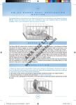
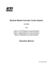
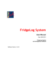
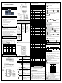
LZ-803E07
4
For 96×48mm:
WEIGHT DISPLAY CONTROLLER
LZ-803 SERIES
4
For 72×72mm:
FOR YOUR SAFTY, PLEASE READ THIS MANUAL CAREFULLY
SAFETY CAUTION
Please do not use on equipments such as atomic energy equipment, medical equipments, or other
equipments related to the life.
l
There is no fuse in the controller, please set the safe circuit break components like fuse in the
external power supply circuit.
INPUT WIRE CONNECTION
l
Please do not use the product besides the standard specification.
l
Please do not use in the flammable and explosive places.
l
Please avoid installing the product at right above large energy instruments such as heater,
transformers, and high power resistance.
( 2) Wiring for mV
(3) Wiring for 2-wire
(1)Wiring of AC and DC
signal of Strain Bridge
Input
AC Transmitter
or Diffusion Silicon
WANRING
l
When the ambient temperature reaches above 50℃, please use fan or cooler to cool it, but do not let
the cool air blow directly to the product.
l
For panel installed controller, please take necessary measure to prevent user accessing high-voltage
compartment such as power supply terminal.
l
Please install, calibrate and maintain the product by the qualified engineering technician.
l
If the product failure or abnormal could lead to a major system accident, please set appropriate
protection circuit on external to prevent the accidents.
l
We are responsible for any direct or indirect loses other than the product itself.
l
We reserve the rights to any change of product manual prior any notice
( 4 ) Wiring for 3-wire
DC/AC Transmitter
PANEL DIMENSION
Dimensions:
Mount Dimensions:
SETTING
1. PANEL AND KEY DESCRIPTION
SPECIFICATION a (mm) b (mm) c (mm) d (mm) e (mm) f (mm) g (mm)
160×80
160
80
10
115
75
152-1
76-1
96×96
96
96
12
100
91
92-0.5
92-0.5
96×48
96
48
12
100
43
92-0.5
45-0.5
72×72
72
72
12
100
67
68-0.5
68-0.5
(Take 96×96mm for example)
WIRING
4
For 160×80mm:
4
For 96×96mm:
3.1 Setting for Alarm Setting Value
4
Alarm setting value is in the first group parameter. And controller with no alarm
function has no such group parameter.
① Press
key for 2 seconds to enter the setting, and it displays the first parameter
symbol.
key to enter other parameter of this group in order.
② Press
③ Press
key to pull the original setting value of the current parameter, the
flashing place is the editing place.
key to change the editing place,
key for increase, and
key for
④ Use
decrease to enter the needed value.
key confirm and enter the next parameter. If it is the last parameter of
⑤ Press
this group, after press
key, it will exit the setting status.
Repeat step ② ~ ⑤ to set the other parameter of this group.
First Group Parameter: Alarm Setup Value
Symbol
USER MANUAL
l
2. PARAMETER DESCRIPTION
Name
Description
Ÿ Display measured/peak/valley value
①Measured Value
ŸDisplay parameter symbol and value under the
Display Display
parameter setting status
Screen
②Alarm
Set
Ÿ Display alarm set value/peak/valley value
Display
③ Indicator Light
Ÿ Display alarm status of each alarm point
ŸUnder measuring status, press for 2s until it
enters setting status; and when the screen shows
④ Setup Key
parameter symbol, press for 2s until it enters next
group parameter or back to the measuring status.
ŸUnder measuring status, to reset peak/valley
value(
= )
⑤ Left Key
ŸUnder measuring status: ① pull the original
parameter value; ② shift editing place
ŸUnder measuring status, switch among measured
Function
⑥Confirm Key
value, peak value, and valley value(
= )
Key
ŸUnder measuring status, record the edited
parameter value
Ÿ Invalid under measuring status
⑦Increase Key
Ÿ Under measuring status, increase parameter
value or change setting type
ŸUnder measuring status, to reset the measured
⑧ Decrease Key value
ŸUnder measuring status, decrease parameter
value or change setting type
Name
Description
Address
Value Range
00H
-1999~9999
Av
Comparative value of bias alarm mode
AH
1st alarm setting value
01H
-1999~9999
AL
2nd alarm setting value
02H
-1999~9999
AHH
3rd alarm setting value
03H
-1999~9999
ALL
4th alarm setting value
04H
-1999~9999
4 Second Group Parameter: Alarm Setup Configuration
Symbol
Name
Description
Address
Value Range
oA
Password
10H
0~9999
ALo1
Alarm mode at 1st alarm set point
11H
Note 1
ALo2
Alarm mode at 2nd alarm set point
12H
Note 1
ALo3
Alarm mode at 3rd alarm set point
13H
Note 1
ALo4
Alarm mode at 4th alarm set point
14H
Note 1
HYA1
Sensitivity at 1st alarm set point
19H
0~8000
nd
HYA2
Sensitivity at 2 alarm set point
1AH
0~8000
HYA3
Sensitivity at 3rd alarm set point
1BH
0~8000
HYA4
Sensitivity at 4th alarm set point
1CH
0~8000
cYt
Alarm Delay
1FH
0 ~ 20
4 Third Group Parameter: Break Line Calculation
Symbol
Name
Description
Address
Value Range
c1
Measured value of 1st break point
20H
-1999~9999
b1
Standard value of 1st break point
21H
-1999~9999
nd
c2
Measured value of 2 break point
22H
-1999~9999
b2
Standard value of 2nd break point
23H
-1999~9999
c3
Measured value of 3rd break point
24H
-1999~9999
b3
Standard value of 3rd break point
25H
-1999~9999
c4
Measured value of 4th break point
26H
-1999~9999
b4
Standard value of 4th break point
27H
-1999~9999
c5
Measured value of 5th break point
28H
-1999~9999
b5
Standard value of 5th break point
29H
-1999~9999
th
c6
Measured value of 6 break point
2AH
-1999~9999
b6
Standard value of 6th break point
2BH
-1999~9999
c7
Measured value of 7th break point
2CH
-1999~9999
b7
Standard value of 7th break point
2DH
-1999~9999
c8
Measured value of 8th break point
2EH
-1999~9999
b8
Standard value of 8th break point
2FH
-1999~9999
4 Fourth Group Parameter: Measurement and Display
Name
Description
Address
Value Range
Symbol
incH
Input signal option
30H
0~7
in-d
Display decimal places option
31H
Note 2
u-r
Lower limit of measuring range
32H
-1999~9999
F-r
Upper limit of measuring range
33H
-1999~9999
in-A
Zero modified value
34H
-1999~9999
Fi
Full scale modified value
35H
0.500~1.500
FLtr
Time constant of digital filtering
36H
1 ~ 20
c-b
Broken line function option
37H
Note 3
Zror
Zero reset range
38H
0 ~ 9999
Zrot
Valid time for pressing zero reset
39H
0~6
At
Display update rate
3AH
1~60
bout
Fault substitute value
3CH
-1999~9999
HL
Setting value display option
3DH
0 ~6
Fbc
Working mode
3EH
Note 3
Fbao
1st screen display option
3FH
0~3
4
Fifth Group Parameter: Communication Interface, and Transmitting Output, etc
Symbol
Name
Description
Address
Value Range
Add
Controller communication address
40H
0 ~ 99
bAud
Baud rate option
41H
Note 4
Option for right of control to alarm
ctd
44H
Note 3
signal output
Option for right of control to
ctA
45H
Note 3
transmitting output
oA1
Password option for alarm set
46H
Note 3
oP
Output signal option
4DH
0~2
bA-L
Lower limit of transmitting output
4EH
-1999~9999
bA-H
Upper limit of transmitting output
4FH
-1999~9999
Note 1: “0 ~ 4” represents 5 types of alarm modes from
to
, respectively.
Note 2: “0 ~ 3” represents .
, . ,
. ,
., respectively.
Note 3: “0” for “OFF”; “1” for “ON”.
Note 4: “0 ~ 3” represents “2400,4800,9600,19.2k” , respectively.
3. PARAMETER SETTING
The parameter has been divided into several groups, and each parameter of every group is
listed in above PARAMETER DESCRIPTION table.
★ The 2nd group parameter and after are controlled by password, so it cannot be accessed without
password setting.
★Set
parameter can decide if 1st group parameter is controlled by password. When
is set “OFF”, it is not controlled by password; when it is “ON”, if the password is not
set yet, the parameter setting can be accessed and edited but can be stored.
★After entering setting status, if there is no operation over 1min, it will exit the setting
status.
3.2 Password Setting
When the controller is at measuring status or displaying first group parameter, it can
set the password.
① Press the setting key
② Press
until it shows
.
,
key to enter the edit mode, use
,
keys to enter “1111”.
③ Press
key to confirm.
★ When the controller is connected to power supply or there is no operation over 1
min, the password will be reset to zero.
3.3 Other Parameter Setting
① To set the password first.
② Password parameter is in the second group parameter. After setting password, press
key to choose other parameter in this group.
③ To set other group parameter, press
key until it enters each group parameter in
order, and it displays the first valid parameter symbol of that group.
key to choose to set the
④ After enter the needed setting parameter group, press
parameter of that group in turns.
⑤ Press
key pull the original setting value of the current parameter, the flashing
place is the editing place.
⑥ Use
key to change the editing place,
key for increase, and
key for
decrease to enter the needed value.
★ The parameter value is in symbolic form. The flashing place should be the last point
when editing.
⑦ Press
key to confirm and enter the next parameter.
Repeat step ④ ~ ⑦ to set other parameter of that group.
EXIT SETTING:When displaying the parameter symbols, press
until it exits the
parameter setting status.
FUNCTION PARAMETER DESCRIPTION
1 MEASURING AND DISPLAY
The processing procedures from sampling to display:
Sampling
→
Digital Filtering
Calibration → Broken Line Calculation
Value Measurement
→
→
Dimensional Transformation
→ Zero Reset →
→
Peak and Valley
Display
4
Dimensional Transformation: the conversion of Voltage, Current and mV signal
between the upper and lower limit of the set measuring range.
In particular cases, it can be converted based on the provided comparison table
or equation of signal and display by customer.
4 Calibration: please see CALIBRATION for more detail.
4 Broken Line Calculation: please see 8 SECTIONS OF BROKEN LINE
CALCULATION FUNCTION for more detail.
Below is the parameter of measuring and display. If the setting is not correct, the
controller may not display normal.
Display is also affected by calibration and broken line calculation
4
(incH)—— Input Signal Option
The set value should comply with the controller model and the actual input signal. The
parameter value is in symbol form and table below has listed their correspondence:
0
4mA~20mA
1
0mA~10mA
2
0mA~20mA
3
1V~5V
4
0V~5V
5
±20mV
6
±50mV
7
±90mV
4
(in-d)—— Displayed decimal place option of measuring value
4
(u-r)—— Lower limit of measuring range
4
(F-r)—— Upper limit of measuring range
The two parameter specifies that the beginning and end point of input signal
corresponds to the beginning and the end point of the display value.
4
(FLtr)—— Time Constant of Digital Filter
It is used to overcome the display fluctuate of unstable signal, the bigger of the set
value, the stronger of the effect but slower the responds. The default value is “1”.
(At)—— Display Refresh Rate
4
The sampling rate of the controller is 10times/second.
parameter’s setting value is
that the display update 1 time needs the sample numbers of undergoing average
is set to 5, the display updates 1 time after the 5 times
calculation. E.g. when
sampling values take the average calculation.
The period of alarm and transmit output is also 10times/second, which is unrelated to this
parameter.
4
(HL)—— The display option of second screen.
The controller with set value display can display any certain set value through this
parameter option.
”, “
“0~6” represent “ ”, “ ”, “ ”, “
、”, “Peak Value” and “Valley Value”.
4.
ZERO RESET
(Zror)——Zero reset range, the default is “0”
4
4
(Zrot)——Valid time for pressing zero reset.
The set range is 0-6 second,when the set value is “0”, the measuring value is in the range
of zero reset, press to reset.
Under measuring status, the measuring value is in the range of zero reset, there are 3 ways
to realize zero reset of the measuring value:
① Press
key for a certain time(time is decided by
setting)to zero reset
② Zero reset from rear terminal for a certain time ( time is decided by
setting),the measured value reset to zero;
③ To zero reset from the host computer through communication interface.
5. MEASURMENT OF PEAK VALUE AND VALLEY
VALUE
4
(Fbc)—— Operating mode option
is set,it is working in normal mode and only has measuring value;
When
When
is set, it is working at Peak/Valley value mode, and measuring Peak/Valley
value.
4
(Fbc)—— Display options
When “0” is set, the first screen displays measuring value;
When “1” is set, press
is set, 1st screen displays measuring value and peak value;
When “2” is set, press
is set, 1st screen displays measuring value and valley value;
When “3” is set, press
is set, 1st screen displays measuring value and peak and valley
value.
Under the peak/valley value mode, peak/valley value has been detected by each
measurement and control period. Press
to change the mode among measuring value,
peak value, and valley value on 1st screen. And when displaying peak/valley value, the
bottom decimal point is bright on 1st screen.
Under measuring status,
= ,there are 2 ways to reset peak/valley value:
① Press
Key to reset peak/valley value;
② From the host computer through communication interface to reset.
Note:
When
=
,
parameter is invalid, but
should be set as
“0~4”
6. 8 SECTIONS OF BROKEN LINE
CALCULATION FUNCTION
This function is an optional function.
When input signal is only rising nonlinear with the displayed data, and the data can be sure
when order so it needs amendment in calibration, under this circumstance, the broken line
calculation function can be used.
Only rising means that within the input signal range, the input signal increases, the
displayed data increases as well.
○1 The parameter of Broken Line Calculation:
(c-b)—— Broken line function option
4
~
:measured value of each broken line point
4
~
:standard value of each broken line point
4
Measured Value: the displayed value before broken line calculation;
Standard Value: the expected display value after broken line calculation.
② Application Method
· Broken line calculation is performed after dimensional transformation and calibration,
and it should be set according to the parameter of CALIBRATION
· Set
parameter as “OFF” to turnoff the broken line calculation function.
· After input signal is received, during the process of increase the input signal from small to
large, the measured value and standard value of each broken line have been recorded as
~
,
~
.
· Set
~
parameter is “ON” to turn on the broken line calculation function to set
,
~
parameter.
③ Diagram
·Parameter setting
·Output switch value
★ Measured value less than C1 is calculated down recursion at the latter section
data;
★Measured value larger than C8 is calculated down recursion at the latter section
data.
7. ALARM OUTPUT
This function is an optional function.
It can be set max. 4 alarm point. Each alarm point has 3 parameter for setting
alarm value, alarm mode option and setting alarm sensitivity, respectively.
,
,
,
for each alarm set point from 1st to 4th .
4
~
for each alarm mode option from 1st to 4th .
4
for each alarm set sensitivity from 1st to 4th .
~
4
And there are 2 more public parameter for alarm output:
4
(Av)—— Comparative value of bias alarm mode
When the bias between measured value and above value is over the set value, it will
alarm. The non-bias alarm mode is unrelated to this parameter.
4
(cYt)—— Alarm-delay time
The setting range is 0~20 second,there is no alarm-delay function when it is set to
“0”;
When the measured value is over the set alarm value, it starts alarm-delay. And if the
measured value is always in the alarming status under the alarm-delay period, it will
output the alarm signal when the alarm-delay time is over, otherwise there is no
signal.
MODEL DESCRIPTION
·Output analog value
CALIBRATION
For calibration, it has to correct the zero first, and then to amend full scale.
4
(in-A)—— Zero Correction Value, the default is “0”;
4
(Fi)—— Full scale amendment value, the default is “1.000”.
The displayed value =(the displayed value before zero correction +
CONDUCT TO FAULT SIGNAL OF INPUT
problem of the abnormal operation caused by input signal failure, such as interlocking,
shutdown, and etc. When it displays
. which is input signal failure, but it can also process
the parameter setting.
Input signal failure is caused by AD transfer overflow which is resulted by larger input signal.
4
(bout)—— The substitute measured value when input signal failure
When the input signal is deemed as failure/malfunction, the set
~
4 Alarm Mode: 5 modes for each alarm point to be chosen through
parameter;
: for upper limit alarm, it will alarm when the measured value > the set
value
: for lower limit alarm, it will alarm when the measured value > the set
value
: for bias upper limit alarm, it will alarm when (Measured value— )>
the set value;
: for bias lower limit alarm, it will alarm when( —Measured value)>
the set value;
: for bias absolute value alarm, it will alarm when┃
—Measured
value┃> the set value.
Under bias alarm mode, the set value cannot be negative.
4 Alarm sensitivity: to prevent the measured value fluctuating near the set value
resulting frequently operation of alarm relay, it can be set an extension area of
clearing alarm when it is necessary.
The controller with communication function, when
parameter is set
“ON”, it will not alarm.
input value of alarm output and transmit output.
value will be the
This input signal failure alarm function can be added by users’ requirement.
If there is no function of either alarm output, or transmit output, or communication, this
parameter is not functional.
SPECIFICATION
1. General Specification
AC
Power
Supply
AC/DC
AC
Power
Consumption
AC/DC
Allowed Voltage Change Range
Insulation Resistance
100-240 V AC 50/60 Hz
10-24V AC 50/60 Hz;10-24V DC
<7 VA
AC: <6 VA;DC: <5W
90 ~ 110 % supply voltage
>100MΩ(500 V DC MEGA Standard)
1 min under 2000 V AC 50/60Hz
Voltage Resistance
8. TRANSMITTING OUTPUT
Anti-Interference
Protection Class
Temperature
Humidity
Environment
2.
IEC61000-4-2(electrostatic discharge), Class Ⅲ;
IEC61000-4-4( Electrical fast transient burst), Class
Ⅲ;
IEC61000-4-5(surge),Class Ⅲ
IP65(Front part of the product)
-10 ~ 55℃; Storage: -25 ~ 65℃
35 ~ 85 %RH; Storage: 35 ~ 85 %RH
Input Specification
Measuring Control Speed
>10 times/second
Basic Error
±0.2 %F.S
Display Range
-1999~ 9999
V
Voltage
0-5V DC;1-5V DC
Input Signal
Current
I
4-20/0-10/0-20 mA
M
mV
±20、±50、±90 mV
Digital Filter
Inertia; Average value; Moving average, etc
9. COMMUNICATION INTERFACE
This function is an optional function. There are 4 parameter for communication
function:
4
(Add)—— Communication address. The range is 0-99. The default is “1”.
4
(bAud)—— Communication baud rate option. 4 options at 2400,4800,
9600,19.20k . The default is “9600”;
4
(ctd)—— Alarm output right option. The default is “OFF”;
When it is OFF, the controller operates the alarm function; when it is “ON”, the
control right has transferred to computer, the alarm output is controlled directly by
the switch output commend sent by the computer.
4
(ctA)—— Transmit output right option. The default is “OFF”
When it is OFF, the controller operates the transmit output function; when it is
“ON”, the control right has transferred to computer, the transmit output is controlled
directly by the analog output command sent by the computer.
Please see COMMUNICATION PROTOCOL for relative communication
commands and protocols. The commands for the controller are listed as followings:
·Measuring value reading
·Peak value reading
·Valley value reading
·Zero reset of measuring value
·Peak/Valley value reset
·Output analog value reading (transmit output)
·Switch input status reading
·Switch output status reading (alarm output)
·Version number of the controller
·The expressed symbol of controller parameter (Name)
·Parameter value of the controller
Product Model Number
②
Dimension Specification
③
Panel Dimension
④
Input Specification
⑤
These five digits stand for custom requirement
⑥
Optional Parts Specification
⑦
Power Supply Specification: V0 for 220VAC;V1 for 10-24VDC(or AC)
This troubleshooting function can effectively ensure the safe operation and resolve the
Alarm restore is also controlled by the delay time.
This function is an optional function. There are 3 parameter for transmit output:
4
(op)—— Output signal option
Options:
:Output is 4mA -20mA(or1 V -5V)
:Output is 0mA -10mA
:Output is 0mA -20mA(or 0 V -5V; or 0 V -10V)
4
(bA-L)—— Lower limit setting of transmit output
4
(bA-H)—— Upper limit setting of transmit output
The controller with communication function, when
parameter is set
“ON”, it will not transmitting output.
)×
①
3.
Optional Parts Specification
Output of
Terminal Point
Input of
Terminal Point
Analog Output
(Resolution
1/3000)
Communication
Interface
External Power
Supply
T1-T4 1-4 points,250VAC/3A resistive load
K
point 1 of external analog input for zero rest
A1
Current output
A2
S1
S2
M1
M2
B1
B1G
B2
B2G
B3
(4-20)mA,(0-10)mA,(0-20)mA
Voltage output (1-5)V,(0-5)V
TC ASCII Protocol: RS232
Rate:2400;4800;9600;19200
TC ASCII Protocol: RS485
Address: 0 – 99
Modbus-RTU Protocol:RS232 Response Time:500μS
Modbus-RTU Protocol:RS485 (Measured value)
< 24V±5%, 50mA
<24V±5%, 100mA
<12V±5%, 50mA
<12V±5%, 100mA
Precision power supply, normally 10V±2%, under 30ppm,
100mA
with letter“N”in the end,means that this optional parts need to be
customized.