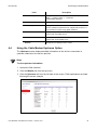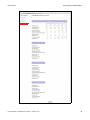
1
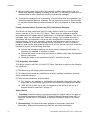
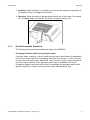
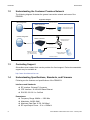
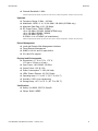
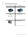
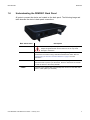
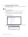
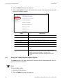
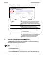
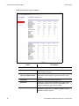
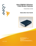
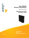
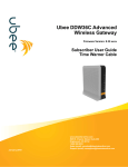
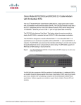
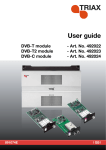
Ubee DDM3521 Cable Modem User Guide February 2013 www.ubeeinteractive.com 8085 S. Chester Street, Suite 200 Englewood, CO 80112 1.888.390.8233 Sales (email): [email protected] Support (email) [email protected] Notices and Copyrights Copyright 2013 Ubee. All Rights Reserved. This document contains proprietary information of Ubee and is not to be disclosed or used except in accordance with applicable agreements. This material is protected by the copyright laws of the United States and other countries. It may not be reproduced, distributed, or altered in any fashion by any entity (either internal or external to Ubee), except in accordance with applicable agreements, contracts, or licensing, without the express written consent of Ubee and the business management owner of the material. Contents 1 Introduction . . . . . . . . . . . . . . . . . . . . . . . . . . . . . . . . . . . . . . . . . . . . . 1 1.1 1.2 1.3 1.4 1.5 1.6 1.7 Understanding Safety and Regulatory Information .......................................... 1 Understanding the Customer Premises Network............................................. 4 Contacting Support .......................................................................................... 4 Understanding Specifications, Standards, and Firmware ................................ 4 Verifying Device Package Components .......................................................... 6 Understanding the DDM3521 Back Panel ....................................................... 7 Understanding the DDM3521 Front Panel and LED Behavior......................... 8 2 Installing and Connecting the DDM3521 . . . . . . . . . . . . . . . . . . . . . 11 2.1 2.2 2.3 2.4 Understanding Minimum System Requirements............................................ 11 Installing the DDM3521 ................................................................................. 12 Connecting Devices to Your Network ............................................................ 12 Troubleshooting the Installation ..................................................................... 13 3 Accessing the Web User Interface . . . . . . . . . . . . . . . . . . . . . . . . . . 15 4 Understanding the Cable Modem Menu. . . . . . . . . . . . . . . . . . . . . . 17 4.1 4.2 4.3 4.4 4.5 4.6 February 2013 Using the Cable Modem Information Option.................................................. 17 Using the Cable Modem Status Option ......................................................... 18 Using the Cable Modem Downstream Option................................................ 19 Using the Cable Modem Upstream Option .................................................... 21 Using the Modem Upstream Burst Option ..................................................... 22 Using the Cable Modem Event Log Option ................................................... 24 www.ubeeinteractive.com 8085 S. Chester Street, Suite 200 Englewood, CO 80112 1.888.390.8233 Sales (email): [email protected] Support (email) [email protected] 1 Introduction Welcome to the Ubee family of data networking products. This document provides instructions for anyone who installs, configures, maintains, and uses the DDM3521 Cable Modem. Ubee recommends that you read this chapter before installing and using the device. The following topics are provided in this section: Topics See the following topics: 1.1 Understanding Safety and Regulatory Information on page 1 Understanding the Customer Premises Network on page 4 Contacting Support on page 4 Understanding Specifications, Standards, and Firmware on page 4 Verifying Device Package Components on page 6 Understanding the DDM3521 Back Panel on page 7 Understanding the DDM3521 Front Panel and LED Behavior on page 8 Understanding Safety and Regulatory Information The following information provides safety and regulatory standards for anyone installing, maintaining, and using the DDM3521. 1.1.1 Safety WARNING: The following information provides safety guidelines for anyone installing and maintaining the DDM3521. Read all safety instructions in this guide before attempting to unpack, install, operate, or connect power to this product. Follow all instruction labels on the device itself. Comply with the following safety guidelines for proper operation of the device: Always follow basic safety precautions to reduce the risk of fire, electrical shock and injury. To prevent fire or shock hazard, do not expose the unit to rain, moisture, or install this product near water. Never spill any form of liquid on or into this product. Do not use liquid cleaners or aerosol cleaners on or close to the product. Use a soft dry cloth for cleaning. Do not insert any sharp object into the product’s module openings or empty slots. Doing so may accidentally damage its parts and/or cause electric shock. Electrostatic discharge (ESD) can permanently damage semiconductor devices. Always follow ESD-prevention guidelines for equipment handling and storage. Use only the power adapter supplied with the device. Do not place heavy objects on top of the device. Ubee DDM3521 Cable Modem User Guide • February 2013 1 Introduction Ubee Interactive Rest the power cable freely without any obstacle or heavy items piled on top of it. Refrain from abusing, stepping or walking on the cable. Do not place the device on an unstable stand or table; the device may drop and become damaged. To protect the equipment from overheating, do not block the slots and openings in the module housing that provides ventilation. Do not expose this device to direct sunlight. Do not place any hot devices close to this device, as it may degrade or cause damage to it. Federal Communications Commission (FCC) Interference Statement This device has been tested and found to comply with the limits for a Class B digital device, pursuant to Part 15 of the FCC Rules. These limits are designed to provide reasonable protection against harmful interference in a residential installation. This device generates, uses, and can radiate radio frequency energy. If not installed and used in accordance with the instructions, the device may cause harmful interference to radio communications. There is no guarantee, however, that interference will not occur in a particular installation. If this device causes harmful interference to radio or television reception, which can be determined by turning it off and on, the user can try to correct the interference by one of the following measures: Increase the separation between the device and the equipment with which it is interfering (for example, a television or radio). Connect the device into an electrical outlet on a different circuit than the interfered device is connected. Consult the dealer or an experienced radio/TV technician for help. FCC Regulatory Information This device complies with Part 15 of the FCC Rules. Operation is subject to the following two conditions: (1) This device may not cause harmful interference. (2) This device must accept any interference received, including interference that may cause undesired operation. (3) There are two statements for this product: FCC Caution: Any changes or modifications not expressly approved by the party responsible for compliance could void the user's authority to operate this device. IEEE 802.11b or 802.11g or 802.11n operation of this device in the U.S.A. is firmware-limited to channels 1 through 11. Safety Notices 1. Grounding: Install the device to include grounding the coaxial cable to the earth at the building entrance per ANSI/NFPA 70 and the National Electrical Code (NEC, in particular, Section 820.93, Grounding of the Outer Conductive Shield of a Coaxial Cable). 2. Disconnecting: If the device becomes damaged or encounters some other abnormality, disconnect the power plug from the wall outlet immediately. 2 Ubee DDM3521 Cable Modem User Guide • February 2013 Ubee Interactive Introduction 3. Installing: Install the device in a location not to exceed the maximum temperature of 40 degrees Celsius (104 degrees Fahrenheit). 4. Mounting: When this device is placed upright with the aid of the stand, fix the stand at a 90-degree angle to the device. Otherwise, the device may tip over. 1.1.2 Eco-Environmental Statements The following eco-environmental statements apply to the DDM3521. Packaging Collection and Recovery Requirements: Countries, states, localities, or other jurisdictions may require that systems be established for the return and/or collection of packaging waste from the consumer, or other end user, or from sewer and waste water. Additionally, reuse, recovery, and/or recycling targets for the return and/or collection of the packaging waste may be established. For more information regarding collection and recovery of packaging and packaging waste within specific jurisdictions, contact Ubee Interactive at www.ubeeinteractive.com. Ubee DDM3521 Cable Modem User Guide • February 2013 3 Introduction 1.2 Ubee Interactive Understanding the Customer Premises Network The following diagram illustrates the general connection network and uses of the DDM3521. Application Diagram Basic Configuration Subscriber Premises DDM3521 Cable Modem Cable RF/Coax Single Computer or Other Ethernet-Enabled Device Ethernet/LAN Connection Common Configuration DDM3521 Cable Modem Cable RF/Coax Wireless Access Point LAN Switch Router Ethernet/LAN Connection Ethernet/LAN Connection Desktop PCs and/or other Ethernet LAN Devices (e.g., Gaming Console) Laptop PC and/or Other Wireless Devices Subscriber Premises 1.3 Contacting Support Subscribers must contact their service provider for direct support. Device documentation support may be available at: http://www.ubeeinteractive.com 1.4 Understanding Specifications, Standards, and Firmware Following are the features and specifications of the DDM3521: Interfaces and Standards RF Interface: External F-Connector CPE Interface: 10/100/1000 Base Ethernet DOCSIS 3.0/2.0./1.x Certified Downstream 4 Frequency Range: 88MHz ~ 1002 MHz Modulation: 64/256 QAM Maximum Data Rate: 8 DS: 343 Mbps* RF Input/Output Power: -15 to +15 dBmV Ubee DDM3521 Cable Modem User Guide • February 2013 Ubee Interactive Introduction Channel Bandwidth: 6 MHz *Maximum Speeds (actual speeds vary based on factors such as network configuration, conditions, and service tier). Upstream Frequency Range: 5 MHz ~ 42 MHz Modulation: QPSK, 8, 16, 32, 64 QAM, 128 QAM (S-CDMA only) Maximum Data Rate 4 US: 122 Mbps* RF Output Power: TDMA /ATDMA: +8 to +54 dBmV (32QAM, 64QAM ATDMA only) +8 to +55 dBmV (8QAM, 16QAM) +8 to +58 dBmV (QPSK) S-CDMA: +8 to +53 dBmV (all modulations) *Maximum Speeds (actual speeds vary based on factors such as network configuration, conditions, and service tier). Device Management Local and Remote Web Management Interface Telnet Remote Management SNMP v1/v2/v2c and v3 agent built-in IPv4 and IPv6 support Physical and Environmental Dimensions: 6.7” W x 6” D x 1.75” H (170 mm x 152 mm x 44 mm) Input Power: 100-120VAC, 50-60Hz Output Power: 12V @ 1.0A Power Consumption: < 10W (full load) LEDs: Power, Ethernet, US, DS, Ready Operating temp: 0˚ C to 40˚ C (32˚ F to 104˚ F) Humidity: 5~95% (non-condensing) Storage temp: -40˚ C to 70˚ C (-40˚ F to 158˚ F) Certifications Safety: UL 60950; CE/FCC Class B Others: RoHS, WEEE Ubee DDM3521 Cable Modem User Guide • February 2013 5 Introduction 1.5 Ubee Interactive Verifying Device Package Components The package for the DDM3521 contains the following items: Item DDM3521 Front View Description DDM3521 Back View 1 - RJ45 Cable (Ethernet) Length ~ 6.0 ft RoHS & UL compliant Sample image, actual appearance subject to change. 1 - Power Adapter AC to DC Power Switching Input Power: 100-120VAC 50/60 Hz 0.3A Output Power: 12V / 1.0Amp Sample image, actual appearance subject to change. 6 Ubee DDM3521 Cable Modem User Guide • February 2013 Ubee Interactive 1.6 Introduction Understanding the DDM3521 Back Panel All ports to connect the device are located on the back panel. The following image and table describe the device’s back panel connections. Back Panel Label Description PWR Connects to the power adapter. WARNING: Use only the power adapter shipped with this device. Failure to do so may cause damage to the device. ETHERNET Connects an Ethernet device such as a computer, gaming console, or a router/hub to the Internet using a standard RJ45 Ethernet cable. See the Understanding the Customer Premises Network on page 4 for more information. RESET Resets the device. Insert a pointed object into the opening. Press for less than10 seconds to power cycle the device. Press for more than 10 seconds to reset the device to the factory defaults. CABLE Connects to the coaxial cable (not included) that comes from the cable wall outlet or cable splitter (not included). Ubee DDM3521 Cable Modem User Guide • February 2013 7 Introduction 1.7 Ubee Interactive Understanding the DDM3521 Front Panel and LED Behavior The DDM3521 has several LEDs that provide the status of the device. The following image and the table describe LED behavior. LED Name Ready DS single US bonded single bonded Ethernet Power Provisioning State Driver init off off off DS scanning off blinks off on DS locked off on off on US ranging off on blinks on US ranged off on on blinks on on IP Init & Registration (& Firmware Upgrade) off Network Access Enabled on on on on on Access Disabled off on on on on green/blue depending on Ethernet connection speed on on on on Operat ional Network Cable interface traffic (network access enabled) on on on on green/blue depending on Ethernet connection speed on Ethernet connected depends on provisioning state on on Ethernet traffic depends on provisioning state blinks on 8 on on GREEN Ethernet LED indicates 10/100 Mbps speed has been negotiated. BLUE Ethernet LED indicates 1000 Mbps speed has been negotiated. LED flashing indicates network traffic on the active port. LED dark indicates no connectivity. Ubee DDM3521 Cable Modem User Guide • February 2013 Ubee Interactive Ubee DDM3521 Cable Modem User Guide • February 2013 Introduction 9 Introduction 10 Ubee Interactive Ubee DDM3521 Cable Modem User Guide • February 2013 2 Installing and Connecting the DDM3521 Use these instructions to install and connect the DDM3521. Topics See the following topics: 2.1 Understanding Minimum System Requirements on page 11 Installing the DDM3521 on page 12 Connecting Devices to Your Network on page 12 Troubleshooting the Installation on page 13 Understanding Minimum System Requirements The following system requirements are for computers connecting to the cable modem and for using the Web interface of the cable modem. PC - Minimum System Requirements Processor 300Mhz Operating System Windows 2000 pro, Windows XP Memory 128 MB RAM Hard Drive 125 MB free space Email Client Outlook Express 5.5/6 Internet Browser Internet Explorer version 5.5, 6 (sp1+sp2) Computer Interface Ethernet card Ethernet based connection (Network Interface Card) that can support 10/100/1000Mbps connection rates Screen Display SVGA display 800x600x256 colors or greater Macintosh - Minimum System Requirements Processor Power PC 300Mhz + Operating System Mac OS 9.0+ (including OSX) Memory 64 MB RAM Hard Drive 150 MB free space Email Client Mac Mail Internet Browser Safari 1.2 + Computer Interface Ethernet based connection (Network Interface Card) that can support 10/100/1000Mbps connection rates Screen display SVGA display 800x600x256 colors or greater Ubee DDM3521 Cable Modem User Guide • February 2013 11 Installing and Connecting the DDM3521 2.2 Ubee Interactive Installing the DDM3521 Install the DDM3521 by connecting it to a power supply, a computer, and the Internet service. Subscribers must contact the Internet service provider (ISP) to enable Internet access. Steps To install the DDM3521: 1. Verify service has been activated on the provisioning system before installing at the customer premises. Contact your Network Operations Center (NOC) or headend for instructions if service activation is not completed. 2. Remove the contents from the device packaging. 3. Place the DDM3521 in an optimal location to connect to other devices, such as PCs or gaming consoles. Place the device in a location that has an operating temperature of 0˚C to 40˚C (32˚F to 104˚F). Refer to Understanding Safety and Regulatory Information on page 1 for safety regulations. 4. Power on your PC. The PC must have an Ethernet network adapter or Ethernet port and an Internet browser installed, such as Firefox or Internet Explorer. The following browsers are supported: For Windows 2000, XP, Vista, Windows 7: Firefox 1.07 and higher, Internet Explorer v7 and above, Netscape. For MAC OS X, 10.2, and higher: Firefox 1.07 and higher, Safari 1.x and higher. 5. Using the power supply included in the product package, connect the power cord to the POWER outlet on the back of the modem and connect the other end into the power outlet. Use only the power adaptor shipped with this device. Failure to do so may cause damage the device. 6. Using the Ethernet cable included in the product package, connect one end of the Ethernet cable to your computer’s Ethernet port, and connect other end to the ETHERNET port on the cable modem. 7. Connect the coaxial cable from the cable wall outlet or a cable splitter connected to the cable wall outlet to the CABLE port on the device. 2.3 Connecting Devices to Your Network Use the following sections to connect network devices and validate device functionality. Topics See the following topics: Connecting Ethernet Devices on page 13 12 Ubee DDM3521 Cable Modem User Guide • February 2013 Ubee Interactive Installing and Connecting the DDM3521 Troubleshooting the Installation on page 13 2.3.1 Connecting Ethernet Devices You can connect an Ethernet device to your network, such as a computer, using an Ethernet cable. Steps To connect an Ethernet device to the network: 1. Verify an Ethernet device (for example, a PC) is connected to the DDM3521. See Installing and Connecting the DDM3521 on page 11. 2. Use the LEDs on the DDM3521 to confirm operations. The PWR, US, DS, and READY LEDs are solidly lit in normal operations. The ETHNET LED is lit when a device is connected to the Ethernet port. 3. Open a Web browser and navigate to a Web site to validate network connectivity (for example, http://www.wikipedia.org). 4. If the connected device is a gaming console, perform an Internet connection test provided by your console. For more information please contact your console manufacturer. 5. Refer to Troubleshooting the Installation on page 13 for troubleshooting information, if needed. 2.4 Troubleshooting the Installation Use the following tips if you have trouble with the installation. None of the LEDs are on when I power on the DDM3521. Verify the power outlet is energized and the power adaptor is connected to the power outlet. Check the connection between the power adapter and the cable modem. Power off the cable modem by removing the power cord from the back of the unit. Wait for five seconds and power on the modem again. If the problem still exists, there may be a hardware problem. The Ethernet LED on the cable modem is not lit. Verify both ends of the Ethernet cable are properly connected. Restart the computer to re-establish a connection with the cable modem. Check for a resource conflict (Windows users only). 1. Right-click My Computer on your desktop and choose Properties. 2. Click the Hardware tab, and then choose Device Manager. 3. Look for a yellow exclamation point or red X over the NIC in the Network Adapters field. If you see either one, you may have an IRQ conflict. Ubee DDM3521 Cable Modem User Guide • February 2013 13 Installing and Connecting the DDM3521 Ubee Interactive 4. Refer to the manufacturers documentation or you cable service provider for further assistance. Verify TCP/IP is the default protocol for your network interface card (NIC). Power cycle the DDM3521 by removing the power adapter from the electrical outlet and plugging it back in. Wait until the cable modem re-establishes communications with the cable service provider. General Connectivity Issues: If your PC is connected to a hub or gateway, connect the PC directly into an Ethernet port on the DDM3521. If you are using a cable splitter, remove the splitter and connect the cable modem directly to the cable wall outlet. Wait several minutes for the cable modem to reestablish communications with the cable service provider. The Ethernet cable may be damaged. Try another cable. If none of these suggestions work, contact the NOC or headend for further assistance. 14 Ubee DDM3521 Cable Modem User Guide • February 2013 3 Accessing the Web User Interface The Web user interface allows you to view modem settings, configure, troubleshoot, and monitor the DDM3521 Cable Modem. Steps To log in to the Web interface: 1. Verify a PC is connected to the device as explained in Connecting Devices to Your Network on page 12. 2. From your PC, launch an Internet browser, for example, Internet Explorer. 3. In the Internet browser, enter the following address and press <Enter>. http://192.168.0.1 4. On the login page, click Login. 5. At the Authentication Required dialog, enter the username and password for the user account. The default is username/password is: user/user. Ubee DDM3521 Cable Modem User Guide • February 2013 15 Accessing the Web User Interface Ubee Interactive The Cable Modem main menu is displayed. 16 Ubee DDM3521 Cable Modem User Guide • February 2013 4 Understanding the Cable Modem Menu The Modem menu provides access to information about the modem, such as downstream and upstream connections and event logs. Topics See the following topics: Using Using Using Using Using Using the the the the the the Cable Modem Information Option on page 17 Cable Modem Status Option on page 18 Cable Modem Downstream Option on page 19 Cable Modem Upstream Option on page 21 Modem Upstream Burst Option on page 22 Cable Modem Event Log Option on page 24 Steps To access the Modem menu: 1. Access the Web interface. Refer to Accessing the Web User Interface on page 15. 2. Click the Modem link from the top menu. The Cable Modem menu is displayed. 4.1 Using the Cable Modem Information Option The Cable Modem Information screen is a read-only screen that displays the device’s basic software and hardware configuration. Steps To view modem information: 1. Access the Web interface. Ubee DDM3521 Cable Modem User Guide • February 2013 17 Understanding the Cable Modem Menu Ubee Interactive 2. Click the Modem link from the top menu. 3. Click the Information link from the left side of the screen. Field explanations are listed following the screen example. Label 4.2 Description Cable Modem Displays the current DOCSIS standard of the device. MAC Address Displays the unique Media Access Control (MAC) hardware address of cable modem RF interface. Serial Number Displays the unique manufacturer serial number of the device. Boot Code Version Displays the boot software code version of the device. Software Version Displays the general software version of the device. Hardware Version Displays the internal version number that identifies the hardware design. CA Key Displays the device Certificate Authority (CA) key that is transferred from the service provider’s server after the cable modem is authenticated. The key is used to secure communication between the service provider and the cable modem. Using the Cable Modem Status Option The Status screen of the Web interface is a read-only screen that displays the device’s general connection information. Steps To view modem status: 1. Access the Web interface. 2. Click the Modem link from the top menu. 18 Ubee DDM3521 Cable Modem User Guide • February 2013 Ubee Interactive Understanding the Cable Modem Menu 3. Click the Status link from the left side of the screen. Field explanations are listed following the screen example. Label 4.3 Description Acquired Downstream Channel Displays the current downstream lock status. The Status field shows the downstream frequency. If the comment field shows Locked, the cable modem has locked onto this frequency. Otherwise, it shows In Progress to indicate the cable modem is trying to lock onto a frequency. Ranged Upstream Channel Displays the current upstream ranging status. The Status field shows the currently locked upstream frequency. The Comments field shows ranging status of locked upstream.) Provisioning State Indicates the current state of the cable modem. The Status field shows Ok when the cable modem is operational. Otherwise, it shows In Progress when the cable modem is in the process of provisioning. The Comments field shows the current provisioning state. Ethernet Link Status Displays the current link status of the Ethernet interface. The Status filed shows Up/Down to indicate if there are CPEs connected to the Ethernet interface. The comment field shows speed and duplex status of connected CPEs. Full duplex indicates the connection can send and receive data simultaneously. Using the Cable Modem Downstream Option The Downstream screen displays detailed information on the device’s connection to downstream channels from the service provider. Steps To view downstream information: 1. Access the Web interface. 2. Click the Modem link from the top menu. 3. Click the Downstream link from the left side of the screen. Field explanations are Ubee DDM3521 Cable Modem User Guide • February 2013 19 Understanding the Cable Modem Menu Ubee Interactive listed following the screen example. Label Description Downstream Channels 1-8 20 Frequency Displays the downstream channel frequency on which the cable modem is scanning. Lock Status (QAM Lock, FEC Sync, MPEG Locked) Displays if the cable modem succeeded in locking to a downstream channel. Status is indicated as Locked or Not Locked. Channel ID Displays the locked downstream channel ID. Modulation Displays the current locked modulation type required for the downstream channel to lock to by the cable modem. This method is determined by the service provider. Symbol Rate (Msym/sec) Displays the symbol rate. The current cable modem downstream symbol rates are: QAM64 is 5056941 sym/sec, QAM256 is 5360537 sym/sec. Ubee DDM3521 Cable Modem User Guide • February 2013 Ubee Interactive Understanding the Cable Modem Menu Label Interleave Depth Power Level (dBmV) 4.4 Description Displays the current cable modem downstream Interleave depth. I = number of taps; J - increments. (4/8/16/32/64/128/other). Displays the receiver power level after ranging process. RxMER (dB) Displays the Receiver Modulation Error Ratio. The RxMER is used to quantify the performance of a digital radio receiver in a communications system using digital modulation. Correctable Codewords Displays the quantity of R-S codewords received on this channel with correctable errors. Uncorrectable Codewords Displays the quantity of R-S codewords received on this channel with uncorrectable errors. Refresh Recaptures and displays screen values. Using the Cable Modem Upstream Option The Upstream screen displays detailed information on the device’s connection to upstream channels to the service provider. Steps To view upstream information: 1. Access the Web interface. 2. Click the Modem link from the top menu. 3. Click the Upstream link from the left side of the screen. Field explanations are listed following the screen example. Ubee DDM3521 Cable Modem User Guide • February 2013 21 Understanding the Cable Modem Menu Ubee Interactive Label 4.5 Description Channel Type Displays the channel type. Value can be 1.0/s.2/mixed/3.0 according to the collected upstream channel descriptors (UCDs). Channel ID Displays the current cable modem upstream channel ID. Frequency (Hz) Displays the current cable modem upstream frequency in hertz. Ranging Status Displays the upstream ranging status. Values are: Other/Aborted/Retries Exceeded/Success/Continue/ T4 Timeout. Modulation Displays the current cable modem upstream modulation type (QPSK/ QAM8 /QAM16/ QAM32/ QAM64/ QAM128/ QAM256). Symbol Rate (Ksym/sec) Displays the symbol rate in kilosymbols per second. Mini-Slot Size Displays the current cable modem upstream mini-slot size in Timebase Ticks of 6.25. Power Level (dBmV) Displays the current cable modem upstream transmit power. T-1 through T-4 Timeouts T-1-Displays T-2-Displays T-3-Displays T-4-Displays Refresh Recaptures and displays screen values. UCD timeout. broadcast ranging timeout. ranging response. unicast ranging opportunity. Using the Modem Upstream Burst Option The Upstream Burst screen displays detailed information on the device’s upstream data flow to the service provider. Steps To view upstream burst information: 1. Access the Web interface. 2. Click the Modem link from the top menu. 3. Click the Upstream Burst link from the left side of the screen. Column and field explanations are listed following the screen example. Note Column headings in the Cable Modem Upstream Burst table indicate the Interval Usage Codes (IUCs) used to transmit the data. In general, advanced short grant (9) and advanced long grant (10) IUCs are used for short and long data packets respectively. 22 Ubee DDM3521 Cable Modem User Guide • February 2013 Ubee Interactive Ubee DDM3521 Cable Modem User Guide • February 2013 Understanding the Cable Modem Menu 23 Understanding the Cable Modem Menu Ubee Interactive Label 4.6 Description Modulation Type Displays the modulation type as QPSK, 16QAM, 8QAM, 32QAM, 64QAM, 128QAM. Differential Encoding Displays if differential coding is on or off. Preamble Length Displays the preamble length 0-1536 (bits). Preamble Value Offset Displays the preamble value offset 0-1536 (bits). FEC Error Correction (T) Displays FEC error correction from 0 to 10 (0 implies no FEC. The number of codeword parity bytes is 2*T). FEC Codeword Information Bytes (k) Displays the FEC codeword information. Fixed: 16 to 253 (assuming FEC on). Shortened: 16 to 253 (assuming FEC on). Maximum Burst Size Displays the maximum burst size: 0-255 (mini-slots). Guard Time Size Displays the guard time size: 4-255 (symbols). Last Codeword Length Displays the last codeword length as FIX (fixed) or SHORT (shortened). Scrambler on/off Displays if the scrambler is on or off. Using the Cable Modem Event Log Option The Event Log screen displays log information that may be useful to diagnose operational issues with the device. It also displays all logins to this Web interface. Steps To view event log information: 1. Access the Web interface. 2. Click the Modem link from the top menu. 3. Click the Event Log link from the left side of the screen. Field explanations are listed following screen example. 24 Ubee DDM3521 Cable Modem User Guide • February 2013 Ubee Interactive Understanding the Cable Modem Menu Label Description First Time Displays the time of the event. Last Time Displays the last time of the event. Priority Displays the event log severity. Description Displays a detailed DESCRIPTIONof the event log. Refresh/Clear Log Refreshes the event log record. Clear Log erases the screen. Ubee DDM3521 Cable Modem User Guide • February 2013 25 Understanding the Cable Modem Menu 26 Ubee Interactive Ubee DDM3521 Cable Modem User Guide • February 2013