1
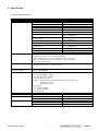
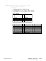
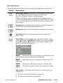
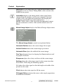
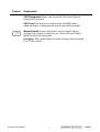
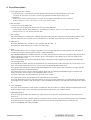
Service Manual ViewSonic VP2000s Model No. VLCDS26064-4W 20" Color TFT LCD Display (VP2000s_SM_892 Rev. 1a July 2004) ViewSonic 381 Brea Canyon Road, Walnut, California 91789 USA - (800) 888-8583 Copyright Copyright ¤ 2004 by ViewSonic Corporation. All rights reserved. No part of this publication may be reproduced, transmitted, transcribed, stored in a retrieval system, or translated into any language or computer language, in any form or by any means, electronic, mechanical, magnetic, optical, chemical, manual or otherwise, without the prior written permission of ViewSonic Corporation. Disclaimer ViewSonic makes no representations or warranties, either expressed or implied, with respect to the contents hereof and specifically disclaims any warranty of merchantability or fitness for any particular purpose. Further, ViewSonic reserves the right to revise this publication and to make changes from time to time in the contents hereof without obligation of ViewSonic to notify any person of such revision or changes. Trademarks Optiquest is a registered trademark of ViewSonic Corporation. ViewSonic is a registered trademark of ViewSonic Corporation. All other trademarks used within this document are the property of their respective owners. Revision History Revision 1a SM Editing Date 05/07/04 Documents Number DCN Number ECR Number 4530 Description of Changes A. Lu Initial Release Confidential - Do Not Copy ViewSonic Corporation i Editor VP2000s TABLE OF CONTENTS 1. Precautions and Safety Notices 1 2. Specification 2 3. Front Panel Function Control Description 12 4. Circuit Description 18 5. Adjusting Procedure 22 6. Trouble Shooting Flow Chart 25 7. Recommended Spare Parts List 29 8. Exploded Diagram And Spare Parts List 33 9. Block Diagram 38 10. Schematic Diagrams 39 11. PCB Layout Diagrams 45 Confidential - Do Not Copy ViewSonic Corporation ii VP2000s 1. Precautions and Safety Notices Prior to using this manual, please ensure that you have carefully followed all the procedures outlined in the user manual for this product. • Read all of these instructions. • Save these instructions for later use. • Follow all warnings and instructions marked on the product. • Do not use this product near water. • This display should be installed on a solid horizontal base. • When cleaning, use only a neutral detergent cleaner with a soft damp cloth. Do not spray with liquid or aerosol cleaners. • Do not expose this display to direct sunlight or heat. Hot air may cause damage to the cabinet and other parts. • Adequate ventilation must be maintained to ensure reliable and continued operation and to protect the display from overheating. Do not block ventilation slots and openings with objects or install the display in a place where ventilation may be hindered. • Do not install this display near a motor or transformer where strong magnetism is generated. Images on the display will become distorted and the color irregular. • Do not allow metal pieces or objects of any kind fall into the display from ventilation holes. Slots and openings in the cabinet and the back or bottom are provided for ventilation, to ensure reliable operation of the product and to protect it from overheating, those openings must not be blocked or covered. The openings should never be blocked by placing the product on a bed, sofa, rug, or other similar surface. This product should never be placed near or over a radiator or heat register. This product should not be placed in a built-in installation unless proper ventilation is provided. Confidential - Do Not Copy ViewSonic Corporation 1 VP2000s 2. Specification 2.1 Electrical Specification a. General specification: LCD panel suppliers: LCD panel specification: Input signals: Input connector: LG: LM201U03-A3./LM201U04-A3 a. Panel size: b. Driver element: c. Effective display area: d. Pixel pitch: e. Max. resolution: f. Display color: 20.1-inch (viewable). a - Si TFT active matrix. 408.0 (H) X 306.0 (V) mm. 0.255 (H) X 0.255 (V) mm. UXGA (1600X1200 pixels). 16.7M colors (R, G, B 8-bit data). 25 ms => LM201U03 g. Response time (ms)(typical): 16 ms => LM201U04 60% => LM201U03 h. Color Gamut: 72% => LM201U04 i. Color filter arrangement: R / G / B vertical stripe. j. Black light: Edge – light type with 6CCFLs. 350:1 => LM201U03 k. Contrast ratio: 400:1 => LM201U04 l. Luminance: 250cd/m2 (Typical). m. Luminance variation: 1.54 (MAX.). n. Viewing angle (CR >10): Horizontal: 176o, Vertical: 176o. a. Analog R / G / B (0.7Vp-p/75 ohm) Positive. b. Digital R /G / B DVI rev. 1.0 (TMDS single link) c. H & V separate Sync: TTL level; Polarity: Positive or Negative. d. H & V composite Sync: TTL level; Polarity: Positive or Negative. e. SOG (Sync level 0.3Vp-p). a. Analog D-sub 15pin x 1. b. Digital DVI-I 29 pin x 1. (Analog + Digital) Display data channel: DDC2B. (Appendix B) Signal frequency range: a. Horizontal: a-1. Analog: 30KHz ~ 95KHz. a-2. Digital: 30KHz ~ 92KHz. b. Vertical: 50Hz ~ 85*1Hz. Note: *1 The maximum vertical refresh rate of 1600x1200 as below: Analog input: 75 Hz. Digital input: 60 Hz. c. Pixel clock: c-1. Analog: 205MHz. c-2. Digital: 165MHz. d. Non-interlaced. 1600x1200. (UXGA) AC Input Range: AC 90 to 264V, 50/60Hz ± 3Hz, 1.5A. Less then 50Ap. For 115VAC. Less then 100Ap. For 230VAC. Less then 73W. On mode. Less then 5W. Active off mode. Less then 5W. DC power off. Resolution: Power supply: Inrush current Power Consumption: Confidential - Do Not Copy ViewSonic Corporation 2 VP2000s b. Physical specification. Overall dimension: Weight: Mechanical adjustment: Packaging: Accessories: a. Height: b. Width: c. Depth: a. Net weight: b. Gross weight: a. Tilt: b. Swivel: c. Height adjust: d. Pivot: a. Carton dimension: 480.55mm. 448.00mm. 266.65mm. 8.5kg. 11.2kg. +25o ~ -5o. ± 45o. 110mm. 90o. a. Height: 494mm. b. Width: 345mm. c. Depth: 560mm. Power cable 1.8m. User guide (English). CD ROM. Warranty card. HD15 - HD15 cable. DVI (D) – DVI (D) cable. Portrait Software CD c. Regulatory & Standard certification. Regulatory standards UL, cUL, FCC-B, CB, CE, ENERGY, NOM, TUV/GS, TUV-ERGO (covers ISO13406-2 & MPRII), TCO’03 (for VP201s), TCO99 (for VP201b), NEMKO, SEMKO, DEMKO, FIMKO, GOST-R, PCBC, VCCI, BSMI, CCC, (PSB), (C-TICK) 2.1.1 Picture size & position. a. Picture size. Input analog timing 1 ~ 25mode & DVI timing 1 ~ 22mode: (Appendix A) H-size: 408mm ± 1mm. V-size: 306mm ± 1mm. (Extra 640x350) b. Screen center. b-1. 1600x1200: H ± 1mm, V ± 1mm. b-2. Others mode: H ± 1.5mm, V ± 1mm. c. Picture position (refer to FIG.2). H-position:︱g3-g4︱≦ 1.5mm. V-position:︱g1-g2︱≦ 1.5mm. g1 306mm g3 g4 g2 408mm FIG. 2 2.1.2 Luminance test. Input1600x1200 / 60Hz & full white pattern at 100IRE, adjust brightness 100%, contrast 70%. Color temperature Y (Luminance) x, y value Analog DVI 9300°K x=0.283 , y=0.298 CCT(max) = 10250°K, CCT(min) = 8500°K > 140 cd/m2 > 140 cd/m2 6500°K x=0.313 , y=0.329 CCT(max) = 6950°K, CCT(min) = 6100°K > 180 cd/m2 > 180 cd/m2 5400°K x=0.335 , y=0.350 CCT(max) = 5915°K, CCT(min) = 4935°K > 180 cd/m2 > 180 cd/m2 5000°K x=0.346 , y=0.359 CCT(max) = 53500°K, CCT(min) = 4700°K > 180 cd/m2 > 180 cd/m2 Confidential - Do Not Copy ViewSonic Corporation 3 VP2000s 2.2. Adjustment control. 2.2.1 User control. - Power switch. - Function key. “1” : Function select button. “▼” : Adjustment button. “▲” : Adjustment button. “2” : Function select button. 2.2.2 OSD function. Auto Image Adjust* 2 Contrast/Brightness: Contrast, Brightness. Input Select: D-Sub, DVI-A, DVI-D. Color Adjust: 9300K, 6500K (default), 5400, 5000, User Color (R, G, B). Information: Resolution, Horizontal Frequency, Vertical Frequency, Model Number, Serial Number, Web Site. Manual Image Adjust: H. / V. Position* 2 (H. Position, V. Position), H. Size* 2 , Fine Tune* 2 , Sharpness* 3 , Scaling* 3 (Fill Screen, Fill Aspect Ratio* 4 , 1:1). Setup Menu: Language: English, French, German, Spanish, Italian, Finnish, Japanese, Traditional Chinese, Simplified Chinese. Resolution Notice: Enable, Disable. Input Priority: D-Sub, DVI-A, DVI-D, Auto Search. OSD Position: H. Position, V. Position. OSD Timeout: 5SEC, 15SEC, 30SEC, 60SEC OSD Background: On, Off. Memory Recall Note: * 2 These functions are not available in Digital mode; the setting is shaded and can't be selected. When auto tuning, the image should not be blanking. 3 * These functions are not available in 1600x1200 mode, the setting is shaded and can't be selected. * 4 When the input signal is 4:3, the “Fill Aspect ratio” function is the size same as “Fill Screen”. Confidential - Do Not Copy ViewSonic Corporation 4 VP2000s 2.3 Factory preset. 2.3.1 Special key (Hot key): Hold the following keys while powering on: [1]. Main Menu. [2]. Select next input. (Sequence: D-SUB → DVI-A → DVI-D) [UP] or [DOWN] arrow. To immediately activate Contrast menu. It should be change to Brightness OSD by push button [2]. [UP] + [DOWN] arrows. Recall Contrast or Brightness while in the Contrast or Brightness adjustment, or recall both of Contrast and Brightness when the OSD is not open. [1] + [2]. Toggle 720x400 and 640x400 mode when input 720x400 or 640x400 mode. [1] + [UP] + [DOWN]. White Balance. (keep press 5 seconds) (only used 1024x768/75Hz, 16 Grays) [1] + [DOWN]. Power Lock / Power Unlock. (keep press 10 seconds ) [1] + [UP]. OSD Lock / OSD Unlock (keep press 10 seconds ) DC-Power + [2] + [UP]. Copy EDID to E2PROM. DC-Power + [1]. Factory mode. (Burn in mode on) DC-Power + [2] + [DOWN]. Burn in mode on. DC-Power + [UP] + [DOWN]. Burn in mode off. DC-Power + [2]. All mode recall. AC-Power on. Enter ISP mode. 2.3.2 All mode recall setting: Contrast Brightness Color Temperature Scaling Sharpness Input Priority OSD H. Position OSD V. Position OSD Time Out OSD Background Resolution Notice 720x400/640x400 User color. Language. Clear burn in mode. Clear user mode table. 70%. 100%. 6500K. Full Screen. 0. Auto Search. 50%. 50%. 15 Sec On Enabled 720x400 50%. English. 2.3.3 Factory shipment setting: Main power switch: On. AC power button: Off. Others setting same as “All mode recall” setting. 2.4. Environmental conditions. 2.4.1 Temperature and humidity at operation : 0oC ~ 40oC. 20% ~ 90% RH (Non condensing). 2.4.2 Temperature and humidity at storage 2.4.3 Vibration test (packaged) : Vibration Frequency Acceleration Sweep time Test time 2.4.4 Drop test (packaged) 2.4.5 Altitude : Operating Non-operating : -20oC ~ 60oC. 5 ~ 90% RH (Non condensing). : 5 ~ 250Hz. : 1G. : 1 oct. / min. : 60 min per axis, total 3 axis. : 76.2cm height. 1 corner, 3 edges, 6 faces. : 0 ~ 3000 feet. : 0 ~ 12000 feet. Confidential - Do Not Copy ViewSonic Corporation 5 VP2000s Appendix A: Timing of inputs signals / nominal input level spec / Timing. Timing of input signals, Input level specification. A. Input signal: a. Analog R / G / B (0.7Vp-p/75 ohm) Positive. b. Digital R /G / B DVI rev. 1.0 (TMDS single link) c. H & V separate Sync: TTL level; Polarity: Positive or Negative. d. H & V composite Sync: TTL level; Polarity: Positive or Negative. B. Input signal connector: a. Analog video input: Pin Pin assignment 1 Red video 2 Green video 3 Blue video 4 GND 5 GND 6 Red video return 7 Green video return 8 Blue video return Pin5: For cable connection Pin 9 10 11 12 13 14 15 Pin assignment +5V for DDC GND GND DDC SDA H SYNC V SYNC DDC SCL detect. b. Digital video input: Pin Pin assignment 1 TMDS data 22 TMDS data 2+ 3 TMDS data 2 shield 4 NC 5 NC 6 DDC clock 7 DDC data 8 Analog V-SYNC C1 Analog R C4 Analog H-SYNC Pin15: For cable connection Pin Pin assignment 9 TMDS data 110 TMDS data 1+ 11 TMDS data 1 shield 12 NC 13 NC 14 +5V power 15 GND 16 Hot Plug Detect C2 Analog G C5 Analog Ground detect. Pin 17 18 19 20 21 22 23 24 C3 Pin assignment TMDS data 0TMDS data 0+ TMDS data 0 shield NC NC TMDS clock shield TMDS clock + TMDS clock Analog B Confidential - Do Not Copy ViewSonic Corporation 6 VP2000s C. Analog timing chart. Mode No. Horizontal Freq. 1 2 3 4 5 6 7 8 9 10 TEXT VESA MAC VESA VESA VESA TEXT VESA VESA VESA 640 x 640 x 640 x 640 x 640 x 640 x 720 x 800 x 800 x 800 x 350 480 480 480 480 480 400 600 600 600 35.156 31.468 31.469 35.000 37.861 37.500 43.269 31.469 37.879 48.077 Video clock Freq. 25.175 25.175 30.240 31.500 31.500 36.000 28.322 36.000 40.000 50.000 Mode Name Sync. Polarity + - - - - - - + + + H. total (Dots) 800 800 864 832 840 832 900 1024 1056 1040 H. sync. (Dots) 96 96 64 40 64 56 108 72 128 120 H. back porch (Dots) 48 48 96 128 120 80 54 128 88 64 H. active (Dots) 640 640 640 640 640 640 720 800 800 800 H. front porch (Dots) 16 16 64 24 16 56 18 24 40 56 Vertical Freq. (Hz) Sync. Polarity 70.087 59.940 66.667 72.809 75.000 85.008 70.087 56.250 60.317 72.188 - - - - - - + + + + V. total (Lines) 449 525 525 520 500 509 449 625 628 666 V. sync. (Lines) 2 2 3 3 3 3 2 2 4 6 V. back porch (Lines) 60 33 39 28 16 25 35 22 23 23 V. active (Lines) 350 480 480 480 480 480 400 600 600 600 V. front porch (Lines) 37 10 3 9 1 1 12 1 1 37 Mode No. Mode Name Horizontal Freq. (KHz) Video clock Freq. 11 12 13 14 15 16 17 18 19 20 VESA VESA MAC VESA VESA XGA VESA VESA VESA VESA 800 x 800 x 832 x 1024 x 1024 x 1024 x 1024 x 1024 x 1280 x 1280 x 600 600 624 768 768 768 768 768 1024 1024 46.875 53.674 49.727 48.363 56.476 58.099 60.023 68.677 63.981 79.976 49.500 56.250 57.285 65.000 75.000 78.084 78.750 94.500 108.00 135.00 Sync. Polarity + + - - - - + + + + 1056 1048 1152 1344 1328 1344 1312 1376 1688 1688 H. total (Dots) H. sync. (Dots) 80 64 64 136 136 136 96 96 112 144 H. back porch (Dots) 160 152 224 160 144 160 176 208 248 248 H. active (Dots) 800 800 832 1024 1024 1024 1024 1024 1280 1280 H. front porch (Dots) 16 32 32 24 24 24 16 48 48 16 Vertical Freq. (Hz) Sync. Polarity 75.000 85.061 74.553 60.004 70.069 72.082 75.029 84.997 60.020 75.025 + + - - - - + + + + V. total (Lines) 625 631 667 807 806 806 800 808 1066 1066 V. sync. (Lines) 3 3 3 6 6 6 3 3 3 3 V. back porch (Lines) 21 27 37 29 29 29 28 38 38 38 V. active (Lines) 600 600 624 768 768 768 768 768 1024 1024 V. front porch (Lines) 1 1 3 3 3 3 1 1 1 1 Confidential - Do Not Copy ViewSonic Corporation 7 VP2000s Mode No. Mode Name Horizontal Freq. (KHz) Video clock Freq. 21 22 23 24 25 VESA HDTV VESA VESA VESA 1280 x 1280 x 1600 x 1600 x 1600 x 1024 720 1200 1200 1200 91.146 45.000 75.000 87.500 93.750 26 27 28 29 30 157.50 74.250 162.00 189.00 202.500 Sync. Polarity + - + + + H. total (Dots) 1728 1650 2160 2160 2160 H. sync. (Dots) 160 40 192 192 192 H. back porch (Dots) 224 270 304 304 304 H. active (Dots) 1280 1280 1600 1600 1600 H. front porch (Dots) 64 60 64 64 64 Vertical Freq. (Hz) Sync. Polarity 85.024 60.000 60.000 70.000 75.000 + - + + + V. total (Lines) 1072 750 1250 1250 1250 V. sync. (Lines) 3 5 3 3 3 V. back porch (Lines) 44 20 46 46 46 V. active (Lines) 1024 720 1200 1200 1200 V. front porch (Lines) 1 5 1 1 1 Confidential - Do Not Copy ViewSonic Corporation 8 VP2000s D. Digital timing chart. Mode No. Horizontal Freq. 1 2 3 4 5 6 7 8 9 10 TEXT VGA VESA VESA VESA VESA TEXT VESA VESA VESA 640 x 640 x 640 x 640 x 640 x 640 x 720 x 800 x 800 x 800 x 350 400 480 480 480 480 400 600 600 600 35.156 31.468 31.468 31.469 37.861 37.500 43.269 31.469 37.879 48.077 Video clock Freq. 25.175 25.175 25.175 31.500 31.500 36.000 28.322 36.000 40.000 50.000 Mode Name Sync. Polarity + - - - - - - + + + H. total (Dots) 800 800 800 832 840 832 900 1024 1056 1040 H. sync. (Dots) 96 96 96 40 64 56 108 72 128 120 H. back porch (Dots) 48 48 48 128 120 80 54 128 88 64 H. active (Dots) 640 640 640 640 640 640 720 800 800 800 H. front porch (Dots) 16 16 16 24 16 56 18 24 40 56 Vertical Freq. (Hz) Sync. Polarity 70.087 70.087 59.940 72.809 75.000 85.008 70.087 56.250 60.317 72.188 - + - - - - + + + + V. total (Lines) 449 449 525 520 500 509 449 625 628 666 V. sync. (Lines) 2 2 2 3 3 3 2 2 4 6 V. back porch (Lines) 60 35 33 28 16 25 35 22 23 23 V. active (Lines) 350 400 480 480 480 480 400 600 600 600 V. front porch (Lines) 37 12 10 9 1 1 12 1 1 37 Mode No. Mode Name Horizontal Freq. (KHz) Video clock Freq. 11 12 13 14 15 16 17 18 19 20 VESA VESA VESA VESA XGA VESA VESA VESA VESA VESA 800 x 800 x 1024 x 1024 x 1024 x 1024 x 1024 x 1280 x 1280 x 1280 x 600 600 768 768 768 768 768 1024 1024 1024 46.875 53.674 48.363 56.476 58.099 60.023 68.677 63.981 79.976 91.146 49.500 56.250 65.000 75.000 78.084 78.750 94.500 108.00 135.00 157.50 Sync. Polarity + + - - - + + + + + H. total (Dots) 1056 1048 1344 1328 1344 1312 1376 1688 1688 1728 H. sync. (Dots) 80 64 136 136 136 96 96 112 144 160 H. back porch (Dots) 160 152 160 144 160 176 208 248 248 224 H. active (Dots) 800 800 1024 1024 1024 1024 1024 1280 1280 1280 H. front porch (Dots) 16 32 24 24 24 16 48 48 16 64 Vertical Freq. (Hz) Sync. Polarity 75.000 85.061 60.004 70.069 72.082 75.029 84.997 60.020 75.025 85.024 + + - - - + + + + + V. total (Lines) 625 631 807 806 806 800 808 1066 1066 1072 V. sync. (Lines) 3 3 6 6 6 3 3 3 3 3 V. back porch (Lines) 21 27 29 29 29 28 38 38 38 44 V. active (Lines) 600 600 768 768 768 768 768 1024 1024 1024 V. front porch (Lines) 1 1 3 3 3 1 1 1 1 1 Confidential - Do Not Copy ViewSonic Corporation 9 VP2000s Mode No. Mode Name Horizontal Freq. (KHz) Video clock Freq. 21 22 HDTV VESA 1280 x 1600 x 720 1200 45.000 75.000 23 24 25 26 27 28 29 30 74.250 162.00 Sync. Polarity - + H. total (Dots) 1650 2160 H. sync. (Dots) 40 192 H. back porch (Dots) 270 304 H. active (Dots) 1280 1600 H. front porch (Dots) 60 64 Vertical Freq. (Hz) Sync. Polarity 60.000 60.000 - + V. total (Lines) 750 1250 V. sync. (Lines) 5 3 V. back porch (Lines) 20 46 V. active (Lines) 720 1200 V. front porch (Lines) 5 1 Confidential - Do Not Copy ViewSonic Corporation 10 VP2000s E. 128 bytes of EDID code for VP2000s analog 0 1 2 3 4 5 6 7 8 9 0 00 FF FF FF FF FF FF 00 5A 63 10 1A 23 01 01 01 01 01 0E 01 03 20 0E 29 1F 78 2A 60 E5 A3 57 4B 30 9C 25 11 50 54 BF EF 80 A9 40 40 A9 4F 81 80 81 40 71 4F 61 59 50 45 59 31 59 48 3F 40 30 62 B0 60 32 40 40 C0 13 00 98 32 11 00 70 00 1E 00 00 00 FF 00 50 39 34 80 30 34 30 31 90 00 00 00 FD 00 32 55 1E 5F 15 30 30 30 30 31 0A 100 00 0A 20 20 20 20 20 20 00 00 110 00 FC 00 56 50 32 30 30 30 73 120 0A 20 20 20 20 20 00 26 F. 128 bytes of EDID code for VP2000s digital 0 1 2 3 4 5 6 7 8 9 0 00 FF FF FF FF FF FF 00 5A 63 10 1A 23 01 01 01 01 01 0E 01 03 20 80 29 1F 78 2A 60 E5 A3 57 4B 30 9C 25 11 50 54 BF EF 80 A9 40 40 81 80 81 40 71 4F 61 59 45 59 50 31 59 31 0A 48 3F 40 30 62 B0 60 32 40 40 C0 13 00 98 32 11 00 70 00 1E 00 00 00 FF 00 50 39 34 80 30 90 00 00 00 FD 00 32 55 1E 5C 11 100 00 0A 20 20 20 20 20 20 00 00 110 00 FC 00 56 50 32 30 30 30 73 120 0A 20 20 20 20 20 00 78 34 30 31 30 30 30 30 31 0A Confidential - Do Not Copy ViewSonic Corporation 11 VP2000s 3. Front Panel Function Control Description Adjusting the Screen Image Use the buttons on the front control panel to display and adjust the OnView® controls which display on the screen. The OnView controls are explained at the top of the next page. Main Menu with OnView controls Front Control Panel shown below in detail Scrolls through menu options and adjusts the displayed control. Also a shortcut to display the Contrast adjustment control screen. Displays the control screen for the highlighted control. Also toggles between two controls on some screens. Also a shortcut to toggle analog and digital connection. Displays the Main Menu or exits the control screen and saves adjustments. Power light Green = ON Orange = Power Saving Power On/Off Confidential - Do Not Copy ViewSonic Corporation 12 VP2000s Do the following to adjust the screen image: 1 To display the Main Menu, press button [1]. NOTE: All OnView menus and adjustment screens disappear automatically after about 30 seconds. 2 To select a control you want to adjust, press ▲ or ▼ to scroll up or down the Main Menu. 3 After the control is selected, press button [2]. 4 To adjust the control, press the up ▲ or down ▼ buttons. 5 To save the adjustments and exit the menu, press button [1] twice. The following tips may help you optimize your display: • Adjust your computer's graphic card so that it outputs a video signal 1600 x 1200 @ 60 Hz to the LCD display. (Look for instructions on “changing the refresh rate” in your graphic card's user guide.) • If necessary, make small adjustments using H POSITION and V POSITION until the screen image is completely visible. (The black border around the edge of the screen should barely touch the illuminated “active area” of the LCD display.) Confidential - Do Not Copy ViewSonic Corporation 13 VP2000s Main Menu Controls Adjust the menu items shown below by using the up ▲ and down ▼ buttons. Control Explanation Auto Image Adjust automatically sizes, centers, and fine tunes the video signal to eliminate waviness and distortion. Press the [2] button to obtain a sharper image. NOTE: Auto Image Adjust works with most common video cards. If this function does not work on your LCD display, then lower the video refresh rate to 60 Hz and set the resolution to its pre-set value. Contrast adjusts the difference between the image background (black level) and the foreground (white level). Brightness adjusts background black level of the screen image. Input Select allows you to toggle between an analog and a digital signal. Color Adjust provides several color adjustment modes: preset color temperatures and RGB which allows you to adjust red (R), green (G), and blue (B) separately. The factory setting for this product is 6500K (6500 Kelvin). 9300K — Adds blue to the screen image for cooler white (used in most office settings with fluorescent lighting). 6500K — Adds red to the screen image for warmer white and richer red. 5400K — Adds green to the screen image for a darker color. 5000K — Adds blue and green to the screen image for a darker color. User Color — Individual adjustments for red (R), green (G), and blue (B). 1 2 To select color (R, G or B) press button [2]. To adjust selected color, press ▲ or ▼. Confidential - Do Not Copy ViewSonic Corporation 14 VP2000s Control Explanation Important: If you select RECALL from the Main Menu when the product is set to a Preset Timing Mode, colors return to the 6500K factory preset. Information displays the timing mode (video signal input) coming from the graphics card in your computer. See your graphic card’s user guide for instructions on changing the resolution and refresh rate (vertical frequency). NOTE: VESA 1600 x 1200 @ 60 Hz (recommended) means that the resolution is 1600 x 1200 and the refresh rate is 60 Hertz. Manual Image Adjust displays the Manual Image Adjust menu. The Manual Image Adjust controls are explained below: Horizontal Position moves the screen image left or right. Vertical Position moves the screen image up or down. Horizontal Size adjusts the width of the screen image. Fine Tune sharpens focus by aligning the illuminated text and/ or graphic characters. Sharpness adjusts the clarity and focus of the screen image. Scaling adjusts the video input signal to the screen size other than 1600 x 1200 using the following options. 1:1 adjusts the video signal so that the height and width of the picture are the same. Fill all adjusts the video signal to fill the screen. Fill Aspect Ratio maintains the correct video signal proportions for different resolutions. Confidential - Do Not Copy ViewSonic Corporation 15 VP2000s Control Explanation Setup Menu displays the menu shown below. The Setup Menu controls are explained below: Language allows you to choose the language used in the menus and control screens. Resolution Notice displays the Resolution Notice menu shown below. Resolution Notice advises the optimal resolution to use. Input Priority If multiple computers will be connected to the display, this function can be used to select which computer has priority Depending on the selected Input Priority, the display will do a one time detection for available inputs when first powered on. OSD Position allows you to move the on-screen display menus and control screens. OSD Timeout sets the length of time an on-screen display screen is displayed. For example, with a “15 second” setting, if a control is not pushed within 15 seconds, the display screen disappears. Confidential - Do Not Copy ViewSonic Corporation 16 VP2000s Control Explanation OSD Background allows you to turn the On-Screen-Display background on or off. OSD Pivot This function is used to rotate the OSD menu, when the display is changed from Landscape to Portrait mode. Memory Recall returns adjustments to the original factory settings if the display is operating in a factory Preset Timing Mode listed in this user guide. Exception: This control does not affect changes made with the User Color control. Confidential - Do Not Copy ViewSonic Corporation 17 VP2000s 4. Circuit Description 1. Power supply (DC/DC Converter): 1.1 IC251 BA9741F is a two-channel switching regulator controller that uses PWM method. For DC to DC conversion for step-down. It converts a 12V DC into regulated and stable output voltage of 5V. 1.2 Regulator: IC252, IC253, IC254, IC255 function is to convert 5V into regulated and stable O/P of 3.3V and 2.5V. IC252 converts 5V to 2.5V; converts 5V to 3.3V; IC253, IC254, IC255. 2. DDC data select: 2.1 IC601 is save D-SUB DDC data. 2.2 IC606 save DVI-A analog DDC data, IC605 save DVI-D digit DDC data. IC604 is triple 2 channel analog multiplexes / de-multiplexes, IC604 pin 10 & 11 is “Lo” select IC605 DDC data, IC604 pin 10 & 11 is “Hi” select IC606 DDC data. 3. ADC (Analog): The IC608 AD9888 is a complete 8-bit, 205MSPS monolithic analog interface optimized for capturing RGB graphics signal from PC. The IC608 have two input source (D-SUB & DVI-A), the input source control by I2C from IC401 scaler. 4. TMDS (DVI): The IC609 THC63DV161 is a TMDS receiver compliant with DVI Rev. 1.0. The IC609 turn on/off control by pin 2 “DPD” from IC401 scaler. 5. Scaler: The PW166B image processor is a highly integrated “system-on-a-chip” that interfaces analog, digital, and video inputs in virtually any format to a digital projection system or multimedia display. Any embedded SDRAM frame buffer and memory controller perform frame rate conversion. Computer images from VGA to UXGA at almost any refresh rate can be resized to fit on a fixed-frequency target display device with any resolution up to UXGA with full 24-bit color. The PW166B includes advanced second generation image scaling that provides completely programmable, horizontal and vertical image scaling. The PW166B also includes advanced second-generation sync decoding which provides full support for a wide variety of sync types. This includes interlaced, progressive, sync-on-green, and TMDS DE (Data Enable) only. An integrated OSD controller provides bit-mapped based OSD with 16 colors from a 64K color palette. The OSD controller supports transparent and translucent functions. The Graphics Port (GPort) captures computer graphics inputs with very high input bandwidth through an external IC608 Analog-To-Digital converter (ADC) or IC609 digital interface receiver. The DPort is designed to be connected directly to LVDS (IC501, IC502). The output timing is fully programmable and is independent of the input timing. An on-chip 80x86 microprocessor with custom features for image processing applications is provided. Built in port interrupts, General Purpose I/O (GPIO), UART, IR Decoders, Timers and PWM Generator provide a full featured hardware base to build on. 6. LVDS Transmitter: The IC501, IC502 transmitter converts 28 bits of CMOS/TTL data into LVDS (Low Voltage Differential Signaling) data stream. A phase-locked transmit clock is transmitted in parallel with the data streams over a fifth LVDS link. 7. USB HUB Controller: IC951 is a high speed USB HUB controller, this single-chip device incorporates one upstream and four downstream USB transceivers. IC951 CY7C65640 includes interface signals for external port power switches. The power switching and over-current detection of downstream ports is managed by control pins connected to an external power switch device by IC952 & IC953. IC954 is an EEPROM VID & PID configured. Confidential - Do Not Copy ViewSonic Corporation 18 VP2000s Confidential - Do Not Copy ViewSonic Corporation 19 VP2000s ViewSonic Corporation ! ! Confidential - Do Not Copy 20 VP2000s ViewSonic Corporation ! ! Confidential - Do Not Copy 21 VP2000s 5. Adjusting Procedure A. General. 1. All specification must be met over line voltage range of 90VAC to 264VAC 50Hz / 60Hz, unless otherwise specified. 2. Operating temperature range is 0oC to 40oC with a relative humidity of 10% or less to 80%. 3. The monitor must be operational in a usable state within 30 minutes after turn-on. 4. All signal levels are measured assuming termination at the monitor’s input jacks or in its characteristic impedance. 5. All controls must have excess range (no control may be left at an end stop when proper alignment is completed). 6. The monitor is not required to meet specs during the following but must tolerate, without damage to the LCD or circuits, any sequence or combination of power on and off, signal on and off, erratic, wrong frequency or noisy inputs while at any possible unplugging of power or signal, settings of user accessible controls likewise, the monitor should survive extended periods of operation with line voltage reduced below the specified minimum. 7. An isolation transformer should be used when performing alignment and tests, Portions of the power supply board are hot ground, The remaining boards are cold ground. 8. Ambient condition: 8.1 Illumination: 150 ~ 260 lux. 8.2 Environmental noise: Less than 60dB. 8.3 Interference of EMI: No excessive electric or magnetic fileds. o 8.4 Temperature: 24 ± 2 C. 8.5 Humidity: 65 ± 20%. ViewSonic Corporation ! ! Confidential - Do Not Copy 22 VP2000s B. Instrument alignment. 1. Adjustment procedure. Input D-SUB Push "2" Input DVI-A Push "2" Input DVI-D Input 1024x768 / 75Hz 16 Grays pattern Push "1 + DC power" 3 seconds Push "1 + DC power" 3 seconds Push "DOWN + 2 + DC power" 3 seconds Select "Color Adjust" to adjust "9300K", "6500K" "5400K", "5000K" Select "Color Adjust" to adjust "9300K", "6500K" "5400K", "5000K" Push "1" Exit adjust OSD Push "1" Exit adjust OSD Push "1 + DC power" 3 second Select "RGB Reset" function Push "2 + DC power" to close factory mode Input 1600x1200 / 60 Hz Full white pattern Push "1 + DC power" 3 seconds Select "Color Adjust" to adjust "9300K", "6500K" "5400K", "5000K" Push "1" Exit adjust OSD ViewSonic Corporation ! ! Confidential - Do Not Copy 23 VP2000s 2. Video alignment. 1.1 Preset condition. 1.1.1 Setting the contrast to 70%, brightness to 100%. 1.1.2 Input 1024x768 / 75Hz, 16 gray pattern (input level 100IRE 0.7Vp-p), then press “RGB RESET”. 9300K / 6500K / 5400K / 5000K, R G B sub-contrast preset as below: 9300K 6500K 5400K Analog DVI Analog DVI Analog DVI R sub-contrast 128 128 128 128 128 128 G sub-contrast 128 128 128 128 128 128 B sub-contrast 128 128 128 128 128 128 5000K Analog DVI 128 128 128 128 128 128 1.2 9300K alignment: 1.2.1 Input 1024x768 / 75Hz & full white pattern at 100IRE. 1.2.2 Adjust R, G, and B sub-contrast to meet following chromaticity spec: 9300K → x = 0.283 ± 0.005, y = 0.298 ± 0.005, Y > 150cd/m2 (Both analog & DVI). 1.3 6500K alignment: 1.3.1 Input 1024x768 / 75Hz & full white pattern at 100IRE. 1.3.2 Adjust R, G and B sub-contrast to meet following chromaticity spec: 6500°K → x = 0.313 ±0.005, y = 0.329 ± 0.005, Y > 200cd/m2 (Both analog & DVI). 1.4 5400K alignment: 1.4.1 Input 1024x768 / 75Hz & full white pattern at 100IRE. 1.4.2 Adjust R, G, and B sub-brightness to meet following chromaticity spec: 5400K → x = 0.335 ± 0.005, y = 0.350 ± 0.005, Y > 180cd/m2 (Both analog & DVI). 1.5 5000K alignment: 1.5.1 Input 1024x768 / 75Hz & full white pattern at 100IRE. 1.5.2 Adjust R, G and B sub-contrast to meet following chromaticity spec: 5000°K → x = 0.346 ±0.005, y = 0.359 ± 0.005, Y > 180cd/m2 (Both analog & DVI). 1.6 64grays & 16grays pattern check: 1.6.1 Input 1600x1200 / 60Hz & 64 grays pattern at 100IRE, adjust brightness 100%, and contrast 70%. 1.6.2 9300K / 6500K / 5400K / 5000K, the 64 grays can 2steps saturation. 1.6.3 Input 1600x1200 / 60Hz & 16 grays pattern at 100IRE, adjust brightness 100%, and contrast 100%. 1.6.4 9300K / 6500K / 5400K / 5000K, the 16 grays only had 3 grays can saturation. ViewSonic Corporation ! ! Confidential - Do Not Copy 24 VP2000s 6. Trouble Shooting Flow Chart 1. No power. Check that CN251 pin1, 2 are approximately 18V. Yes No Failure point. Check that FB251, FB252 are 18V. 1. Power board failure. 2. Disconnected between CN251 and power board. No Failure point. FB251, FB252 failure. Yes Check that C263 positive is at 5V. Check that C261 positive is at 5V (for VP201). No Failure point. 1. Q258, D252 failure. 2. Q255, D251 failure (for VP201). 3. IC251 failure. Yes Check: 1. IC252 is O/P 2.5V. 2. IC253 is O/P 3.3V. 3. IC254 is O/P 3.3V. 4. IC255 is O/P 3.3V. ViewSonic Corporation ! ! Confidential - Do Not Copy 25 VP2000s 2. No display on screen (Screen is black, LED is off). AC power on and DC power on No picture LED is off Yes Yes Check that the voltage level of CN251 is approximately 18V Check that C263 positive is at 5V No Yes No Check CN252 pin1 is 18V, pin5 is 5V Yes Inverter failure ViewSonic Corporation IC251 failure Power board failure No 1. Check IC401 B3 pin. 2. Check Q259. ! ! Confidential - Do Not Copy 26 VP2000s 3. No display on screen (LED is green). Is the backlight lit ? Yes No Check that the cable is fully connected between the inverter and interface board. Check that the cable is fully connected to CN501. Failure point. No Yes No Failure point. The cable is disconnected. The cable is disconnected. Check IC501, IC502. Yes No Failure point. 1. IC501, IC502 failure. 2. IC401 failure. Check CN252 pin1 is 12V, pin5 is 5V Yes Check Q263 pin4 is low voltage. Yes No No Q263 failure Inverter failure. 1. Check IC401 B3 pin. 2. Check Q259. Yes Check Q263 pin5, 6, 7, 8 is about: 1. 18V for VP211. 2. 5V for VP201. ViewSonic Corporation No Q263 failure ! ! Confidential - Do Not Copy 27 VP2000s 4. Show “No signal” on screen. Check that signal level of R604, R605, R606, R619, R620, R621. No Yes Failure point. No Check the Hsync and Vsync. 1. IC608 failure. 2. Signal cable is disconnected. 5. Keypad cannot work. Check that the cable is fully connected between the interface board and key board Yes Failure point. No Failure point. 1. IC405 pin2, 3, 4, 5, 6 failure. 2. TACT switch failure. The cable is disconnected. ViewSonic Corporation ! ! Confidential - Do Not Copy 28 VP2000s 7. Recommended Spare Parts List VP2000s-1 RSPL Rev 1a (Initial) Item ViewSonic P/N 1 B-PS-0204-0060 2 E-L-0407-1587 3 M-SW-0815-0224 4 A-VC-0101-0390 5 M-FC-0809-0838 6 A-PC-0106-0150 7 M-SCW-0824-0772 8 M-SCW-0824-0690 9 M-SCW-0824-0775 10 M-SCW-0824-0776 11 M-SCW-0824-0777 12 M-SCW-0824-0784 13 M-SCW-0824-0732 14 M-SCW-0824-0413 15 M-MS-0808-8040 16 M-LB-0813-0785 17 M-MS-0808-8556 18 M-LB-0813-0978 19 M-LB-0813-1049 20 M-LB-0813-0900 21 M-LB-0813-0714 22 M-LB-0813-1050 23 M-MS-0808-8624 24 M-MS-0808-0724 25 M-MS-0808-7463 26 M-MS-0808-7810 27 M-MS-0808-4975 28 M-MS-0808-0918 29 M-MS-0808-1679 30 M-MS-0808-1680 31 M-MS-0808-8557 32 M-MS-0808-2276 33 M-MS-0808-2631 34 PL-PD-0714-0140 35 M-MS-0808-0016 36 M-MS-0808-8627 37 PL-NB-0707-1075 38 M-CV-0830-2458 39 M-CV-0830-2602 40 C-FP-0301-1050 41 C-BS-0303-0554 42 M-MS-0808-8630 43 M-MS-0808-8631 44 M-MS-0808-8637 45 M-MS-0808-8638 46 M-MS-0808-8640 47 M-MS-0808-8642 48 M-MS-0808-2660 49 M-MS-0808-2662 50 M-MS-0808-8643 51 M-MS-0808-8646 52 P-FM-0602-0591 53 P-FM-0602-0592 54 M-MS-0808-8762 55 M-MS-0808-2667 56 M-MS-0808-2671 57 M-MS-0808-3190 58 M-MS-0808-2672 59 M-MS-0808-2815 60 P-BX-0601-1023 61 M-MS-0808-5135 62 M-MS-0808-7820 63 PL-SP-0723-0002 64 A-CD-VP2000S 65 M-MS-0808-3151 66 M-BK-0805-0112 67 B-SB-0221-0529 ViewSonic Corporation Ref. P/N 993027602 2921021404 3000725101 3080427000 3080516300 3090107600 3100130800 3105051501 3105123700 3105221000 3105225300 3109010700 3109010900 3109011400 3110250000 3200158900 3200649100 3200787200 3201979200 3202011000 3202310700 3209218400 3211030700 3220161733 3220501600 3220605633 3221101500 3221903300 3222201300 3222400310 3240055600 3240160801 3240946900 3240970900 3241127301 3241127400 3360627100 3361207400 3368222700 3368311100 3368991402 3460150100 3460150200 3461226402 3461226500 3463000700 3463002000 3470903500 3470903600 3472851200 3472855100 3500105500 3500105600 3500937501 3500939901 3500943900 3510449200 3510449300 3511208300 3512268400 3520082400 3520130500 3520142700 3532086300 3532086400 3790195400 4900505280 Description POWER 90-264VAC 18V 3.33A COMPUTER CORE BEAD 40*6.5*10 W5H+TAPE SWITCH MEMBRANCE PET 99.5*9 VP181CABLE D-SUB/D-SUB L1800 BLK OD7.5 CABLE FFC 30P P1.0 L340 T1 AC POWER CORD L=1800 BLACK UL/CSA SCREW M M3*0.5*8 FPH C S20C ZN BLK SCREW M #4-40*7 HEXH #4-40*3 S18C SCREW M M4*0.7*10 FF C S18C ZN BLK SCREW M M3*0.5*6 FF C S18C ZN SCREW M M3*0.5*4 FF C S18C ZN SCREW T M3*0.5*7 PAN C S+P S20C ZN SCREW T M3*0.5*4 BIND C S18C ZN YE SCREW T M3*0.5*6 BIND C S18C ZN YE WASHER SPRING SWRT LABEL STICKER OD10 WHT HI-POT NAME PLATE VSC 3-BIRD LOGO AL 11.0 LABEL BAR CODE 124*82 LABEL ID 100*50 VSC VP2000S LABEL SERIES PANEL 42*11 T0.05 LABEL HV WARNING 100*25 LABEL POP STICKER 89*89 VSC MYLAR FILM 430*330 T.1 L20CBR05ACA TAPE W=20 #3800A NITTO TAPE W=30 #10 3M TAPE W=45 #7290 NITTO TAPE W=76 PP47 914M 4P TAPE PE W=50 VIEWSONIC SECURITY TAPE AL FOIL W=25 #80023 CATERON TAPE W=16 #897 3M CONDUCTIVE TAPE AL W50*L55 1120 SPONGE EVA 5.8*5 T.5 BLK RUBBER SILICON 12*12 T5 RUBBER PAD 22*4 T3 BLK INSULATOR PC 130*118.5 T.5 INSULATOR PC 231*13 T.5 POWER KNOB POM 901U 5140 S8LFB1LS COVER VESA ABS 41S8LBB1LS CABINET ASSY L20CBR05DDB S0LRA1AT F/B ASSY L20CBR05CDB S0LFA1AT STAND ASSY L20CBR05ADB S8LBB1LS SE BRACKET PANEL SIDE-R SECC 325*30*2 BRACKET PANEL SIDE-L SECC 325*30*2 SHIELD CAN IF SPTH 298.9*150.1*41. SHIELD CAN INV SPTH 210*73.8*18 T. CONDUCTIVE AL 15*25 T0.06 CONDUCTIVE AL 50*100 T.06 HANDLE PE 162*40.5 T1.5 BOTTOM NO5 HANDLE PE 209*18 T1.8 TOP NO501 CONDUCTIVE SPONGE 30*8.5*10 CONDUCTIVE SPONGE 10*10*12 END BLOCK-TOP EPS L20CBW05AAW END BLOCK-BOTTOM EPS L20CBW05AAW PE BAG 300*200*0.06T PE BAG 740*580*.06T CLEAR PE BAG 75*75*160L T.1 CAP PAPER 1130*1390*120 CAP PAPER 1130*700*120 ANGLE PAPER 2070*55*55 T5 CARTON 552*337*489 VSC VP2000S PE FILM t=0.02mm W=500 DRYER 15G 80*60 PLASTIC STRIP W=12 T.5 BLACK CD-ROM VSC A-CD-VP2000S MANUAL PACKING ASSY VSC VP2000S PANEL BKT L20CBR05DDB DC-AC INVERTER 20" LG PANEL ! ! Confidential - Do Not Copy 29 Q'ty 1 1 1 1 1 1 4 4 4 6 6 1 4 4 4 1 1 1 1 1 1 1 1 0.15 0.29 0.128 0.8 1.028 0.18 0.03 1 1 2 1 1 1 1 1 1 1 1 1 1 1 1 1 2 1 1 1 1 1 1 1 1 2 0.032 0.063 0.375 1 0.04 2 1 1 1 1 1 VP2000s VP2000s-1 BOM Rev 1a (Initial) Item ViewSonic P/N 1 B-PS-0204-0021 2 E-L-0407-1587 3 M-SW-0815-0224 4 A-VC-0101-0390 5 M-FC-0809-0838 6 M-SCW-0824-0772 7 M-SCW-0824-0690 8 M-SCW-0824-0775 9 M-SCW-0824-0776 10 M-SCW-0824-0777 11 M-SCW-0824-0784 12 M-SCW-0824-0732 13 M-SCW-0824-0413 14 M-MS-0808-8040 15 M-LB-0813-0785 16 M-MS-0808-8556 17 M-LB-0813-0978 18 M-LB-0813-1049 19 M-LB-0813-0900 20 M-LB-0813-0714 21 M-LB-0813-1050 22 M-MS-0808-8624 23 M-MS-0808-0724 24 M-MS-0808-7463 25 M-MS-0808-7810 26 M-MS-0808-4975 27 M-MS-0808-0918 28 M-MS-0808-1679 29 M-MS-0808-1680 30 M-MS-0808-8557 31 M-MS-0808-2276 32 M-MS-0808-2631 33 PL-PD-0714-0140 34 M-MS-0808-0016 35 M-MS-0808-8627 36 PL-NB-0707-1075 37 M-CV-0830-2458 38 M-CV-0830-2602 39 C-FP-0301-1050 40 C-BS-0303-0554 41 M-MS-0808-8630 42 M-MS-0808-8631 43 M-MS-0808-8637 44 M-MS-0808-8638 45 M-MS-0808-8640 46 M-MS-0808-8642 47 M-MS-0808-2660 48 M-MS-0808-2662 49 M-MS-0808-8643 50 M-MS-0808-8646 51 P-FM-0602-0591 52 P-FM-0602-0592 53 M-MS-0808-8762 54 M-MS-0808-2667 55 M-MS-0808-2671 56 M-MS-0808-3190 57 M-MS-0808-2672 58 M-MS-0808-2815 59 P-BX-0601-1023 60 M-MS-0808-5135 61 M-MS-0808-7820 62 PL-SP-0723-0002 63 M-MS-0808-3275 64 M-MS-0808-3374 65 A-CD-VP2000S 66 M-MS-0808-3151 67 M-BK-0805-0112 68 B-SB-0221-0529 69 M-LCD-0826-0205 70 #N/A 71 #N/A 72 #N/A 73 #N/A 74 E-R-0405-7041 75 E-R-0405-7049 76 E-R-0405-6684 77 78 E-R-0405-6684 E-R-0405-7054 ViewSonic Corporation Ref. P/N 993027602 2921021404 3000725101 3080427000 3080516300 3100130800 3105051501 3105123700 3105221000 3105225300 3109010700 3109010900 3109011400 3110250000 3200158900 3200649100 3200787200 3201979200 3202011000 3202310700 3209218400 3211030700 3220161733 3220501600 3220605633 3221101500 3221903300 3222201300 3222400310 3240055600 3240160801 3240946900 3240970900 3241127301 3241127400 3360627100 3361207400 3368222700 3368311100 3368991402 3460150100 3460150200 3461226402 3461226500 3463000700 3463002000 3470903500 3470903600 3472851200 3472855100 3500105500 3500105600 3500937501 3500939901 3500943900 3510449200 3510449300 3511208300 3512268400 3520082400 3520130500 3520142700 3524009601 3524009701 3532086300 3532086400 3790195400 4900505280 5052000450 5600110257 341052300 341059300 341070300 343000300 343100300 343101100 Description POWER 90-264VAC 18V 3.33A COMPUTER CORE BEAD 40*6.5*10 W5H+TAPE SWITCH MEMBRANCE PET 99.5*9 VP181CABLE D-SUB/D-SUB L1800 BLK OD7.5 CABLE FFC 30P P1.0 L340 T1 SCREW M M3*0.5*8 FPH C S20C ZN BLK SCREW M #4-40*7 HEXH #4-40*3 S18C SCREW M M4*0.7*10 FF C S18C ZN BLK SCREW M M3*0.5*6 FF C S18C ZN SCREW M M3*0.5*4 FF C S18C ZN SCREW T M3*0.5*7 PAN C S+P S20C ZN SCREW T M3*0.5*4 BIND C S18C ZN YE SCREW T M3*0.5*6 BIND C S18C ZN YE WASHER SPRING SWRT LABEL STICKER OD10 WHT HI-POT NAME PLATE VSC 3-BIRD LOGO AL 11.0 LABEL BAR CODE 124*82 LABEL ID 100*50 VSC VP2000S LABEL SERIES PANEL 42*11 T0.05 LABEL HV WARNING 100*25 LABEL POP STICKER 89*89 VSC MYLAR FILM 430*330 T.1 L20CBR05ACA TAPE W=20 #3800A NITTO TAPE W=30 #10 3M TAPE W=45 #7290 NITTO TAPE W=76 PP47 914M 4P TAPE PE W=50 VIEWSONIC SECURITY TAPE AL FOIL W=25 #80023 CATERON TAPE W=16 #897 3M CONDUCTIVE TAPE AL W50*L55 1120 SPONGE EVA 5.8*5 T.5 BLK RUBBER SILICON 12*12 T5 RUBBER PAD 22*4 T3 BLK INSULATOR PC 130*118.5 T.5 INSULATOR PC 231*13 T.5 POWER KNOB POM 901U 5140 S8LFB1LS COVER VESA ABS 41S8LBB1LS CABINET ASSY L20CBR05DDB S0LRA1AT F/B ASSY L20CBR05CDB S0LFA1AT STAND ASSY L20CBR05ADB S8LBB1LS SE BRACKET PANEL SIDE-R SECC 325*30*2 BRACKET PANEL SIDE-L SECC 325*30*2 SHIELD CAN IF SPTH 298.9*150.1*41. SHIELD CAN INV SPTH 210*73.8*18 T. CONDUCTIVE AL 15*25 T0.06 CONDUCTIVE AL 50*100 T.06 HANDLE PE 162*40.5 T1.5 BOTTOM NO5 HANDLE PE 209*18 T1.8 TOP NO501 CONDUCTIVE SPONGE 30*8.5*10 CONDUCTIVE SPONGE 10*10*12 END BLOCK-TOP EPS L20CBW05AAW END BLOCK-BOTTOM EPS L20CBW05AAW PE BAG 300*200*0.06T PE BAG 740*580*.06T CLEAR PE BAG 75*75*160L T.1 CAP PAPER 1130*1390*120 CAP PAPER 1130*700*120 ANGLE PAPER 2070*55*55 T5 CARTON 552*337*489 VSC VP2000S PE FILM t=0.02mm W=500 DRYER 15G 80*60 PLASTIC STRIP W=12 T.5 BLACK PALLET FUMIGATE 1120*1380*120 PALLET FUMIGATE 1120*690*120 CD-ROM VSC A-CD-VP2000S MANUAL PACKING ASSY VSC VP2000S OTHER ASSY PANEL BKT L20CBR05DDB DC-AC INVERTER 20" LG PANEL LCD 20.1" TFT PANEL UXGA LCD I/F BD ASSY L20CBR 05DDB RES CH 1/10W 4.7K F 0603 RES CH 1/10W 10K F 0603 RES CH 1/10W 30K F 0603 RES CH 1/10W ZERO J 0603 RES CH 1/10W 10 J 0603 RES CH 1/8W 100 J 0805 343101300 343102300 RES CH 1/10W 100 J 0603 RES CH 1/10W 1K J 0603 ! ! Location R260,R261 R273 R272 C256,R412,R417,R431 R266 R265 R438,R439,R440,R441,R442,R608,R609,R618 ,R619,R620,R621,R622,R630,R633,R643,R65 0,R651,R652 R419,R422 Confidential - Do Not Copy 30 Q'ty 1 1 1 1 1 4 4 4 6 6 1 4 4 4 1 1 1 1 1 1 1 1 0.15 0.29 0.128 0.8 1.028 0.18 0.03 1 1 2 1 1 1 1 1 1 1 1 1 1 1 1 1 2 1 1 1 1 1 1 1 1 2 0.032 0.063 0.375 1 0.04 2 1 0.032 0.063 1 1 1 1 1 1 2 1 1 4 1 1 18 2 VP2000s Item ViewSonic P/N 79 E-R-0405-6685 Ref. P/N 343103100 Description RES CH 1/8W 10K J 0805 80 81 82 E-R-0405-6685 #N/A #N/A 343103300 343151300 343220100 RES CH 1/10W 10K J 0603 RES CH 1/10W 150 J 0603 RES CH 1/8W 22 J 0805 83 84 85 86 87 E-R-0405-7042 E-R-0405-6687 #N/A #N/A #N/A 343220300 343222300 343223300 343270300 343332100 RES CH 1/10W 22 J 0603 RES CH 1/10W 2.2K J 0603 RES CH 1/10W 22K J 0603 RES CH 1/10W 27 J 0603 RES CH 1/8W 3.3K J 0805 88 89 90 91 92 E-R-0405-7057 E-R-0405-7120 E-R-0405-7043 E-R-0405-6690 E-R-0405-7033 343332300 343391300 343392300 343470300 343471300 RES CH 1/10W 3.3K J 0603 RES CH 1/10W 390 J 0603 RES CH 1/10W 3.9K J 0603 RES CH 1/10W 47 J 0603 RES CH 1/10W 470 J 0603 93 94 95 96 97 98 99 E-R-0405-7031 #N/A #N/A E-R-0405-6691 #N/A E-R-0405-6693 #N/A 343472300 343561100 343561300 343562300 343681300 343750100 343821100 RES CH 1/10W 4.7K J 0603 RES CH 1/8W 560 J 0805 RES CH 1/10W 560 J 0603 RES CH 1/10W 5.6K J 0603 RES CH 1/10W 680 J 0603 RES CH 1/8W 75 J 0805 RES CH 1/8W 820 J 0805 100 101 #N/A #N/A 619900305 730060412 RES ARRAY 1/16W 47 J 8P4R 1206 CRYSTAL 14.318MHZ 30PPM 30PF 49US 102 103 104 105 106 107 108 109 110 111 112 113 114 115 #N/A #N/A #N/A E-C-0404-4854 #N/A #N/A #N/A #N/A #N/A E-C-0404-4878 E-C-0404-4876 #N/A #N/A #N/A 920990061 149024701233 149101021533 149122201208 149122211333 149144701433 149144711533 149161081103 1511512000 1511514000 1512445000 1512448000 1517654000 1517657000 VOLTAGE SUPPRESSOR 5V 10P M 0603 CAP AL CP 6.3V 47U M 5*5.4 CAP AL CP 10V 1KU M 10*10 CAP AL CP 16V 22U M 5*5.5 CAP AL CP 16V 220U M 6.3*7.7 CAP AL CP 25V 47U M 8*5.4 CAP AL CP 25V 470U M 10*10 CAP AL CP 50V 1U M 4*5.7 CAP MC CP 50V 18P J C0G 0603 CAP MC CP 50V 22P J C0G 0603 CAP MC CP 50V 1KP K X7R 0603 CAP MC CP 50V 3.9KP K X7R 0603 CAP MC CP 50V .01U Z Y5V 0603 CAP MC CP 50V .047U Z Y5V 0603 116 117 118 E-C-0404-4497 #N/A #N/A 1517658000 1517690000 1557667100 CAP MC CP 50V .1U Z Y5V 0603 CAP MC CP 50V .039U Z Y5V 0603 CAP MC CP 25V 1U Z Y5V 0805 119 120 121 122 123 124 125 126 127 128 129 130 131 132 133 134 135 #N/A #N/A #N/A #N/A #N/A E-D-0403-2135 E-Q-0402-1087 E-Q-0402-7019 #N/A E-Q-0402-7018 #N/A E-Q-0402-1552 E-IC-0401-2925 #N/A #N/A #N/A #N/A 15A7691100 202351580023 203812520836 203812540236 203812670236 204520700307 210522000405 210522000505 211522000205 211522000405 243502600010 243601100031 2500058010 2500058037 2500082637 2500088136 2500224136 CAP MC CP 10V 10U Z Y5V 0805 DIO SBD 5A 40V DO-201AD DIO ZEN 0.5W 3.32-3.53V LLDS(MINIM DIO ZEN 0.5W 4.94-5.20V LLDS(MINIM DIO ZEN 0.5W 16.82-17.7V LLDS(MINI DIO SW 0.215A 75V SOT-23 TR 40V 0.2A SOT-23 100-300 TR 40V 0.6A SOT-23 80 TR -40V -0.2A SOT-23 100-300 TR -40V -0.6A SOT-23 100 FET -55V -11A 0.175ohm TO-252AA FET -30V -8.0A 0.02OHM LL SO-8 IC REGU LDO 0.8A 3.3V SOT-223 IC REGU LDO 0.8A 3.3V SOT-223 IC REGU LDO 2.5V 5A TO-252 IC VOL DETECTOR 4.4V SOT-23 IC REGU 3.3V 0.4A SOT-89 ViewSonic Corporation ! ! Location R613,R627 R256,R257,R262,R274,R275,R278,R281,R406 ,R443,R444,R445,R446,R447,R450,R614,R61 5,R628,R629,R635 R604,R605,R606 R271 Q'ty 2 R423,R424,R425,R426,R646,R647,R648,R649 R277,R611,R612,R623,R631 R283,R285 R430 R421 R282,R284,R403,R404,R407,R408,R409,R410 ,R413,R415,R427,R428,R453,R634 R636 R254 R607,R610,R616,R617 R401,R402 R276,R448,R449,R637,R638,R639,R640,R641 ,R642,R653 R405 R451,R452 R255 R436,R437 R601,R602,R603,R624,R625,R626 R267 8 5 2 1 1 RP401,RP402,RP403,RP404,RP405,RP406,RP 407,RP408,RP409,RP410,RP411,RP412,RP60 1,RP602,RP603,RP604,RP605,RP606,RP607, RP608,RP609,RP610,RP611,RP612,RP613,RP 614,RP615,RP616,RP617,RP618,RP619,RP62 0,RP621,RP622,RP623,RP624,RP625 X401 VA401,VA402,VA403,VA404,VA405,VA605, VA606,VA607,VA608,VA613,VA617 C269,C272,C630 C263 C659 C266,C280 C275,C279,C428 C260,C262 C264,C273 C401,C402 C403,C605,C606,C609,C614 C255,C258,C601,C613 C633 C254 C602,C603,C604,C610,C611,C612 C251,C259,C265,C267,C268,C270,C271,C276 ,C277,C278,C404,C405,C406,C407,C408,C40 9,C410,C411,C412,C413,C414,C415,C416,C4 17,C418,C419,C420,C421,C422,C423,C424,C 425,C426,C427,C501,C502,C503,C504,C505, C506,C507,C508,C509,C510,C607,C608,C615 ,C616,C617,C618,C619,C620,C621,C622,C62 3,C624,C625,C626,C627,C628,C629,C631,C6 32,C635,C636,C637,C638,C639,C640,C641,C 642,C643,C644,C645,C646,C647,C648,C649, C650,C651,C658,C664,C665,C675 C634 C253,C274 C281,C282,C283,C284,C285,C286,C287,C676 ,C677,C678,C679 D252 D401,D603,D604,D605,D606,D609 D602,D608 D253 D601,D607 Q252,Q259,Q260,Q261,Q262 Q256 Q401,Q402 Q257 Q258 Q263 IC254 IC253,IC254 IC252 IC402 IC255 Confidential - Do Not Copy 31 19 3 1 14 1 1 4 2 10 1 2 1 2 6 1 37 1 11 3 1 1 2 3 2 2 2 5 4 1 1 6 84 1 2 11 1 6 2 1 2 5 1 2 1 1 1 1 1 1 1 1 VP2000s Item 136 137 138 139 140 141 142 143 144 145 146 147 148 149 150 151 152 ViewSonic P/N #N/A #N/A #N/A #N/A #N/A #N/A #N/A #N/A #N/A #N/A #N/A E-IC-0401-2942 E-IC-0401-1834 E-IC-0401-3984 #N/A #N/A #N/A Ref. P/N 2510019129 2510406024 2530108343 2530147512 2530207213 2530208043 2540170221 2600062607 2600071007 2600088009 2610015107 2610049742 2610188137 2641109302 2816721510 2816727480 2921095612 Description IC PWM SOP-16P IC SW-CAP(10UF) VOLT CONVERTER SOIC TRIPLE VIDEO BUFFER G=+1 TSSOPIC PANEL-LINK RECEIVER TQFP-100P IC IMAGE PROCESSOR PBGA-256B IC 205MSPS ANALOG INTERFACE MQFP-1 IC LVDS I/F TSSOP-56P IC OCTAL BUFFER 3-S SSOP-20P IC ANALOG CMOS SO-14PIN IC HEX INVERTER SOIC-14 IC 2 CHANNEL ANALOGUE SO16 IC CMOS 2K EEPROM SOIC-8P IC EEPROM 256*8BIT SOIC-8PIN IC 2610501923+5015013601 ASSY CHOKE SMT 10uH K CHOKE SMT 22uH M 3.6A BEAD CH 100MHZ 60 OHM 0.3A 0603 153 154 155 156 157 158 159 160 161 162 163 164 #N/A #N/A #N/A #N/A #N/A #N/A #N/A #N/A #N/A M-LB-0813-0913 M-LB-0813-0914 M-LB-0813-0915 2921113212 2970036605 3000750026 3070337534 3071400334 3075308757 3075316357 3075415766 3075415866 3202005900 3202009100 3202215900 BEAD CH 100MHZ 120 OHM 4A 1206 PWB M0 L4 FR-4 170*119 (I/F BD) L2 SWITCH ROLL BALL 4P P2.54 HEADER NY66 94V0 7P P2.0 R BROWN HEADER NY66 94V0 4P P2.5 R CONN D-SUB 15P R/A PC99 W/O SCREW CONN DVI-I 29P P1.905 R CONN FFC/FPC BOTTOM 30P P1.0 SMT CONN FFC/FPC BOTTOM 8P P1.0 SMT LABEL SERIAL 42*11 SONY LABEL REISTRATION 40*16 LABEL MCU 11*11 POLYESTER 50# ViewSonic Corporation ! ! Location IC251 IC612 IC610 IC609 IC401 IC608 IC501,IC502 IC405 IC603 IC602,IC607 IC604 IC601,IC605,IC606 IC403 IC404 L254 L253 FB601 FB251,FB252,FB255,FB257,FB258,FB259,FB 260,FB261,FB262,FB401,FB602 CN252 CN251 CN601 CN602 CN501 CN402 FOR STICK ON I/F BD STICK ON I/F BD STICK ON IC301 Confidential - Do Not Copy 32 Q'ty 1 1 1 1 1 1 2 1 1 2 1 3 1 1 1 1 1 11 1 1 1 1 1 1 1 1 1 1 0.125 VP2000s 8. Exploded Diagram And Spare Parts List ViewSonic Corporation ! ! Confidential - Do Not Copy 33 VP2000s ViewSonic Corporation ! ! Confidential - Do Not Copy 34 VP2000s ViewSonic Corporation ! ! Confidential - Do Not Copy 35 VP2000s ViewSonic Corporation ! ! Confidential - Do Not Copy 36 VP2000s VP2000s-1 Exploded Part List VP2000s-1 Exploded Part List Rev 1a (Initial) Item ViewSonic P/N ReferenceNumber 3200649100 1 M-MS-0808-8556 3361092600 2 C-FP-0301-1024 3360506800 3 M-MS-0808-8559 3360627100 4 PL-NB-0707-1075 3460150100 5 M-MS-0808-8630 3460150200 M-MS-0808-8631 3461226500 6 M-MS-0808-8638 3241127301 7 M-MS-0808-0016 3241127400 8 M-MS-0808-8627 3360254400 9 C-BC-0302-0627 3460146300 10 M-MS-0808-8563 3361207500 11 M-CV-0830-2459 3361208000 12 M-CV-0830-2464 3460151002 13 M-MS-0808-9854 3460150703 14 M-MS-0808-9855 3460151102 15 M-MS-0808-9856 3460150902 16 M-MS-0808-9857 3460150801 17 M-MS-0808-8633 3240957000 18 PL-PD-0714-0100 3240968900 19 PL-PD-0714-0101 3360245300 20 M-CV-0830-2472 3470308700 21 M-WR-0828-0739 3461752001 22 M-MS-0808-8572 3361207700 23 M-CV-0830-2461 3361207400 24 M-CV-0830-2458 3361207900 25 M-CV-0830-2463 3200651100 26 M-MS-0808-8758 3361207800 27 M-CV-0830-2462 3460146100 28 M-MS-0808-8561 3461226402 29 M-MS-0808-8637 3460190600 30 M-BK-0805-0113 3000725100 31 B-KB-0207-0034 3105221000 32 M-SCW-0824-0776 3109010700 33 M-SCW-0824-0784 3105123700 34 M-SCW-0824-0775 3109011400 35 M-SCW-0824-0413 3100130800 36 M-SCW-0824-0772 3109010900 37 M-SCW-0824-0732 3105221000 38 M-SCW-0824-0776 3105225300 39 M-SCW-0824-0777 3105034400 40 M-SCW-0824-0773 3105127100 41 M-SCW-0824-0781 3105229400 42 M-SCW-0824-0778 3105280200 43 M-SCW-0824-0782 3105280400 44 M-SCW-0824-0783 3105280400 45 M-SCW-0824-0783 3109017700 46 M-SCW-0824-0779 3109017700 47 M-SCW-0824-0779 3109019100 48 M-SCW-0824-0780 3109019100 49 M-SCW-0824-0780 4900505280 50 B-SB-0221-0529 5600110257 51 B-IF-0222-0063 993027602 52 B-PS-0204-0060 ViewSonic Corporation Description NAME PLATE ABS 94HB VIEWSONIC 82.83*34.9 F/B ABS LED LENS ABS 1865-12 S8LRB1LS POWER KNOB POM M270 MIDNIGHT GRAY BRACKET PANEL SIDE-R SECC 325*30*25 T.8 BRACKET PANEL SIDE-L SECC 325*30*25 T.8 SHIELD CAN INV SPTH 202*83.3*38.1 T.3 INSULATOR PC 130*118.5 T.5 INSULATOR PC 231*13 T.5 CABINET BACK ABS 41 S0LRA1AT VP2000S BRACKET KEYLOCK SECC 20.4*16.45*4.9 T.6 COVER STAND FRONT ABS COVER HINGE2 ABS BRACKET BASE3 SECC OD139.01*163.3 T2 BRACKET BASE2 SECC OD139*163.3 T2 BRACKET BASE1 SECC 164*139 T2 BRACKET BASE FOOT2 SECC 159.8*29.1 T2 BRACKET BASE2 FOOT1 SECC OD182*59.9 T2 RUBBER PAD OD20 T4 BLACK RUBBER PAD 20*20 T3 BLK COVER STAND BOTTOM WIRE SADDLE NYLON66 COLOR41 HINGE SECC 312.5*51.82 L18JBW05ABB COVER STAND REAR ABS COVER VESA ABS 41 COVER HINGE1 ABS NAME PLATE VIEWSONIC ABS 82.83*34.98 COVER BASE ABS S8LBB1LS BRACKET VESA SECC 110*20 T1 SHIELD CAN IF SPTH 299*150*41.5 T.3 BRACKET PANEL SECC 433.4*216.3*42 T.8 LG SWITCH MEMBRANE PET 100*9 VP181-2 SCREW M M3*0.5*6 FF C S18C ZN SCREW T M3*0.5*7 PAN C S+P S20 SCREW M M4*0.7*10 FF C S18C ZN SCREW T M3*0.5*6 BIND C S18C ZN SCREW M M3*0.5*8 FPH C SC20C ZN SCREW T M3*0.5*4 BIND C S18C ZN SCREW M M3*0.5*6 FF C S18C ZN SCREW M M3*0.5*4 FF C S18C ZN SCREW M M3*0.5*6 FLAT C S20C Z SCREW M M4*0.7*12 FF C S18C ZN SCREW M M3*0.5*10 FF C S18C ZN SCREW M M3*0.5*4 FF C S18C ZN SCREW M M3*0.5*4 FLAT C S20C Z SCREW M M3*0.5*4 FLAT C S20C Z SCREW T M3*2.7*7.5 FF C S18C Z SCREW T M3*2.7*7.5 FF C S18C Z SCREW T M3*2.7*7.2 FLAT C S18C SCREW T M3*2.7*7.2 FLAT C S18C DC-AC INVERTER 20" LG PANEL LCD I/F BD ASSY POWER 90-264VAC 18V 3.33A ! ! Confidential - Do Not Copy 37 QTY 1 1 1 1 1 1 1 1 1 1 1 1 1 1 1 1 1 1 3 1 1 3 1 1 1 1 1 1 1 1 1 1 6 1 4 4 4 4 2 2 6 4 1 2 8 4 2 2 4 2 1 1 1 VP2000s 9. Block Diagram Confidential - Do Not Copy ViewSonic Corporation 38 VP2000s 10. Schematic Diagrams Confidential - Do Not Copy ViewSonic Corporation 39 VP2000s Confidential - Do Not Copy ViewSonic Corporation 40 VP2000s Confidential - Do Not Copy ViewSonic Corporation 41 VP2000s Confidential - Do Not Copy ViewSonic Corporation 42 VP2000s Confidential - Do Not Copy ViewSonic Corporation 43 VP2000s Confidential - Do Not Copy ViewSonic Corporation 44 VP2000s 11. PCB Layout Diagrams ViewSonic Corporation ! ! Confidential - Do Not Copy 45 VP2000s ViewSonic Corporation ! ! Confidential - Do Not Copy 46 VP2000s ViewSonic Corporation ! ! Confidential - Do Not Copy 47 VP2000s *Readers Response* Dear Readers: Thank you in advance for your feedback on our Service Manual,which allows continuous improvement of our products. We would appreciate your completion of the Assessment Matrix below, for return to ViewSonic Corporation. Assessment A.What do you think about the content after reading VP2000s Service Manual? U nit Ex cellent Fair G ood Bad 1. Precautions And Safety Notices 2. Specification 3. Front Panel Function Control Description 4. Circuit Description 5. Adjusting Procedure 6. Trouble Shooting Flow Chart 7. Recommended Spare Parts List 8. Exploded Diagram and Spare Parts List 9. Block Diagram 10. Schematic Diagrams 11. PCB Layout Diagrams B.Are you satisfied with the VP2000s service manual? It em Ex cellent G ood Fair Bad 1. Service Manual Content 2. Service Manual Layout 3. The form and listing C.Do you have any other opinion or suggestion about this service manual? Readers basic data: Name: Title: Company: Add.: Fax: Tel: E-mail: After completing this form, please return it to ViewSonic Quality Assurance in the USA at facsimile 1-909-839-7943. You may also e-mail any suggestions to the Director, Quality Systems & Processes ([email protected]) Confidential - Do Not Copy ViewSonic Corporation 48 VP2000s