1
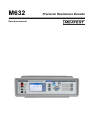
M632
Operation manual
Precision Resistance Decade
M632 Precision Resistance Decade
MEATEST
Content
FIGURES ............................................................................................................................................................... 4
TABLES ................................................................................................................................................................. 4
1.
BASIC INFORMATION............................................................................................................................. 5
2.
PREPARATION FOR USE ........................................................................................................................ 5
2.1.
2.2.
2.3.
2.4.
3.
INSPECTING PACKAGE CONTENTS, SELECTING THE INSTALLATION LOCATION ........................................ 5
POWER ON ............................................................................................................................................. 5
WARM-UP TIME ..................................................................................................................................... 6
SAFETY PRECAUTIONS ........................................................................................................................... 6
DESCRIPTION............................................................................................................................................ 7
3.1.
3.2.
4.
FRONT PANEL ........................................................................................................................................ 7
REAR PANEL .......................................................................................................................................... 9
OPERATION ............................................................................................................................................. 10
4.1.
4.2.
4.3.
4.4.
4.5.
4.6.
CONNECTION AND DISCONNECTION OF OUTPUT TERMINALS ................................................................ 10
WIRES CONNECTION ............................................................................................................................ 10
SETTING THE FUNCTION ....................................................................................................................... 10
SETTING THE VALUE OF OUTPUT SIGNAL.............................................................................................. 17
SETUP MENU ....................................................................................................................................... 18
CALIBRATION MODE ............................................................................................................................ 20
5.
PERFORMANCE VERIFICATION TEST ............................................................................................ 23
6.
REMOTE CONTROL............................................................................................................................... 24
6.1.
6.2.
6.3.
6.4.
6.5.
6.6.
6.7.
6.8.
6.9.
6.10.
6.11.
6.12.
7.
RS232 INTERFACE .............................................................................................................................. 24
GPIB INTERFACE (OPTION) ................................................................................................................. 25
LAN INTERFACE (OPTION) .................................................................................................................. 26
USB INTERFACE (OPTION)................................................................................................................... 27
COMMAND SYNTAX ............................................................................................................................. 28
SCPI COMMAND TREE ........................................................................................................................ 29
STANDARD STATUS DATA STRUCTURES ............................................................................................. 31
SCPI STANDARD COMMANDS ............................................................................................................. 33
SCPI COMMANDS ............................................................................................................................... 37
SCPI ERROR CODES ............................................................................................................................ 59
COMPATIBLE COMMANDS ................................................................................................................... 60
DEMO PROGRAM ................................................................................................................................. 62
MAINTENANCE....................................................................................................................................... 63
7.1.
7.2.
FUSE REPLACING ................................................................................................................................. 63
EXTERNAL SURFACE CLEANING ........................................................................................................... 63
8.
MODULE 19” (VERSION M632-VXX1X) ............................................................................................. 63
9.
TECHNICAL DATA ................................................................................................................................. 64
ORDERING INFORMATION – OPTIONS..................................................................................................... 66
3
Version 18
Operation manual
MEATEST
M632 Precision Resistance Decade
Figures
Figure 1 Starting Screen............................................................................................................. 6
Figure 2 Front panel ................................................................................................................... 7
Figure 3 Display......................................................................................................................... 7
Figure 4 Rear panel .................................................................................................................... 9
Figure 5 Resistance screen ....................................................................................................... 10
Figure 6 Platinum screen.......................................................................................................... 11
Figure 7 Nickel screen ............................................................................................................. 11
Figure 8 User function screen .................................................................................................. 12
Figure 9 User function list ....................................................................................................... 12
Figure 10 New user function.................................................................................................... 13
Figure 11 User function point editing ...................................................................................... 13
Figure 12 User function edit .................................................................................................... 14
Figure 13 Timing screen .......................................................................................................... 14
Figure 14 Time sequence list ................................................................................................... 15
Figure 15 New sequence .......................................................................................................... 15
Figure 16 Timing sequence point editing................................................................................. 16
Figure 17 Timing sequence edit............................................................................................... 16
Figure 18 Numeric value entry................................................................................................. 17
Figure 19 Setup menu .............................................................................................................. 18
Figure 20 Password entry......................................................................................................... 20
Figure 21 Calibration point screen........................................................................................... 22
Figure 22 RS232 9 pin D-SUB MALE connector ................................................................... 24
Figure 23 IEEE488 connector .................................................................................................. 25
Figure 24 LAN connection 1.................................................................................................... 26
Figure 25 LAN connection 2.................................................................................................... 26
Figure 26 USB connector......................................................................................................... 27
Figure 27 Status register overview........................................................................................... 31
Figure 28 Module 19" rack, front panel ................................................................................... 63
Tables
Table 1 M632 Calibration points ............................................................................................. 21
Table 2 Verification - allowed deviations................................................................................ 23
Table 3 RS232 cable connection.............................................................................................. 25
Table 4 OUTPut command structure ....................................................................................... 40
Table 5 Keyboard codes........................................................................................................... 56
Table 6 SCPI error codes ......................................................................................................... 59
Table 7 M632 Resistance accuracy.......................................................................................... 65
Table 8 M632 Pt simulation accuracy...................................................................................... 65
Table 9 M632 Ni simulation accuracy ..................................................................................... 65
Table 10 M632 Frequency response ........................................................................................ 65
Operation manual
4
M632 Precision Resistance Decade
MEATEST
1. Basic information
Programmable resistance decade M632 is suitable for automated simulation of different
resistance sensors (temperature, pressure, position, force …). Internal design eliminates “zero
resistance effect” which is typical for most resistance decades.
Resistance value is created via appropriate combination of physical resistors. Decade is
equipped with built-in function of direct simulation of most frequent temperature Pt and Ni sensors.
Low thermal voltage relays and stable resistors are used as main parts of the decade. Actual set values
are displayed high resolution TFT display. M632 is sophisticated instrument with its own recalibration procedure. The procedure enables to correct any deviation in resistance without any
mechanical adjusting.
Instrument is especially suitable for automatic testing procedures. RS232 line (optionally
IEEE488, USB and Ethernet bus) is used for connecting decade to the computer.
2. Preparation for use
2.1.
Inspecting package contents, selecting the installation location
Basic package includes the following items:
•
•
•
•
•
Resistance decade M632
RS232 cable
CD with demo program
User’s manual
Test report
The instrument must be powered by 230/115 V – 50/60 Hz mains. Before powering on the
instruments, place it on a level surface. If the instrument was stored out of range of reference
temperatures, let it stabilize for one hour.
2.2.
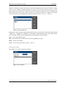
Power on
•
Before connecting the instrument to the mains, check the position of the mains voltage selector
located at the rear panel.
•
Plug one end of the power cord into the connector located at the rear panel and connect the other
end of the power cord into a wall outlet.
5
Operation manual
MEATEST
•
M632 Precision Resistance Decade
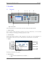
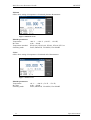
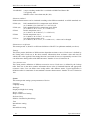
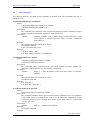
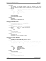
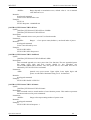
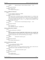
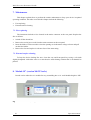
Switch on the mains switch located at the rear panel. Display is lit.
Figure 1 Starting Screen
•
The instrument performs internal hardware checks for app. 5 seconds.
•
After the tests conclude, the instrument resets to its reference state, i.e. the following
parameters are set:
Function
Set value
Output terminals
Resistance
100.00 Ω
OFF
2.3. Warm-up time
The instrument works after it is switched on and the initial checks complete. Specified
parameters are only guaranteed after the instrument warms up for 10 minutes.
2.4. Safety precautions
The instrument has been designed according to EN 61010-1:2011. Safety is ensured by the
design and by the use of specific component types.
The manufacturer is not liable for the damage caused by modification of the construction or
replacement of parts with non-original ones.
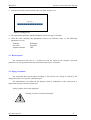
Safety symbols used on the equipment
Warning, reference to the documentation
Operation manual
6
M632 Precision Resistance Decade
MEATEST
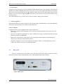
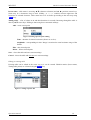
3. Description
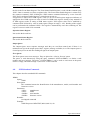
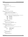
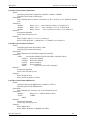
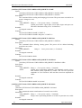
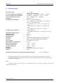
3.1.
Front panel
1
3
2
4
5
6
8
7
Figure 2 Front panel
On the front panel there are located all main control keys, display and output terminals.
1
Output terminals
Four wire output terminals. Measuring (evaluation) circuit can be connected by 2, 3 or 4 wires. Both
sides (red and grey) are floating up to 500Vpk against the case (PE).
2
Ground terminal
Central groud terminal (protective earth) connected to the metal case of the instrument. It is
recommended to connect it to the “grey” output terminals if connected meter is not grounded.
3
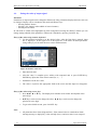
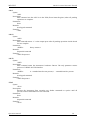
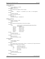
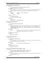
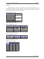
Display
A
D1
B1
B1
B2
B1
B1
B3
B1
C1
D2
D3
B1
C2
B1
C3
B1
D4
B1
Figure 3 Display
The display is divided into four sections:
A. Information line
•
•
7
Selected function (RESISTANCE, PLATINUM, …)
Time
Operation manual
MEATEST
M632 Precision Resistance Decade
B. Main area
This section displays the set-up values of generated signals and the data related to the decade box
status. The section includes the following types of data:
1. Auxiliary parameters
This section displays auxiliary parameters of actually selected function:
• Temperature standard (PT385, PT3916, …)
• Switching mode (FAST, VIA OPEN, …)
• R0 resistance
2. Main value
There is displayed main value of selected function with the unit. There is displayed also
actual position of cursor ▼▲ if the parameter is in edit mode. Position of cursor can be
changed using keys ◄, ► and parameter can be changed using keys ▲,▼.
3. Output state
There is displayed resistance value connected to the output terminals.
C. Specification
This section displays specification and limits relating to the main value:
1. Specification
This section displays specification of the main value.
2. Maximum voltage
This section displays maximum allowed voltage for the main value.
3. Maximum current
This section displays maximum allowed current for the main value.
D. Softkey labels
The functions of these keys change during operation (depends on selected function and actual
display mode).
4
Softkeys
There are four keys next to the display with variable function. The functions of these keys change
during operation (depends on selected function and actual display mode).
5
OPER (Operate key)
OPER key connects / disconnects selected value to the output terminals. Connected output terminals
are indicated by the lit LED in the key.
6
SHORT (Short key)
Active SHORT key (LED in the key is ON) replaces the main value with the short circuit. Also the
short circuit must be connected to the output terminals by the OPER key.
Operation manual
8
M632 Precision Resistance Decade
7
MEATEST
Cursor keys
Using these keys, the cursor can be controlled within allowed limits on the display. The keyboard
includes two buttons (◄, ►) which allow the cursor to be set to the required position at the display.
The cursor can be moved to the left or right. Numeric values can be set in some control modes as well.
In these cases, the buttons marked (▲,▼) allow the user to increase or decrease the number at the
cursor position.
The central SELECT key is used to select value you want to change (like TAB key).
8
Numeric keyboard
The keyboard allows the entry of numeric values on the display. ENTER button is used to confirm the
selection. CANCEL button can be used to cancel the entry.
Colors on display
Common rules are used for applied color of labels and values.
- Red color is applied, when displayed value is measured by the instrument. This color isn’t use in
all versions.
-
Blue color is applied for parameters or values, which can be set-up or modified directly from front
panel keyboard or via Main menu.
-
Black color is used for fix values, labels, notes, parameters which cannot be modified and for
other fix text with general information purpose.
-
Meaning of softkeys is shown in the right part of display. If there is no description next to the
softkey, the softkey is not active in selected function.
3.2.
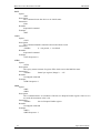
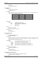
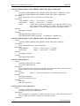
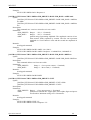
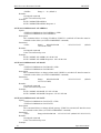
Rear panel
There are located power cord socket, power line fuse, power line voltage selector 115/230V,
interface connectors RS232 and optionaly LAN, USB and IEEE488 on the rear panel.
Figure 4 Rear panel
9
Operation manual
MEATEST
M632 Precision Resistance Decade
4. Operation
4.1.
Connection and disconnection of output terminals
Set value is connected (disconnected) to the output terminals after pressing OPER key.
Connected output terminals are indicated by the lit LED in the key.
Disconnected output terminals can be used for “Open terminals” simulation. “Short circuit” is
simulated after pressing SHORT key. Active SHORT key (LED in the key is ON) replaces the main
value with the short circuit. Also the short circuit must be connected to the output terminals by the
OPER key.
4.2.
Wires connection
Output resistance is available on R output terminals. Available is 2, 3 and 4-wire connection.
Both sides (red and grey) are floating up to 500Vpk against the case (PE).
Ground terminal is connected to the metal case and to the protective earth (PE).
4.3.
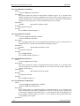
Setting the function
Function can be changed after pressing „Function“ softkey. New function is selected using
cursor keys ▲,▼ or display softkeys. Selection must be confirmed by pressing SELECT key or „OK“
softkey.
Device supports following functions:
Resistance
Offers direct setting of exact resistance value.
Figure 5 Resistance screen
Editable parameters:
Resistance value:
Switching mode:
Operation manual
1 Ω … 1.2 MΩ
FAST, SMOOTH, VIA OPEN, VIA SHORT
10
M632 Precision Resistance Decade
MEATEST
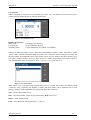
Platinum
Offers direct setting of temperature of simulated platinum thermometer.
Figure 6 Platinum screen
Editable parameters:
Temperature:
R0 value:
Temperature standard:
Switching mode:
-200 °C … +850 °C (-328 °F … 1562 °F)
10 Ω … 20 kΩ
PT385 (68), PT385 (90), PT3916, PT3926, PT User
FAST, SMOOTH, VIA OPEN, VIA SHORT
Nickel
Offers direct setting of temperature of simulated nickel thermometer.
Figure 7 Nickel screen
Editable parameters:
Temperature:
R0 value:
Switching mode:
11
-60 °C … +300 °C (-76 °F … 572 °F)
10 Ω … 20 kΩ
FAST, SMOOTH, VIA OPEN, VIA SHORT
Operation manual
MEATEST
M632 Precision Resistance Decade
User function
Offers simulation of conversion curve defined by a table. User can define more conversion curves.
Values between defined points are linearly interpolated.
Figure 8 User function screen
Editable parameters:
Main value:
User function:
Switching mode:
according to the function
curves defined by the user
FAST, SMOOTH, VIA OPEN, VIA SHORT
Function is defined by table of user values and corresponding resistance values. This table is called
„Curve“ and is editable. Maximum number of tables is 10 with each table having up to 8 values but
the fewer tables are defined the more values within can be set. For instance one table can have up to
120 values, 3 tables can have up to 36 values and so on. Tables can be defined via remote control as
well. Manual table setup can be done in Menu → Device → User function curve:
Figure 9 User function list
Menu shows a list of all previously defined tables (curves). Screen above shows two tables named
„CURVE1“ and „CURVE2“ but number of tables and their names can be different due to local
settings. Softkeys on the right hand side of the panel have these functions:
New – create a plain table (curve).
Edit – edit selected table. Table can be selected using ▲,▼ cursor keys.
Delete – delete selected table.
Close – close the menu and return to Menu → Device.
Operation manual
12
M632 Precision Resistance Decade
MEATEST
Creating a new table
Pressing the New softkey opens this submenu:
Figure 10 New user function
Curve name – table name is set using ▲,▼ (character selection) and ◄, ► (position) cursor keys.
Name may be 8 characters long at most. Softkey „A <-> a“ switches between uppercase and
lowercase of selected character. Table name has to be set before proceeding to the next step using
SELECT key.
Unit – user function unit abbreviation is set in the same way as table name only it can be just up to
two characters long. Unit abbreviation has to be set before proceeding to the next step using the
SELECT key.
Lookup table – a place where you define user function using values in Ω. Table must contain at least
two “user function value → Ω value” points so that a slope of the function can be calculated. Range in
user function mode is given by actual resistance range of the decade. Browsing through the table is
done by ▲,▼ cursor keys. Editing is done using these contextual softkeys:
Add – create a new point.
Figure 11 User function point editing
Amplitude – user function value in user units. Press the SELECT key to proceed.
Resistance – corresponding Ω value. Range is restricted to actual resistance range of the
decade.
Edit – edit selected point.
Delete – delete selected point.
Save – closes the table and saves current settings.
Cancel – closes the table and does not save current settings.
13
Operation manual
MEATEST
M632 Precision Resistance Decade
Editing an existing table
Existing table can be edited in the same way as it can be created. Editable entries (Curve name, Unit,
Lookup table points) are selected using the SELECT key.
Figure 12 User function edit
Timing
Offers simulation of time-varying resistance defined by a table. User can define more time curves.
Figure 13 Timing screen
Editable parameters:
Timing table:
Switching mode:
Operation manual
table defined by the user
FAST, SMOOTH, VIA OPEN, VIA SHORT
14
M632 Precision Resistance Decade
MEATEST
Sequence is defined by table of time intervals and corresponding resistance values. This table is called
„Preset“ and is editable. Maximum number of tables is 10 with each table having up to 4 time
intervals but the fewer tables are defined the more time intervals within can be set. For instance one
table can have up to 60 intervals, 3 tables can have up to 18 intervals and so on. Tables can be defined
via remote control as well. Manual table setup can be done in Menu → Device → Timings:
Figure 14 Time sequence list
Menu shows a list of all previously defined tables (presets). Screen above shows three tables named
„TIMING A“, „TIMING B“ a „TIMING C“ but number of tables and their names can be different due
to local settings. Softkeys on the right hand side of the panel have these functions:
New – create a plain table (Preset).
Edit – edit selected table. Table can be selected using ▲,▼ cursor keys.
Delete – delete selected table.
Close – close the menu and return to Menu → Device.
Creating a new table
Pressing the New softkey opens this submenu:
Figure 15 New sequence
15
Operation manual
MEATEST
M632 Precision Resistance Decade
Preset name – table name is set using ▲,▼ (character selection) and ◄, ► (position) cursor keys.
Name may be 8 characters long at most. Softkey „A <-> a“ switches between uppercase and
lowercase of selected character. Table name has to be set before proceeding to the next step using
SELECT key.
Timing table – a list of values in Ω and their durations in seconds. Browsing through the table is
done by ▲,▼ cursor keys. Editing is done using these contextual softkeys:
Add – create a new point.
Figure 16 Timing sequence point editing
Time – duration of selected resistance (from 2 ms to 60 s).
Amplitude – corresponding Ω value. Range is restricted to actual resistance range of the
decade.
Edit – edit selected point.
Delete – delete selected point.
Save – closes the table and saves current settings.
Cancel – closes the table and does not save current settings.
Editing an existing table
Existing table can be edited in the same way as it can be created. Editable entries (Preset name,
Timing table points) are selected using the SELECT key.
Figure 17 Timing sequence edit
Operation manual
16
M632 Precision Resistance Decade
4.4.
MEATEST
Setting the value of output signal
Edit mode
Parameters of output signal can be changed in Edit mode. Only parameters displayed in blue color can
be changed. Display can be switched to edit mode in different ways:
- Pressing numeric button
- Pressing „Sel“ button (in the middle of cursors buttons)
- Pressing cursor button
In edit mode is edited value highlighted by blue backgournd. Pressing the SELECT button you can
change among editable (blue) parameters. Edit mode is finished by pressing CANCEL key.
Entry of the value using numeric keyboard
• Use the numeric keyboard to set the desired value. After the first digit is entered, input
box is displayed. In the upper row of the input box is the name of edited parameter.
Using softkeys you can enter the new value in different units.
Figure 18 Numeric value entry
•
Enter desired value.
•
After the entry is complete press softkey with requested unit or press ENTER key.
ENTER key inputs the value in basic units (Ω, °C, …).
•
Instrument sets the new value.
•
The value is copied to the appropriate field in the screen and the input box disappears.
Entry of the value using cursor keys
• Press ◄, ►, ▲ or ▼ key. The display now includes cursor marks which points to the
active digit.
Note:
17
•
▲,▼ keys can be used to change the value. ◄, ► keys can be used to change the
position of active digit.
•
To get to the default screen, press CANCEL key.
•
All parameters have limits (high and low). If the entered value is outside these limits
warning message is displayed („Value too high (low)“) and new value is not accepted.
Operation manual
MEATEST
4.5.
M632 Precision Resistance Decade
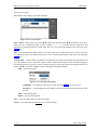
Setup Menu
Setup Menu is displayed after pressing „Menu“ softkey. Setup menu permits setting device’s
parameters. New parameters are saved into the non-volatile memory.
Figure 19 Setup menu
Required menu item is highlighted using cursor keys ▲,▼ or display softkeys. Highlighted
menu is selected by pressing SELECT key or „OK“ softkey.
Information
This menu displays information about the device. Items can’t be changed by the user.
Manufacturer
Model
Seial number
Software version
Hardware version
Device
This menu permits setting operational parameters of device.
Temperature unit
Temperature functions can be expressed in different units. Available units are °C (Celsius), °F
(Fahrenheit) and K (Kelvin).
Switching
Item defines the way how resistance value is changed. Value R1 is changed to value R2 in the time
interval T. Resistance connected to the output terminals can have different values during the time
interval T.
FAST
SMOOTH
VIA OPEN
Fastest possible switching method.
T is typically 400us.
Resistance during T is undefined. It can be higher or lower than R1 (R2).
Method with smalest possible resistance change.
T is typically 1ms.
Resistance during T can’t be higher than max (R1, R2) and can be lower than min
(R1, R2).
2 steps switching method. R1 is switched to OPEN and than to R2.
T is typically 1ms.
Operation manual
18
M632 Precision Resistance Decade
VIA SHORT
MEATEST
2 steps switching method. R1 is switched to SHORT and than to R2.
T is typically 1ms.
SHORT value is lower than min (R1, R2).
Platinum standard
Platinum thermometers can be simulated according to the different standards. Available standards are:
PT385 (68)
PT385 (90)
PT3916
PT3926
PT User
DIN, standard EN60751, temperature scale IPTS68
(A=3.90802e-3, B=-5.80195e-7, C=-4.2735e-12)
DIN, standard EN60751, temperature scale ITS90
(A=3.9083e-3, B=-5.775e-7, C=-4.18301e-12)
Pt3916 temperature curve
(A=3.9692e-3, B=-5.8495e-7, C=-4.2325e-12)
Pt3926 temperature curve
(A=3.9848e-3, B=-5.870e-7, C=-4.0e-12)
user defined temperature curve
(A=3.9083e-3, B=-5.775e-7, C=-4.18301e-12) – values can be changed
Platinum user coefficients
This menu permits A, B and C coefficients definition of the PT User platinum standard (see above).
Timings
This menu permits definition of different time dependent resistance curves. Each curve is defined by
the Timing table. Each row in the table contains information about resistance value and time for
which is this value applied. If the timing function is activated all rows are sequentially executed. User
can define more timing tables with different names. Number of rows is limited to 50.
User function curve
This menu permits definition of different conversion curves. Each curve is defined by the Lookup
table. Each row in the table contains information about value of simulated function and appropriate
resistance value. User can define more lookup tables with different names. Typical application is
definition table for simulation of non-standard resistance thermometers. Number of rows is limited to
100.
System
This menu permits setting system parameters of device.
Language
Language setting.
Backlight
Display backlight level setting.
Beeper volume
Beeper volume level setting.
Keyboard beep
Enables / Disables keyboard beep.
Time
Internal time setting.
Date
Internal date setting
19
Operation manual
MEATEST
M632 Precision Resistance Decade
Interface
This menu permits setting parameters of remote control interfaces.
Active bus
Active bus setting. Only active bus can be used for remote control.
RS232 Baudrate
RS232 communication baudrate setting. The same baudrate must be used in the controller.
GPIB Address
GPIB address setting. Each instrument connected to the GPIB bus must have a unique address.
LAN Settings
Ethernet parameters setting. Device use Telnet protocol. Default setting is:
DHCP
IP Address
Subnet mask
Default gateway
Port number
Host name
4.6.
ON
192.168.001.100
only valid if DHCP is OFF
255.255.255.000
only valid if DHCP is OFF
255.255.255.255
only valid if DHCP is OFF
23
M632_SN620031 only valid if DHCP is ON
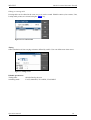
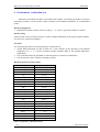
Calibration mode
In this mode resistance elements of the decade can be recalibrated. Access to the calibration
mode is from the setup Menu.
Correct password must be entered before calibration. Without correct password the access to
the calibration mode is refused. Default factory set calibration code is “2”. Return to standard mode is
possible after pushing the key ESC.
Figure 20 Password entry
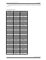
Recalibration procedure consists of measuring of 37 basic resistance values and entering their
actually measured data. Calibration point can be changes using display softkeys “Previous” and
“Next”. Calibration value of selected resistance can be change using cursor keys ▲,▼, ◄, ►.
Operation manual
20
M632 Precision Resistance Decade
MEATEST
Following table describes nominal values of calibration points and requested recalibration
accuracy:
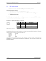
Calibration points M632
Standard
Nominal value
Requested Accuracy
R1
1,95 Ω
1 mΩ
R2
3,88 Ω
1 mΩ
R3
7,73 Ω
1 mΩ
R4
15,4 Ω
1 mΩ
R5
30,5 Ω
1 mΩ
R6
60,4 Ω
1 mΩ
R7
120 Ω
2 mΩ
R8
237 Ω
3 mΩ
R9
464 Ω
6 mΩ
R10
909 Ω
15 mΩ
R11
1,78 kΩ
30 mΩ
R12
3,48 kΩ
100 mΩ
R13
6,87 kΩ
250 mΩ
R14
13,5 kΩ
500 mΩ
R15
26,6 kΩ
1Ω
R16
52,2 kΩ
5Ω
R17
103 kΩ
10 Ω
R18
202 kΩ
20 Ω
R19
396 kΩ
40 Ω
R20
778 kΩ
80 Ω
R21
1,54 MΩ
200 Ω
R22
3,03 MΩ
400 Ω
R23
6,0 MΩ
1 kΩ
R24
12 MΩ
5 kΩ
R25
23 MΩ
50 kΩ
R26
48 MΩ
200 kΩ
R27
100 MΩ
500 kΩ
R28
200 MΩ
1 MΩ
R29
2,09 kΩ
40 mΩ
R30
4,14 kΩ
80 mΩ
R31
8,18 kΩ
100 mΩ
R32
16,1 kΩ
200 mΩ
R33
34,3 kΩ
500 mΩ
R34
75,3 kΩ
1Ω
R35
150 kΩ
4Ω
R36
301 kΩ
10 Ω
R37
602 kΩ
20 Ω
Table 1 M632 Calibration points
21
Operation manual
MEATEST
M632 Precision Resistance Decade
Process of calibration consists of measuring partial resistances and writting their actual values
into the decade:
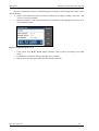
• Set the first calibration point (resistance element). Use display softkeys “Previous” and
“Next” to select the element.
• Measure resistance of the selected element. Use ohm-meter with appropriate accuracy in 4wire connection mode.
Figure 21 Calibration point screen
•
•
•
Using cursor keys ▲,▼, ◄, ► adjust resistance value in M632 according to the ohm
meter.
Confirm new calibration value by pressing “Save” softkey.
Repeat above described procedure for all resistance elements.
Operation manual
22
M632 Precision Resistance Decade
MEATEST
5. Performance verification test
Parameter verification procedure is described in the chapter. Verification procedure is based on
measuring resistance on the decade output terminals with standard multimeter in recommended
points.
Required equippment
• Ohm-meter nominal accuracy 0.001% in range 1 Ω to 1.2 MΩ (type Fluke 8508A or similar)
Decade setting
Switch decade to the resistance function. Connect standard multimeter to the decade output terminals.
Use four-wire connection technique.
Procedure
Use following procedure to perform parameter verification test:
1. Switch both instruments on and let them for 1 hour stabilise in the laboratory with ambient
temperature 23 ± 3 oC. Connect resistance decade terminals R4W to the standard ohm-meter
(multimeter).
2. Case of decade should be grounded or connected to the Lo terminal of multimeter.
3. Check resistance value in points according to Table I.
Maximal absolute deviations M632
Nominal value
M632 max. deviation
1Ω
2.0 mΩ
2Ω
2.0 mΩ
5Ω
2.1 mΩ
10 Ω
2.2 mΩ
16 Ω
2.2 mΩ
20 Ω
2.4 mΩ
50 Ω
3.0 mΩ
100 Ω
4.0 mΩ
200 Ω
6.0 mΩ
500 Ω
15 mΩ
1 kΩ
30 mΩ
2 kΩ
60 mΩ
5 kΩ
150 mΩ
10 kΩ
300 mΩ
20 kΩ
600 mΩ
50 kΩ
1.5 Ω
100 kΩ
3.0 Ω
200 kΩ
6.0 Ω
400 kΩ
20 Ω
500 kΩ
25 Ω
1 MΩ
50 Ω
1.2 MΩ
60 Ω
Table 2 Verification - allowed deviations
23
Operation manual
MEATEST
M632 Precision Resistance Decade
6. Remote control
Decade box can be controled via RS232, GPIB, LAN and USB interface. The decade can be
only controlled by one of interfaces at a time. It is therefore necessary to select ans set-up one of the
interfaces using the system menu. All interfaces shares the same commands except following
commands, which are intended only for use with RS232, LAN and USB interface:
SYSTem:LOCal
This command places decade in the “LOCAL” mode.
SYSTem:REMote
This command places decade in the “REMOTE” mode.
SYSTem:RWLock
This command places the decade in the “REMOTE” mode and locks all keys (including
LOCAL key) on front panel.
NOTE: If device is not in REMOTE mode all other commands are ignored by decade (for
RS232, LAN and USB interface). With the exception of Compatible commands which are
processed each time. GPIB interface places device in the “REMOTE” mode automatically by
opening the GPIB interface and therefore these commands are not intended for this interface.
6.1.
RS232 Interface
The decade box can be controled via standard RS232 interface.
Following equipment is required:
• M632 decade box
• Personal Computer (or other controling device) with RS232 port (USB-to-RS232 converter
is also possible)
• 9-pin D-SUB, 3-wire direct (1:1) male/female RS232 cable
The RS232 interface must be selected from decade system menu to be in operation (SETUP>Interface->Active bus). There is only one RS232 setting accesible from the decade system menu
under SETUP->Interface path:
RS232 Baudrate
1200, 2400, 4800, 9600, 19200, 38400, 57600 or 115200
Other RS232 parameters are fixed to the following settings:
Number of data bits
Number of stop bits
Parity
Handshake (XON/XOFF)
8
1
None
Off
RS232 connection
Pin
Label
I/O
Description
2
3
5
TXD
RXD
GND
output
input
-
Transmitter
Receiver
Ground
Figure 22 RS232 9 pin D-SUB MALE connector
Operation manual
24
M632 Precision Resistance Decade
MEATEST
Cable between decade and computer description (configuration 1:1)
Computer
D-Sub 1
2
3
5
Receiver
Transmitter
Ground
D-Sub 2
2
Transmitter
3
Receiver
5
Ground
M632
Table 3 RS232 cable connection
6.2.
GPIB Interface (option)
The decade box can be controled via GPIB (General Purpose Interface Bus) interface.
Following equipment is required:
•
•
•
M632 decade box with LAN, USB, IEEE488 bus option
Personal Computer (or other controling device) with GPIB interface
GPIB cable
The GPIB interface must be selected from decade system menu to be in operation (SETUP>Interface->Active bus). There is only one GPIB setting accesible from the decade system menu
under SETUP->Interface path:
GPIB Address
1 to 31
The instrument performs the following functions based on IEEE488 bus commands:
SH1, AH1, T5, L3, RL1, DC1
The instrument also recognizes the following general commands:
DCL Device Clear - resets the instrument to its basic state
SDC Selected Device Clear - resets the instrument to its basic state
GTL Go To Local - switches the remote control off
LLO Local Lock Out - switches the local control off, the instrument
cannot be controlled from the front panel
Commands are identical to the commands for RS-232 interface. Detailed
description is shown in chapter 8.2.
Figure 23 IEEE488 connector
25
Operation manual
MEATEST
6.3.
M632 Precision Resistance Decade
LAN Interface (option)
LAN Interface allows communication with decade box using Telnet protocol. A propper setting
must be established.
Following equipment is required:
•
•
•
M632 decade box with LAN, USB, IEEE488 bus option
Personal Computer (or other controling device) with LAN interface
LAN cable
The LAN interface must be selected from decade system menu to be in operation (SETUP->Interface>Active bus). There are folowing LAN settings accesible from decade system menu under SETUP>Interface->LAN Settings path (values are default ones):
DHCP
IP Address
Subnet mask
Default gateway
Port number
Host name
ON
192.168.001.100
only valid if DHCP is OFF
255.255.255.000
only valid if DHCP is OFF
255.255.255.255
only valid if DHCP is OFF
23
M632_SN620031 only valid if DHCP is ON
If DHCP (Dynamic Host Configuration Protocol) is enabled, the IP Address and all necessary settings
are done automatically and connection in Telnet protocol is done via “Host name” and “Port number”.
Otherwise the IP address, Subnest mask and Default gateway should be properly set. In this case
connection is done via “IP Address” and “Port number”.
Connection to decade box using Microsoft Telnet terminal with DHCP option enabled:
Figure 24 LAN connection 1
If connection is succesful following screen will appear:
Figure 25 LAN connection 2
Operation manual
26
M632 Precision Resistance Decade
6.4.
MEATEST
USB Interface (option)
The decade box can be controled via USB (Universal Serial Bus) interface.
Following equipment is required:
• M632 decade box with LAN, USB, IEEE488 bus option
• Personal Computer (or other controling device) with USB interface (USB type A
connector)
• Standard USB A-B cable
The USB interface must be selected from decade system menu to be in operation (SETUP->Interface>Active bus). There is no USB setting in the decade.
Decade box is equiped with USB type B connector.
Pin
Label
Description
1
2
3
4
+5V
DATADATA+
GND
Power supply
Data signal Data signal +
Ground
Figure 26 USB connector
Communication from user control program is performed via standard RS232 interface. Following
settings should be set on your PC for propper operation:
Baudrate
Data bits
Stop bits
Parity
9600 Bd
8
1
None
Also proper COM port must be selected. After connecting decade to your PC, virtual COM port
should appear in System Control panel of Microsoft Windows OS. This COM port is labeled “USB
Serial Port (COMxx)”.
27
Operation manual
MEATEST
6.5.
M632 Precision Resistance Decade
Command syntax
The commands described in this chapter can be issued through all buses (RS232/GPIB/LAN/USB).
All commands listed in this chapter are explained in two columns:
KEYWORD and PARAMETERS.
KEYWORD column includes the name of the command. Each command includes one or more
keywords. If a keyword is in brackets ( [ ] ), it is not mandatory. Non-mandatory commands are used
only to achieve compatibility with language standard SCPI.
Capitals designate the abbreviated form of the commands; extended form is written in lowercase.
Command parameters are in brackets (<>); each parameter is separated using a comma. Parameters in
brackets ( [ ] ) are not mandatory. Line ( | ) means “or” and is used to separate several alternative
parameters.
Semicolon ‘;’ is used to separate more commands written on one line.
E.g. :RES 100;:OUTP ON
Terminators:
For GPIB interface each command line must end with <lf>. Response from the device also returns
<lf>. For non GPIB interfaces <cr>, <lf> or <crlf> can be used as terminator. The device returns
<crlf> in this case. The device performs all commands written on one line of the program after it
receives terminator. Without terminator, the program line is not executed.
Description of abbreviations
<DNPD> = Decimal Numeric Program Data, this format is used to express decimal number with or
without the exponent.
<CPD> = Character Program Data. Usually, it represents a group of alternative character
parameters. E.g. {SERial|GPIB|USB|LAN}.
<SPD> = String Program Data (quoted string). This type of parameter is similar to CPD, but allows
transmission of more ISO characters.
<BOOL> = Boolean Program Data. This type of parameter has only two states 0 and 1. Parameter
can take form of integer value (0 or 1), or character alias (ON or OFF). Device always returns integer
value (0 or 1).
<UNIT> = unit parameter works in conjunction with DNPD parameter and specifies unit of DNPD
(numeric) value. Unit must be selected from predefined ones. If UNIT part is omitted, default one is
used. Query always returns actual unit.
? = A flag indicating a request for the value of the parameter specified by the command. No other
parameter than the question mark can be used.
(?) = A flag indicating a request for the parameter specified by the command. This command permits
a value to be set as well as requested.
<cr> =
carriage return. ASCII code 13. This code executes the program line.
<lf> =
line feed. ASCII code 10. This code executes the program line.
Operation manual
28
M632 Precision Resistance Decade
6.6.
MEATEST
SCPI Command Tree
This chapter sumarizes all public SCPI commands supported by device in alphabetic order. Detailed
description follows in next chapter.
:CALibration
:RESistance
:AMPLitude(?) <DNPD>
:SELect(?) <DNPD>
:SECure
:PASSword(?) <DNPD>
:EXIT
:DISPlay
:ANNotation
:CLOCk
:DATE
:FORMat(?) {MDYS|MDYA|DMYS|DMYO|DMYA|YMDS|YMDO}
[:STATe](?) {ON|OFF|1|0}
:BRIGhtness(?) <DNPD>
:LANGuage(?) {ENGLish|DEUTsch|FRENch|RUSSian|SPANish|CZECh}
:OUTPut
:SHORt(?) {ON|OFF|1|0}
[:STATe](?) {ON|OFF|1|0}
:SWITching(?) {FAST|SMOoth|OPEN|SHORt}
[:SOURce]
:NICKel
[:AMPLitude](?) <DNPD>[{CEL|FAR|K}]
:ZRESistance(?) <DNPD>[OHM]
:PLATinum
[:AMPLitude](?) <DNPD>[{CEL|FAR|K}]
:COEFficient(?) <DNPD>,<DNPD>,<DNPD>
:STANdard(?) {PT385A|PT385B|PT3916|PT3926|USER}
:ZRESistance(?) <DNPD>[OHM]
:RESistance
[:AMPLitude](?) <DNPD>[OHM]
:TIMing
:PAPPend <SPD>
:PCOunt? <DNPD>
:PRESet<IND_PRESET>
:NAME(?) <SPD>
:PDELete
:RAPPend <SPD>
:RCOunt? <DNPD>
:ROW<IND_ROW>
:AMPLitude(?) <SPD>
:RDELete
:SELect(?) <DNPD>
:UFUNction
[:AMPLitude](?) <DNPD>
:CURVe
:SELect(?) <DNPD>
:PAPPend <SPD>
:PCOunt? <DNPD>
:PRESet<IND_PRESET>
:NAME(?) <SPD>
29
Operation manual
MEATEST
M632 Precision Resistance Decade
:PDELete
:RAPPend <SPD>
:RCOunt? <DNPD>
:ROW<IND_ROW>
:AMPLitude(?) <SPD>
:RDELete
:UNIT(?) <SPD>
:STATus
:OPERation
:CONDition(?) <DNPD>
:ENABle(?) <DNPD>
[:EVENt]? <DNPD>
:NTRansition(?) <DNPD>
:PTRansition(?) <DNPD>
:QUEStionable
:CONDition(?) <DNPD>
:ENABle(?) <DNPD>
[:EVENt]? <DNPD>
:NTRansition(?) <DNPD>
:PTRansition(?) <DNPD>
:SYSTem
:BEEPer
:STATe(?) {ON|OFF|1|0}
:VOLume(?) <DNPD>
:COMMunicate
:BUS(?) {SERial|GPIB|USB|LAN}
:GPIB
:ADDRess(?) <DNPD>
:LAN
:ADDRess(?) <CPD>
:MASK(?) <CPD>
:GATE(?) <CPD>
:PORT(?) <DNPD>
:HOST(?) <CPD>
:DHCP(?) {ON|OFF|1|0}
:RESTart
:SERial
:BAUD(?) {1200|2400|4800|9600|19200|38400|57600|115200}
:DATE(?) <DNPD>,<DNPD>,<DNPD>
:ERRor
[:NEXT]? <CPD>
:KEY(?) <DNPD>
:LOCal
:PRESet
:REMote
:RWLock
:TIME(?) <DNPD>,<DNPD>,<DNPD>
:VERSion? <CPD>
:UNIT
:TEMPerature(?) {CEL|FAR|K}
*CLS
*ESE(?)
*ESR?
*IDN?
*OPC(?)
Operation manual
30
M632 Precision Resistance Decade
MEATEST
*OPT?
*RST
*SRE(?)
*STB?
*TST?
*WAI
6.7.
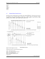
Standard Status Data Structures
Decade box meets standard protocol according to the standard IEEE488.2. The protocol can be used
for checking of error and status behavior of the device. It enables single-wire transmitting of SRQ
command. The conditions on which SRQ signal (local control request) is sent can be set with
parameters *STB?, *SRE?, *SRE, *ESR?, *ESE?, *ESE a *CLS.
Figure 27 Status register overview
Status data structure contains following registers:
STB – Status Byte Register
SRE – Service Request Enable Register
ESR – Event Status Register
ESE – Event Status Enable Register
Output Queue
31
Operation manual
MEATEST
M632 Precision Resistance Decade
STB Status Byte Register
STB is main register where information from other status registers and from output queue is collected.
Value of STB register is reset after switching on the device or after sending command *CLS. This
command reset the STB register except bit MAV, which remains set if the output queue is not empty.
STB register value can be read via serial message or through general query *STB?.
Bit configuration of Status Byte Register:
OSS
Operation Summary Status, bit 7. SCPI-defined. The OSS bit is set to 1 when the data in the
OSR (Operation Status Register) contains one or more enabled bits which are true.
RQS Request Service, bit 6. The bit is read as a part of status byte only when serial message is sent.
MSS Master Summary Status, bit 6. The MSS bit is set to 1 whenever bits ESB or MAV are 1 and
enabled (1) in the SRE. This bit can be read using the *STB? command. Its value is derived
from STB and SRE status.
ESB Event Summary Bit, bit 5. His value is derived from STB and SRE status. The ESB bit is set
to 1 when one or more enabled ESR bits are set to 1.
MAV Message Available, bit 4. The MAV bit is set to 1 whenever data is available in the IEEE488
Output Queue (the response on query is ready).
QSS Questionable Summary Status, bit 3. SCPI-defined. The QSS bit is set to 1 when the data in
the QSR (Questionable Status Register) contains one or more enabled bits which are true.
SRE Service Request Enable Register
The Service Request Enable Register suppresses or allows the STB bits. “0” value of a SRE bit
means, that the bit does not influence value of MSS bit. Value of any unmasked STB bit results in
setting of the MSS bit to the level “1” . SRE bit 6 is not influenced and its value is “0”. The SRE
register value can be set via the command *SRE followed by mask register value (0 – 191). The
register can be read with the command *SRE?. The register is automatically resets after switching the
decade box on. The register is not reset by the command *CLS.
ESR Event Status Register
Every bit of the EventStatusRegister corresponds to one event. Bit is set when the event is changed
and it remains set also when the event passed. The ESR is cleared when the power is turned on
(except bit PON which is set), and every time it is read via command *ESR? Or cleared with *CLS.
Bit configuration of Event Status Register:
PON
URQ
CME
EXE
DDE
QYE
OPC
Power On, bit 7. This event bit indicates that an off-to-on transition has occurred in the
device’s power supply.
User Request, bit 6. Bit is not used and it is always “0”.
Command Error, bit 5. This event bit indicates that an incorrectly formed command or query
has been detected by the instrument.
Execution Error, bit 4. This event bit indicates that the received command cannot be executed,
owing to the device state or the command parameter being out of limits.
Device Dependent Error, bit 3. This event bit indicates that an error has occurred which is
neither a Command Error, a Query Error, nor an Execution Error. A Device-specific Error is
any executed device operation that did not properly complete due to some condition, such as
overload.
Query Error, bit 2. The bit is set if the decade box is addressed as talker and output queue is
empty or if control unit did not pick up response before sending next query.
Operation Complete, bit 0. This event bit is generated in response to the *OPC command. It
indicates that the device has completed all selected pending operations.
ESE Event Status Enable Register
The Event Status Enable Register allows one or more events in the Event Status Register to be
reflected in the ESB summary-message bit. This register is defined for 8 bits, each corresponding to
Operation manual
32
M632 Precision Resistance Decade
MEATEST
the bits in the Event Status Register. The Event Status Enable Register is read with the common query
*ESE?. Data is returned as a binary-weighted value. The Event Status Enable Register is written to by
the common command, *ESE. Sending the *ESE common command followed by a zero clears the
ESE. The Event Status Enable Register is cleared upon power-on.
It suppresses or allows bits in ESR register. Value „0“ of a bit of ESE register suppresses influence of
appropriate bit of ESR register on value of sum bit of ESB status register. Setting of any unmask bit
of ESR register results in setting of ESB status register. ESE register value can be modified by
command *ESE followed by value of mask register (integer in range 0 –255). Reading of the register
can be performed with command *ESE?. The register is automatically reset after switching on. The
register is not reset with *CLS command.
Operation Status Register
Not used in the decade box.
Questionable Status Register
Not used in the decade box.
Output Queue
The Output Queue stores response messages until they are read from control unit. If there is at
minimum one sign in the output queue, MAV register (message available) is set. The Output Queue is
cleared upon power-on and after reading all signs from output queue.
Error Queue
The Error Queue stores error messages. They are placed in a “first in, first out” queue.
The queue is read destructively using the query command “SYSTem:ERRor?” to obtain a code
number and errro message. The query “SYSTem:ERRor?” can be used to read errors in the queue
until it is empty, when the message “0, No Error” will be returned.
6.8.
SCPI Standard Commands
This chapter describes standard SCPI commands.
*IDN?
Syntax:
*IDN?
Description:
This command returns the identification of the manufacturer, model, serial number and
firmware revision.
Parameters:
<CPD>
manufacturer
<CPD>
model
<DNPD> serial number
<DNPD> frimware version
Remarks:
Overlapped command
Example:
*IDN? Response: MEATEST,M632,620151,1.00
33
Operation manual
MEATEST
M632 Precision Resistance Decade
*OPC
Syntax:
*OPC
Description:
This command sets the OPC bit in the ESR (Event Status Register) when all pending
operations are complete.
Parameters:
None
Remarks:
Overlapped command
Example:
*OPC
*OPC?
Syntax:
*OPC?
Description:
This command returns “1” to the output queue after all pending operations inside decade
box are complete.
Parameters:
<DNPD>
always returns 1
Remarks:
Sequential command
Example:
*OPC? Response: 1
*OPT?
Syntax:
*OPT?
Description:
This command return the instrument’s hardware fitment. The only parameter returns
presence of GPIB/LAN/USB interface.
Parameters:
<DNPD>
0 – extended interface not present, 1 – extended interface present
Remarks:
Overlapped command
Example:
*OPT? Response: 1
*WAI
Syntax:
*WAI
Description:
Prevents the instrument from executing any further commands or queries until all
previous remote commands have been executed.
Parameters:
None
Remarks:
Sequential command
Example:
*WAI
Operation manual
34
M632 Precision Resistance Decade
MEATEST
*RST
Syntax:
*RST
Description:
This command resets the device to its initial status.
Parameters:
None
Remarks:
Sequential command
Example:
*RST
*TST?
Syntax:
*TST?
Description:
This command launches internal self-test and returns result.
Parameters:
<DNPD>
0 – test passed, 1 – test failed
Remarks:
Sequential command
Example:
*TST? Response: 0
*STB?
Syntax:
*STB?
Description:
This query returns content of register STB, which carries the MSS bit status.
Parameters:
<DNPD>
Status byte register, Range 0 … 255
Remarks:
Overlapped command
Example:
*STB? Response: 0
*SRE
Syntax:
*SRE
*SRE?
Description:
This command allows set condition of the Service Request Enable register. Since bit 6 is
not used, the maximum value is 191.
Parameters:
<DNPD>
Service Request Enable register
Remarks:
Overlapped command
Example:
*SRE 2
*SRE? Response: 2
35
Operation manual
MEATEST
M632 Precision Resistance Decade
*ESR?
Syntax:
*ESR?
Description:
This query returns the contents of the Event Status Register and clears the register.
Parameters:
<DNPD>
Event Status Register
Remarks:
Overlapped command
Example:
*ESR? Response: 0
*ESE
Syntax:
*ESE
*ESE?
Description:
This command programs the Event Status Enable register bits.
Parameters:
<DNPD>
Event Status Enable register, Range 0 … 255
Remarks:
Overlapped command
Example:
*ESE 2
*ESE? Response: 2
*CLS
Syntax:
*CLS
Description:
This command clears all status data structures in the device i.e. Event Status Register,
Status Byte Register except the MAV bit, Operation Status Register, Questionable Status
Register. Also error queue is cleared. Output queue is unaffected.
Parameters:
None
Remarks:
Overlapped command
Example:
*CLS
Operation manual
36
M632 Precision Resistance Decade
6.9.
MEATEST
SCPI Commands
This chapters describes all public SCPI commands in detailed form. The commands here are in
alphabetic order.
:CALibration:RESistance:AMPLitude
Syntax:
:CALibration:RESistance:AMPLitude <DNPD>
:CALibration:RESistance:AMPLitude?
Description:
This command sets calibration value of particular internal resistance standard at output
terminals including all parasitic resistances inside decade box.
Parameters:
<DNPD>
Standard resistance value in Ohms. Ranges and default values varies
in accordance to selected resistance etalon (see table “Calibration
points M632”).
Remarks:
This command requires "Calibration" access
Overlapped command
Value is not affected by reset
Example:
CAL:RES:AMPL 1.944
CAL:RES:AMPL? Response: 1.944000E+00
:CALibration:RESistance:SELect
Syntax:
:CALibration:RESistance:SELect <DNPD>
:CALibration:RESistance:SELect?
Description:
This command enters calibration mode and selects internal resistance standard for
calibration. Output terminals are automatically switched-on.
Parameters:
<DNPD>
Range 1 ... Max. Resistance Count, one based index of resistance
standard
Remarks:
This command requires "Calibration" access
Overlapped command
Example:
CAL:RES:SEL 1
CAL:RES:SEL? Response: 1
:CALibration:SECure:PASSword
Syntax:
:CALibration:SECure:PASSword <DNPD>
Description:
This command validates entered password and enables calibration access if verification
is successful. Acces is invalidated after reset or if CAL:SEC:EXIT command is issued.
Calibration password can be changed from decade system menu SETUP->Calibration>Change password.
Parameters:
<DNPD>
Range 0 ... 4294967295 (default 0)
Remarks:
Overlapped command
Example:
37
Operation manual
MEATEST
M632 Precision Resistance Decade
CAL:SEC:PASS 0
:CALibration:SECure:EXIT
Syntax:
:CALibration:SECure:EXIT
Description:
This command exits calibration mode and access.
Parameters:
None
Remarks:
Overlapped command
Example:
CAL:SEC:EXIT
:DISPlay:ANNotation:CLOCk:DATE:FORMat
Syntax:
:DISPlay:ANNotation:CLOCk:DATE:FORMat <CPD>
:DISPlay:ANNotation:CLOCk:DATE:FORMat?
Description:
This command sets format of date displayed on device screen.
Parameters:
<CPD>
{MDYS|MDYA|DMYS|DMYO|DMYA|YMDS|YMDO} (default MDYS)
·MDYS
M/D/Y format
(M-month, D-day, Y-year)
·MDYA
M-D-Y format
·DMYS
D/M/Y format
·DMYO
D.M.Y format
·DMYA
D-M-Y format
·YMDS
Y/M/D format
·YMDO
Y.M.D format
Remarks:
Overlapped command
Value is not affected by reset
Example:
DISP:ANN:CLOC:DATE:FORM MDYS
DISP:ANN:CLOC:DATE:FORM? Response: MDYS
:DISPlay:ANNotation:CLOCk[:STATe]
Syntax:
:DISPlay:ANNotation:CLOCk[:STATe] <BOOL>
:DISPlay:ANNotation:CLOCk[:STATe]?
Description:
This command enables/disables showing actual time in title on device screen
Parameters:
<BOOL>
{ON|OFF|1|0} (default 1)
·ON
actual time is shown
·OFF
actual time is hidden
·1
same as ON
·0
same as OFF
Remarks:
Overlapped command
Value is not affected by reset
Example:
DISP:ANN:CLOC ON
DISP:ANN:CLOC? Response: 1
Operation manual
38
M632 Precision Resistance Decade
MEATEST
:DISPlay:BRIGhtness
Syntax:
:DISPlay:BRIGhtness <DNPD>
:DISPlay:BRIGhtness?
Description:
This command sets brightness of device display.
Parameters:
<DNPD>
Range 0.0 ... 1.0 (default 1.0), 0.0 – Min, 1.0 – Max brightness
Remarks:
Overlapped command
Value is not affected by reset
Example:
DISP:BRIG 1.0
DISP:BRIG? Response: 1.000000E+00
:DISPlay:LANGuage
Syntax:
:DISPlay:LANGuage <CPD>
:DISPlay:LANGuage?
Description:
This command sets language that is used on device display.
Parameters:
<CPD>
{ENGLish|DEUTsch|FRENch|RUSSian|SPANish|CZECh}
(default ENGL)
·ENGLish
english version
·DEUTsch
deutsch version
·FRENch
french version
·RUSSian
russian version
·SPANish
spanish version
·CZECh
czech version
Remarks:
Overlapped command
Value is not affected by reset
Example:
DISP:LANG ENGL
DISP:LANG? Response: ENGL
:OUTPut:SHORt
Syntax:
:OUTPut:SHORt <BOOL>
:OUTPut:SHORt?
Description:
This command turns on short function. “Short” is activated only if output terminals are
switched on (see OUTP:STAT command).
Parameters:
<BOOL>
{ON|OFF|1|0} (default 0)
·ON
short is set if output is on
·OFF
resistance is set if output is on
·1
same as ON
·0
same as OFF
Remarks:
Overlapped command
Value is set to default after reset
Example:
OUTP:SHOR ON
39
Operation manual
MEATEST
M632 Precision Resistance Decade
OUTP ON
OUTP:SHOR? Response: 1
:OUTPut[:STATe]
Syntax:
:OUTPut[:STATe] <BOOL>
:OUTPut[:STATe]?
Description:
This command switches ON/OFF output terminals. This command operates in
conjunction with OUTP:SHOR command:
OUTP:STAT
OFF
OFF
ON
ON
OUTP:SHOR
OFF
ON
OFF
ON
Output terminals
Open
Open
Resistance
Short
Table 4 OUTPut command structure
Parameters:
<BOOL>
{ON|OFF|1|0} (default 0)
·ON
output terminals are switched on
·OFF
output terminals are switched off
·1
same as ON
·0
same as OFF
Remarks:
Overlapped command
Value is set to default after reset
Example:
OUTP ON
OUTP? Response: 1
:OUTPut:SWITching
Syntax:
:OUTPut:SWITching <CPD>
:OUTPut:SWITching?
Description:
If output amplitude is changed and output terminals are already switched on, some
glitches appear at output terminals. This setting allows selecting a method how new
resistance at output terminals is achieved.
Parameters:
<CPD>
{FAST|SMOoth|OPEN|SHORt} (default FAST)
·FAST
new resistance is set as fast as possible
·SMOoth new resistance is set with minimal ouput changes
·OPEN
open function is activated before new resistance is set
·SHORt
short function is activated before new resistance is set
Remarks:
Overlapped command
Value is not affected by reset
Example:
OUTP:SWIT FAST
OUTP:SWIT? Response: FAST
[:SOURce]:NICKel[:AMPLitude]
Syntax:
[:SOURce]:NICKel[:AMPLitude] <DNPD>[<UNIT>]
[:SOURce]:NICKel[:AMPLitude]?
Operation manual
40
M632 Precision Resistance Decade
MEATEST
Description:
This command sets temperature in Nickel mode. Node SOUR:NICK also selects
“NICKEL” function if not already selected. If unit parameter is part of temperature, new
unit is set.
Parameters:
<DNPD>
temperature at Nickel function. Default value is 100.0 °C.
<UNIT>
{CEL|FAR|K}
·CEL
degrees of Celsius
·FAR
degrees of Fahrenheit
·K
Kelvin
Remarks:
Overlapped command
Value is set to default after reset
Example:
NICK 100.0
NICK? Response: 1.000000E+02 CEL
[:SOURce]:NICKel:ZRESistance
Syntax:
[:SOURce]:NICKel:ZRESistance <DNPD>[<UNIT>]
[:SOURce]:NICKel:ZRESistance?
Description:
This command sets resistance at 0 °C for Nickel function.
Parameters:
<DNPD>
Range 10.0 ... 20000.0 (default 100.0).
<UNIT>
{OHM}
·OHM
Remarks:
Overlapped command
Value is not affected by reset
Example:
NICK:ZRES 100.0
NICK:ZRES? Response: 1.000000E+02 OHM
[:SOURce]:PLATinum[:AMPLitude]
Syntax:
[:SOURce]:PLATinum[:AMPLitude] <DNPD>[<UNIT>]
[:SOURce]:PLATinum[:AMPLitude]?
Description:
This command sets temperature in Platinum mode. Node SOUR:PLAT also selects
“PLATINUM” function if not already selected. If unit parameter is part of temperature,
new unit is set.
Parameters:
<DNPD>
temperature at Platinum function. Default value is 100.0 °C.
<UNIT>
{CEL|FAR|K}
·CEL
degrees of Celsius
·FAR
degrees of Fahrenheit
·K
Kelvin
Remarks:
Overlapped command
Value is set to default after reset
Example:
PLAT 100.0
PLAT? Response: 1.000000E+02 CEL
41
Operation manual
MEATEST
M632 Precision Resistance Decade
[:SOURce]:PLATinum:COEFficient
Syntax:
[:SOURce]:PLATinum:COEFficient <DNPD>,<DNPD>,<DNPD>
[:SOURce]:PLATinum:COEFficient?
Description:
This command allows to define Coefficients (A, B, C) used for “User” Platinum standard
scale.
Parameters:
<DNPD>
Range 3.0e-3 ... 5.0e-3 (default 3.9083e-3), Coefficient A
<DNPD>
Range -7.0e-7 ... -5.0e-7 (default -5.775e-7), Coefficient B
<DNPD>
Range -5.0e-12 ... -3.0e-12 (default -4.18301e-12), Coefficient C
Remarks:
Overlapped command
Value is not affected by reset
Example:
PLAT:COEF 3.9083e-3,-5.775e-7,-4.18301e-12
PLAT:COEF? Response: 3.908300E-03,-5.775000E-07,-4.183010E-12
[:SOURce]:PLATinum:STANdard
Syntax:
[:SOURce]:PLATinum:STANdard <CPD>
[:SOURce]:PLATinum:STANdard?
Description:
This command selects Platinum temperature standard.
Parameters:
<CPD>
{PT385A|PT385B|PT3916|PT3926|USER} (default PT385A)
·PT385A Pt385 (68) standard
·PT385B
Pt385 (90) standard
·PT3916
Pt3916 standard
·PT3926
Pt3926 standard
·USER
User (see PLAT:COEF command)
Remarks:
Overlapped command
Value is not affected by reset
Example:
PLAT:STAN PT385A
PLAT:STAN? Response: PT385A
[:SOURce]:PLATinum:ZRESistance
Syntax:
[:SOURce]:PLATinum:ZRESistance <DNPD>[<UNIT>]
[:SOURce]:PLATinum:ZRESistance?
Description:
This command sets resistance at 0 °C for Platinum function.
Parameters:
<DNPD>
Range 10.0 ... 20000.0 (default 100.0).
<UNIT>
{OHM}
·OHM
Remarks:
Overlapped command
Value is not affected by reset
Example:
PLAT:ZRES 100.0
PLAT:ZRES? Response: 1.000000E+02 OHM
Operation manual
42
M632 Precision Resistance Decade
MEATEST
[:SOURce]:RESistance[:AMPLitude]
Syntax:
[:SOURce]:RESistance[:AMPLitude] <DNPD>[<UNIT>]
[:SOURce]:RESistance[:AMPLitude]?
Description:
This command sets amplitude in Resistance mode. Node SOUR:RES also selects
“RESISTANCE” function if not already selected. Optionaly unit can be enclosed.
Parameters:
<DNPD>
Range 1.0 ... 1.2e6, default 100.0
<UNIT>
{OHM}
·OHM
Remarks:
Overlapped command
Value is set to default after reset
Example:
RES 100.0
RES? Response: 1.000000E+02 OHM
[:SOURce]:TIMing:PAPPend
Syntax:
[:SOURce]:TIMing:PAPPend <SPD>
Description:
This command appends new preset into timing function. The new appended preset has
empty timing table and new records should be also appended (see
TIM:PRES<index>:RAPP). The new preset has its own index and can be obtained by
TIM:PCO command.
Parameters:
<SPD>
Quoted preset name. Upper alpha, lower alpha, digits and spaces are
allowable. Maximum string size is 10 characters.
Remarks:
Overlapped command
Example:
TIM:PAPP "TIME2"
[:SOURce]:TIMing:PCOunt?
Syntax:
[:SOURce]:TIMing:PCOunt?
Description:
This command retreives actual number of timing presets. This number represents
maximum index used in preset commands.
Parameters:
<DNPD>
Integer value representing preset count
Remarks:
Overlapped command
Example:
TIM:PCO? Response: 1
[:SOURce]:TIMing:PRESet<IND_PRESET>:NAME
Syntax:
[:SOURce]:TIMing:PRESet<IND_PRESET>:NAME <SPD>
[:SOURce]:TIMing:PRESet<IND_PRESET>:NAME?
Description:
This command allows reading and changing preset name. The preset must exist before its
name is changed or read.
Parameters:
43
Operation manual
MEATEST
M632 Precision Resistance Decade
<IND_PRESET> Range 1 ... Preset count (1 - if omitted)
<SPD>
Quoted preset name. Upper alpha, lower alpha, digits and spaces are
allowable. Maximum string size is 10 characters.
Remarks:
Overlapped command
Example:
TIM:PRES2:NAME "TIME 1s"
TIM:PRES2:NAME? Response: "TIME 1s"
[:SOURce]:TIMing:PRESet<IND_PRESET>:PDELete
Syntax:
[:SOURce]:TIMing:PRESet<IND_PRESET>:PDELete
Description:
This command allows deleting existing preset. The preset will be deleted including
particular timing table.
Parameters:
<IND_PRESET>
Range 1 ... Preset count (1 - if omitted)
Remarks:
Overlapped command
Example:
TIM:PRES1:PDEL
[:SOURce]:TIMing:PRESet<IND_PRESET>:RAPPend
Syntax:
[:SOURce]:TIMing:PRESet<IND_PRESET>:RAPPend <SPD>
Description:
This command appends new record at the end of timing table.
Parameters:
<IND_PRESET> Range 1 ... 255 (1 - if omitted)
<SPD>
Quoted string representing amplitude. The amplitude consists of two
float numeric fields separated by comma. The first one represents
timing interval in seconds and the second one amplitude in Ohms.
Remarks:
Overlapped command
Example:
TIM:PRES1:RAPP "0.5,220.0"
[:SOURce]:TIMing:PRESet<IND_PRESET>:RCOunt?
Syntax:
[:SOURce]:TIMing:PRESet<IND_PRESET>:RCOunt?
Description:
This commands returns actual number of records in timing table.
Parameters:
<IND_PRESET> Range 1 ... Preset count (1 - if omitted)
<DNPD>
Integer value representing number of records
Remarks:
Overlapped command
Example:
TIM:PRES1:RCO? Response: 6
Operation manual
44
M632 Precision Resistance Decade
MEATEST
[:SOURce]:TIMing:PRESet<IND_PRESET>:ROW<IND_ROW>:AMPLitude
Syntax:
[:SOURce]:TIMing:PRESet<IND_PRESET>:ROW<IND_ROW>:AMPLitude <SPD>
[:SOURce]:TIMing:PRESet<IND_PRESET>:ROW<IND_ROW>:AMPLitude?
Description:
This command sets / retreives selected row in timing table.
Parameters:
<IND_PRESET> Range 1 ... Preset count (1 - if omitted)
<IND_ROW>
Range 1 ... Row count (1 - if omitted)
<SPD>
Quoted string representing amplitude. The amplitude consists of two
float numeric fields separated by comma. The first one represents
timing interval in seconds and the second one amplitude in Ohms.
Remarks:
Overlapped command
Example:
TIM:PRES2:ROW1:AMPL "0.5,220.0"
TIM:PRES2:ROW1:AMPL? Response: " 5.000000E-01,2.200000E+02"
[:SOURce]:TIMing:PRESet<IND_PRESET>:ROW<IND_ROW>:RDELete
Syntax:
[:SOURce]:TIMing:PRESet<IND_PRESET>:ROW<IND_ROW>:RDELete
Description:
This command deletes row from timing table.
Parameters:
<IND_PRESET>
Range 1 ... Preset count (1 - if omitted)
<IND_ROW>
Range 1 ... Row count (1 - if omitted)
Remarks:
Overlapped command
Example:
TIM:PRES2:ROW1:RDEL
[:SOURce]:TIMing:SELect
Syntax:
[:SOURce]:TIMing:SELect <DNPD>
[:SOURce]:TIMing:SELect?
Description:
This command selects timing preset. Selected preset is the preset that is shown on device
display and has no effect on other SOUR:TIM commands.
Parameters:
<DNPD>
Range 1 ... Preset count (default 1), one based index of preset
Remarks:
Overlapped command
Value is not affected by reset
Example:
TIM:SEL 1
TIM:SEL? Response: 1
[:SOURce]:UFUNction[:AMPLitude]
Syntax:
[:SOURce]:UFUNction[:AMPLitude] <DNPD>
[:SOURce]:UFUNction[:AMPLitude]?
Description:
This command sets amplitude in USER FUNCTION mode. Node SOUR:UFUN also
selects “USER FUNCTION” function if not already selected.
Parameters:
45
Operation manual
MEATEST
M632 Precision Resistance Decade
<DNPD>
Range depends on translation curve, default value is 1.0 or minimal
value that can be set
Remarks:
Overlapped command
Value is set to default after reset
Example:
UFUN 1.0
UFUN? Response: 1.000000E+00
[:SOURce]:UFUNction:CURVe:SELect
Syntax:
[:SOURce]:UFUNction:CURVe:SELect <DNPD>
[:SOURce]:UFUNction:CURVe:SELect?
Description:
This command selects curve preset in User function mode.
Parameters:
<DNPD>
Range 1 ... Curve preset count (default 1), one based index of preset
Remarks:
Overlapped command
Value is not affected by reset
Example:
UFUN:CURV:SEL 1
UFUN:CURV:SEL? Response: 1
[:SOURce]:UFUNction:CURVe:PAPPend
Syntax:
[:SOURce]:UFUNction:CURVe:PAPPend <SPD>
Description:
This command appends new curve preset into User function. The new appended preset
has empty curve table and new records should be also appended (see
UFUN:CURV:PRES<index>:RAPP). The new preset has its own index and can be
obtained by UFUN:CURV:PCO command.
Parameters:
<SPD>
Quoted curve preset name. Upper alpha, lower alpha, digits and
spaces are allowable. Maximum string size is 10 characters.
Remarks:
Overlapped command
Example:
UFUN:CURV:PAPP "CURVE 2"
[:SOURce]:UFUNction:CURVe:PCOunt?
Syntax:
[:SOURce]:UFUNction:CURVe:PCOunt?
Description:
This command retreives actual number of user function presets. This number represents
maximum index used in preset commands.
Parameters:
<DNPD>
Integer value representing number of preset count
Remarks:
Overlapped command
Example:
UFUN:CURV:PCO? Response: 1
Operation manual
46
M632 Precision Resistance Decade
MEATEST
[:SOURce]:UFUNction:CURVe:PRESet<IND_PRESET>:NAME
Syntax:
[:SOURce]:UFUNction:CURVe:PRESet<IND_PRESET>:NAME <SPD>
[:SOURce]:UFUNction:CURVe:PRESet<IND_PRESET>:NAME?
Description:
This command allows reading and changing preset name. The preset must exist before its
name is changed or read.
Parameters:
<IND_PRESET> Range 1 ... Curve preset count (1 - if omitted)
<SPD>
Quoted preset name. Upper alpha, lower alpha, digits and spaces are
allowable. Maximum string size is 10 characters.
Remarks:
Overlapped command
Example:
UFUN:CURV:PRES2:NAME "CURVE 2"
UFUN:CURV:PRES2:NAME? Response: "CURVE 2"
[:SOURce]:UFUNction:CURVe:PRESet<IND_PRESET>:PDELete
Syntax:
[:SOURce]:UFUNction:CURVe:PRESet<IND_PRESET>:PDELete
Description:
This command allows deleting existing preset. The preset will be deleted including
particular curve table.
Parameters:
<IND_PRESET>
Range 1 ... Curve preset count (1 - if omitted)
Remarks:
Overlapped command
Example:
UFUN:CURV:PRES1:PDEL
[:SOURce]:UFUNction:CURVe:PRESet<IND_PRESET>:RAPPend
Syntax:
[:SOURce]:UFUNction:CURVe:PRESet<IND_PRESET>:RAPPend <SPD>
Description:
Parameters:
<IND_PRESET> Range 1 ... Curve preset count (1 - if omitted)
<SPD>
Quoted string representing amplitude. The amplitude consists of two
float numeric fields separated by comma. The first one represents
amplitude in “User Function” units and the second one amplitude in
Ohms.
Remarks:
Overlapped command
Example:
UFUN:CURV:PRES1:RAPP "10.6,220.0"
[:SOURce]:UFUNction:CURVe:PRESet<IND_PRESET>:RCOunt?
Syntax:
[:SOURce]:UFUNction:CURVe:PRESet<IND_PRESET>:RCOunt?
Description:
This commands returns actual number of records in curve table.
Parameters:
<IND_PRESET> Range 1 ... Curve preset count (1 - if omitted)
<DNPD>
Integer value representing number of records for particular curve table
Remarks:
Overlapped command
47
Operation manual
MEATEST
M632 Precision Resistance Decade
Example:
UFUN:CURV:PRES1:RCO? Response: 2
[:SOURce]:UFUNction:CURVe:PRESet<IND_PRESET>:ROW<IND_ROW>:AMPLitude
Syntax:
[:SOURce]:UFUNction:CURVe:PRESet<IND_PRESET>:ROW<IND_ROW>:AMPLitu
de <SPD>
[:SOURce]:UFUNction:CURVe:PRESet<IND_PRESET>:ROW<IND_ROW>:AMPLitu
de?
Description:
This command sets / retreives selected row in curve table.
Parameters:
<IND_PRESET> Range 1 ... 255 (1 - if omitted)
<IND_ROW>
Range 1 ... 255 (1 - if omitted)
<SPD>
Quoted string representing amplitude. The amplitude consists of two
float numeric fields separated by comma. The first one represents
amplitude in “User Function” units and the second one amplitude in
Ohms.
Remarks:
Overlapped command
Example:
UFUN:CURV:PRES1:ROW1:AMPL "10.6,220.0"
UFUN:CURV:PRES1:ROW1:AMPL? Response: "1.060000E+01,2.200000E+2"
[:SOURce]:UFUNction:CURVe:PRESet<IND_PRESET>:ROW<IND_ROW>:RDELete
Syntax:
[:SOURce]:UFUNction:CURVe:PRESet<IND_PRESET>:ROW<IND_ROW>:RDELete
Description:
This command deletes row from curve table.
Parameters:
<IND_PRESET>
Range 1 ... Curve preset count (1 - if omitted)
<IND_ROW>
Range 1 ... Row count (1 - if omitted)
Remarks:
Overlapped command
Example:
UFUN:CURV:PRES1:ROW1:RDEL
[:SOURce]:UFUNction:CURVe:PRESet<IND_PRESET>:UNIT
Syntax:
[:SOURce]:UFUNction:CURVe:PRESet<IND_PRESET>:UNIT <SPD>
[:SOURce]:UFUNction:CURVe:PRESet<IND_PRESET>:UNIT?
Description:
Parameters:
<IND_PRESET> Range 1 ... Curve presetcount (1 - if omitted)
<SPD>
Quoted user function unit. Upper alpha, lower alpha, digits and spaces
are allowable. Maximum string size is 4 characters.
Remarks:
Overlapped command
Example:
UFUN:CURV:PRES1:UNIT "N"
UFUN:CURV:PRES1:UNIT? Response: "N"
Operation manual
48
M632 Precision Resistance Decade
MEATEST
:STATus:OPERation:CONDition
Syntax:
:STATus:OPERation:CONDition?
Description:
This query returns the content of Operational Condition register. It is a decimal value
which corresponds to the binary-weighted sum of all bits in the register. Register is not
cleared after this query. The response to the query therefore represents an instantaneous
'Snapshot' of the register state, at the time that the query was accepted.
Parameters:
<DNPD>
Operational Condition register
Remarks:
Overlapped command
Example:
STAT:OPER:COND? Response: 2
:STATus:OPERation:ENABle
Syntax:
:STATus:OPERation:ENABle <DNPD>
:STATus:OPERation:ENABle?
Description:
This command enables bits in the Operational Data Enable register. Selected bits are
summarized at bit 7 (OSS) of the IEEE488.2 Status Byte register.
Parameters:
<DNPD>
Operational Data Enable register
Remarks:
Overlapped command
Example:
STAT:OPER:ENAB 2
STAT:OPER:ENAB? Response: 2
:STATus:OPERation[:EVENt]?
Syntax:
:STATus:OPERation[:EVENt]?
Description:
This query returns the content of Operational Data Event register. It is a decimal value
which corresponds to the binary-weighted sum of all bits set in the register. Register is
cleared after this query.
Parameters:
<DNPD>
Operational Data Event register
Remarks:
Overlapped command
Example:
STAT:OPER? Response: 0
:STATus:OPERation:NTRansition
Syntax:
:STATus:OPERation:NTRansition <DNPD>
:STATus:OPERation:NTRansition?
Description:
This comman allows set Operation Negative Transition Register. It is a decimal value
which corresponds to the binary-weighted sum of all bits set in the register. Setting a bit
in the negative transition filter shall cause a 1 to 0 transition in the corresponding bit of
the associated condition register to cause a 1 to be written in the associated bit of the
corresponding event register.
Parameters:
49
Operation manual
MEATEST
M632 Precision Resistance Decade
<DNPD>
Operation Negative Transition Register, Range 0… 32767
Remarks:
Overlapped command
Example:
STAT:OPER:NTR 2
STAT:OPER:NTR? Response: 2
:STATus:OPERation:PTRansition
Syntax:
:STATus:OPERation:PTRansition <DNPD>
:STATus:OPERation:PTRansition?
Description:
This comman allows set Operation Positive Transition Register. It is a decimal value
which corresponds to the binary-weighted sum of all bits set in the register. Setting a bit
in the positive transition filter shall cause a 0 to 1 transition in the corresponding bit of
the associated condition register to cause a 1 to be written in the associated bit of the
corresponding event register.
Parameters:
<DNPD>
Operation Positive Transition Register, Range 0 … 32767
Remarks:
Overlapped command
Example:
STAT:OPER:PTR 1.0
STAT:OPER:PTR? Response: 1.000000E+00
:STATus:QUEStionable:CONDition
Syntax:
:STATus:QUEStionable:CONDition?
Description:
This query returns the content of Questionable Condition register. It is a decimal value
which corresponds to the binary-weighted sum of all bits in the register. Register is not
cleared after this query. The response to the query therefore represents an instantaneous
'Snapshot' of the register state, at the time that the query was accepted.
Parameters:
<DNPD>
Questionable Condition register
Remarks:
Overlapped command
Example:
STAT:QUES:COND? Response: 2
:STATus:QUEStionable:ENABle
Syntax:
:STATus:QUEStionable:ENABle <DNPD>
:STATus:QUEStionable:ENABle?
Description:
This command enables bits in the Questionable Data Enable register. Selected bits are
summarized at bit 3 (QSS) of the IEEE488.2 Status Byte register.
Parameters:
<DNPD>
Questionable Data Enable register
Remarks:
Overlapped command
Example:
STAT:QUES:ENAB 2
STAT:QUES:ENAB? Response: 2
Operation manual
50
M632 Precision Resistance Decade
MEATEST
:STATus:QUEStionable[:EVENt]?
Syntax:
:STATus:QUEStionable[:EVENt]?
Description:
This query returns the content of Questionable Data Event register. It is a decimal value
which corresponds to the binary-weighted sum of all bits set in the register. Register is
cleared after this query.
Parameters:
<DNPD>
Questionable Data Event register
Remarks:
Overlapped command
Example:
STAT:QUES? Response: 0
:STATus:QUEStionable:NTRansition
Syntax:
:STATus:QUEStionable:NTRansition <DNPD>
:STATus:QUEStionable:NTRansition?
Description:
This comman allows set Questionable Negative Transition Register. It is a decimal value
which corresponds to the binary-weighted sum of all bits set in the register. Setting a bit
in the negative transition filter shall cause a 1 to 0 transition in the corresponding bit of
the associated condition register to cause a 1 to be written in the associated bit of the
corresponding event register.
Parameters:
<DNPD>
Questionable Negative Transition Register, Range 0… 32767
Remarks:
Overlapped command
Example:
STAT:QUES:NTR 2
STAT:QUES:NTR? Response: 2
:STATus:QUEStionable:PTRansition
Syntax:
:STATus:QUEStionable:PTRansition <DNPD>
:STATus:QUEStionable:PTRansition?
Description:
This comman allows set Questionable Positive Transition Register. It is a decimal value
which corresponds to the binary-weighted sum of all bits set in the register. Setting a bit
in the positive transition filter shall cause a 0 to 1 transition in the corresponding bit of
the associated condition register to cause a 1 to be written in the associated bit of the
corresponding event register.
Parameters:
<DNPD>
Questionable Positive Transition Register, Range 0… 32767
Remarks:
Overlapped command
Example:
STAT:QUES:PTR 2
STAT:QUES:PTR? Response: 2
:SYSTem:BEEPer:STATe
Syntax:
:SYSTem:BEEPer:STATe <BOOL>
:SYSTem:BEEPer:STATe?
Description:
51
Operation manual
MEATEST
M632 Precision Resistance Decade
This command sets state of device beeper.
Parameters:
<BOOL>
{ON|OFF|1|0} (default 1)
·ON
device system beeper is enabled
·OFF
device system beeper is disabled
·1
same as ON
·0
same as OFF
Remarks:
Overlapped command
Value is not affected by reset
Example:
SYST:BEEP:STAT ON
SYST:BEEP:STAT? Response: 1
:SYSTem:BEEPer:VOLume
Syntax:
:SYSTem:BEEPer:VOLume <DNPD>
:SYSTem:BEEPer:VOLume?
Description:
This command sets the system device beeper volume.
Parameters:
<DNPD>
Range 0.0 ... 1.0 (Max. volume) (default 0.2)
Remarks:
Overlapped command
Value is not affected by reset
Example:
SYST:BEEP:VOL 0.2
SYST:BEEP:VOL? Response: 2.000000E-01
:SYSTem:COMMunicate:BUS
Syntax:
:SYSTem:COMMunicate:BUS <CPD>
:SYSTem:COMMunicate:BUS?
Description:
This command selects communication interface.
Parameters:
<CPD>
{SERial|GPIB|USB|LAN} (default SER)
·SERial
RS232 interface
·GPIB
GPIB interface
·USB
USB interface
·LAN
LAN interface
Remarks:
Sequential command
Value is not affected by reset
Example:
SYST:COMM:BUS SER
SYST:COMM:BUS? Response: SER
:SYSTem:COMMunicate:GPIB:ADDRess
Syntax:
:SYSTem:COMMunicate:GPIB:ADDRess <DNPD>
:SYSTem:COMMunicate:GPIB:ADDRess?
Description:
This commands allows set communication GPIB address
Parameters:
Operation manual
52
M632 Precision Resistance Decade
MEATEST
<DNPD>
Range 1 ... 31 (default 2)
Remarks:
Overlapped command
Value is not affected by reset
Example:
SYST:COMM:GPIB:ADDR 2
SYST:COMM:GPIB:ADDR? Response: 2
:SYSTem:COMMunicate:LAN:ADDRess
Syntax:
:SYSTem:COMMunicate:LAN:ADDRess <CPD>
:SYSTem:COMMunicate:LAN:ADDRess?
Description:
This command allows to change IP address if DHCP is switched off. Interface must be
restarted to take effect (see SYST:COMM:REST command).
Parameters:
<CPD>
Range
000.000.000.000
...
255.255.255.255
(default
192.168.001.100)
Remarks:
Overlapped command
Value is not affected by reset
Example:
SYST:COMM:LAN:ADDR 192.168.001.100
SYST:COMM:LAN:ADDR? Response: 192.168.001.100
:SYSTem:COMMunicate:LAN:MASK
Syntax:
:SYSTem:COMMunicate:LAN:MASK <CPD>
:SYSTem:COMMunicate:LAN:MASK?
Description:
This command allows to change subnet mask if DHCP is switched off. Interface must be
restarted to take effect (see SYST:COMM:REST command).
Parameters:
<CPD>
Range
000.000.000.000
...
255.255.255.255
(default
255.255.255.000)
Remarks:
Overlapped command
Value is not affected by reset
Example:
SYST:COMM:LAN:MASK 255.255.255.000
SYST:COMM:LAN:MASK? Response: 255.255.255.000
:SYSTem:COMMunicate:LAN:GATE
Syntax:
:SYSTem:COMMunicate:LAN:GATE <CPD>
:SYSTem:COMMunicate:LAN:GATE?
Description:
This command allows to change default gateway if DHCP is switched off. Interface must
be restarted to take effect (see SYST:COMM:REST command).
Parameters:
<CPD>
Range 000.000.000.000 ... 255.255.255.255 (default 255.255.255.255)
Remarks:
Overlapped command
Value is not affected by reset
Example:
53
Operation manual
MEATEST
M632 Precision Resistance Decade
SYST:COMM:LAN:GATE 255.255.255.255
SYST:COMM:LAN:GATE? Response: 255.255.255.255
:SYSTem:COMMunicate:LAN:PORT
Syntax:
:SYSTem:COMMunicate:LAN:PORT <DNPD>
:SYSTem:COMMunicate:LAN:PORT?
Description:
This command allows to change port number. Interface must be restarted to take effect
(see SYST:COMM:REST command).
Parameters:
<DNPD>
Range 0 ... 9999 (default 23)
Remarks:
Overlapped command
Value is not affected by reset
Example:
SYST:COMM:LAN:PORT 23
SYST:COMM:LAN:PORT? Response: 23
:SYSTem:COMMunicate:LAN:HOST
Syntax:
:SYSTem:COMMunicate:LAN:HOST <CPD>
:SYSTem:COMMunicate:LAN:HOST?
Description:
This command allows to change host name if DHCP is switched on. Interface must be
restarted to take effect (see SYST:COMM:REST command).
Parameters:
<CPD>
Upper alpha, lower alpha, digits, underscores and spaces are
allowable. Maximum string size is 14 characters.
Remarks:
Overlapped command
Value is not affected by reset
Example:
SYST:COMM:LAN:HOST M632_SNXXXXXX
SYST:COMM:LAN:HOST? Response: M632_SNXXXXXX
:SYSTem:COMMunicate:LAN:DHCP
Syntax:
:SYSTem:COMMunicate:LAN:DHCP <BOOL>
:SYSTem:COMMunicate:LAN:DHCP?
Description:
This command allows switch On/Off DHCP.
Parameters:
<BOOL>
{ON|OFF|1|0} (default 1)
·ON
DHCP is On
·OFF
DHCP is Off
·1
same as ON
·0
same as OFF
Remarks:
Overlapped command
Value is not affected by reset
Example:
SYST:COMM:LAN:DHCP ON
SYST:COMM:LAN:DHCP? Response: 1
Operation manual
54
M632 Precision Resistance Decade
MEATEST
:SYSTem:COMMunicate:RESTart
Syntax:
:SYSTem:COMMunicate:RESTart
Description:
This command will restart communication interface. It will take several seconds. During
this period device will not respond to any commands. Restart is needed for all LAN
setting changes.
Parameters:
None
Remarks:
Overlapped command
Example:
SYST:COMM:REST
:SYSTem:COMMunicate:SERial:BAUD
Syntax:
:SYSTem:COMMunicate:SERial:BAUD <CPD>
:SYSTem:COMMunicate:SERial:BAUD?
Description:
This command allows changing RS232 transfer rate.
Parameters:
<CPD>
{1200|2400|4800|9600|19200|38400|57600|115200} (default 9600)
·1200
1200 Bd
·2400
2400 Bd
·4800
4800 Bd
·9600
9600 Bd
·19200
19200 Bd
·38400
38400 Bd
·57600
57600 Bd
·115200
115200 Bd
Remarks:
Overlapped command
Value is not affected by reset
Example:
SYST:COMM:SER:BAUD 9600
SYST:COMM:SER:BAUD? Response: 9600
:SYSTem:DATE
Syntax:
:SYSTem:DATE <DNPD>,<DNPD>,<DNPD>
:SYSTem:DATE?
Description:
This commands allows to change system device date.
Parameters:
<DNPD>
Year, Range 2000 ... 2063
<DNPD>
Month, Range 1 ... 12
<DNPD>
Day, Range 1 ... 31
Remarks:
Overlapped command
Example:
SYST:DATE 2012,12,31
SYST:DATE? Response: 2012,12,31
55
Operation manual
MEATEST
M632 Precision Resistance Decade
:SYSTem:ERRor[:NEXT]?
Syntax:
:SYSTem:ERRor[:NEXT]?
Description:
This command reads SCPI error (maximum 32) that occurred at first. If number of SCPI
errors exceed 32, error -350 “Queue overflow” is returned. For all available error codes
and messages see “SCPI Error codes” table. Error queue is cleared by reading all errors
or by issuing *CLS command.
Parameters:
<DNPD>
Error code
<SPD>
Quoted error message
Remarks:
Overlapped command
Example:
SYST:ERR? Response: -300,”Device error”
:SYSTem:KEY
Syntax:
:SYSTem:KEY <DNPD>
:SYSTem:KEY?
Description:
This command allows send key code to the device the same way the user can press keys
on front panel. Query returns last pressed key.
Key
KEY_0
KEY_1
KEY_2
KEY_3
KEY_4
KEY_5
KEY_6
KEY_7
KEY_8
KEY_9
KEY_SELECT
KEY_ENTER
KEY_CANCEL
KEY_UP
KEY_DOWN
KEY_LEFT
KEY_RIGHT
KEY_EXPONENT
KEY_BACKSPACE
KEY_POINT
KEY_USER_1
KEY_USER_2
KEY_USER_3
KEY_USER_4
KEY_SIGN
KEY_OPER
KEY_SHORT
Code
12
11
15
19
10
14
18
9
13
17
25
24
23
2
1
3
4
21
22
16
5
6
7
8
20
26
27
Table 5 Keyboard codes
Operation manual
56
M632 Precision Resistance Decade
MEATEST
Parameters:
<DNPD>
Key code. For particular key codes see table above.
Remarks:
Overlapped command
Example:
SYST:KEY 12
SYST:KEY? Response: 12
:SYSTem:LOCal
Syntax:
:SYSTem:LOCal
Description:
This command places device in the LOCAL mode and unlocks all keys on front panel of
the device. The Command is valid only for RS232, LAN and USB interfaces. The device
will not respond to commands in LOCAL mode.
Parameters:
None
Remarks:
Overlapped command
Example:
SYST:LOC
:SYSTem:PRESet
Syntax:
:SYSTem:PRESet
Description:
This command will preset all device settings. These settings are the same as the RESET
ones.
Parameters:
None
Remarks:
Overlapped command
Example:
SYST:PRES
:SYSTem:REMote
Syntax:
:SYSTem:REMote
Description:
This command places device in the REMOTE mode and locks all keys but LOCAL key.
The Command is valid only for RS232, LAN and USB interfaces. The device will not
respond to any other command until is in REMOTE mode.
Parameters:
None
Remarks:
Overlapped command
Example:
SYST:REM
:SYSTem:RWLock
Syntax:
:SYSTem:RWLock
Description:
57
Operation manual
MEATEST
M632 Precision Resistance Decade
This command places device in the REMOTE mode and locks all keys including LOCAL
key. The Command is valid only for RS232, LAN, USB interfaces. The device will not
respond to any other command until is in REMOTE mode.
Parameters:
None
Remarks:
Overlapped command
Example:
SYST:RWL
:SYSTem:TIME
Syntax:
:SYSTem:TIME <DNPD>,<DNPD>,<DNPD>
:SYSTem:TIME?
Description:
This commands allows set system device time (RTC).
Parameters:
<DNPD>
Hours, Range 0 ... 23
<DNPD>
Minutes, Range 0 ... 59
<DNPD>
Seconds, Range 0 ... 59
Remarks:
Overlapped command
Example:
SYST:TIME 10,45,15
SYST:TIME? Response: 10,45,15
:SYSTem:VERSion?
Syntax:
:SYSTem:VERSion?
Description:
This query retreives version of implemented SCPI language
Parameters:
<CPD>
SCPI language version
Remarks:
Overlapped command
Example:
SYST:VERS? Response: 1999.0
:UNIT:TEMPerature
Syntax:
:UNIT:TEMPerature <CPD>
:UNIT:TEMPerature?
Description:
This function allows to set unit for all temperature functions (Platinum, Nickel).
Parameters:
<CPD>
{CEL|FAR|K} (default CEL)
·CEL
degrees of Celsius
·FAR
degrees of Fahrenheit
·K
Kelvin
Remarks:
Overlapped command
Value is not affected by reset
Example:
UNIT:TEMP CEL
UNIT:TEMP? Response: CEL
Operation manual
58
M632 Precision Resistance Decade
6.10.
MEATEST
SCPI Error codes
Decade box distinguishes following SCPI error codes. These codes are reported on device display
screen or can be read by SYST:ERR? Command.
Error
-100
-101
-102
-103
-104
-105
-108
-109
-112
-113
-114
-120
-121
-130
-141
-144
-151
-161
-203
-220
-222
-283
-350
-400
-410
-420
-430
-440
514
Message
"Command error"
"Invalid character"
"Syntax error"
"Invalid separator"
"Data type error"
"GET not allowed"
"Parameter not allowed"
"Missing parameter"
"Program mnemonic too long"
"Undefined header"
"Header suffix out of range"
"Numeric data error"
"Invalid character in number"
"Suffix error"
"Invalid character data"
"Character data too long"
"Invalid string data"
"Invalid block data"
"Command protected"
"Parameter error"
"Data out of range"
"Illegal variable name"
"Queue overflow"
"Query error"
"Query INTERRUPTED"
"Query UNTERMINATED"
"Query DEADLOCKED"
"Query
UNTERMINATED
after indefinite response"
"Command not allowed with
GPIB"
Table 6 SCPI error codes
59
Operation manual
MEATEST
6.11.
M632 Precision Resistance Decade
Compatible Commands
Decade box also responds to “Old style” command syntax to provide compatibility with
previous decade box models.
Value setting / reading
A (?) <DNPD>
The command sets resistance value (resistance function), temperature value (temperature sensor
simulating function) or “User function” value (if User function is selected).
<DNPD>
It represents resistance value in Ohm or simulated temperature in selected temperature unit or “user
defined units” (if User function is selected). When temperature parameter is used, both negative and
positive values are acceptable. For resistance parameter positive value only is acceptable. Limit
values are shown in chapter “Technical data”.
In case of control, the simulator confirms correct setting with string „Ok<cr><lf>”.
In case of query, M632 returns set resistance/temperature/user_function value in the same format as it
is on the display (number of decimal places). For example value -120 °C is returned as 120.000<cr><lf>. Positive numbers are sent without polarity sign.
Example :
Command „A123.564 <cr>” sets temperature 123.564 °C if simulator is in temperature simulation
function, 123.564 Ω if simulator is in resistance function and 123.564 X if decade is in User function
(X – represents user defined unit).
If query „A?<cr>” is sent, simulator returns response in format „123.564<cr><lf>”.
Decade function setting
F <CPD> { 0 | 1 | 2 | 3 | 4 | 5 | 6 | 7 | S | O }
Following function can be set:
• 0
resistance mode
• 1
Pt385 (68) temperature sensor simulation
• 2
Pt385 (90) temperature sensor simulation
• 3
Pt3916 temperature sensor simulation
• 4
Ni temperature sensor simulation
• 5
User platinum temperature sensor simulation
• 6
Pt3926 temperature sensor simulation
• 7
User function simulation
• S
Short
• O
Open
M632 confirms execution with string „Ok<cr><lf>”.
Example :
„F1<cr>” sets Pt100 sensor simulation.
Operation manual
60
M632 Precision Resistance Decade
MEATEST
I/D (device identification)
*IDN?
Response contains name of manufacturer, model type number, serial number, firmware version
Example :
If query „*IDN?<cr>” is sent, decade returns response:
„MEATEST,M632,622351,1.2 <cr><lf>“.
R0 setting / reading
R (?) <DNPD>
Command sets resistance value R0 at temperature 0 °C. Set value R0 is valid for all types of simulated
temperature sensors.
<DNPD>
It represents resistance value R0 in Ω. Limits are shown in chapter Technical data. M632 confirms
execution with string „Ok<cr><lf>”. In case of query M632 returns set value in Ω.
Example :
„R100<cr>” sets value R0 to 100 Ω (Pt100, Ni100).
After query „R?<cr>” decade returns string „100<cr><lf>”.
Temperature unit setting
U <CPD> { 0 | 1 | 2 }
Command sets used temperature unit.
• 0
sets degree Celsia °C
• 1
sets degree Fahrenheita °F
• 2
sets Kelvin unit K
M632 confirms execution with string „Ok<cr><lf>”.
Example :
„U0<cr>” sets °C as temperature unit.
Status reading
V?
M632 returns device status in form „FxUx<cr><lf>“. On positions of signs „x“ there are values
corresponding to the actual status of decade.
Example :
After query „V?<cr>” decade returns for example string „F2U0<cr><lf>”, which means Pt (90), °C
actual setting.
Correctly executed command is confirmed with string "Ok<cr><lf>. When correct query is received
M632 returns response in above described format. All commands must contain sign <cr> or <lf> at
the end. Both small and large letters can be used.
61
Operation manual
MEATEST
6.12.
M632 Precision Resistance Decade
Demo program
A simple operating program DecadeAssistant is supplied with the decade in order to provide
easy operation of the instrument from the computer, and to check the RS-232 line (IEEE488 bus) of
the instrument. The installation CD ROM contains a program (for MS WINDOWS only), you can
communicate with the instrument through standard serial line (IEEE488) with. For example, you can
set value or function on the decade. For IEEE488 connection this DecadeAssistant requires properly
configured National Instruments IEEE488 card.
Download on www.meatest.com.
Operation manual
62
M632 Precision Resistance Decade
MEATEST
7. Maintenance
This chapter explains how to perform the routine maintenance to keep your device in optimal
operating condition. The tasks covered in this chapter include the following:
•
Fuse replacing
•
External surface cleaning
7.1. Fuse replacing
The instrument includes a fuse located in the mains connector at the rear panel. Replace the
fuse as follows:
•
Switch off the decade box
•
Remove the end of power cord from the mains connector at the rear panel.
•
Insert the blade of a flat screwdriver into the opening cut in the mains voltage selector and pull
out the fuse holder.
•
Remove the fuse and replace it with new fuse of the same rating.
7.2. External surface cleaning
To keep the device looking like new, clean the case and front panel keys using a soft cloth
slightly dampened with either water or a non-abrasive mild cleaning solution that is not harmful to
plastics.
8. Module 19” (version M632-Vxx1x)
Decade can be ordered as 19” module for easy assembling into a 19” rack. Module height is 3HE.
Figure 28 Module 19" rack, front panel
63
Operation manual
MEATEST
9.
M632 Precision Resistance Decade
Technical data
Resistance range
:
Pt sensor temperature simulation
Ni sensor temperature simulation
Type of temperature sensors
Resolution
Pt temperature standards
:
:
:
:
:
Ni temperature standards
:
Maximal dissipation power
Maximal current
Maximal voltage
Reaction time *
Terminals
Interface
Power supply
Maximal power consumption
Reference temperature
Working temperature
Storing temperature
Housing
Dimensions
Weight
:
:
:
:
:
:
:
:
:
:
:
:
:
:
1 Ω … 1 MΩ
SHORT, OPEN terminals
-200.000 °C … 850.000 °C (-328 °F … 1562 °F)
-60.000 °C … 300.000 °C (-76 °F … 572 °F)
Pt10 … Pt20000, Ni10 … Ni20000
from 0.01 mΩ
IEC 751 (1,3850 for IPTS68)
(A=3.90802e-3, B=-5.80195e-7, C=-4.2735e-12)
IEC 751 (1,3851 for ITS90)
(A=3.9083e-3, B=-5.775e-7, C=-4.18301e-12)
1,3916
(A=3.9692e-3, B=-5.8495e-7, C=-4.2325e-12)
1,3926
(A=3.9848e-3, B=-5.870e-7, C=-4.0e-12)
DIN 43760 (6180)
(A=5.485e-3, B=6.65e-6, C=2.805e-11, D=-2e-17)
0.25 W
0.5 A
200 Vpk
6 ms
instrument terminals diameter 4mm, gold plated
RS232 (optionally IEEE488, USB, Ethernet)
115/230 Vac, 45…65 Hz
15 VA
+20 °C … +26 °C
+5 °C … +40 °C
-10 °C … +50 °C
metal sheet
W 390 mm, H 128 mm, D 310 mm
5.2 kg
Isolation resistance between output terminals and housing :
*
> 2 GΩ (at 500V DC)
Reaction time means time interval between setting up value from front panel or receiving
command from remote control bus and settling set-up value on output terminals.Value is valid
for FAST switching mode.
Notes:
Only data shown with tolerance or with band of limits are tested. All other values have
informative character.
Operation manual
64
M632 Precision Resistance Decade
MEATEST
Accuracy
Specified accuracy is valid after 10 minutes warm up in temperature range 23 ± 3°C.
Uncertainties include long-term stability, temperature coefficient, linearity, load and line regulation
and traceability of factory to National calibration standards. Accuracies assigned in % are related to
the set value. Specified accuracy is one-year accuracy.
M632 Resistance accuracy
Range / Resolution
Accuracy
1.000 00 Ω - 2.000 00 Ω
2.000 1 Ω - 20.000 0 Ω
20.001 Ω - 200.000 Ω
200.01 Ω - 2000.00 Ω
2.000 1 kΩ
Ω - 20.000 0 kΩ
Ω
20.001 kΩ
Ω - 200.000 kΩ
Ω
200.01 kΩ
Ω - 1200.00 kΩ
Ω
0.002 % + 2 mΩ
Ω
0.003 %
0.005 %
Table 7 M632 Resistance accuracy
M632 Pt simulation accuracy
Temperature
-200.000…0.000 °C
0.001…200.000 °C
200.001…500.000 °C
500.001…850.000 °C
Accuracy
Pt10 … Pt99
0.05 °C
0.06 °C
0.08 °C
0.1 °C
Accuracy
Pt100 … Pt20000
0.01 °C
0.015 °C
0.03 °C
0.04 °C
Table 8 M632 Pt simulation accuracy
M632 Ni simulation accuracy
Temperature
-60.000…300.000 °C
Accuracy
Ni10 … Ni99
0.05 °C
Accuracy
Ni100 … Ni20000
0.01 °C
Table 9 M632 Ni simulation accuracy
M632 Frequency response
R
1Ω
10 Ω
100 Ω
1 kΩ
Ω
10 kΩ
Ω
100 kΩ
Ω
AC/DC difference
100 Hz
1 kHz
10 kHz
0.01 %
0.02 %
0.20 %
0.01 %
0.01 %
0.04 %
0.01 %
0.05 %
0.50 %
0.05 %
0.50 %
5.00 %
0.50 %
5.00 %
5.00 %
Table 10 M632 Frequency response
65
Operation manual
MEATEST
M632 Precision Resistance Decade
Temperature coefficient
Temperature coefficient outside of the reference temperature range is 10 % of the stated specification
per °C (for eample 2x specification for 36°C).
Short and Open simulation
When function Short is selected, output resistance is lower than 60 mΩ. Maximal allowed current is
500 mA.
When function Open is selected, output resistance is higher than 1 GΩ. Maximal allowed voltage is
200 Vpk.
Note:
Resistance values in range 1 Ω - 1.2 MΩ are calibrated absolutely. Resistance value is not
defined against SHORT position. Short and Open positions are intended for functional checking of
tested instrument only.
Ordering information – options
Bus
M632-V1xxx
M632-V2xxx
- RS232
- RS232, LAN, USB, IEEE488
Housing
M632-Vxx0x
M632-Vxx1x
- table version
- module 19“, 3HE
Example of order:
M632-V2010
- Precision Resistance Decade 1Ω - 1.2MΩ, RS232, LAN, USB, IEEE488, 19“ rack
Manufacturer
MEATEST, s.r.o.
Železná 509/3, 619 00 Brno
Czech Republic
www.meatest.com
Operation manual
tel: +420 543 250 886
fax: +420 543 250 890
[email protected]
66