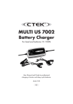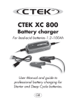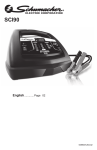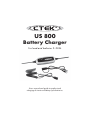
1
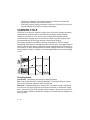
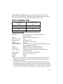
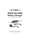
US 800
Battery Charger
For lead-acid batteries 2–32Ah
Users manual and guide to professional
charging of starter and deep cycle batteries.
INTRODUCTION
US 800 is a switch mode charger with pulse maintenance and is a part of a series of
professional battery chargers from CTEK SWEDEN AB. These chargers represent the
latest technology within battery charging. A US 800 gives the battery maximum life. Read
this User’s Manual and follow the instructions carefully before you start to use the
charger.
IMPORTANT SAFETY INSTRUCTIONS
California Proposition 65
WARNING: This product contains chemical known to the state of California to cause
cancer or reproductive toxicity.
Check the charger cabling before use. Make sure there are no cracks in the cabling or in
the protective covering. A charger with damaged cables may not be used.
1. SAVE THESE INSTRUCTIONS – This manual contains
2.
3.
4.
5.
6.
7.
8.
9.
10.
2 • US
important safety and operating instructions for the US 800 battery charger.
When charging, batteries can emit explosive gases, therefore it is essential to
SUHYHQWÀDPHVDQGVSDUNV7KHFKDUJHULVGHVLJQHGIRUFKDUJLQJOHDGDFLGEDWWHUies from 2 to 32Ah. Do not use for any other purpose.
Always provide good ventilation when charging.
Use of an attachment not recommended or sold by CTEK may result in a risk of
¿UHHOHFWULFVKRFNRUVHULRXVLQMXU\WRSHUVRQV
To reduce risk of damage to electric plug and cord, pull by the plug rather than by
the cord when disconnecting charger.
An extension cord should not be used unless absolutely necessary. Use
RIDQLPSURSHUH[WHQVLRQFRUGFRXOGUHVXOWLQDULVNRI¿UHDQGHOHFWULFVKRFN,I
extension cord must be used, make sure that: a) Pins on plug of extension cord are
the same number, size and shape as those of plug on charger; b) Extension cord is
properly wired and in good electrical condition; and c) Wire size is large enough for
$&DPSHUHUDWLQJDVVSHFL¿HGLQ³WHFKQLFDOGDWD´
Do not operate charger with a damaged cord or plug - return the charger to the
place where purchased.
Never operate the charger if it has received a sharp blow, been dropped or
RWKHUZLVHGDPDJHGLQDQ\ZD\WDNHLWWRDTXDOL¿HGVHUYLFHPDQ
'RQRWGLVDVVHPEOHWKHFKDUJHUWDNHLWWRDTXDOL¿HGVHUYLFHPDQZKHQVHUYLFHRU
repair is required. Incorrect reassembly may result in a risk of electrical shock or
¿UH
To reduce risk of electric shock, unplug charger from AC outlet before attempting
any maintenance or cleaning. Turning off controls will not reduce the risk.
11. WARNING - RISK OF EXPLOSIVE GASES
a) BATTERIES GENERATE EXPLOSIVE GASES
DURING NORMAL BATTERY OPERATION.
FOR THIS REASON, IT IS OF THE UTMOST
IMPORTANCE THAT EACH TIME BEFORE
USING YOUR CHARGER, YOU READ THIS
MANUAL AND FOLLOW THE INSTRUCTIONS
CAREFULLY.
a) Follow these instructions and those published by the battery manufacturer and the
manufacturer of any equipment you intend to use in vicinity of battery.
12. PERSONAL PRECAUTIONS
a) Some one should be within voice range or close enough to come to your aid when
you work near a lead-acid battery.
b) Have plenty of fresh water and soap nearby in case battery acid contacts skin,
clothing or eyes.
c) Always wear complete eye protection and clothing protection. Avoid touching eyes
while working near battery.
d) If battery acid contacts skin or clothing, wash immediately with soap and water.
,IDFLGHQWHUVH\HLPPHGLDWHO\ÀRRGH\HZLWKUXQQLQJFROGZDWHUIRUDWOHDVW
10 minutes and get medical attention immediately.
e) 1(9(5VPRNHRUDOORZDVSDUNRUÀDPHLQYLFLQLW\RIEDWWHU\RUHQJLQH
f) Be extra cautious to reduce risk of dropping a metal tool onto battery. It might spark
or short-circuit battery or other electrical part that may cause explosion.
g) Remove personal metal items such as rings, bracelets, necklaces, and watches
when working with lead-acid battery. A lead-acid battery can produce a
short-circuit current high enough to weld a ring or the like to metal, causing a
severe burn.
h) Use charger for charging a LEAD-ACID battery only. Do not use battery charger for
dry-cell batteries that are commonly used with home appliances. These batteries
PD\EXUVWDQGFDXVHLQMXU\WRSHUVRQVDQGGDPDJHWRSURSHUW\
i) Never charge a frozen battery.
US • 3
13. PREPARING TO CHARGE
a) If necessary to remove battery from vehicle to charge, always remove grounded
WHUPLQDOIURPEDWWHU\¿UVW0DNHVXUHDOODFFHVVRULHVLQWKHYHKLFOHDUHRIIVRDV
not to cause an arc.
b) Be sure area around battery is well ventilated while battery is being charged. Gas
can be forcefully blown away by fanning the area with a piece of cardboard or other
non-metallic material.
c) Clean battery terminals. Be careful to keep corrosion from coming in contact with
eyes.
d) $GGGLVWLOOHGZDWHULQHDFKFHOOXQWLOEDWWHU\DFLGUHDFKHVOHYHOVSHFL¿HGE\EDWWHU\
PDQXIDFWXUHU7KLVKHOSVWRSXUJHH[FHVVLYHJDVIURPFHOOV'RQRWRYHU¿OO)RU
a battery without cell caps, such as valve regulated lead acid batteries, carefully
follow manufacturer’s recharging instruction.
e) 6WXG\EDWWHU\PDQXIDFWXUHU¶VVSHFL¿FSUHFDXWLRQVZKLOHFKDUJLQJDQGUHFRPmended rates of charge.
f) Determine voltage of battery by referring to car owner’s manual and make sure that
the output voltage selector switch is set at correct voltage.
14. CHARGER LOCATION
a) Locate charger as far away from the battery as battery charger cables permit.
b) Never place charger directly above battery being charged; gases from battery will
corrode and damage charger.
c) Never allow battery acid to drip on charger.
d) Do not operate charger in a closed-in area or restrict ventilation in any way.
e) Do not set a battery on top of charger.
15. DC CONNECTION PRECAUTIONS
a) Connect and disconnect DC output clips only after setting any charger switches to
off position and removing AC cord from electric outlet. Never allow clips to touch
each other.
b) Attach clips to battery and chassis as indicated in 16(e), 16(f), 17(b) and
through 17(d).
4 • US
16. FOLLOW THESE STEPS WHEN BATTERY
IS INSTALLED IN VEHICLE. A SPARK
NEAR BATTERY MAY CAUSE BATTERY
EXPLOSION. TO REDUCE RISK OF A SPARK
NEAR BATTERY:
a) Position AC and DC cord in a safe position to reduce risk of damage by hood, door
or moving engine part.
b) 6WD\FOHDURIIDQEODGHVEHOWVSXOOH\VDQGRWKHUSDUWVWKDWFDQFDXVHLQMXU\WR
persons.
c) Check polarity of battery terminals. POSITIVE (POS, P, +) battery post usually has
larger diameter than NEGATIVE (NEG, N, -) post.
d) Determine which post of battery is grounded (connected) to the chassis. If negative
post is grounded to the chassis (as in most vehicles) see (e). If positive post is
grounded to the chassis, see (f).
e) Negative-grounded vehicle
Charger connection.
1. Connect positive charger clip (red) to positive battery terminal.
2. Connect negative charger clip (black) to a good metal engine ground away from
the battery. Do no connect clip to fuel lines or sheet-metal body parts.
3. Connect the AC cord to the socket. The red alarm indication light will indicate a
battery which is connected to reverse polarity.
f) Positive grounded vehicle
Charger connection.
1. Connect negative charger clip (black) to negative battery terminal.
2. Connect positive charger clip (red) to a good metal engine ground away from the
battery. Do no connect clip to fuel lines or sheet-metal body parts.
3. Connect the AC cord to the socket. The red alarm indication light will indicate a
battery which is connected to reverse polarity.
g) When disconnecting charger, disconnect AC cord, remove clip from vehicle
chassis, and then remove clip from battery terminal.
h) See charge information below.
US • 5
17. FOLLOW THESE STEPS WHEN BATTERY
IS OUTSIDE VEHICLE. A SPARK NEAR
BATTERY MAY CAUSE BATTERY
EXPLOSION. TO REDUCE RISK OF A SPARK
NEAR BATTERY:
a) Check polarity of battery terminals. POSITIVE (POS, P, +) battery post usually has
larger diameter than NEGATIVE (NEG, N, -) post.
b) Connect POSITIVE (RED) charger clip to POSITIVE (POS, P, +) battery post.
c) Connect NEGATIVE (Black) charger clip to NEGATIVE (NEG, N, -) battery post.
The red alarm indication light will indicate a battery, which is connected to reverse
polarity.
d) Connect charger’s AC cord to socket.
e) 'RQRWIDFHWKHEDWWHU\ZKHQPDNLQJWKH¿QDOFRQQHFWLRQ
f) When disconnecting charger, disconnect in reverse sequence from connecting
procedure. See charge information below.
The battery charger must be connected to the battery according to the instructions
above.
IMPORTANT SAFETY INFORMATION!
The US 800 cannot be used to restore a fully worn out battery. If the US 800 does not
switch to maintenance charge after three days (green light illuminated), there is a fault.
Possible causes:
• The battery is probably worn out and should be replaced.
• Some large antimony batteries may behave differently and can allow the US 800 to
charge the battery for too long, which can lead to overcharging. See caution!
• ,ISRZHUFRQVXPHUVOLNH¿WWHGDODUPVDQGQDYLJDWLRQFRPSXWHUVDUHFRQQHFWHGWRWKH
battery, the charging process takes longer and this can also overcharge the battery.
• $VXOSKDWHGEDWWHU\ZLOORQO\DFFHSWFXUUHQWZLWKGLI¿FXOW\DQGFRQVHTXHQWO\WKH
charging process takes a particularly long time. A worn out battery cannot be fully
charged. Therefore you should always check whether the charger has been switched to
maintenance charge before you leave it turned on or unobserved for any length of time.
Caution: If the US 800 does not switch to maintenance mode after three days, it has
to be manually disconnected. If the set has been switched to maintenance charge, then
everything is in order.
6 • US
Note: A battery that hasn’t changed to maintenance charge after three days is most likely
worn out and needs to be replaced. All other batteries can be maintained for a very long
time.
BATTERY TYPES
The following recommendations should only be considered as guidelines. In the event of
uncertainty always refer to the battery manufacturer’s recommendations.
US 800 is suitable for charging all types of 12V lead-acid batteries: open batteries, MF,
Wet, AGM and most GEL-batteries. Battery sizes from 2 to 32Ah. The charger can
maintain batteries up to 100Ah.
CHARGING
The battery charger must be connected to the battery according to
the instructions above.
Starting the charging process:
1. Once you have established that the battery cable has been correctly connected you
can start the charging process. To do so, insert the charger plug into the AC socket.
2. Now either the charge indicator
or the maintenance charge indicator
lights up.
When the maintenance charge indicator lights up, the battery is fully charged. If the
battery voltage drops, the charger sends a pulse to the battery. The length of the pulse
depends on how much charge the battery has lost. The US 800 may be connected for
months at a time. However it is recommended to monitor batteries on charge.
3. The red alarm indication light will indicate a battery, which is connected to reverse
polarity.
4. If nothing happens: If no indicator is illuminated, the connection to the battery or the
chassis could be faulty, or the battery could be defective. If the charging process
has not started, this could be due to the fact that the power socket is not supplying a
current.
5. The charging process can be interrupted at any time. In addition pull the plug of the
charger out of the power socket. Always remove the plug of the charger from the
power socket before disconnecting the battery cable. If you interrupt the charging
SURFHVVRIDEDWWHU\¿WWHGLQDYHKLFOHWKHEDWWHU\FDEOHPXVWDOZD\VEH¿UVWGLVFRQnected from the chassis and then from the other battery cable.
6. If the indicators for charge
and maintenance charge DUHÀDVKLQJDOWHUQDWHO\
this may have the following causes:
• Interruption of the charging process because of a lost connection or because the
battery is not conducting.
US • 7
• 7KHEDWWHU\LVVXOSKDWHG,IWKHLQGLFDWRUVÀDVKHVIRUPRUHWKDQPLQXWHVWKH
battery may be defective and should be replaced.
• ,IWKHÀDVKLQJVLJQDOLVÀDVKLQJDWLQWHUYDOVRIPRUHWKDQVHFRQGVWKHQWKHUHLVD
high self discharge of the battery, indicating a bad battery.
CHARGING CYCLE
US 800 has a four step fully automatic charging cycle. At the start of charging the battery
charger delivers maximum current to the battery and the battery voltage increases
constantly to a set level of 14.4V. At this point the voltage will be regulated and kept
constant while the charging current is successively lowered. Once the charging current
has dropped below 0.4A the charger switches to maintenance charging.
If the battery is loaded and the battery’s terminal voltage drops to 12.9V the charger
automatically switches back to the beginning of the four step cycle. The charger requires a
reverse voltage from the battery of at least 6V to start the charging cycle, this means that
if the battery is so deeply discharged that the terminal voltage is lower than 6V the charger
cannot charge the battery in question. A normal discharged battery has a terminal voltage
of 10.5V.
Charging phases:
Desulphation - Desulphation with pulsing for sulphated batteries.
Bulk - Main charge when 80% of charging takes place. The charger delivers a constant
current until the terminal voltage has risen to the set level.
Absorption - Complete charge up to virtually 100%. The terminal voltage is maintained
at the set level. During this phase the current drops successively so the terminal voltage
does not become too high. If the absorption phase has been in progress for more than 18
hours the charger switches to maintenance charging. This function prevents damage if the
battery is faulty.
8 • US
Pulse - Maintenance charging. Charging level varies between 95% and 100%. The
battery receives a pulse when the voltage drops. Keeps the battery in perfect condition
when it is not used. The charger can be connected for months at a time.
BULK CHARGING TIME
Battery capacity
(Ah)
2
8
20
32
Time to ~80% charge
(h)
1.5
6
20
36
SPECIFICATION
Voltage AC
Current
Back current drain*
Charging voltage
Ripple**
Charging current
Ambient temperature
Cooling
Charge cycle
Type of batteries
Battery capacity
Dimensions
Insulation
Weight
85–125VAC, 50–60Hz. Output power is reduced at
lower input voltage.
130mA rms (at full charging current)
<1mA
14.4V, Nominal: 12V
Max 50mV rms, max 0.05A rms.
0.8A max.
-20°C to +50°C (-4°F to +122°F). Automatic reduction of power
at increased ambient temperature.
Natural convection. Do not cover the charger.
US 800 is a four-step fully automatic charger.
All types of 12V lead-acid batteries (Wet, Maintenance Free,
AGM and most GEL).
2 to 32Ah, up to 100Ah for maintenance.
5½ x 2 x 1½ inches (L x W x H)
Raintight.
0.7 lbs
*) The back current drain is the current that the charger uses from the battery when the
wall plug is not connected. The reverse current of the US 800 is very low and corresponds to 1Ah per month.
**) The ripple wave describes how many disturbances are exhibited by current and voltage. A rippled voltage can cause damage to other equipment connected to the battery.
The US 800 supplies voltage and current with very low voltage rippling. This increases
the life of the battery and ensures that equipment connected to it will not be damaged.
US • 9
BATTERY CABLES
US 800 is equipped with a set of battery cables with battery terminal clips and one set of
battery cables with eyelet terminals.
Connecting the provided cables with eyelet terminals
Make sure that the cable is not pinched or in contact with warm surfaces or sharp edges.
When the cable is mounted on the battery, it should not be connected to the charger.
Connect the eyelet terminals to the battery's poles - the red cable to the positive pole and
the black cable to the negative pole. After this, the quick connector can be connected.
OVERHEATING PROTECTION
The US 800 is equipped with overheating protection. In high ambient temperatures the
output power is reduced. Do not cover the charger.
MAINTENANCE
The US 800 is maintenance-free. The charger must not be opened; doing so will invalidate
the warranty. If the power cable is damaged it must be replaced by CTEK or its authorized
representative. The charger casing can be cleaned using a damp cloth and mild cleaning
agent. Remove the plug from the power socket before cleaning.
LIMITED WARRANTY
CTEK SWEDEN AB, Rostugnsv. 3, SE-776 70 VIKMANSHYTTAN, SWEDEN issues
this limited warranty to the original purchaser of this product. This limited warranty is not
transferable. CTEK SWEDEN AB warrants this unit for 5 years from the date of purchase
against defect workmanship or material. It is the obligation of the purchaser to forward
the unit together with proof of purchase to the manufacturer or its representative with
transportation cost prepaid. This warranty is void if the unit is abused, handled carelessly
or repaired by anyone other than CTEK SWEDEN AB or its authorized representative.
CTEK SWEDEN AB makes no warranty other than this limited warranty and expressly
excludes any implied warranty including any warranty for consequential damages. This
is the only expressed limited warranty and CTEK SWEDEN AB neither assumes nor
authorizes anyone to assume or make any other obligation towards the product other than
this limited warranty.
CTEK SWEDEN AB
Rostugnsvägen 3
SE-776 70 VIKMANSHYTTAN
SWEDEN
Fax: + 46 225 307 93
www.ctek.com
10 • US