1
Troubleshooting
Guide
HP StorageWorks
HSG60 and HSG80 Array
Controller and Array Controller
Software
Product Version: 8.8-1
Third Edition (March 2005)
Part Number: EK-G80TS-SA.C01
This guide provides troubleshooting instructions for HSG60 and HSG80 array controllers
running Array Controller Software (ACS) Versions 8.8L, 8.8F, 8.8G, 8.8P, and 8.8S. This
guide contains information on various utilities, software templates, and event reporting codes.
© Copyright 2000–2005 Hewlett-Packard Development Company, L.P.
Hewlett-Packard Company makes no warranty of any kind with regard to this material, including, but not limited
to, the implied warranties of merchantability and fitness for a particular purpose. Hewlett-Packard shall not be
liable for errors contained herein or for incidental or consequential damages in connection with the furnishing,
performance, or use of this material.
This document contains proprietary information, which is protected by copyright. No part of this document may be
photocopied, reproduced, or translated into another language without the prior written consent of Hewlett-Packard.
The information contained in this document is subject to change without notice. The only warranties for HP products
and services are set forth in the express warranty statements accompanying such products and services. Nothing
herein should be construed as constituting an additional warranty. HP shall not be liable for technical or editorial
errors or omissions contained herein.
Compaq Computer Corporation is a wholly-owned subsidiary of Hewlett-Packard Company.
Intel® and Celeron® are U.S. registered trademarks of Intel Corporation.
UNIX® is a registered trademark of The Open Group.
Hewlett-Packard Company shall not be liable for technical or editorial errors or omissions contained herein. The
information is provided “as is” without warranty of any kind and is subject to change without notice. The warranties
for Hewlett-Packard Company products are set forth in the express limited warranty statements for such products.
Nothing herein should be construed as constituting an additional warranty.
HSG60 and HSG80 Array Controller and Array Controller Software Troubleshooting Guide
Third Edition (March 2005)
Part Number: EK-G80TS-SA.C01
contents
Contents
About this Guide. . . . . . . . . . . . . . . . . . . . . . . . . . . . . . . . . . . . . . . . . . . . . . . . . . .11
Overview. . . . . . . . . . . . . . . . . . . . . . . . . . . . . . . . . . . . . . . . . . . . . . . . . . . . . . . . . . . . . . . . . 11
Intended audience. . . . . . . . . . . . . . . . . . . . . . . . . . . . . . . . . . . . . . . . . . . . . . . . . . . . . . . 12
Prerequisites . . . . . . . . . . . . . . . . . . . . . . . . . . . . . . . . . . . . . . . . . . . . . . . . . . . . . . . . . . . 12
Related documentation. . . . . . . . . . . . . . . . . . . . . . . . . . . . . . . . . . . . . . . . . . . . . . . . . . . 12
Conventions . . . . . . . . . . . . . . . . . . . . . . . . . . . . . . . . . . . . . . . . . . . . . . . . . . . . . . . . . . . . . . 15
Document conventions. . . . . . . . . . . . . . . . . . . . . . . . . . . . . . . . . . . . . . . . . . . . . . . . . . . 15
Text symbols . . . . . . . . . . . . . . . . . . . . . . . . . . . . . . . . . . . . . . . . . . . . . . . . . . . . . . . . . . 15
Equipment symbols . . . . . . . . . . . . . . . . . . . . . . . . . . . . . . . . . . . . . . . . . . . . . . . . . . . . . 16
Rack stability . . . . . . . . . . . . . . . . . . . . . . . . . . . . . . . . . . . . . . . . . . . . . . . . . . . . . . . . . . . . . 17
Getting help . . . . . . . . . . . . . . . . . . . . . . . . . . . . . . . . . . . . . . . . . . . . . . . . . . . . . . . . . . . . . . 18
HP technical support . . . . . . . . . . . . . . . . . . . . . . . . . . . . . . . . . . . . . . . . . . . . . . . . . . . . 18
HP storage website. . . . . . . . . . . . . . . . . . . . . . . . . . . . . . . . . . . . . . . . . . . . . . . . . . . . . . 18
HP authorized reseller . . . . . . . . . . . . . . . . . . . . . . . . . . . . . . . . . . . . . . . . . . . . . . . . . . . 18
1
Troubleshooting Information . . . . . . . . . . . . . . . . . . . . . . . . . . . . . . . . . . . . . . . . . .19
Typical installation problem identification checklist and troubleshooting guidelines . . . . . . 20
Significant event reporting . . . . . . . . . . . . . . . . . . . . . . . . . . . . . . . . . . . . . . . . . . . . . . . . . . . 31
Reporting events that cause controller operation to halt . . . . . . . . . . . . . . . . . . . . . . . . . 31
Flashing OCP pattern display reporting . . . . . . . . . . . . . . . . . . . . . . . . . . . . . . . . . . 32
Solid OCP pattern display reporting . . . . . . . . . . . . . . . . . . . . . . . . . . . . . . . . . . . . . 34
Last failure reporting . . . . . . . . . . . . . . . . . . . . . . . . . . . . . . . . . . . . . . . . . . . . . . . . . 39
Reporting events that allow controller operation to continue . . . . . . . . . . . . . . . . . . . . . 40
Spontaneous Event log . . . . . . . . . . . . . . . . . . . . . . . . . . . . . . . . . . . . . . . . . . . . . . . 40
CLI Event reporting. . . . . . . . . . . . . . . . . . . . . . . . . . . . . . . . . . . . . . . . . . . . . . . . . . 41
Running the controller diagnostic test . . . . . . . . . . . . . . . . . . . . . . . . . . . . . . . . . . . . . . . 41
ECB charging diagnostics . . . . . . . . . . . . . . . . . . . . . . . . . . . . . . . . . . . . . . . . . . . . . 42
Battery hysteresis. . . . . . . . . . . . . . . . . . . . . . . . . . . . . . . . . . . . . . . . . . . . . . . . . . . . 42
UPS used for backup power . . . . . . . . . . . . . . . . . . . . . . . . . . . . . . . . . . . . . . . . . . . 43
HSG60 and HSG80 Array Controller and Array Controller Software Troubleshooting Guide
3
Contents
Caching techniques . . . . . . . . . . . . . . . . . . . . . . . . . . . . . . . . . . . . . . . . . . . . . . . . . . . . .
Read caching . . . . . . . . . . . . . . . . . . . . . . . . . . . . . . . . . . . . . . . . . . . . . . . . . . . . . . .
Read-ahead caching. . . . . . . . . . . . . . . . . . . . . . . . . . . . . . . . . . . . . . . . . . . . . . . . . .
Write-through caching. . . . . . . . . . . . . . . . . . . . . . . . . . . . . . . . . . . . . . . . . . . . . . . .
Writeback caching . . . . . . . . . . . . . . . . . . . . . . . . . . . . . . . . . . . . . . . . . . . . . . . . . . .
Fault-tolerance for writeback caching . . . . . . . . . . . . . . . . . . . . . . . . . . . . . . . . . . . .
Nonvolatile memory . . . . . . . . . . . . . . . . . . . . . . . . . . . . . . . . . . . . . . . . . . . . . .
Cache policies resulting from cache module failures . . . . . . . . . . . . . . . . . . . . .
Dual external cache battery failures . . . . . . . . . . . . . . . . . . . . . . . . . . . . . . . . . .
Enabling mirrored writeback cache. . . . . . . . . . . . . . . . . . . . . . . . . . . . . . . . . . . . . .
Device Discovery Error report . . . . . . . . . . . . . . . . . . . . . . . . . . . . . . . . . . . . . . . . . . . . .
SHOW ELEVATION report . . . . . . . . . . . . . . . . . . . . . . . . . . . . . . . . . . . . . . . . . . . . . . .
44
44
44
45
45
45
46
47
53
53
53
56
2
Utilities and Exercisers . . . . . . . . . . . . . . . . . . . . . . . . . . . . . . . . . . . . . . . . . . . . . .67
Fault Management Utility (FMU) . . . . . . . . . . . . . . . . . . . . . . . . . . . . . . . . . . . . . . . . . . . . . 68
Displaying last failure entries. . . . . . . . . . . . . . . . . . . . . . . . . . . . . . . . . . . . . . . . . . . . . . 68
Translating event codes . . . . . . . . . . . . . . . . . . . . . . . . . . . . . . . . . . . . . . . . . . . . . . . . . . 70
Controlling the display of significant events and failures . . . . . . . . . . . . . . . . . . . . . . . . 71
SHOW LAST ALL command. . . . . . . . . . . . . . . . . . . . . . . . . . . . . . . . . . . . . . . . . . . 74
SHOW RESERVATION command. . . . . . . . . . . . . . . . . . . . . . . . . . . . . . . . . . . . . . . . . . 75
Command variants . . . . . . . . . . . . . . . . . . . . . . . . . . . . . . . . . . . . . . . . . . . . . . . 75
CLEAR RESERVATION command . . . . . . . . . . . . . . . . . . . . . . . . . . . . . . . . . . . . . . . . 77
Device Information and Error Utilities . . . . . . . . . . . . . . . . . . . . . . . . . . . . . . . . . . . . . . 78
SHOW DEVICE_INFORMATION command . . . . . . . . . . . . . . . . . . . . . . . . . . . . . . 78
. . . . . . . . . . . . . . . . . . . . . . . . . . . . . . . . . . . . . . . . . . . . . . . . . . . . . . . . . . . . . . . . . . 80
SHOW DEVICE_ERRORS and CLEAR DEVICE_ERRORS unit command . . 84
SHOW DEVICE_ERRORS command. . . . . . . . . . . . . . . . . . . . . . . . . . . . . . . . 84
Interpreting Event log fields . . . . . . . . . . . . . . . . . . . . . . . . . . . . . . . . . . . . . . . . 85
Common event descriptions . . . . . . . . . . . . . . . . . . . . . . . . . . . . . . . . . . . . . . . . 87
CLEAR DEVICE_ERRORS unit command . . . . . . . . . . . . . . . . . . . . . . . . . . . . 88
Video Terminal Display (VTDPY) utility . . . . . . . . . . . . . . . . . . . . . . . . . . . . . . . . . . . . . . . . 89
VTDPY Restrictions . . . . . . . . . . . . . . . . . . . . . . . . . . . . . . . . . . . . . . . . . . . . . . . . . . . . . 89
Running VTDPY. . . . . . . . . . . . . . . . . . . . . . . . . . . . . . . . . . . . . . . . . . . . . . . . . . . . . . . . 89
VTDPY help . . . . . . . . . . . . . . . . . . . . . . . . . . . . . . . . . . . . . . . . . . . . . . . . . . . . . . . . . . . 91
VTDPY screens. . . . . . . . . . . . . . . . . . . . . . . . . . . . . . . . . . . . . . . . . . . . . . . . . . . . . . . . . 92
Display Default screen. . . . . . . . . . . . . . . . . . . . . . . . . . . . . . . . . . . . . . . . . . . . . . . . 92
Controller Status screen. . . . . . . . . . . . . . . . . . . . . . . . . . . . . . . . . . . . . . . . . . . . . . . 93
Cache Performance screen. . . . . . . . . . . . . . . . . . . . . . . . . . . . . . . . . . . . . . . . . . . . . 95
Device Performance screen . . . . . . . . . . . . . . . . . . . . . . . . . . . . . . . . . . . . . . . . . . . . 96
4
HSG60 and HSG80 Array Controller and Array Controller Software Troubleshooting Guide
Contents
Host Ports Statistics screen . . . . . . . . . . . . . . . . . . . . . . . . . . . . . . . . . . . . . . . . . . . . 98
Resource Statistics screen . . . . . . . . . . . . . . . . . . . . . . . . . . . . . . . . . . . . . . . . . . . . 100
Remote Status screen. . . . . . . . . . . . . . . . . . . . . . . . . . . . . . . . . . . . . . . . . . . . . . . . 102
Interpreting VTDPY screen information. . . . . . . . . . . . . . . . . . . . . . . . . . . . . . . . . . . . . 102
Screen header. . . . . . . . . . . . . . . . . . . . . . . . . . . . . . . . . . . . . . . . . . . . . . . . . . . . . . 103
Common data fields. . . . . . . . . . . . . . . . . . . . . . . . . . . . . . . . . . . . . . . . . . . . . . . . . 104
Unit Performance data fields . . . . . . . . . . . . . . . . . . . . . . . . . . . . . . . . . . . . . . . . . . 105
Device Performance data fields. . . . . . . . . . . . . . . . . . . . . . . . . . . . . . . . . . . . . . . . 108
Device Port Performance data fields . . . . . . . . . . . . . . . . . . . . . . . . . . . . . . . . . . . . 109
Host port configuration . . . . . . . . . . . . . . . . . . . . . . . . . . . . . . . . . . . . . . . . . . . . . . 110
TACHYON chip status . . . . . . . . . . . . . . . . . . . . . . . . . . . . . . . . . . . . . . . . . . . . . . 112
Runtime Status of Remote Copy Sets screen . . . . . . . . . . . . . . . . . . . . . . . . . . . . . 113
Device port configuration . . . . . . . . . . . . . . . . . . . . . . . . . . . . . . . . . . . . . . . . . . . . 114
Controller and processor utilization . . . . . . . . . . . . . . . . . . . . . . . . . . . . . . . . . . . . 115
Resource performance statistics . . . . . . . . . . . . . . . . . . . . . . . . . . . . . . . . . . . . . . . 117
Disk Inline Exerciser (DILX) . . . . . . . . . . . . . . . . . . . . . . . . . . . . . . . . . . . . . . . . . . . . . . . . 119
Checking for unit problems . . . . . . . . . . . . . . . . . . . . . . . . . . . . . . . . . . . . . . . . . . . . . . 119
Finding a unit in the subsystem . . . . . . . . . . . . . . . . . . . . . . . . . . . . . . . . . . . . . . . . 119
Testing the read capability of a unit . . . . . . . . . . . . . . . . . . . . . . . . . . . . . . . . . . . . 119
Testing the read and write capabilities of a unit . . . . . . . . . . . . . . . . . . . . . . . . . . . 121
DILX error codes . . . . . . . . . . . . . . . . . . . . . . . . . . . . . . . . . . . . . . . . . . . . . . . . . . . . . . 124
Format and device code load utility (HSUTIL) . . . . . . . . . . . . . . . . . . . . . . . . . . . . . . . . . . 126
Configuration (CONFIG) utility. . . . . . . . . . . . . . . . . . . . . . . . . . . . . . . . . . . . . . . . . . . . . . 128
Code Load and Code Patch (CLCP) utility . . . . . . . . . . . . . . . . . . . . . . . . . . . . . . . . . . . . . 129
CLONE utility. . . . . . . . . . . . . . . . . . . . . . . . . . . . . . . . . . . . . . . . . . . . . . . . . . . . . . . . . . . . 131
Field Replacement Utility (FRUTIL) . . . . . . . . . . . . . . . . . . . . . . . . . . . . . . . . . . . . . . . . . . 132
Change Volume Serial Number (CHVSN) utility . . . . . . . . . . . . . . . . . . . . . . . . . . . . . . . . . 133
3
Event Reporting Templates. . . . . . . . . . . . . . . . . . . . . . . . . . . . . . . . . . . . . . . . . . .135
Passthrough Device Reset Event Sense Data Response template . . . . . . . . . . . . . . . . . . . . 137
Last Failure Event Sense Data Response template (Template 01) . . . . . . . . . . . . . . . . . . . . 138
Multiple-Bus Failover Event Sense Data Response template (Template 04). . . . . . . . . . . . 140
Failover Event Sense Data Response template (Template 05). . . . . . . . . . . . . . . . . . . . . . . 142
Device Discovery Error Sense Data Response template (Template 06) . . . . . . . . . . . . . . . 144
Nonvolatile Parameter Memory Component Event Sense Data Response template
(Template 11) . . . . . . . . . . . . . . . . . . . . . . . . . . . . . . . . . . . . . . . . . . . . . . . . . . . . . . . . . . . . 145
Backup Battery Failure Event Sense Data Response template (Template 12). . . . . . . . . . . 147
Subsystem Built-In Self-Test Failure Event Sense Data Response template (Template 13) 149
Memory System Failure Event Sense Data Response template (Template 14) . . . . . . . . . . 151
HSG60 and HSG80 Array Controller and Array Controller Software Troubleshooting Guide
5
Contents
Device Services Nontransfer Error Event Sense Data Response template (Template 41). .
Disk Transfer Error Event Sense Data Response template (Template 51). . . . . . . . . . . . . .
Data Replication Manager Services Event Sense Response template (Template 90) . . . . .
Connection Table Full Event Error template (Template A0) . . . . . . . . . . . . . . . . . . . . . . . .
153
155
157
159
4
ASC, ASCQ, Repair Action, and Component Identifier Codes . . . . . . . . . . . . . . . . .161
Vendor-specific SCSI ASC and ASCQ codes . . . . . . . . . . . . . . . . . . . . . . . . . . . . . . . . . . . 162
Recommended Repair Action Codes . . . . . . . . . . . . . . . . . . . . . . . . . . . . . . . . . . . . . . . . . . 167
Component ID Codes . . . . . . . . . . . . . . . . . . . . . . . . . . . . . . . . . . . . . . . . . . . . . . . . . . . . . . 175
5
Instance Codes . . . . . . . . . . . . . . . . . . . . . . . . . . . . . . . . . . . . . . . . . . . . . . . . . . .177
Instance Code structure. . . . . . . . . . . . . . . . . . . . . . . . . . . . . . . . . . . . . . . . . . . . . . . . . . . . . 178
Instance Code format . . . . . . . . . . . . . . . . . . . . . . . . . . . . . . . . . . . . . . . . . . . . . . . . . . . . . . 179
Notification and recovery threshold. . . . . . . . . . . . . . . . . . . . . . . . . . . . . . . . . . . . . . . . 179
Repair action . . . . . . . . . . . . . . . . . . . . . . . . . . . . . . . . . . . . . . . . . . . . . . . . . . . . . . . . . 180
Event number . . . . . . . . . . . . . . . . . . . . . . . . . . . . . . . . . . . . . . . . . . . . . . . . . . . . . . . . . 180
Component ID . . . . . . . . . . . . . . . . . . . . . . . . . . . . . . . . . . . . . . . . . . . . . . . . . . . . . . . . 180
6
Last Failure Codes . . . . . . . . . . . . . . . . . . . . . . . . . . . . . . . . . . . . . . . . . . . . . . . . .211
Last Failure Code structure. . . . . . . . . . . . . . . . . . . . . . . . . . . . . . . . . . . . . . . . . . . . . . . . . . 212
Last Failure Code format . . . . . . . . . . . . . . . . . . . . . . . . . . . . . . . . . . . . . . . . . . . . . . . . . . . 213
Parameter Count. . . . . . . . . . . . . . . . . . . . . . . . . . . . . . . . . . . . . . . . . . . . . . . . . . . . . . . 213
Restart Code . . . . . . . . . . . . . . . . . . . . . . . . . . . . . . . . . . . . . . . . . . . . . . . . . . . . . . . . . . 213
Hardware and software flag . . . . . . . . . . . . . . . . . . . . . . . . . . . . . . . . . . . . . . . . . . . . . . 214
Repair Action Code . . . . . . . . . . . . . . . . . . . . . . . . . . . . . . . . . . . . . . . . . . . . . . . . . . . . 214
Error Number . . . . . . . . . . . . . . . . . . . . . . . . . . . . . . . . . . . . . . . . . . . . . . . . . . . . . . . . . 214
Component ID Code . . . . . . . . . . . . . . . . . . . . . . . . . . . . . . . . . . . . . . . . . . . . . . . . . . . 214
Last Failure and Repair Action Codes . . . . . . . . . . . . . . . . . . . . . . . . . . . . . . . . . . . . . . 214
7
Alternative Controller Operations . . . . . . . . . . . . . . . . . . . . . . . . . . . . . . . . . . . . .269
Handling host-configured units in error . . . . . . . . . . . . . . . . . . . . . . . . . . . . . . . . . . . . . . . . 270
Setting SCSI Fairness . . . . . . . . . . . . . . . . . . . . . . . . . . . . . . . . . . . . . . . . . . . . . . . . . . . . . . 272
Glossary. . . . . . . . . . . . . . . . . . . . . . . . . . . . . . . . . . . . . . . . . . . . . . . . . . . . . . . .275
Index . . . . . . . . . . . . . . . . . . . . . . . . . . . . . . . . . . . . . . . . . . . . . . . . . . . . . . . . . .303
6
HSG60 and HSG80 Array Controller and Array Controller Software Troubleshooting Guide
Contents
Figures
1 OCP pattern display showing %FLL formatting . . . . . . . . . . . . . . . . . . . . . . . . . . . . . . . 34
2 Sample Last Failure report . . . . . . . . . . . . . . . . . . . . . . . . . . . . . . . . . . . . . . . . . . . . . . . . 39
3 Sample Spontaneous Event logs showing %EVL formatting . . . . . . . . . . . . . . . . . . . . . 40
4 Sample CLI Event report showing %CER formatting. . . . . . . . . . . . . . . . . . . . . . . . . . . 41
5 SHOW THIS CLI sample screen display. . . . . . . . . . . . . . . . . . . . . . . . . . . . . . . . . . . . . 43
6 Sample Device Discovery Error Report. . . . . . . . . . . . . . . . . . . . . . . . . . . . . . . . . . . . . . 54
7 Sample last failure entry. . . . . . . . . . . . . . . . . . . . . . . . . . . . . . . . . . . . . . . . . . . . . . . . . . 69
8 FMU translation of a Last Failure Code and an Instance Code Sample . . . . . . . . . . . . . 71
9 SHOW RESERVATION sample output (Microsoft® Windows® 2003 32-bit) . . . . . . . 76
10 SHOW RESERVATION Sample Output (HP Tru64 UNIX) . . . . . . . . . . . . . . . . . . . . . . 77
11 SHOW DEVICE_INFO Dxxxx sample output . . . . . . . . . . . . . . . . . . . . . . . . . . . . . . . . 78
12 SHOW DEVICE_INFO ALL sample output. . . . . . . . . . . . . . . . . . . . . . . . . . . . . . . . . . . 79
13 SHOW DEVICE_ERRORS sample output . . . . . . . . . . . . . . . . . . . . . . . . . . . . . . . . . . . . 84
14 Event log interpretation . . . . . . . . . . . . . . . . . . . . . . . . . . . . . . . . . . . . . . . . . . . . . . . . . . 85
15 VTDPY commands and shortcuts generated from the HELP command . . . . . . . . . . . . . 91
16 Sample of the VTDPY default screen . . . . . . . . . . . . . . . . . . . . . . . . . . . . . . . . . . . . . . . . 93
17 Sample of the Controller Status screen . . . . . . . . . . . . . . . . . . . . . . . . . . . . . . . . . . . . . . 94
18 Sample of the Cache Performance screen . . . . . . . . . . . . . . . . . . . . . . . . . . . . . . . . . . . . 95
19 Sample of regions on the Device Performance screen. . . . . . . . . . . . . . . . . . . . . . . . . . . 97
20 Sample of the Host Ports Statistics screen . . . . . . . . . . . . . . . . . . . . . . . . . . . . . . . . . . . 99
21 Sample of the VTDPY Resource Statistics screen . . . . . . . . . . . . . . . . . . . . . . . . . . . . . 101
22 Sample of the VTDPY Remote Status screen (ACS V8.8P only) . . . . . . . . . . . . . . . . . 102
23 Sample port configuration information . . . . . . . . . . . . . . . . . . . . . . . . . . . . . . . . . . . . . 114
24 Example of a listing of patches with associated checksum values . . . . . . . . . . . . . . . . 129
25 Structure of an Instance Code . . . . . . . . . . . . . . . . . . . . . . . . . . . . . . . . . . . . . . . . . . . . 178
26 Structure of a Last Failure Code . . . . . . . . . . . . . . . . . . . . . . . . . . . . . . . . . . . . . . . . . . 212
Tables
1 Related Documentation . . . . . . . . . . . . . . . . . . . . . . . . . . . . . . . . . . . . . . . . . . . . . . . . . .
2 Document Conventions . . . . . . . . . . . . . . . . . . . . . . . . . . . . . . . . . . . . . . . . . . . . . . . . . .
3 Installation Problem Identification Checklist. . . . . . . . . . . . . . . . . . . . . . . . . . . . . . . . . .
4 Troubleshooting Guidelines . . . . . . . . . . . . . . . . . . . . . . . . . . . . . . . . . . . . . . . . . . . . . . .
5 Flashing OCP Pattern Displays and Repair Actions . . . . . . . . . . . . . . . . . . . . . . . . . . . .
6 Solid OCP Pattern Displays and Repair Actions . . . . . . . . . . . . . . . . . . . . . . . . . . . . . . .
7 ECB Capacity Based on Memory Size . . . . . . . . . . . . . . . . . . . . . . . . . . . . . . . . . . . . . .
8 Cache Policies—Cache Module Status . . . . . . . . . . . . . . . . . . . . . . . . . . . . . . . . . . . . . .
9 Resulting Cache Policies—ECB Status . . . . . . . . . . . . . . . . . . . . . . . . . . . . . . . . . . . . . .
HSG60 and HSG80 Array Controller and Array Controller Software Troubleshooting Guide
12
15
20
22
32
35
42
47
50
7
Contents
10
11
12
13
14
15
16
17
18
19
20
21
22
23
24
25
26
27
28
29
30
31
32
33
34
35
36
37
38
39
40
41
DWD Status Codes . . . . . . . . . . . . . . . . . . . . . . . . . . . . . . . . . . . . . . . . . . . . . . . . . . . . . 54
EC Codes . . . . . . . . . . . . . . . . . . . . . . . . . . . . . . . . . . . . . . . . . . . . . . . . . . . . . . . . . . . . . 56
Event Code Types . . . . . . . . . . . . . . . . . . . . . . . . . . . . . . . . . . . . . . . . . . . . . . . . . . . . . . 70
FMU SET Commands . . . . . . . . . . . . . . . . . . . . . . . . . . . . . . . . . . . . . . . . . . . . . . . . . . . 72
Disk Device Information . . . . . . . . . . . . . . . . . . . . . . . . . . . . . . . . . . . . . . . . . . . . . . . . . 80
Event log interpretation legend . . . . . . . . . . . . . . . . . . . . . . . . . . . . . . . . . . . . . . . . . . . . 86
Common Event Descriptions . . . . . . . . . . . . . . . . . . . . . . . . . . . . . . . . . . . . . . . . . . . . . . 87
VTDPY Key Sequences and Commands . . . . . . . . . . . . . . . . . . . . . . . . . . . . . . . . . . . . . 90
VTDPY—Common Data Fields Column Definitions: Part 1. . . . . . . . . . . . . . . . . . . . . 104
VTDPY—Common Data Fields Column Definitions: Part 2. . . . . . . . . . . . . . . . . . . . . 105
VTDPY—Unit Performance Data Fields Column Definitions. . . . . . . . . . . . . . . . . . . . 106
VTDPY—Device Performance Data Fields Column Definitions. . . . . . . . . . . . . . . . . . 108
VTDPY—Device Port Performance Data Fields Column Definitions. . . . . . . . . . . . . . 109
Fibre Channel Host Status Display—Known Host Connections. . . . . . . . . . . . . . . . . . 110
Fibre Channel Host Status Display—Port Status. . . . . . . . . . . . . . . . . . . . . . . . . . . . . . 110
Fibre Channel Host Status Display—Link Error Counters . . . . . . . . . . . . . . . . . . . . . . 111
First Digit on the TACHYON Chip . . . . . . . . . . . . . . . . . . . . . . . . . . . . . . . . . . . . . . . . 112
Second Digit on the TACHYON Chip. . . . . . . . . . . . . . . . . . . . . . . . . . . . . . . . . . . . . . 112
Remote Display Column Definitions—ACS P Variant Only . . . . . . . . . . . . . . . . . . . . 113
Device Map Column Definitions . . . . . . . . . . . . . . . . . . . . . . . . . . . . . . . . . . . . . . . . . . 115
Controller and Processor Utilization Definitions. . . . . . . . . . . . . . . . . . . . . . . . . . . . . . 115
VTDPY Thread Descriptions . . . . . . . . . . . . . . . . . . . . . . . . . . . . . . . . . . . . . . . . . . . . . 116
Resource Performance Statistics Definitions . . . . . . . . . . . . . . . . . . . . . . . . . . . . . . . . . 117
DILX Control Sequences . . . . . . . . . . . . . . . . . . . . . . . . . . . . . . . . . . . . . . . . . . . . . . . . 120
Data Patterns for Phase 1: Write Test . . . . . . . . . . . . . . . . . . . . . . . . . . . . . . . . . . . . . . 121
DILX Error Codes . . . . . . . . . . . . . . . . . . . . . . . . . . . . . . . . . . . . . . . . . . . . . . . . . . . . . 124
HSUTIL Messages and Inquiries . . . . . . . . . . . . . . . . . . . . . . . . . . . . . . . . . . . . . . . . . . 126
Passthrough Device Reset Event Sense Data Response Format . . . . . . . . . . . . . . . . . . 137
Template 01—Last Failure Event Sense Data Response Format . . . . . . . . . . . . . . . . . 138
Template 04—Multiple-Bus Failover Event Sense Data Response Format . . . . . . . . . 140
Template 05—Failover Event Sense Data Response Format . . . . . . . . . . . . . . . . . . . . 142
Template 11—Nonvolatile Parameter Memory Component Event Sense Data
Response Format . . . . . . . . . . . . . . . . . . . . . . . . . . . . . . . . . . . . . . . . . . . . . . . . . . . . . . 145
42 Template 12—Backup Battery Failure Event Sense Data Response Format . . . . . . . . 147
43 Template 13—Subsystem Built-In Self Test Failure Event Sense Data Response
Format . . . . . . . . . . . . . . . . . . . . . . . . . . . . . . . . . . . . . . . . . . . . . . . . . . . . . . . . . . . . . . 149
44 Template 14—Memory System Failure Event Sense Data Response format . . . . . . . . 151
8
HSG60 and HSG80 Array Controller and Array Controller Software Troubleshooting Guide
Contents
45 Template 41—Device Services Non-Transfer Error Event Sense Data Response
Format . . . . . . . . . . . . . . . . . . . . . . . . . . . . . . . . . . . . . . . . . . . . . . . . . . . . . . . . . . . . . .
46 Template 51—Disk Transfer Error Event Sense Data Response
Format . . . . . . . . . . . . . . . . . . . . . . . . . . . . . . . . . . . . . . . . . . . . . . . . . . . . . . . . . . . . . .
47 Template 90—Data Replication Manager Services Event Sense Data Response
Format for ACS V8.8-xP Only . . . . . . . . . . . . . . . . . . . . . . . . . . . . . . . . . . . . . . . . . . .
48 ASC and ASCQ Code Descriptions. . . . . . . . . . . . . . . . . . . . . . . . . . . . . . . . . . . . . . . .
49 Recommended Repair Action Codes . . . . . . . . . . . . . . . . . . . . . . . . . . . . . . . . . . . . . . .
50 Component ID Codes. . . . . . . . . . . . . . . . . . . . . . . . . . . . . . . . . . . . . . . . . . . . . . . . . . .
51 Instance Code Format . . . . . . . . . . . . . . . . . . . . . . . . . . . . . . . . . . . . . . . . . . . . . . . . . .
52 Event Notification and Recovery (NR) Threshold Classifications . . . . . . . . . . . . . . . .
53 Instance Codes and Repair Action Codes . . . . . . . . . . . . . . . . . . . . . . . . . . . . . . . . . . .
54 Last Failure Code Format. . . . . . . . . . . . . . . . . . . . . . . . . . . . . . . . . . . . . . . . . . . . . . . .
55 Controller Restart Codes . . . . . . . . . . . . . . . . . . . . . . . . . . . . . . . . . . . . . . . . . . . . . . . .
56 Last Failure Codes and Repair Action Codes . . . . . . . . . . . . . . . . . . . . . . . . . . . . . . . .
HSG60 and HSG80 Array Controller and Array Controller Software Troubleshooting Guide
153
155
157
162
167
175
179
179
181
213
213
214
9
Contents
10
HSG60 and HSG80 Array Controller and Array Controller Software Troubleshooting Guide
about this
guide
About this Guide
This troubleshooting guide provides information to help you troubleshoot
problems with HP StorageWorks HSG60 and HSG80 array controllers.
About this Guide
“About this Guide” topics include:
■
Overview, page 11
■
Conventions, page 15
■
Rack stability, page 17
■
Getting help, page 18
Overview
This section covers the following topics:
■
Intended audience
■
Prerequisites
■
Related documentation
HSG60 and HSG80 Array Controller and Array Controller Software Troubleshooting Guide
11
About this Guide
Intended audience
This document for users who are experienced with the following:
■
HSG60 and HSG80 array controllers
■
HP StorageWorks Array Controller Software (ACS)
■
HP StorageWorks BA370 enclosure and enclosure components
■
HP StorageWorks M2100 and M2200 enclosures and enclosure components
Prerequisites
Before you complete procedures in this document, consider the following items:
■
Know what version of ACS is currently in use.
■
Know which enclosure model is currently in use.
■
Determine whether the subsystem controllers are in a single or dual-redundant
configuration.
■
Familiarize yourself with your specific subsystem configuration details.
■
Determine the model and types of components installed in your enclosure.
The procedures in this document are specific to HSG60 and HSG80 array
controllers in a BA370, Model 2100, and Model 2200 enclosures.
Related documentation
Other related documentation is listed in Table 1. To acquire up-to-date
information regarding the HSG60 and HSG80 array controllers or ACS, visit the
following HP website:
■
http://h18006.www1.hp.com/products/storageworks/acs/index.html
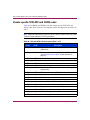
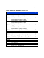
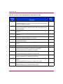
Table 1: Related Documentation
Item
Document Name
Document Part Number
1.
Compaq StorageWorks Modular Array Configuration Guide
EK-MACON-CA
2.
HP StorageWorks HSG60 and HSG80 Array Controller and
Array Controller Software Troubleshooting Guide
EK-G80TS-SA. C01
3.
HP StorageWorks HSG60 and HSG80 Array Controller and
Array Controller Software Maintenance and Service Guide
EK-G80MS-RA. C01
12
HSG60 and HSG80 Array Controller and Array Controller Software Troubleshooting Guide
About this Guide
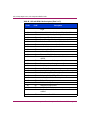
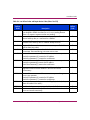
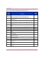
Table 1: Related Documentation (Continued)
Item
Document Name
Document Part Number
4.
HP StorageWorks Replacing a Gigabit Link Module (GLM) in
an HSG60 or HSG80 Array Controller Installation
Instructions
EK-80GLM-TE. D01
5.
HP StorageWorks Replacing DIMMs in an HSG60 or HSG80
Cache Module Installation Instructions
EK-80DIM-IM. E01
6.
HP StorageWorks Replacing an HSG60 or HSG80 Cache
Module Installation Instructions
EK-80CAH-IM. F01
7.
HP StorageWorks Replacing an HSG60 or HSG80 Array
Controller Installation Instructions
EK-80CTL-IM. F01
8.
HP StorageWorks Replacing an External Cache Battery (ECB)
Installation Instructions
EK-80ECB-IM. F01
9.
HP StorageWorks HSG80 ACS Solution Software Version
8.8 for HP-UX Installation and Configuration Guide
AA-RV1FA-TE
10.
HP StorageWorks HSG80 Enterprise/Modular Storage RAID
Array Fibre Channel Solution Software Version 8.8 for
HP-UX Release Notes
AA-RV1GA-TE
11.
HP StorageWorks HSG80 ACS Solution Software Version
8.8 for IBM AIX Installation and Configuration Guide
AA-RV1HA-TE
12.
HP StorageWorks HSG80 Enterprise/Modular Storage RAID
Array Fibre Channel Solution Software Version 8.8 for IBM
AIX Release Notes
AA-RV1JA-TE
13.
HP StorageWorks HSG80 Enterprise/Modular Storage RAID
Array Fibre Channel Solution Software Version 8.8 for Linux
X86 and Alpha Release Notes
AA-RV1KA-TE
14.
HP StorageWorks HSG80 ACS Solution Software Version
8.8 for LINUX X86 and Alpha Installation and Configuration
Guide
AA-RV1LA-TE
15.
HP StorageWorks HSG80 ACS Solution Software Version
8.8 for Novell NetWare Installation and Configuration
Guide
AA- RV1MA -TE
16.
HP StorageWorks HSG80 Enterprise/Modular Storage RAID
Array Fibre Channel Solution Software Version 8.8 for
Novell NetWare Release Notes
AA- RV1NA -TE
17.
HP StorageWorks HSG80 ACS Solution Software Version
8.8 for OpenVMS Installation and Configuration Guide
AA- RV1PA -TE
18.
HP StorageWorks HSG80 Enterprise/Modular Storage RAID
Array Fibre Channel Solution Software Version 8.8 for
OpenVMS Release Notes
AA- RV1QA -TE
HSG60 and HSG80 Array Controller and Array Controller Software Troubleshooting Guide
13
About this Guide
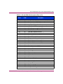
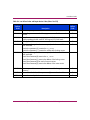
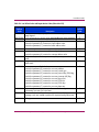
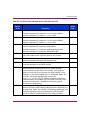
Table 1: Related Documentation (Continued)
Item
Document Name
Document Part Number
19.
HP StorageWorks HSG80 ACS Solution Software Version
8.8 for Sun Solaris Installation and Configuration Guide
AA- RV1RA -TE
20.
HP StorageWorks HSG80 Enterprise/Modular Storage RAID
Array Fibre Channel Solution Software Version 8.8 for Sun
Solaris Release Notes
AA- RV1SA -TE
21.
HP StorageWorks Command Console Version 2.4 Release
Notes
AV- RV1TA -TE
22.
HP StorageWorks Command Console Version 2.4 User
Guide
AA- RV1UA -TE
23.
HP StorageWorks Command Console Version 2.4 Online
Help (HSG60 and HSG80)
AA-RS20A-TE
AA-RS21A-TE
24.
HP StorageWorks HSG80 ACS Solution Software Version
8.8 for Tru64 UNIX Installation and Configuration Guide
AA- RV1VA -TE
25.
HP StorageWorks HSG80 Enterprise/Modular Storage RAID
Array Fibre Channel Solution Software Version 8.8 for Tru64
UNIX Release Notes
AA- RV1WA -TE
26.
Compaq StorageWorks 64-Bit PCI-to-Fibre Channel Host Bus
Adapter User Guide
AA-RKPDB-TE
27.
Digital StorageWorks UltraSCSI RAID Enclosure
(DS-BA370-Series) User’s Guide
EK-BA370-UG. B01
28.
HP StorageWorks HSG80 ACS Solution Software
Version 8.8 for Windows Installation and Configuration
Guide
AA- RV1XA -TE
29.
HP StorageWorks HSG80 ACS Solution Software
Version 8.8 for Windows Release Notes
AA-RV1YA-TE
30.
HP StorageWorks Enterprise/Modular Storage RAID Array
Fibre Channel Arbitrated Loop Configurations Application
Note
AA-RS1ZB-TE
31.
HP StorageWorks Enterprise/Modular Storage RAID Array
Fibre Channel Arbitrated Loop Configurations for Novell
Netware Application Note
AA-RVHHA-TE
32.
HP StorageWorks Addendum for ACS Solution Software Differences Between HSG60 and HSG80 Array Controllers
AV-RV2MA-TE
14
HSG60 and HSG80 Array Controller and Array Controller Software Troubleshooting Guide
About this Guide
Conventions
Conventions consist of the following:
■
Document conventions
■
Text symbols
■
Equipment symbols
Document conventions
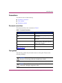
This document follows the conventions in Table 2.
Table 2: Document Conventions
Convention
Element
Blue text: Figure 1
Cross-reference links
Bold
Menu items, buttons, keys, tabs, and
box names
Italics
Text emphasis and document titles in
body text
Monospace font
User input, commands, code, file and
directory names, and system responses
(output and messages)
Monospace, italic font
Command-line and code variables
Blue underlined sans serif font text
(http://www.hp.com)
Website addresses
Text symbols
The following symbols may be found in the text of this guide. They have the
following meanings:
WARNING: Text set off in this manner indicates that failure to follow
directions in the warning could result in bodily harm or death.
Caution: Text set off in this manner indicates that failure to follow directions
could result in damage to equipment or data.
HSG60 and HSG80 Array Controller and Array Controller Software Troubleshooting Guide
15
About this Guide
Tip: Text in a tip provides additional help to readers by providing nonessential or
optional techniques, procedures, or shortcuts.
Note: Text set off in this manner presents commentary, sidelights, or interesting points
of information.
Equipment symbols
The following equipment symbols may be found on hardware for which this guide
pertains. They have the following meanings:
Any enclosed surface or area of the equipment marked with these
symbols indicates the presence of electrical shock hazards. Enclosed
area contains no operator serviceable parts.
WARNING: To reduce the risk of personal injury from electrical shock
hazards, do not open this enclosure.
Any RJ-45 receptacle marked with these symbols indicates a network
interface connection.
WARNING: To reduce the risk of electrical shock, fire, or damage to
the equipment, do not plug telephone or telecommunications
connectors into this receptacle.
Any surface or area of the equipment marked with these symbols
indicates the presence of a hot surface or hot component. Contact with
this surface could result in injury.
WARNING: To reduce the risk of personal injury from a hot
component, allow the surface to cool before touching.
16
HSG60 and HSG80 Array Controller and Array Controller Software Troubleshooting Guide
About this Guide
Power supplies or systems marked with these symbols indicate the
presence of multiple sources of power.
WARNING: To reduce the risk of personal injury from electrical
shock, remove all power cords to completely disconnect power
from the power supplies and systems.
Any product or assembly marked with these symbols indicates that the
component exceeds the recommended weight for one individual to
handle safely.
WARNING: To reduce the risk of personal injury or damage to the
equipment, observe local occupational health and safety requirements
and guidelines for manually handling material.
Rack stability
Rack stability protects personnel and equipment.
WARNING: To reduce the risk of personal injury or damage to the
equipment, be sure that:
■ The leveling jacks are extended to the floor.
■ The full weight of the rack rests on the leveling jacks.
■ In single rack installations, the stabilizing feet are attached to the rack.
■ In multiple rack installations, the racks are coupled.
■ Only one rack component is extended at any time. A rack may become
unstable if more than one rack component is extended for any reason.
HSG60 and HSG80 Array Controller and Array Controller Software Troubleshooting Guide
17
About this Guide
Getting help
If you still have a question after reading this document, contact an HP authorized
service provider or access our website: http://www.hp.com.
HP technical support
Telephone numbers for worldwide technical support are listed on the following
HP website: http://www.hp.com/support/. From this website, select the country
of origin.
Note: For continuous quality improvement, calls may be recorded or monitored.
Be sure to have the following information available before calling:
■
Technical support registration number (if applicable)
■
Product serial numbers
■
Product model names and numbers
■
Applicable error messages
■
Operating system type and revision level
■
Detailed, specific questions
HP storage website
The HP website has the latest information on this product, as well as the latest
drivers. Access storage at: http://www.hp.com/country/us/eng/prodserv/
storage.html. From this website, select the appropriate product or solution.
HP authorized reseller
For the name of your nearest HP authorized reseller:
■
■
18
In the United States, call 1-800-345-1518.
Elsewhere, visit http://www.hp.com and click Contact HP to find locations
and telephone numbers.
HSG60 and HSG80 Array Controller and Array Controller Software Troubleshooting Guide
Troubleshooting Information
1
This chapter provides guidelines for troubleshooting the controller, cache module,
and external cache battery (ECB). Topics include:
■
Typical installation problem identification checklist and troubleshooting
guidelines, page 20
■
Significant event reporting, page 31
■
Running the controller diagnostic test, page 41
■
Caching techniques, page 44
■
Device Discovery Error report, page 53
■
SHOW ELEVATION report, page 56
Note: Refer to enclosure documentation for information on troubleshooting enclosure
hardware, such as the power supplies, cooling fans, and environmental monitoring
unit (EMU).
HSG60 and HSG80 Array Controller and Array Controller Software Troubleshooting Guide
19
Troubleshooting Information
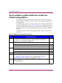
Typical installation problem identification checklist and
troubleshooting guidelines
The following checklist identifies problems that occur in a typical installation.
After identifying a problem, use Table 4 on page 22 to confirm the diagnosis and
fix the problem.
If an initial diagnosis points to several possible causes, use the tools described in
this chapter and then those in the “Utilities and Exercisers” chapter that starts on
page 67 to further refine the diagnosis. If a problem cannot be diagnosed by using
the checklist and tools, contact an HP authorized service provider for additional
support.
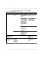
To troubleshoot the controller and supporting modules, complete the following
checklist:
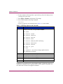
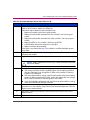
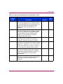
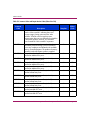
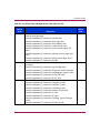
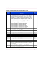
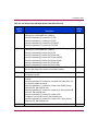
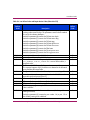
Table 3: Installation Problem Identification Checklist
Item
Troubleshooting Task
1.
At the first indication of a problem, and while you work through the CLI, enable
your capture utility to begin capturing your actions and their results. This step
saves time if you must escalate the problem later.
2.
Check the power to the enclosure and enclosure components.
3.
■
Are power cords connected properly?
■
Is power within specifications?
Done
(W)
Check the component cables.
■
Are bus cables to the controllers connected properly?
■
For BA370 enclosures, are the ECB cables connected properly?
4.
Check each program card to ensure that the card is fully seated.
5.
Check the operator control panel (OCP) and devices for LED codes.
See “Flashing OCP pattern display reporting” on page 32 and “Solid OCP
pattern display reporting” on page 34 to interpret the LED codes.
6.
Connect a local terminal to the controller and then check the controller with the
following command:
SHOW ELEVATION
20
HSG60 and HSG80 Array Controller and Array Controller Software Troubleshooting Guide
Troubleshooting Information
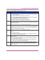
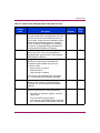
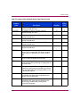
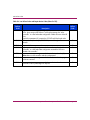
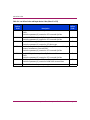
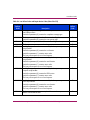
Table 3: Installation Problem Identification Checklist (Continued)
Item
7.
Troubleshooting Task
Done
(W)
Use the Fault Management Utility (FMU) for last failure or memory system failure
entries.
Show these codes and translate the Last Failure Codes they contain. For more
information, see the “Utilities and Exercisers” chapter on page 67, “Displaying
last failure entries” section that starts on page 68, and “Translating event
codes” section that starts on page 70.
If the controller failed so that it could not support a local terminal for FMU,
check the host error log for the Instance or Last Failure Codes. To interpret the
event codes, see the “Instance Codes” chapter that starts on page 177 and
the “Last Failure Codes” chapter that starts on page 211.
8.
If the controllers fail and restart repeatedly, issue the following FMU commands:
■
■
■
SHOW LAST_ALL FULL
SHOW DEVICE_INFO
SHOW DEVICE_ERROR
9.
If the problem is recurring, synchronize the controller times and host times to help
with further troubleshooting.
10.
For recurring problems with hosts other than HP Tru64 UNIX and OpenVMS, log
the console output in real time.
HSG60 and HSG80 Array Controller and Array Controller Software Troubleshooting Guide
21
Troubleshooting Information
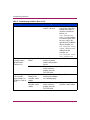
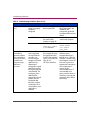
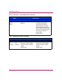
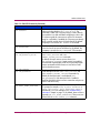
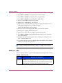
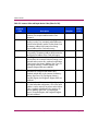
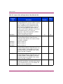
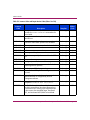
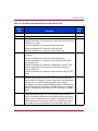
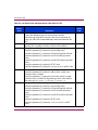
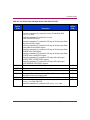
After identifying a problem, use Table 4 to resolve the problem.
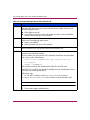
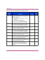
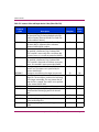
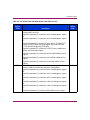
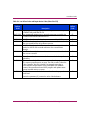
Table 4: Troubleshooting Guidelines (Sheet 1 of 9)
Symptom
Possible Cause
Investigation
Remedy
Check power to
subsystem and power
supplies on controller
enclosure.
Replace cord or (BA370
enclosure only) AC input
box.
BA370 enclosure only:
Ensure that all cooling
fans are installed. If
one or more fans are
missing or all are
inoperative for more
than 8 minutes, the
EMU shuts down the
subsystem.
Turn off power switch on
AC input box. Replace
cooling fan. Restore
power to subsystem.
BA370 enclosure only:
Determine if the
standby power switch
on the PVA was
pressed for more than
5 seconds.
Press the alarm control
switch on the EMU.
Failed controller.
If the previous
remedies fail to resolve
the problem, check
OCP LED codes.
Replace controller.
Reset button lit
steadily; other LEDs
also lit.
Various.
Note OCP LED Codes.
Follow repair action by
using Table 5 on
page 32.
Reset button
flashing; other LEDs
also lit.
Device in error or
failedset on
corresponding
device port with
other LEDs lit.
SHOW device FULL.
Follow repair action by
using Table 6 on
page 35.
Reset button not lit.
22
No power to
subsystem.
HSG60 and HSG80 Array Controller and Array Controller Software Troubleshooting Guide
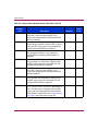
Troubleshooting Information
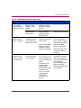
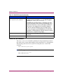
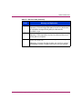
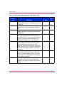
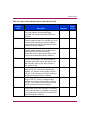
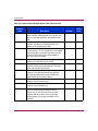
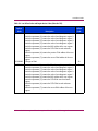
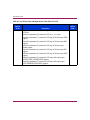
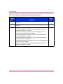
Table 4: Troubleshooting Guidelines (Sheet 2 of 9)
Symptom
Possible Cause
Investigation
Remedy
Incorrect command
syntax.
See the controller CLI
reference guide for the
SET FAILOVER
command.
Use the correct command
syntax.
Different software
versions on
controllers.
Check software
versions on both
controllers.
Update one or both
controllers so that both
use the same software
version.
Incompatible
hardware.
Check hardware
versions.
Upgrade controllers so
that they use compatible
hardware.
Controller previously
set for failover.
Ensure that neither
controller is configured
for failover.
Use the
Failed controller.
If the previous
remedies fail to resolve
the problem, check for
OCP LED codes.
Follow repair action by
using Table 5 on page 32
or Table 6 on page 35.
Cannot set fail over
to create
dual-redundant
configuration.
SET NOFAILOVER
command on both
controllers, then reset “this
controller” for failover.
HSG60 and HSG80 Array Controller and Array Controller Software Troubleshooting Guide
23
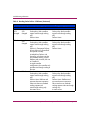
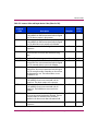
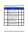
Troubleshooting Information
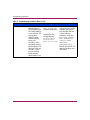
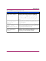
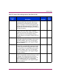
Table 4: Troubleshooting Guidelines (Sheet 3 of 9)
Symptom
Possible Cause
Investigation
Node ID is all zeros.
SHOW_THIS to see if
node ID is all zeros.
Remedy
Set node ID by using the
node ID (bar code) that is
located on the frame in
which the controller sits.
Refer to SET
THIS_CONTROLLER
NODE_ID in the controller
CLI reference guide. Also,
be sure to copy in the
right direction. If cabled to
the new controller, use
SET FAILOVER COPY=
OTHER_CONTROLLER. If
cabled to the old
controller, use
SET FAILOVER COPY=
THIS_CONTROLLER.
Nonmirrored cache:
controller reports
failed DIMM in
Cache A or B.
Mirrored cache:
"this controller"
reports DIMM 1 or
2 failed in Cache A
or B.
24
Improperly installed
DIMM.
Remove cache module
and ensure that the
DIMM is fully seated in
the slot.
Reseat DIMM.
Failed DIMM.
If the previous remedy
fails to resolve the
problem, check for
OCP LED codes.
Replace DIMM.
Improperly installed
DIMM in "this
controller" cache
module.
Remove cache module
and ensure that DIMMs
are installed properly.
Reseat DIMM.
Failed DIMM in "this
controller" cache
module.
If the previous remedy
fails to resolve the
problem, check for
OCP LED codes.
Replace DIMM in "this
controller" cache module.
HSG60 and HSG80 Array Controller and Array Controller Software Troubleshooting Guide
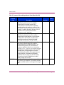
Troubleshooting Information
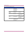
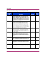
Table 4: Troubleshooting Guidelines (Sheet 4 of 9)
Symptom
Possible Cause
Investigation
Mirrored cache:
"this controller"
reports DIMM 3 or
4 failed in Cache A
or B.
Mirrored cache:
controller reports
battery not present.
Mirrored cache:
controller reports
cache or mirrored
cache has failed.
Remedy
Improperly installed
DIMM in "other
controller" cache
module.
Remove cache module
and ensure that the
DIMMs are installed
properly.
Reseat DIMM.
Failed DIMM in
"other controller"
cache module.
If the previous remedy
fails to resolve the
problem, check for
OCP LED codes.
Replace DIMM in "other
controller" cache module.
Memory module was
installed before the
cache module was
connected to an ECB.
BA370 enclosure: ECB
cable not connected to
cache module.
BA370 enclosure:
Connect ECB cable to
cache module, and then
restart both controllers by
pushing their Reset
buttons simultaneously.
Primary data and the
mirrored copy data
are not identical.
Model 2100 and 2200
enclosures: ECB not
installed or seated
properly in backplane.
SHOW
THIS_CONTROLLER
indicates that the cache
or mirrored cache has
failed.
Spontaneous FMU
message displays:
Primary cache
declared failed—data
inconsistent with
mirror, or mirrored
cache declared
failed—data
inconsistent with
primary.
Model 2100 and 2200
enclosures: Install or
reseat ECB.
Enter the SHUTDOWN
command on controllers
that report the problem.
(This command flushes the
cache contents to
synchronize the primary
and mirrored data.)
Restart the controllers that
were shut down.
HSG60 and HSG80 Array Controller and Array Controller Software Troubleshooting Guide
25
Troubleshooting Information
Table 4: Troubleshooting Guidelines (Sheet 5 of 9)
Symptom
Possible Cause
Investigation
Invalid cache.
26
Mirrored-cache
mode discrepancy.
This discrepancy can
occur after installing
a new controller. The
existing cache
module is set for
mirrored caching,
but the new
controller is set for
unmirrored caching.
This discrepancy can
also occur if the new
controller is set for
mirrored caching,
but the existing
cache module is not.
SHOW
THIS_CONTROLLER
indicates invalid cache.
Spontaneous FMU
message displays:
Cache modules
inconsistent
with mirror mode.
Remedy
Connect a terminal to the
maintenance port on the
controller reporting the
error and clear the error
with the following
command—all on one
line: CLEAR_ERRORS
THIS_CONTROLLER
INVALID_CACHE
NODESTROY_
UNFLUSHED_DATA.
Refer to the controller CLI
reference guide for more
information.
HSG60 and HSG80 Array Controller and Array Controller Software Troubleshooting Guide
Troubleshooting Information
Table 4: Troubleshooting Guidelines (Sheet 6 of 9)
Symptom
Possible Cause
Investigation
Cache module can
erroneously contain
unflushed writeback
data. This can occur
after installing a new
controller. The
existing cache
module might
indicate that the
cache module
contains unflushed
writeback data, but
the new controller
expects to find no
data in the existing
cache module.
This error can also
occur if installing a
new cache module
for a controller that
expects writeback
data in the cache.
SHOW
THIS_CONTROLLER
indicates invalid cache.
No spontaneous FMU
message.
Remedy
Connect a terminal to the
maintenance port on the
controller reporting the
error, and clear the error
with the following
command—all on one
line: CLEAR_ERRORS
THIS_CONTROLLER
INVALID_CACHE
DESTROY_UNFLUSHED_
DATA. Refer to the
controller CLI reference
guide for more
information.
Refer to the HP
StorageWorks HSG60
and HSG80 Array
Controller and Array
Controller Software
Maintenance and Service
Guide.
HSG60 and HSG80 Array Controller and Array Controller Software Troubleshooting Guide
27
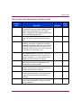
Troubleshooting Information
Table 4: Troubleshooting Guidelines (Sheet 7 of 9)
Symptom
Possible Cause
Investigation
Cannot add device.
28
Remedy
Illegal device.
See product-specific
release notes that
accompanied the
software release for the
most recent list of
supported devices.
Replace device.
Device not properly
installed in
enclosure.
Ensure that the device
is fully seated.
Firmly press the device
into the bay.
Failed device.
Check for presence of
device LEDs.
Follow repair action in the
documentation provided
with the enclosure or
device.
Failed power
supplies.
Check for presence of
power supply LEDs.
Follow repair action in the
documentation provided
with the enclosure or
power supply.
Failed bus to device.
If the previous
remedies fail to resolve
the problem, check for
OCP LED codes.
Replace enclosure.
HSG60 and HSG80 Array Controller and Array Controller Software Troubleshooting Guide
Troubleshooting Information
Table 4: Troubleshooting Guidelines (Sheet 8 of 9)
Symptom
Possible Cause
Investigation
Remedy
Incorrect command
syntax.
See the controller CLI
reference guide for the
appropriate ADD
command.
Reconfigure storageset
with correct command
syntax.
Exceeded maximum
number of
storagesets.
Use the SHOW
STORAGESETS
command to count the
number of storagesets
configured on the
controller.
Delete unused storagesets.
Failed battery on
ECB. An ECB or
uninterruptible
power supply (UPS)
is required for
RAIDsets and
mirrorsets.
Use the SHOW THIS
command to check the
ECB battery status.
Replace the ECB if
required.
Cannot assign unit
number to
storageset.
Incorrect command
syntax.
See the controller CLI
reference guide for
correct syntax.
Reassign the unit number
with the correct syntax.
Unit is available but
not online.
After created, the
unit automaticaly
comes online.
None.
None.
Host cannot see
device.
Broken cables.
Check for broken
cables.
Replace broken cables.
Cannot configure
storagesets.
HSG60 and HSG80 Array Controller and Array Controller Software Troubleshooting Guide
29
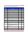
Troubleshooting Information
Table 4: Troubleshooting Guidelines (Sheet 9 of 9)
Symptom
Possible Cause
Investigation
Host cannot access
unit.
Host files or device
drivers not properly
installed or
configured.
Check for the required
device special files.
Configure device special
files as described in the
installation and
configuration guide that
accompanied the software
release.
Invalid Cache.
See the description for
the invalid cache
symptom on page 26.
See the description for the
invalid cache symptom.
Units have lost data.
Issue the
Clear these units with:
CLEAR_ERRORS
unit-number
LOST_DATA.
SHOW unit-number
FULL command.
Host log file or
maintenance
terminal indicates
that a forced error
occurred while the
controller was
reconstructing a
RAIDset or
mirrorset.
30
Remedy
Unrecoverable read
errors might have
occurred while the
controller was
reconstructing the
storageset. A flawed
data block was
detected and
reassigned to a good
data block; however,
the original data was
unrecoverable. The
reassigning of the
data block has
repaired the original
problem, but the
reassigned data
block now contains
invalid data. This is
normal after a minor
media flaw is
detected.
Conduct a read scan of
the storageset by using
the appropriate utility
from the host operating
system, such as the DD
utility for an
HP Tru64 UNIX host.
Rebuild the storageset,
and then restore
storageset data from a
backup source. While the
controller is reconstructing
the storageset, monitor the
host error log activity or
spontaneous event reports
on the maintenance
terminal for any
unrecoverable errors. If
unrecoverable errors
persist, note the device on
which they occurred, and
replace the device before
proceeding.
HSG60 and HSG80 Array Controller and Array Controller Software Troubleshooting Guide
Troubleshooting Information
Significant event reporting
The controller fault management software reports information about significant
events that occur. These events are reported by:
■
Maintenance terminal displays.
■
Host error logs.
■
OCP LEDs.
Some events cause controller operation to halt; others allow the controller to
remain operable. Both types of events are detailed in the following sections.
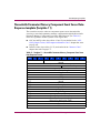
Reporting events that cause controller operation to halt
Events that cause the controller to halt operations are reported in three possible
ways:
■
A flashing OCP pattern display
■
A solid OCP pattern display
■
Last Failure reporting
Use Table 5 on page 32 to interpret flashing OCP patterns and Table 6 on page 35
to interpret solid (on) OCP patterns. In the Error column of the solid OCP
patterns, there are two separate descriptions. The first denotes the actual error
message that appears on the terminal, and the second provides a more detailed
explanation of the designated error.
Use the following legend to interpret both tables as indicated:
■
n
= Reset button flashing (in Table 5) or on (in Table 6)
■
o
= Reset button off
■
l
= LED flashing (in Table 5) or on (in Table 6)
■
m = LED off
Note: If the Reset button is flashing and an LED is on, either the devices on the bus
that corresponds to the LED do not match the controller configuration, or an error
occurred in one of the devices on that bus. Also, a single LED that is turned on
indicates a failure of the drive on that bus.
HSG60 and HSG80 Array Controller and Array Controller Software Troubleshooting Guide
31
Troubleshooting Information
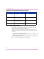
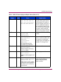
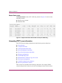
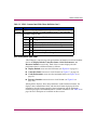
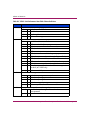
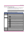
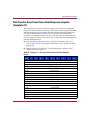
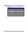
Flashing OCP pattern display reporting
Certain events can cause a flashing display of the OCP LEDs. Each event and the
resulting pattern are described in Table 5.
Note: Remember that a solid black pattern represents a flashing display. A white
pattern indicates off. All LEDs flash at the same time and at the same rate.
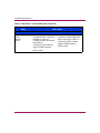
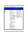
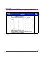
Table 5: Flashing OCP Pattern Displays and Repair Actions
OCP
Code
Error
nmmmmml
1
Program card EDC error.
Replace program card.
nmmmlmm
4
Timer zero on the
processor is bad.
Replace controller.
nmmmlml
5
Timer one on the
processor is bad.
Replace controller.
nmmmllm
6
Processor Guarded
Memory Unit (GMU) is
bad.
Replace controller.
nmmlmll
B
Nonvolatile Journal
Memory (JSRAM)
structure is bad
because of a memory
error or an incorrect
upgrade procedure.
Verify the correct upgrade (refer
to the controller release notes
and other related
documentation, if available). If
error continues, replace
controller.
nmmllml
D
One or more bits in the
diagnostic registers
did not match the
expected reset value.
Press the Reset button to restart
the controller. If this does not
correct the error, replace the
controller.
nmmlllm
E
Memory error in the
JSRAM.
Replace controller.
nmmllll
F
Wrong image found on
program card.
Replace program card or
replace controller if needed.
Controller module
memory is bad.
Replace controller.
Pattern
nmlmmmm
32
10
Repair Action
HSG60 and HSG80 Array Controller and Array Controller Software Troubleshooting Guide
Troubleshooting Information
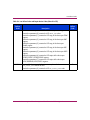
Table 5: Flashing OCP Pattern Displays and Repair Actions (Continued)
Pattern
OCP
Code
Error
Repair Action
nmlmmlm
12
Controller module
memory addressing is
malfunctioning.
Replace controller.
nmlmmll
13
Controller module
memory parity is not
working.
Replace controller.
nmlmlmm
14
Controller module
memory controller timer
has failed.
Replace controller.
nmllmml
15
Controller module
memory controller
interrupt handler has
failed.
Replace controller.
nmllllm
1E
During the diagnostic
memory test, the
controller module
memory controller
caused an unexpected
Non-Maskable Interrupt
(NMI).
Replace controller.
nlmmlmm
24
Card code image changed
when the contents were
copied to memory.
Replace controller.
nllmmmm
30
JSRAM battery is bad.
Replace controller.
nllmmlm
32
First-half diagnostics
of the Time of Year
Clock failed.
Replace controller.
nllmmll
33
Second-half diagnostics
of the Time of Year
Clock failed.
Replace controller.
nllmlml
35
Processor bus-to-device
bus bridge chip is bad.
Replace controller.
nlllmll
3B
An unnecessary
interrupt is pending.
Replace controller.
HSG60 and HSG80 Array Controller and Array Controller Software Troubleshooting Guide
33
Troubleshooting Information
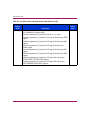
Table 5: Flashing OCP Pattern Displays and Repair Actions (Continued)
Pattern
OCP
Code
Error
Repair Action
nllllmm
3C
An unexpected fault
occurred during
initialization.
Replace controller.
nllllml
3D
An unexpected maskable
interrupt occurred
during initialization.
Replace controller.
nlllllm
3E
An unexpected NMI
occurred during
initialization.
Replace controller.
nllllll
3F
An invalid process ran
during initialization.
Replace controller.
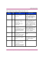
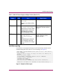
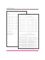
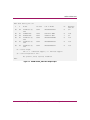
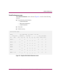
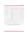
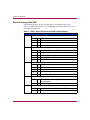
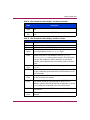
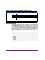
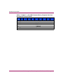
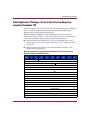
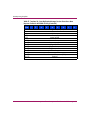
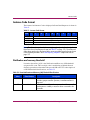
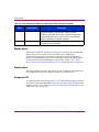
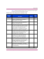
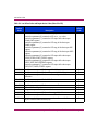
Solid OCP pattern display reporting
Certain events cause the OCP LEDs to display on or solid. Each event and the
resulting pattern are described in Table 6 on page 35.
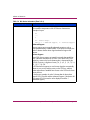
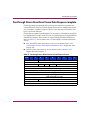
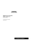
Information related to the solid OCP patterns is automatically displayed on the
maintenance terminal (unless disabled with the FMU) and use %FLL formatting
(see Figure 1).
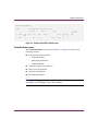
%FLL--HSG> --13-MAY-2004 04:39:45 (time not set)-- OCP Code: 38
Controller operation terminated.
%FLL--HSG> --13-MAY-2004 04:32:26 (time not set)-- OCP Code: 26
Memory module is missing.
Figure 1: OCP pattern display showing %FLL formatting
34
HSG60 and HSG80 Array Controller and Array Controller Software Troubleshooting Guide
Troubleshooting Information
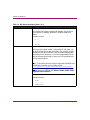
Table 6: Solid OCP Pattern Displays and Repair Actions (Sheet 1 of 5)
Pattern
OCP
Code
Error
Repair Action
ommmmmm
0
Catastrophic controller
or power failure
occurred.
Check power. If good, reset
controller. If problem persists,
reseat controller module and
reset controller. If problem is still
evident, replace controller
module.
nmmmmmm
0
No program card
detected or kill
asserted by OTHER
CONTROLLER.
Ensure that the program card is
properly seated while resetting
the controller. If the error
persists, try the card with another
controller; or replace the card.
Otherwise, replace the controller
that reported the error.
Controller unable to read
program card.
nlmmlml
nlmmllm
25
26
The same bugcheck has occurred
three times within 10 minutes,
and controller operation has
halted.
Reset the controller. If this fault
pattern is displayed repeatedly,
follow the repair actions
associated with the Last Failure
Code that is repeatedly
terminating controller execution.
Indicated memory module
is missing.
Insert memory module (cache
board).
Recursive bugcheck
detected.
Controller is unable to detect a
particular memory module.
nlmmlll
nlmlmmm
27
28
Memory module has
insufficient usable
memory.
Replace indicated DIMMs.
An unexpected Machine
Fault NMI occurred
during Last Failure
processing.
Reset the controller.
This indication is only provided
after Fault LED logging is
enabled.
A machine fault was detected
while a NMI was processing.
HSG60 and HSG80 Array Controller and Array Controller Software Troubleshooting Guide
35
Troubleshooting Information
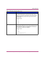
Table 6: Solid OCP Pattern Displays and Repair Actions (Sheet 2 of 5)
Pattern
nlmlmml
OCP
Code
29
Error
EMU protocol version
incompatible.
The microcode in the EMU and
the software in the controller are
not compatible.
nlmlmlm
2A
All enclosure I/O
modules are not of the
same type.
Enclosure I/O modules are a
combination of single-ended and
differential.
nlmlmll
2B
Jumpers, not
terminators, found on
backplane.
One or more SCSI bus
terminators are either missing
from the backplane or broken.
nlmllmm
2C
Enclosure I/O
termination power out
of range.
Faulty or missing I/O module
causes enclosure I/O termination
power to be out of range.
nlmllml
2D
Master enclosure SCSI
buses are not all set
to ID 0.
Repair Action
Upgrade either the EMU
microcode or the software (refer
to the release notes that
accompanied the controller
software).
Ensure that the I/O modules in
an extended subsystem are
either all single-ended or all
differential, but not both.
Ensure that enclosure SCSI bus
terminators are installed and that
no jumpers are installed. Replace
the failed terminator if the
problem continues.
Ensure that all of the enclosure
device SCSI buses have an I/O
module. If problem persists,
replace the failed I/O module.
Set the PVA ID to 0 for the
enclosure with the controllers. If
the problem persists, try the
following repair actions:
1. Replace the PVA module.
2. Replace the EMU.
3. Remove all devices.
4. Replace the enclosure.
36
HSG60 and HSG80 Array Controller and Array Controller Software Troubleshooting Guide
Troubleshooting Information
Table 6: Solid OCP Pattern Displays and Repair Actions (Sheet 3 of 5)
Pattern
nlmlllm
OCP
Code
2E
Error
Multiple enclosures
have the same SCSI ID.
More than one enclosure
has the same SCSI ID.
Repair Action
Reconfigure the PVA ID to
uniquely identify each enclosure
in the subsystem. The enclosure
with the controllers must be set to
PVA ID 0; additional enclosures
must use PVA IDs 2 and 3. If the
error continues after PVA settings
are unique, replace each PVA
module one at a time. Check the
enclosure if the problem remains.
nlmllll
2F
Memory module has
illegal DIMM
configuration.
Verify that DIMMs are installed
correctly.
nllmmmm
30
An unexpected bugcheck
occurred before
subsystem
initialization
completed.
Reinsert controller. If the problem
persists, reset the controller. If the
error persists, try resetting the
controller again, and replace the
controller if no change occurs.
An unexpected Last Failure
occurred during initialization.
nllmmml
31
ILF$INIT unable to
allocate memory.
Replace controller.
Attempt to allocate memory by
ILF$INIT failed.
nllmmlm
32
Code load program card
write failure.
Replace program card.
Attempt to update program card
failed.
nllmmll
33
Nonvolatile program
memory (NVPM) structure
revision too low.
NVPM structure revision number
is lower than can be handled by
the software version attempting
to be executed.
Verify that the program card
contains the latest software
version. If the error persists,
replace controller.
HSG60 and HSG80 Array Controller and Array Controller Software Troubleshooting Guide
37
Troubleshooting Information
Table 6: Solid OCP Pattern Displays and Repair Actions (Sheet 4 of 5)
Pattern
nllmlml
OCP
Code
35
Error
An unexpected bugcheck
occurred during Last
Failure processing.
Repair Action
Reset controller.
Last failure processing
interrupted by another last
failure event.
nllmllm
36
Hardware-induced
controller reset
expected and failed.
Replace controller.
nllmlll
37
Software-induced
controller reset
expected and failed.
Replace controller.
nlllmmm
38
Controller operation
halted.
Reset controller.
Last Failure event required
termination of controller
operation, for example:
SHUTDOWN through the CLI.
nlllmml
39
NVPM configuration
inconsistent.
Replace controller.
Device configuration within the
NVPM is inconsistent.
nlllmlm
3A
An unexpected NMI
occurred during Last
Failure processing.
Replace controller.
Last Failure processing
interrupted by an NMI.
nlllmll
3B
NVPM read loop hang
occurred.
Replace controller.
Attempt to read data from
NVPM failed.
38
HSG60 and HSG80 Array Controller and Array Controller Software Troubleshooting Guide
Troubleshooting Information
Table 6: Solid OCP Pattern Displays and Repair Actions (Sheet 5 of 5)
Pattern
nllllmm
OCP
Code
3C
Error
NVPM write loop hang
occurred.
Repair Action
Replace controller.
Attempt to write data to NVPM
failed.
nllllml
3D
NVPM structure revision
is higher than image.
NVPM structure revision number
is higher than the one that can
be handled by the software
version attempting to execute.
nllllll
3F
DAEMON diagnostic
failed hard in
non-fault tolerant
mode.
Replace program card with one
that contains the latest software
version.
Verify that cache module is
present. If the error persists,
replace controller.
DAEMON diagnostic detected
critical hardware component
failure; controller can no longer
operate.
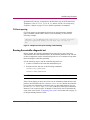
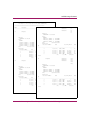
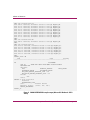
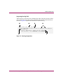
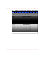
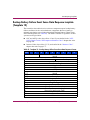
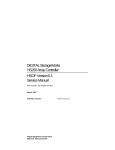
Last failure reporting
Last Failures are automatically displayed on the maintenance terminal (unless
disabled through the FMU) and use %LFL formatting (see Figure 2).
%LFL--HSG> --13-MAY-2004 04:39:45 (time not set)-- Last Failure
Code: 20090010
Power On Time: 0. Years, 14. Days, 19. Hours, 58. Minutes, 42.
Seconds
Controller Model: HSG80
Serial Number: AA12345678 Hardware Version: 0000(00)
Software Version: V088P(FF)
Informational Report
Instance Code: 0102030A
Last Failure Code: 20090010 (No Last Failure Parameters)
Additional information is available in Last Failure Entry: 1.
Figure 2: Sample Last Failure report
HSG60 and HSG80 Array Controller and Array Controller Software Troubleshooting Guide
39
Troubleshooting Information
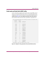
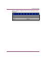
Last Failures are also reported to the host error log on Template 01, following a
restart of the controller. For a detailed explanation of this template, see the “ASC,
ASCQ, Repair Action, and Component Identifier Codes” chapter that starts on
page 161.
Reporting events that allow controller operation to continue
Events that do not cause controller operation to halt are displayed in one of two
ways:
■
Spontaneous Event log
■
CLI Event reporting
Spontaneous Event log
Spontaneous Event logs are automatically displayed on the maintenance terminal
(unless disabled with the FMU) and use %EVL formatting, as illustrated in
Figure 3.
%EVL--HSG> --13-OCT-2004 04:32:47 (time not set)-- Instance Code: 0102030A (not yet
reported to host)
Template: 1.(01)
Power On Time: 0. Years, 14. Days, 19. Hours, 58. Minutes, 43. Seconds
Controller Model: HSG80
Serial Number: AA12345678 Hardware Version: 0000(00)
Software Version: V088P(FF)
Informational Report
Instance Code: 0102030A
Last Failure Code: 011C0011
Last failure parameter[0.] 0000003F
%EVL--HSG> --13-OCT-2004 04:32:47 (time not set)-- Instance Code: 82042002 (not yet
reported to host)
Template: 13.(13)
Power On Time: 0. Years, 14. Days, 19. Hours, 58. Minutes, 43. Seconds
Controller Model: HSG80
Serial Number: AA12345678 Hardware Version: 0000(00)
Software Version: V088P(FF)
Header type: 00 Header flags: 00
Test entity number: 0F Test number Demand/Failure: F8 Command: 01
Error Code: 0008 Return Code: 0005 Address of Error: A0000000
Expected Error Data: 44FCFCFC Actual Error Data: FFFF01BB
Extra Status(1): 00000000 Extra Status(2): 00000000 Extra Status(3): 00000000
Instance Code: 82042002
HSG>
Figure 3: Sample Spontaneous Event logs showing %EVL formatting
40
HSG60 and HSG80 Array Controller and Array Controller Software Troubleshooting Guide
Troubleshooting Information
Spontaneous Event logs are reported to the Host Error log on SCSI Sense Data
Templates 01, 04, 05, 11, 12, 13, 14, 41, 51, and 90. See the “Event Reporting
Templates” chapter on page 135 for a detailed explanation of templates.
CLI Event reporting
CLI Event reports are automatically displayed on the maintenance terminal
(unless disabled with the FMU) and use %CER formatting, as shown in the
following example:
%CER--HSG> --13-OCT-2004 04:32:20 (time not set)-- Previous controlleroperation stopped with display of solid fault code, OCP Code: 3F
HSG>
Figure 4: Sample CLI Event report showing %CER formatting
Running the controller diagnostic test
During startup, the controller automatically tests the device ports, host ports,
cache module, and value-added functions. If intermittent problems occur with one
of these components, run the controller diagnostic test in a continuous loop rather
than restarting the controller repeatedly.
Use the following steps to run the controller diagnostic test:
1. Connect a terminal to the controller maintenance port.
2. Start the self-test with one of the following commands:
SELFTEST THIS_CONTROLLER
SELFTEST OTHER_CONTROLLER
Note: The self-test runs until it detects an error or until you press the Reset button.
If the self-test detects an error, the self-test saves information about the error and
produces an OCP LED code for a daemon hard error. Restart the controller
to write the error information to the host error log, then check the host error log
for a built-in self-test failure event report. This report contains an
Instance Code, located at offset 32 through 35, that can be used to determine the
cause of the error. See the “Translating event codes” section that starts on page 70
for help translating Instance Codes.
HSG60 and HSG80 Array Controller and Array Controller Software Troubleshooting Guide
41
Troubleshooting Information
ECB charging diagnostics
After restarting the controller, the diagnostic routines automatically check the
charge of each ECB battery. If the battery is fully charged, the controller reports
the battery as good and rechecks the battery every 24 hours. If the battery is
charging, the controller rechecks the battery every 4 minutes. A battery is reported
as being either above or below 50 percent capacity. A battery below 50 percent
capacity is referred to as low.
The 4-minute polling continues for the maximum allowable time to recharge the
battery—up to 10 hours for a BA370 enclosure, or 3 1/2 hours for a Model 2100
or 2200 enclosure. If the battery does not charge sufficiently after the allotted
time, the controller declares the battery as failed.
Battery hysteresis
If you are charging an ECB battery, writeback caching is allowed as long as a
previous downtime did not drain more than 50 percent battery capacity. If an ECB
battery is operating below 50 percent capacity, the battery is considered to be low
and writeback caching is disabled.
ECB battery capacity depends on the size of the cache module memory
configuration as shown in Table 7. For example, after the batteries are fully
charged, an ECB can preserve 512 MB of cache memory for 24 hours.
Table 7: ECB Capacity Based on Memory Size
Size
DIMM Combinations
Capacity in Hours (Days)
128 MB
Four, 32 MB each
96 (4)
128 MB
One, 128 MB each
96 (4)
256 MB
Two, 128 MB each
48 (2)
512 MB
Four, 128 MB each
24 (1)
Caution: HP recommends replacing the ECB every 3 1/2 years to prevent
battery failure. If you are shutting down your controller for longer than one
day, complete the additional steps in "Shutting Down the Subsystem" in the HP
StorageWorks HSG60 and HSG80 Array Controller and Array Controller
Software Maintenance and Service Guide. This prevents the ECB from
discharging during planned power outages.
42
HSG60 and HSG80 Array Controller and Array Controller Software Troubleshooting Guide
Troubleshooting Information
UPS used for backup power
If a UPS is used for backup power and the controllers are set to
DATACENTER_WIDE, the controllers check the battery and indicate if a battery
failure exists, but they do not take any action (see Figure 5 for an example of the
screen display after issuing the SHOW THIS CLI command):
HSG> SHOW THIS
Controller:
HSG80 ZG93413884 Software V88.x-0, Hardware
NODE_ID
E06
= 5000-1FE1-0002-A270
ALLOCATION_CLASS = 0
SCSI_VERSION
= SCSI-2
Configured for MULTIBUS_FAILOVER with ZG93513566
In dual-redundant configuration
Device Port SCSI address 6
Time: 29-JUN-2004 13:45:57
Command Console LUN is lun 0 (IDENTIFIER = 300)
Host Connection Table is LOCKED
Smart Error Eject Disabled
.
.
.
Battery:
UPS = DATACENTER_WIDE
FULLY CHARGED
Expires:
18-JUN-2007
Previous controller operation terminated by power failure.
Figure 5: SHOW THIS CLI sample screen display
Refer to the appropriate installation and configuration guide and controller CLI
reference guide for information about the UPS switches.
HSG60 and HSG80 Array Controller and Array Controller Software Troubleshooting Guide
43
Troubleshooting Information
Caching techniques
The cache module supports the following caching techniques to increase
subsystem read and write performance:
■
Read caching
■
Read-ahead caching
■
Write-through caching
■
Writeback caching
Read caching
If the controller receives a read request from the host, the controller reads the data
from the disk drives, delivers the data to the host, and stores the data in the
supporting cache module. Subsequent reads for the same data take this data from
the supporting cache module rather than access the data from the disk drives. This
process is called read caching.
Read caching can decrease the subsystem response time to many host read
requests. If the host requests some or all of the cached data, the controller satisfies
the request from the supporting cache module rather than from the disk drives.
Read caching is enabled by default for all storage units.
For more details, refer to the following CLI commands in the controller CLI
reference guide:
■
SET unit-number MAXIMUM_CACHED_TRANSFER=nn
■
SET unit-number MAX_READ_CACHED_TRANSFER_SIZE=nn
■
SET unit-number READ_CACHE
Read-ahead caching
Read-ahead caching begins after the controller has already processed a read
request and the controller receives a subsequent read request from the host. If the
controller does not find the data in the cache memory, the controller reads the data
from the disk drives and sends this data to the cache memory.
During read-ahead caching, the controller anticipates subsequent read requests
and begins to prefetch the next blocks of data from the disk drives as the controller
sends the requested read data to the host. These are parallel actions. The controller
notifies the host of the read completion, and subsequent sequential read requests
are satisfied from the cache memory. Read-ahead caching is enabled by default
for all disk units.
44
HSG60 and HSG80 Array Controller and Array Controller Software Troubleshooting Guide
Troubleshooting Information
Write-through caching
After the controller receives a write request from the host, the controller places the
data in the supporting cache module, writes the data to the disk drives, and then
notifies the host that the write operation is complete. This process is called
write-through caching because the data actually passes through—and is stored
in—the cache memory along the way to the disk drives.
If read caching is enabled for a storage unit, write-through caching is
automatically enabled.
Writeback caching
Writeback caching improves the subsystem response time to write requests by
allowing the controller to declare the write operation complete as soon as the data
reaches the supporting cache memory. The controller performs the slower
operation of writing the data to the disk drives at a later time. For more details,
refer to the following CLI commands in the controller CLI reference guide:
■
SET unit-number MAXIMUM_CACHED_TRANSFER=nn
■
SET unit-number MAX_WRITE_CACHED_TRANSFER_SIZE=nn
■
SET unit-number WRITEBACK_CACHE
Writeback caching is enabled by default for all units. The controller only provides
writeback caching to a unit if the cache memory is nonvolatile, as described in the
next section.
By default, the controller expects to use an ECB as the backup power source for
the cache module. However, if the subsystem is protected by a UPS, use one of
the following CLI commands to instruct the controller to use the UPS:
SET controller UPS=NODE_ONLY
or
SET controller UPS=DATACENTER_WIDE
Fault-tolerance for writeback caching
The cache module supports nonvolatile memory and dynamic cache policies to
protect the availability of cache module unwritten (writeback) data.
HSG60 and HSG80 Array Controller and Array Controller Software Troubleshooting Guide
45
Troubleshooting Information
Nonvolatile memory
The controller provides writeback caching for storage units as long as the
controller cache memory is connected to a nonvolatile backup power source, such
as an ECB. The cache module must be nonvolatile to preserve unwritten cache
data during a power failure. If the cache memory is not connected to a backup
power supply, this unwritten data is lost during a power failure.
46
HSG60 and HSG80 Array Controller and Array Controller Software Troubleshooting Guide
Troubleshooting Information
Note: Disaster-tolerant mirrorsets are not subject to this requirement.
By default, the controller expects to use an ECB as the backup power source for the
supporting cache module. However, if the subsystem is backed up by using a UPS, two
options are available that tell the controller to use the UPS:
■
For BA370 enclosures only, use the ECB and the UPS together with the following
CLI command:
SET controller UPS=NODE_ONLY
■
Use only the UPS as the backup power source with the following CLI command:
SET controller UPS=DATACENTER_WIDE
See the controller CLI reference guide for detailed descriptions of these commands.
Cache policies resulting from cache module failures
If the controller detects a full or partial failure of the supporting cache module or
ECB, the controller automatically reacts to preserve the unwritten data in the
supporting cache module. Depending upon the severity of the failure, the
controller chooses an interim caching technique—also called the cache
policy—until the cache module or ECB is repaired or replaced.
Table 8 shows the cache policies resulting from a full or partial failure of cache
module A (Cache A) in a dual-redundant controller configuration. The
consequences shown in Table 8 are the same for Cache B failures.
Table 9 on page 50 shows the cache policies resulting from a full or partial failure
of the ECB connected to Cache A in a dual-redundant controller configuration.
The consequences shown in Table 9 are the opposite for an ECB failure connected
to Cache B.
■
If the ECB is at least 50% charged, the ECB is still good and is charging.
■
If the ECB is less than 50% charged, the ECB is low but still charging.
Table 8: Cache Policies—Cache Module Status
Cache Module
Status
Cache A
Cache B
Good.
Good.
Cache Policy
Unmirrored Cache
Mirrored Cache
Data loss: None.
Data loss: None.
Cache policy: Both controllers
support writeback caching.
Cache policy: Both controllers
support writeback caching.
Failover: None.
Failover: None.
HSG60 and HSG80 Array Controller and Array Controller Software Troubleshooting Guide
47
Troubleshooting Information
Table 8: Cache Policies—Cache Module Status (Continued)
Cache Module
Status
Cache Policy
Cache A
Cache B
Multibit
cache
memory
failure.
Good.
Unmirrored Cache
Mirrored Cache
Data loss: Forced error and loss
of writeback data for which the
multibit error occurred.
Controller A detects and reports
the lost blocks.
Data loss: None. Controller A
recovers lost writeback data from
the mirrored copy on Cache B.
Cache policy: Both controllers
support writeback caching.
Failover: None.
Cache policy: Both controllers
support writeback caching.
Failover: None.
48
HSG60 and HSG80 Array Controller and Array Controller Software Troubleshooting Guide
Troubleshooting Information
Table 8: Cache Policies—Cache Module Status (Continued)
Cache Module
Status
Cache A
Cache B
DIMM or
cache
memory
controller
chip
failure.
Good.
Cache Policy
Unmirrored Cache
Data loss: Writeback data that
was not written to media when
failure occurred was not
recovered.
Cache policy: Controller A
supports write-through caching
only; Controller B supports
writeback caching.
■
Failover: In Transparent
Failover, all units fail over to
Controller B. In Multiple-bus
Failover with host-assist, only
those units that use writeback
caching, such as RAIDsets
and mirrorsets, fail over to
Controller B. All units with
lost data become inoperative
until they are cleared by
using the
Mirrored Cache
Data loss: Controller A recovers all
of writeback data from the
mirrored copy on Cache B.
Cache policy: Controller A
supports write-through caching
only; Controller B supports
writeback caching.
Failover: In Transparent Failover,
all units fail over to Controller B
and operate normally. In
Multiple-bus Failover with
host-assist, only those units that
use writeback caching, such as
RAIDsets and mirrorsets, fail over
to Controller B.
CLEAR_ERRORS
unit-number
LOST_DATA command.
Units that did not lose data
operate normally on
Controller B.
In single-controller
configurations, RAIDsets,
mirrorsets, and all units with lost
data become inoperative.
Although lost data errors can be
cleared on some units, RAIDsets
and mirrorsets remain
inoperative until the memory on
Cache A is repaired or replaced.
HSG60 and HSG80 Array Controller and Array Controller Software Troubleshooting Guide
49
Troubleshooting Information
Table 8: Cache Policies—Cache Module Status (Continued)
Cache Module
Status
Cache Policy
Cache A
Cache B
Cache
board
failure.
Good.
Unmirrored Cache
Mirrored Cache
Same as for DIMM failure (see
page 49).
Data loss: Controller A recovers all
of writeback data from the
mirrored copy on Cache B.
Cache policy: Both controllers
support write-through caching
only. Controller B cannot execute
mirrored writes because Cache A
cannot mirror Controller B
unwritten data.
Failover: None
Table 9: Resulting Cache Policies—ECB Status
ECB Status
Cache Policy
Cache A
Cache B
At least
50%
charged.
At least
50%
charged.
50
Unmirrored Cache
Mirrored Cache
Data loss: None.
Data loss: None.
Cache policy: Both controllers
continue to support writeback
caching.
Cache policy: Both controllers
continue to support writeback
caching.
Failover: None.
Failover: None.
HSG60 and HSG80 Array Controller and Array Controller Software Troubleshooting Guide
Troubleshooting Information
Table 9: Resulting Cache Policies—ECB Status (Continued)
ECB Status
Cache A
Cache B
Less than
50%
charged.
At least
50%
charged.
Cache Policy
Unmirrored Cache
Mirrored Cache
Data loss: None.
Data loss: None.
Cache policy: Controller A
supports write-through caching
only; Controller B supports
writeback caching.
Cache policy: Both controllers
continue to support writeback
caching.
Failover: In Transparent Failover,
all units fail over to Controller B.
Failover: None.
In Multiple-bus Failover with
host-assist, only those units that
use writeback caching, such as
RAIDsets and mirrorsets, fail over
to Controller B.
In single-controller
configurations, the controller only
provides write-through caching to
the units.
Failed.
At least
50%
charged.
Data loss: None.
Data loss: None.
Cache policy: Controller A
supports write-through caching
only; Controller B supports
writeback caching.
Cache policy: Both controllers
continue to support writeback
caching.
Failover: In Transparent Failover,
all units fail over to Controller B
and operate normally.
Failover: None.
In Multiple-bus Failover with
host-assist, only those units that
use writeback caching, such as
RAIDsets and mirrorsets, fail over
to Controller B.
In single-controller
configurations, the controller only
provides write-through caching to
the units.
HSG60 and HSG80 Array Controller and Array Controller Software Troubleshooting Guide
51
Troubleshooting Information
Table 9: Resulting Cache Policies—ECB Status (Continued)
ECB Status
Cache Policy
Cache A
Cache B
Less than
50%
charged.
Less than
50%
charged.
Failed.
Less than
50%
charged.
Unmirrored Cache
Mirrored Cache
Data loss: None.
Data loss: None.
Cache policy: Both controllers
support write-through caching
only.
Cache policy: Both controllers
support write-through caching
only.
Failover: None.
Failover: None.
Data loss: None.
Data loss: None.
Cache policy: Both controllers
support write-through caching
only.
Cache policy: Both controllers
support write-through caching
only.
Failover: In Transparent Failover,
all units fail over to Controller B
and operate normally.
Failover: None.
In Multiple-bus Failover with
host-assist, only those units that
use writeback caching, such as
RAIDsets and mirrorsets, fail over
to Controller B.
In single-controller
configurations, the controller only
provides write-through caching to
the units.
Failed.
52
Failed.
Data loss: None.
Data loss: None.
Cache policy: Both controllers
support write-through caching
only.
Cache policy: Both controllers
support write-through caching
only.
Failover: None. RAIDsets and
mirrorsets become inoperative.
Other units that use writeback
caching operate with
write-through caching only.
Failover: None. RAIDsets and
mirrorsets become inoperative.
Other units that use writeback
caching operate with write-through
caching only.
No restart occurs.
A restart occurs.
HSG60 and HSG80 Array Controller and Array Controller Software Troubleshooting Guide
Troubleshooting Information
Dual external cache battery failures
The array controller cache policy provides for proper handling of a single ECB
failure as described in this guide. For dual ECB failures, it states that no failover
occurs. If a dual ECB failure is detected, both controllers are restarted.
Enabling mirrored writeback cache
Before configuring dual-redundant controllers and enabling mirroring, ensure that
the following conditions are met:
■
Each cache module is configured with the same size cache, 128 MB, 256 MB,
or 512 MB.
■
Diagnostics indicate that cache is good on both cache modules.
■
Both cache modules either:
— Have an ECB connected, and the UPS switch is set by one of the
following CLI commands:
SET controller NOUPS
(no UPS is connected)
BA370 enclosure only: SET controller UPS=NODE_ONLY (a UPS is
connected)
— Do not have an ECB connected, and the UPS switch is set by the
following CLI command:
SET controller UPS=DATACENTER_WIDE
■
No unit errors are outstanding (for example, lost data or data that cannot be
written to devices).
■
Both controllers are started and configured in Failover mode.
For important considerations while configuring a subsystem for mirrored caching,
refer to the appropriate installation and configuration guide. To add or replace
DIMMs in a mirrored cache configuration, refer to the controller maintenance and
service guide.
Device Discovery Error report
The Device Discovery Error report contains information that the controller reports
to the maintenance console if it encounters errors in the Device Discovery Code
(see Figure 6 on page 54).
HSG60 and HSG80 Array Controller and Array Controller Software Troubleshooting Guide
53
Troubleshooting Information
%EVL--hsg80_bot> --08-JUN-2004 11:37:26-- Instance Code: 03D04002
Template: 65.(41)
Occurred on 08-JUN-2004 at 11:37:11
Power On Time: 2. Years, 79. Days, 13. Hours, 34. Minutes, 26. Seconds
Controller Model: HSG80
Serial Number: ZG95114377 Hardware Version:
E11(29)
Software Version: V88F-0(FF)
Port: 1. Target: 3.
ASC: (3F) ASCQ: (85)
OP|KEY: x0004
1
1
2
3
2 3
ST: x17
EC: 9.
5
4
Test unit ready or read capacity command 4
failed (refer to Table 48 on page 162).
SCSI OpCode, where 00 represents the
5
OpCode.
Sense key, where 04 represents the sense
key.
Device work descriptor (DWD) status (see
Table 10 on page 54).
DWD Error Codes (see Table 11 on
page 56).
Figure 6: Sample Device Discovery Error Report
Table 10 explains the DWD Status Codes.
Table 10: DWD Status Codes
Code
54
Description
0x00
Worked.
0x01
Compare operation failed.
0x02
VA must re-do entire XOR.
0x03
VA must re-do XOR for transfer for one or more buffers.
0x04
Drive is not responding properly.
0x05
DWD was aborted.
0x06
Tape has a serious exception.
0x07
Tape position was lost.
0x08
Cache data lost.
HSG60 and HSG80 Array Controller and Array Controller Software Troubleshooting Guide
Troubleshooting Information
Table 10: DWD Status Codes (Continued)
Code
Description
0x09
Short record.
0x0a
Long record.
0x0b
Tape flow interlocked condition.
0x0c
Some of the data is missing.
0x0d
Data is good, command retried.
0x0e
Data is good, device retried.
0x0f
Device reported media error.
0x10
From device sense data.
0x11
Device reported media error.
0x12
Device reported write protect.
0x13
Disk reported ILI, FM or EOM.
0x14
Device reported.
0x15
See sense data for error.
0x16
LUN responded that it was not ready.
0x17
No response from targets.
0x18
Retry requested by ER thread.
0x19
Init only—DWD which initiated reset.
0x20
Deferred error for tape DWD.
0x21
Data is good, recommend revector.
0x22
Data is good, recommend re-write.
0x23
Request sense failed for command.
0x24
Request sense failed for command.
0x25
Media may have changed.
0x26
A drive reported forced error.
The following codes are disk-specific and are never seen by VA.
0x27
An unexpected SCSI status byte was returned in response to a CDI
SCSI command.
0x28
A CDI MSJ OUT byte was unexpectedly rejected by the device.
0x29
A severe error occurred for a CDI SCSI command.
HSG60 and HSG80 Array Controller and Array Controller Software Troubleshooting Guide
55
Troubleshooting Information
Table 11 explains the Error Codes (EC).
Table 11: EC Codes
Code
Description
0
Spin failed on drive.
1
Pub device type does not match NVMEM.
2
Unknown device type.
3
Block size not 512 bytes.
4
Exhausted all command retries.
5
Unsupported capacity (too large). 1
6
Blank check from drive.
7
Illegal operation code or field in operation code.
8
Vendor unique problem.
9
Drive is not responding to us.
10
Error with the media.
11
Drive is not functioning.
13
Drive tells us it is not ready.
14
Drive failed self diagnotic tests.
15
Error comes from drive hardware.
29
Failure code not yet documented, add new one or see JY.
1.
Drive capacities greater than 146 GB are not supported by HSG60 and HSG80
array controllers.
SHOW ELEVATION report
The SHOW ELEVATION command retrieves most of the data about a controller
by using one command. The following pages show a sample of the output
generated after a SHOW ELEVATION command is issued.
56
HSG60 and HSG80 Array Controller and Array Controller Software Troubleshooting Guide
Troubleshooting Information
hsg80_bot> show elevation
Nindy is currently OFF
Time: 05-JUN-2004 12:00:21
**************************************************************
Power On Time: 0. Years, 0. Days, 0. Hours, 5. Other
Minutes,
24. Seconds
controller
information in full (SHOW OTHER FULL).
**************************************************************
**************************************************************
Controller:
This controller information in full (SHOW THIS
FULL).
HSG80
ZG12345678 Software V8.8S-1, Hardware 0000
**************************************************************
NODE_ID
= 5000-1FE1-0001-E200
ALLOCATION_CLASS = 0
Controller:
SCSI_VERSION
= SCSI-3
HSG80 ZG95114377 Software V88S-1, Hardware Configured
E11
for MULTIBUS_FAILOVER with ZG95114377
NODE_ID
= 5000-1FE1-0001-E200
In dual-redundant configuration
ALLOCATION_CLASS = 0
Device Port SCSI address 7
SCSI_VERSION
= SCSI-3
Time: 05-JUN-2004 12:00:26
Configured for MULTIBUS_FAILOVER with ZG12345678
Command Console LUN is lun 0 (NOIDENTIFIER)
In dual-redundant configuration
Host Connection Table is NOT locked
Device Port SCSI address 6
Smart Error Eject Disabled
Time: 05-JUN-2004 12:00:22
Host PORT_1:
Command Console LUN is lun 0 (NOIDENTIFIER) Reported PORT_ID = 5000-1FE1-0001-E203
Host Connection Table is NOT locked
PORT_1_TOPOLOGY = FABRIC (fabric up)
Smart Error Eject Disabled
Address
= 151000
Host PORT_1:
Host PORT_2:
Reported PORT_ID = 5000-1FE1-0001-E201
Reported PORT_ID = 5000-1FE1-0001-E204
PORT_1_TOPOLOGY = FABRIC (fabric up)
PORT_2_TOPOLOGY = FABRIC (fabric up)
Address
= 151100
Address
= 151200
Host PORT_2:
NOREMOTE_COPY
Reported PORT_ID = 5000-1FE1-0001-E202
Cache:
PORT_2_TOPOLOGY = FABRIC (fabric up)
256 megabyte write cache, version 0022
Address
= 151300
Cache is GOOD
NOREMOTE_COPY
No unflushed data in cache
Cache:
CACHE_FLUSH_TIMER = DEFAULT (10 seconds)
256 megabyte write cache, version 0022
Mirrored Cache:
Cache is GOOD
256 megabyte write cache, version 0022
No unflushed data in cache
Cache is GOOD
CACHE_FLUSH_TIMER = DEFAULT (10 seconds)
No unflushed data in cache
Mirrored Cache:
Battery:
256 megabyte write cache, version 0022
NOUPS
Cache is GOOD
FULLY CHARGED
No unflushed data in cache
Expires:
16-MAY-2007
Battery:
Extended information:
NOUPS
Terminal speed 9600 baud, eight bit, no parity, 1 stop bit
FULLY CHARGED
Operation control: 00000000 Security state code: 6894
Expires:
16-MAY-2007
Configuration backup disabled
Extended information:
Unit Default access enabled
Terminal speed 9600 baud, eight bit, no parity,
stop bitDisabled
SCSI 1Fairness
Operation control: 00000000 Security state Vendor
code: 65572
ID: DEC
Configuration backup disabled
Unit Default access enabled
**************************************************************
SCSI Fairness Disabled
Information of all remote copy sets in full (SHOW REMOTE FULL).
Vendor ID: DEC
**************************************************************
No REMOTE_COPY_SETS
**************************************************************
Information of all association sets in full (SHOW ASSOCIATION
FULL).
**************************************************************
No ASSOCIATIONS
HSG60 and HSG80 Array Controller and Array Controller Software Troubleshooting Guide
57
Troubleshooting Information
**************************************************************
Information of all connections in full (SHOW CONNECTION FULL).
**************************************************************
Connection
Name
Offset
Unit
Controller **************************************************************
Port
Address
Status
Management information (SHOW MANAGER).
**************************************************************
!NEWCON29
VMS
THIS
1
151F00
OL this 0
HOST_ID=2000-0000-C927-6191
ADAPTER_ID=1000-0000-C927-6191
Connection
<<<All Connections Enabled>>>
Name
Operating System
Controller Port
Address
Status
!NEWCON30
VMS
THIS
2
151F00
OL this 100
HOST_ID=2000-0000-C927-6191
ADAPTER_ID=1000-0000-C927-6191
!NEWCON29
VMS
THIS
1
151F00
OL this 0
HOST_ID=2000-0000-C927-6191
ADAPTER_ID=1000-0000-C927-6191
!NEWCON31
VMS
THIS
1
151E00
OL this 0
HOST_ID=2000-0000-C923-01EA
ADAPTER_ID=1000-0000-C923-01EA
!NEWCON30
VMS
THIS
2
151F00
OL this 100
HOST_ID=2000-0000-C927-6191
ADAPTER_ID=1000-0000-C927-6191
!NEWCON32
VMS
THIS
2
151E00
OL this 100
HOST_ID=2000-0000-C923-01EA
ADAPTER_ID=1000-0000-C923-01EA
!NEWCON31
VMS
THIS
1
151E00
OL this 0
HOST_ID=2000-0000-C923-01EA
ADAPTER_ID=1000-0000-C923-01EA
!NEWCON33
VMS
OTHER
1
151F00
OL other 0
HOST_ID=2000-0000-C927-6191
ADAPTER_ID=1000-0000-C927-6191
!NEWCON32
VMS
THIS
2
151E00
OL this 100
HOST_ID=2000-0000-C923-01EA
ADAPTER_ID=1000-0000-C923-01EA
!NEWCON34
VMS
OTHER
2
151F00
OL other 100
HOST_ID=2000-0000-C927-6191
ADAPTER_ID=1000-0000-C927-6191
!NEWCON33
VMS
OTHER
1
151F00
OL other 0
HOST_ID=2000-0000-C927-6191
ADAPTER_ID=1000-0000-C927-6191
!NEWCON35
VMS
OTHER
1
151E00
OL other 0
HOST_ID=2000-0000-C923-01EA
ADAPTER_ID=1000-0000-C923-01EA
!NEWCON34
VMS
OTHER
2
151F00
OL other 100
HOST_ID=2000-0000-C927-6191
ADAPTER_ID=1000-0000-C927-6191
!NEWCON36
VMS
OTHER
2
151E00
OL other 100
HOST_ID=2000-0000-C923-01EA
ADAPTER_ID=1000-0000-C923-01EA
!NEWCON35
VMS
OTHER
1
151E00
OL other 0
HOST_ID=2000-0000-C923-01EA
ADAPTER_ID=1000-0000-C923-01EA
No rejected Hosts
!NEWCON36
VMS
OTHER
2
151E00
OL other 100
Connection Summary:
HOST_ID=2000-0000-C923-01EA
ADAPTER_ID=1000-0000-C923-01EA
-----------------Maximum Allowed Connections = 96
<<<All Connections Enabled>>>
Used Connections = 8
Free Connections = 88
**************************************************************
Rejected Connections = 0
VSI tree information in full (DEBUG VA SHOW_CONFIG_ALL).
**************************************************************
Nv St Up
Us
Dn
Ds
------------------------------#### 0021 4 fffe 0020 000e fffe Un D5 USB c0de8070 0 Part 0363a000 00000000
#### 0020 4 fffe 001f 000e fffe Un D4
USB c0de8b90 1 Part 028ab800 00000000
#### 001f 4 fffe 0010 000e fffe Un D3
USB c0de96b0 2 Part 01b1d000 00000000
#### 0010 4 fffe 000f 000e fffe Un D2
USB c0dea1d0 3 Part 00d8e800 00000000
#### 000f 4 fffe fffe 000e fffe Un D1
USB c0deacf0 4 Part 00000000 00000000
### 000e 4 0021 fffe 000b fffe St
RSDB 80fa8fec mem 4
# 000b 4 000e fffe fffe 0029 Dv 1:1:0 PUB c0488054 Type 00 Pub st
6 ri 2
BLOX: vaso 17769177, vabbro 17769177, vafediro 17769179, vafeo 17769181
vaconfo 17773521, vaid1 17773522, vsilbnsiz 17769177, vsicontsiz 0 mdatav 11,
nodest 0, prev_online 0, size_val 1, id0_gd 0, id1_gd 0, save_c 0, parted 1,
sc-dis 0 fe_directory[0]=C01FA100, fe_directory[1]=C0FFCB80
# 0029 4 000e fffe fffe 000c Dv 2:0:0 PUB c0488228 Type 00 Pub st
6 ri 0
BLOX: vaso 35556389, vabbro 35556389, vafediro 35556391, vafeo 35556394
vaconfo 35565077, vaid1 35565078, vsilbnsiz 35556389, vsicontsiz 0 mdatav 11,
nodest 0, prev_online 0, size_val 1, id0_gd 0, id1_gd 0, save_c 0, parted 1,
sc-dis 0 fe_directory[0]=C01FA100, fe_directory[1]=C0FFCB80
# 000c 4 000e fffe fffe 001a Dv 3:1:0 PUB c0487e80 Type 00 Pub st
6 ri 1
BLOX: vaso 17769177, vabbro 17769177, vafediro 17769179, vafeo 17769181
vaconfo 17773521, vaid1 17773522, vsilbnsiz 17769177, vsicontsiz 0 mdatav 11,
nodest 0, prev_online 0, size_val 1, id0_gd 0, id1_gd 0, save_c 0, parted 1,
sc-dis 0 fe_directory[0]=C01FA100, fe_directory[1]=C0FFCB80
58
Operating system
HSG60 and HSG80 Array Controller and Array Controller Software Troubleshooting Guide
Troubleshooting Information
# 001a 4 000e fffe fffe fffe Dv 5:1:0 PUB c0487cac Type 00 Pub st
6 ri 3
BLOX: vaso 17769177, vabbro 17769177, vafediro 17769179, vafeo 17769181 vaconfo
17773521, vaid1 17773522, vsilbnsiz 17769177, vsicontsiz 0 mdatav 11, nodest 0,
prev_online 0, size_val 1, id0_gd 0, id1_gd 0, save_c 0, parted 1, sc-dis 0
fe_directory[0]=C01FA100, fe_directory[1]=C0FFCB80
BLOX: vaso 17769177, vabbro 17769177, vafediro 17769179, vafeo 17769181 vaconfo
Nv St Up
Us
Dn
Ds
17773521, vaid1 17773522, vsilbnsiz 17769177,
------------------------------vsicontsiz 0 mdatav 11, nodest 0, prev_online 0, size_val 1, id0_gd 1, id1_gd
1, save_c 50,Part
parted
1, sc-dis
0 fe_directory[0]=627FFE00,
#### 0028 4 fffe 0027 0022 fffe Un D10
USB c0deb810
028ab800
00000000
fe_directory[1]=62806200
#### 0027 4 fffe 0025 0022 fffe Un D9
USB c0dec330
6 Part 01e80a00 00000000
# 0019 71 Part
0031 01455c00
fffe fffe00000000
001d Dv 3:4:0 PUB c0486e0c Type 00 Pub st
5 ri 1
#### 0025 4 fffe 0024 0022 fffe Un D8
USB c0dece50
BLOX: vaso
17769153,
vabbro
17769153, vafediro 17769155, vafeo 17769157
#### 0024 4 fffe 0023 0022 fffe Un D7
USB c0ded970
8 Part
00a2ae00
00000000
vaconfo 17773497, vaid1 17773498, vsilbnsiz 17769153,
#### 0023 4 fffe fffe 0022 fffe Un D6
USB c0dee490 9 Part 00000000 00000000
vsicontsiz 0 mdatav 11, nodest 0, prev_online 0, size_val 1, id0_gd 1, id1_gd
### 0022 4 0028 fffe 0011 fffe St
RSDB 80fa9224
3
1, save_cmem
0, parted
1, sc-dis 0 fe_directory[0]=62806600,
fe_directory[1]=62806A00
# 0011 4 0022 fffe fffe 0017 Dv 1:2:0 PUB c0487ad8
Type 00 Pub st
6 ri 0
# 001d 1 0031
fffe fffe
Dv 5:4:0 PUB c0486c38 Type 00 Pub st
5 ri 2
BLOX: vaso 17769177, vabbro 17769177, vafediro 17769179,
vafeofffe
17769181
vaconfo
17773521, vaid1 17773522, vsilbnsiz 17769177, BLOX: vaso 17769177, vabbro 17769177, vafediro 17769179, vafeo 17769181
17773521,
vaid1 0,
17773522,
vsilbnsiz 17769177,
vsicontsiz 0 mdatav 11, nodest 0, prev_onlinevaconfo
0, size_val
1, id0_gd
id1_gd 0,
save_c 0, parted 1, sc-dis 0 fe_directory[0]=C01FA100,
fe_directory[1]=C0FFCB80
vsicontsiz
0 mdatav 11, nodest 0, prev_online 0, size_val 1, id0_gd 1, id1_gd
1, save_cType
0, parted
0 fe_directory[0]=62806E00,
# 0017 4 0022 fffe fffe 001b Dv 3:2:0 PUB c0487904
00 Pub1,stsc-dis
6 ri
2
fe_directory[1]=62807200
BLOX: vaso 17769177, vabbro 17769177, vafediro
17769179, vafeo 17769181 vaconfo
17773521, vaid1 17773522, vsilbnsiz 17769177,
Nv St Up
Us
Dn
Ds
vsicontsiz 0 mdatav 11, nodest 0, prev_online 0, size_val
1, id0_gd
0, id1_gd
0,
save_c 0, parted 1, sc-dis 0 fe_directory[0]=C01FA100,
fe_directory[1]=C0FFCB80
------------------------------# 001b 4 0022 fffe fffe fffe Dv 5:2:0 PUB c0487730
Type
00
Pub
st
6
ri
1
## 0008 3 fffe fffe fffe fffe Failedset
BLOX: vaso 17769177, vabbro 17769177, vafediro 17769179, vafeo 17769181 vaconfo
17773521, vaid1 17773522, vsilbnsiz 17769177,
Nv St Up
Us
Dn
Ds
vsicontsiz 0 mdatav 11, nodest 0, prev_online 0, size_val 1, id0_gd 0, id1_gd 0,
------------------------------save_c 0, parted 1, sc-dis 0 fe_directory[0]=C01FA100,
fe_directory[1]=C0FFCB80
## 0009 3 fffe fffe fffe fffe Spareset
Nv St Up
Us
Dn
Ds
Nv St Up
Us
Dn
Ds
------------------------------------------------------------#### 0030 1 fffe 002f 002a fffe Un D150 USB c0deefb0
10 Part 028ab800 00a2adfb
# 0014112 Part
fffe 01e80a00
fffe fffe00a2adfb
fffe Dv 1:5:0 PUB c0486a64 Type 00 Pub st
6
#### 002f 1 fffe 002e 002a fffe Un D140 USB c0defad0
#### 002e 1 fffe 002d 002a fffe Un D130 USB c0df05f0
12 Part
01455c00
00a2adfb
BLOX: vaso
17769177,
vabbro
17769177, vafediro 17769179, vafeo 17769181
#### 002d 1 fffe 002b 002a fffe Un D120 USB c0df1110
13 Part 00a2ae00
00a2adfb vsilbnsiz 17769177,
vaconfo 17773521,
vaid1 17773522,
#### 002b 1 fffe fffe 002a fffe Un D110 USB c0df1c30 14 Part 00000000 00a2adfb
vsicontsiz 0 mdatav 11, nodest 0, prev_online 0, size_val 1, id0_gd 0, id1_gd
### 002a 1 0030 fffe 0012 fffe St
RSDB 80fa945c
3
0, save_cmem
0, parted
0, sc-dis 0 fe_directory[0]=C01FA100,
fe_directory[1]=C0FFCB80
# 0012 1 002a fffe fffe 0018 Dv 1:3:0 PUB c048755c
Type 00 Pub st
5 ri 0
BLOX: vaso 17769177, vabbro 17769177, vafediro 17769179, vafeo 17769181 vaconfo
17773521, vaid1 17773522, vsilbnsiz 17769177,
Nv St Up
Us
Dn
Ds
vsicontsiz 0 mdatav 11, nodest 0, prev_online------------------------------0, size_val 1, id0_gd 1, id1_gd 1,
save_c 0, parted 1, sc-dis 0 fe_directory[0]=62954E00, fe_directory[1]=6295B600
# 0015 2 fffe fffe fffe fffe Dv 1:8:0 PUB c04864e8 Type 00 Pub st
6
# 0018 1 002a fffe fffe 001c Dv 3:3:0 PUB c0487388 Type 00 Pub st
5 ri 1
BLOX: vaso 17769177, vabbro 17769177, vafediro 17769179, vafeo 17769181
BLOX: vaso 17769177, vabbro 17769177, vafediro
17769179,
vafeo
17769181
vaconfo
vaconfo 17773521, vaid1 17773522, vsilbnsiz 17769177,
17773521, vaid1 17773522, vsilbnsiz 17769177,
vsicontsiz 0 mdatav 11, nodest 0, prev_online 0, size_val 1, id0_gd 0, id1_gd
vsicontsiz 0 mdatav 11, nodest 0, prev_online0,0,save_c
size_val
1, id0_gd
1, id1_gd
1,
0, parted
0, sc-dis
0 fe_directory[0]=C01FA100,
save_c 0, parted 1, sc-dis 0 fe_directory[0]=6295BA00,
fe_directory[1]=6295BE00
fe_directory[1]=C0FFCB80
# 001c 1 002a fffe fffe fffe Dv 5:3:0 PUB c04871b4 Type 00 Pub st
5 ri 2
BLOX: vaso 17769177, vabbro 17769177, vafediro 17769179,
17769181
vaconfo
Nv St vafeo
Up
Us
Dn
Ds
17773521, vaid1 17773522, vsilbnsiz 17769177,
------------------------------vsicontsiz 0 mdatav 11, nodest 0, prev_online 0, size_val 1, id0_gd 1, id1_gd 1,
# 0016 fe_directory[1]=6295DE00
2 fffe fffe fffe fffe Dv 3:0:0 PUB c04883fc Type 00 Pub st
6
save_c 0, parted 1, sc-dis 0 fe_directory[0]=6295C600,
BLOX: vaso 71114623, vabbro 71114623, vafediro 71114625, vafeo 71114630
vaconfo 71131997, vaid1 71131998, vsilbnsiz 71114623,
Nv St Up
Us
Dn
Ds
vsicontsiz 0 mdatav 11, nodest 0, prev_online 0, size_val 1, id0_gd 0, id1_gd
------------------------------0, save_c 0, parted 0, sc-dis 0 fe_directory[0]=C01FA100,
fe_directory[1]=C0FFCB80
#### 0036 1 fffe 0035 0031 fffe Un D199 USB c0df2750
15 Part 028ab800 00a2adfb
#### 0035 1 fffe 0034 0031 fffe Un D190 USB c0df3270
16 Part
Nv St Up
Us 01e80a00
Dn
Ds 00a2adfb
#### 0034 1 fffe 0033 0031 fffe Un D180 USB c0df3d90 17 Part 01455c00 00a2adfb
------------------------------#### 0033 1 fffe 0032 0031 fffe Un D170 USB c0df48b0
18 Part 00a2ae00 00a2adfb
# 001e192 Part
fffe 00000000
fffe fffe00a2adfb
fffe Dv 5:5:0 PUB c0486890 Type 00 Pub st
6
#### 0032 1 fffe fffe 0031 fffe Un D160 USB c0df53d0
BLOX: vaso
vabbro 17769177, vafediro 17769179, vafeo 17769181
### 0031 1 0036 fffe 0013 fffe St
RSDB 80fa9694
mem 17769177,
3
vaconfo 17773521,
vaid1
# 0013 1 0031 fffe fffe 0019 Dv 1:4:0 PUB c0486fe0
Type 00 Pub
st 17773522,
5 ri 0vsilbnsiz 17769177,
vsicontsiz 0 mdatav 11, nodest 0, prev_online 0, size_val 1, id0_gd 0, id1_gd
0, save_c 0, parted 0, sc-dis 0 fe_directory[0]=C01FA100,
fe_directory[1]=C0FFCB80
HSG60 and HSG80 Array Controller and Array Controller Software Troubleshooting Guide
59
Troubleshooting Information
Nv St Up
Us
Dn
Ds
------------------------------# 0026 2 fffe fffe fffe fffe Dv 5:8:0 PUB c0486314 Type 00 Pub st
6
BLOX: vaso 17769177, vabbro 17769177, vafediro 17769179, vafeo 17769181 vaconfo
17773521, vaid1 17773522, vsilbnsiz 17769177,
disk 0, id1_gd 0,
1
8
0
vsicontsiz 0 mdatav 11, nodest 0, prev_online 0, DISK10800
size_val 1, id0_gd
save_c 0, parted 0, sc-dis 0 fe_directory[0]=C01FA100, fe_directory[1]=C0FFCB80
COMPAQ
BD009122BA
3B08
Switches:
Nv St Up
Us
Dn
Ds
NOTRANSPORTABLE
------------------------------TRANSFER_RATE_REQUESTED = 20MHZ (synchronous 20.00 MHZ negotiated)
# 002c 2 fffe fffe fffe fffe Dv 3:5:0 PUB c04866bc Type
00 Pub st
6 17769177 blocks
Size:
BLOX: vaso 17769177, vabbro 17769177, vafediro 17769179, Vvafeo
17769181 vaconfo
11 Configuration
NOT being backed up on this container
17773521, vaid1 17773522, vsilbnsiz 17769177,
DISK20000
disk
2
0
0
S1
vsicontsiz 0 mdatav 11, nodest 0, prev_online 0, size_val 1,
id0_gd
0,
id1_gd
COMPAQ
BD0186398C 0,
B92J
save_c 0, parted 0, sc-dis 0 fe_directory[0]=C01FA100, fe_directory[1]=C0FFCB80
Switches:
NOTRANSPORTABLE
**************************************************************
TRANSFER_RATE_REQUESTED = 20MHZ (synchronous 20.00 MHZ negotiated)
Information of all devices in full (SHOW DEVICE FULL).
Size:
35556389 blocks
**************************************************************
V- 11 Configuration NOT being backed up on this container
DISK30000
disk
3
0
0
Name
Type
Port Targ Lun
Used by
COMPAQ
BD0366349C
3B02
-----------------------------------------------------------------------------Switches:
NOTRANSPORTABLE
DISK10100
disk
1
1
0
S1
TRANSFER_RATE_REQUESTED = 20MHZ (synchronous 20.00 MHZ negotiated)
COMPAQ
BD009122BA
3B08
Size:
71114623 blocks
Switches:
V- 11 Configuration NOT being backed up on this container
NOTRANSPORTABLE
DISK30100
disk
3
1
0
S1
TRANSFER_RATE_REQUESTED = 20MHZ (synchronous 20.00 MHZ negotiated)
COMPAQ
BD009122C6
B016
Size:
17769177 blocks
Switches:
V- 11 Configuration NOT being backed up on this container
NOTRANSPORTABLE
DISK10200
disk
1
2
0
S2
TRANSFER_RATE_REQUESTED = 20MHZ (synchronous 20.00 MHZ negotiated)
COMPAQ
BD00962373
BCJE
Size:
17769177 blocks
Switches:
V- 11 Configuration NOT being backed up on this container
NOTRANSPORTABLE
DISK30200
disk
3
2
0
S2
TRANSFER_RATE_REQUESTED = 20MHZ (synchronous 20.00 MHZ negotiated)
COMPAQ
BD009122BA
3B08
Size:
17769177 blocks
Switches:
V- 11 Configuration NOT being backed up on this container
NOTRANSPORTABLE
DISK10300
disk
1
3
0
S3
TRANSFER_RATE_REQUESTED = 20MHZ (synchronous 20.00 MHZ negotiated)
COMPAQ
BD00962373
BCJ9
Size:
17769177 blocks
Switches:
V- 11 Configuration NOT being backed up on this container
NOTRANSPORTABLE
DISK30300
disk
3
3
0
S3
TRANSFER_RATE_REQUESTED = 20MHZ (synchronous 20.00 MHZ negotiated)
COMPAQ
BD009122BA
3B07
Size:
17769177 blocks
Switches:
V- 11 Configuration NOT being backed up on this container
NOTRANSPORTABLE
DISK10400
disk
1
4
0
S4
TRANSFER_RATE_REQUESTED = 20MHZ (synchronous 20.00 MHZ negotiated)
COMPAQ
BD009122BA
3B08
Size:
17769177 blocks
Switches:
V- 11 Configuration NOT being backed up on this container
NOTRANSPORTABLE
DISK50800
disk
5
8
0
TRANSFER_RATE_REQUESTED = 20MHZ (synchronous 20.00 MHZ negotiated)
COMPAQ
BD00962373
BCJ9
Size:
17769177 blocks
Switches:
V- 11 Configuration NOT being backed up on this container
NOTRANSPORTABLE
DISK10500
disk
1
5
0
TRANSFER_RATE_REQUESTED = 20MHZ (synchronous 20.00 MHZ negotiated)
COMPAQ
BD009122BA
3B08
Size:
17769177 blocks
Switches:
V- 11 Configuration NOT being backed up on this container
NOTRANSPORTABLE
BOT
logdisk
1
0
0
TRANSFER_RATE_REQUESTED = 20MHZ (synchronous 20.00 MHZ negotiated)
COMPAQ
AD009322C5
A019
Size:
17769177 blocks
Size:
17773500 blocks
V- 11 Configuration NOT being backed up on this container
Logdisk for this controller
TOP
logdisk
5
0
0
Logdisk for other controller
60
HSG60 and HSG80 Array Controller and Array Controller Software Troubleshooting Guide
Troubleshooting Information
**************************************************************
Information of all storage sets in full (SHOW STORAGE FULL).
**************************************************************
Name
Storageset
UsesS2
Used
by
stripeset
-----------------------------------------------------------------------------S1
stripeset
DISK10100
DISK20000
DISK30100
DISK50100
DISK10200
DISK30200
DISK50200
D1
D2
D3
Switches:
D4
CHUNKSIZE
= 256 blocks
D5
State:
NORMAL
DISK10200 (member 0) is NORMAL
DISK30200 (member 1) is NORMAL
DISK50200 (member 2) is NORMAL
Size:
53307531 blocks
Partitions:
Partition number
Size
D10
D6
D7
D8
D9
Switches:
CHUNKSIZE = 256 blocks
State:
NORMAL
DISK10100 (member 0) is NORMAL
DISK20000 (member 1) is NORMAL
DISK30100 (member 2) is NORMAL
Starting Block
Used
by
DISK50100 (member 3) is NORMAL
Size:
71076708 blocks
--------------------------------------------------------------------Partitions:
1
10661371 (
5458.62 MB)
0
D6
Partition number
Size
Starting Block
Used by
2
10661371 (
5458.62 MB)
10661376
D7
--------------------------------------------------------------------3
10661371 (
5458.62 MB)
21322752
D8
1
14215163 (
7278.16 MB)
0
D1
4
10661371 (
5458.62 MB)
31984128
D9
2
14215163 (
7278.16 MB)
14215168
D2
5
10661371 (
5458.62 MB)
42645504
D10
3
14215163 (
7278.16 MB)
28430336
D3
646 (
0.33 MB)
53306880
4
14215163 (
7278.16
MB)
42645504
D4
<free>
5
14215163 (
7278.16 MB)
56860672
D5
863 (
0.44
71075840
<free>
S3MB)
stripeset
DISK10300
D110
S2
stripeset
DISK10200
DISK30200
DISK50200
D10
D6
D7
D8
Switches:
D9
CHUNKSIZE
= 256 blocks
State:
NORMAL
DISK10300 (member 0) is NORMAL
DISK30300 (member 1) is NORMAL
DISK50300 (member 2) is NORMAL
Size:
53307531 blocks
Partitions:
Partition number
Size
DISK30300
DISK50300
D120
D130
D140
D150
Switches:
CHUNKSIZE = 256 blocks
State:
NORMAL
DISK10200 (member 0) is NORMAL
DISK30200 (member 1) is NORMAL
DISK50200 (member 2) is NORMAL
Size:
53307531 blocks
Starting Block
Used
Partitions:
by
Partition number
Size
Starting Block
Used by
----------------------------------------------------------------------------------------------------------------------------------------1
10661371 (
5458.62 MB)
0
D110
1
10661371 (
5458.62 MB)
0
D6
2
10661371 (
5458.62 MB)
10661376
D120
2
10661371 (
5458.62 MB)
10661376
D7
3
10661371 (
5458.62 MB)
21322752
D130
3
10661371 (
5458.62 MB)
21322752
D8
4
10661371 (
5458.62 MB)
31984128
D140
4
10661371 (
5458.62 MB)
31984128
D9
5
5458.62 MB)
42645504
D150
5
10661371 (
5458.62 MB)
42645504
D10 10661371 (
646 (
0.33 MB)
53306880
646 (
0.33 MB)
53306880
<free>
<free>
HSG60 and HSG80 Array Controller and Array Controller Software Troubleshooting Guide
61
Troubleshooting Information
S3
stripeset
DISK10300
DISK30300
DISK50300
D110
D120
D130
D140
D150
**************************************************************
Information of all units in full (SHOW UNITS FULL).
**************************************************************
Switches:
CHUNKSIZE = 256 blocks
State:
NORMAL
LUN
Uses
Used by
DISK10300 (member 0) is NORMAL
-----------------------------------------------------------------------------DISK30300 (member 1) is NORMAL
DISK50300 (member 2) is NORMAL
D1
S1
(partition)
Size:
53307531 blocks
LUN ID:
6000-1FE1-0001-E200-0001-1234-5678-02B3
Partitions:
IDENTIFIER = 1
Partition number
Size
Starting Block
Used by
Switches:
--------------------------------------------------------------------RUN
NOWRITE_PROTECT
READ_CACHE
1
10661371 (
5458.62 MB)
0
D110
READAHEAD_CACHE
WRITEBACK_CACHE
2
10661371 (
5458.62 MB)
10661376
D120
MAX_READ_CACHED_TRANSFER_SIZE = 32
3
10661371 (
5458.62 MB)
21322752
D130
MAX_WRITE_CACHED_TRANSFER_SIZE = 32
4
10661371 (
5458.62 MB)
31984128
D140
Access:
5
10661371 (
5458.62 MB)
42645504
D150
ALL
646 (
0.33 MB)
53306880
<free>
State:
ONLINE to the other controller
S4
stripeset
DISK10400
D160
PREFERRED_PATH = OTHER_CONTROLLER
DISK30400
D170
Size:
14215163 blocks
DISK50400
D180
Geometry (C/H/S): ( 4206 / 20 / 169 )
D190
NOHOST_REDUNDANT
D199
D2
S1
(partition)
Switches:
LUN ID:
6000-1FE1-0001-E200-0001-1234-5678-02B4
CHUNKSIZE = 256 blocks
IDENTIFIER = 2
State:
Switches:
NORMAL
RUN
NOWRITE_PROTECT
READ_CACHE
DISK10400 (member 0) is NORMAL
READAHEAD_CACHE
WRITEBACK_CACHE
DISK30400 (member 1) is NORMAL
MAX_READ_CACHED_TRANSFER_SIZE = 32
DISK50400 (member 2) is NORMAL
MAX_WRITE_CACHED_TRANSFER_SIZE = 32
Size:
53307459 blocks
Access:
Partitions:
ALL
Partition number
Size
Starting Block
Used by
State:
--------------------------------------------------------------------ONLINE to the other controller
1
10661371 (
5458.62 MB)
0
D160
PREFERRED_PATH = OTHER_CONTROLLER
2
10661371 (
5458.62 MB)
10661376
D170
Size:
14215163 blocks
3
10661371 (
5458.62 MB)
21322752
D180
Geometry (C/H/S): ( 4206 / 20 / 169 )
4
10661371 (
5458.62 MB)
31984128
D190
NOHOST_REDUNDANT
5
10661371 (
5458.62 MB)
42645504
D199
D3
S1
(partition)
574 (
0.29 MB)
53306880
<free>
LUN ID:
6000-1FE1-0001-E200-0001-1234-5678-02B5
IDENTIFIER = 3
SPARESET
spareset
Switches:
RUN
NOWRITE_PROTECT
READ_CACHE
FAILEDSET
failedset
READAHEAD_CACHE
WRITEBACK_CACHE
Switches:
MAX_READ_CACHED_TRANSFER_SIZE = 32
NOAUTOSPARE
MAX_WRITE_CACHED_TRANSFER_SIZE = 32
Access:
ALL
State:
ONLINE to the other controller
PREFERRED_PATH = OTHER_CONTROLLER
Size:
14215163 blocks
Geometry (C/H/S): ( 4206 / 20 / 169 )
NOHOST_REDUNDANT
62
HSG60 and HSG80 Array Controller and Array Controller Software Troubleshooting Guide
Troubleshooting Information
D4
D5
D6
D7
S1
(partition)
LUN ID:
6000-1FE1-0001-E200-0001-1234-5678-02B6
IDENTIFIER = 4
Switches:
RUN
NOWRITE_PROTECT Access:READ_CACHE
READAHEAD_CACHE
WRITEBACK_CACHE
ALL
MAX_READ_CACHED_TRANSFER_SIZE = 32
State:
MAX_WRITE_CACHED_TRANSFER_SIZE = 32
ONLINE to the other controller
Access:
PREFERRED_PATH = OTHER_CONTROLLER
ALL
Size:
10661371 blocks
State:
Geometry (C/H/S): ( 3155 / 20 / 169 )
ONLINE to the other controller
NOHOST_REDUNDANT
PREFERRED_PATH = OTHER_CONTROLLER
D8
S2
(partition)
Size:
14215163 blocks
LUN ID:
6000-1FE1-0001-E200-0001-1234-5678-02BF
Geometry (C/H/S): ( 4206 / 20 / 169 )
IDENTIFIER = 8
NOHOST_REDUNDANT
Switches:
S1
(partition)
RUN
NOWRITE_PROTECT
READ_CACHE
LUN ID:
6000-1FE1-0001-E200-0001-1234-5678-02B7READAHEAD_CACHE
WRITEBACK_CACHE
IDENTIFIER = 5
MAX_READ_CACHED_TRANSFER_SIZE = 32
Switches:
MAX_WRITE_CACHED_TRANSFER_SIZE = 32
RUN
NOWRITE_PROTECT
READ_CACHE
Access:
READAHEAD_CACHE
WRITEBACK_CACHE
ALL
MAX_READ_CACHED_TRANSFER_SIZE = 32
State:
MAX_WRITE_CACHED_TRANSFER_SIZE = 32
ONLINE to the other controller
Access:
PREFERRED_PATH = OTHER_CONTROLLER
ALL
Size:
10661371 blocks
State:
Geometry (C/H/S): ( 3155 / 20 / 169 )
ONLINE to the other controller
NOHOST_REDUNDANT
PREFERRED_PATH = OTHER_CONTROLLER
D9
S2
(partition)
Size:
14215163 blocks
LUN ID:
6000-1FE1-0001-E200-0001-1234-5678-02C0
Geometry (C/H/S): ( 4206 / 20 / 169 )
IDENTIFIER = 9
NOHOST_REDUNDANT
Switches:
S2
(partition)
RUN
NOWRITE_PROTECT
READ_CACHE
LUN ID:
6000-1FE1-0001-E200-0001-1234-5678-02BDREADAHEAD_CACHE
WRITEBACK_CACHE
IDENTIFIER = 6
MAX_READ_CACHED_TRANSFER_SIZE = 32
Switches:
MAX_WRITE_CACHED_TRANSFER_SIZE = 32
RUN
NOWRITE_PROTECT
READ_CACHE
Access:
READAHEAD_CACHE
WRITEBACK_CACHE
ALL
MAX_READ_CACHED_TRANSFER_SIZE = 32
State:
MAX_WRITE_CACHED_TRANSFER_SIZE = 32
ONLINE to the other controller
Access:
PREFERRED_PATH = OTHER_CONTROLLER
ALL
Size:
10661371 blocks
State:
Geometry (C/H/S): ( 3155 / 20 / 169 )
ONLINE to the other controller
NOHOST_REDUNDANT
PREFERRED_PATH = OTHER_CONTROLLER
D10
S2
(partition)
Size:
10661371 blocks
LUN ID:
6000-1FE1-0001-E200-0001-1234-5678-02C1
Geometry (C/H/S): ( 3155 / 20 / 169 )
IDENTIFIER = 10
NOHOST_REDUNDANT
Switches:
S2
(partition)
RUN
NOWRITE_PROTECT
READ_CACHE
LUN ID:
6000-1FE1-0001-E200-0001-1234-5678-02BEREADAHEAD_CACHE
WRITEBACK_CACHE
IDENTIFIER = 7
MAX_READ_CACHED_TRANSFER_SIZE = 32
Switches:
MAX_WRITE_CACHED_TRANSFER_SIZE = 32
RUN
NOWRITE_PROTECT
READ_CACHE
Access:
READAHEAD_CACHE
WRITEBACK_CACHE
ALL
MAX_READ_CACHED_TRANSFER_SIZE = 32
State:
MAX_WRITE_CACHED_TRANSFER_SIZE = 32
ONLINE to the other controller
PREFERRED_PATH = OTHER_CONTROLLER
Size:
10661371 blocks
Geometry (C/H/S): ( 3155 / 20 / 169 )
NOHOST_REDUNDANT
HSG60 and HSG80 Array Controller and Array Controller Software Troubleshooting Guide
63
Troubleshooting Information
D110
D120
D130
D140
64
S3
(partition)
LUN ID:
6000-1FE1-0001-E200-0001-1234-5678-02C7
IDENTIFIER = 110
Switches:
RUN
NOWRITE_PROTECT
READ_CACHE
READAHEAD_CACHE
WRITEBACK_CACHE MAX_READ_CACHED_TRANSFER_SIZE = 32
MAX_WRITE_CACHED_TRANSFER_SIZE = 32
MAX_READ_CACHED_TRANSFER_SIZE = 32
Access:
MAX_WRITE_CACHED_TRANSFER_SIZE = 32
ALL
Access:
State:
ALL
ONLINE to this controller
State:
Not reserved
ONLINE to this controller
PREFERRED_PATH = THIS_CONTROLLER
Not reserved
Size:
10661371 blocks
PREFERRED_PATH = THIS_CONTROLLER
Geometry (C/H/S): ( 3155 / 20 / 169 )
Size:
10661371 blocks
NOHOST_REDUNDANT
Geometry (C/H/S): ( 3155 / 20 / 169 )
D150
S3
(partition)
NOHOST_REDUNDANT
LUN
ID:
6000-1FE1-0001-E200-0001-1234-5678-02CB
S3
(partition)
IDENTIFIER = 150
LUN ID:
6000-1FE1-0001-E200-0001-1234-5678-02C8
Switches:
IDENTIFIER = 120
RUN
NOWRITE_PROTECT
READ_CACHE
Switches:
READAHEAD_CACHE
WRITEBACK_CACHE
RUN
NOWRITE_PROTECT
READ_CACHE
MAX_READ_CACHED_TRANSFER_SIZE = 32
READAHEAD_CACHE
WRITEBACK_CACHE
MAX_WRITE_CACHED_TRANSFER_SIZE = 32
MAX_READ_CACHED_TRANSFER_SIZE = 32
Access:
MAX_WRITE_CACHED_TRANSFER_SIZE = 32
ALL
Access:
State:
ALL
ONLINE to this controller
State:
Not reserved
ONLINE to this controller
PREFERRED_PATH = THIS_CONTROLLER
Not reserved
Size:
10661371 blocks
PREFERRED_PATH = THIS_CONTROLLER
Geometry (C/H/S): ( 3155 / 20 / 169 )
Size:
10661371 blocks
NOHOST_REDUNDANT
Geometry (C/H/S): ( 3155 / 20 / 169 )
D160
S4
(partition)
NOHOST_REDUNDANT
LUN
ID:
6000-1FE1-0001-E200-0001-1234-5678-02D1
S3
(partition)
IDENTIFIER = 160
LUN ID:
6000-1FE1-0001-E200-0001-1234-5678-02C9
Switches:
IDENTIFIER = 130
RUN
NOWRITE_PROTECT
READ_CACHE
Switches:
READAHEAD_CACHE
WRITEBACK_CACHE
RUN
NOWRITE_PROTECT
READ_CACHE
MAX_READ_CACHED_TRANSFER_SIZE = 32
READAHEAD_CACHE
WRITEBACK_CACHE
MAX_WRITE_CACHED_TRANSFER_SIZE = 32
MAX_READ_CACHED_TRANSFER_SIZE = 32
Access:
MAX_WRITE_CACHED_TRANSFER_SIZE = 32
ALL
Access:
State:
ALL
ONLINE to this controller
State:
Not reserved
ONLINE to this controller
PREFERRED_PATH = THIS_CONTROLLER
Not reserved
Size:
10661371 blocks
PREFERRED_PATH = THIS_CONTROLLER
Geometry (C/H/S): ( 3155 / 20 / 169 )
Size:
10661371 blocks
NOHOST_REDUNDANT
Geometry (C/H/S): ( 3155 / 20 / 169 )
D170
S4
(partition)
NOHOST_REDUNDANT
LUN ID:
6000-1FE1-0001-E200-0001-1234-5678-02D2
S3
(partition)
IDENTIFIER = 170
LUN ID:
6000-1FE1-0001-E200-0001-1234-5678-02CA
Switches:
IDENTIFIER = 140
RUN
NOWRITE_PROTECT
READ_CACHE
Switches:
READAHEAD_CACHE
WRITEBACK_CACHE
RUN
NOWRITE_PROTECT
READ_CACHE
MAX_READ_CACHED_TRANSFER_SIZE = 32
READAHEAD_CACHE
WRITEBACK_CACHE
MAX_WRITE_CACHED_TRANSFER_SIZE = 32
Access:
ALL
HSG60 and HSG80 Array Controller and Array Controller Software Troubleshooting Guide
Troubleshooting Information
State:
ONLINE to this controller
Not reserved
PREFERRED_PATH = THIS_CONTROLLER
Size:
10661371 blocks
Geometry (C/H/S): ( 3155 / 20 / 169 )
NOHOST_REDUNDANT
D180
D190
D199
Access:
ALL
State:
S4
(partition)
ONLINE to this controller
LUN ID:
6000-1FE1-0001-E200-0001-1234-5678-02D3Not reserved
IDENTIFIER = 180
PREFERRED_PATH = THIS_CONTROLLER
Switches:
Size:
10661371 blocks
RUN
NOWRITE_PROTECT
READ_CACHE
Geometry (C/H/S): ( 3155 / 20 / 169 )
READAHEAD_CACHE
WRITEBACK_CACHE
NOHOST_REDUNDANT
MAX_READ_CACHED_TRANSFER_SIZE = 32
hsg80_bot>
MAX_WRITE_CACHED_TRANSFER_SIZE = 32
Access:
ALL
State:
ONLINE to this controller
Not reserved
PREFERRED_PATH = THIS_CONTROLLER
Size:
10661371 blocks
Geometry (C/H/S): ( 3155 / 20 / 169 )
NOHOST_REDUNDANT
S4
(partition)
LUN ID:
6000-1FE1-0001-E200-0001-1234-5678-02D4
IDENTIFIER = 190
Switches:
RUN
NOWRITE_PROTECT
READ_CACHE
READAHEAD_CACHE
WRITEBACK_CACHE
MAX_READ_CACHED_TRANSFER_SIZE = 32
MAX_WRITE_CACHED_TRANSFER_SIZE = 32
Access:
ALL
State:
ONLINE to this controller
Not reserved
PREFERRED_PATH = THIS_CONTROLLER
Size:
10661371 blocks
Geometry (C/H/S): ( 3155 / 20 / 169 )
NOHOST_REDUNDANT
S4
(partition)
LUN ID:
6000-1FE1-0001-E200-0001-1234-5678-02D5
IDENTIFIER = 199
Switches:
RUN
NOWRITE_PROTECT
READ_CACHE
READAHEAD_CACHE
WRITEBACK_CACHE
MAX_READ_CACHED_TRANSFER_SIZE = 32
MAX_WRITE_CACHED_TRANSFER_SIZE = 32
Access:
ALL
State:
ONLINE to this controller
Not reserved
PREFERRED_PATH = THIS_CONTROLLER
Size:
10661371 blocks
Geometry (C/H/S): ( 3155 / 20 / 169 )
NOHOST_REDUNDANT
HSG60 and HSG80 Array Controller and Array Controller Software Troubleshooting Guide
65
Troubleshooting Information
66
HSG60 and HSG80 Array Controller and Array Controller Software Troubleshooting Guide
Utilities and Exercisers
2
This chapter describes the utilities and exercisers available to help troubleshoot
and maintain the controllers, cache modules, and ECBs. These utilities and
exercisers include:
■
Fault Management Utility (FMU), page 68
■
Video Terminal Display (VTDPY) utility, page 89
■
Disk Inline Exerciser (DILX), page 119
■
Format and device code load utility (HSUTIL), page 126
■
Configuration (CONFIG) utility, page 128
■
Code Load and Code Patch (CLCP) utility, page 129
■
CLONE utility, page 131
■
Field Replacement Utility (FRUTIL), page 132
■
Change Volume Serial Number (CHVSN) utility, page 133
HSG60 and HSG80 Array Controller and Array Controller Software Troubleshooting Guide
67
Utilities and Exercisers
Fault Management Utility (FMU)
FMU provides a limited interface to the controller fault management software.
Use FMU to:
■
Display the last failure and memory-system failure entries that the fault
management software stores in the controller nonvolatile memory.
■
Translate many of the code values contained in event messages (for example,
entries might contain code values that indicate the cause of the event, the
software component that reported the event, or the repair action).
■
Display the Instance Codes that identify and accompany significant events
that do not cause the controller to halt operation.
■
Display the Last Failure Codes that identify and accompany failure events
that cause the controller to halt operations. Last Failure Codes are sent to the
host only after the affected controller is restarted.
■
Control the display characteristics of significant events and failures that the
fault management system displays on the maintenance terminal. See
“Controlling the display of significant events and failures” on page 71 for
specific details on this feature.
■
Display device services event silo.
■
Display detailed device characteristics.
Displaying last failure entries
The controller stores the 16 most recent last failure reports as entries in its
nonvolatile memory. The occurrence of any failure event halts operation of the
controller on which it occurred.
Note: Memory system failures are reported through the last failure mechanism but
can be displayed separately.
To display the last failure entries:
1. Connect a PC or a local terminal to the controller maintenance port.
2. Start FMU with the following command:
RUN FMU
68
HSG60 and HSG80 Array Controller and Array Controller Software Troubleshooting Guide
Utilities and Exercisers
3. Show one or more of the entries with the following command:
SHOW event_type entry# FULL
where:
is LAST_FAILURE or MEMORY_SYSTEM_FAILURE.
■
event-type
■
entry#
■
FULL displays
is ALL, MOST_RECENT, or 1 through 16.
additional information, such as the Intel® i960 stack and
hardware component register sets (for example, the memory controller,
FX, host port, device ports, and so forth).
4. Exit FMU with the following command:
EXIT
The following example shows a last failure entry. The Informational Report—the
lower half of the entry—contains the Last Failure Code, reporting component, and
so forth, that can be translated with FMU to learn more about the event.
Last Failure Entry: 4. Flags: 006FF300
Template: 1.(01) Description: Last Failure Event
Occurred on 28-OCT-2004 at 15:29:28
Power On Time: 0. Years, 14. Days, 19. Hours, 51. Minutes, 31.
Seconds
Controller Model: HSG80
Serial Number: AA12345678 Hardware Version: 0000(00)
Software Version: V088P(FF)
Informational Report
Instance Code: 0102030A Description:
An unrecoverable software inconsistency was detected or an
intentional restart or shutdown of controller operation was
requested.
Reporting Component: 1.(01) Description:
Executive Services
Reporting component's event number: 2.(02)
Event Threshold: 10.(0A) Classification:
SOFT. An unexpected condition detected by a controller
software component (e.g., protocol violations, host buffer
access errors, internal inconsistencies, uninterpreted
device errors, etc.) or an intentional restart or shutdown of
controller operation is indicated.
Last Failure Code: 20090010 (No Last Failure Parameters)
Last Failure Code: 20090010 Description:
This controller requested this controller to shutdown.
Reporting Component: 32.(20) Description:
Command Line interface
Reporting component's event number: 9.(09)
Restart Type: 1.(01) Description: No restart
Figure 7: Sample last failure entry
HSG60 and HSG80 Array Controller and Array Controller Software Troubleshooting Guide
69
Utilities and Exercisers
Translating event codes
To translate the event codes in the fault management reports for spontaneous
events and failures:
1. Connect a PC or a local terminal to the controller maintenance port.
2. Start FMU with the following command:
RUN FMU
3. Show one or more of the entries with the following command:
DESCRIBE code_type code#
where:
■
code_type
■
code#
is one of those listed in Table 12.
is the alphanumeric value displayed in the entry.
Table 12: Event Code Types
Item
1.
2.
COMPONENT_CODE
3.
CONTROLLER_UNIQUE_ASC_ASCQ_CODE*
4.
DEVICE_TYPE_CODE
5.
EVENT _THRESHOLD_CODE
6.
INSTANCE_CODE
7.
LAST_FAILURE_CODE
8.
REPAIR_ACTION_CODE
9.
RESTART_TYPE
10.
SCSI_COMMAND_OPERATION_CODE*
11.
SENSE_DATA_QUALIFIERS*
12.
SENSE_KEY_CODE
13.
TEMPLATE_CODE
1.
70
Event Code Type
ASC_ASCQ_CODE1
Code types marked with an asterisk (*) require multiple code numbers (see the “Event
Reporting Templates” chapter that starts on page 135 for types codes used in the
various templates; the “ASC, ASCQ, Repair Action, and Component Identifier Codes”
chapter that starts on page 161 for ASC, ASCQ, Repair Action, and Component ID
Codes; the “Instance Codes” chapter that starts on page 177 for Instance Codes; and
the “Last Failure Codes” chapter that starts on page 211 for Last Failure Codes).
HSG60 and HSG80 Array Controller and Array Controller Software Troubleshooting Guide
Utilities and Exercisers
Figure 8 shows an example of a FMU translation of a Last Failure Code and an
Instance Code.
FMU>DESCRIBE LAST_FAILURE_CODE 206C0020
Last Failure Code: 206C0020
Description: Controller was forced to restart in order for new controller
code image to take effect.
Reporting Component: 32.(20)
Description: Command Line interface
Reporting component's event number: 108.(6C)
Restart Type: 2.(02)
Description: Automatic hardware restart
FMU>DESCRIBE INSTANCE 026e0001
Instance Code: 026E0001
Description: The device specified in the Device Locator field has been
reduced from the Mirrorset associated with the logical unit. The nominal
number of members in the mirrorset has been decreased by one. The reduced
device is now available for use.
Reporting Component: 2.(02)
Description: Value Added Services
Reporting component's event number: 110.(6E)
Event Threshold: 1.(01) Classification:
IMMEDIATE. Failure or potential failure of a component critical to proper
controller operation is indicated; immediate attention is required.
Figure 8: FMU translation of a Last Failure Code and an Instance Code
Sample
Controlling the display of significant events and failures
Use the SET command to control how the fault management software displays
significant events and failures.
Table 13 on page 72 describes the various SET commands that can be entered
while running FMU. These commands remain in effect while the current FMU
session remains active, unless the PERMANENT qualifier is entered (the last entry
in the table).
HSG60 and HSG80 Array Controller and Array Controller Software Troubleshooting Guide
71
Utilities and Exercisers
Table 13: FMU SET Commands
Command
SET EVENT_LOGGING
SET NOEVENT_LOGGING
Result
Enables and disables the spontaneous display of significant
events to the local terminal; preceded by %EVL (see example
in the section, “Spontaneous Event log,” that starts on
page 40). By default, logging is enabled (SET
EVENT_LOGGING).
If logging is enabled, the controller spontaneously displays
information about the events on the local terminal.
Spontaneous event logging is suspended during the execution
of CLI commands and operation of utilities on a local
terminal. Because these events are spontaneous, logs are not
stored by the controller.
SET LAST_FAILURE LOGGING
SET NOLAST_FAILURE LOGGING
Enables and disables the spontaneous display of last failure
events; preceded by %LFL (see example in the section, “Last
failure reporting,” on page 39). By default, logging is
enabled (SET LAST_FAILURE LOGGING).
The controller spontaneously displays information relevant to
the sudden termination of controller operation.
In cases of automatic hardware reset (for example, power
failure or pressing the controller Reset button), the fault LED
log display is inhibited because automatic resets do not allow
sufficient time to complete the log display.
SET log_type REPAIR_ACTION
SET log_type NOREPAIR_ACTION
Enables and disables the inclusion of repair action
information for event logging or last failure logging. By
default, repair actions are not displayed for these log types
(SET log_type NOREPAIR_ACTION). If the display of
repair actions is enabled, the controller displays any of the
recommended repair actions associated with the event.
SET log_type VERBOSE
SET log_type NOVERBOSE
Enables and disables the automatic translation of event codes
that are contained in Event logs or last failure logs. By default,
this descriptive text is not displayed (SET log_type
NOVERBOSE). See “Translating event codes” on page 70 for
instructions to translate these codes manually.
72
HSG60 and HSG80 Array Controller and Array Controller Software Troubleshooting Guide
Utilities and Exercisers
Table 13: FMU SET Commands (Continued)
Command
Result
SET PROMPT
SET NOPROMPT
Enables and disables the display of the CLI prompt string
following the log identifier %EVL, %LFL, or %FLL. This
command is useful if the CLI prompt string is used to identify
the controllers in a dual-redundant configuration (refer to the
CLI reference guide for instructions to set the CLI command
string for a controller). If enabled, the CLI prompt can identify
which controller sent the log to the local terminal. By default,
the prompt is set with the SET PROMPT CLI command.
SET TIMESTAMP
SET NOTIMESTAMP
Enables and disables the display of the current date and time
in the first line of an event or last failure log. By default, the
timestamp is set with the SET TIMESTAMP CLI command.
SET FMU_REPAIR_ACTION
SET FMU_NOREPAIR_ACTION
Enables and disables the inclusion of repair actions with
SHOW LAST_FAILURE and SHOW
MEMORY_SYSTEM_FAILURE commands.
By default, the repair actions are not shown (SET
FMU_NOREPAIR_ACTION). If repair actions are enabled,
the command outputs display all of the recommended repair
actions associated with the Instance or Last Failure Codes
used to describe an event.
SET FMU_VERBOSE
SET FMU_NOVERBOSE
Enables and disables the inclusion of Instance and Last Failure
Code descriptive text with SHOW LAST_FAILURE and
SHOW MEMORY_SYSTEM_ FAILURE commands. By
default, this descriptive text is not displayed (SET
FMU_NOVERBOSE). If the descriptive text is enabled, it
identifies the fields and their numeric content that comprise an
event or last failure entry.
SET CLI_EVENT_REPORTING
SET NOCLI_EVENT_REPORTING
Enables and disables the asynchronous errors reported at the
CLI prompt (for example, swap signals disabled or
shelf (enclosure) has a bad power supply);
preceded by %CER (see example in the “Troubleshooting
Information” chapter on page 19). By default, these errors are
reported (SET CLI_EVENT_REPORTING). These errors are
cleared with the CLEAR ERRORS_CLI command.
HSG60 and HSG80 Array Controller and Array Controller Software Troubleshooting Guide
73
Utilities and Exercisers
Table 13: FMU SET Commands (Continued)
Command
SET FAULT_LED_LOGGING
SET NOFAULT_LED_LOGGING
Result
Enables and disables the solid fault LED Event log display on
the local terminal; preceded by %FLL. By default, logging is
enabled (SET FAULT_LED_LOGGING).
If enabled and a solid fault pattern is displayed in the OCP
LEDs, the fault pattern and its meaning are displayed on the
maintenance terminal. For many of the patterns, additional
information is also displayed to aid in problem diagnosis.
In cases of automatic hardware reset (for example, power
failure or pressing the controller Reset button), the fault LED
log display is inhibited because automatic resets do not allow
sufficient time to complete the log display.
SHOW PARAMETERS
Displays the current settings associated with the SET
command.
SET command PERMANENT
Preserves the SET command across controller resets.
SHOW LAST ALL command
The SHOW LAST ALL command is primarily for design engineering resources
who need to have a better understanding of the circumstances of a system failure.
The following shows the correct syntax for issuing the SHOW LAST FMU
command:
FMU> SHOW LAST param param
Tip: The following commands work identically:
FMU> SHOW LAST ALL FULL
FMU> SHOW LAST ALL
74
HSG60 and HSG80 Array Controller and Array Controller Software Troubleshooting Guide
Utilities and Exercisers
SHOW RESERVATION command
The SHOW RESERVATION command allows full visibility of the reservation and
persistent reservation status and displays which connections or hosts exist for
units.
This command is primarily used by service support resources to obtain a better
understanding of the circumstances of a system failure.
FMU> SHOW RESERVATION option
Command variants
The following options are available for use with the SHOW RESERVATION
command:
■
ALL—the
default variant
■
unit-number
HSG60 and HSG80 Array Controller and Array Controller Software Troubleshooting Guide
75
Utilities and Exercisers
FMU> sho reservations all
Unit D0 is reserved, exclusive access to host[0] MVQ621_A0.
Unit D1 is reserved, exclusive access to host[1] MVQ621_A1.
Unit D2 is reserved, exclusive access to host[0] MVQ621_A0.
Unit D3 is reserved, exclusive access to host[1] MVQ621_A1.
Unit D4 is reserved, exclusive access to host[0] MVQ621_A0.
Unit D5 is reserved, exclusive access to host[1] MVQ621_A1.
Unit D6 is reserved, exclusive access to host[0] MVQ621_A0.
Unit D8 is reserved, exclusive access to host[0] MVQ621_A0.
Unit D7 is reserved, exclusive access to host[1] MVQ621_A1.
FMU>
FMU> sho reservations d0
Unit D0 is reserved, exclusive access to host[0] MVQ621_A0.
FMU>
FMU> sho reservations all
Unit D14 is reserved, exclusive access to host[0] MVQ621_A1.
Unit D13 is reserved, exclusive access to host[1] MVQ621_A2.
Unit D12 is reserved, exclusive access to host[1] MVQ621_A2.
Unit D11 is reserved, exclusive access to host[1] MVQ621_A2.
Unit D10 is reserved, exclusive access to host[6] MVQ622_A2.
Unit D16 is reserved, exclusive access to host[0] MVQ621_A1.
FMU>
DOPPEL_T>sho d0
LUN
Uses
Used by
----------------------------------------------------------------D0
DISK20000
LUN ID:
6000-1FE1-0014-2F50-0009-1150-0156-006F
NOIDENTIFIER
Switches:
RUN
NOWRITE_PROTECT
READ_CACHE
READAHEAD_CACHE
WRITEBACK_CACHE
MAX_READ_CACHED_TRANSFER_SIZE = 32
MAX_WRITE_CACHED_TRANSFER_SIZE = 32
Access:
ALL
State:
ONLINE to this controller
Reserved
NOPREFERRED_PATH
Size:
17769177 blocks
Geometry (C/H/S): ( 5258 / 20 / 169 )
NOHOST_REDUNDANT
DOPPEL_T>
Figure 9: SHOW RESERVATION sample output (Microsoft® Windows® 2003
32-bit)
76
HSG60 and HSG80 Array Controller and Array Controller Software Troubleshooting Guide
Utilities and Exercisers
FMU> Show Reservation
Unit D1 has a persistent reservation.
Host[0] TDRUM00
: R
Host[1] SHENG03
: R W
Host[2] SHENG02
: R W
Host[3] TDRUM02
: R
Host[4] SHENG01
: R W
Host[6] SHENG00
: R W
Unit D1 is registered by Host[1] SHENG03
with key 0x3523000000000010.
Unit D1 is registered by Host[2] SHENG02
with key 0x3523000000000010.
Unit D1 is registered by Host[4] SHENG01
with key 0x3523000000000010.
Unit D1 is registered by Host[6] SHENG00
with key 0x3523000000000010.
Unit D103 has a persistent reservation.
Host[0] TDRUM00
: R W
Host[1] SHENG03
: R
Host[2] SHENG02
: R
Host[3] TDRUM02
: R W
Host[4] SHENG01
: R
Host[6] SHENG00
: R
Unit D103 is registered by Host[0] TDRUM00
with key 0x0000000000010002.
Unit D103 is registered by Host[3] TDRUM02
with key 0x0000000000010002.
Figure 10: SHOW RESERVATION Sample Output (HP Tru64 UNIX)
CLEAR RESERVATION command
The CLEAR RESERVATION command is a unit-level only command. Use it to
release a reservation to a connection that no longer exists but is not cleared by the
host bus adapter (HBA) or host third-party process logout (TPRLO) on that
connection. You can also use the command if the unit needs to be presented to a
different host, other than the one taking the reservation or holding a persistent
reservation out on it.
FMU> CLEAR RESERVATION <unit>
Note: Use the CLEAR DEVICE _ERRORS unit command with caution. Changing
or clearing reservations or persistent reservations allows any host to access a unit if the
host has a connection link to the unit.
HSG60 and HSG80 Array Controller and Array Controller Software Troubleshooting Guide
77
Utilities and Exercisers
Device Information and Error Utilities
Device Information and Error Utilities provide specific system and device error
information.
■
The SHOW DEVICE_INFORMATION unit and SHOW
DEVICE_INFORMATION ALL FMU commands provide information for
every device in the system.
■
The SHOW DEVICE_ERRORS and CLEAR DEVICE_ERRORS unit
FMU commands capture and clear device errors, and store them in an Event
log.
Note: Clear device errors from a controller only if you are moving it between different
subsystems. Otherwise, the command captures potentially useful information for
troubleshooting purposes.
■
The SHOW LAST ALL FULL FMU command provides detailed system
malfunction information.
SHOW DEVICE_INFORMATION command
The SHOW DEVICE_INFORMATION unit and SHOW
DEVICE_INFORMATION ALL commands display critical device information,
such as port number, target number, model ID, firmware version, model serial
numbers, device flags, and metadata details (see Figure 11 and Figure 12 on
page 79). This information is important to understand if you are servicing the
product.
FMU> show device_info disk40400
P
T
Model
FW Vers
S/N on Media
FL
Metadata
vers/SC
04
03
BD0096349A
3B05
3BV0BYBW00001046HRYX
3
11/U
FL – Device Flags:
Sum of: 1 = Advanced support; 2 = Fairness Support
SC - Save Configuration info:
Not present, Used, Ignored, Disabled
FMU>
Figure 11: SHOW DEVICE_INFO Dxxxx sample output
78
HSG60 and HSG80 Array Controller and Array Controller Software Troubleshooting Guide
Utilities and Exercisers
FMU> show device_info all
P
T
Model
FW Vers
S/N on Media
FL
Metadata
vers/SC
06
04
RZ1BB-CS (C)
DEC
0844
JEC8849802LX5T
0
9/D
02
01
AD009322C5
A019
93078715 0008
0
11/N
02
04
BD018635C4
B012
79003718 0017
3
9/I
06
01
RZ1BB-CS (C)
DEC
0844
JEC8825208T40G
0
11/U
06
03
RZ1BB-CS (C)
DEC
0844
JEC880890KC33W
0
11/U
06
05
RZ1BB-CS (C)
DEC
0844
JEC883640KC37H
0
11/U
FL – Device Flags:
Sum of: 1 = Advanced support; 2 = Fairness Support
SC - Save Configuration info:
Not present, Used, Ignored, Disabled
FMU>
Figure 12: SHOW DEVICE_INFO ALL sample output
HSG60 and HSG80 Array Controller and Array Controller Software Troubleshooting Guide
79
Utilities and Exercisers
Table 14: Disk Device Information (Sheet 1 of 4)
Info Displayed
PT
Description
Port#, Target#.
The controller only supports sub-LUN 00; therefore, the sub-LUN is
not portrayed. For example, disk40300 would be displayed as
follows:
Example of output:
P
T
----04 03
Model
Device Model ID.
This unique drive model number is assigned by HP and written into
the device firmware by the disk drive vendor. The model ID uniquely
identifies the disk drive model and is the key reference identification
used to determine if the device is on the list of supported disk drives.
Refer to the latest release notes or contact your HP representative for
a list of supported drives.
Note: To retrieve the latest list of devices supported with HSG60 and
HSG80 array controllers, go to the following link:
http://h18006.www1.hp.com/products/storageworks/softwaredrivers/
acs/. Select manuals (guides, supplements, addendums, etc) under
self-help resources, and then select HSG60, HSG80, HSJ80, HSZ80
Supported Disk Drive Matrix.
Example of output:
Model
---------BD0096349A
80
HSG60 and HSG80 Array Controller and Array Controller Software Troubleshooting Guide
Utilities and Exercisers
Table 14: Disk Device Information (Sheet 2 of 4)
Info Displayed
FW Vers
Description
Firmware Version.
The version of drive firmware is part of the device inquiry string
response. Each disk drive vendor specifies content of this string and
the disk drive generally increments the string for each new device
firmware version.
Example of output:
FW
Vers
---3B05
S/N on Media
Serial Number on Media.
This 32-character alphanumeric string is unique to each device. If the
media firmware for a device is ever greater than 32 characters, the
least significant 32 characters are displayed.
Example of output:
S/N
media
--------------------3BV0BYBW00001046HRYX
HSG60 and HSG80 Array Controller and Array Controller Software Troubleshooting Guide
81
Utilities and Exercisers
Table 14: Disk Device Information (Sheet 3 of 4)
Info Displayed
FL
Description
Device Flags.
The controllers interpretation of the SCSI device characteristics.
Example of output:
FL
--3
FL – Device Flags:
Sum of: 1 = Advanced support; 2 = Fairness Support
Advanced Support:
Devices support certain controller advanced operations such as
Automated Read Retry Enabled (ARRE). In the previous example, the
value 3 denotes that the device supports advanced support and
fairness.
Fairness Support:
Some SCSI devices support an internal functionality that establishes
how it allocates and utilizes the SCSI bus. Since the SCSI bus is an
unfair bus, access to the bus for data transfer is determined by the
SCSI ID. ID priority is (highest to lowest) 7, 6, 5, 4, 3, 2, 1, 0, 15, 14,
13, 12, 11, 10, 9, 8.
A SCSI device that supports its own fairness algorithm automatically
detects its own priority and the activity on the SCSI bus, and then
makes adjustments to establish fairer access to the SCSI bus for lower
priority devices.
In the previous example, the value 3 denotes that the device does
support SCSI-3 Fairness and the Advanced Support. If the device did
not support SCSI-3 fairness the value displayed would be 1
(advanced support).
82
HSG60 and HSG80 Array Controller and Array Controller Software Troubleshooting Guide
Utilities and Exercisers
Table 14: Disk Device Information (Sheet 4 of 4)
Info Displayed
Metadata Version/SC
Description
Disk Container Metadata Version and Status of
SAVE_CONFIGURATION.
If a disk drive is introduced to a controller, and it is not initialized in
Transparent Failover mode (refer to CLI reference guide), it is
assigned a metadata version number. The disk drive keeps its
assigned metadata version number until it is re-initialized with a
version of ACS that implements a different version number.
Example of output:
Metadata
vers/SC
-------11/*
* SC status (I, U, N, D)
The SC status field is a value that indicates the
SAVE_CONFIGURATION status on the Device (refer to CLI reference
guide). The returned values are described below:
■
Ignored—The configuration data is not being used nor updated
for the following reasons:
— The last initialization was previously initialized by an older
version of ACS with the SAVE_CONFIGURATION command.
— Incorrect version of the device metadata under which the
SAVE_CONFIGURATION command was invoked in addition
to the firmware. The version for the metadata is indicated as
<11.
■
Used—The device is currently being used as a repository of
configuration information because it was initialized with the
SAVE_CONFIGURATION command under a version of ACS that is
compatible with V8.8 firmware. The metadata version is 11.
■
Not Present—The device is not initialized or is initialized without
the SAVE_CONFIGURATION command.
■
Disabled—The device SAVE_CONFIGURATION space has been
disabled by the REINITIALIZE raidset TURNSAVEOFF
command.
HSG60 and HSG80 Array Controller and Array Controller Software Troubleshooting Guide
83
Utilities and Exercisers
SHOW DEVICE_ERRORS and CLEAR DEVICE_ERRORS unit command
SHOW DEVICE_ERRORS command
The SHOW DEVICE_ERRORS command captures disk device events and stores a
log of events in the controller non-volatile memory (NVMEM). Because each
controller stores its own events, each controller log has different entries. As you
look for device errors, examine the device error log for each controller. Entries in
the log do not always indicate an error. Even healthy drives have logged events.
FMU> sho device_errors
955 events seen, 232 available
DSEVT:22-JUN-2004 15:04:28, P/T:2/ 0, DWD:yes, Init DWD:yes,
DS_EVENT_UA,
opc:1A, deferred:no, sk:05, asc:24, ascq:00,
info valid:no, info:x00000000, sks:x000200C0
DSEVT:22-JUN-2004 15:04:28, P/T:2/ 0, DWD:yes, Init DWD:yes,
DS_EVENT_PORT_STATUS, LEVEL2_SOFT_INT dsps:x0000000E
DSEVT:22-JUN-2004 15:04:28, P/T:2/ 3, DWD:yes, Init DWD:yes,
DS_EVENT_UA,
opc:00, deferred:no, sk:06, asc:29, ascq:00,
info valid:no, info:x00000000, sks:x00000000
DSEVT:22-JUN-2004 15:04:28, P/T:3/ 2, DWD:yes, Init DWD:yes,
DS_EVENT_UA,
opc:1A, deferred:no, sk:05, asc:24, ascq:00,
info valid:no, info:x00000000, sks:x000200C0
DSEVT:22-JUN-2004 15:04:28, P/T:3/ 2, DWD:yes, Init DWD:yes,
DS_EVENT_PORT_STATUS, LEVEL2_SOFT_INT dsps:x0000000E
DSEVT:22-JUN-2004 15:04:27, P/T:4/ 2, DWD:yes, Init DWD:yes,
DS_EVENT_UA,
DSEVT:17-JUN-2004 09:52:51, P/T:6/ 3, DWD:yes, Init DWD:no,
DS_EVENT_UA,
opc:2A, deferred:no, sk:07, asc:27, ascq:00,
info valid:yes, info:xFE0F0000, sks:x00000000
Figure 13: SHOW DEVICE_ERRORS sample output
84
HSG60 and HSG80 Array Controller and Array Controller Software Troubleshooting Guide
Utilities and Exercisers
Interpreting Event log fields
The Event log is listed in reverse chronological order, from most recent to oldest
entry. Each event starts with DSEVT followed by the controller date and time of
the event. Figure 14 explains the information in the Event log.
1
2
3
4
955 events seen, 232 available
DSEVT:22-JUN-2004 15:04:28, P/T:2/ 0, DWD:yes, Init DWD:yes,
DS_EVENT_UA,
opc:1A, deferred:no, sk:05, asc:24, ascq:00,
info valid:no, info:x00000000, sks:x000200C0
5
6
Figure 14: Event log interpretation
HSG60 and HSG80 Array Controller and Array Controller Software Troubleshooting Guide
85
Utilities and Exercisers
Table 15: Event log interpretation legend
Item
Description
1
Number of logging events that have occurred since the log was last cleared.
2
Number of event buffers (total).
3
Device SCSI port and target ID.
4
For internal HP use. If Init DWD equals yes, the failed command involves device
configuration following a bus reset or controller restart.
5
Logged event code (see the “Common event descriptions” section on page 87).
6
Variable fields depending on the event code. Possible values are:
■
opc—SCSI OpCode for the command being executed at the time of the event.
Common OpCodes include:
— 08, 28: Read commands
— 0A, 2A: Write commands
— 12: Inquiry command
— 00: Test unit ready
— 15, 1A: Mode sense or mode select
— 25: Read capacity
■
sk—SCSI sense key from a request command as defined by SCSI.
■
ASC, ASCQ—Additional Sense Code and Additional Sense Code Qualifier, as
defined by SCSI.
■
info valid—Whether the following info field has valid data.
■
sks—Data returned by the device, specific to the sense key returned.
86
HSG60 and HSG80 Array Controller and Array Controller Software Troubleshooting Guide
Utilities and Exercisers
Common event descriptions
Table 16 contains descriptions for common events.
Table 16: Common Event Descriptions
Event
Description
DS_EVENT_PORT_STATUS
A general event not decoded to more detail. This does not
always indicate a problem but may be relevant in relation to
other events.
DS_EVENT_SCSI_ERROR
A general event not decoded to more detail. This does not
always indicate a problem but may be relevant in relation to
other events.
DS_EVENT_INTERNAL_BUS_
RESET
The controller reset the SCSI bus as part of error recovery,
usually in response to a preceding event. It is normal to see a
series of DS_EVENT_UA, sk:06, asc:29, ascq:02
on each device on that port following a bus reset.
DS_EVENT_EXTERNAL_BUS_
RESET
The controller detected an external SCSI bus reset. The error
should only come from the “other controller.” There should be
a corresponding DS_EVENT_INTERNAL_BUS_RESET on
the “other controller.” It is normal to see DS_EVENT_UA,
sk:06, asc:29, ascq:02 on each device on that port
following a bus reset.
DS_EVENT_BUS_PARITY_ERR
OR
DS_EVENT_TARGET_STATUS
A parity error on the SCSI bus was detected. This may
indicate cabling, drive, or controller problems.
DS_EVENT_SN_CHANGE
DS_EVENT_BDR
DS_EVENT_SEL_TO
Not currently used.
DS_EVENT_BUS_TIMEOUT
A device operating on the bus failed to complete its
transaction in the allotted time. This may indicate a device
error, cabling problems, or controller problem. This is a rare
incident and probably not of concern, because the operation
is retried.
DS_EVENT_RS_ERROR
DS_EVENT_COMMAND_STATUS
Not currently used.
DS_EVENT_BUSY
A device reported that it was busy and not able to accept the
command at that time. The command is retried. This is a rare
incident and is probably not of concern.
A device returned an error status, not detailed by a more
specific event code.
Not currently used.
The indicated device failed to respond. Look for missing or
broken device, cabling problems, or failed controller.
A device returned an error status, not detailed by a more
specific event code.
HSG60 and HSG80 Array Controller and Array Controller Software Troubleshooting Guide
87
Utilities and Exercisers
Table 16: Common Event Descriptions (Continued)
Event
Description
The command completed with an error, detailed by the sense
key, ASC, and ASCQ.
DS_EVENT_UA
Note: It is normal to see a series of DS_EVENT_UA,
sk:06, asc:29, ascq:02 on each device on that port
following a bus reset.
Note: It is normal to see DS_EVENT_UA entries with a code
sk:05, asc:24, ascq:00, depending on the support
level of the drives in the system. These events are in response
to the controller trying to set features not available on all
drives. The response does not indicate a problem or reduced
functionality of the storage system.
DS_EVENT_CMD_TIMEOUT
A device did not complete a request in the controller-defined
time limit. The command is aborted and retried. A large
number of occurrences of this event may indicate bus
saturation or a device that is slow responding to commands.
DS_EVENT_BBR
Not currently used.
CLEAR DEVICE_ERRORS unit command
The CLEAR DEVICE _ERRORS unit FMU command is used:
■
To delete and reinitialize “this controller” silo.
Note: HP does not recommend clearing this event silo.
88
HSG60 and HSG80 Array Controller and Array Controller Software Troubleshooting Guide
Utilities and Exercisers
Video Terminal Display (VTDPY) utility
The VTDPY utility, through various screens, displays configuration and
performance information for HSG60 and HSG80 storage subsystems, and is used
to check the subsystem for communication problems. Information displayed
includes:
■
Processor utilization.
■
Virtual storage unit activity and configuration.
■
Cache performance.
■
Device activity and configuration.
■
Host port activity and configuration.
■
Local and remote controller activity in an HP StorageWorks Data Replication
Manager configuration.
Note: All VTDPY screen displays are 132 characters wide. However, for readability
purposes, the sample screens in this section are not complete screens as viewed on the
terminal.
VTDPY Restrictions
The following are VTDPY restrictions:
■
The VTDPY utility requires a serial maintenance terminal that supports ANSI
control sequences or a graphics display that emulates an ANSI-compatible
terminal.
■
Only one VTDPY session can be run on a controller at a time.
■
VTDPY does not display information for passthrough devices.
Running VTDPY
To run VTDPY:
1. Connect a serial maintenance terminal to the controller maintenance port.
Note: The terminal must support ANSI control sequences.
HSG60 and HSG80 Array Controller and Array Controller Software Troubleshooting Guide
89
Utilities and Exercisers
2. Set the terminal to Nowrap mode to prevent the top line of the display from
scrolling off of the screen.
3. Press Enter or Return to display the CLI prompt.
4. Start VTDPY with the following command:
RUN VTDPY
Use the key sequences and commands listed in Table 17 to control VTDPY.
Table 17: VTDPY Key Sequences and Commands
Command
Action
Ctrl+C
Enables Command mode; after entering Ctrl+C, enter one of the
following commands, and press Enter or Return:
■
CLEAR
■
DISPLAY CACHE
■
DISPLAY DEFAULT
■
DISPLAY DEVICE
■
DISPLAY HOST
■
DISPLAY REMOTE (ACS V8.8P only)
■
DISPLAY RESOURCE
■
DISPLAY STATUS
■
EXIT or QUIT
■
HELP
■
INTERVAL seconds (to change update interval)
■
REFRESH or UPDATE
Ctrl+G
Updates screen.
Ctrl+O
Pauses (and resumes) screen updates.
Ctrl+R
Refreshes the current screen display.
Ctrl+W
Refreshes the current screen display.
Ctrl+Y
Exits VTDPY.
Commands can be abbreviated to the minimum number of characters necessary to
identify the command. Enter a question mark (?) after a partial command to see
the values that can follow the supplied command.
90
HSG60 and HSG80 Array Controller and Array Controller Software Troubleshooting Guide
Utilities and Exercisers
For example, if DISP ? (DISP<space>?) is entered, the utility lists Cache,
Default, and other possibilities.
Upon successfully executing a command—other than HELP—VTDPY exits
Command mode. Pressing Enter or Return without a command also causes
VTDPY to exit Command mode.
VTDPY help
Enter HELP at the VTDPY prompt (VTDPY>) to display information about
VTDPY commands and keyboard shortcuts. See Figure 15.
Note: The ^ symbol denotes the Ctrl key on the keyboard.
VTDPY> HELP
Available VTDPY commands:
^C - Prompt for commands
^G or ^Z - Update screen
^O - Pause/Resume screen updates
^Y - Terminate program
^R or ^W - refresh screen
DISPLAY CACHE - Use 132 column unit caching statistics display
DISPLAY DEFAULT - Use 132 column system performance display
DISPLAY DEVICE - Use 132 column device performance display
DISPLAY HOST - Use 132 column Host Ports statistics display
DISPLAY REMOTE - Use 132 column controller status display
DISPLAY RESOURCE - Use 132 column controller status display
DISPLAY STATUS - Use 132 column controller status display
CLEAR - Clears the host port event counters
EXIT - Terminate program (same as QUIT)
INTERVAL <seconds> - Change update interval
HELP - Display this help message
REFRESH - Refresh the current display
QUIT - Terminate program (same as EXIT)
UPDATE - Update Screen Display
Figure 15: VTDPY commands and shortcuts generated from the HELP command
HSG60 and HSG80 Array Controller and Array Controller Software Troubleshooting Guide
91
Utilities and Exercisers
VTDPY screens
VTDPY displays storage subsystem information by using the following display
screens:
■
Display Default screen
■
Controller Status screen
■
Cache Performance screen
■
Device Performance screen
■
Host Ports Statistics screen
■
Resource Statistics screen
■
Remote Status screen
Display any of the screens by entering DISPLAY at the VTDPY prompt, followed
by the screen name. For example, enter the following command at the VTDPY
prompt:
DISPLAY CACHE
Each screen is shown in the following sections. Screen interpretations are
presented following the various screens.
Display Default screen
The Display Default screen, shown in Figure 16 on page 93 (the display for ACS
V8.8-xP differs slightly), consists of the following sections and subsections:
■
Screen header, which includes:
— Controller ID data
— Subsystem performance
— Controller uptime
92
■
Controller and processor utilization
■
Host port 1 and 2 packet data brief
■
Full unit performance
HSG60 and HSG80 Array Controller and Array Controller Software Troubleshooting Guide
Utilities and Exercisers
VTDPY> DISPLAY DEFAULT
HSG80
S/N: ZG92712820
SW: V88P
0.0% Idle
Pr
Name
Stk/
Max
0
NULL
0/
0
Typ
Sta
Rn
HW: E-01
0 KB/S
CPU%
0 Rq/S
Target
0.0
111111
Up: 0
22:10.03
Unit
ASW
C
D0001
x
a
KB/
S
Rd%
0
0
Figure 16: Sample of the VTDPY default screen
Controller Status screen
The Controller Status screen shown in Figure 17 on page 94 consists of the
following sections:
■
Screen header, which includes:
— Controller ID data
— Subsystem performance
— Controller uptime
■
Controller or processor utilization
■
Device port configuration
■
Host port configuration
■
Brief unit performance
Note: Figure 17 on page 94 applies to “this controller” only. To see “other controller”
connections, run VTDPY again on the “other controller.”
HSG60 and HSG80 Array Controller and Array Controller Software Troubleshooting Guide
93
Utilities and Exercisers
VTDPY>DISPLAY STATUS
HSG80
0.0% Idle
S/N: ZG92712934 SW: V88P HW: E-01
18093 KB/S
Pr
Name
Stk/
Max
0
NULL
0/
0
Typ
3165 Rq/S
Sta
Rn
Up: 19
5:02:22
CPU%
Unit
AS
WC
KB/S
Unit
ASWC
KB/S
100.0
D000
0
o^
a
658
D011
2
x
a
0
D000
1
o^
a
683
D011
3
x
a
0
D000
2
o^
a
237
D011
4
x
a
0
D000
6
o^
a
237
D011
5
x
a
0
D000
7
o^
a
696
D011
6
x
a
0
D000
8
o^
a
2993
D011
7
x
a
0
D000
9
o^
a
2351
D001
o^
2830
Figure 17: Sample of the Controller Status screen
94
HSG60 and HSG80 Array Controller and Array Controller Software Troubleshooting Guide
Utilities and Exercisers
Cache Performance screen
The Cache Performance screen, shown in Figure 18, consists of the following
sections:
■
Screen header, which includes:
— Controller ID data
— Subsystem performance
— Controller uptime
■
Unit status
■
Unit I/O activity
VTDPY>DISPLAY CACHE
HSG80
S/N: ZG92712820
58.1% Idle
Unit
ASWC
P0300
o
878 KB/S
KB/S
Rd
%
0
Wr%
o^ b
0
0
0
0
x^ b
Ph
%
MS
%
0
0
0
0
0
0
0
0
0
0
0
0
0
0
0
0
0
0
0
0
0
0
0
0
0
0
D0402
Ht
%
0
0
P0401
Cm
%
0
0
P0400
Up: 0
0
0
D0304
HW: E-01
0
0
D0303
SW: V88P-0
787 Rq/S
0
0
0
22:10:28
Purge
BlChd
BlHit
0
0
0
0
0
0
0
0
0
0
0
0
0
0
0
0
0
0
Figure 18: Sample of the Cache Performance screen
HSG60 and HSG80 Array Controller and Array Controller Software Troubleshooting Guide
95
Utilities and Exercisers
Device Performance screen
The Device Performance screen shown in Figure 19 on page 97 consists of the
following sections:
■
Screen header, which includes:
— Controller ID data
— Subsystem performance
— Controller uptime
96
■
Device port configuration (upper left)
■
Device performance (upper right)
■
Device port performance (lower left)
HSG60 and HSG80 Array Controller and Array Controller Software Troubleshooting Guide
Utilities and Exercisers
VTDPY>DISPLAY DEVICE
HSG80
S/N: ZG92712820
99.9% Idle
Target
SW: V88P-0
0 KB/S
P TL
ASWF
HW: E-01
0 Rq/S
Up: 0 22:08:21
Rq/S
RdKB/S
WrKB/S
Que
Tg
BR
ER
111111
P1120
A^
0
0
0
0
0
0
0
0123456789012345
D1130
A^
0
0
0
0
0
0
0
P1
hH
PDD
D1140
A^
0
0
0
0
0
0
0
o2
hH
DDD
D2120
A^
0
0
0
0
0
0
0
r3
????hH
t4
5
P
6D
Port
D2130
A^
0
0
0
0
0
0
0
hH DDD
D2140
a^
0
0
0
0
0
0
0
hH
?3020
^ F
0
0
0
0
0
0
0
hH
?3030
^ F
0
0
0
0
0
0
0
?3040
^ F
0
0
0
0
0
0
0
?3050
^ F
0
0
0
0
0
0
0
D4090
A^
0
0
0
0
0
0
0
D4100
A^
0
0
0
0
0
0
0
D4110
A^
0
0
0
0
0
0
0
P5030
A^
0
0
0
0
0
0
0
D6010
A^
0
0
0
0
0
0
0
Rq/S
RdKB/S
WrKB/S
CR
BR
TR
1
0
0
0
0
0
0
2
0
0
0
0
0
0
3
0
0
0
0
0
0
4
0
0
0
0
0
0
5
0
0
0
0
0
0
6
0
0
0
0
0
0
Figure 19: Sample of regions on the Device Performance screen
HSG60 and HSG80 Array Controller and Array Controller Software Troubleshooting Guide
97
Utilities and Exercisers
Host Ports Statistics screen
The Host Ports Statistics screen shown in Figure 20 on page 99 consists of the
following sections:
■
Screen header, which includes:
— Controller ID data
— Subsystem performance
— Controller uptime
■
Known hosts
■
Host port 1 configuration and link error counters
■
Host port 2 configuration and link error counters
Note: Figure 20 on page 99 applies to “this controller” only. To see “other controller”
connections, run VTDPY again on the “other controller.”
98
HSG60 and HSG80 Array Controller and Array Controller Software Troubleshooting Guide
Utilities and Exercisers
VTDPY>DISPLAY HOST
FIBRE CHANNEL HOST STATUS DISPLAY
********* KNOWN HOSTS **********
****** PORT 1 ******
****** PORT 2 ******
BB
FrSz
ID/ALPA
P S
Topology
: FAB
RIC
Topology
:
FAB
RIC
BONK2P2
7
2048
210113
2 N
Current
Status
: FAB
RIC
Current
Status
:
FAB
RIC
10
!NEWCON35
7
2048
210213
2 N
Current
ID/ALPA
: 210
313
Current
ID/ALPA
:
210
413
11
DADRA11
7
2048
210213
1 N
Tachyon
Status
:
ff
Tachyon
Status
:
ff
12
BONK1P1
7
2048
210113
1 N
Queue Depth
:
6
Queue Depth
:
0
Busy/QFull
Rsp
:
0
Busy/QFull
Rsp
:
0
##
NAME
00
LINK ERROR COUNTERS
LINK ERROR COUNTERS
Link Downs
:
1
Link Downs
:
1
Soft Inits
:
0
Soft Inits
:
0
Hard Inits
:
0
Hard Inits
:
0
Loss of
Signals
:
0
Loss of
Signals
:
0
Bad Rx Chars
:
3
Bad Rx Chars
:
3
Loss of Syncs :
0
Loss of Syncs :
0
Link Fails
:
0
Link Fails
:
0
Received
EOFa
:
0
Received
EOFa
:
0
Generated
EOFa
:
0
Generated
EOFa
:
0
Bad CRCs
:
0
Bad CRCs
:
0
Protocol
Errors
:
0
Protocol
Errors
:
0
Elastic
Errors
:
0
Elastic
Errors
:
1
0
Sfs Buff
Warns
Sfs Buff
Warns
0
Figure 20: Sample of the Host Ports Statistics screen
HSG60 and HSG80 Array Controller and Array Controller Software Troubleshooting Guide
99
Utilities and Exercisers
Resource Statistics screen
The Resource Statistics screen shown in Figure 21 on page 101 consists of the
following sections:
■
Screen header, which includes:
— Controller ID data
— Subsystem performance
— Controller uptime
100
■
Physical resource name fields
■
Cache memory requirement fields (Free, Need, and Wait)
■
Full unit performance
■
Resource status fields (Wait Flush, wait FX, Nodes, Dirty, and Flush)
HSG60 and HSG80 Array Controller and Array Controller Software Troubleshooting Guide
Utilities and Exercisers
HSG80
S/N: ZG12345678 SW: V88F HW: 00-00
100.0% Idle
Resource Name
Unit ASWC KB/S
Free
------ ---- ----
Buffers
491218
0
0
VAXDs
352
0
0
WARPs
80
0
0
RMDs
186
0
0
XBUFs
796
0
0
ZBUFs
0
0
0
Disk Read DWDs
300
0
0
Disk Write DWDs
216
0
0
DPCX Read DWDs
144
0
0
DPCX Write DWDs
144
0
0
DDs
252
0
0
BDBs
32456
0
0
HTBs
255 255
Pool
174096 174400
LsdbQ
1406
Wait Flush:
0 (DDs)
Nodes:
0 Rq/S
Need Wait
---------------
Wait FX:
0 KB/S
0 (wait)
****** (cache)
0 (blocks)
0 (queue)
****** (strip)
Dirty:
0 (blocks)
0 (nodes)
Flush:
0 (blocks)
0 (nodes)
Figure 21: Sample of the VTDPY Resource Statistics screen
HSG60 and HSG80 Array Controller and Array Controller Software Troubleshooting Guide
101
Utilities and Exercisers
Remote Status screen
The Remote Status screen (ACS V8.8P only) shown in Figure 22 consists of the
following sections:
■
Remote copy set name
■
Runtime status
VTDPY>DISPLAY REMOTE
COPY SET
========
TARGET
==========
C INIT
= ====
U
=
RCS2
G213_TAR/D52
D D2
RCS3
G213_TAR/D0
D D3
RCS4
G213_TAR/D0
D D4
RCS5
NO TARGETS
* D5
RCS7
G213_TAR/D57
D D7
RCS8
G213_TAR/D0
D D8
Kb/S
====
ASSOC SET
========
LOG
===
U Kb/S
= ====
LS
==
%LOG
===
%MRG
====
%CPY
====
o 920
ASC1
D98
o ****
LG
67%
0%
100%
x *****
ASC2
D99
x ****
**
***%
***%
***%
x *****
ASC3
D97
x ****
**
***%
***%
***%
x *****
********
***
x ****
**
***%
***%
***%
o 714
ASC4
D96
o 336
LG
49%
0%
100%
x *****
ASC2
D99
x ****
**
***%
***%
***%
Figure 22: Sample of the VTDPY Remote Status screen (ACS V8.8P only)
Interpreting VTDPY screen information
The VTDPY screens display information in the following screen subsections:
■
Screen header
■
Common data fields
■
Unit Performance data fields
■
Device Performance data fields
■
Device Port Performance data fields
■
Host port configuration
■
TACHYON chip status
■
Runtime Status of Remote Copy Sets screen
■
Device port configuration
■
Controller and processor utilization
■
Resource performance statistics
These screens are described in the following subsections. See sample VTDPY
screens in the previous section as you review and interpret screens in this section.
102
HSG60 and HSG80 Array Controller and Array Controller Software Troubleshooting Guide
Utilities and Exercisers
Screen header
The screen header is the first line of data on every display screen. The header
shows information about the overall performance of the storage subsystem and is
further divided into the following four subsections:
■
Controller ID data
■
Subsystem performance data
■
Controller uptime data
■
Current date and time
The controller ID data appears as follows:
HSG80
S/N: xxxxxxxxxxxx
SW: xxxxxxx
HW: xx-xx
where:
■
HSG80 (or HSG60)—Represents the controller model name and number.
■
S/N—Depicts an alphanumeric serial number.
■
SW—Depicts a software version number.
■
HW—Depicts a hardware revision number.
The subsystem performance data appears as follows:
xxx.x% Idle
xxxxxx KB/S
xxxxx RQ/S
where:
■
xxx.x% Idle—Displays the controller policy processor uptime.
■
KB/s—Displays cumulative data transfer rate in kilobytes per second.
■
RQ/S—Displays cumulative unit request rate in requests per second.
The controller uptime data shows the uptime of the controller in days, hours and
minutes in the following format:
Up:
days
hh:mm:ss
HSG60 and HSG80 Array Controller and Array Controller Software Troubleshooting Guide
103
Utilities and Exercisers
Common data fields
Some VTDPY displays contain common data fields, such as the Default, Status,
and Device screens. Table 18 provides a description of common data fields on
Default and Status screens.
Table 18: VTDPY—Common Data Fields Column Definitions: Part 1
Column
Contents
Pr
Name
Stk/Max
Typ
Sta
CPU%
Thread priority.
Thread name or NULL (idle).
Allocated stack size in 512 byte pages and maximum number of stack
pages actually used.
Thread type:
FNC
=
Functional thread.
DUP
=
Device utility and exerciser (DUP) local program threads.
Bl
=
Waiting for completion of a process currently running.
Io
=
Waiting for input or output.
Rn
=
Actively running.
Status:
Percentage of central processing unit resource consumption.
Other common VTDPY data fields in the Default and Device screens are
described in Table 19 on page 105.
104
HSG60 and HSG80 Array Controller and Array Controller Software Troubleshooting Guide
Utilities and Exercisers
Table 19: VTDPY—Common Data Fields Column Definitions: Part 2
Column
Port
Target
Contents
SCSI ports 1 through 6.
SCSI targets 0 through 15. Single controllers occupy 7; dual-redundant
controllers occupy 6 and 7.
D
=
Disk drive or CD-ROM drive.
F
=
Foreign device.
H
=
“This controller.”
h
=
“Other controller” in dual-redundant configurations.
P
=
Passthrough device.
?
=
Unknown device type.
(space)
=
No device at this port and target location.
Unit Performance data fields
VTDPY displays virtual storage unit performance information in a block of tabular
data in the Display Default, Controller Status, Cache Performance, and
Resource Statistics screens only. Each of these screens displays the unit
performance data in a different format, as follows:
■
Display Default screen uses the full format (see Figure 16 on page 93).
■
Controller Status screen uses a brief format (see Figure 17 on page 94).
■
Cache Performance screen uses the maximum format (see Figure 18 on
page 95).
■
Resource Statistics screen also uses a brief format (see Figure 21 on
page 101).
Although these displays show unit performance in three different formats, the
displays share common data fields, with the brief format displaying the least
information, the full format supplying more information, and the maximum
format displaying the maximum amount of available information. See Table 20 on
page 106 for a description of each field on these screens.
HSG60 and HSG80 Array Controller and Array Controller Software Troubleshooting Guide
105
Utilities and Exercisers
Table 20: VTDPY—Unit Performance Data Fields Column Definitions
Column
Unit
A
S
W
106
Contents
Kind of unit and unit number. Unit types include:
D
=
Disk drive or CD-ROM drive.
I
=
Invisible device.
P
=
Passthrough device.
?
=
Unknown device type.
Availability of the unit:
a
=
Available to “other controller.”
d
=
Offline, unit disabled for servicing.
e
=
Online, unit mounted for exclusive access by a user.
f
=
Offline, media format error.
i
=
Offline, unit inoperative.
m
=
Offline, Maintenance mode for diagnostic purposes.
o
=
Online, host can access this unit through “this controller.”
r
=
Offline, rundown set with the SET NORUN CLI command.
v
=
Offline, no volume mounted due to lack of media.
x
=
Online, host can access this unit through “other controller.”
z
=
Currently not accessible to host due to a remote copy
condition (ACS V8.8P only).
(space)
=
Unknown availability.
State of a virtual storage unit:
^
=
Disk device spinning at correct speed.
>
=
Disk device spinning up.
<
=
Disk device spinning down.
v
=
Disk device stopped spinning.
(space)
=
Unknown spindle state or device is not a disk unit.
Write-protection state of the virtual storage device.
W
=
For disk drives, indicating the device is hardware
write-protected.
(space)
=
Device is not a disk unit.
HSG60 and HSG80 Array Controller and Array Controller Software Troubleshooting Guide
Utilities and Exercisers
Table 20: VTDPY—Unit Performance Data Fields Column Definitions (Continued)
Column
C
Contents
Caching state of the device:
a
=
Read, writeback, and read-ahead caching enabled.
b
=
Read and writeback caching enabled.
c
=
Read and read-ahead caching enabled.
p
=
Read-ahead caching enabled.
r
=
Read caching only.
w
=
Writeback caching enabled.
space
=
Caching disabled.
Kb/s
Average amount of data transferred to and from the unit during the last
update interval in kilobyte increments per second.
Rd%
Percentage of data transferred between the host and the unit that was read
from the unit.
Wr%
Percentage of data transferred between the host and the unit that was
written to the unit.
Cm%
Percentage of data transferred between the host and the unit that was
compared. A compare operation can accompany a read or a write
operation, so this column is not the sum of columns Rd% and Wr%.
Ht%
Cache-hit percentage for data transferred between the host and the unit.
Ph%
Partial cache hit percentage of data transferred between the host and the
unit.
MS%
Cache miss percentage of data transferred between the host and the unit.
Purge
Number of blocks purged from the writeback cache during the last update
interval.
BlChd
Number of blocks added to the cache during the last update interval.
BlHit
Number of cached data blocks hit during the last update interval.
HSG60 and HSG80 Array Controller and Array Controller Software Troubleshooting Guide
107
Utilities and Exercisers
Device Performance data fields
VTDPY displays up to 42 devices in the Device Performance region (see
Figure 19, upper right on page 97) of the Device screen only. See Table 21 for a
description of each field.
Table 21: VTDPY—Device Performance Data Fields Column Definitions
Column
Contents
PTL
A
S
W
F
108
Type of device and the device port-target-LUN (PTL) address:
D
=
Disk drive.
P
=
Passthrough device.
?
=
Unknown device type.
(space)
=
No device configured at this location.
Allocation state. Availability of the device:
a
=
Available to “other controller.”
A
=
Available to “this controller.”
u
=
Unavailable, but configured on “other controller.”
U
=
Unavailable, but configured on “this controller.”
(space)
=
Unknown allocation state.
State of the device:
^
=
Disk device spinning at correct speed.
>
=
Disk device spinning up.
<
=
Disk device spinning down.
v
=
Disk device stopped spinning.
(space)
=
Unknown spindle state.
Write-protection state of the device.
W
=
For disk drives, indicating the device is hardware
write-protected.
(space)
=
Other device type.
Fault status of a device.
F
=
Unrecoverable device fault. Device fault LED is on.
(space)
=
No fault detected.
HSG60 and HSG80 Array Controller and Array Controller Software Troubleshooting Guide
Utilities and Exercisers
Table 21: VTDPY—Device Performance Data Fields Column Definitions (Continued)
Column
Contents
Rq/S
Average I/O request rate for the device during the last update interval.
Requests can be up to 32 KB, and generated by host requests or cache
flush activity.
RdKB/S
Average read data transfer rate to the device in KB/s during the
previous update interval.
WrKB/S
Average write data transfer rate to the device in KB/s during the
previous update interval.
Que
Maximum number of transfer requests waiting to be transferred to the
device during the last screen update interval.
Tg
Maximum number of requests queued to the device during the last
screen update interval. If the device does not support tagged queuing,
the maximum value is 1.
BR
Number of SCSI bus resets that occurred since VTDPY was started.
ER
Number of SCSI errors received. If the device is swapped or deleted,
then the value clears and resets to 0.
Device Port Performance data fields
VTDPY displays a Device Port Performance region (see Figure 19, lower left on
page 97) on the Device screen only. See Table 22 for a description of each field.
Table 22: VTDPY—Device Port Performance Data Fields Column Definitions
Column
Contents
Port
Rq/S
SCSI device ports 1 through 6.
Average I/O request rate for the device during the last update
interval. Requests can be up to 32 KB and generated by host requests
or cache flush activity.
RdKB/S
Average read data transfer rate to the device in KB/s during the
previous update interval.
WrKB/S
Average write data transfer rate to the device in KB/s during the
previous update interval.
CR
Number of SCSI command resets that occurred since VTDPY was
started.
BR
Number of SCSI bus resets that occurred since VTDPY was started.
TR
Number of SCSI target resets that occurred since VTDPY was started.
HSG60 and HSG80 Array Controller and Array Controller Software Troubleshooting Guide
109
Utilities and Exercisers
Host port configuration
VTDPY displays host port configuration information in a block of tabular data in
the Host screen only. The data is displayed for both host port 1 and host port 2
independently, although the format is the same for both.
Use the CLEAR command to clear the host display link error counters.
Table 23 outlines the Known Hosts portion of the Fibre Channel Host Status
display.
Table 23: Fibre Channel Host Status Display—Known Host Connections
Field
Label
Description
##
NAME
BB
FrSz
ID/ALPA
Internal ID.
Refer to the SHOW CONNECTIONS command in CLI reference guide.
Buffer-to-buffer credit.
Frame size.
Host ID.
P
Port number (1 or 2).
S
Status:
N
=
online.
F
=
offline.
Table 24 and Table 25 (on page 111) detail the remaining portions of the Fibre
Channel Host Status display. Table 24 includes the labels that report the status of
ports 1 and 2, and Table 25 describes the link error counters.
Table 24: Fibre Channel Host Status Display—Port Status
Field
Label
Description
Topology
Current
Status
Current
ID/ALPA
TACHYON
Status
110
Fabric, loop, or offline.
Fabric, loop, down, standby, or offline.
Controller ID.
Denotes the current state of the TACHYON or Fibre Channel control
chip. See the “TACHYON chip status” section on page 112 for
more detail.
HSG60 and HSG80 Array Controller and Array Controller Software Troubleshooting Guide
Utilities and Exercisers
Table 24: Fibre Channel Host Status Display—Port Status (Continued)
Field
Label
Description
Queue
Depth
Shows the instantaneous number of commands at the controller
port.
Busy/QFull
Rsp
Represents the total number of QFull/Busy responses sent by the
port.
Table 25: Fibre Channel Host Status Display—Link Error Counters
Field Label
Description
Link Downs
Refers to the total number of link down and up transitions.
Soft Inits
Number of loop initializations caused by this port.
Hard Inits
Indicate the number of TACHYON chip resets.
Loss of
Signals
Show the number of times the Frame Manager detected a
low-to-high transition on the lnk_unuse signal.
Bad Rx
Chars
Represents the number of times the 8B/10B decode detected an
invalid 10-bit code. FC-PH denotes this value as Invalid
Transmission Word during frame reception. This field may be
non-zero after initialization. After initialization, the host should
read this value to determine the correct starting value for this error
count.
Loss of
Syncs
Denotes the number of times the loss of sync is greater than
RT_TOV.
Link Fails
Indicates the number of times the Frame Manager detected a NOS
or other initialization protocol failure that caused a transition to the
Link Failure state.
Received
EOFa
Refers to the number of frames containing an EOFa delimiter that
the TACHYON chip has received.
Generated
EOFa
Reveals the number of problem frames that the TACHYON chip has
received that caused the Frame Manager to attach an EOFa
delimiter. Frames that the TACHYON chip discarded due to internal
FIFO overflow are not included in this or any other statistic.
Bad CRCs
Denotes the number of bad CRC frames that the TACHYON chip
has received.
Protocol
Errors
Indicates the number of protocol errors that the Frame Manager has
detected.
HSG60 and HSG80 Array Controller and Array Controller Software Troubleshooting Guide
111
Utilities and Exercisers
Table 25: Fibre Channel Host Status Display—Link Error Counters (Continued)
Field Label
Description
Elastic
Errors
Reveals the timing difference between the receive and transmits
clocks and usually indicates cable pulls.
Sfs Buff
Warns
Indicates the number of SFS buffer warning interruptions that
occurred. A rapidly increasing value could indicate that the
controller is running out of SFS buffer resources due to high host
I/O command traffic.
TACHYON chip status
The number that appears in the TACHYON Status field represents the current
state of the TACHYON or Fibre Channel control chip. It consists of a two-digit
hexadecimal number, the first of which is explained in Table 26. The second digit
is outlined in Table 27. Refer to the HP TACHYON user manual for a more
detailed explanation of the TACHYON chip definitions.
Table 26: First Digit on the TACHYON Chip
Digit
Description
Digit
Description
0
MONITORING
8
INITIALIZING
1
ARBITRATING
9
O_I INIT FINISH
2
ARBITRATION WON
a
O_I PROTOCOL
3
OPEN
b
O_I LIP RECEIVED
4
OPENED
c
HOST CONTROL
5
XMITTED CL0SE
d
LOOP FAIL
6
RECEIVED CLOSE
f
OLD PORT
7
TRANSFER
Table 27: Second Digit on the TACHYON Chip
Digit
Description
Digit
112
Description
0
OFFLINE
6
LR2
1
OL1
7
LR3
2
OL2
9
LF1
3
OL3
a
LF2
5
LR1
f
ACTIVE
HSG60 and HSG80 Array Controller and Array Controller Software Troubleshooting Guide
Utilities and Exercisers
Runtime Status of Remote Copy Sets screen
Use the Runtime Status of Remote Copy Sets screen to check the runtime status
of all remote copy sets. Table 28 provides a description of the Remote screen
column headings and possible entries under each column.
Note: This feature is only supported in the P variant of ACS.
Table 28: Remote Display Column Definitions—ACS P Variant Only
Column
Contents
COPY SET
TARGET
C
INIT
U
Kb/s
ASSOC SET
U
Kb/s
Remote copy set name.
Target connection name and target unit number.
Connection status:
U
=
Connection up (online).
D
=
Connection down (offline).
Initiator unit number.
Availability of the unit:
a
=
Available to “other controller.”
d
=
Disabled for servicing, offline.
e
=
Mounted for exclusive access by a user.
f
=
Media format error.
i
=
Inoperative.
m
=
Maintenance mode for diagnostic purposes.
o
=
Online. Host can access this unit through “this controller.”
r
=
Rundown with the SET NORUN CLI command.
v
=
No volume mounted due to lack of media.
x
=
Online. Host can access this unit through “other controller.”
z
=
Currently not accessible to host due to a remote copy condition.
(space)
=
Unknown availability.
Total initiator unit bandwidth in Kb per second.
Association set name.
Log unit status: uses the same codes as “U - Availability of the unit.”
Total log unit bandwidth in Kb per second.
HSG60 and HSG80 Array Controller and Array Controller Software Troubleshooting Guide
113
Utilities and Exercisers
Table 28: Remote Display Column Definitions—ACS P Variant Only (Continued)
Column
Contents
LS
Log state:
LG
=
Logging.
MG
=
Merging.
CP
=
Copying.
NR
=
Normal.
NZ
=
Normalizing.
%MRG
Percentage of merge process completed.
%CPY
Percent of copy process completed.
Device port configuration
VTDPY displays device port configuration information in a block of tabular data
in the Default and device screens only. The information is arranged in a grid with
the port numbers listed along the vertical axis and the targets on each port listed
along the horizontal axis. The word port is spelled out vertically to denote the port
numbers. The screen shows the usage of each port and target combination with a
code in the array as shown below. Field information is explained in Table 29 on
page 115.
Target
111111
123456789012345
P1DDDD Hh
o2DDDD Hh
r3DDDD Hh
t4DDDD Hh
5DDDD Hh
6DDDD Hh
Figure 23: Sample port configuration information
114
HSG60 and HSG80 Array Controller and Array Controller Software Troubleshooting Guide
Utilities and Exercisers
Table 29: Device Map Column Definitions
Column
Contents
Port
SCSI ports 1 through 6.
Target
SCSI targets 0 through 15. Single controllers occupy 7;
dual-redundant controllers occupy 6 and 7.
D
=
Disk drive or CD-ROM drive.
F
=
Foreign device.
H
=
“This controller.”
h
=
“Other controller” in dual-redundant configurations.
P
=
Passthrough device.
?
=
Unknown device type.
(space)
=
No device at this port and target location.
Controller and processor utilization
VTDPY displays information on policy processor threads by using a block of
tabular data in the Default and Status screens only. Thread data is located on the
left side of both screens (see Figure 16 on page 93 and Figure 17 on page 94) and
contains fields described in Table 30 and Table 31 on page 116.
Table 30: Controller and Processor Utilization Definitions
Column
Contents
Pr
Name
Stk/Max
Typ
Thread priority. The higher the number, the higher the priority.
Thread name. For DUP Local Program threads, use the name in the
Name field to invoke the program.
Allocated stack size in 512-byte pages. The Max column lists the
number of stack pages actually used.
Thread type:
FNC
=
Functional thread. Those threads that are started after
the controller boots and never exits.
DUP
=
DUP local program threads. Those threads that are only
active while running either from a DUP connection or
through the command line interface RUN command.
NULL
=
A special type of thread that only executes while no
other thread is executable.
HSG60 and HSG80 Array Controller and Array Controller Software Troubleshooting Guide
115
Utilities and Exercisers
Table 30: Controller and Processor Utilization Definitions (Continued)
Column
Contents
Sta
CPU%
Current thread state:
Bl
=
The thread is blocked waiting for timer expiration,
resources, or a synchronization event.
Io
=
A DUP local program is blocked waiting for terminal
I/O completion.
Rn
=
The thread is currently executable.
Shows the percentage of execution time credited to each thread since
the last screen update. The values might not total 100% due to
rounding errors and display limitations. An unexpected amount of
time can be credited to some threads because the controller firmware
architecture allows code from one thread to execute in the context of
another thread without a context switch.
Table 31: VTDPY Thread Descriptions
Thread
116
Description
CLI
Local program that provides an interface to the controller command
line interface thread.
CLIMAIN
Command Line Interface (CLI).
CONFIG
Local program that locates and adds devices to a configuration.
DILX
Local program that exercises disk devices.
DIRECT
Local program that returns a listing of available local programs.
DS_0
Device error recovery management thread.
DS_1
Thread that handles successful completion of physical device requests.
DS_HB
Thread that manages the device and controller error indicator lights
and port Reset buttons.
DUART
Console terminal interface thread.
DUP
DUP protocol thread.
FMTHRD
Thread that performs error log formatting and fault reporting for the
controller.
FOC
Thread that manages communication between the controllers in a
dual-redundant configuration.
HP_MAIN
Host port work queue handler. Handles all work from the host port
such as new I/O and completion of I/O.
HSG60 and HSG80 Array Controller and Array Controller Software Troubleshooting Guide
Utilities and Exercisers
Table 31: VTDPY Thread Descriptions (Continued)
Thread
Description
MDATA
Thread that processes metadata for nontransportable disks.
NULL
Process that is scheduled if no other process can be run.
NVFOC
Thread that initiates state change requests for the “other controller” in
a dual-controller configuration.
REMOTE
Thread that manages state changes initiated by the “other controller”
in a dual-controller configuration.
RMGR
Thread that manages the data buffer pool.
RECON
Thread that rebuilds the parity blocks on RAID 5 storagesets if needed
and manages mirrorset copy operations if necessary.
VA
Thread that provides logical unit services, independent of the host
protocol.
VTDPY
Local program that provides a dynamic display of controller
configuration and performance information.
Resource performance statistics
VTDPY displays resource performance statistics by using a block of tabular data
in the Resource screen only. Resource name and statistical data is located along
the left side of the screen (see Figure 21 on page 101). Table 32 defines the
resource name and statistical fields.
Table 32: Resource Performance Statistics Definitions
Column
Contents
Resource
Name
Name of the physical resource.
Free
Current resources not being used.
Need
Number of resources required for the specific transaction.
Wait
Number of transactions waiting to be accomplished.
Buffers
Number of cache data buffers available for holding data.
VAXDs
Number of value-added transfer descriptors that manage the actual
device I/O operations within the controller.
WARPs
Number of write algorithm request packets that manage data for
RAID 5 writes.
RMDs
Number of RAID member data descriptors that manage data for
RAID 5 writes.
HSG60 and HSG80 Array Controller and Array Controller Software Troubleshooting Guide
117
Utilities and Exercisers
Table 32: Resource Performance Statistics Definitions (Continued)
Column
Contents
118
XBUFs
Number of XOR buffers used by the FX chip for XOR operations.
ZBUFs
Number of zeroed XBUFs used by the FX chip for XOR operations.
Disk Read
DWDs
Number of device work descriptors that process work requests for
disk reads.
Disk Write
DWDs
Number of device work descriptors that process work requests for
disk writes.
DPCX
Read
DWDs
Number of device work descriptors that process work requests for
tape reads.
DPCX
Write
DWDs
Number of device work descriptors that process work requests for
tape writes.
DDs
Number of device work descriptors that maintain context for transfers
between the host and controller.
BDBs
Data buffer descriptors.
HTBs
Host transaction blocks.
Pool
Memory pool.
Lsdbq
Large sense data buffers.
Wait Flush
Number of host write data queued for caching, pending the flushing
of dirty data already cached.
Wait FX
Number of transactions waiting for the FX chip to be available.
Nodes
Number of cache nodes that are available for use.
Dirty
Amount of data buffers in cache memory that needs to be written.
Flush
Number of dirty data buffers pending flush or currently flushing from
cache memory.
HSG60 and HSG80 Array Controller and Array Controller Software Troubleshooting Guide
Utilities and Exercisers
Disk Inline Exerciser (DILX)
Use DILX to check the data transfer capability of a unit (which may be composed
of one or more disk drives).
Checking for unit problems
DILX generates intense read and write loads to the unit while monitoring drive
performance and status. Run DILX on as many units as desired; however, since
this utility creates substantial I/O loads on the controller, HP recommends
stopping host-based I/O activity during the test.
Note: DILX cannot be run on Snapshot units (ACS V8.8S) or remote copy sets (ACS
V8.8P only).
Finding a unit in the subsystem
To find a unit or device in the subsystem:
1. Connect a PC or a terminal to the controller maintenance port.
2. Show the devices that are configured on the controller with the following CLI
command:
SHOW UNITS
3. Find the specific device in the enclosure with the following CLI command:
LOCATE unit-number
This command causes the device fault LED to Flash continuously.
4. Enter the following CLI command to turn off the LED:
LOCATE CANCEL
Testing the read capability of a unit
To test the read capability of a unit:
1. From a host console, dismount the logical unit that contains the unit being
tested.
2. Connect a terminal to the controller maintenance port that accesses the unit
being tested.
HSG60 and HSG80 Array Controller and Array Controller Software Troubleshooting Guide
119
Utilities and Exercisers
3. Run DILX with the following command:
RUN DILX
The system displays the following prompt: It is recommended that
DILX only be run when there is no host activity
present on the controller. Do you want to continue
(y/n)[n]?
4. Enter Y(es) to accept.
Note: Use the auto configure option to test the read and write capabilities of every
unit in the subsystem.
5. Enter N(o) to decline the auto configure option and to allow testing of a
specific unit.
6. Enter Y(es) to accept the default test settings and to run the test in read-only
mode.
7. Enter the unit number of the specific unit to test (for example, to test D107,
enter the number 107).
8. To test more than one unit, enter the appropriate unit numbers after prompted.
Otherwise, enter N(o) to start the test.
Note: Use the control sequences listed in Table 33 to control DILX during the test.
Table 33: DILX Control Sequences
Command
120
Action
Ctrl+C
Stops the test.
Ctrl+G
Displays the performance summary for the current test and
continues testing.
Ctrl+Y
Stops the test and exits DILX.
HSG60 and HSG80 Array Controller and Array Controller Software Troubleshooting Guide
Utilities and Exercisers
Testing the read and write capabilities of a unit
Run a DILX Basic Function test to test the read and write capability of a unit.
During the Basic Function test, DILX runs the following four tests:
Note: DILX repeats the last three tests until the time entered in step 7 on page 123
expires.
■
Write test—Writes specific patterns of data to the unit (see Table 34). DILX
does not repeat this test.
■
Random I/O test—Simulates typical I/O activity by issuing read, write,
access, and erase commands to randomly-chosen LBNs. The ratio of these
commands can be manually set, as well as the percentage of read and write
data that is compared throughout this test. This test takes 6 minutes.
■
Data-transfer test—Tests throughput by starting at an LBN and transferring
data to the next unwritten LBN. This test takes 2 minutes.
■
Seek test—Stimulates head motion on the unit by issuing single-sector erase
and access commands. Each I/O uses a different track on each subsequent
transfer. The ratio of access and erase commands can be manually set. This
test takes 2 minutes.
Table 34: Data Patterns for Phase 1: Write Test
Pattern
Pattern in Hexadecimal Numbers
1
0000
2
8B8B
3
3333
4
3091
5
0001, 0003, 0007, 000F, 001F, 003F, 007F, 00FF, 01FF, 03FF, 07FF, 0FFF,
1FFF, 3FFF, 7FFF
6
FIE, FFFC, FFFC, FFFC, FFE0, FFE0, FFE0, FFE0, FE00, FC00, F800, F000, F000,
C000, 8000, 0000
7
0000, 0000, 0000, FFFF, FFFF, FFFF, 0000, 0000, FFFF, FFFF, 0000, FFFF, 0000,
FFFF, 0000, FFFF
8
B6D9
9
5555, 5555, 5555, AAAA, AAAA, AAAA, 5555, 5555, AAAA, AAAA, 5555,
AAAA, 5555, AAAA, 5555, AAAA, 5555
HSG60 and HSG80 Array Controller and Array Controller Software Troubleshooting Guide
121
Utilities and Exercisers
Table 34: Data Patterns for Phase 1: Write Test (Continued)
Pattern
Pattern in Hexadecimal Numbers
10
DB6C
11
2D2D, 2D2D, 2D2D, D2D2, D2D2, D2D2, 2D2D, 2D2D, D2D2, D2D2, 2D2D,
D2D2, 2D2D, D2D2, 2D2D, D2D2
12
DB6D, B6DB, 6DB6, DB6D, B6DB, 6DB6, DB6D, B6DB, 6DB6, DB6D, B6DB, 6DB6,
DB6D
13, ripple 1
0001, 0002, 0004, 0008, 0010, 0020, 0040, 0080, 0100, 0200, 0400, 0800,
1000, 2000, 4000, 8000
14, ripple 0
FIE, FFFD, FFFB, FFF7, FFEF, FFDF, FFBF, FF7F, FEFF, FDFF, FBFF, F7FF, EFFF, BFFF,
DFFF, 7FFF
122
15
DB6D, B6DB, 6DB6, DB6D, B6DB, 6DB6, DB6D, B6DB, 6DB6, DB6D, B6DB, 6DB6,
DB6D
16
3333, 3333, 3333, 1999, 9999, 9999, B6D9, B6D9, B6D9, B6D9, FFFF, FFFF,
0000, 0000, DB6C, DB6C
17
9999, 1999, 699C, E99C, 9921, 9921, 1921, 699C, 699C, 0747, 0747, 0747,
699C, E99C, 9999, 9999
18
FFFF
HSG60 and HSG80 Array Controller and Array Controller Software Troubleshooting Guide
Utilities and Exercisers
To test the read and write capabilities of a specific unit:
Caution: Running this test on the unit erases all data on the unit. Ensure that
the units used do not contain customer data.
1. From a host console, dismount the logical unit that contains the unit to be
tested.
2. Connect a terminal to the controller maintenance port that accesses the unit
being tested.
3. Run DILX with the following command:
RUN DILX
The system displays the following prompt: It is recommended that
DILX only be run when there is no host activity
present on the controller. Do you want to continue
(y/n)[n]?
4. Enter Y(es) to accept.
Note: Use the auto configure option to test the read and write capabilities of every
unit in the subsystem.
5. Enter N(o) to decline the auto configure option and to allow testing of a
specific unit.
6. Enter N(o) to decline the default settings.
Note: To ensure that DILX accesses the entire unit space, enter 120 minutes or more in
the next step. The default setting is 10 minutes.
7. Enter the number of minutes desired for running the test.
8. Enter the number of minutes between the display of performance summaries.
9. Enter Y(es) to include performance statistics in the summary.
10. Enter Y(es) to display both hard and soft errors.
11. Enter Y(es) to display the hex dump.
HSG60 and HSG80 Array Controller and Array Controller Software Troubleshooting Guide
123
Utilities and Exercisers
12. Press Enter or Return to accept the hard-error limit default.
13. Press Enter or Return to accept the soft-error limit default.
14. Press Enter or Return to accept the queue depth default.
15. Enter 1 to run the Basic Function test option.
16. Enter Y(es) to enable phase 1, the write test.
17. Enter Y(es) to accept the default percentage of requests that DILX issues as
read requests during phase 2, the random I/O test.
DILX issues the balance as write requests.
18. Enter 0 to select all data patterns that DILX issues for write requests.
19. Enter Y(es) to perform the initial write pass.
20. Enter Y(es) to allow DILX to compare the read and write data.
21. Press Enter or Return to accept the default percentage of reads and writes
that DILX compares.
22. Enter the unit number of the specific unit to be tested (for example, to test
D107, enter the number 107).
23. To test more than one unit, enter the appropriate unit numbers after prompted.
Otherwise, enter N(o) to start the test.
Note: Use the command sequences shown in Table 33 on page 120 to control the
test.
DILX error codes
Table 35 explains the error codes that DILX might display during and after testing.
Table 35: DILX Error Codes
Error
Code
1
Message and Explanation
Illegal Data Pattern Number found in data pattern
header.
Explanation: DILX read data from the unit and discovered that the data
did not conform to the pattern that DILX had previously written.
124
HSG60 and HSG80 Array Controller and Array Controller Software Troubleshooting Guide
Utilities and Exercisers
Table 35: DILX Error Codes (Continued)
Error
Code
Message and Explanation
2
No write buffers correspond to data pattern.
Explanation: DILX read a legal data pattern from the unit, but because
no write buffers correspond to the pattern, the data must be
considered corrupt.
3
Read data does not match write buffer.
Explanation: DILX compared the read and write data and discovered
that they did not correspond.
4
Compare host data should have reported a compare
error but did not.
Explanation: A compare host data compare was issued in a way that
DILX expected to receive a compare error, but no error was received.
HSG60 and HSG80 Array Controller and Array Controller Software Troubleshooting Guide
125
Utilities and Exercisers
Format and device code load utility (HSUTIL)
Use the HSUTIL utility to upgrade the firmware on disk drives in the subsystem
and to format disk drives. While formatting disk drives or installing new
firmware, HSUTIL might produce one or more of the messages shown in Table 36
(many of the self-explanatory messages have been omitted from the table).
Note: Disk format times are approximate. If a device takes greater than 20 percent
more time than the estimate, you may need to monitor the device to see if it performs
well. The device format time is approximate; however, if the device encounters many
block revector operations during formatting, it can take longer for the formatting to
complete.
Table 36: HSUTIL Messages and Inquiries
Message
Description
Insufficient
resources.
HSUTIL cannot find or perform the operation because internal
controller resources are not available.
Unable to change
operation mode to
maintenance for unit.
HSUTIL was unable to put the source single-disk drive unit into
Maintenance mode to enable formatting or code load.
Unit successfully
allocated.
HSUTIL has allocated the single-disk drive unit for code load
operation. At this point, the unit and the associated device are
not available for other subsystem operations.
Unable to allocate
unit.
HSUTIL could not allocate the single-disk drive unit. An
accompanying message explains the reason.
Unit is owned by
another sysop.
Device cannot be allocated because the device is being used by
another subsystem function or local program.
Unit is in maintenance
mode.
Device cannot be formatted or code loaded because the device is
being used by another subsystem function or local program.
Exclusive access is
declared for unit.
Another subsystem function has reserved the unit shown.
The other controller
has exclusive access
declared for unit.
The companion controller has locked out “this controller” from
accessing the unit shown.
The RUNSTOP_SWITCH is
set to RUN_DISABLED
for unit.
The RUN and NORUN unit indicator for the unit shown is set to
NORUN; the disk cannot spin up.
126
HSG60 and HSG80 Array Controller and Array Controller Software Troubleshooting Guide
Utilities and Exercisers
Table 36: HSUTIL Messages and Inquiries (Continued)
Message
Description
What BUFFER SIZE (in
BYTES) does the drive
require (2048, 4096,
8192) [8192]?
HSUTIL detects that an unsupported device is selected as the
target device and the firmware image requires multiple SCSI
Write Buffer commands. Specify the number of bytes to be sent in
each Write Buffer command. The default buffer size is 8192
bytes. A firmware image of 256 K, for example, can be code
loaded in 32 Write Buffer commands, each transferring 8192
bytes.
What is the TOTAL SIZE
of the code image in
BYTES [device
default]?
HSUTIL detects that an unsupported device is selected as the
target device. Enter the total number of bytes of data to be sent in
the code load operation.
Does the target device
support only the
download microcode and
save?
HSUTIL detects that an unsupported device is selected as the
target device. Specify whether the device supports the SCSI Write
Buffer command download and save function.
Should the code be
downloaded with a
single write buffer
command?
HSUTIL detects that an unsupported device is selected as the
target device. Indicate whether to download the firmware image
to the device in one or more contiguous blocks, each
corresponding to one SCSI Write Buffer command.
HSG60 and HSG80 Array Controller and Array Controller Software Troubleshooting Guide
127
Utilities and Exercisers
Configuration (CONFIG) utility
Use the CONFIG utility to add one or more storage devices to the subsystem. This
utility checks the device ports for new disk drives, adds them to the controller
configuration, and automatically names them. Refer to the controller installation
and configuration guide for more information about the CONFIG utility.
128
HSG60 and HSG80 Array Controller and Array Controller Software Troubleshooting Guide
Utilities and Exercisers
Code Load and Code Patch (CLCP) utility
Use the CLCP utility to upgrade the controller software and the EMU software.
Also use CLCP to patch the controller software. To successfully install a new
controller, the correct (or current) software version and patch numbers must be
available. See Figure 24 for an example of the CLCP screen display that lists
software patches, or refer to the controller maintenance and service guide for
more information about this utility during a replacement or upgrade process.
The following patches are currently stored in the patch area:
Software
Patch
Version
Number
Checksum
--------
------
--------
V86P
2
79517D9B
V86P
3
CB34D779
V86P
4
32D6D171
V86P
5
41884790
V86P
6
5587F375
V86P
7
D600BC72
V86P
8
096F5BCE
V86P
9
13A2DC24
V86P
10
75D52E8B
V87
2
7E1263F1
V87
3
F5FD5EBF
V87
4
E897C93E
V87
5
E9D39F31
V87
6
BE789D1A
V87
7
9A16FCEB
V87
8
0660CA57
Currently, 12% of the patch area is free.
Figure 24: Example of a listing of patches with associated checksum values
HSG60 and HSG80 Array Controller and Array Controller Software Troubleshooting Guide
129
Utilities and Exercisers
Note: Only HP authorized service providers can upload EMU microcode updates.
Contact HP technical support for directions to obtain the appropriate EMU microcode
and installation guide.
130
HSG60 and HSG80 Array Controller and Array Controller Software Troubleshooting Guide
Utilities and Exercisers
CLONE utility
Use the CLONE utility to duplicate the data on any unpartitioned single-disk unit,
stripeset, mirrorset, or striped mirrorset. Back up the cloned data while the actual
storageset remains online. After the cloning operation is done, back up the clones
rather than the storageset or single-disk unit, which can continue to service the I/O
load. After cloning a mirrorset, the CLONE utility does not need to create a
temporary mirrorset. Instead, the CLONE utility adds a temporary member to the
mirrorset and copies the data onto this new member.
The CLONE utility creates a temporary, two-member mirrorset for each member
in a single-disk unit or stripeset. Each temporary mirrorset contains one disk drive
from the unit being cloned and one disk drive onto which the CLONE utility
copies the data. During the copy operation, the unit remains online and active so
the clones contain the most up-to-date data.
After the CLONE utility copies the data from the members to the clones, the
CLONE utility restores the unit to the original configuration and creates a clone
unit for backup purposes.
HSG60 and HSG80 Array Controller and Array Controller Software Troubleshooting Guide
131
Utilities and Exercisers
Field Replacement Utility (FRUTIL)
Use FRUTIL to replace a failed controller, cache module, or ECB, in a
dual-redundant controller configuration, without shutting down the subsystem.
Refer to the controller maintenance and service guide for a more detailed
explanation of how FRUTIL is used during the replacement process.
Note: FRUTIL cannot run in remote copy set environments while I/O is in progress to
the target side due to host write and normalization (ACS V8.8P only).
132
HSG60 and HSG80 Array Controller and Array Controller Software Troubleshooting Guide
Utilities and Exercisers
Change Volume Serial Number (CHVSN) utility
Use the CHVSN utility to generate a new volume serial number (called VSN) for
the specified device and to write the VSN on the media. The CHVSN utility is
used to eliminate duplicate volume serial numbers and to rename duplicates with
different volume serial numbers.
Note: Only HP authorized service providers can use this utility.
HSG60 and HSG80 Array Controller and Array Controller Software Troubleshooting Guide
133
Utilities and Exercisers
134
HSG60 and HSG80 Array Controller and Array Controller Software Troubleshooting Guide
Event Reporting Templates
3
This chapter describes the event codes the fault management software provides
for spontaneous events and last failure events.
Topics include:
■
Passthrough Device Reset Event Sense Data Response template, page 137
■
Last Failure Event Sense Data Response template (Template 01), page 138
■
Multiple-Bus Failover Event Sense Data Response template (Template 04),
page 140
■
Failover Event Sense Data Response template (Template 05), page 142
■
Device Discovery Error Sense Data Response template (Template 06),
page 144
■
Nonvolatile Parameter Memory Component Event Sense Data Response
template (Template 11), page 145
■
Backup Battery Failure Event Sense Data Response template (Template 12),
page 147
■
Subsystem Built-In Self-Test Failure Event Sense Data Response template
(Template 13), page 149
■
Memory System Failure Event Sense Data Response template (Template 14),
page 151
■
Device Services Nontransfer Error Event Sense Data Response template
(Template 41), page 153
■
Disk Transfer Error Event Sense Data Response template (Template 51),
page 155
■
Data Replication Manager Services Event Sense Response template
(Template 90), page 157
■
Connection Table Full Event Error template (Template A0), page 159
HSG60 and HSG80 Array Controller and Array Controller Software Troubleshooting Guide
135
Event Reporting Templates
The array controller uses the following codes to report different types of events.
These codes are presented in template displays:
■
Instance Codes identify events and Additional Sense Codes (ASC)
■
Additional Sense Code Qualifiers (ASCQ) explain the cause of the events
■
LFCs describe unrecoverable conditions that might occur with the controller
Note: Error log messages in this chapter are used for all HP StorageWorks controller
devices; therefore, some of the events reported in this chapter might not be applicable
to the HSG60 and HSG80 controller.
136
HSG60 and HSG80 Array Controller and Array Controller Software Troubleshooting Guide
Event Reporting Templates
Passthrough Device Reset Event Sense Data Response template
Events reported by passthrough devices during host and device operations are
conveyed directly to the host system without intervention or interpretation by the
array controllers, with the exception of device sense data that is truncated to 160
bytes if it exceeds 160 bytes.
Events that are related to passthrough device recognition, initialization, and SCSI
bus communication events, result in a reset of a passthrough device by the HSG60
and HSG80 controller. These events are reported through standard SCSI Sense
Data (see Table 37). For all other events, see the templates contained within this
section.
■
ASC and ASCQ codes (byte offsets 12 and 13) are detailed in the “ASC,
ASCQ, Repair Action, and Component Identifier Codes” chapter that starts
on page 161.
■
Instance Codes (byte offsets 8–11) are detailed in the “Instance Codes”
chapter that starts on page 177.
Table 37: Passthrough Device Reset Event Sense Data Response Format
↓
bit
offset →
7
6
5
4
3
2
1
0
Valid
Error code
1
Segment
2
FM
EOM
ILI
Reserved
Sense key
3–6
Information
7
Additional sense length
8–11
Instance Code
12
ASC
13
ASCQ
14
Field-replaceable unit code
15
SKSV
Sense key specific
16
Sense key specific
17
Sense key specific
HSG60 and HSG80 Array Controller and Array Controller Software Troubleshooting Guide
0
137
Event Reporting Templates
Last Failure Event Sense Data Response template (Template 01)
Unrecoverable conditions detected by either software or hardware, and certain
operator-initiated conditions, terminate controller operation. In most cases,
following such a termination, the controller attempts to restart with hardware
components and software data structures initialized to the states necessary to
perform normal operations (see Table 38). Following a successful restart, the
condition that caused controller operation to terminate is signaled to all host
systems on all logical units.
Note: For ACS V8.8P configurations, Last Failure events generated by the target are
not signaled to any host unless the host has a direct connection to the target—which is
not through the initiator. In addition, these events might not appear on the initiator.
■
ASC and ASCQ codes (byte offsets 12 and 13) are detailed in the “ASC,
ASCQ, Repair Action, and Component Identifier Codes” chapter that starts
on page 161.
■
Instance Codes (byte offsets 32–35) are detailed in the “Instance Codes”
chapter that starts on page 177.
■
LFCs (byte offsets 104–107) are detailed in the “Last Failure Codes” chapter
that starts on page 211.
Table 38: Template 01—Last Failure Event Sense Data Response Format
↓
bit
offset →
7
6
5
4
3
2
1
0
Unused
Error code
1
Unused
2
Unused
Sense key
3–6
Unused
7
Additional sense length
8–11
Unused
12
ASC
13
ASCQ
14
Unused
15–17
Unused
18–31
Reserved
32–35
Instance Code
138
0
HSG60 and HSG80 Array Controller and Array Controller Software Troubleshooting Guide
Event Reporting Templates
Table 38: Template 01—Last Failure Event Sense Data Response Format (Continued)
↓
bit
offset →
7
6
5
4
3
2
1
0
36
Template
37
Template flags
38–53
Reserved
54–69
Controller board serial number
70–73
Controller software revision level
74
Reserved or patch version (TM2)
75
Reserved
76
LUN status
77–103
Reserved
104–107
LFC
108–111
Last failure parameter [0]
112–115
Last failure parameter [1]
116–119
Last failure parameter [2]
120–123
Last failure parameter [3]
124–127
Last failure parameter [4]
128–131
Last failure parameter [5]
132–135
Last failure parameter [6]
136–139
Last failure parameter [7]
140–159
Reserved
HSG60 and HSG80 Array Controller and Array Controller Software Troubleshooting Guide
139
Event Reporting Templates
Multiple-Bus Failover Event Sense Data Response template
(Template 04)
The controller SCSI host interconnect services software component reports
Multiple-bus failover events through the Multiple-Bus Failover Event Sense Data
Response (see Table 39). The error or condition is signaled to all host systems on
all logical units.
■
ASC and ASCQ codes (byte offsets 12 and 13) are detailed in the “ASC,
ASCQ, Repair Action, and Component Identifier Codes” chapter that starts
on page 161.
■
Instance Codes (byte offsets 32–35) are detailed in the “Instance Codes”
chapter that starts on page 177.
Table 39: Template 04—Multiple-Bus Failover Event Sense Data Response Format
(Sheet 1 of 2)
↓
bit
offset →
7
6
5
4
3
2
1
0
0
Unused
Error code
1
Unused
2
Unused
Sense key
3–6
Unused
7
Additional sense length
8–11
Unused
12
ASC
13
ASCQ
14
Unused
15–17
Unused
18–26
Reserved
27
Failed controller target number
28–31
Affected LUNs
32–35
Instance Code
36
Template
37
Template flags
38–53
Other controller board serial number
54–69
Controller board serial number
70–73
Controller software revision level
74
Reserved or patch version (TM2)
140
HSG60 and HSG80 Array Controller and Array Controller Software Troubleshooting Guide
Event Reporting Templates
Table 39: Template 04—Multiple-Bus Failover Event Sense Data Response Format
(Sheet 2 of 2)
↓
bit
offset →
7
6
5
4
3
2
1
0
75
Reserved
76
LUN status
77–103
Reserved
104–131
Affected LUNs Extension (TM0)
132–159
Reserved
HSG60 and HSG80 Array Controller and Array Controller Software Troubleshooting Guide
141
Event Reporting Templates
Failover Event Sense Data Response template (Template 05)
The controller failover control software component reports errors, and other
conditions encountered during redundant controller communications and failover
operation through the Failover Event Sense Data Response (see Table 40). The
error or condition is signaled to all host systems on all logical units.
■
ASC and ASCQ codes (byte offsets 12 and 13) are detailed in the “ASC,
ASCQ, Repair Action, and Component Identifier Codes” chapter that starts
on page 161.
■
Instance Codes (byte offsets 32–35) are detailed in the “Instance Codes”
chapter that starts on page 177.
■
LFCs (byte offsets 104–107) are detailed in the “Last Failure Codes” chapter
that starts on page 211.
Table 40: Template 05—Failover Event Sense Data Response Format
↓
bit
offset →
7
6
5
4
3
2
1
0
Unused
Error code
1
Unused
2
Unused
Sense key
3–6
Unused
7
Additional sense length
8–11
Unused
12
ASC
13
ASCQ
14
Unused
15–17
Unused
18–31
Reserved
32–35
Instance Code
36
Template
37
Template flags
38–53
Reserved
54–69
Controller board serial number
70–73
Controller software revision level
74
Reserved or patch version (TM2)
75
Reserved
76
LUN status
142
0
HSG60 and HSG80 Array Controller and Array Controller Software Troubleshooting Guide
Event Reporting Templates
Table 40: Template 05—Failover Event Sense Data Response Format (Continued)
↓
bit
offset →
7
6
5
4
3
2
1
0
77–103
Reserved
104–107
LFC
108–111
Last failure parameter [0]
112–115
Last failure parameter [1]
116–119
Last failure parameter [2]
120–123
Last failure parameter [3]
124–127
Last failure parameter [4]
128–131
Last failure parameter [5]
132–135
Last failure parameter [6]
136–139
Last failure parameter [7]
140–159
Reserved
HSG60 and HSG80 Array Controller and Array Controller Software Troubleshooting Guide
143
Event Reporting Templates
Device Discovery Error Sense Data Response template
(Template 06)
This template format is used internally to construct FMU output data for CLI
output and cannot be exported through reporting mechanisms external to the host.
144
HSG60 and HSG80 Array Controller and Array Controller Software Troubleshooting Guide
Event Reporting Templates
Nonvolatile Parameter Memory Component Event Sense Data
Response template (Template 11)
The controller executive software component reports errors detected while
accessing a nonvolatile parameter memory component through the Nonvolatile
Parameter Memory Component Event Sense Data Response (see Table 41).
Errors are signaled to all host systems on all logical units.
■
ASC and ASCQ codes (byte offsets 12 and 13) are detailed in the “ASC,
ASCQ, Repair Action, and Component Identifier Codes” chapter that starts
on page 161.
■
Instance Codes (byte offsets 32–35) are detailed in the “Instance Codes”
chapter that starts on page 177.
Table 41: Template 11—Nonvolatile Parameter Memory Component Event Sense
Data Response Format
↓
bit
offset →
7
6
5
4
3
2
1
0
0
Unused
Error code
1
Unused
2
Unused
Sense key
3–6
Unused
7
Additional sense length
8–11
Unused
12
ASC
13
ASCQ
14
Unused
15–17
Unused
18–31
Reserved
32–35
Instance Code
36
Template
37
Template flags
38–53
Reserved
54–69
Controller board serial number
70–73
Controller software revision level
74
Reserved or patch version (TM2)
75
Reserved
76
LUN status
HSG60 and HSG80 Array Controller and Array Controller Software Troubleshooting Guide
145
Event Reporting Templates
Table 41: Template 11—Nonvolatile Parameter Memory Component Event Sense
Data Response Format (Continued)
↓
bit
offset →
7
6
5
4
3
2
1
0
77–103
Reserved
104–107
Memory address
108–111
Byte count
112–114
Number of times written
115
Undefined
116–159
Reserved
146
HSG60 and HSG80 Array Controller and Array Controller Software Troubleshooting Guide
Event Reporting Templates
Backup Battery Failure Event Sense Data Response template
(Template 12)
The controller value-added services software component reports backup battery
failure conditions for the various hardware components that use a battery to
maintain state during power failures through the Backup Battery Failure Event
Sense Data Response (see Table 42). The failure condition is signaled to all host
systems on all logical units.
■
ASC and ASCQ codes (byte offsets 12 and 13) are detailed in the “ASC,
ASCQ, Repair Action, and Component Identifier Codes” chapter that starts
on page 161.
■
Instance Codes (byte offsets 32–35) are detailed in the “Instance Codes”
chapter that starts on page 177.
Table 42: Template 12—Backup Battery Failure Event Sense Data Response Format
↓
bit
offset →
7
6
5
4
3
2
1
0
0
Unused
Error code
1
Unused
2
Unused
Sense key
3–6
Unused
7
Additional sense length
8–11
Unused
12
ASC
13
ASCQ
14
Unused
15–17
Unused
18–31
Reserved
32–35
Instance Code
36
Template
37
Template flags
38–53
Reserved
54–69
Controller board serial number
70–73
Controller software revision level
74
Reserved or patch version (TM2)
75
Reserved
76
LUN status
HSG60 and HSG80 Array Controller and Array Controller Software Troubleshooting Guide
147
Event Reporting Templates
Table 42: Template 12—Backup Battery Failure Event Sense Data Response Format
↓
bit
offset →
7
6
5
4
3
2
1
0
77–103
Reserved
104–107
Memory address
108–159
Reserved
148
HSG60 and HSG80 Array Controller and Array Controller Software Troubleshooting Guide
Event Reporting Templates
Subsystem Built-In Self-Test Failure Event Sense Data Response
template (Template 13)
The controller subsystem built-in self-test software component reports errors
detected during test execution through the Subsystem Built-In Self-Test Failure
Event Sense Data Response (see Table 43). Errors are signaled to all host systems
on all logical units.
■
ASC and ASCQ codes (byte offsets 12 and 13) are detailed in the “ASC,
ASCQ, Repair Action, and Component Identifier Codes” chapter that starts
on page 161.
■
Instance Codes (byte offsets 32–35) are detailed in the “Instance Codes”
chapter that starts on page 177.
Table 43: Template 13—Subsystem Built-In Self Test Failure Event Sense Data
Response Format
↓
bit
offset →
7
6
5
4
3
2
1
0
0
Unused
Error code
1
Unused
2
Unused
Sense key
3–6
Unused
7
Additional sense length
8–11
Unused
12
ASC
13
ASCQ
14
Unused
15–17
Unused
18–31
Reserved
32–35
Instance Code
36
Template
37
Template flags
38–53
Reserved
54–69
Controller board serial number
70–73
Controller software revision level
74
Reserved or patch version (TM2)
75
Reserved
76
LUN status
HSG60 and HSG80 Array Controller and Array Controller Software Troubleshooting Guide
149
Event Reporting Templates
Table 43: Template 13—Subsystem Built-In Self Test Failure Event Sense Data
Response Format (Continued)
↓
bit
offset →
7
6
5
4
3
2
1
0
77–103
Reserved
104–105
Undefined
106
Header type
107
Header flags
108
TE
109
Test number
110
Test command
111
Test flags
112–113
Error code
114–115
Return Code
116–119
Address of error
120–123
Expected error data
124–127
Actual error data
128–131
Extra status 1
132–135
Extra status 2
136–139
Extra status 3
140–159
Reserved
150
HSG60 and HSG80 Array Controller and Array Controller Software Troubleshooting Guide
Event Reporting Templates
Memory System Failure Event Sense Data Response template
(Template 14)
The controller memory controller event analyzer software component and the
Cache Manager, part of the Value-added (VA) software component, report the
occurrence of memory errors through the Memory System Failure Event Sense
Data Response (see Table 44). Errors are signaled to all host systems on all logical
units.
■
ASC and ASCQ codes (byte offsets 12 and 13) are detailed in the “ASC,
ASCQ, Repair Action, and Component Identifier Codes” chapter that starts
on page 161.
■
Instance Codes (byte offsets 32–35) are detailed in the “Instance Codes”
chapter that starts on page 177.
Table 44: Template 14—Memory System Failure Event Sense Data Response
format
↓
bit
offset →
7
6
5
4
3
2
1
0
Unused
Error code
1
Unused
2
Unused
Sense key
3–6
Unused
7
Additional sense length
8–11
Unused
12
ASC
13
ASCQ
14
Unused
15–17
Unused
18–19
Reserved
20–23
Reserved or RDR2 (TM1)
24–27
Reserved or RDEAR (TM1)
28–31
Reserved
32–35
Instance Code
36
Template
37
Template flags
38–39
Reserved
40–43
Reserved or FXPSCR (TM1)
HSG60 and HSG80 Array Controller and Array Controller Software Troubleshooting Guide
0
151
Event Reporting Templates
Table 44: Template 14—Memory System Failure Event Sense Data Response format
(Continued)
↓
bit
offset →
7
6
5
4
3
2
1
0
44–47
Reserved or FXCSR (TM1)
48–51
Reserved or FXCCSR (TM1)
52–53
Reserved
54–69
Controller board serial number
70–73
Controller software revision level
74
Reserved or patch version (TM2)
75
Reserved
76
LUN status
77–79
Reserved
80–83
Reserved or FXPAEC (TM1)
84–87
Reserved or FXCAEC (TM1)
88–91
Reserved or FXPAEP (TM1)
92–95
Reserved or CHC (TM0) or FXCAEP (TM1)
96–99
Reserved or CMC (TM0) or CFW (TM1)
100–103
Reserved or DSR2 (TM0) or RRR (TM1)
104–107
Memory address
108–111
Byte count
112–115
DSR or PSR (TM1)
116–119
CSR or CSR (TM1)
120–123
DCSR or EAR (TM1)
124–127
DER or EDR1 (TM1)
128–131
EAR or EDR0 (TM1)
132–135
EDR or ICR (TM1)
136–139
ERR or IMR (TM1)
140–143
RSR or DID (TM1)
144–147
RDR0
148–151
RDR1
152–155
WDR0
156–159
WDR1
152
HSG60 and HSG80 Array Controller and Array Controller Software Troubleshooting Guide
Event Reporting Templates
Device Services Nontransfer Error Event Sense Data Response
template (Template 41)
The controller device services software component reports errors detected while
performing nontransfer work-related functions to disk (including CD-ROM and
optical memory) device operations through the Device Services Nontransfer
Event Sense Data Response (see Table 45). If an error occurred during the
execution of a command issued by an HSG60 and HSG80 controller software
component, it is signaled to all host systems on all logical units.
■
ASC and ASCQ codes (byte offsets 12 and 13) are detailed in the “ASC,
ASCQ, Repair Action, and Component Identifier Codes” chapter that starts
on page 161.
■
Instance Codes (byte offsets 32–35) are detailed in the “Instance Codes”
chapter that starts on page 177.
Table 45: Template 41—Device Services Non-Transfer Error Event Sense Data
Response Format
↓
bit
offset →
7
6
5
4
3
2
1
0
0
Unused
Error code
1
Unused
2
Unused
Sense key
3–6
Unused
7
Additional sense length
8–11
Unused
12
ASC
13
ASCQ
14
Unused
15–17
Unused
18–31
Reserved
32–35
Instance Code
36
Template
37
Template flags
38–53
Reserved
54–69
Controller board serial number
70–73
Controller software revision level
74
Reserved or patch version (TM2)
HSG60 and HSG80 Array Controller and Array Controller Software Troubleshooting Guide
153
Event Reporting Templates
Table 45: Template 41—Device Services Non-Transfer Error Event Sense Data
Response Format (Continued)
↓
bit
offset →
7
6
5
4
3
2
1
0
75
Reserved
76
LUN status
77–103
Reserved
104
Associated port
105
Associated target
106
Associated ASC
107
Associated ASC qualifier
108–159
Reserved
154
HSG60 and HSG80 Array Controller and Array Controller Software Troubleshooting Guide
Event Reporting Templates
Disk Transfer Error Event Sense Data Response template
(Template 51)
The controller device services and value-added services software components
report errors detected while performing work related to disk (including CD-ROM
and optical memory) device transfer operations through the Disk Transfer Error
Event Sense Data Response (see Table 46). If an error occurred during the
execution of a command issued by an array controller software component, the
error is signaled to all host systems on the logical unit associated with the physical
unit that reported the error.
■
ASC and ASCQ codes (byte offsets 12 and 13) are detailed in the “ASC,
ASCQ, Repair Action, and Component Identifier Codes” chapter that starts
on page 161.
■
Instance Codes (byte offsets 32–35) are detailed in the “Instance Codes”
chapter that starts on page 177.
Table 46: Template 51—Disk Transfer Error Event Sense Data Response
Format
↓
bit
offset →
7
6
5
4
3
2
1
0–17
Standard sense data
18–19
Reserved
20
Total number of errors
21
Total retry count
22–25
ASC and ASCQ stack
26–28
Device locator
29–31
Reserved
32–35
Instance Code
36
Template
37
Template flags
38
Reserved
39
Command OpCode
40
Sense data qualifier
41–50
Original CDB
51
Host ID
52–53
Reserved
54–69
Controller board serial number
70–73
Controller software revision level
HSG60 and HSG80 Array Controller and Array Controller Software Troubleshooting Guide
0
155
Event Reporting Templates
Table 46: Template 51—Disk Transfer Error Event Sense Data Response
Format (Continued)
↓
bit
offset →
7
6
5
4
3
2
1
74
Reserved or patch version (TM2)
75
Reserved
76
LUN status
77–78
Reserved
79–82
Device firmware revision level
83–98
Device product ID
99–100
Reserved
101
Device type
102–103
Reserved
104–121
Device sense data
122–159
Reserved
156
0
HSG60 and HSG80 Array Controller and Array Controller Software Troubleshooting Guide
Event Reporting Templates
Data Replication Manager Services Event Sense Response
template (Template 90)
This section applies only to ACS V8.8P. The controller Data Replication Manager
services software component reports events through the Data Replication
Manager Services Event Sense Data Response.
With Data Replication Manager, fault management events are reported on
Template 90, shown in Table 47. The error is signaled to all host systems on the
logical unit associated with the initiator unit that reported the error.
■
ASC and ASCQ codes (byte offsets 12 and 13) are detailed in the “ASC,
ASCQ, Repair Action, and Component Identifier Codes” chapter that starts
on page 161.
■
Instance Codes (byte offsets 32–35) are detailed in the “Instance Codes”
chapter that starts on page 177.
Table 47: Template 90—Data Replication Manager Services Event Sense Data
Response Format for ACS V8.8-xP Only
↓
bit
offset →
7
6
5
4
3
2
1
0
0
Unused
Error code
1
Unused
2
Unused
Sense key
3–6
Unused
7
Additional sense length
8–11
Unused
12
ASC
13
ASCQ
14
Unused
15–17
Unused
18–27
Reserved
28–31
Reserved or log unit number (TM0)
32–35
Instance Code
36
Template
37
Template flags
38–53
Target controller board serial number
54–69
Controller board serial number
70–73
Controller software revision level
HSG60 and HSG80 Array Controller and Array Controller Software Troubleshooting Guide
157
Event Reporting Templates
Table 47: Template 90—Data Replication Manager Services Event Sense Data
Response Format for ACS V8.8-xP Only (Continued)
↓
bit
offset →
7
6
5
4
3
2
1
0
74
Reserved or patch version (TM2)
75
Reserved
76
LUN status
77–79
Reserved
80–95
Initiator WWLID
96–103
Initiator node name
104–107
Initiator unit number
108–123
Target WWLID
124–131
Target node name
132–135
Target unit number
136–139
Number of targets
140–148
Remote copy set name
149–157
Reserved or association set name (TM0)
158–159
Reserved
158
HSG60 and HSG80 Array Controller and Array Controller Software Troubleshooting Guide
Event Reporting Templates
Connection Table Full Event Error template (Template A0)
This template format is used internally to construct FMU output data for CLI
output and cannot be exported through reporting mechanisms external to the host.
HSG60 and HSG80 Array Controller and Array Controller Software Troubleshooting Guide
159
Event Reporting Templates
160
HSG60 and HSG80 Array Controller and Array Controller Software Troubleshooting Guide
ASC, ASCQ, Repair Action, and
Component Identifier Codes
4
This chapter describes ASC and ASCQ codes, recommended Repair Action
Codes, and Component Identifier (ID) Codes found in the various templates.
Topics include:
■
Vendor-specific SCSI ASC and ASCQ codes, page 162
■
Recommended Repair Action Codes, page 167
■
Component ID Codes, page 175
HSG60 and HSG80 Array Controller and Array Controller Software Troubleshooting Guide
161
ASC, ASCQ, Repair Action, and Component Identifier Codes
Vendor-specific SCSI ASC and ASCQ codes
Table 48 lists HSG60 and HSG80 controller vendor-specific SCSI ASC and
ASCQ codes. These codes are also template-specific and appear at byte offsets 12
and 13.
Note: Additional codes that are common to all SCSI devices can be found in the Small
Computer System Interface-2 (SCSI-2) specification.
Table 48: ASC and ASCQ Code Descriptions (Sheet 1 of 5)
ASC
ASCQ
Code
Code
Description
.
162
04
80
Logical unit is disaster tolerant failsafe locked
(inoperative).
3F
85
Test unit ready or read capacity command failed (see the
“Device Discovery Error report” section that starts on
page 53).
3F
87
Drive failed by a host mode select command.
3F
88
Drive failed due to a deferred error reported by drive.
3F
90
Unrecovered read or write error.
3F
C0
No response from one or more drives.
3F
C2
NV memory and drive metadata indicate conflicting drive
configurations.
3F
CE
UPS two-minute warning (TMW) before AC_FAIL.
3F
D2
Synchronous transfer value differences between drives.
80
00
Forced error on read.
82
01
No command control structures available.
84
04
Command failed—SCSI ID verification failed.
85
05
Data returned from drive is invalid.
89
00
Request sense command to drive failed.
8A
00
Illegal command for Passthrough mode.
8C
04
Data transfer request error.
8F
00
Premature completion of a drive command.
HSG60 and HSG80 Array Controller and Array Controller Software Troubleshooting Guide
ASC, ASCQ, Repair Action, and Component Identifier Codes
Table 48: ASC and ASCQ Code Descriptions (Sheet 2 of 5)
ASC
ASCQ
Code
Code
Description
91
00
Mode select errors.
91
01
LUN exist; cannot add LUN.
91
02
LUN does not exist; cannot replace LUN.
91
03
Drive already exists; cannot add drive.
91
04
Drive does not exist; cannot do requested drive function.
91
05
Cannot delete drive; it is part of a LUN.
91
06
Cannot fail drive; format in progress.
91
07
Cannot replace drive; drive not marked failed or
replaced.
91
08
Specified action is invalid.
91
09
Invalid action with multiple sub-LUNs defined.
91
0A
Invalid reconstruction amount.
91
0B
Invalid reconstruction frequency.
91
0C
Invalid LUN block size.
91
0D
Invalid LUN type.
91
0E
Invalid segment size.
91
0F
Invalid segment zero size.
91
10
Invalid number of drives in LUN.
91
11
Invalid number LUN blocks.
91
12
Invalid RAID level.
91
13
Invalid drive sector size.
91
14
Invalid LUN block size or drive sector size Modulo.
91
15
No disks defined for LUN.
91
16
Insufficient rank structures available to define LUN.
91
17
Disk defined multiple times for LUN.
91
18
Sub-LUN drives differ from those used by other
sub-LUNs.
91
19
Sub-LUN RAID level mismatch.
HSG60 and HSG80 Array Controller and Array Controller Software Troubleshooting Guide
163
ASC, ASCQ, Repair Action, and Component Identifier Codes
Table 48: ASC and ASCQ Code Descriptions (Sheet 3 of 5)
ASC
ASCQ
Code
Code
Description
164
91
1A
First defined sub-LUN not formatted, second sub-LUN is
illegal.
91
1B
Non sub-LUN drive already owned by another LUN.
91
1C
Sub-LUN drive already owned by a non sub-LUN.
91
1D
Drive type differs from others in LUN.
91
1E
Drive cannot be added to rank because rank is full.
91
1F
Ranks have different number of disks defined.
91
20
Multiple drives on same channel within same rank.
91
21
Mirrored disks on same channel.
91
22
No parity disk defined.
91
23
No data disks defined.
91
24
Too many disks defined.
91
25
No space available to define LUN. Sub-LUN cannot be
defined.
92
00
Controller cannot clear busy status from drive.
93
00
Drive returned vendor-unique sense data.
94
00
Invalid request of a redundant controller.
A0
00
Last Failure Event report.
A0
01
Nonvolatile Parameter Memory Component Event report.
A0
02
Backup Battery Failure Event report.
A0
03
Subsystem Built-In Self-Test Failure Event report.
A0
04
Memory System Failure Event report.
A0
05
Failover Event report.
A0
07
RAID Membership Event report.
A0
08
Multiple-bus failover event.
A0
09
Multiple-bus failback event.
A0
0A
Disaster tolerance failsafe error mode can now be
enabled.
A0
0B
Connection table is full.
HSG60 and HSG80 Array Controller and Array Controller Software Troubleshooting Guide
ASC, ASCQ, Repair Action, and Component Identifier Codes
Table 48: ASC and ASCQ Code Descriptions (Sheet 4 of 5)
ASC
ASCQ
Code
Code
Description
A1
00
Shelf OK is not properly asserted.
A1
01
Unable to clear swap interrupt. Interrupt disabled.
A1
02
Swap interrupt re-enabled.
A1
03
Asynchronous swap detected.
A1
04
Controller shelf OK is not properly asserted.
A1
0A
EMU fault: power supplies not OK.
A1
0B
EMU fault: fans not OK.
A1
0C
EMU fault: temperature not OK.
A1
0D
EMU fault: external air sense not OK.
A1
10
Power supply fault is now fixed.
A1
11
Fans fault is now fixed.
A1
12
Temperature fault is now fixed.
A1
13
External air sense fault is now fixed.
A1
14
EMU and cabinet now available.
A1
15
EMU and cabinet now unavailable.
A2
00
Peer-to-peer remote copy connection event.
A2
01
Remote copy set membership event.
B0
00
Command timeout.
B0
01
Watchdog timer timeout.
D0
01
Disconnect timeout.
D0
02
Chip command timeout.
D0
03
Byte transfer timeout.
D1
00
Bus errors.
D1
02
Unexpected bus phase.
D1
03
Disconnect expected.
D1
04
ID message not sent.
D1
05
Synchronous negotiation error.
D1
07
Unexpected disconnect.
D1
08
Unexpected message.
HSG60 and HSG80 Array Controller and Array Controller Software Troubleshooting Guide
165
ASC, ASCQ, Repair Action, and Component Identifier Codes
Table 48: ASC and ASCQ Code Descriptions (Sheet 5 of 5)
ASC
ASCQ
Code
Code
Description
166
D1
09
Unexpected tag message.
D1
0A
Channel busy.
D1
0B
Device initialization failure. Device sense data available.
D2
00
Miscellaneous SCSI driver error.
D2
03
Device services had to reset the bus.
D3
00
Drive SCSI chip reported gross error.
D4
00
Non-SCSI bus parity error.
D5
02
Message reject received on a valid message.
D7
00
Source driver programming error.
E0
03
Fault Manager detected an unknown error code.
E0
06
Maximum number of errors for this I/O exceeded.
E0
07
Drive reported recovered error without transferring all
data.
HSG60 and HSG80 Array Controller and Array Controller Software Troubleshooting Guide
ASC, ASCQ, Repair Action, and Component Identifier Codes
Recommended Repair Action Codes
Recommended Repair Action Codes are embedded in Instance and Last Failure
Codes. For a more detailed description of the relationship between these codes,
see the “Instance Codes” chapter that starts on page 177 and the “Last Failure
Codes” chapter that starts on page 211.
Table 49 contains the Repair Action Codes assigned to each significant event in
the system.
Table 49: Recommended Repair Action Codes (Sheet 1 of 8)
Code
Description
00
No action necessary.
01
An unrecoverable hardware-detected fault occurred or an unrecoverable software
inconsistency was detected. Proceed with controller support avenues. Contact an HP
authorized service provider.
03
Follow the recommended Repair Action contained as indicated in the LFC.
04
Two possible problem sources are indicated:
05
■
In the case of a shelf with dual power supplies, one of the power supplies has
failed. Follow Repair Action 07 for the power supply with the Power LED out.
■
One of the shelf fans has failed. Follow Repair Action 06.
Four possible problem sources are indicated:
■
■
■
■
Total power supply failure on a shelf. Follow Repair Action 09.
A device inserted into a shelf that has a broken internal SBB connector. Follow
Repair Action 0A.
A standalone device is connected to the controller with an incorrect cable. Follow
Repair Action 08.
A controller hardware failure. Follow Repair Action 20.
06
Determine which fan has failed and replace the fan.
07
Replace power supply.
08
Replace the cable. Refer to the specific device documentation.
09
Determine power failure cause.
0A
Determine which SBB has a failed connector and replace the SBB.
HSG60 and HSG80 Array Controller and Array Controller Software Troubleshooting Guide
167
ASC, ASCQ, Repair Action, and Component Identifier Codes
Table 49: Recommended Repair Action Codes (Sheet 2 of 8)
Code
Description
0B
The “other controller” in a dual-redundant configuration was reset with the kill line by
the controller that reported the event.
To restart the non-operational controller, enter the CLI command, RESTART OTHER,
on the surviving controller, and then depress the (//) Reset button on the
non-operational controller.
If the “other controller” is repeatedly being made inoperative for the same or a similar
reason, follow Repair Action 20.
0C
Both controllers in a dual-redundant configuration are attempting to use the same SCSI
ID (either 6 or 7 as indicated in the event report).
The “other controller” of the dual-redundant pair was reset with the kill line by the
controller that reported the event. Two possible problem sources are indicated:
A controller hardware failure.
A controller backplane failure.
First, follow Repair Action 20 for the inoperative controller. If the problem persists,
follow Repair Action 20 for the surviving controller. If the problem still persists, replace
the controller backplane.
■
■
0D
The EMU has detected an elevated temperature condition. Check the shelf and its
components for the cause of the fault.
0E
The EMU has detected an external air-sense fault. Check components outside of the
shelf for the cause of the fault.
0F
An environmental fault previously detected by the EMU is now fixed. This event report is
notification that the repair was successful.
10
Restore on-disk configuration information to original state.
11
The UPS signaled a TMW before signaling an AC line failure. UPS signals are ignored
until this condition clears.
■
■
168
Repair or replace the UPS.
The communication cable between the UPS and PVA is missing or damaged.
Replace the cable.
HSG60 and HSG80 Array Controller and Array Controller Software Troubleshooting Guide
ASC, ASCQ, Repair Action, and Component Identifier Codes
Table 49: Recommended Repair Action Codes (Sheet 3 of 8)
Code
Description
20
Repair Action Code 20 failures are bus-related failures and the indicated modules
reside on the PCI Data or Address Line (PDAL) bus.
Follow these steps to determine what caused the failure:
1. Replace the controller with a known good controller.
2. Replace the cache module associated with “this controller” with a known good
module.
3. Replace the cache module associated with “other controller” with a known good
module.
4. Replace the ECBs for “this controller” with known good ECBs.
5. Pull all modules and examine connectors for bent pins.
6. Replace controller cabinet assembly.
If the failure is not resolved after step 5, the problem is most likely backplane printed
circuit faults.
22
Replace the indicated cache module or the appropriate memory DIMMs on the
indicated cache module.
23
Replace the indicated write cache battery.
Caution: Battery replacement can cause injury. Follow the directions that come
with the new battery.
24
Check for the following invalid write cache configurations:
■
■
■
If the wrong write cache module is installed, replace with the matching module or
clear the invalid cache error through the CLI. Refer to the controller CLI reference
guide for more information.
If the write cache module is missing, reseat the cache module if the cache module is
present, or add the missing cache module, or clear the invalid cache error through
the CLI. Refer to controller CLI reference guide for more details.
If in a dual-redundant configuration and one of the write cache modules is missing,
match write cache boards with both controllers.
25
An unrecoverable memory system failure occurred. After restart, the controller
generates one or more Memory System Failure Event Sense Data Responses. Follow the
Repair Actions contained therein.
37
The Memory System Failure translator could not determine the failure cause. Follow
Repair Action 01.
38
Replace the indicated cache memory DIMM.
HSG60 and HSG80 Array Controller and Array Controller Software Troubleshooting Guide
169
ASC, ASCQ, Repair Action, and Component Identifier Codes
Table 49: Recommended Repair Action Codes (Sheet 4 of 8)
Code
Description
39
Check that the cache memory DIMMs are properly configured.
3A
This error applies to the mirrored cache for “this controller.” Since the mirrored cache is
physically located on the “other controller” cache module, replace the “other controller“
cache module or the appropriate memory DIMMs on the “other controller“ cache
module.
3C
This error applies to “this controller” mirrored cache. Since the mirrored cache is
physically located on the “other controller“ cache module, replace the indicated cache
memory DIMM on the “other controller“ cache module.
3D
Either the primary cache or the mirrored cache has inconsistent data. Check for the
following conditions to determine appropriate means to restore mirrored copies.
1. If the mirrored cache is reported as inconsistent and a previous FRUTIL warmswap
of the mirrored cache module was unsuccessful, retry the procedure through the
FRUTIL, by removing the module and re-inserting the same or a new module.
2. Otherwise, enter the CLI SHUTDOWN THIS command to clear the inconsistency
upon restart.
3E
Replace the indicated cache module.
3F
No action necessary; cache diagnostics determines whether the indicated cache
module is faulty.
40
If the Sense Data FRU field is non-zero, follow Repair Action 41. Otherwise, replace the
appropriate FRU associated with the device SCSI interface or the entire device.
41
Consult the device maintenance manual for guidance on replacing the indicated device
FRU.
43
Update the configuration data to correct the problem.
44
Replace the SCSI cable for the failing SCSI bus. If the problem persists, replace the
controller backplane, drive backplane, or controller module.
45
Interpreting the device-supplied sense data is beyond the scope of the controller
software. Refer to the device service manual to determine the appropriate repair action,
if any.
50
The RAIDset is inoperative for one of the following reasons:
■
■
■
■
170
More than one member malfunctioned. Perform Repair Action 55.
More than one member is missing. Perform Repair Action 58.
Before reconstruction of a previously replaced member completes, another member
becomes missing or malfunctions. Perform Repair Action 59.
The members have been moved around and the consistency checks show
mismatched members. Perform Repair Action 58.
HSG60 and HSG80 Array Controller and Array Controller Software Troubleshooting Guide
ASC, ASCQ, Repair Action, and Component Identifier Codes
Table 49: Recommended Repair Action Codes (Sheet 5 of 8)
Code
Description
51
The mirrorset is inoperative for one of the following reasons:
■
■
■
52
The last Normal member has malfunctioned. Perform repair actions 55 and 59.
The last Normal member is missing. Perform Repair Action 58.
The members have been moved around and the consistency checks show
mismatched members. Perform Repair Action 58.
The indicated storageset member was removed for one of the following reasons:
■
■
The member malfunctioned. Perform Repair Action 56.
By operator command. Perform Repair Action 57.
53
The storageset may be in a state that prevents adding a replacement member. Check
the state of the storageset and its associated unit and resolve the problems found before
adding the replacement member.
54
The device may be in a state that prevents adding the device as a replacement member
or may not be large enough for the storageset. Use another device for the ADD action
and perform Repair Action 57 for the device that failed to be added.
55
Perform the repair actions indicated in any and all event reports found for the devices
that are members of the storageset.
56
Perform the repair actions indicated in any and all event reports found for the member
device that was removed from the storageset. Then, perform Repair Action 57.
57
Delete the device from the failedset and redeploy, for example, by adding the device to
the spareset so the device becomes available to replace another failing device.
58
Install the physical devices that are members of the storageset in the proper port, target,
and LUN locations.
59
Delete the storageset, recreate the storageset with the appropriate ADD, INITIALIZE,
and ADD UNIT CLI commands, and then reload the storageset contents from backup
storage.
5A
Restore the mirrorset data from backup storage.
5B
The mirrorset is inoperative due to a disaster tolerance failsafe locked condition, as a
result of the loss of all local or remote Normal and Normalizing members while
ERROR_MODE=FAILSAFE was enabled. To clear the failsafe locked condition, enter
the CLI command:
SET unit-number ERROR_MODE=NORMAL
HSG60 and HSG80 Array Controller and Array Controller Software Troubleshooting Guide
171
ASC, ASCQ, Repair Action, and Component Identifier Codes
Table 49: Recommended Repair Action Codes (Sheet 6 of 8)
Code
Description
5C
The mirrorset has at least one local Normal or Normalizing member and one remote
Normal or Normalizing member. Failsafe Error mode can now be enabled by entering
the CLI command:
SET unit-number ERROR_MODE=FAILSAFE
5D
The last member of the spareset was removed. Add new drives to the spareset.
5E
The single member mirrorset has an error in its metadata space which could not be
corrected. Backup data from the mirror and initialize or replace the disk as soon as
possible.
Perform the following steps to remedy this issue:
1. Stop normal write activity to the single member mirrorset.
2. Backup data from the mirrorset with host backup software or equivalent.
Note: Do not use the CLONE utility.
3. Delete the single member mirror unit, and delete the device.
4. Replace the disk drive with a good disk.
5. Create a single member mirror unit, and then initialize and restore data on the
unit.
172
69
An unrecoverable fault occurred at the host port. There may be more than one entity
attempting to use the same SCSI ID, or some other bus configuration error, such as
improper termination, may exist. If no host bus configuration problems are found,
follow Repair Action 01.
6A
The host connection table has reached its maximum host connections. To add new
connections, you must remove stale entries (inactive connections still listed on the
connection table) from the host connection table, or delete some of the existing host
connections.
80
An EMU fault has occurred.
81
The EMU reported terminator power out of range. Replace the indicated I/O modules.
HSG60 and HSG80 Array Controller and Array Controller Software Troubleshooting Guide
ASC, ASCQ, Repair Action, and Component Identifier Codes
Table 49: Recommended Repair Action Codes (Sheet 7 of 8)
Code
Description
83
■
■
■
■
■
■
88
An EMU is unavailable.
This EMU (and associated cabinet) may have been removed from the subsystem;
no action is required.
The cabinet has lost power. Restore power to the cabinet.
The EMU-to-EMU communications bus cable is disconnected or broken. Replace or
reconnect the cable to reestablish communications.
The specified EMU is broken. Replace the EMU module.
The EMU in cabinet 0 is broken. Replace the EMU module.
The remote copy set has an online initiator unit and at least one remote Normal or
Normalizing target member. Failsafe error mode can now be enabled by entering the
following CLI command:
SET remote-copy-set-name ERROR_MODE=FAILSAFE
89
The remote copy set is inoperative due to a disaster tolerance failsafe locked condition
resulting from the loss of the local initiator unit or remote Normal or Normalizing target
members while ERROR_MODE=FAILSAFE was enabled. To clear the failsafe locked
condition, enter the following CLI command:
SET remote-copy-set-name ERROR_MODE=NORMAL
8A
The indicated remote copy set target member was removed for one of the following
reasons:
■
■
8B
Unable to communicate to the target member of the remote copy set for one of the
following reasons:
■
■
■
8C
By operator command.
The member malfunctioned. Perform the repair actions indicated in any and all
event reports found for that target member.
The target malfunctioned. Perform the repair actions indicated in any and all event
reports found for that target unit.
The target controller malfunctioned. Perform the repair actions indicated in any
and all event reports found for that target controller.
Malfunction occurred in the Fibre Channel fabric between the peer controllers.
Unable to communicate to an initiator unit of the remote copy set because the unit
malfunctioned. Perform the repair actions indicated in any and all event reports found
for that initiator unit.
HSG60 and HSG80 Array Controller and Array Controller Software Troubleshooting Guide
173
ASC, ASCQ, Repair Action, and Component Identifier Codes
Table 49: Recommended Repair Action Codes (Sheet 8 of 8)
Code
Description
8D
Not safe to present the Worldwide LUN ID (WWLID) to the host because a site failover
may have taken place, but cannot confirm with the remote controller. Perform one of
the following repair actions:
■
■
8E
Follow Repair Action 8B.
If a site failover took place and you do not plan to perform a future site failback,
delete the remote copy set on “this controller.”
Not safe to present the WWLID to the host because a site failover has taken place.
Perform one of the following repair actions:
■
■
Perform a site failback.
Delete the remote copy set on “this controller.”
8F
Unable to communicate to a log unit because the unit malfunctioned. Perform the repair
actions indicated in any and all event reports found for that log unit.
90
An internal software structure for a write history log unit is inconsistent on “this
controller” (the controller that failed).
For this condition, the prior firmware (V8.7 and earlier) would have recursively failed
with a trace similar to the following:
Controller LFC = 01942088 crash. PDAL recursive crash near
PC = C016F144
PARAM(7) = 0x00000A1C.
The controller would have then halted with LED (HEX) 25 in the LED codes.
With V8.8 “this controller” (the controller that failed) comes up misconfigured so that it
can avoid a recursive bug check failure.
Follow these steps:
1. On “the other” controller, issue the SET NOFAILOVER CLI command.
2. Issue a SET MULTICOPY=THIS from “the other” controller that did not fail.
Note: Note that there is a unit that is inoperative.
3. Take corrective steps to resolve that unit.
174
HSG60 and HSG80 Array Controller and Array Controller Software Troubleshooting Guide
ASC, ASCQ, Repair Action, and Component Identifier Codes
Component ID Codes
Component ID Codes are embedded in Instance and Last Failure Codes. For a
more detailed description of the relationship between these codes, see the
“Instance Codes” chapter that starts on page 177 and the “Last Failure Codes”
chapter that starts on page 211.
Table 50 lists the Component ID Codes.
Table 50: Component ID Codes
Code
Description
01
Executive services
02
Value-added (VA) services
03
Device services
04
Fault manager
05
Common library routines
06
Dual universal asynchronous receiver and transmitter services
07
Failover control
08
Nonvolatile parameter memory failover control
09
Facility lock manager
0A
Integrated logging facility
0B
Configuration manager process
0C
Memory controller event analyzer
0D
Power-off process
OE
Peer-to-peer remote copy services
12
VA services (extended)
20
Command Line Interface (CLI)
43
Host port protocol layer
44
Host port transport layer
64
SCSI host value-added services
80
Disk Inline Exercise (DILX)
82
Subsystem Built-In Self-Tests (BIST)
83
Device Configuration (CONFIG) Utilities
84
Clone Unit Utility (CLONE)
HSG60 and HSG80 Array Controller and Array Controller Software Troubleshooting Guide
175
ASC, ASCQ, Repair Action, and Component Identifier Codes
Table 50: Component ID Codes (Continued)
Code
Description
176
85
Format and Device Code Load Utility (HSUTIL)
86
Code Load/Code Patch Utility (CLCP)
8A
Field Replacement Utility (FRUTIL)
8B
Periodic Diagnostics (PDIAG)
HSG60 and HSG80 Array Controller and Array Controller Software Troubleshooting Guide
Instance Codes
5
This chapter explains Instance Codes. An Instance Code is a number that uniquely
identifies an event being reported.
Topics include:
■
Instance Code structure, page 178
■
Instance Code format, page 179
HSG60 and HSG80 Array Controller and Array Controller Software Troubleshooting Guide
177
Instance Codes
Instance Code structure
Figure 25 shows the structure of an Instance Code. By fully understanding this
structure, each code can be translated without using FMU.
1
3
01010302
2
4
1
2
3
4
Component ID number
Event number
Repair Action
Notification and Recovery (NR)
threshold
CXO6992A
Figure 25: Structure of an Instance Code
178
HSG60 and HSG80 Array Controller and Array Controller Software Troubleshooting Guide
Instance Codes
Instance Code format
The format of an Instance Code as displayed in Sense Data Responses is shown in
Table 51.
Table 51: Instance Code Format
bit
offset →
7
6
{8}32
{9}33
{10}34
{11}35
5
4
3
NR threshold
Repair action
Event number
Component ID
2
1
0
Note: The offset values enclosed in braces ( { } ) apply only to the Passthrough Device
Reset Event Sense Data Response format (see Table 37 on page 137). The nonbraced
offset values apply only to the logical device event sense data response formats shown
in the templates provided in the “Event Reporting Templates” chapter that starts on
page 135.
Notification and recovery threshold
Located at byte offset {8}32 is the Notification and Recovery (NR) threshold
assigned to the event. This two-digit value is used during symptom-directed
diagnosis procedures to determine when to take NR action. For a description of
event NR threshold classifications, see Table 52.
Table 52: Event Notification and Recovery (NR) Threshold Classifications
Threshold
Value
Classification
Description
01
Immediate
02
Hard
Indicates either a failure or potential failure of a component
critical to proper controller operation; immediate attention is
required.
Indicates either a failure of a component that affects controller
performance or inability to access a device connected to the
controller.
HSG60 and HSG80 Array Controller and Array Controller Software Troubleshooting Guide
179
Instance Codes
Table 52: Event Notification and Recovery (NR) Threshold Classifications (Continued)
Threshold
Value
Classification
Description
0A
Soft
64
Informational
Indicates either an unexpected condition detected by a
controller software component (for example, protocol
violations, host buffer access errors, internal inconsistencies,
uninterpreted device errors, and so forth) or an intentional
restart or shutdown of controller operation.
Indicates an event having little or no effect on proper
controller or device operation.
Repair action
The Repair Action Code found at byte offset {9}33 indicates the recommended
Repair Action Code assigned to the event. This value is used during
symptom-directed diagnosis procedures to determine what Notification and
Recovery (recommended repair) action to take upon reaching the NR threshold.
For details about recommended Repair Action Codes, see the “ASC, ASCQ,
Repair Action, and Component Identifier Codes” chapter that starts on page 161.
Event number
The event number is located at byte offset {10}34. Combining this number with
the Component ID field value uniquely identifies the reported event.
Component ID
A Component ID is located at byte offset {11}35. This number uniquely identifies
the software component that detected the event. For details about Component ID
numbers, see the “ASC, ASCQ, Repair Action, and Component Identifier Codes”
chapter that starts on page 161.
180
HSG60 and HSG80 Array Controller and Array Controller Software Troubleshooting Guide
Instance Codes
Table 53 contains the numerous Instance Codes, in ascending order, that might be
issued by the controller fault management software.
Table 53: Instance Codes and Repair Action Codes (Sheet 1 of 30)
Instance
Code
Description
Template
Repair
Action
Code
01010302
An unrecoverable hardware-detected fault occurred.
01
03
0102030A
An unrecoverable software inconsistency was
detected or an intentional restart or shutdown of
controller operation was requested.
01
03
01032002
Nonvolatile parameter memory component Error
Detection Code (EDC) check failed; content of the
component reset to default settings.
11
20
02020064
Disk bad block replacement attempt completed for a
write within the user data area of the disk. Note that
due to the way bad block replacement is performed
on SCSI disk drives, information on the actual
replacement blocks is not available to the controller
and is, therefore, not included in the event report.
51
00
02032001
Journal Static Random Access Memory (SRAM)
backup battery failure detected during system restart.
The Memory Address field contains the starting
physical address of the Journal SRAM.
12
20
02042001
Journal Static Random Access Memory (SRAM)
backup battery failure detected during periodic
recheck. The Memory Address field contains the
starting physical address of the Journal SRAM.
02052301
A processor interrupt was generated by the Cache A0
memory controller with an indication that the cache
backup battery has failed or is low (needs charging).
The Memory Address field contains the starting
physical address of the Cache A0 memory.
12
23
02072201
The Cache AO memory controller failed testing
performed by the cache diagnostics. The Memory
Address field contains the starting physical address of
the Cache A0 memory.
14
22
02082201
Changes to Cache A1.
14
22
HSG60 and HSG80 Array Controller and Array Controller Software Troubleshooting Guide
181
Instance Codes
Table 53: Instance Codes and Repair Action Codes (Sheet 2 of 30)
Instance
Code
Description
Template
Repair
Action
Code
02090064
A data compare error was detected during the
execution of a compare modified read or write
command.
51
00
020B2201
Failed read test of a writeback metadata page
residing in cache. Dirty writeback cached data exists
and cannot be flushed to media. The dirty data is lost.
The Memory Address field contains the starting
physical address of the Cache A0 memory.
14
22
020C2201
Cache diagnostics have declared the cache bad
during testing. The Memory Address field contains the
starting physical address of the Cache A0 memory.
14
22
020D2401
The wrong write cache module is configured. The
serial numbers do not match. Either the existing or the
expected cache contains dirty writeback cached data.
In this instance, the Memory Address, Byte Count, FX
Chip Register, Memory Controller Register, and
Diagnostic Register fields are undefined.
14
24
020E2401
The write cache module is missing. A cache is
expected to be configured and contains dirty
writeback cached data. In this instance, the Memory
Address, Byte Count, FX Chip Register, Memory
Controller Register, and Diagnostic Register fields are
undefined.
14
24
02102401
The write cache modules are not configured properly
for a dual-redundant configuration. One of the cache
modules is not the same size to perform cache failover
of dirty writeback cached data. In this instance, the
Memory Address, Byte Count, FX Chip Register,
Memory Controller Register, and Diagnostic Register
fields are undefined.
14
24
182
HSG60 and HSG80 Array Controller and Array Controller Software Troubleshooting Guide
Instance Codes
Table 53: Instance Codes and Repair Action Codes (Sheet 3 of 30)
Description
Template
Repair
Action
Code
02110064
Disk bad block replacement attempt completed for a
read within the user data area of the disk. Due to the
way bad block replacement is performed on SCSI disk
drives, information on the actual replacement blocks
is not available to the controller and is, therefore, not
included in the event report.
51
00
021A0064
Disk bad block replacement attempt completed for a
write of controller metadata to a location outside the
user data area of the disk. Due to the way bad block
replacement is performed on SCSI disk drives,
information on the actual replacement blocks is not
available to the controller and is, therefore, not
included in the event report.
41
00
021B0064
Disk bad block replacement attempt completed for a
read of controller metadata from a location outside
the user data area of the disk. Due to the way bad
block replacement is performed on SCSI disk drives,
information on the actual replacement blocks is not
available to the controller and is, therefore, not
included in the event report.
41
00
021D0064
Unable to lock the “other controller” cache in a
write-cache failover attempt. Either a latent error
could not be cleared on the cache or the “other
controller” did not release the “other controller”
cache. In this instance, the Memory Address, Byte
Count, FX Chip Register, Memory Controller Register,
and Diagnostic Register fields are undefined.
14
00
021E0064
The device, specified in the Device Locator field, was
added to the RAIDset associated with the logical unit.
The RAIDset is now in reconstructing state.
51
00
02280064
The device, specified in the Device Locator field, was
added to the mirrorset associated with the logical unit.
The new mirrorset member is now in Copying state.
51
00
Instance
Code
HSG60 and HSG80 Array Controller and Array Controller Software Troubleshooting Guide
183
Instance Codes
Table 53: Instance Codes and Repair Action Codes (Sheet 4 of 30)
Description
Template
Repair
Action
Code
022C0064
The device, specified in the Device Locator field, has
transitioned from Copying or Normalizing state to the
Normal state.
51
00
022E0064
The device, specified in the Device Locator field, was
converted to a mirrorset associated with the logical
unit.
51
00
022F0064
The mirrored device specified in the Device Locator
field was converted to a single device associated with
the logical unit.
51
00
02383A01
The Cache B0 memory controller that resides on the
other cache module failed testing performed by the
cache diagnostics. This is the mirrored cache memory
controller. The Memory Address field contains the
starting physical address of the Cache B0 memory.
14
3A
02392201
Both the Cache B0 memory controller and Cache B1
memory controller, that reside on the other cache
module, failed testing performed by the cache
diagnostics. Data cannot be accessed in the primary
cache or the mirror cache. The Memory Address field
contains the starting physical address of the Cache
A0 memory.
14
22
023E2401
Metadata residing in the controller and on the two
cache modules disagree on the mirror node. In this
instance, the Memory Address, Byte Count, FX Chip
Register, Memory Controller Register, and Diagnostic
Register fields are undefined.
14
24
023F2301
The cache backup battery covering the mirror cache is
insufficiently charged. The Memory Address field
contains the starting physical address of the Cache B1
memory.
12
23
Instance
Code
184
HSG60 and HSG80 Array Controller and Array Controller Software Troubleshooting Guide
Instance Codes
Table 53: Instance Codes and Repair Action Codes (Sheet 5 of 30)
Description
Template
Repair
Action
Code
02402301
The cache backup battery covering the mirror cache
was declared bad. Either the battery failed testing
performed by the cache diagnostics during system
startup or the battery was low (insufficiently charged)
for longer than the expected duration. The Memory
Address field contains the starting physical address of
the Cache B1 memory.
12
23
02412401
Mirrored cache writes have been disabled. Either the
primary or the mirror cache is bad, or the data is
invalid and is not used. In this instance, the Memory
Address, Byte Count, FX Chip Register, Memory
Controller Register, and Diagnostic Register fields are
undefined.
14
24
02422464
Cache failover attempt failed because the other cache
was illegally configured with DIMMs. In this instance,
the Memory Address, Byte Count, FX Chip Register,
Memory Controller Register, and Diagnostic Register
fields are undefined.
14
24
02492401
The write cache module, that is the mirror for the
primary cache, is unexpectedly not present (missing).
A cache is expected to be configured and the cache
may contain dirty write cached data. In this instance,
the Memory Address, Byte Count, FX Chip Register,
Memory Controller Register, and Diagnostic Register
fields are undefined.
14
24
024A2401
Mirroring is enabled and the primary write cache
module is unexpectedly not present (missing). A cache
is expected to be configured and the cache may
contain dirty write cached data. In this instance, the
Memory Address, Byte Count, FX Chip Register,
Memory Controller Register, and Diagnostic Register
fields are undefined.
14
24
Instance
Code
HSG60 and HSG80 Array Controller and Array Controller Software Troubleshooting Guide
185
Instance Codes
Table 53: Instance Codes and Repair Action Codes (Sheet 6 of 30)
Instance
Code
Description
Template
Repair
Action
Code
024B2401
Writeback caching is disabled either due to a cache
or battery-related problem. The exact nature of the
problem is reported by other Instance Codes. In this
instance, the Memory Address, Byte Count, FX Chip
Register, Memory Controller Register, and Diagnostic
Register fields are undefined.
14
24
024F2401
This cache module is populated with DIMMs
incorrectly. Cache metadata resident in the cache
module indicates that unflushed write cache data
exists for a cache size different than what is found
present. In this instance, the Memory Address, Byte
Count, FX Chip Register, Memory Controller Register,
and Diagnostic Register fields are undefined.
14
24
0251000A
This command failed because the target unit is not
online to the controller. The Information field of the
device sense data contains the block number of the
first block in error.
51
00
0253000A
The data supplied from the host for a data compare
operation differs from the data on the disk in the
specified block. The Information field of the device
sense data contains the block number of the first block
in error.
51
00
0254000A
The command failed due to a host data transfer
failure. The Information field of the device sense data
contains the block number of the first block in error.
51
00
0255000A
The controller was unable to successfully transfer data
to the target unit. The Information field of the device
sense data contains the block number of the first block
in error.
51
00
0256000A
The write operation failed because the unit is data
safety write-protected. The Information field of the
device sense data contains the block number of the
first block in error.
51
00
186
HSG60 and HSG80 Array Controller and Array Controller Software Troubleshooting Guide
Instance Codes
Table 53: Instance Codes and Repair Action Codes (Sheet 7 of 30)
Instance
Code
Description
Template
Repair
Action
Code
0257000A
An attempt to reassign a bad disk block failed. The
contents of the disk block are lost. The Information
field of the device sense data contains the block
number of the first block in error.
51
00
0258000A
This command was aborted prior to completion. The
Information field of the device sense data contains the
block number of the first block in error.
51
00
0259000A
The write operation failed because the unit is
hardware write-protected. The Information field of the
device sense data contains the block number of the
first block in error.
51
00
025A000A
The command failed because the unit became
inoperative prior to command completion. The
Information field of the device sense data contains the
block number of the first block in error.
51
00
025B000A
The command failed because the unit became
unknown to the controller prior to command
completion. The Information field of the device sense
data contains the block number of the first block in
error.
51
00
025C000A
The command failed because of a unit media format
error. The Information field of the device sense data
contains the block number of the first block in error.
51
00
025D000A
The command failed for an unknown reason. The
Information field of the device sense data contains the
block number of the first block in error.
51
00
HSG60 and HSG80 Array Controller and Array Controller Software Troubleshooting Guide
187
Instance Codes
Table 53: Instance Codes and Repair Action Codes (Sheet 8 of 30)
Description
Template
Repair
Action
Code
025F2201
Memory diagnostics performed during controller
initialization detected an excessive number of memory
errors (512 pages or more) on the primary cache
memory. Diagnostics have not declared the cache
failed, due to the isolated bad memory regions, but
this is a warning to replace the cache as soon as
possible in case of further degradation. The software
performed the necessary error recovery as
appropriate. In this instance, the Memory Address
and Byte Count fields are undefined.
14
22
02603A01
Applies to mirrored cache memory.
14
3A
02613801
Memory diagnostics performed during controller
initialization detected that the DIMM in location 1
failed on the cache module. In this instance, the Byte
Count field in undefined.
14
38
02623801
Applies to location 2.
02633801
Applies to location 3.
02643801
Applies to location 4.
02653C01
Memory diagnostics performed during controller
initialization detected that the DIMM in location 3 on
the “other controller’s” cache module (on mirrored
cache) failed. Mirroring is disabled. In this instance,
the Byte Count field is undefined.
14
3C
02663C01
Memory diagnostics performed during controller
initialization detected that the DIMM in location 4 on
the “other controller’s” cache module (on mirrored
cache) failed. Mirroring is disabled. In this instance,
the Byte Count field is undefined.
14
3C
02675201
The device, specified in the Device Locator field, was
removed from the RAIDset associated with the logical
unit. The removed device is now in the failedset. The
RAIDset is now in a reduced state.
51
52
Instance
Code
188
HSG60 and HSG80 Array Controller and Array Controller Software Troubleshooting Guide
Instance Codes
Table 53: Instance Codes and Repair Action Codes (Sheet 9 of 30)
Description
Template
Repair
Action
Code
0268530A
The device, specified in the Device Locator field, failed
to be added to the RAIDset associated with the logical
unit. The device remains in the spareset.
51
53
02695401
The device, specified in the Device Locator field, failed
to be added to the RAIDset associated with the logical
unit. The failed device was moved to the failedset.
51
54
026A5001
The RAIDset associated with the logical unit is
inoperative.
51
50
026B0064
The RAIDset associated with the logical unit has
transitioned from a Normal state to Reconstructing
state.
51
00
026C0064
Applies to Reconstructing state to Normal state.
51
00
026D5201
The device, specified in the Device Locator field, was
removed from the mirrorset associated with the logical
unit. The removed device is now in the failedset.
51
52
026E0001
The device, specified in the Device Locator field, was
reduced from the mirrorset associated with the logical
unit. The nominal number of members in the mirrorset
was decreased by one. The reduced device is now
available for use.
51
00
026F530A
The device, specified in the Device Locator field, failed
to be added to the mirrorset associated with the
logical unit. The device remains in the spareset.
51
53
02705401
The device, specified in the Device Locator field, failed
to be added to the mirrorset associated with the
logical unit. The failed device was moved to the
failedset.
51
54
02710064
The mirrorset associated with the logical unit has had
the mirrorset nominal membership changed. The new
nominal number of members for the mirrorset is
specified in the device sense data Information field.
51
00
02725101
The mirrorset associated with the logical unit is
inoperative.
51
51
Instance
Code
HSG60 and HSG80 Array Controller and Array Controller Software Troubleshooting Guide
189
Instance Codes
Table 53: Instance Codes and Repair Action Codes (Sheet 10 of 30)
Description
Template
Repair
Action
Code
02730001
The device, specified in the Device Locator field, had
a read error that was repaired with data from another
mirrorset member.
51
00
02745A0A
The device, specified in the Device Locator field, had
a read error. Attempts to repair the error with data
from another mirrorset member failed due to lack of
an alternate error-free data source.
51
5A
02755601
The device, specified in the Device Locator field, had
a read error. Attempts to repair the error with data
from another mirrorset member failed due to a write
error on the original device. The original device is
removed from the mirrorset.
51
56
02773D01
The mirrored cache is not being used because the
data in the mirrored cache is inconsistent with the
data in the primary cache. The primary cache
contains valid data, so the controller is caching solely
from the primary cache. The mirrored cache is
declared FAILED, but this is not due to a hardware
fault, only inconsistent data. Mirrored writes have
been disabled until this condition is cleared. In this
instance, the Memory Address, Byte Count, FX Chip
Register, Memory Controller Register, and Diagnostic
Register fields are undefined.
14
3D
02782301
The cache backup battery is not present. The Memory
Address field contains the starting physical address of
the Cache A0 memory.
12
23
02792301
The cache backup battery covering the mirror cache is
not present. The Memory Address field contains the
starting physical address of the Cache B1 memory.
12
23
027A2201
The Cache B0 memory controller failed cache
diagnostics testing performed on the other cache
during a cache failover attempt. The Memory Address
field contains the starting physical address of the
Cache B0 memory.
14
22
Instance
Code
190
HSG60 and HSG80 Array Controller and Array Controller Software Troubleshooting Guide
Instance Codes
Table 53: Instance Codes and Repair Action Codes (Sheet 11 of 30)
Description
Template
Repair
Action
Code
027B2201
The Cache B1 memory controller failed cache
diagnostics testing performed on the other cache
during a cache failover attempt. The Memory Address
field contains the starting physical address of the
Cache B1 memory.
14
22
027C2201
The Cache B0 and Cache B1 memory controllers
failed cache diagnostics testing performed on the
other cache during a cache failover attempt. The
Memory Address field contains the starting physical
address of the Cache B0 memory.
14
22
027D5B01
The mirrorset associated with the logical unit is
inoperative due to a disaster tolerance failsafe locked
condition.
51
5B
027F2301
The cache backup battery is bad. The battery did not
fully charge within the expected duration. The
Memory Address field contains the starting physical
address of the Cache A0 memory.
12
23
02825C64
The mirrorset associated with the logical unit has just
had a membership change such that disaster
tolerance failsafe error mode can now be enabled if
desired.
51
5C
02864002
The controller has set the specified unit data safety
write-protected due to an unrecoverable device failure
that prevents writing cached data.
51
40
02872301
The cache backup battery has exceeded the maximum
number of deep discharges allowed. Battery capacity
may be below specified values. The Memory Address
field contains the starting physical address of the
Cache A0 memory.
12
23
02882301
The cache backup battery covering the mirror cache
has exceeded the maximum number allowed for deep
discharges. Battery capacity may be below specified
values. The Memory Address field contains the
starting physical address of the Cache B1 memory.
12
23
Instance
Code
HSG60 and HSG80 Array Controller and Array Controller Software Troubleshooting Guide
191
Instance Codes
Table 53: Instance Codes and Repair Action Codes (Sheet 12 of 30)
Instance
Code
Description
Template
Repair
Action
Code
02892301
The cache backup battery is near end of life. The
Memory Address field contains the starting physical
address of the Cache A0 memory.
12
23
028A2301
The cache backup battery covering the mirror cache is
near end-of-life. The Memory Address field contains
the starting physical address of the Cache B1
memory.
12
23
028B3801
Memory diagnostics performed during controller
initialization detected that the DIMM in location 1
failed on the cache module. The failed DIMM should
be replaced as soon as possible. Control structures
have been moved to secondary memory and are now
unprotected against additional memory failures. In
this instance, the Byte Count field is undefined.
14
38
028C3801
Memory diagnostics performed during controller
initialization detected that the DIMM in location 2
failed on the cache module. The failed DIMM should
be replaced as soon as possible. Control structures
have been moved to secondary memory and are now
unprotected against additional memory failures. In
this instance, the Byte Count field is undefined.
14
38
028D0064
The device, specified in the Device Locator field, was
removed from the spareset into the failedset. The new
nominal number of members for the spareset is
specified in the device sense data Information field.
51
00
028F8901
02908901
02918901
The host command failed because the remote copy set
went failsafe locked prior to command completion.
The remote copy set is specified by the remote copy
name field. The Information field of the device sense
data contains the block number of the first block in
error.
51
89
192
HSG60 and HSG80 Array Controller and Array Controller Software Troubleshooting Guide
Instance Codes
Table 53: Instance Codes and Repair Action Codes (Sheet 13 of 30)
Description
Template
Repair
Action
Code
02925D01
The device, specified in the Device Locator field, was
removed from the spareset into the failedset; there are
no devices left in the spareset. The new nominal
number of members for the spareset is specified in the
device sense data Information field.
51
5D
02931101
The UPS signaled a TMW before signaling an AC line
failure. UPS signals are ignored until this condition
clears.
12
11
0294000A
A requested block of data contains a forced error. A
forced error occurs after a disk block is successfully
reassigned, but the data in that block is lost. Rewriting
the disk block clears the forced error condition. The
Information field of the device sense data contains the
block number of the first block in error.
51
00
0295000A
The Snapshot unit, indicated by the Unit Number
field, is disabled. Reads to the unit fails. Reasons for
disabling the Snapshot are a failure to copy to the
temporary storageset, or no room on the temporary
storageset to properly fail over the Snapshot.
51
00
02965E0A
The single member mirror has an error in its metadata
space which could not be corrected. Backup data
from the mirror as soon as possible.
51
5E
03010101
No command control structures available for disk
operation. In this instance, the associated ASC and
associated ASCQ fields are undefined.
41
01
03022002
SCSI INTERFACE CHIP command timeout
occurred during disk operation. In this instance, the
associated ASC and associated ASCQ fields are
undefined.
41
20
03034002
Byte transfer timeout during disk operation. In this
instance, the associated ASC and associated ASCQ
fields are undefined.
41
40
Instance
Code
HSG60 and HSG80 Array Controller and Array Controller Software Troubleshooting Guide
193
Instance Codes
Table 53: Instance Codes and Repair Action Codes (Sheet 14 of 30)
Description
Template
Repair
Action
Code
03044402
SCSI bus errors during disk operation. In this instance,
the associated ASC and associated ASCQ fields are
undefined.
41
44
03052002
Device port SCSI chip reported gross error during disk
operation. In this instance, the associated ASC and
associated ASCQ fields are undefined.
41
20
03062002
Non-SCSI bus parity error during disk operation. In
this instance, the associated ASC and associated
ASCQ fields are undefined.
41
20
03070101
Source driver programming error encountered during
disk operation. In this instance, the associated ASC
and associated ASCQ fields are undefined.
41
01
03080101
Miscellaneous SCSI port driver coding error detected
during disk operation. In this instance, the associated
ASC and associated ASCQ fields are undefined.
41
01
03094002
An unrecoverable disk drive error was encountered
while performing work related to disk unit operations.
51
40
030C4002
A drive failed because a TEST UNIT READY
command or a READ CAPACITY command failed.
51
40
030D000A
Drive was failed by a MODE SELECT command
received from the host.
51
00
030E4002
Drive failed due to a deferred error reported by drive.
51
40
030F4002
Unrecovered read or write error.
51
40
03104002
No response from one or more drives.
51
40
0311430A
Nonvolatile memory and drive metadata indicate
conflicting drive configurations.
51
43
0312430A
The synchronous transfer value differs between drives
in the same storageset.
51
43
03134002
Maximum number of errors for this data transfer
operation exceeded.
51
40
03144002
Drive reported recovered error without transferring all
data.
51
40
Instance
Code
194
HSG60 and HSG80 Array Controller and Array Controller Software Troubleshooting Guide
Instance Codes
Table 53: Instance Codes and Repair Action Codes (Sheet 15 of 30)
Instance
Code
Description
Template
Repair
Action
Code
03154002
Data returned from drive is invalid.
51
40
03164002
REQUEST SENSE command to drive failed.
51
40
03170064
Illegal command for Passthrough mode.
51
00
03180064
Data transfer request error.
51
00
03194002
Premature completion of a drive command.
51
40
031A4002
Command timeout.
51
40
031B0101
Watchdog timer timeout.
51
01
031C4002
Disconnect timeout.
51
40
031D4002
Unexpected bus phase.
51
40
031E4002
Disconnect expected.
51
40
031F4002
ID message not sent by drive.
51
40
03204002
Synchronous negotiation error.
51
40
03214002
The drive unexpectedly disconnected from the SCSI
bus.
51
40
03224002
Unexpected message.
51
40
03234002
Unexpected tag message.
51
40
03244002
Channel busy.
51
40
03254002
Message reject received on a valid message.
51
40
0326450A
The disk device reported, Vendor Unique SCSI
Sense Data.
51
45
03270101
A disk-related error code was reported and was
unknown to the fault management software. In this
instance, the associated ASC and associated ASCQ
fields are undefined.
41
01
0328450A
The disk device reported, Standard SCSI Sense
Data.
51
45
03324002
SCSI bus selection timeout.
Passthrough
40
03330002
Device power on reset.
Passthrough
00
03344002
Target assertion of REQ after WAIT DISCONNECT.
Passthrough
40
HSG60 and HSG80 Array Controller and Array Controller Software Troubleshooting Guide
195
Instance Codes
Table 53: Instance Codes and Repair Action Codes (Sheet 16 of 30)
Instance
Code
Description
Template
Repair
Action
Code
03354002
During device initialization, a TEST UNIT READY
command or a READ CAPACITY command to the
device failed.
Passthrough
40
03364002
During device initialization, the device reported a
deferred error.
Passthrough
40
03374002
During device initialization, the maximum number of
errors for a data transfer operation was exceeded.
Passthrough
40
03384002
The REQUEST SENSE command to the device failed.
Passthrough
40
03394002
A command timeout occurred.
Passthrough
40
033A4002
A disconnect timeout occurred.
Passthrough
40
033B4002
An unexpected bus phase occurred.
Passthrough
40
033C4002
The device unexpectedly disconnected from the SCSI
bus.
Passthrough
40
033D4002
Unexpected message.
Passthrough
40
033E4002
Message reject received on a valid message.
Passthrough
40
033F0101
No command control structures are available for the
passthrough device operation.
Passthrough
01
03402002
The device port SCSI chip reported a gross error.
Passthrough
20
03410101
A miscellaneous SCSI port driver coding error
occurred.
Passthrough
01
03420101
A passthrough device-related internal error code was
reported and was not recognized by the fault
management software.
Passthrough
01
03434002
During device initialization, the device reported
unexpected Standard SCSI Sense Data.
Passthrough
40
03BE0701
The EMU for the cabinet, indicated by the Associated
Port field, powered down the cabinet because there
are fewer than four working power supplies present.
In this instance, the Associated Target, Associated
ASC, and Associated ASCQ fields are undefined.
41
07
196
HSG60 and HSG80 Array Controller and Array Controller Software Troubleshooting Guide
Instance Codes
Table 53: Instance Codes and Repair Action Codes (Sheet 17 of 30)
Description
Template
Repair
Action
Code
03BF0D01
The EMU for the cabinet, indicated by the Associated
Port field, powered down the cabinet because the
temperature has reached the allowable maximum. In
this instance, the Associated Target, Associated ASC,
and Associated ASCQ fields are undefined.
41
0D
03C00601
The EMU for the cabinet, indicated by the Associated
Port field, powered down the cabinet because a fan
was missing for more than 8 minutes. In this instance,
the Associated Target, Associated ASC, and
Associated ASCQ fields are undefined.
41
06
03C10F64
The EMU for the cabinet, indicated by the Associated
Port field, allowed the cabinet to receive power
because the number of power supplies is greater than
or equal to 4. In this instance, the Associated Target,
Associated ASC, and Associated ASCQ fields are
undefined.
41
0F
03C20F64
The EMU for the cabinet, indicated by the Associated
Port field, allowed the cabinet to receive power
because the high temperature problem was fixed. In
this instance, the Associated Target, Associated ASC,
and Associated ASCQ fields are undefined.
41
0F
03C30F64
The EMU for the cabinet, indicated by the Associated
Port field, allowed the cabinet to receive power
because the fan that was missing was replaced. In this
instance, the Associated Target, Associated ASC, and
Associated ASCQ fields are undefined.
41
0F
03C80101
No command control structures are available for
operation to a device that is unknown to the
controller. In this instance, the associated ASC and
associated ASCQ fields are undefined.
41
01
03C92002
A SCSI INTERFACE CHIP command timeout
occurred during operation to a device that is unknown
to the controller. In this instance, the associated ASC
and associated ASCQ fields are undefined.
41
20
Instance
Code
HSG60 and HSG80 Array Controller and Array Controller Software Troubleshooting Guide
197
Instance Codes
Table 53: Instance Codes and Repair Action Codes (Sheet 18 of 30)
Description
Template
Repair
Action
Code
03CA4002
A byte transfer timeout occurred during operation to a
device that is unknown to the controller. In this
instance, the associated ASC and associated ASCQ
fields are undefined.
41
40
03CB0101
A miscellaneous SCSI port driver coding error was
detected during operation to a device that is unknown
to the controller. In this instance, the associated ASC
and associated ASCQ fields are undefined.
41
01
03CC0101
An error code was reported that was unknown to the
fault management software. In this instance, the
associated ASC and associated ASCQ fields are
undefined.
41
01
03CD2002
The device port SCSI chip reported a gross error
during operation to a device that is unknown to the
controller. In this instance, the associated ASC and
associated ASCQ fields are undefined.
41
20
03CE2002
Non-SCSI bus parity error during operation to a
device that is unknown to the controller. In this
instance, the associated ASC and associated ASCQ
fields are undefined.
41
20
03CF0101
A source driver programming error was encountered
during operation to a device that is unknown to the
controller. In this instance, the associated ASC and
associated ASCQ fields are undefined.
41
01
03D04002
A failure occurred while attempting a SCSI TEST
UNIT READY or READ CAPACITY command to a
device. The device type is unknown to the controller.
In this instance, the associated ASC and associated
ASCQ fields are undefined (see the “Device Discovery
Error report” section that starts on page 53).
41
40
Instance
Code
198
HSG60 and HSG80 Array Controller and Array Controller Software Troubleshooting Guide
Instance Codes
Table 53: Instance Codes and Repair Action Codes (Sheet 19 of 30)
Instance
Code
Description
Template
Repair
Action
Code
03D14002
The identification of a device does not match the
configuration information. The actual device type is
unknown to the controller. In this instance, the
associated ASC, and associated ASCQ fields are
undefined.
41
40
03D24402
SCSI bus errors occurred during device operation.
The device type is unknown to the controller. In this
instance, the associated ASC and associated ASCQ
fields are undefined.
41
44
03D3450A
During device initialization, the device reported the
SCSI sense key, no sense. This condition indicates that
there is no specific sense key information to be
reported for the designated logical unit. This would be
the case for a successful command or a command that
received check condition or command terminated
status because one of the FM, EOM, or ILI bits is set to
one in the sense data flags field.
41
45
03D4450A
During device initialization, the device reported the
SCSI sense key, recovered error. This condition
indicates that the last command completed
successfully with some recovery action performed by
the target.
41
45
03D5450A
During device initialization, the device reported the
SCSI sense key, not ready. This condition indicates
that the logical unit addressed cannot be accessed.
Operator intervention may be required to correct this
condition.
41
45
HSG60 and HSG80 Array Controller and Array Controller Software Troubleshooting Guide
199
Instance Codes
Table 53: Instance Codes and Repair Action Codes (Sheet 20 of 30)
Description
Template
Repair
Action
Code
03D6450A
During device initialization, the device reported the
SCSI sense key, medium error. This condition
indicates that the command stopped with a
nonrecovered error condition that was probably
caused by a flaw in the medium or an error in the
recorded data. This sense key may also be returned if
the target is unable to distinguish between a flaw in
the medium and a specific hardware failure
(HARDWARE ERROR sense key).
41
45
03D7450A
During device initialization, the device reported the
SCSI sense key, hardware error. This condition
indicates that the target detected a nonrecoverable
hardware failure (for example, controller failure,
device failure, parity error, and so forth) while
performing the command or during a self-test.
41
45
03D8450A
During device initialization, the device reported the
SCSI sense key, illegal request. This condition
indicates that there is an illegal parameter in the
command descriptor block or in the additional
parameters supplied as data for some commands
(FORMAT UNIT, SEARCH DATA, and so on). If the
target detects an invalid parameter in the command
descriptor block, the target stops the command
without altering the medium. If the target detects an
invalid parameter in the additional parameters
supplied as data, the target may alter the medium.
This sense key may also indicate that an invalid
identify message was received.
41
45
03D9450A
During device initialization, the device reported the
SCSI sense key, unit attention. This condition indicates
that the removable medium was changed or the target
reset.
41
45
Instance
Code
200
HSG60 and HSG80 Array Controller and Array Controller Software Troubleshooting Guide
Instance Codes
Table 53: Instance Codes and Repair Action Codes (Sheet 21 of 30)
Description
Template
Repair
Action
Code
03DA450A
During device initialization, the device reported the
SCSI sense key, data project. This condition indicates
that a command that reads or writes the medium was
attempted on a block that is protected from this
operation. The read or write operation is not
performed.
41
45
03DB450A
During device initialization, the device reported the
SCSI sense key, blank check. This condition indicates
that a write-once device encountered blank medium
or format-defined end-of-data indication while
reading or a write-once device encountered a
non-blank medium while writing.
41
45
03DC450A
During device initialization, the device reported a
SCSI vendor-specific sense key. This sense key is
available for reporting vendor-specific conditions.
41
45
03DD450A
During device initialization, the device reported the
SCSI sense key, copy aborted. This condition indicates
that a COPY, COMPARE, or COPY and VERIFY
command was aborted due to an error condition on
the source device, the destination device, or both.
41
45
03DE450A
During device initialization, the device reported the
SCSI sense key, aborted command. This condition
indicates that the target aborted the command. The
initiator may be able to recover by trying the
command again.
41
45
03DF450A
During device initialization, the device reported the
SCSI sense, key equal. This condition indicates that a
search data command has satisfied an equal
comparison.
41
45
Instance
Code
HSG60 and HSG80 Array Controller and Array Controller Software Troubleshooting Guide
201
Instance Codes
Table 53: Instance Codes and Repair Action Codes (Sheet 22 of 30)
Description
Template
Repair
Action
Code
03E0450A
During device initialization, the device reported the
SCSI sense key, volume overflow. This condition
indicates that a buffered peripheral device has
reached the end-of-partition and data not written to
the medium may remain in the buffer. RECOVERED
BUFFER DATA commands may be issued to read the
unwritten data from the buffer.
41
45
03E1450A
During device initialization, the device reported the
SCSI sense key, miscompare. This condition indicates
that the source data did not match the data read from
the medium.
41
45
03E2450A
During device initialization, the device reported a
reserved SCSI sense key.
41
45
03E40F64
The EMU indicated that termination power is good on
all ports. In this instance, the Associated Target,
Associated ASC, and Associated ASCQ fields are
undefined.
41
0F
03E58002
The EMU detected bad termination power on the
indicated port. In this instance, the Associated Target,
Associated ASC, and Associated ASCQ fields are
undefined.
41
80
03EE0064
The EMU for the cabinet, indicated by the Associated
Port field, is available. In this instance, the associated
target, associated ASC, and the associated ASCQ are
undefined.
41
00
03EF8301
The EMU for the cabinet, indicated by the Associated
Port field, is unavailable. In this instance, the
associated target, associated ASC, and the associated
ASCQ are undefined.
41
83
Instance
Code
202
HSG60 and HSG80 Array Controller and Array Controller Software Troubleshooting Guide
Instance Codes
Table 53: Instance Codes and Repair Action Codes (Sheet 23 of 30)
Description
Template
Repair
Action
Code
03F10502
The swap interrupt from the device port, indicated by
the Associated Port field, cannot be cleared. All swap
interrupts from all ports are disabled until corrective
action is taken. If swap interrupts are disabled, neither
controller front panel button presses nor removal or
insertion of devices are detected by the controller. In
this instance, the Associated Target, Associated ASC,
and Associated ASCQ fields are undefined.
41
05
03F20064
Swap interrupts are cleared and re-enabled for all
device ports. In this instance, the associated port,
Associated Target, Associated ASC, and Associated
ASCQ fields are undefined.
41
00
03F30064
An asynchronous swap interrupt was detected by the
controller for the device port, indicated by the
Associated Port field. Possible reasons for this
occurrence include:
41
00
Instance
Code
Device insertion or removal.
Shelf power failure.
■
Swap interrupts re-enabled.
In this instance, the Associated Target, Associated
ASC, and Associated ASCQ fields are undefined.
■
■
03F40064
Device services had to reset the port to clear a bad
condition. In this instance, the Associated Target,
Associated ASC, and Associated ASCQ fields are
undefined.
41
00
03F60402
The controller shelf is reporting a problem. This
condition could mean one or all of the following:
41
04
■
■
■
If the shelf uses dual power supplies, one power
supply failed.
One of the shelf cooling fans failed.
In this instance, the Associated Target, Associated
ASC, and Associated ASCQ fields are undefined.
HSG60 and HSG80 Array Controller and Array Controller Software Troubleshooting Guide
203
Instance Codes
Table 53: Instance Codes and Repair Action Codes (Sheet 24 of 30)
Instance
Code
03F70401
Description
The shelf, indicated by the Associated Port field, is
reporting a problem. This condition could mean one
or both of the following:
■
■
Template
Repair
Action
Code
41
04
If the shelf uses dual power supplies, one power
supply failed.
One of the shelf cooling fans failed.
In this instance, the Associated Target, Associated
ASC, and Associated ASCQ fields are undefined.
03F80701
The EMU detected one or more bad power supplies.
In this instance, the Associated Target, Associated
ASC, and Associated ASCQ fields are undefined.
41
07
03F90601
The EMU detected one or more bad fans. In this
instance, the Associated Target, Associated ASC, and
Associated ASCQ fields are undefined.
41
06
03FA0D01
The EMU detected an elevated temperature condition.
In this instance, the Associated Target, Associated
ASC, and Associated ASCQ fields are undefined.
41
0D
03FB0E01
The EMU detected an external air sense fault. In this
instance, the Associated Target, Associated ASC, and
Associated ASCQ fields are undefined.
41
0E
03FC0F01
The EMU-detected power supply fault is now fixed. In
this instance, the Associated Target, Associated ASC,
and Associated ASCQ fields are undefined.
41
0F
03FD0F01
The EMU-detected bad-fan fault is now fixed. In this
instance, the Associated Target, Associated ASC, and
Associated ASCQ fields are undefined.
41
0F
03FE0F01
The EMU-detected elevated temperature fault is now
fixed. In this instance, the Associated Target,
Associated ASC, and Associated ASCQ fields are
undefined.
41
0F
204
HSG60 and HSG80 Array Controller and Array Controller Software Troubleshooting Guide
Instance Codes
Table 53: Instance Codes and Repair Action Codes (Sheet 25 of 30)
Instance
Code
Description
Template
Repair
Action
Code
03FF0F01
The EMU-detected external air sense fault is now
fixed. In this instance, the Associated Target,
Associated ASC, and Associated ASCQ fields are
undefined.
41
0F
07030B0A
The failover control detected a receive packet
sequence number mismatch. The controllers are out of
synchronization with each other and are unable to
communicate. The Last Failure Code and Last Failure
Parameters fields are undefined.
05
0B
07040B0A
The failover control detected a transmit packet
sequence number mismatch. The controllers are not
synchronized with each other and cannot
communicate. In this instance, the Last Failure Code
and Last Failure Parameters fields are undefined.
05
0B
07050064
The failover control received a last gasp message
from the “other controller.” The “other controller” is
expected to restart within a given time period. If the
“other controller” does not, the “other controller” is
reset with the kill line.
05
00
07060C01
The failover control detected that both controllers are
acting as SCSI ID 6. Since IDs are determined by
hardware, it is unknown which controller is the real
SCSI ID 6. In this instance, the Last Failure Code and
Last Failure Parameters fields are undefined.
05
0C
07070C01
The failover control detected that both controllers are
acting as SCSI ID 7. Since IDs are determined by
hardware, it is unknown which controller is the real
SCSI ID 7. In this instance, the Last Failure Code and
Last Failure Parameters fields are undefined.
05
0C
07080B0A
The failover control was unable to send a keepalive
communication to the “other controller.” It is assumed
that the “other controller” is inoperable or not started.
In this instance, the Last Failure Code and Last Failure
Parameters fields are undefined.
05
0B
HSG60 and HSG80 Array Controller and Array Controller Software Troubleshooting Guide
205
Instance Codes
Table 53: Instance Codes and Repair Action Codes (Sheet 26 of 30)
Description
Template
Repair
Action
Code
07090064
The failover control received a code load message
from the “other controller” indicating that a new
program image is being written onto the “other
controller” PCMCIA card. During this process,
communication does not occur between the controllers
to keep them operative; however, “this controller”
does not make the “other controller” inoperative.
05
00
0C00370A
Memory system error analysis is indicated in the
information preserved during a previous last failure
but no error conditions are indicated in the available
Memory Controller Registers. The quadrant 0 memory
controller (cache A0) registers content is supplied.
14
37
0C103E02
The quadrant 0 memory controller (cache A0)
detected an Address Parity error.
14
3E
0C113E02
The quadrant 1 Memory controller (cache A1)
detected an Address Parity error.
14
3E
0C123E02
The quadrant 2 memory controller (cache B0)
detected an Address Parity error.
14
3E
0C133E02
The quadrant 3 memory controller (cache B1)
detected an Address Parity error.
14
3E
0C203E02
The quadrant 0 memory controller (cache A0)
detected a Data Parity error.
14
3E
0C213E02
The quadrant 1 memory controller (cache A1)
detected a Data Parity error.
14
3E
0C223E02
The quadrant 2 memory controller (cache B0)
detected a Data Parity error.
14
3E
0C233E02
The quadrant 3 memory controller (cache B1)
detected a Data Parity error.
14
3E
0C303F02
The quadrant 0 memory controller (cache A0)
detected a multibit ECC error.
14
3F
0C313F02
The quadrant 1 memory controller (cache A1)
detected a multibit ECC error.
14
3F
Instance
Code
206
HSG60 and HSG80 Array Controller and Array Controller Software Troubleshooting Guide
Instance Codes
Table 53: Instance Codes and Repair Action Codes (Sheet 27 of 30)
Instance
Code
Description
Template
Repair
Action
Code
0C323F02
The quadrant 2 memory controller (cache B0)
detected a multibit ECC error.
14
3F
0C333F02
The quadrant 3 memory controller (cache B1)
detected a multibit ECC error.
14
3F
0C403E02
The quadrant 0 memory controller (cache A0)
detected a firewall error.
14
3E
0C413E02
The quadrant 1 memory controller (cache A1)
detected a firewall error.
14
3E
0C423E02
The quadrant 2 memory controller (cache B0)
detected a firewall error.
14
3E
0C433E02
The quadrant 3 memory controller (cache B1)
detected a firewall error.
14
3E
0E010064
A remote copy set was created specified by the
Remote Copy Set Name field. The initiator unit of the
remote copy set is specified by the initiator WWLID
field.
90
00
0E020064
The remote copy set, specified by the Remote Copy
Set Name field, was deleted by the operator.
90
00
0E030064
The logical unit, specified by the target WWLID,
transitioned from the Normalizing or Copying state to
the Normal state.
90
00
0E050064
The logical unit, specified by the target WWLID, was
added to the remote copy set (specified by the Remote
Copy Set Name field). The new target member is now
in the Normalizing state.
90
00
0E068A01
The logical unit, specified by the target WWLID, was
removed from the remote copy set (specified by the
Remote Copy Set Name field).
90
8A
0E078A01
The logical unit, specified by the target WWLID, was
removed from the remote copy set (specified by the
Remote Copy Set Name field). The target was
removed by the operator.
90
8A
HSG60 and HSG80 Array Controller and Array Controller Software Troubleshooting Guide
207
Instance Codes
Table 53: Instance Codes and Repair Action Codes (Sheet 28 of 30)
Instance
Code
Description
Template
Repair
Action
Code
0E088864
The remote copy set, specified by the Remote Copy
Set Name field, has just had a membership change
such that Disaster Tolerance Failsafe Error mode can
now be enabled if desired.
90
88
0E098901
The remote copy set, specified by the Remote Copy
Set Name field, is inoperative due to a disaster
tolerance failsafe locked condition.
90
89
0E0A8D01
The unit is unavailable to the host for the remote copy
set, specified in the Remote Copy Set Name field.
“This controller” cannot verify that a site failover did
not occur; hence, it is not safe to present the WWLID.
90
8D
0E0B8E01
The unit is unavailable to the host for the remote copy
set, specified in the Remote Copy Set Name field.
“This controller” discovered a site failover occurrence;
hence, “this controller” cannot present the WWLID.
90
8E
0E0C8C01
The copy was terminated due to a read failure on the
initiator unit. The initiator unit is specified by the
initiator WWLID field.
90
8C
0E0E8B01
Changes to write failure on the target unit occurred.
90
8B
0E0F8B01
The copy was terminated due to a write failure on the
target unit. The write failure was due to the links being
down (target inaccessible). The copy restarts after at
least one link is restored. The initiator unit is specified
by the initiator WWLID field.
90
8B
0E100064
A link (connection) to a target controller was restored.
90
00
0E110064
The logical unit specified by the target WWLID
transitioned from the Merging state to the Normal
state.
90
00
0E120064
A link (connection) to a target controller was restored.
90
00
0E1A8B01
Write history log merge has encountered a write error
on the remote target unit.
90
8B
0E1D8B01
Write history log merge detected the target unit has
failed.
90
8B
208
HSG60 and HSG80 Array Controller and Array Controller Software Troubleshooting Guide
Instance Codes
Table 53: Instance Codes and Repair Action Codes (Sheet 29 of 30)
Instance
Code
Description
Template
Repair
Action
Code
0E1E8C01
The asynchronous merge was terminated due to a
read failure on the initiator unit.
90
8C
0E1F8B01
The asynchronous merge was terminated due to a
write failure on the target unit.
90
8B
0E210064
The logical unit specified by the Target WWLID field
has transitioned from the Normal state to the Write
History Logging state due to a remote connection
event (the target controllers are no longer accessible)
or invocation of the SUSPEND CLI command.
90
00
0E220064
The logical unit specified by the target WWLID field
has transitioned from the Logging state to the Merging
state due to a remote connection event (the target
controllers are inaccessible) or invocation of the
RESUME CLI command.
90
00
0E238F01
The logical unit specified by the Log Unit Number field
has failed.
90
8F
0E258F01
Write history logging encountered a write error on the
log unit.
90
8F
0E260064
There is no more space left at the end of the log unit
for write history logging.
90
00
0E278F01
Write history log merge encountered a read error on
the log unit.
90
8F
0E288F01
The log unit failed with a media format error.
90
8F
0E290064
The log unit was reset because the specified target
member was marked invalid. For instance, a site
failover detected or a full member copy has started.
90
00
0E2A8F01
The logical unit specified by the Log Unit Number field
is unknown or inoperative.
90
8F
0E2B0064
The log unit was reset due to loss of cached data for
the write history log. The specified target member was
marked for a full copy.
90
00
0E2C0064
A target member is being removed while write history
logging is active.
90
00
HSG60 and HSG80 Array Controller and Array Controller Software Troubleshooting Guide
209
Instance Codes
Table 53: Instance Codes and Repair Action Codes (Sheet 30 of 30)
Instance
Code
Description
Template
Repair
Action
Code
43010064
The host port protocol component detected that the
“other controller” failed and that “this controller” has
taken over the units specified in the extended sense
data.
04
00
43020064
The host port protocol component detected that “this
controller” has taken over (failed back) the units
specified in the extended sense data.
04
00
43036A64
The host connection table has reached its maximum
host connections. No new connections can be added
until the host table is cleared of stale entries (inactive
connections still listed on the connection table) or
some host entries are deleted
A0
6A
82042002
A spurious interrupt was detected during the
execution of a subsystem built-in self-test.
13
20
82052002
An unrecoverable error was detected during
execution of the host port subsystem test. The system
cannot communicate with the host.
13
20
82062002
An unrecoverable error was detected during
execution of the UART and DUART subsystem test.
This condition renders the console unusable and
causes failover communications failure.
13
20
82072002
An unrecoverable error was detected during
execution of the FX subsystem test.
13
20
820A2002
An unrecoverable error was detected during
execution of the PCI9060ES test.
13
20
820B2002
An unrecoverable error was detected during
execution of the device port subsystem built-in
self-test. One or more of the device ports on the
controller module has failed; some or all of the
attached storage is no longer accessible on “this
controller.”
13
20
210
HSG60 and HSG80 Array Controller and Array Controller Software Troubleshooting Guide
Last Failure Codes
6
This chapter describes Last Failure Codes (LFC) and explains how to handle
them. An LFC is a number that uniquely describes an unrecoverable condition.
The LFC is found at byte offset 104 to 107 and appears in only these two
templates:
■
Last Failure Event Sense Data Response template (Template 01) (see
page 138).
■
Failover Event Sense Data Response template (Template 05) (see page 142).
This chapter covers the following topics:
■
Last Failure Code structure, page 212
■
Last Failure Code format, page 213
HSG60 and HSG80 Array Controller and Array Controller Software Troubleshooting Guide
211
Last Failure Codes
Last Failure Code structure
Figure 26 shows the structure of an LFC. By fully understanding this structure,
each code can be translated without using the FMU.
1
3
5
01000102
2
4
1
2
3
4
5
Component ID Code
Error Number
Repair Action
Restart Code and HW flag
Parameter Count
CXO6993A
Figure 26: Structure of a Last Failure Code
212
HSG60 and HSG80 Array Controller and Array Controller Software Troubleshooting Guide
Last Failure Codes
Last Failure Code format
The format of an LFC is shown in Table 54.
Table 54: Last Failure Code Format
bit
offset →
7
6
5
4
3
104
HW
Restart Code
105
Repair Action
106
Error Number
107
Component ID
2
1
Parameter Count
0
Note: Do not confuse the LFC with that of an Instance Code (see the “Instance Codes”
chapter that starts on page 177). Both codes are similar in format, but they convey
different information.
Parameter Count
The Parameter Count is located at byte offset 104, bits 0–3 and indicates the
number of last failure parameters containing supplemental information supplied.
Restart Code
Located at byte offset 104, bits 4–6, the Restart Code describes the actions taken
to restart the controller after the unrecoverable condition was detected. See
Table 55 for available Restart Codes.
Table 55: Controller Restart Codes
Restart Code
Description
0
Full software restart.
1
No restart.
2
Automatic hardware restart.
HSG60 and HSG80 Array Controller and Array Controller Software Troubleshooting Guide
213
Last Failure Codes
Hardware and software flag
The hardware and software (HW) flag is located at byte offset 104, bit 7. If this
flag is a 1, the unrecoverable condition is due to a hardware detected fault. If this
flag is a 0, the unrecoverable condition is due to an inconsistency with the
software, or a requested restart or shutdown of the controller.
Repair Action Code
The Repair Action Code at byte offset 105 indicates the recommended Repair
Action Code assigned to the failure. This value is used during symptom-directed
diagnosis procedures to determine what notification and recovery action to take.
For details about recommended Repair Action Codes, see Table 49 on page 167.
Error Number
The Error Number is located at byte offset 106. Combining this number with the
Component ID field value uniquely identifies the reported failure.
Component ID Code
The Component ID Code is located at byte offset 107. This code uniquely
identifies the software component that reported the failure. For details about
component ID codes, see the “ASC, ASCQ, Repair Action, and Component
Identifier Codes’ chapter that starts on page 161.
Last Failure and Repair Action Codes
Table 56 lists Last Failure Codes that are issued from the controller. Codes are
listed in ascending order.
Table 56: Last Failure Codes and Repair Action Codes (Sheet 1 of 55)
Last
Failure
Code
Description
Repair
Action
Code
01000100
Memory allocation failure during executive initialization.
01
01010100
An interrupt without any handler was triggered.
01
01020100
Entry on timer queue was not of type Associated Queue (AQ) or
Blocking Queue (BQ).
01
214
HSG60 and HSG80 Array Controller and Array Controller Software Troubleshooting Guide
Last Failure Codes
Table 56: Last Failure Codes and Repair Action Codes (Sheet 2 of 55)
Last
Failure
Code
Description
Repair
Action
Code
01030100
Memory allocation for a facility lock failed.
01
01040100
Memory initialization called with invalid memory type.
01
01082004
The core diagnostics reported a fault:
20
Last failure parameter [0] contains the error code value (same as flashing
OCP LEDs error code).
Last failure parameter [1] contains the address of the fault.
Last failure parameter [2] contains the actual data value.
Last failure parameter [3] contains the expected data value.
01090105
A non-maskable interrupt (NMI) occurred during EXEC$BUGCHECK
processing:
01
Last failure parameter [0] contains the executive flags value.
Last failure parameter [1] contains the Return Instruction Pointer (RIP)
from the NMI stack.
Last failure parameter [2] contains the read diagnostic register 0 value.
Last failure parameter [3] contains the FX Chip Control and Status
Register (CSR) value.
Last failure parameter [4] contains the System Information Page (SIP) LFC
value.
010D0110
The System Information structure within the SIP was reset to default
settings. The only known cause for this event is an Intel i960 processor
hang caused by a reference to a memory region that is not implemented.
After this occurs, controller modules equipped with an inactivity
watchdog timer circuitry spontaneously reboots after the watchdog timer
expires (within seconds of the hang). Controller modules not so equipped
hang as indicated by the green LED on the OCP remaining in a Steady
state.
01
010E0110
All structures contained in the SIP and the Last Failure entries have been
reset to their default settings. This is a normal occurrence for the first
power on following manufacture of the controller module and during the
transition from one software version to another if the format of the SIP is
different between the two versions. If this event is reported at any other
time, follow the recommended Repair Action associated with this LFC.
01
HSG60 and HSG80 Array Controller and Array Controller Software Troubleshooting Guide
215
Last Failure Codes
Table 56: Last Failure Codes and Repair Action Codes (Sheet 3 of 55)
Last
Failure
Code
Description
Repair
Action
Code
010F0110
All structures contained in the SIP and the Last Failure entries have been
reset to their default settings as a result of certain controller
manufacturing configuration activities. If this event is reported at any
other time, follow the recommended Repair Action associated with this
LFC.
01
01100100
Non-maskable interrupt entered but no Non-maskable interrupt
pending. This is typically caused by an indirect call to address 0.
01
01110106
A bugcheck occurred during EXEC$BUGCHECK processing:
01
Last failure parameter [0] contains the executive flags value.
Last failure parameter [1] contains the RIP from the bugcheck call stack.
Last failure parameter [2] contains the first SIP last failure parameter
value.
Last failure parameter [3] contains the second SIP last failure parameter
value.
Last failure parameter [4] contains the SIP LFC value.
Last failure parameter [5] contains the EXEC$BUGCHECK call LFC value.
01140102
DEBUG, ASSUME, or ASSUME_LE macro executed.
01
Last failure parameter [0] contains the address of the module name
where the macro is located.
Last failure parameter [1] contains the line number within the module
where the macro is located. The high order byte of this value identifies
the macro type: 0 = DEBUG, 1 = ASSUME, 2 = ASSUME_LE.
01150106
A bugcheck occurred before subsystem initialization completed:
01
Last failure parameter [0] contains the executive flags value.
Last failure parameter [1] contains the RIP from the bugcheck call stack.
Last failure parameter [2] contains the first SIP last failure parameter
value.
Last failure parameter [3] contains the second SIP last failure parameter
value.
Last failure parameter [4] contains the SIP LFC value.
Last failure parameter [5] contains the EXEC$BUGCHECK call LFC
value.
216
HSG60 and HSG80 Array Controller and Array Controller Software Troubleshooting Guide
Last Failure Codes
Table 56: Last Failure Codes and Repair Action Codes (Sheet 4 of 55)
Last
Failure
Code
01170108
Description
The Intel i960 processor reported a machine fault parity error while an
NMI was being processed:
Repair
Action
Code
01
Last failure parameter [0] contains the reserved value.
Last failure parameter [1] contains the access type value.
Last failure parameter [2] contains the access address value.
Last failure parameter [3] contains the number of faults value.
Last failure parameter [4] contains the process controls register (PC)
value.
Last failure parameter [5] contains the arithmetic controls register (AC)
value.
Last failure parameter [6] contains the fault type and subtype values.
Last failure parameter [7] contains the RIP value.
01180105
A machine fault (parity error) occurred during EXEC$BUGCHECK
processing:
01
Last failure parameter [0] contains the executive flags value.
Last failure parameter [1] contains the RIP from the machine fault stack.
Last failure parameter [2] contains the read diagnostic register 0 value.
Last failure parameter [3] contains the FX Chip CSR value.
Last failure parameter [4] contains the SIP LFC value.
011B0108
The Intel i960 processor reported a machine fault nonparity error:
01
Last failure parameter [0] contains the Fault Data (2) value.
Last failure parameter [1] contains the Fault Data (1) value.
Last failure parameter [2] contains the Fault Data (0) value.
Last failure parameter [3] contains the Number of Faults value.
Last failure parameter [4] contains the PC value.
Last failure parameter [5] contains the AC value.
Last failure parameter [6] contains the Fault Flags, Type and Subtype
values.
Last failure parameter [7] contains the RIP value (actual).
HSG60 and HSG80 Array Controller and Array Controller Software Troubleshooting Guide
217
Last Failure Codes
Table 56: Last Failure Codes and Repair Action Codes (Sheet 5 of 55)
Last
Failure
Code
011C0011
Description
Controller execution stopped through display of solid fault code in OCP
LEDs. Upon receipt of this failure in a last gasp message, the “other
controller” in a dual-redundant configuration inhibits assertion of the kill
line.
Repair
Action
Code
00
Last failure parameter [0] contains the OCP LED solid fault code value.
011D0100
Relocated zero (for example, C0000000) entered through call or
branch.
01
018000A0
A power-fail interrupt occurred.
00
018600A0
A processor interrupt was generated with an indication that the “other
controller” in a dual-redundant configuration asserted the kill line to
disable “this controller.”
00
018700A0
A processor interrupt was generated with an indication that the (//)
Reset button on the controller module was depressed.
00
018800A0
A processor interrupt was generated with an indication that the program
card was removed.
00
018900A0
A processor interrupt was generated with an indication that the
controller inactivity watchdog timer expired.
00
218
HSG60 and HSG80 Array Controller and Array Controller Software Troubleshooting Guide
Last Failure Codes
Table 56: Last Failure Codes and Repair Action Codes (Sheet 6 of 55)
Last
Failure
Code
018F2087
Description
A NMI interrupt was generated with an indication that a controller
system problem occurred:
Repair
Action
Code
20
Last failure parameter [0] contains the value of read diagnostic register
0.
Last failure parameter [1] contains the value of read diagnostic register
1.
Last failure parameter [2] contains PCI status. Bits 31::24 hold PCI FX
engine (PCFX) PCI Status Command Register (PSCR) status and bits
15::08 hold PLX (bridge chip) PSCR status.
Last failure parameter [3] contains the PCFX PCI Data or Address Line
(PDAL) control and status register.
Last failure parameter [4] contains the Intel bus (IBUS) address of error
register.
Last failure parameter [5] contains the previous PDAL address of error
register.
Last failure parameter [6] contains the current PDAL address of error
register.
01902086
The PCI bus on the controller does not allow a master to initiate a
transfer. Unable to provide further diagnosis of the problem:
20
Last failure parameter [0] contains the value of read diagnostic register
0.
Last failure parameter [1] contains the value of read diagnostic register
1.
Last failure parameter [2] contains the value of read diagnostic register
2.
Last failure parameter [3] contains the value of write diagnostic register
0.
Last failure parameter [4] contains the value of write diagnostic register
1.
Last failure parameter [5] contains the IBUS address of error register.
HSG60 and HSG80 Array Controller and Array Controller Software Troubleshooting Guide
219
Last Failure Codes
Table 56: Last Failure Codes and Repair Action Codes (Sheet 7 of 55)
Last
Failure
Code
01910084
Description
A cache module was inserted or removed:
Repair
Action
Code
00
Last failure parameter [0] contains the value of the actual cache module
A exists state.
Last failure parameter [1] contains the value of the actual cache module
B exists state.
Last failure parameter [2] contains the value of the expected cache
module A exists state.
Last failure parameter [3] contains the value of the expected cache
module B exists state.
01920186
Unable to read the FX because a device port or a host port locked the
PDAL bus:
01
Last failure parameter [0] contains the value of read diagnostic register
0.
Last failure parameter [1] contains the value of read diagnostic register
1.
Last failure parameter [2] contains the value of read diagnostic register
2.
Last failure parameter [3] contains the value of write diagnostic register
0.
Last failure parameter [4] contains the value of write diagnostic register
1.
Last failure parameter [5] contains the IBUS address of error register.
220
HSG60 and HSG80 Array Controller and Array Controller Software Troubleshooting Guide
Last Failure Codes
Table 56: Last Failure Codes and Repair Action Codes (Sheet 8 of 55)
Last
Failure
Code
01932588
Description
An error has occurred on the Cache Data and Address Line (CDAL):
Repair
Action
Code
25
Last failure parameter [0] contains the value of read diagnostic register 0.
Last failure parameter [1] contains the value of read diagnostic register 1.
Last failure parameter [2] contains the value of write diagnostic register 0.
Last failure parameter [3] contains the value of write diagnostic register 1.
Last failure parameter [4] contains the IBUS address of the error register.
Last failure parameter [5] contains the PCFX CDAL control and status
register.
Last failure parameter [6] contains the previous CDAL address of the error
register.
Last failure parameter [7] contains the current CDAL address of the error
register.
01942088
Changes to PDAL.
20
01950188
An error has occurred that caused the FX to be reset, if not permissible:
01
Last failure parameter [0] contains the value of read diagnostic register 0.
Last failure parameter [1] contains the value of read diagnostic register 1.
Last failure parameter [2] contains the value of write diagnostic register 0.
Last failure parameter [3] contains the value of write diagnostic register 1.
Last failure parameter [4] contains the IBUS address of the error register.
Last failure parameter [5] contains the PCFX PDAL control and status
register.
Last failure parameter [6] contains the PCFX CDAL control and status
register.
Last failure parameter [7] contains the current PDAL address of the error
register.
HSG60 and HSG80 Array Controller and Array Controller Software Troubleshooting Guide
221
Last Failure Codes
Table 56: Last Failure Codes and Repair Action Codes (Sheet 9 of 55)
Last
Failure
Code
01960186
Description
The IBUS is inaccessible:
Repair
Action
Code
01
Last failure parameter [0] contains the value of read diagnostic register 0.
Last failure parameter [1] contains the value of read diagnostic register 1.
Last failure parameter [2] contains the value of read diagnostic register 2.
Last failure parameter [3] contains the value of write diagnostic register 0.
Last failure parameter [4] contains the value of write diagnostic register 1.
Last failure parameter [5] contains the IBUS address of the error register.
01970188
Software indicates all NMI causes cleared, but some remain:
01
Last failure parameter [0] contains the value of read diagnostic register 0.
Last failure parameter [1] contains the value of read diagnostic register 1.
Last failure parameter [2] contains the value of read diagnostic register 2.
Last failure parameter [3] contains the value of write diagnostic register 0.
Last failure parameter [4] contains the value of write diagnostic register 1.
Last failure parameter [5] contains the IBUS address of the error register.
Last failure parameter [6] contains the PCFX PDAL control and status
register.
Last failure parameter [7] contains the PCFX CDAL control and status
register.
01982087
The IBUS encountered a parity error:
20
Last failure parameter [0] contains the value of read diagnostic register 0.
Last failure parameter [1] contains the value of read diagnostic register 1.
Last failure parameter [2] contains the value of read diagnostic register 2.
Last failure parameter [3] contains the value of write diagnostic register 0.
Last failure parameter [4] contains the value of write diagnostic register 1.
Last failure parameter [5] contains the IBUS address of the error register.
Last failure parameter [6] contains the RIP.
222
HSG60 and HSG80 Array Controller and Array Controller Software Troubleshooting Guide
Last Failure Codes
Table 56: Last Failure Codes and Repair Action Codes (Sheet 10 of 55)
Last
Failure
Code
01992088
Description
An error was detected by the PLX:
Repair
Action
Code
20
Last failure parameter [0] contains the value of read diagnostic register 0.
Last failure parameter [1] contains the value of read diagnostic register 1.
Last failure parameter [2] contains the value of write diagnostic register 0.
Last failure parameter [3] contains the value of write diagnostic register 1.
Last failure parameter [4] contains the IBUS address of the error register.
Last failure parameter [5] contains the PLX status register.
Last failure parameter [6] contains the previous PDAL address of the error
register.
Last failure parameter [7] contains the RIP.
019A2093
Hardware port hardware failure—TACHYON:
20
Last failure parameter [0] contains failed port number.
Last failure parameter [1] contains Gluon status.
Last failure parameter [2] contains TACHYON status.
02010100
Initialization code was unable to allocate enough memory to set up the
send data descriptors.
01
02040100
Unable to allocate memory necessary for data buffers.
01
02050100
Unable to allocate memory for the free buffer array.
01
02080100
A call to EXEC$ALLOCATE_MEM_ZEROED failed to return memory after
populating the disk read Device Work Descriptor (DWD) stack.
01
02090100
Changes to disk write.
020C0100
Changes to miscellaneous.
01
02100100
A call to EXEC$ALLOCATE_MEM_ZEROED failed to return memory after
creating the device services state table.
01
02170100
Unable to allocate memory for the free node array.
01
021D0100
Unable to allocate memory for the free buffer array.
01
021F0100
Unable to allocate memory for Write Algorithm Request Packets
(WARPs) and RAID Member Data (RMDs).
01
02210100
Invalid parameters in CACHE$OFFER_META call.
01
HSG60 and HSG80 Array Controller and Array Controller Software Troubleshooting Guide
01
223
Last Failure Codes
Table 56: Last Failure Codes and Repair Action Codes (Sheet 11 of 55)
Last
Failure
Code
Description
Repair
Action
Code
02220100
No buffer found for CACHE$MARK_META_DIRTY call.
01
02270104
A callback from Device Services (DS) on a transfer request has returned
a bad or illegal DWD status:
01
Last failure parameter [0] contains the DWD Status.
Last failure parameter [1] contains the DWD address.
Last failure parameter [2] contains the Physical Unit Block (PUB) address.
Last failure parameter [3] contains the Device Port.
022C0100
A READ_LONG operation was requested for a local buffer transfer.
READ_LONG is not supported for local buffer transfers.
01
022D0101
A WRITE_LONG operation was requested for a local buffer.
WRITE_LONG is not supported for local buffer transfers.
01
02380102
An invalid status was returned from CACHE$LOCK_READ( ):
01
Last failure parameter [0] contains the DD address.
Last failure parameter [1] contains the invalid status.
023A2084
A processor interrupt was generated by the controller FX, indicating an
unrecoverable error condition:
20
Last failure parameter [0] contains the FX CSR.
Last failure parameter [1] contains the FX direct memory access (DMA)
Indirect List Pointer register (DILP).
Last failure parameter [2] contains the FX DMA Page Address Register
(DADDR).
Last failure parameter [3] contains the FX DMA Command and Control
register (DCMD).
02440100
The logical unit mapping type was detected invalid in
VA_SET_DISK_GEOMETRY( ).
01
02530102
02560102
An invalid status was returned from CACHE$LOOKUP_LOCK( ):
01
Last failure parameter [0] contains the DD address.
Last failure parameter [1] contains the invalid status.
224
HSG60 and HSG80 Array Controller and Array Controller Software Troubleshooting Guide
Last Failure Codes
Table 56: Last Failure Codes and Repair Action Codes (Sheet 12 of 55)
Last
Failure
Code
02570102
Description
Repair
Action
Code
An invalid status was returned from VA$XFER( ) during an operation:
01
Last failure parameter [0] contains the DD address.
Last failure parameter [1] contains the invalid status.
025A0102
An invalid status was returned from CACHE$LOOKUP_LOCK( ):
01
Last failure parameter [0] contains the DD address.
Last failure parameter [1] contains the invalid status.
02690102
An invalid status was returned from CACHE$OFFER_WRITE_DATA( ):
01
Last failure parameter [0] contains the DD address.
Last failure parameter [1] contains the invalid status.
027B0102
An invalid status was returned from VA$XFER( ) in a complex
ACCESS operation:
01
Last failure parameter [0] contains the DD address.
Last failure parameter [1] contains the invalid status.
027D0100
Unable to allocate memory for a Failover Control Block.
01
027E0100
Unable to allocate memory for a Failover Control Block.
01
027F0100
Unable to allocate memory for a Failover Control Block.
01
02800100
Unable to allocate memory for a Failover Control Block.
01
02840100
Unable to allocate memory for the XNode array.
01
02860100
Unable to allocate memory for the Fault Management Event Information
Packet used by the Cache Manager in generating error logs to the host.
01
02880100
Invalid Failover control (FOC) message in CMFOC_SND_CMD.
01
028A0100
028B0100
Invalid return status from DIAG$CACHE_MEMORY_TEST.
01
028C0100
Invalid error status given to CACHE_FAIL.
01
028E0100
Invalid Device Correlation Array (DCA) state detected in
INIT_CRASHOVER.
01
02910100
Invalid metadata combination detected in BUILD_RAID_NODE.
01
02920100
Unable to handle that many bad dirty pages (exceeded
MAX_BAD_DIRTY). Cache memory is bad.
01
HSG60 and HSG80 Array Controller and Array Controller Software Troubleshooting Guide
225
Last Failure Codes
Table 56: Last Failure Codes and Repair Action Codes (Sheet 13 of 55)
Last
Failure
Code
Description
Repair
Action
Code
02930100
There was no free or freeable buffer to convert bad metadata or to
borrow a buffer during failover of bad dirty data.
01
02940100
A free device correlation array entry could not be found during
writeback cache failover.
01
02950100
Invalid DCA state detected in START_CRASHOVER.
01
02960100
Invalid DCA state detected in START_FAILOVER.
01
02965E0A
A bad block was detected on the mirrorset metadata region, and the
requested addition of a new member to the mirrorset could not be
completed.
5E
02970100
Invalid DCA state detected in INIT_FAILOVER.
01
02990100
A free RAID correlation array entry could not be found during writeback
cache failover.
01
029A0100
Invalid cache buffer metadata detected while scanning the buffer
metadata array. Found a page containing dirty data but the
corresponding device correlation array entry does exist.
01
029D0100
Invalid metadata combination detected in BUILD_BAD_RAID_NODE.
01
029F0100
The Cache Manager software has insufficient resources to handle a
buffer request pending.
01
02A00100
Value-added (VA) Change state is trying to change device affinity and
the cache has data for this device.
01
02A10100
Pubs not one when transportable.
01
02A20100
Pubs not one when transportable.
01
02A30100
No available data buffers. If the cache module exists, then this is true
after testing the whole cache. Otherwise, no buffers are allocated from
buffer memory on the controller module.
01
02A40100
A call to EXEC$ALLOCATE_MEM_ZEROED failed to return memory
after allocating VA Transfer Descriptors (VAXDs).
01
02A50100
Changes to DILPs occurred.
01
02A60100
A call to EXEC$ALLOCATE_MEM_ZEROED failed to return memory after
allocating Change State Work Items.
01
02A70100
Changes to VA Request Items.
01
226
HSG60 and HSG80 Array Controller and Array Controller Software Troubleshooting Guide
Last Failure Codes
Table 56: Last Failure Codes and Repair Action Codes (Sheet 14 of 55)
Last
Failure
Code
Description
Repair
Action
Code
02A90100
Too many pending FOC$SEND requests by the Cache Manager. Code is
not designed to handle more than one FOC$SEND pending because
there is no reason to expect more than one pending.
01
02AA0100
An invalid call was made to CACHE$DEALLOCATE_CLD. Either that
device had dirty data, or it was bound to a RAIDset.
01
02AB0100
An invalid call was made to CACHE$DEALLOCATE_SLD. A RAIDset
member either had dirty data or writeback already turned on.
01
02AC0100
An invalid call was made to CACHE$DEALLOCATE_SLD. The RAIDset
still has data (strip nodes).
01
02AE0100
The mirrorset member count and individual member states are
inconsistent. Discovered during a mirrorset write or erase.
01
02AF0102
An invalid status was returned from VA$XFER( ) in a write operation:
01
Last failure parameter [0] contains the DD address.
Last failure parameter [1] contains the invalid status.
02B00102
An invalid status was returned from VA$XFER() in an erase operation:
Last failure parameter[0] contains the DD address.
Last Failure Parameter[1] contains the invalid status.
01
02B10100
A mirrorset read operation was received and the round robin selection
algorithm found no Normal members in the mirrorset. Internal
inconsistency.
01
02B20102
An invalid status was returned from CACHE$LOCK_READ during a
mirror copy operation:
01
Last failure parameter [0] contains the DD address.
Last failure parameter [1] contains the invalid status.
02B30100
CACHE$CHANGE_MIRROR_MODE invoked illegally (cache bad, dirty
data still resident in the cache.)
01
02B90100
Invalid code loop count attempting to find the cache ID blocks.
01
02BD0100
A mirrorset metadata online operation found no Normal members in the
mirrorset. Internal inconsistency.
01
HSG60 and HSG80 Array Controller and Array Controller Software Troubleshooting Guide
227
Last Failure Codes
Table 56: Last Failure Codes and Repair Action Codes (Sheet 15 of 55)
Last
Failure
Code
Description
Repair
Action
Code
02BE0100
No free pages in the other cache. In performing mirror cache failover, a
bad page was found, and an attempt was made to recover the data from
the good copy (primary or mirror), but no free good page was found on
the other cache to which the data is copied.
01
02BF0100
The REPORT_ERROR routine encountered an unexpected failure status
returned from DIAG$LOCK_AND_TEST_CACHE_B.
01
02C00100
The COPY_BUFF_ON_THIS routine expected the given page to be
marked bad but was not.
01
02C10100
The COPY_BUFF_ON_OTHER routine expected the given page to be
marked bad but was not.
01
02C30100
The CACHE$CREATE_MIRROR was invoked by C_SWAP under
unexpected conditions (for example, the “other controller” is not
inoperative but is in a Bad Lock state).
01
02C60100
Mirroring transfer found Cache List Descriptor (CLD) with Writeback
state off.
01
02C70100
Adverse bad block replacement (BBR) offsets for active shadowset,
detected on write.
01
02C80100
Bad BBR offsets for an active shadowset detected on read.
01
02C90100
Illegal call made to CACHE$PURGE_META since the storageset was not
quiesced.
01
02CA0100
Illegal call made to VA$RAID5_META_READ while another read (of
metadata) is already in progress on the same strip.
01
02CB0000
A restore of the configuration was done. This cleans up and restarts with
the new configuration.
00
02CC0100
On an attempt to allocate a cache node that is not allowed to fail, no
freeable cache node was found.
01
02D00100
Not all ALTER_DEVICE requests from VA_SAVE_CONFIG completed
within the timeout interval.
01
02D30100
The controller has insufficient memory to allocate enough data structures
used to manage metadata operations.
01
02D60100
An invalid storage set type was specified for metadata initialization.
01
228
HSG60 and HSG80 Array Controller and Array Controller Software Troubleshooting Guide
Last Failure Codes
Table 56: Last Failure Codes and Repair Action Codes (Sheet 16 of 55)
Last
Failure
Code
Description
Repair
Action
Code
02D90100
Bad CLD pointer passed SETWB routine.
01
02DA0100
A fatal logic error occurred while trying to restart a stalled data transfer
stream.
01
02DB0100
A call to EXEC$ALLOCATE_MEM_ZEROED failed to return memory
while populating the disk read PCI XOR engine (PCX) DWD stack.
01
02DC0100
Changes to disk write.
01
02DD0102
The VA state change deadman timer expired, and at least one VSI was
still interlocked.
01
Last failure parameter [0] contains the NV_INDEX.
Last failure parameter [1] contains the address of the locking routine.
02DD0104
The VA state change deadman timer expired, and at least one VSI was
still interlocked.
Last Failure Parameter[0] contains the NV_INDEX.
Last Failure Parameter[1] contains the address of the locking routine.
Last Failure Parameter[2] bit mask of resource waiters.
Last Failure Parameter[3] contains the address of the waiter routine.
02DE0100
An attempt to allocate memory for a NULL PUB failed to get the
memory.
01
02DF0101
License identified in last failure parameter [0] was not forced valid.
01
02E00180
Mirror functionality is broken.
01
HSG60 and HSG80 Array Controller and Array Controller Software Troubleshooting Guide
229
Last Failure Codes
Table 56: Last Failure Codes and Repair Action Codes (Sheet 17 of 55)
Last
Failure
Code
02E11016
Description
After attempting to restore saved configuration information, data for two
unrelated controllers was found. The restore code is unable to determine
which disk contains the correct information. The port, target, and LUN
information for the two disks is contained in the parameter list. Remove
the disk containing the incorrect information, reboot the controller, and
issue the SET THIS_CONTROLLER INITIAL_CONFIGURATION
command. After the controller restarts, the proper configuration is
loaded:
Repair
Action
Code
10
Last failure parameter [0] contains the first disk port.
Last failure parameter [1] contains the first disk target.
Last failure parameter [2] contains the first disk LUN.
Last failure parameter [3] contains the second disk port.
Last failure parameter [4] contains the second disk target.
Last failure parameter [5] contains the second disk LUN.
02E20100
An attempt to allocate a VA_CS_WORK item from the
S_VA_FREE_CS_WORK_QUEUE failed.
01
02E30100
An attempt to allocate a free VA Request (VAR) failed.
01
02E40100
An attempt to allocate a free VAR failed.
01
02E50100
An attempt to allocate a free VAR failed.
01
02E60100
An attempt to allocate a free VAR failed.
01
02E70100
An attempt to allocate a free VAR failed.
01
02E80100
An attempt to allocate a free VAR failed.
01
02E90100
An attempt to allocate a free VAR failed.
01
02EA0100
An attempt to allocate a free VAR failed.
01
02EB0100
An attempt to allocate a free metadata WARP failed.
01
02EC0101
An online request was received for a unit while both controllers had dirty
data for the unit. The crash allows the surviving controller to copy over all
of the dirty data.
01
Last failure parameter [0] contains the NV_INDEX of the unit.
02ED0100
230
On an attempt to allocate a Buffer Descriptor Block (BDB), that is not
allowed to fail, no freeable BDB was found.
01
HSG60 and HSG80 Array Controller and Array Controller Software Troubleshooting Guide
Last Failure Codes
Table 56: Last Failure Codes and Repair Action Codes (Sheet 18 of 55)
Last
Failure
Code
02EE0102
Description
A CLD is already allocated when it should be free:
Repair
Action
Code
01
Last failure parameter [0] contains the requesting entity.
Last failure parameter [1] contains the CLD index.
02EF0102
A CLD is free when it should be allocated:
01
Last failure parameter [0] contains the requesting entity.
Last failure parameter [1] contains the CLD index.
02F00100
The controller has insufficient free resources for the configuration restore
process to obtain a facility lock.
01
02F10102
The configuration restore process encountered an unexpected nonvolatile
parameter store format. The process cannot restore from this version:
01
Last failure parameter [0] contains the version found.
Last failure parameter [1] contains the expected version.
02F20100
The controller has insufficient free resources for the configuration restore
process to release a facility lock.
01
02F34083
A device read operation failed during the configuration restore
operation. The controller is crashed to prevent possible loss of saved
configuration information on other functioning devices:
40
Last failure parameter [0] contains the disk port.
Last failure parameter [1] contains the disk target.
Last failure parameter [2] contains the disk LUN.
02F44083
The calculated error detection code on the saved configuration
information is bad. The controller is crashed to prevent destruction of
other copies of the saved configuration information. Remove the device
with the bad information and retry the operation:
40
Last failure parameter [0] contains the disk port.
Last failure parameter [1] contains the disk target.
Last failure parameter [2] contains the disk LUN.
HSG60 and HSG80 Array Controller and Array Controller Software Troubleshooting Guide
231
Last Failure Codes
Table 56: Last Failure Codes and Repair Action Codes (Sheet 19 of 55)
Last
Failure
Code
02F54083
Description
The device saved configuration information selected for the restore
process is from an unsupported controller type. Remove the device with
the unsupported information and retry the operation:
Repair
Action
Code
40
Last failure parameter [0] contains the disk port.
Last failure parameter [1] contains the disk target.
Last failure parameter [2] contains the disk LUN.
02F60103
An invalid modification to the NO_INTERLOCK VSI flag was attempted:
01
Last failure parameter [0] contains the NV_INDEX of the config on which
the problem was found.
Last failure parameter [1] contains the modification flag.
Last failure parameter [2] contains the current value of the
NO_INTERLOCK flag.
If the modification flag is 1, then an attempt was being made to set the
NO_INTERLOCK flag, and the NO_INTERLOCK flag was not clear at
the time. If the modification flag is 0, then an attempt was being made to
clear the NO_INTERLOCK flag, and the NO_INTERLOCK flag was not
set (== 1) at the time.
02F70100
During power on testing, one or more device ports (SCSI) were found to
be bad. Due to a problem in the SYM53C770 chip, the diagnostic may
occasionally fail the port even though the hardware is OKAY. A power
on should clear up the problem. If the port is actually broken, logic to
detect a loop that repeatedly causes the same bugcheck causes a halt.
01
02F80103
An attempt was made to bring a unit online while the Cache Manager
says that a member CLD was not in the appropriate state:
01
Last failure parameter [0] contains the NV_INDEX of the config on
which the problem was found.
Last failure parameter [1] contains the map type of that configuration.
Last failure parameter [2] contains the value from CACHE$CHECK_CID
that was not acceptable.
02F90100
A call to EXEC$ALLOCATE_MEM_ZEROED failed to return memory
while allocating structures for read ahead caching.
01
02FA0100
A Read Ahead Data Descriptor (RADD) is inconsistent.
01
232
HSG60 and HSG80 Array Controller and Array Controller Software Troubleshooting Guide
Last Failure Codes
Table 56: Last Failure Codes and Repair Action Codes (Sheet 20 of 55)
Last
Failure
Code
02FB2084
Description
A processor interrupt was generated by the controller FX engine,
indicating an unrecoverable error condition:
Repair
Action
Code
20
Last failure parameter [0] contains the FX CSR.
Last failure parameter [1] contains the FX DILP.
Last failure parameter [2] contains the FX DADDR.
Last failure parameter [3] contains the FX DCMD.
02FB2086
A processor interrupt was generated by the controller’s XOR engine (FX),
indicating an unrecoverable error condition:
20
Last failure parameter[0] contains the FX CSR.
Last failure parameter[1] contains the FX DMA DILP.
Last failure parameter[2] contains the FX DMA DADDR.
Last failure parameter[3] contains the FX DMA DCMD.
Last failure parameter[4] contains the FX DMA DIR.
Last failure parameter[5] contains the FX active flag.
02FC0180
The FX detected a compare error for data that was identical. Previously
this error has always occurred due to a hardware problem.
01
02FD0100
The controller has insufficient free memory to restore saved configuration
information from disk.
01
02FE0105
A field in the VSI was not cleared while an attempt was made to clear the
interlock:
01
Last failure parameter [0] contains the nonvolatile (NV) index of the VSI
on which the problem was found.
Last failure parameter [1] contains the contents of the Enable_change
field of the VSI, that should be zero.
Last failure parameter [2] contains the contents of the Desired_state field
of the VSI, that should be zero.
Last failure parameter [3] contains the contents of the
Completion_routine field of the VSI, that should be zero.
Last failure parameter [4] contains the contents of the Open_requests
field of the VSI, that should be zero.
03010100
Failed request for port-specific scripts memory allocation.
HSG60 and HSG80 Array Controller and Array Controller Software Troubleshooting Guide
01
233
Last Failure Codes
Table 56: Last Failure Codes and Repair Action Codes (Sheet 21 of 55)
Last
Failure
Code
03020101
Description
Invalid SCSI direct-access device OpCode in miscellaneous command
DWD:
Repair
Action
Code
01
Last failure parameter [0] contains the SCSI command OpCode.
03040101
Invalid SCSI CDROM device OpCode in miscellaneous command DWD:
01
Last failure parameter [0] contains the SCSI command OpCode.
03060101
Invalid SCSI device type in PUB:
01
Last failure parameter [0] contains the SCSI device type.
03070101
Invalid Command Description Block (CDB) Group Code detected during
create of miscellaneous command DWD:
01
Last failure parameter [0] contains the SCSI command OpCode.
03080101
Invalid SCSI optical memory device OpCode in miscellaneous command
DWD:
01
Last failure parameter [0] contains the SCSI command OpCode.
03090101
Failed request for allocation of PCI miscellaneous block:
01
Last failure parameter [0] contains the failed DWD command class.
030A0100
234
Error DWD not found in port IN_PROC_Q.
01
HSG60 and HSG80 Array Controller and Array Controller Software Troubleshooting Guide
Last Failure Codes
Table 56: Last Failure Codes and Repair Action Codes (Sheet 22 of 55)
Last
Failure
Code
030B0188
Description
A dip error was detected after PCB_BUSY was set:
Repair
Action
Code
01
Last failure parameter [0] contains the Process Controls Block (PCB)
PORT_PTR value.
Last failure parameter [1] contains the new info
NULL-SSTAT0-DSTAT-ISTAT.
Last failure parameter [2] contains the PCB copy of the device port DMA
Byte Counter (DBC) register.
Last failure parameter [3] contains the PCB copy of the device port DMA
Next Address Data (DNAD) register.
Last failure parameter [4] contains the PCB copy of the device port DMA
SCRIPTS Pointer (DSP) register.
Last failure parameter [5] contains the PCB copy of the device port DMA
SCRIPTS Pointer Saved (DSPS) register.
Last failure parameter [6] contains the PCB copies of the device port
SSTAT2/SSTAT1/SSTAT0/DSTAT registers.
Last failure parameter [7] contains the PCB copies of the device port
LCRC/RESERVED/ISTAT/DFIFO registers.
031E0100
Cannot find IN_ERROR DWD on in-process queue.
01
031F0100
Either DWD_PTR is NULL or bad value in dsps.
01
03280100
SCSI CDB contains an invalid group code for a transfer command.
01
03290100
The required Event Information Packet (EIP) or DWD were not supplied to
the Device Services error logging code.
01
032B0100
A DWD was supplied with a NULL PUB pointer.
01
03320101
An invalid code was passed to the error recovery thread in the
ERROR_STAT field of the PCB:
01
Last failure parameter [0] contains the PCB ERROR_STAT code.
HSG60 and HSG80 Array Controller and Array Controller Software Troubleshooting Guide
235
Last Failure Codes
Table 56: Last Failure Codes and Repair Action Codes (Sheet 23 of 55)
Last
Failure
Code
03330188
Description
A parity error was detected by a device port while sending data onto the
SCSI bus:
Repair
Action
Code
01
Last failure parameter [0] contains the PCB PORT_PTR value.
Last failure parameter [1] contains the PCB copy of the device port TEMP
register.
Last failure parameter [2] contains the PCB copy of the device port DBC
register.
Last failure parameter [3] contains the PCB copy of the device port
DNAD register.
Last failure parameter [4] contains the PCB copy of the device port DSP
register.
Last failure parameter [5] contains the PCB copy of the device port DSPS
register.
Last failure parameter [6] contains the PCB copies of the device port
SSTAT2/SSTAT1/SSTAT0/DSTAT registers.
Last failure parameter [7] contains the PCB copies of the device port
LCRC/RESERVED/ISTAT/DFIFO registers.
236
HSG60 and HSG80 Array Controller and Array Controller Software Troubleshooting Guide
Last Failure Codes
Table 56: Last Failure Codes and Repair Action Codes (Sheet 24 of 55)
Last
Failure
Code
03370108
Description
A device port detected an illegal script instruction:
Repair
Action
Code
01
Last failure parameter [0] contains the PCB PORT_PTR value.
Last failure parameter [1] contains the PCB copy of the device port TEMP
register.
Last failure parameter [2] contains the PCB copy of the device port DBC
register.
Last failure parameter [3] contains the PCB copy of the device port
DNAD register.
Last failure parameter [4] contains the PCB copy of the device port DSP
register.
Last failure parameter [5] contains the PCB copy of the device port DSPS
register.
Last failure parameter [6] contains the PCB copies of the device port
SSTAT2/SSTAT1/SSTAT0/DSTAT registers.
Last failure parameter [7] contains the PCB copies of the device port
LCRC/RESERVED/ISTAT/DFIFO registers.
HSG60 and HSG80 Array Controller and Array Controller Software Troubleshooting Guide
237
Last Failure Codes
Table 56: Last Failure Codes and Repair Action Codes (Sheet 25 of 55)
Last
Failure
Code
03380188
Description
A device port device statistics (DSTAT) register contains multiple asserted
bits, or an invalidly asserted bit, or both:
Repair
Action
Code
01
Last failure parameter [0] contains the PCB PORT_PTR value.
Last failure parameter [1] contains the PCB copy of the device port TEMP
register.
Last failure parameter [2] contains the PCB copy of the device port DBC
register.
Last failure parameter [3] contains the PCB copy of the device port
DNAD register.
Last failure parameter [4] contains the PCB copy of the device port DSP
register.
Last failure parameter [5] contains the PCB copy of the device port DSPS
register.
Last failure parameter [6] contains the PCB copies of the device port
SSTAT2/SSTAT1/SSTAT0/DSTAT registers.
Last failure parameter [7] contains the PCB copies of the device port
LCRC/RESERVED/ISTAT/DFIFO registers.
238
HSG60 and HSG80 Array Controller and Array Controller Software Troubleshooting Guide
Last Failure Codes
Table 56: Last Failure Codes and Repair Action Codes (Sheet 26 of 55)
Last
Failure
Code
03390108
Description
An unknown interrupt code was found in a device port DSPS register:
Repair
Action
Code
01
Last failure parameter [0] contains the PCB PORT_PTR value.
Last failure parameter [1] contains the PCB copy of the device port TEMP
register.
Last failure parameter [2] contains the PCB copy of the device port DBC
register.
Last failure parameter [3] contains the PCB copy of the device port
DNAD register.
Last failure parameter [4] contains the PCB copy of the device port DSP
register.
Last failure parameter [5] contains the PCB copy of the device port DSPS
register.
Last failure parameter [6] contains the PCB copies of the device port
SSTAT2/SSTAT1/SSTAT0/DSTAT registers.
Last failure parameter [7] contains the PCB copies of the device port
LCRC/RESERVED/ISTAT/DFIFO registers.
033C0101
An invalid code was seen by the error recovery thread in the
ER_FUNCT_STEP field of the PCB:
01
Last failure parameter [0] contains the PCB ER_FUNCT_STEP code.
HSG60 and HSG80 Array Controller and Array Controller Software Troubleshooting Guide
239
Last Failure Codes
Table 56: Last Failure Codes and Repair Action Codes (Sheet 27 of 55)
Last
Failure
Code
033E0108
Description
An attempt was made to restart a device port at the Save Data Pointer
(SDP) Data Buffer Descriptor (DBD):
Repair
Action
Code
01
Last failure parameter [0] contains the PCB PORT_PTR value.
Last failure parameter [1] contains the PCB copy of the device port TEMP
register.
Last failure parameter [2] contains the PCB copy of the device port DBC
register.
Last failure parameter [3] contains the PCB copy of the device port
DNAD register.
Last failure parameter [4] contains the PCB copy of the device port DSP
register.
Last failure parameter [5] contains the PCB copy of the device port DSPS
register.
Last failure parameter [6] contains the PCB copies of the device port
SSTAT2/SSTAT1/SSTAT0/DSTAT registers.
Last failure parameter [7] contains the PCB copies of the device port
LCRC/RESERVED/ISTAT/DFIFO registers.
240
HSG60 and HSG80 Array Controller and Array Controller Software Troubleshooting Guide
Last Failure Codes
Table 56: Last Failure Codes and Repair Action Codes (Sheet 28 of 55)
Last
Failure
Code
033F0108
Description
An EDC error was detected on a read of a soft-sectored device path not
yet implemented:
Repair
Action
Code
01
Last failure parameter [0] contains the PCB PORT_PTR value.
Last failure parameter [1] contains the PCB copy of the device port TEMP
register.
Last failure parameter [2] contains the PCB copy of the device port DBC
register.
Last failure parameter [3] contains the PCB copy of the device port
DNAD register.
Last failure parameter [4] contains the PCB copy of the device port DSP
register.
Last failure parameter [5] contains the PCB copy of the device port DSPS
register.
Last failure parameter [6] contains the PCB copies of the device port
SSTAT2/SSTAT1/SSTAT0/DSTAT registers.
Last failure parameter [7] contains the PCB copies of the device port
LCRC/RESERVED/ISTAT/DFIFO registers.
03410101
Invalid SCSI device type in PUB:
01
Last failure parameter [0] contains the PUB SCSI device type.
HSG60 and HSG80 Array Controller and Array Controller Software Troubleshooting Guide
241
Last Failure Codes
Table 56: Last Failure Codes and Repair Action Codes (Sheet 29 of 55)
Last
Failure
Code
03450188
Description
A Master Data Parity Error was detected by a port:
Repair
Action
Code
01
Last failure parameter [0] contains the PCB PORT_PTR value.
Last failure parameter [1] contains the PCB copies of the device port
DCMD/DBC registers.
Last failure parameter [2] contains the PCB copy of the device port
DNAD register.
Last failure parameter [3] contains the PCB copy of the device port DSP
register.
Last failure parameter [4] contains the PCB copy of the device port DSPS
register.
Last failure parameter [5] contains the PCB copies of the device port
DSTAT/SSTAT0/SSTAT1/SSTAT2 registers.
Last failure parameter [6] contains the PCB copies of the device port
DFIFO/ISTAT/SBCL/RESERVED registers.
Last failure parameter [7] contains the PCB copies of the device port
SIST0/SIST1/SXFER/SCNTL3 registers.
03470100
Insufficient memory available for target block allocation.
01
03480100
Insufficient memory available for device port info block allocation.
01
03490100
Insufficient memory available for automatic configuration buffer
allocation.
01
034A0100
Insufficient memory available for PUB allocation.
01
034B0100
(No description)
01
034C0100
Insufficient memory available for static structure allocation.
01
034D0100
DS init DWDs exhausted.
01
034E2080
Diagnostics report all device ports are broken.
20
034F0100
Insufficient memory available for reselect target block allocation.
01
03500100
Insufficient memory available for command disk allocation.
01
03520100
A failure resulted after an attempt was made to allocate a DWD for use
by DS Command Data Interface (CDI).
01
242
HSG60 and HSG80 Array Controller and Array Controller Software Troubleshooting Guide
Last Failure Codes
Table 56: Last Failure Codes and Repair Action Codes (Sheet 30 of 55)
Last
Failure
Code
03530102
Description
A DWD with an illegal address was found:
Repair
Action
Code
01
Last failure parameter [0] contains the bad DWD pointer.
Last failure parameter [1] contains the corresponding PCB pointer.
035A0100
Invalid SCSI message byte passed to DS.
01
035B0100
Insufficient DWD resources available for SCSI message passthrough.
01
03640100
Processing RUN_SWITCH disabled for LOGDISK associated with the
“other controller.”
01
03650100
Processing PUB unblock for LOGDISK associated with the “other
controller.”
01
03660100
No memory available to allocate PUB to tell the “other controller” of reset
to one if its LUNs.
01
03670100
Changes to a Bad Block Replacement (BBR) occurred.
01
036F0101
Either SEND_SDTR or SEND_WDTR flag set in a non-miscellaneous
DWD:
01
Last failure parameter [0] contains the invalid command class type.
03780181
In DS_GET_RESUME_ADDR, the buffer address is non-longword aligned
for FX access:
01
Last failure parameter [0] contains the re-entry bad address value.
HSG60 and HSG80 Array Controller and Array Controller Software Troubleshooting Guide
243
Last Failure Codes
Table 56: Last Failure Codes and Repair Action Codes (Sheet 31 of 55)
Last
Failure
Code
03790188
Description
A PCI bus fault was detected by a device port:
Repair
Action
Code
01
Last failure parameter [0] contains the PCB PORT_PTR value.
Last failure parameter [1] contains the PCB copy of the device port TEMP
register.
Last failure parameter [2] contains the PCB copy of the device port DBC
register.
Last failure parameter [3] contains the PCB copy of the device port
DNAD register.
Last failure parameter [4] contains the PCB copy of the device port DSP
register.
Last failure parameter [5] contains the PCB copy of the device port DSPS
register.
Last failure parameter [6] contains the PCB copies of the device port
SSTAT2/SSTAT1/SSTAT0/DSTAT registers.
Last failure parameter [7] contains the PCB copies of the device port
LCRC/RESERVED/ISTAT/DFIFO registers.
03820100
Failed request for mapping table memory allocation.
01
03830100
Failed request for SYM53C875 PCI block memory allocation.
01
03850101
DS_ALLOC_MEM called with invalid memory type:
01
Last failure parameter [0] contains the invalid memory type.
03860100
DS_ALLOC_MEM was unable to get requested memory allocated; NULL
pointer returned.
01
038C0100
Insufficient memory available for completion of DWD array allocation.
01
03980100
Failed to allocate expandable EMU static work structures.
01
03990100
Failed to allocate expandable EMU work entry.
01
039A0100
Failed to allocate expandable EMU FOC work entry.
01
039B0100
EMU request work queue corrupted.
01
039C0100
EMU response work queue corrupted.
01
039D0100
EMU work queue corrupted.
01
039E0100
EMU FOC request work queue corrupted.
01
244
HSG60 and HSG80 Array Controller and Array Controller Software Troubleshooting Guide
Last Failure Codes
Table 56: Last Failure Codes and Repair Action Codes (Sheet 32 of 55)
Last
Failure
Code
Description
Repair
Action
Code
039F0100
EMU FOC response work queue corrupted.
01
03A08093
A configuration or hardware error was reported by the EMU:
80
Last failure parameter [0] contains the solid OCP pattern that identifies
the type of problem encountered.
Last failure parameter [1] contains the cabinet ID reporting the problem.
Last failure parameter [2] contains the SCSI Port number where the
problem exists (if port-specific).
03A28193
The EMU reported that the terminator power was out of range:
81
Last failure parameter [0] contains a bit mask indicating SCSI port
number(s) where the problem exists for cabinet 0. Bit 0 set indicates SCSI
port 1, bit 1 set indicates SCSI port 2, and so forth.
Last failure parameter [1] contains a bit mask indicating SCSI port
number(s) where the problem exists for cabinet 2.
Last failure parameter [2] contains a bit mask indicating SCSI port
number(s) where the problem exists for cabinet 3.
03A30790
The EMU in cabinet 0 is performing an emergency shutdown because
fewer than four functioning power supplies exist.
07
03A40D90
The EMU in cabinet 0 is performing an emergency shutdown because it
has determined that the temperature is above the maximum limit.
0D
03A50690
The EMU in cabinet 0 is performing an emergency shutdown because a
fan was missing for more than 8 minutes.
06
04010101
The requester ID component of the Instance Code passed to
FM$REPORT_EVENT is larger than the maximum allowed for this
environment:
01
Last failure parameter [0] contains the Instance Code value.
04020102
The requester error table index passed to FM$REPORT_EVENT is larger
than the maximum allowed for this requester:
01
Last failure parameter [0] contains the Instance Code value.
Last failure parameter [1] contains the requester error table index value.
HSG60 and HSG80 Array Controller and Array Controller Software Troubleshooting Guide
245
Last Failure Codes
Table 56: Last Failure Codes and Repair Action Codes (Sheet 33 of 55)
Last
Failure
Code
04030102
Description
The Unit State Block (USB) index supplied in the EIP is larger than the
maximum number of USBs:
Repair
Action
Code
01
Last failure parameter [0] contains the Instance Code value.
Last failure parameter [1] contains the USB index value.
04040103
The Event log format found in V_FM_TEMPLATE_TABLE is not
supported by the Fault Manager. The bad format was discovered while
trying to fill in a supplied EIP:
01
Last failure parameter [0] contains the Instance Code value.
Last failure parameter [1] contains the format code value.
Last failure parameter [2] contains the requester error table index value.
04050100
The Fault Manager could not allocate memory for its EIP buffers.
01
040A0100
The caller of FM$CANCEL_SCSI_DE_NOTIFICATION passed an
address of a deferred error notification routine that does not match the
address of any routines for which deferred error notification is enabled.
01
040E0100
FM$ENABLE_DE_NOTIFICATION was called to enable deferred error
notification, but the specified routine was already enabled to receive
deferred error notification.
01
040F0102
The EIP->GENERIC.MSCP1.FLGS field of the EIP passed to
FM$REPORT_EVENT contains an invalid flag.
01
Last failure parameter [0] contains the Instance Code value.
Last failure parameter [1] contains the value supplied in the
EIP->GENERIC.MSCP1.FLGS field.
04100101
Unexpected template type found during FMU_DISPLAY_ERRLOG
processing.
01
Last failure parameter [0] contains the unexpected template value.
04110101
Unexpected Instance Code found during FMU_MEMERR_REPORT
processing.
01
Last failure parameter [0] contains the unexpected Instance Code value.
04120101
CLIB$SDD_FAO call failed:
01
Last failure parameter [0] contains the failure status code value.
246
HSG60 and HSG80 Array Controller and Array Controller Software Troubleshooting Guide
Last Failure Codes
Table 56: Last Failure Codes and Repair Action Codes (Sheet 34 of 55)
Last
Failure
Code
04140103
Description
The template value found in the EIP is not supported by the Fault
Manager. The bad template value was discovered while trying to build
an ESD:
Repair
Action
Code
01
Last failure parameter [0] contains the Instance Code value.
Last failure parameter [1] contains the template code value.
Last failure parameter [2] contains the requester error table index value.
04170102
The template value found in the ESD is not supported by the Fault
Manager. The bad template value was discovered while trying to
translate an ESD into an EIP:
01
Last failure parameter [0] contains the Instance Code value.
Last failure parameter [1] contains the template code value.
04180103
The COMMON$MEM_FAIL_TEMPLATE template found in the ESD is not
supported by the Fault Manager. The bad template was discovered while
trying to translate an ESD into an EIP:
01
Last failure parameter [0] contains the Instance Code value.
Last failure parameter [1] contains the template code value.
Last failure parameter [2] contains the template flags value.
04190100
A NULL pointer was found for the TARGET_CTX, or the TARGET_CTX
has an invalid type.
01
05010100
In RECURSIVE_NONCONFLICT could not get enough memory for
scanning the keyword tables for configuration name conflicts.
01
06010100
The DUART was unable to allocate enough memory to establish a
connection to the CLI.
01
06020100
A port other than terminal port A was referred to by a set terminal
characteristics command. This is illegal.
01
06030100
A Diagnostic Utility Protocol (DUP) question or default question message
type was passed to the DUART driver, but the pointer to the input area to
receive the response to the question was NULL.
01
06040100
Attempted to detach unattached maintenance terminal.
01
06050100
Attempted output to unattached maintenance terminal.
01
06060100
Attempted input from output only maintenance terminal service.
01
HSG60 and HSG80 Array Controller and Array Controller Software Troubleshooting Guide
247
Last Failure Codes
Table 56: Last Failure Codes and Repair Action Codes (Sheet 35 of 55)
Last
Failure
Code
Description
Repair
Action
Code
06070100
The DUART was unable to allocate enough memory for its input buffers
01
06080000
Controller was forced to restart due to entry of a Ctrl+K character on the
maintenance terminal.
00
07010100
All available slots in the FOC notify table are filled.
01
07020100
FOC$CANCEL_NOTIFY( ) was called to disable notification for a
return that did not have notification enabled.
01
07030100
Unable to start the Failover control timer before main loop.
01
07040100
Unable to restart the Failover control timer.
01
07050100
Unable to allocate flush buffer.
01
07060100
Unable to allocate active receive Failover Control Block (FCB).
01
07070100
The “other controller” made this inoperative, but could not assert the kill
line because nindy is on or in debug. It made this inoperative now.
01
07080000
The “other controller” failed, so this one must fail too.
00
07090100
A call to EXEC$ALLOCATE_MEM_ZEROED failed to return memory
while allocating VA Request Items.
01
08010101
A remote state change was received from the FOC thread that
Nonvolatile FOC (NVFOC) does not recognize:
01
Last failure parameter [0] contains the unrecognized state value.
08020100
No memory could be allocated for a NVFOC information packet.
01
08030101
Work received on the S_NVFOC_BQUE did not have a NVFOC work
ID:
01
Last failure parameter [0] contains the ID type value that was received on
the NVFOC work queue.
08040101
Unknown work value received by the S_NVFOC_BQUE:
01
Last failure parameter [0] contains the unknown work value.
08060100
A write command was received while the NV memory was not locked.
01
08070100
A write to NV memory was received while not locked.
01
08080000
The “other controller” requested “this controller” to restart.
00
08090010
The “other controller” requested “this controller” to shut down.
00
248
HSG60 and HSG80 Array Controller and Array Controller Software Troubleshooting Guide
Last Failure Codes
Table 56: Last Failure Codes and Repair Action Codes (Sheet 36 of 55)
Last
Failure
Code
Description
Repair
Action
Code
080A0000
The “other controller” requested “this controller” to self-test.
00
080B0100
Could not get enough memory to build a FCB to send to the remote
routines on the “other controller.”
01
080C0100
Could not get enough memory for FCBs to receive information from the
“other controller.”
01
080D0100
Could not get enough memory to build a FCB to reply to a request from
the “other controller.”
01
080E0101
An out-of-range receiver ID was received by the NVFOC communication
utility (master send to slave send ACK):
01
Last failure parameter [0] contains the bad ID value.
080F0101
An out-of-range receiver ID was received by the NVFOC communication
utility (received by master):
01
Last failure parameter [0] contains the bad ID value.
08100101
A call to NVFOC$TRANSACTION had a From field (ID) that was out of
range for the NVFOC communication utility:
01
Last failure parameter [0] contains the bad ID value.
08110101
NVFOC tried to defer more than one FOC send:
01
Last failure parameter [0] contains the master ID of the connection that
had the multiple delays.
08140100
Could not allocate memory to build a workblock to queue to the NVFOC
thread.
01
08160100
A request to clear the remote configuration was received, but the
memory was not locked.
01
08170100
A request to read the next configuration was received, but the memory
was not locked.
01
08180100
Could not get enough memory for Firmware Licensing System (FLS) FCBs
to receive information from the “other controller.”
01
08190100
An unlock command was received while the NV memory was not locked.
01
081A0100
Unable to allocate memory for remote work.
01
HSG60 and HSG80 Array Controller and Array Controller Software Troubleshooting Guide
249
Last Failure Codes
Table 56: Last Failure Codes and Repair Action Codes (Sheet 37 of 55)
Last
Failure
Code
081B0101
Description
Bad remote work received on remote work queue:
Repair
Action
Code
01
Last failure parameter [0] contains the ID type value that was received on
the NVFOC remote work queue.
081C0101
Bad member management work received:
01
Last failure parameter [0] contains the bad member management value
that was detected.
081D0000
In order to go into Mirrored Cache mode, the controllers must be
restarted.
00
081E0000
In order to go into Non-mirrored Cache mode, the controllers must be
restarted.
00
081F0000
An FLM$INSUFFICIENT_RESOURCES error was returned from a
Facility Lock Manager (FLM) lock or unlock call.
00
08200000
Expected restart so the WRITE_INSTANCE may recover from a
configuration mismatch.
00
08210100
Unable to allocate memory to setup NVFOC lock and unlock notification
routines.
01
09010100
Unable to acquire memory to initialize the FLM structures.
01
09640101
Work that was not FLM work was found on the FLM queue. Bad format is
detected or the formatted string overflows the output buffer:
01
Last failure parameter [0] contains the work found.
09650101
Work that was not FLM work was found on the FLM queue:
01
Last failure parameter [0] contains the structure found.
09670101
Local FLM detected an invalid facility to act upon:
01
Last failure parameter [0] contains the facility found.
09680101
Remote FLM detected an error and requested the local controller to
restart:
01
Last failure parameter [0] contains the reason for the request.
09C80101
Remote FLM detected an invalid facility to act upon:
01
Last failure parameter [0] contains the facility found.
250
HSG60 and HSG80 Array Controller and Array Controller Software Troubleshooting Guide
Last Failure Codes
Table 56: Last Failure Codes and Repair Action Codes (Sheet 38 of 55)
Last
Failure
Code
Description
09C90101
09CA0101
Remote FLM detected an invalid work type:
09CB0012
Remote FLM detected that the “other controller” has a facility lock
manager at an incompatible revision level (with “this controller”) :
Repair
Action
Code
01
Last failure parameter [0] contains the work type found.
00
Last failure parameter [0] contains the “this controller” FLM revision.
Last failure parameter [1] contains the “other controller” FLM revision.
0A020100
ILF$CACHE_READY unable to allocate necessary DWDs.
01
0A030100
ILF$CACHE_READY BUFFERS_OBTAINED > non-zero stack entry
count.
01
0A040100
ILF$CACHE_READY DWD overrun.
01
0A050100
ILF$CACHE_READY DWD underrun.
01
0A060100
ILF$CACHE_READY found buffer marked for “other controller.”
01
0A070100
CACHE$FIND_LOG_BUFFERS returned continuation handle > 0.
01
0A080100
Not processing a bugcheck.
01
0A090100
No active DWD.
01
0A0A0100
Current entry pointer is not properly aligned.
01
0A0B0100
Next entry pointer is not properly aligned.
01
0A0E0100
Active DWD is not a disk write DWD as expected.
01
0A0F0100
New active DWD is not a disk write DWD as expected.
01
0A100100
0A120100
0A130100
Data buffer pointer is not properly aligned.
01
0A140100
New entry pointer is not properly aligned.
01
0A150100
New entry record type is out of range.
01
0A190102
ILF_DEPOPULATE_DWD_TO_CACHE first page guard check failed:
01
Last failure parameter [0] contains the DWD address value.
Last failure parameter [1] contains the buffer address value.
HSG60 and HSG80 Array Controller and Array Controller Software Troubleshooting Guide
251
Last Failure Codes
Table 56: Last Failure Codes and Repair Action Codes (Sheet 39 of 55)
Last
Failure
Code
Description
Repair
Action
Code
0A1C0102
0A1D0102
0A1E0102
ILF$LOG_ENTRY page guard check failed:
01
0A1F0100
ILF_REBIND_CACHE_BUFFS_TO_DWDS found duplicate buffer for
current DWD.
01
0A200101
Unknown bugcheck code passed to ILF_CACHE_INTERFACE_CRASH:
01
Last failure parameter [0] contains the DWD address value.
Last failure parameter [1] contains the buffer address value.
Last failure parameter [0] contains the unknown bugcheck code value.
0A210100
ILF_REBIND_CACHE_BUFFS_TO_DWDS found buffer type not
IDX_ILF.
01
0A220100
ILF_REBIND_CACHE_BUFFS_TO_DWDS found buffer DBD index too
big.
01
0A240100
ILF_CHECK_HANDLE_ARRAY_EDC found IHIEA EDC bad.
01
0A250100
ILF_GET_NEXT_HANDLE found no free IHIEA entry.
01
0A260100
ILF_REMOVE_HANDLE could not find specified handle.
01
0A270100
ILF_DEPOPULATE_DWD_TO_CACHE could not find handle for first
buffer.
01
0A280100
ILF_DEPOPULATE_DWD_TO_CACHE buffer handle does not match
current handle.
01
0A290100
ILF_REBIND_CACHE_BUFFS_TO_DWDS could not find handle for
DWD being rebound.
01
0A2B0100
ILF$CACHE_READY Cache Manager did not return multiple of DWD
DBDs worth of buffers.
01
0A2C0100
ILF_REBIND_CACHE_BUFFS_TO_DWDS page guard check failed.
01
0A2D0100
ILF_POPULATE_DWD_FROM_CACHE buffer stack entry zero or not
page aligned.
01
0A2E0100
ILF_POPULATE_DWD_FROM_CACHE returned buffer type not
IDX_ILF.
01
0A2F0100
ILF_REBIND_CACHE_BUFFS_TO_DWDS buffer stack entry not page
aligned.
01
252
HSG60 and HSG80 Array Controller and Array Controller Software Troubleshooting Guide
Last Failure Codes
Table 56: Last Failure Codes and Repair Action Codes (Sheet 40 of 55)
Last
Failure
Code
Description
Repair
Action
Code
0A300100
ILF_DEPOPULATE_DWD_TO_CACHE buffer stack entry zero or not
page aligned.
01
0A310100
ILF_DISTRIBUTE_CACHE_DWDS active handle count not as expected.
01
0A320102
ILF$LOG_ENTRY, page guard check failed:
01
Last failure parameter [0] contains the DWD address value.
Last failure parameter [1] contains the buffer address value.
0A330100
ILF_OUPUT_ERROR, MESSAGE_KEEPER_ARRAY full.
01
0A340101
ILF_OUTPUT_ERROR, no memory for message display.
01
Last failure parameter [0] contains the message address value.
0A360100
Duplicate entry found in ILF_POPULATE_DWD_FROM_CACHE buffer
stack.
01
0A370100
Duplicate entry found in ILF_REBIND_CACHE_BUFFS_TO_DWDS
buffer stack.
01
0A380108
Next entry was partially loaded:
01
Last failure parameter [0] contains the next entry address.
Last failure parameter [1] contains the next entry record type.
Last failure parameter [2] contains the next entry time of day (TOD) flag.
Last failure parameter [3] contains the next entry interrupt (INT) flag.
Last failure parameter [4] contains the next entry byte count.
Last failure parameter [5] contains the next entry TOD ticks.
Last failure parameter [6] contains the next entry TOD days.
Last failure parameter [7] contains the next entry data start.
0B010010
Due to an operator request, the controller nonvolatile configuration
information was reset to its initial state.
00
0B020100
The controller has insufficient free memory to allocate a Configuration
Manager work item needed to perform the requested configuration reset.
01
0B030100
Changes to restore.
01
HSG60 and HSG80 Array Controller and Array Controller Software Troubleshooting Guide
253
Last Failure Codes
Table 56: Last Failure Codes and Repair Action Codes (Sheet 41 of 55)
Last
Failure
Code
Description
Repair
Action
Code
0B040100
The controller has insufficient free memory to allocate a Configuration
Manager WWL work item needed to perform the requested WWLID
change.
01
0B050100
More requests to WWL$NOTIFY have been made than can be supported.
01
0B060100
A call to WWL$UPDATE resulted in the need for another World-Wide
LUN ID slot, and no free slots were available.
01
0B070100
The controller has insufficient free memory to allocate a Configuration
Manager Device Nickname (DNN) work item needed to perform the
requested DNN change.
01
0B080100
More requests to DNN$NOTIFY have been made than can be supported.
01
0B090100
A call to DNN$UPDATE resulted in the need for another DNN slot, and
no free slots were available.
01
OB0A0100
Unable to find any unused storage groups
01
OB0B0100
Unable to find any unused partition group.
01
OB0C0100
Unable to allocate memory to use for communication with the DT
manager.
01
0D000011
The EMU firmware returned a bad status after directed to power off.
00
Last failure parameter [0] contains the value of the bad status.
0E000100
VA$ENABLE_NOTIFICATION failed with insufficient resources at
controller initialization time.
01
0E010102
An invalid status was returned from CACHE$LOCK_READ during a
remote copy:
01
Last failure parameter [0] contains the DD address.
Last failure parameter [1] contains the invalid status.
0E020100
Unable to allocate memory for the Fault Management Event Information
Packet used in generating error logs to the host.
01
0E030100
Unable to allocate memory for a Failover Control Block.
01
0E040100
Unable to allocate memory for a Failover Control Block.
01
0E050100
Unable to allocate memory for a Failover Control Block.
01
0E060100
Unable to allocate memory for a Failover Control Block.
01
254
HSG60 and HSG80 Array Controller and Array Controller Software Troubleshooting Guide
Last Failure Codes
Table 56: Last Failure Codes and Repair Action Codes (Sheet 42 of 55)
Last
Failure
Code
Description
Repair
Action
Code
0E096980
This controller detected a failed link during repetitive signalling, or
heartbeat, to a remote target. The ”other controller” has a good link to
the remote target. In order to resume operations to that remote target,
“this controller” is restarted to fail over the initiator unit to the “other
controller.”
69
0E0A6980
A remote copy write has failed all recovery attempts on “this controller.”
As part of further error recovery, “this controller” is restarted, to force the
initiator unit over to the “other controller” so the remote copy can be
retried.
69
0E0B6980
“This controller” detected a failed link upon restarting dual-redundant
controllers. The “other controller” has a good link to the remote target. In
order to resume operations to that remote target, “this controller” is
restarted to fail over the initiator unit to the “other controller.”
69
0E0C0101
Unrecognized request to perform Write History Log (WHL) operation on
other controller.
01
Last Failure Parameter [0] contains operation request.
0E0D0101
Unrecognized WHL operation ID received from other controller.
01
Last Failure Parameter [0] contains an operation ID.
0E0E0101
An illegal failover request was given to the WHL request handler.
01
Last Failure Parameter [0] contains a failover request.
0E0F0101
An illegal failover response was given to the WHL response handler.
01
Last Failure Parameter [0] contains a failover response.
0E100100
The Write History Log failover control had a bad send count.
01
0E110100
Unable to allocate memory for WHL DBs
01
0E120100
Unable to allocate memory for WHL HTBs.
01
0E130100
Unable to allocate memory for WHL HTBs.
01
0E140100
Unable to allocate memory for WHL HTBs.
0E150101
Unable to allocate memory for WHL metadata.
01
Last Failure Parameter [0] contains response failure code.
0E160100
An illegal WHL lock state was detected.
HSG60 and HSG80 Array Controller and Array Controller Software Troubleshooting Guide
01
255
Last Failure Codes
Table 56: Last Failure Codes and Repair Action Codes (Sheet 43 of 55)
Last
Failure
Code
0E170101
Description
An invalid sense key was detected during WHL processing.
Repair
Action
Code
01
Last Failure Parameter [0] contains unexpected sense key.
0E180100
Call to VA$ENABLE_NOTIFICATION( ) failed due to
INSUFFICIENT_RESOURCES.
01
0E199001
“This controller” comes up misconfigured to avoid a recursive bug check.
Issue the SET NOFAILOVER CLI command on the “other controller,”
and then issue a “SET MULTI COPY=THIS” from the “other
controller.”
90
Note: Note that there is a unit that is inoperative. Take corrective steps
to resolve that unit.
12000103
Two values found not equal:
01
Last failure parameter [0] contains the ASSUME instance address.
Last failure parameter [1] contains the first variable value.
Last failure parameter [2] contains the second variable value.
12010103
Changes to equal.
12020103
First value found greater or equal:
01
Last failure parameter [0] contains the ASSUME instance address.
Last failure parameter [1] contains the first variable value.
Last failure parameter [2] contains the second variable value.
12030103
Changes to greater.
12040103
Changes to smaller or equal.
12050103
Changes to smaller.
12060102
VSI_PTR->NO_INTERLOCK not set:
01
Last failure parameter [0] contains the ASSUME instance address.
Last failure parameter [1] contains NV_INDEX value.
12070102
VSI_PTR->ALLOCATED_THIS not set:
01
Last failure parameter [0] contains the ASSUME instance address.
Last failure parameter [1] contains NV_INDEX value.
256
HSG60 and HSG80 Array Controller and Array Controller Software Troubleshooting Guide
Last Failure Codes
Table 56: Last Failure Codes and Repair Action Codes (Sheet 44 of 55)
Last
Failure
Code
12080102
Description
VSI_PTR->CS_INTERLOCKED not set:
Repair
Action
Code
01
Last failure parameter [0] contains the ASSUME instance address.
Last failure parameter [1] contains NV_INDEX value.
12090102
Unhandled switch case:
01
Last failure parameter [0] contains the ASSUME instance address.
Last failure parameter [1] contains NV_INDEX value.
120A0103
WARP expand point value does not match blocks:
01
Last failure parameter [0] contains the WARP address.
Last failure parameter [1] contains the WARP expand point value.
Last failure parameter [2] contains the WARP blocks value.
120B2380
Forced restart of the controller upon a cache battery failure. This is done
only under conditions that require the restart for error recovery.
23
120C0101
Found invalid UPS Descriptor state:
01
Last failure parameter[0] contains UPS Descriptor state.
120D0100
Initialization code was unable to allocate enough memory to set up the
send data descriptors for local buffer transfers.
01
120E0310
An image upgrade that updated the cache metadata version failed
because the cache module hardware for non-volatile metadata
contained therein was bad. Either “this controller” cache hardware
failed (or for the case of mirrored cache, the “other controller” cache
hardware), or the cache metadata was in an Invalid state. Restart “this
controller” with the pre-upgrade image, and issue the
SHOW THIS_CONTROLLER CLI command to determine whether the
hardware failed or the metadata was in the Invalid Cache state. Fix the
condition and verify that it is fixed before restarting the upgrade
procedure from the beginning.
03
120F0310
An image upgrade that updated the cache metadata version failed
because the cache module holds dirty data that needs to be flushed prior
to image swap. Restart “this controller” with the pre-upgrade image, and
restart the upgrade procedure from the beginning. This procedure
causes dirty data to be flushed before the new image is installed.
03
HSG60 and HSG80 Array Controller and Array Controller Software Troubleshooting Guide
257
Last Failure Codes
Table 56: Last Failure Codes and Repair Action Codes (Sheet 45 of 55)
Last
Failure
Code
Description
Repair
Action
Code
12100310
An image upgrade that updated the cache metadata version failed
because the cache module held dirty data. This was likely caused by
deviating from the required upgrade procedure (by not properly
verifying the integrity of the system prior to the image swap or by
swapping hardware components as part of the procedure). The dirty
data was permanently cleared from the cache. Restart “this controller”
with the pre-upgrade image. If either the SHOW THIS_CONTROLLER
INVALID_CACHE or SHOW UNIT lost data conditions are found, they
must be cleared.
03
12110310
An image upgrade that updated the cache metadata version failed
because the cache module held dirty data. This was likely caused by
deviating from the required upgrade procedure (by not properly
verifying the integrity of the system prior to the image swap or by
swapping hardware components as part of the procedure). The dirty
data was permanently cleared from the cache. Restart “this controller”
with the pre-upgrade image. If either the SHOW THIS_CONTROLLER
INVALID_CACHE or SHOW UNIT lost data conditions are found, they
must be cleared.
03
12120108
The internal consistency checks have determined that the requested
transfer is invalid. The parameters contain transfer specific flags and
values intended for use by the software developers:
01
Last failure parameter[0] contains the DD address.
Last failure parameter[1] contains the DD LBN.
Last failure parameter[2] contains the DD DBD count.
Last failure parameter[3] contains the DD VA flags.
Last failure parameter[4] contains the HTB VA flags.
Last failure parameter[5] contains the HTB LBA.
Last failure parameter[6] contains the HTB block count.
Last failure parameter[7] contains the USB unit number or the HTB
OpCode.
258
HSG60 and HSG80 Array Controller and Array Controller Software Troubleshooting Guide
Last Failure Codes
Table 56: Last Failure Codes and Repair Action Codes (Sheet 46 of 55)
Last
Failure
Code
12130108
Description
An internal consistency check has diagnosed an FX chip hang. The
resulting reboot resets the chip. The parameters contain values intended
for use by the software developers:
Repair
Action
Code
01
Last failure parameter[0] contains the FX DMA time check.
Last failure parameter[1] contains the FX DMA active flag.
Last failure parameter[2] contains the FX DMA step.
Last failure parameter[3] contains the FX DMA XOR count.
Last failure parameter[4] contains the FX DMA Zero count.
Last failure parameter[5] contains the FXWI state.
Last failure parameter[6] contains the FX wait queue count.
Last failure parameter[7] contains the FX ring queue count.
12140100
An attempt to allocate a free VAR failed.
01
12150100
An attempt to allocate a free VAR failed.
01
20010100
The action for work on the CLI queue should be CLI_CONNECT,
CLI_COMMAND_IN or CLI_PROMPT. If it is not one of these three, a
bugcheck results.
01
20020100
The Formatted ASCII Output (FAO) returned a non-successful response.
This response happens only if a bad format is detected or the formatted
string overflows the output buffer.
01
20030100
The type of work received on the CLI work queue was not of type CLI.
01
20060100
A work item of an unknown type was placed on the CLI SCSI virtual
terminal thread work queue by the CLI.
01
20080000
“This controller” requested “this controller” to restart.
00
20090010
“This controller” requested “this controller” to shut down.
00
200A0000
“This controller” requested “this controller” to self-test.
00
200B0100
Could not get enough memory for FCBs to receive information from the
“other controller.”
01
200D0101
DS$PORT_BLOCKED failed to return a false status (which signals that
nothing is blocked):
01
Last failure parameter [0] contains the port number 1–6 (or port 1–2 on
the HSG60); waiting to be unblocked.
HSG60 and HSG80 Array Controller and Array Controller Software Troubleshooting Guide
259
Last Failure Codes
Table 56: Last Failure Codes and Repair Action Codes (Sheet 47 of 55)
Last
Failure
Code
200E0101
Description
While traversing the structure of a unit, a CONFIG_INFO node was
discovered with an unrecognized structure type:
Repair
Action
Code
01
Last failure parameter [0] contains the structure type number that was
unrecognized.
200F0101
A CONFIG_INFO node was discovered with an unrecognized structure
type:
01
Last failure parameter [0] contains the structure type number that was
unrecognized.
20100101
A CONFIG_INFO of type VA_MA_DEVICE had an unrecognized SCSI
device type:
01
Last failure parameter [0] contains the SCSI device type number that was
unrecognized.
20110100
An attempt to allocate memory so that the CLI prompt messages could be
deleted failed.
01
20120101
While traversing the structure of a unit, a CONFIG_INFO node was
discovered with an unrecognized structure type:
01
Last failure parameter [0] contains the structure type number that was
unrecognized.
20130101
While traversing the structure of a unit, the device was of an
unrecognized type:
01
Last failure parameter [0] contains the SCSI device type that was
unrecognized.
20160000
In order to go into Mirrored Cache mode, the controllers must be
restarted.
00
20160100
Unable to allocate resources needed for the CLI local program.
01
20170000
In order to go into Nonmirrored Cache mode, the controllers must be
restarted.
00
20190010
A cache state of a unit remains WRITE_CACHE_UNWRITTEN_DATA.
The unit is not online; thus this state would be valid only for a very short
period of time.
00
201A0100
An attempt to allocate memory so that a CLI prompt message could be
reformatted failed.
01
260
HSG60 and HSG80 Array Controller and Array Controller Software Troubleshooting Guide
Last Failure Codes
Table 56: Last Failure Codes and Repair Action Codes (Sheet 48 of 55)
Last
Failure
Code
Description
Repair
Action
Code
201B0100
Insufficient resources to get memory to lock CLI.
201C0100
Changes to unlock.
20200100
CLI$ALLOCATE_STRUCT( ) could not obtain memory for a new
NVFOC_RW_REMOTE_NVMEM structure.
01
20220020
This controller requested this subsystem to power off.
00
20230000
A restart of both controllers is required after exiting Multibus Failover
mode.
01
00
20260000
With “SET FAILOVER COPY=OTHER,” the controller to which the
configuration is copied is automatically restarted by this bugcheck.
00
20640000
Nindy was turned on.
00
20650000
Changes to off.
20692010
To enter Dual-redundant mode, both controllers must be of the same
type.
20
206A0000
Controller restart forced by DEBUG CRASH REBOOT command.
00
206B0010
Changes to DEBUG CRASH NOREBOOT.
206C0020
Controller was forced to restart in order for new controller code image to
take effect.
00
206D0000
Controller code load was not completed because the controller could not
rundown all units.
00
206E0000
A restart of both controllers is required after entering Multiple-bus
Failover and the last Failover mode of the source controller was
Transparent, or after entering Transparent Failover and the last Failover
mode of the source controller was Multipl-bus.
00
43000100
Encountered an unexpected structure type on HP_WORK_Q.
01
43030100
Unable to allocate the necessary number of large sense data buckets in
HPP_INIT( ).
01
43100100
Encountered a NULL completion routine pointer in a DD.
01
43130100
Could not allocate a large sense bucket.
01
43160100
A sense data bucket of unknown type (neither large nor small) was
passed to DEALLOCATE_SDB( ).
01
HSG60 and HSG80 Array Controller and Array Controller Software Troubleshooting Guide
261
Last Failure Codes
Table 56: Last Failure Codes and Repair Action Codes (Sheet 49 of 55)
Last
Failure
Code
Description
Repair
Action
Code
43170100
Call to VA$ENABLE_NOTIFICATION( ) failed due to insufficient
resources.
01
43190100
Unable to allocate necessary memory in HPP_INIT( ).
01
431A0100
Unable to allocate necessary timer memory in HPP_INIT( ).
01
43210101
HPP detected unknown error indicated by HPT.
01
Last failure parameter [0] contains the error value.
43220100
Unable to obtain free CSR in HPP( ).
01
43230101
During processing to maintain consistency of the data for persistent
reserve SCSI commands, an internal inconsistency was detected.
01
Last failure parameter [0] contains a code defining the precise nature of
the inconsistency.
44640100
Not enough abort requests in the system.
01
44650100
Exceeded the number of SCSI Exchange State Table (SEST) abort retries.
01
44660100
Unable to allocate enough abort requests for Fibre Channel host port
transport software layer.
01
44670100
Changes to command HTBs.
44680100
Changes to FC HTBs.
44690100
Changes to work requests.
446A0100
Changes to HTBs.
446B0100
Changes to TIS structures.
446C0100
Changes to MFSs.
446D0100
Changes to TACHYON headers.
446E0100
Changes to EDB structures.
446F0100
Changes to LSFS structures.
44700100
Unable to allocate enough TPS structures for Fibre Channel host port
transport software layer.
01
44720101
An illegal status was returned to the Fabric Login (FLOGI) command
error handler:
01
Last failure parameter [0] contains error value.
262
HSG60 and HSG80 Array Controller and Array Controller Software Troubleshooting Guide
Last Failure Codes
Table 56: Last Failure Codes and Repair Action Codes (Sheet 50 of 55)
Last
Failure
Code
44730101
Description
An illegal completion message was returned by the TACHYON to the
Intel i960 processor:
Repair
Action
Code
01
Last failure parameter [0] contains the completion message type.
44740101
The host port transport process handler received an illegal timer:
01
Last failure parameter [0] contains the timer pointer type.
44750100
The host port transport work handler received an illegal work request.
01
44760100
The host port transport ran out of work requests.
01
44770102
An illegal script return value was received by the host port transport init
script handler:
01
Last failure parameter [0] contains the init function.
Last failure parameter [1] contains return value.
The host port transport ran out of work requests.
44780102
An illegal script return value was received by the host port transport send
script handler:
01
Last failure parameter [0] contains the send function.
Last failure parameter [1] contains return value.
The host port transport ran out of work requests.
44790102
An illegal script return value was received by the host port transport
response script handler:
01
Last failure parameter [0] contains the RSP function.
Last failure parameter [1] contains return value.
The host port transport ran out of work requests.
447A0102
An illegal script return value was received by the host port transport
error script handler:
01
Last failure parameter [0] contains the error function.
Last failure parameter [1] contains return value.
The host port transport ran out of work requests.
447B0100
The host port transport response script handler received a response
before a command was sent.
HSG60 and HSG80 Array Controller and Array Controller Software Troubleshooting Guide
01
263
Last Failure Codes
Table 56: Last Failure Codes and Repair Action Codes (Sheet 51 of 55)
Last
Failure
Code
447C0101
Description
Unhandled command HTB status:
Repair
Action
Code
01
Last failure parameter [0] contains the status value.
The host port transport ran out of work requests.
447D0100
The host port transport ran out of command HTBs.
01
44800101
An illegal status was returned to the name service command error
handler:
01
Last failure parameter [0] contains error value.
44810101
Changes to Port Login (PLOGI).
44820101
An illegal abort type was given to the host port transport abort handler.
01
Last failure parameter [0] contains abort type.
44830101
An illegal failover request was given to the host port transport request
handler:
01
Last failure parameter [0] contains failover request.
44840101
An illegal failover response was given to the host port transport failover
response handler:
01
Last failure parameter [0] contains failover response.
44850100
The host port transport failover control had a bad send count.
01
44860100
Unable to allocate enough ESD structures for Fibre Channel host port
transport software layer.
01
44870101
An illegal abort type was given to the host port transport abort handler:
01
Last failure parameter [0] contains abort type.
44892091
Host port hardware diagnostic field at system initialization:
20
Last failure parameter [0] contains failed port number.
448B0100
Host port transport software layer unable to allocate work item for
updating NV memory during LOGI.
01
448C0100
Host port transport software layer unable to allocate work item for LOGI
completion routine.
01
448E0100
Host port transport software layer unable to allocate memory for quick
FC responses.
01
264
HSG60 and HSG80 Array Controller and Array Controller Software Troubleshooting Guide
Last Failure Codes
Table 56: Last Failure Codes and Repair Action Codes (Sheet 52 of 55)
Last
Failure
Code
Description
Repair
Action
Code
448F0100
Host port transport software layer unable to allocate memory for quick
responses.
01
44900100
Host port transport software layer unable to allocate memory for HCBs.
01
44910100
Host port transport software layer unable to allocate memory for HTB
TACHYON header.
01
44920101
An invalid work item was detected on abort pending work queue:
01
Last failure parameter [0] contains invalid work type.
44930100
Unable to allocate enough peer-to-peer remote copy TACHYON
headers for Fibre Channel host port transport software layer.
01
44940100
Host port transport software layer detected an error during
buffer-to-buffer credit check.
01
44950100
Host port transport software layer unable to acquire an FC quick
response resource.
01
44960101
An invalid work item was detected on work pending queue:
01
Last failure parameter [0] contains invalid work type.
44970100
Host port transport software layer unable to access TACHYON register.
01
449A0101
An invalid work item was detected on abort pending work queue:
01
Last failure parameter [0] contains work type.
64000100
Insufficient buffer memory to allocate data structures needed to
propagate SCSI mode select changes to the “other controller.”
01
64010100
During an initialization of LUN-specific mode pages, an unexpected
device type was encountered.
01
64030104
A DD is already in use by an RCV_DIAG command—cannot get
RCV_DIAG (two) without sending the data for the first:
01
Last failure parameter [0] contains DD_PTR.
Last failure parameter [1] contains blocking HTB_PTR.
Last failure parameter [2] contains HTB_PTR flags.
Last failure parameter [3] contains this HTB_PTR.
64040100
An attempt to allocate a free VAR failed.
01
80010100
An HTB was not available to issue an I/O when it should have been.
01
HSG60 and HSG80 Array Controller and Array Controller Software Troubleshooting Guide
265
Last Failure Codes
Table 56: Last Failure Codes and Repair Action Codes (Sheet 53 of 55)
Last
Failure
Code
Description
Repair
Action
Code
80030100
DILX tried to release a facility that was not reserved by DILX.
01
80040100
DILX tried to change the unit state from Maintenance mode to Normal
mode but was rejected because of insufficient resources.
01
80050100
DILX tried to change the USB unit state from Maintenance mode to
Normal mode, but DILX never received notification of a successful state
change.
01
80060100
DILX tried to switch the unit state from Maintenance mode to Normal
mode but was not successful.
01
80070100
DILX aborted all commands through VA$D_ABORT( ), but the HTBs
have not been returned.
01
80090100
DILX received an end message that corresponds to an OpCode not
supported by DILX.
01
800A0100
DILX was not able to restart HIS timer.
01
800B0100
DILX tried to issue an I/O for an OpCode not supported.
01
800C0100
DILX tried to issue a oneshot I/O for an OpCode not supported.
01
800D0100
A DILX device control block contains an unsupported UNIT_STATE.
01
800F0100
A DILX command completed with a sense key that DILX does not support.
01
80100100
DILX could not compare buffers because no memory was available from
EXEC$ALLOCATE_MEM_ZEROED.
01
80110100
While DILX was de-allocating its deferred error buffers, at least one buffer
could not be found.
01
80120100
DILX expected an EIP to be on the receive EIP queue, but no EIPs were in
the queue.
01
80130100
DILX was asked to fill a data buffer with an unsupported data pattern.
01
80140100
DILX could not process an unsupported answer in
DX$REUSE_PARAMS( ).
01
83020100
An unsupported message type or terminal request was received by the
CONFIG virtual terminal code from the CLI.
01
83030100
Not all ALTER_DEVICE requests from the CONFIG utility completed
within the timeout interval.
01
266
HSG60 and HSG80 Array Controller and Array Controller Software Troubleshooting Guide
Last Failure Codes
Table 56: Last Failure Codes and Repair Action Codes (Sheet 54 of 55)
Last
Failure
Code
Description
Repair
Action
Code
83050100
An unsupported message type or terminal request was received by the
CFMENU utility code from the CLI.
01
84010100
An unsupported message type or terminal request was received by the
CLONE virtual terminal code from the CLI.
01
85010100
HSUTIL tried to release a facility that was not reserved by HSUTIL.
01
85020100
HSUTIL tried to change the unit state from Maintenance to Normal mode
01
85030100
HSUTIL tried to change the USB unit state from Maintenance to Normal
mode, but HSUTIL never received notification of a successful state
01
85040100
HSUTIL tried to switch the unit state from Maintenance to Normal mode
01
86000020
Controller was forced to restart in order for new code load or patch to
take effect.
00
86010010
The controller code load function is about to update the program card.
This requires controller activity to cease. This code is used to inform the
“other controller” that “this controller” has stopped responding to
inter-controller communications during card update. An automatic
restart of the controller at the end of the program card update causes
normal controller activity to resume.
00
86020011
The EMU firmware returned a bad status after directed to prepare for a
code load:
00
but was rejected because of insufficient resources.
change.
but was not successful.
Last failure parameter [0] contains the value of the bad status.
HSG60 and HSG80 Array Controller and Array Controller Software Troubleshooting Guide
267
Last Failure Codes
Table 56: Last Failure Codes and Repair Action Codes (Sheet 55 of 55)
Last
Failure
Code
Description
Repair
Action
Code
8A040080
New cache module failed diagnostics. The controller was reset to clear
the error.
00
8A050080
Could not initialize new cache module. The controller was reset to clear
the error.
00
8B000186
An single bit error was found by software scrubbing:
01
Last failure parameter [0] contains the address of the first single bit error
correction code (ECC) error found.
Last failure parameter [1] contains the count of single bit ECC errors
found in the same region below this address.
Last failure parameter [2] contains the lower 32 bits of the actual data
read at the parameter [0] address.
Last failure parameter [3] contains the higher 32 bits of the actual data
read at the parameter [0] address.
Last failure parameter [4] contains the lower 32 bits of the expected data
at the parameter [0] address.
Last failure parameter [5] contains the higher 32 bits of the expected
data at the parameter [0] address.
268
HSG60 and HSG80 Array Controller and Array Controller Software Troubleshooting Guide
Alternative Controller
Operations
7
This section covers the following topics:
■
Handling host-configured units in error, page 270
■
Setting SCSI Fairness, page 272
HSG60 and HSG80 Array Controller and Array Controller Software Troubleshooting Guide
269
Alternative Controller Operations
Handling host-configured units in error
Handling host-configured units requires additional maintenance if a unit is in
error. Highly functional host OSes, such as Tru64 UNIX using Logical Storage
Manager (LSM), provide redundancy for storage volumes. The host
systematically maintains a viable path to a unit through internal checks on a
periodic basis. In maintaining a viable path to a unit that is in error, the host might
not disengage a storage unit and resume error free operations. For example:
■
In several instances, while using LSM with Tru64 UNIX, the host does not
fail over to the backup controller in a timely manner, after a unit becomes
inoperative. These instances usually involve non-redundant storage on
HSG80 array controllers that are configured as redundant storage by LSM
through the host.
■
In other instances, array controllers do not discontinue attempts to perform
I/O to the unit. This causes continuous resets on the failed device's bus.
HSG80 array controllers, which are highly redundant, endeavor to successfully
complete read and write operations on host requests. If you deploy redundancy by
using host-based mirroring capabilities, with non-redundant storage containers
across multiple controllers, the controller is unable to determine the higher level
of redundancy provided for a specific unit.
If you use LSM with Tru64 UNIX for host-mirroring and mirror units that are
non-redundant storage containers, quicker error recovery of the array controller
occurs, allowing LSM to transfer the I/O requests to the host mirrored storage
units.
In examining unit error handling operations, the following changes have been
made to ACS V8.8-1:
■
270
If a device reports a hardware error, the error is reported to the unit if it is
related to the host I/O. If a second hardware error is reported by or against the
same physical device, the second hardware error is reported to the unit as an
E0_06, and the:
■
Redundant and normalized set is reduced, and the bad device is ejected to
the failed set.
■
Non-redundant containers are transitioned to an Inoperative state. If the
host retries a command, a check condition and SK=2 (not ready)
with ASC/Q of 04_00 is reported. The host might retry the I/O until it
suspends its retry attempts.
HSG60 and HSG80 Array Controller and Array Controller Software Troubleshooting Guide
Alternative Controller Operations
■
Any device in error recovery, where the error recovery against the same
device results in two SCSI BUS resets within a 2 minute interval, fails with
the following conditions:
■
Normalized and redundant containers are reduced.
■
Normalizing and redundant containers are reduced only if the device that
caused the SCSI bus reset is the device that is in the normalizing target.
■
Non-redundant containers transition the unit to an Inoperative state. If the
host retries a command, a check condition and SK=2 (not ready)
with ASC/Q of 04_00 is reported. The host might retry the I/O until it
suspends its retry attempts.
Caution: If a controller fails out one member of a host-redundant unit leaving
only one remaining member, it is essential that you do one of the following:
■
Promptly repair the failed unit so that it can be placed back into service.
■
Issue the SET <unit> NOHOST_REDUNDANT CLI command on the
operational host-mirrored unit. If the unit failure exists on the subsystem,
and there is no redundancy (from the host perspective or LSM level), then,
for best availability to data, you must issue the SET <unit>
NOHOST_REDUNDANT CLI command on the operational unit to cause the
unit to enter into Failover mode. Otherwise, the controller (not knowing
that the other host-mirrored redundant mirror failed), performs a quick
failure to the host, rendering a once redundant volume, inoperative.
HSG60 and HSG80 Array Controller and Array Controller Software Troubleshooting Guide
271
Alternative Controller Operations
Setting SCSI Fairness
Architecturally, the SCSI bus is inherently unfair in the way it drives bus priority.
For subsystems with six shelves, the bus priorities (highest to lowest) are set to 5,
4, 3, 2, 1, 0, 15, 14, 13, 12, 11, 10, 9, and 8. For subsystems with three shelves that
employ a split shelf configuration, where each shelf has a dual I/O module, the
bus priorities are set to 5, 4, 3, 2, 1, 0, and 8. As initiators for the disk device
buses, HSG60 and HSG80 array controllers are assigned a priority of 7 and 6. The
remaining SCSI IDs are for disk devices located in the shelves.
On extremely busy subsystems, performance on devices at ID 8 through 15 (split
shelves, 1, 0, 8) can degrade significantly if the higher IDs are extremely busy. If
SCSI disk devices are SCSI-3 devices, they adhere to an HP specification that
dictates that they have a fairness algorithm that levels the device performance
across a single SCSI bus. Under test conditions, where an equal I/O load is applied
to all targets on a SCSI bus, in an unfair condition, the top four SCSI target IDs
can consume up to 95 percent of the MBs transferred on the SCSI bus. Tests have
further noted that if this scenario occurs, latency for I/O completion to the host
can exceed 20 seconds.
This SET controller SCSI_FAIRNESS=ON CLI command allows the
controller to identify all SCSI-3 disk devices and enable fairness algorithms.
Note: If you have already optimized your storage unit configuration to specific SCSI
IDs and buses, you should not consider enabling this SCSI fairness with the SET
controller SCSI_FAIRNESS=ON command.
Note: HP StorageWorks HSG60 and HSG80 array subsystems were initially
designed to support only SCSI-2 devices. Currently, these subsystems support both
SCSI-2 and SCSI-3 devices. You should note that HP indiscriminately supplies either
SCSI-2 or SCSI-3 compliant devices as new or replacement spares for your subsystem.
Issuance of a specific device type is not guaranteed.
272
HSG60 and HSG80 Array Controller and Array Controller Software Troubleshooting Guide
Alternative Controller Operations
Tip: The best scenario for operating devices with optimal performance and SCSI
fairness is to use SCSI-3 compliant devices and enable SCSI fairness. If you are unable
to follow this guideline, allow your most active devices to comprise SCSI-3 devices in
the SCSI ID range of 5, 4, 3, and 2, and operate your heaviest load to the drives at
these IDs. Also, avoid placing the I/O load on SCSI-2 devices that are at high priority
IDs. To determine the I/O load per device bus, issue the DISPLAY DEVICES
command from a VTDPY prompt.
HSG60 and HSG80 Array Controller and Array Controller Software Troubleshooting Guide
273
Alternative Controller Operations
274
HSG60 and HSG80 Array Controller and Array Controller Software Troubleshooting Guide
glossary
Glossary
This glossary defines terms pertaining to HSG60 and HSG80 array controllers.
This glossary is not a comprehensive glossary of computer terms.
Glossary
8B/10B
A type of byte encoding and decoding to reduce errors in data transmission patented by the
IBM Corporation. This process of encoding and decoding data for transmission was
adopted by ANSI.
ACS
Array Controller Software. The software component of the HS-series array controller
storage systems. ACS executes on the controller and processes input and output (I/O)
requests from the host, performing device-level operations required to satisfy the requests.
adapter
A device that converts the protocol and hardware interface of one bus type into that of
another without changing functionality of the bus.
AL_PA
Arbitrated loop physical address. A one-byte value used to identify a port in an Arbitrated
Loop topology. The AL_PA value corresponds to bits 7:0 of the 24-bit Native Address
Indentifier.
alias address
An AL_PA value recognized by an arbitrated loop port in addition to the assigned AL_PA.
ANSI
American National Standards Institute. An organization that develops standards used
voluntarily by many manufacturers within the USA. ANSI is not a government agency.
arbitrate
A process of selecting one L_Port from a collection of several ports that request use of the
arbitrated loop concurrently.
arbitrated loop
A loop type of topology where two or more ports can be interconnected, but only two ports
at a time can communicate.
HSG60 and HSG80 Array Controller and Array Controller Software Troubleshooting Guide
275
Glossary
arbitrated loop physical address
See AL_PA.
array controller
See controller.
array controller software
See ACS.
association set
A group of remote copy sets that share selectable attributes for logging and failover.
Members of an association set transition to the same state simultaneously. For example, if
one association set member assumes the failsafe locked condition, then other members of
the association set also assume the failsafe locked condition.
An association set can also be used to share a log between a group of remote copy set
members that require efficient use of the log space.
See also remote copy set.
asynchronous
pertaining to a transmission technique that does not require a common clock
between the communicating devices.
See also synchronous.
autospare
A controller feature that automatically replaces a failed disk drive. Autospare aids the
controller in automatically replacing failed disk drives. You can enable the AUTOSPARE
switch for the failedset causing physically replaced disk drives to be automatically placed
into the spareset. Also called autonewspare.
backplane
The electronic printed circuit board into which subsystem devices are plugged—for
example, the SBB or power supply.
bad block
A data block that contains a physical defect.
bad block replacement
See BBR.
battery hysteresis
The ability of the software to allow writeback caching during the time a battery is charging,
but only if a previous down time period has not drained more than 50 percent of rated
battery capacity.
276
HSG60 and HSG80 Array Controller and Array Controller Software Troubleshooting Guide
Glossary
BBR
Bad block replacement. A replacement routine that substitutes defect-free disk blocks for
those found to have defects. This process takes place in the controller, transparent to the
host.
BIST
Built-in self-test. A diagnostic test performed by the array controller software on the
controller policy processor.
bit
A single binary digit having a value of either 0 or 1. A bit is the smallest unit of data a
computer can process.
block
A number of consecutive bytes of data stored on a storage device. In most storage systems,
a block is the same size as a physical disk sector. Also called sector.
bootstrapping
A method used to bring a system or device into a defined state by means of its own action.
For example, a machine routine whose first few instructions are enough to bring the rest of
the routine into the computer from an input device.
built-in self-test
See BIST.
byte
A binary character string made up of 8 bits operated on as a unit.
cache memory
A portion of memory used to accelerate read and write operations. The objective of caching
data in a system is to improve performance by placing the most frequently used data in the
highest performance memory.
cache module
A fast storage buffer.
CCITT
Consultive Committee International Telephone and Telegraph. An international association
that sets worldwide communication standards. Renamed International Telecommunications
Union (ITU).
CDU
Cable distribution unit. The power entry device for HP StorageWorks racks (cabinets). The
CDU provides the connections necessary to distribute power to the rack enclosures and
fans.
HSG60 and HSG80 Array Controller and Array Controller Software Troubleshooting Guide
277
Glossary
channel
An interface that allows for the high speed transfer of large amounts of data. Another term
for a SCSI bus.
See also SCSI.
chunk
In any form of RAID that stripes data, data is stored in pieces called chunks. One chunk is
stored on each member device in the unit. Taken together, the chunks make up a stripe. The
chunk size can be used in some controllers to tune the stripeset for a specific application.
chunk size
The number of data blocks, assigned by a system administrator, written to the primary
RAIDset or stripeset member before the remaining data blocks are written to the next
RAIDset or stripeset member.
CLCP
Code-Load Code-Patch utility. This utility can be used to download patches to the Array
Controller Software.
CLI
Command Line Interface. A command line entry application used to interface with the
HS-series controllers. CLI enables the configuration and monitoring of a storage subsystem
through textual commands.
coax or
coaxial cable
A two-conductor wire in which one conductor completely wraps the other with the two
separated by insulation.
command line interface
See CLI.
computer interconnect bus
See CI bus.
configuration file
A file that contains a representation of a storage subsystem configuration.
container
(1) Any entity that is capable of storing data, whether it is a physical device or a group of
physical devices. (2) A virtual, internal controller structure representing either a single disk
or a group of disk drives linked as a storageset. Stripesets and mirrorsets are examples of
storageset containers that the controller uses to create units.
See also storage unit.
278
HSG60 and HSG80 Array Controller and Array Controller Software Troubleshooting Guide
Glossary
controller
A hardware device that, with proprietary software, facilitates communications between a
host and one or more storage devices organized in a storage array. The HP StorageWorks
HS-series family of controllers are all array controllers.
copying
A state in which data to be copied to the mirrorset is inconsistent with other members of the
mirrorset.
See also normalizing.
Copying member
Any member that joins the mirrorset after the mirrorset is created is regarded as a Copying
member. After all the data from the Normal member (or members) is copied to a
Normalizing or Copying Member, the Copying Member then becomes a Normal member.
See also Normalizing member.
CSR
Control and Status Register.
DAEMON
A program usually associated with a UNIX system that performs a utility (housekeeping or
maintenance) function without being requested or even known of by the user. A daemon is
a diagnostic and execution monitor.
data center cabinet (rack)
A generic reference to large subsystem racks, such as those in which HP StorageWorks
products can be mounted.
data striping
The process of segmenting logically sequential data, such as a single file, so that segments
can be written to multiple physical devices (usually disk drives) in a round-robin fashion.
This technique is useful if the processor is capable of reading or writing data faster than a
single disk can supply or accept the data. While data is being transferred from the first disk,
the second disk can locate the next segment.
DDL
Dual data link. The ability to operate on the CI bus with both paths simultaneously to the
same remote node.
HSG60 and HSG80 Array Controller and Array Controller Software Troubleshooting Guide
279
Glossary
device
In its physical form, a magnetic disk that can be attached to a SCSI bus. The term is also
used to indicate a physical device that is made part of a controller configuration; that is, a
physical device that is known to the controller. Units (virtual disks) can be created from
devices, once the devices have been made known to the controller.
The targets, initiators, hubs, converters, adapters, and similar items are interconnected to
form a SCSI bus. Connectors, expanders, and hubs do not use a SCSI bus ID.
See also node and peripheral device.
differential I/O module
A 16-bit I/O module with SCSI bus converter circuitry for extending a differential SCSI
bus.
See also I/O module.
differential SCSI bus
A bus in which a signal level is determined by the potential difference between two wires.
A differential bus is more robust and less subject to electrical noise than is a single-ended
bus.
DILX
Disk Inline Exerciser. The controller diagnostic utility used to test the data transfer
capabilities of units in a way that simulates a high level of user activity.
DIMM
Dual inline memory module.
dirty data
The writeback cached data that has not been written to storage media, even though the host
operation processing the data has completed.
DMA
Direct memory access.
DOC
DWZZA-on-a-chip. An SYM53C120 SCSI bus extender chip used to connect a SCSI bus
in one enclosure to the corresponding SCSI bus in another enclosure.
driver
A hardware device or a program that controls or regulates another device. For example, a
device driver is a driver developed for a specific device that allows a computer to operate
with devices, such as a printer or a disk drive.
280
HSG60 and HSG80 Array Controller and Array Controller Software Troubleshooting Guide
Glossary
dual-redundant configuration
A controller configuration consisting of two active controllers operating as a single
controller. If one controller fails, the other controller assumes control of the failing
controller devices.
dual-simplex
A communications protocol that allows simultaneous transmission in both directions in a
link, usually with no flow control.
DUART
Dual Universal Asynchronous Receiver and Transmitter. An integrated circuit containing
two serial, asynchronous transceiver circuits.
DWZZA
An HP StorageWorks SCSI bus signal converter used to connect 8-bit single-ended devices
to hosts with 16-bit differential SCSI adapters. This converter extends the range of a
single-ended SCSI cable to the limit of a differential SCSI cable.
See also DOC and SCSI bus signal converter.
DWZZB
An HP StorageWorks SCSI bus signal converter used to connect a variety of 16-bit
single-ended devices to hosts with 16-bit differential SCSI adapters.
See also DOC and SCSI bus signal converter.
DWZZC
The 16-bit, SCSI table-top SCSI bus signal converter used to extend a differential SCSI
bus, or connect a differential SCSI bus to a single-ended SCSI bus.
See also DOC and SCSI bus signal converter.
ECB
External cache battery. The unit that supplies backup power to the cache module in the
event the primary power source fails or is interrupted.
ECC
Error correction code.
EDC
Error detection code.
EIA
Electronic Industries Association. A standards organization specializing in the electrical
and functional characteristics of interface equipment.
HSG60 and HSG80 Array Controller and Array Controller Software Troubleshooting Guide
281
Glossary
EMU
Environmental monitoring unit. A unit that provides increased protection against
catastrophic failures. Some subsystem enclosures include an EMU that works with the
controller to detect conditions such as failed power supplies, failed blowers, elevated
temperatures, and external air sense faults. The EMU also controls certain rack hardware
including DOC chips, alarms, and fan speeds.
environmental monitoring unit
See EMU.
ESD
Electrostatic discharge. The discharge of potentially harmful static electrical voltage as a
result of improper grounding.
extended subsystem
A subsystem in which one or two enclosures are connected to the primary enclosure.
external cache battery
See ECB.
F_Port
A port in a fabric where an N_Port or NL_Port may attach.
fabric
A group of interconnections between ports that includes a fabric element.
failback
The process of restoring data access to the newly-restored controller in a dual-redundant
controller configuration.
See also failover.
failedset
A group of disk drives that have been removed from RAIDsets due to a failure or a manual
removal. Disk drives in the failedset should be considered defective and should be tested
and repaired before being placed back into the spareset.
See also spareset.
failover
The process that takes place after one controller in a dual-redundant configuration assumes
the workload of a failed companion controller. Failover continues until the failed controller
is repaired or replaced.
See also failback.
fault management utility
See FMU.
282
HSG60 and HSG80 Array Controller and Array Controller Software Troubleshooting Guide
Glossary
FC–AL
The Fibre Channel Arbitrated Loop standard.
FC–ATM
ATM AAL5 over Fibre Channel.
FCC
Federal Communications Commission. The federal agency responsible for establishing
standards and approving electronic devices within the United States.
FCC Class A
A certification label that appears on electronic devices that can only be used in a
commercial environment within the United States.
FCC Class B
A certification label that appears on electronic devices that can be used in either a home or a
commercial environment within the United States.
FC–FG
Fibre Channel Fabric Generic Requirements.
FC–FP
Fibre Channel Framing Protocol (HIPPI on FC).
FC–GS-1
Fibre Channel Generic Services-1.
FC–GS-2
Fibre Channel Generic Services-2.
FC–IG
Fibre Channel Implementation Guide.
FC–LE
Fibre Channel Link Encapsulation (ISO 8802.2).
FCP
The mapping of SCSI-3 operations to Fibre Channel.
FC–PH specification
Short for The Fibre Channel Physical and Signaling Interface Standard.
FC–SB
Fibre Channel Single Byte Command Code Set.
FC–SW
Fibre Channel Switched Topology and Switch Controls.
HSG60 and HSG80 Array Controller and Array Controller Software Troubleshooting Guide
283
Glossary
FD SCSI
A fast, narrow, differential SCSI bus with an 8-bit data transfer rate of 10 MB/s.
See also FWD SCSI and SCSI.
FDDI
Fiber distributed data interface. An ANSI standard for 100 megabaud transmission over
fiber optic cable.
fiber
A fiber or optical strand. Spelled fibre in Fibre Channel.
fiber optic cable
A transmission medium designed to transmit digital signals in the form of pulses of light.
Fiber optic cables are noted for properties of electrical isolation and resistance to
electrostatic contamination.
FL_Port
A port in a fabric where an N_Port or NL_Port may be connected.
flush
The act of writing dirty data from cache to a storage media.
See also dirty data.
FMU
Fault Management Utility. A utility that is run to provide fault or error reporting
information.
forced errors
A data bit indicating that a corresponding logical data block contains unrecoverable data.
frame
An invisible unit used to transfer information in Fibre Channel.
FRU
Field replaceable unit. A hardware component that can be replaced at the customer location
by HP-authorized service providers.
FRUTIL
Field replacement utility. A utility used to replace field replaceable components, such as
controllers, cache modules, PVAs, and ECBs.
full duplex
A communications method in which data can be transmitted and received at the same time.
full duplex
A communications system in which there is a capability for 2-way transmission and
acceptance between two sites at the same time.
284
HSG60 and HSG80 Array Controller and Array Controller Software Troubleshooting Guide
Glossary
FWD SCSI
A fast, wide, differential SCSI bus with a maximum 16-bit data transfer rate of 20 MB/s.
See also SCSI and FD SCSI.
GBIC
Gigabyte interface converter.
giga
A prefix indicating a billion (109) units.
gigabaud
An encoded bit transmission rate of one billion (109) bits per second.
gigabyte
A value normally associated with disk drive storage capacity, meaning a billion (109) bytes.
The decimal value 1024 is usually used for one thousand.
GLM
Gigabit link module.
half-duplex
A communications system in which data can be either transmitted or received but only in
one direction at one time.
hard address
The AL_PA that an NL_Port attempts to acquire during loop initialization.
HBVS
Host-based volume shadowing. Also known as Phase 2 volume shadowing.
HIPPI–FC
Fibre Channel over HIPPI.
host
The primary or controlling computer to which a storage subsystem is attached.
host adapter
A device that connects a host system to a SCSI bus. The host adapter usually performs the
lowest layers of the SCSI protocol. This function may be logically and physically integrated
into the host system.
host compatibility mode
A setting used by the controller to provide optimal controller performance with specific
operating systems. This improves the controller performance and compatibility with the
specified operating system.
HSG60 and HSG80 Array Controller and Array Controller Software Troubleshooting Guide
285
Glossary
hot disks
A disk containing multiple hot spots. Hot disks occur after the workload is poorly
distributed across storage devices, preventing optimum subsystem performance.
See also hot spots.
hot spots
A portion of a disk drive frequently accessed by the host. Because the data being accessed is
concentrated in one area, rather than spread across an array of disks providing parallel
access, I/O performance is significantly reduced.
See also hot disks.
hot-pluggable
A replacement method that allows normal I/O activity on a device bus to remain active
during device removal and insertion. The device being removed or inserted is the only
device that cannot perform operations during this process.
See also pluggable.
HP StorageWorks
A family of modular data storage products that allow customers to design and configure
their own storage subsystems. Components include power, packaging, cabling, devices,
controllers, and software. Customers can integrate devices and array controllers in
HP StorageWorks enclosures to form storage subsystems. HP StorageWorks systems
include integrated devices and array controllers to form storage subsystems.
HSUTIL
A format and device code load utility.
I/O
Refers to input and output functions.
I/O driver
The set of code in the kernel that handles the physical I/O to a device. This is implemented
as a fork process. Same as driver.
I/O interface
See interface.
I/O module
A device that integrates an enclosure with either an 8-bit single-ended SCSI bus, 16-bit
single-ended SCSI bus, 16-bit differential SCSI bus, or Fibre Channel bus.
I/O operation
The process of requesting a transfer of data from a peripheral device to memory (or vice
versa), the actual transfer of the data, and the processing and overlaying activity to make
both of those happen.
286
HSG60 and HSG80 Array Controller and Array Controller Software Troubleshooting Guide
Glossary
IBR
Initial boot record.
ILF
Illegal function.
INIT
Initialize.
initiator
A SCSI device that requests an I/O process to be performed by another SCSI device,
namely, the SCSI target. The controller is the initiator on the device bus. The host is the
initiator on the host bus.
Instance Code
A four-byte value displayed in most text error messages and issued by the controller after a
subsystem error occurs. The Instance Code indicates, during software processing, that the
error was detected.
interface
A set of protocols used between components, such as cables, connectors, and signal levels.
IPI
Intelligent peripheral interface. An ANSI standard for controlling peripheral devices by a
host computer.
IPI-3 Disk
Intelligent peripheral interface level 3 for disk.
IPI-3 Tape
Intelligent peripheral interface level 3 for tape.
JBOD
Just a bunch of disks. A term used to describe a group of single-device logical units not
configured into any other container type.
kernel
The most privileged processor access mode.
L_port
A node or fabric port capable of performing arbitrated loop functions and protocols.
NL_ports and FL_ports are loop-capable ports.
LBN
Logical Block Number. A volume-relative address of a block on a mass storage device. The
blocks that form the volume are labeled sequentially starting with LBN 0.
LED
Light-emitting diode.
HSG60 and HSG80 Array Controller and Array Controller Software Troubleshooting Guide
287
Glossary
link
A physical connection between two Fibre Channel ports.
local connection
A connection to the subsystem, by way of the controller serial maintenance port, to a
maintenance terminal or the host terminal. A local connection enables you to connect to one
subsystem controller to perform maintenance tasks.
See also maintenance terminal and local terminal.
local terminal
A terminal plugged into the EIA-423 maintenance port located on the front bezel of the
controller.
See also maintenance terminal and local connection.
logical block number
See LBN.
logical bus
A single-ended bus connected to a differential bus by a SCSI bus signal converter.
logical unit
A physical or virtual device addressable through a target ID number. Logical units use their
target bus connection to communicate on the SCSI bus.
See also unit.
logical unit number
See LUN.
logon
Also called login. A procedure whereby a participant, either a person or network
connection, is identified as being an authorized network participant.
loop
See arbitrated loop.
loop tenancy
The period of time that occurs when a port wins loop arbitration and after the port returns to
a monitoring state.
loop_ID
A seven-bit value numbered contiguously from zero to 126-decimal, representing the 127
legal AL_PA values on a loop. Not all of the 256 hex values are allowed as AL_PA values
per FC-AL.
288
HSG60 and HSG80 Array Controller and Array Controller Software Troubleshooting Guide
Glossary
LRU
Least recently used. A cache term used to describe the block replacement policy for read
cache.
LUN
Logical Unit Number. A value that identifies a specific logical unit belonging to a SCSI
target ID number. A number associated with a physical device unit during task I/O
operations. Each task in the system must establish its own correspondence between logical
unit numbers and physical devices.
See also logical unit.
maintenance terminal
An EIA-423-compatible terminal used with the controller. This terminal is used to identify
the controller, enable host paths, enter configuration information, and check controller
status. The maintenance terminal is not required for normal operations.
See also local terminal and local connection.
mass storage control protocol
See MSCP.
Mbps
Approximately one million (106) bits per second—that is, megabits per second.
MBps
Approximately one million (106) bytes per second—that is, megabytes per second.
member
A container that is a storage element in a RAID array.
metadata
The data written to a disk for the purposes of controller administration. Metadata improves
error detection and media defect management for the disk drive. Metadata is also used to
support storageset configuration and partitioning. Nontransportable disks also contain
metadata to indicate they are uniquely configured for HP StorageWorks environments.
Metadata can be thought of as data about data.
mirrored writeback caching
A method of caching data that maintains two copies of the cached data. The copy is
available if either cache module fails.
mirroring
The act of creating an exact copy or image of data.
mirrorset
See RAID level 1.
HSG60 and HSG80 Array Controller and Array Controller Software Troubleshooting Guide
289
Glossary
MIST
Module Integrity Self-Test.
MSCP
Mass storage control protocol. The protocol by which blocks of information are transferred
between the host and the controller over the CI bus.
Multiple-bus Failover
A controller operational mode that allows the host to control the failover process by moving
the unit(s) from one controller to another.
N_Port
A port attached to a node for use with point-to-point topology or fabric topology.
network
In data communication, a configuration in which two or more terminals or devices are
connected to enable information transfer.
NL_Port
A port attached to a node for use in all three topologies.
node
In data communications, the point at which one or more functional units connect
transmission lines. In Fibre Channel, a device that has at least one N_port or NL_port.
nominal membership
The desired number of mirrorset members after the mirrorset is fully populated with active
devices. If a member is removed from a mirrorset, the actual number of members may fall
below the nominal membership.
Non-L_Port
A node-of-fabric port that is not capable of performing the Arbitrated Loop functions and
protocols. N_ports and F_ports are loop-capable ports.
non-participating mode
A mode within an L_port that inhibits the port from participating in loop activities. L_ports
in this mode continue to retransmit received transmission words but are not permitted to
arbitrate or originate frames. An L_port in non-participating mode may or may not have an
AL_PA.
See also participating mode.
nonredundant controller configuration
A controller configuration that does not include a second controller.
nonvolatile memory
See NVM.
290
HSG60 and HSG80 Array Controller and Array Controller Software Troubleshooting Guide
Glossary
Normal member
A mirrorset member that, block-for-block, contains the same data as other Normal members
within the mirrorset. Read requests from the host are always satisfied by Normal members.
normalizing
A state in which, block-for-block, data written by the host to a mirrorset member is
consistent with the data on other normal and Normalizing members. The Normalizing state
exists only after a mirrorset is initialized. Therefore, no customer data is on the mirrorset.
Normalizing member
A mirrorset member whose contents are the same as all other Normal and Normalizing
members, for data that was written since the mirrorset was created or lost cache data was
cleared. A Normalizing member is created by a Normal member after either all of the
Normal members fail or all of the Normal members are removed from the mirrorset.
See also Copying member.
NVM
Nonvolatile memory. A type of memory where the contents survive power loss. Also called
NVMEM. The NVMEM in the controller stores the configuration parameters for the
storage subsystem.
OCP
Operator control panel. The control and indicator panel associated with an array controller.
The OCP is mounted on the controller and is accessible to the operator
offset
A relative address referenced from the base element address. Event Sense Data Response
Templates use offsets to identify various information contained within one byte of memory
(bits 0 through 7).
operator control panel
See OCP.
other controller
The controller in a dual-redundant pair that is connected to the controller serving a current
CLI session.
See also this controller.
outbound fiber
One fiber in a link that carries information away from a port.
parallel data transmission
A data communication technique in which more than one code element (for example, a bit)
of each byte is sent or received simultaneously.
HSG60 and HSG80 Array Controller and Array Controller Software Troubleshooting Guide
291
Glossary
parity
A method of checking if binary numbers or characters are correct by counting the ONE bits.
In odd parity, the total number of ONE bits must be odd; in even parity, the total number of
ONE bits must be even. Parity information can be used to correct corrupted data. RAIDsets
use parity to improve the availability of data.
parity bit
A binary digit added to a group of bits that checks to see if errors exist in the transmission.
parity check
A method of detecting errors after data is sent over a communications line. With even
parity, the number of ONEs in a set of binary data should be even. With odd parity, the
number of ONEs should be odd.
parity RAID
See RAIDset.
participating mode
A mode within an L_port that allows the port to participate in loop activities. A port must
have a valid AL_PA to be in Participating mode.
partition
A logical division of a container, represented to the host as a logical unit.
PCM
Polycenter Console Manager.
PCMCIA
Personal Computer Memory Card Industry Association. An international association
formed to promote a common standard for PC card-based peripherals to be plugged into
computers. The card, commonly known as a PCMCIA card or program card, is about the
size of a credit card.
See also program card.
peripheral device
Any unit, distinct from the CPU and physical memory, that can provide the system with
input or accept any output from the unit. Terminals, printers, tape drives, and disks are
peripheral devices.
pluggable
A replacement method that allows the complete system to remain online during device
removal or insertion. The system bus must be halted, or quiesced, for a brief period of time
during the replacement procedure.
See also hot-pluggable.
292
HSG60 and HSG80 Array Controller and Array Controller Software Troubleshooting Guide
Glossary
point-to-point connection
A network configuration in which a connection is established between two, and only two,
terminal installations. The connection may include switching facilities.
port
In general terms, the port is:
■
A logical channel in a communications system.
■
The hardware and software used to connect a host controller to a communications bus,
such as a SCSI bus or serial bus.
Regarding the controller, the port is:
■
The logical route for data in and out of a controller that can contain one or more
channels, all of which contain the same type of data.
■
The hardware and software that connects a controller to a SCSI device.
port_name
A 64-bit unique identifier assigned to each Fibre Channel port. The Port_Name is
communicated during the logon and port discovery process.
preferred address
The AL_PA that an NL_port attempts to acquire first during initialization.
primary enclosure
The primary enclosure is the subsystem enclosure that contains the controllers, cache
modules, external cache batteries, and the PVA module.
private NL_Port
An NL_port that does not attempt login with the fabric and only communicates with
NL_ports on the same loop.
program card
The PCMCIA card containing the controller operating software.
See also PCMCIA card.
protocol
The conventions or rules for the format and timing of messages sent and received.
PTL
Port-target-LUN. The controller method of locating a device on the controller device bus.
public NL_Port
An NL_port that attempts login with the fabric and can observe the rules of either public or
private loop behavior. A public NL_port may communicate with both private and public
NL_ports.
HSG60 and HSG80 Array Controller and Array Controller Software Troubleshooting Guide
293
Glossary
PVA module
Power verification and addressing module.
quiesce
The act of rendering bus activity inactive or dormant. For example, quiescing the SCSI bus
operations during a device warm swap.
RAID
Redundant array of independent disks. Represents multiple levels of storage access
developed to improve performance or availability or both.
RAID level 0
A RAID storageset that stripes data across an array of disk drives. A single logical disk
spans multiple physical disks, allowing parallel data processing for increased I/O
performance. While the performance characteristics of RAID level 0 is excellent, this RAID
level is the only one that does not provide redundancy. RAID level 0 storagesets are
sometimes referred to as stripesets.
RAID level 0+1
A RAID storageset that stripes data across an array of disks (RAID level 0) and mirrors the
striped data (RAID level 1) to provide high I/O performance and high availability. RAID
level 0+1 storagesets are sometimes referred to as striped mirrorsets.
RAID level 1
A RAID storageset of two or more physical disks that maintains a complete and
independent copy of all virtual disk data. This type of storageset has the advantage of being
highly reliable and extremely tolerant of device failure. RAID level 1 storagesets are
sometimes referred to as mirrorsets.
RAID level 3
A RAID storageset that transfers data parallel across the array disk drives a byte at a time,
causing individual blocks of data to be spread over several disks serving as one enormous
virtual disk. A separate redundant check disk for the entire array stores parity on a dedicated
disk drive within the storageset.
See also RAID level 5.
RAID level 5
A RAID storageset that, unlike RAID level 3, stores the parity information across all of the
disk drives within the storageset.
See also RAID level 3.
294
HSG60 and HSG80 Array Controller and Array Controller Software Troubleshooting Guide
Glossary
RAIDset
A specially developed RAID storageset that stripes data and parity across three or more
members in a disk array. A RAIDset combines the best characteristics of RAID level 3 and
RAID level 5. A RAIDset is the best choice for most applications with small to medium I/O
requests, unless the application is write intensive. RAIDsets are sometimes referred to as
parity RAIDs or RAID level 3/5 storagesets.
RAM
Random access memory.
read caching
A cache management method used to decrease the subsystem response time to a read
request by allowing the controller to satisfy the request from the cache memory rather than
from the disk drives.
read-ahead caching
A caching technique for improving performance of synchronous sequential reads by
prefetching data from disk.
reconstruction
The process of regenerating the contents of failed member data. The reconstruct process
writes the data to a spareset disk and then incorporates the spareset disk into the mirrorset,
striped mirrorset, or RAIDset from which the failed member came.
See also regeneration.
reduced
Indicates that a mirrorset or RAIDset is missing one member because the member failed or
was physically removed.
redundancy
The provision of multiple interchangeable components to perform a single function in order
to cope with failures and errors. A RAIDset is considered to be redundant if user data is
recorded directly to one member and all of the other members include associated parity
information.
regeneration
1) The process of calculating missing data from redundant data. (2) The process of
recreating a portion of the data from a failing or failed drive by using the data and parity
information from the other members within the storageset.
The regeneration of an entire RAIDset member is called reconstruction.
See also reconstruction.
HSG60 and HSG80 Array Controller and Array Controller Software Troubleshooting Guide
295
Glossary
remote copy
A feature intended for disaster tolerance and replication of data from one storage subsystem
or physical site to another subsystem or site. Remote copy also provides methods of
performing a backup at either the local or remote site. With remote copy, user applications
continue to run while data movement goes on in the background. Data warehousing,
continuous computing, and enterprise applications all require remote copy capabilities.
remote copy set
A bound set of two units; one located locally and one located remotely, for long distance
mirroring. The units can be a single disk, or a storageset, mirrorset, or RAIDset. A unit on
the local controller is designated as the initiator, and a corresponding unit on the remote
controller is designated as the target.
See also association set.
replacement policy
The policy specified by a switch with the SET FAILEDSET command indicating whether
a failed disk from a mirrorset or RAIDset is to be automatically replaced with a disk from
the spareset. The two switch choices are AUTOSPARE and NOAUTOSPARE.
request rate
The rate at which requests arrive at a servicing entity.
RFI
Radio frequency interference. The disturbance of a signal by an unwanted radio signal or
frequency.
SCSI
Small Computer System Interface. (1) An American National Standards Institute (ANSI)
interface standard defining the physical and electrical parameters of a parallel I/O bus used
to connect initiators to devices. (2) A processor-independent standard protocol for
system-level interfacing between a computer and intelligent devices including hard drives,
floppy disks, CD-ROMs, printers, scanners, and others.
SCSI bus signal converter
(1) A device used to interface between the subsystem and a peripheral device unable to be
mounted directly into the SBB shelf of the subsystem. (2) A device used to connect a
differential SCSI bus to a single-ended SCSI bus. (3) A device used to extend the length of
a differential or single-ended SCSI bus.
See also DOC, DWZZA, DWZZB, DWZZC, and I/O module. Also called adapter, see
adapter.
SCSI device
(1) A host computer adapter, a peripheral controller, or an intelligent peripheral that can be
attached to the SCSI bus. (2) Any physical unit that can communicate on a SCSI bus.
296
HSG60 and HSG80 Array Controller and Array Controller Software Troubleshooting Guide
Glossary
SCSI device ID number
A bit-significant representation of the SCSI address referring to one of the signal lines,
numbered 0 through 7 for an 8-bit bus, or 0 through 15 for a 16-bit bus.
See also target ID number.
SCSI ID number
The representation of the SCSI address that refers to one of the signal lines numbered 0
through 15.
SCSI port
(1) Software: The channel controlling communications to and from a specific SCSI bus in
the system. (2) Hardware: The name of the logical socket at the back of the system unit to
which a SCSI device is connected.
SCSI-A cable
A 50-conductor (25 twisted-pair) cable generally used for single-ended, SCSI-bus
connections.
SCSI-P cable
A 68-conductor (34 twisted-pair) cable generally used for differential bus connections.
Selective Storage Presentation
Selective Storage presentation is a feature of the HSG80 controller that enables the user to
control the allocation of storage space and shared access to storage across multiple hosts.
This is also known as restricting host access.
serial transmission
A method of transmission in which each bit of information is sent sequentially on a single
channel rather than simultaneously as in parallel transmission.
service rate
The rate at which an entity is able to service requests. For example, the rate at which an
Arbitrated Loop is able to service arbitrated requests.
signal converter
See SCSI bus signal converter.
SIMM
Single inline memory module.
single ended I/O module
A 16-bit I/O module.
See also I/O module.
single-ended
HSG60 and HSG80 Array Controller and Array Controller Software Troubleshooting Guide
297
Glossary
SCSI bus
An electrical connection where one wire carries the signal and another wire or shield is
connected to electrical ground. Each signal logic level is determined by the voltage of a
single wire in relation to ground. This is in contrast to a differential connection where the
second wire carries an inverted signal.
spareset
A collection of disk drives made ready by the controller to replace failed members of a
storageset.
star coupler
The physical hub of the CI cluster subsystem cabling. The star coupler is a set of connection
panels, contained within a cabinet containing cable connections and transformers through
which the nodes of a cluster connect to one another through the CI bus.
See also nodes and CI bus.
storage array
An integrated set of storage devices
storage array subsystem
See storage subsystem.
storage subsystem
The controllers, storage devices, enclosures, cables, and power supplies used to form a mass
storage subsystem.
storage unit
The general term that refers to storagesets, single-disk units, and all other storage devices
that are installed in your subsystem and accessed by the host. A storage unit can be any
entity that is capable of storing data, whether it is a physical device or a group of physical
devices.
See also container.
storageset
(1) A group of devices configured with RAID techniques to operate as a single container.
(2) Any collection of containers, such as stripesets, mirrorsets, striped mirrorsets, and
RAIDsets.
storageset expansion
The dynamic expansion of the storage capacity (size) of a unit. A storage container is
created in the form of a concatenation set which is added to the existing storage set defined
as a unit.
stripe
The data divided into blocks and written across two or more member disks in an array.
298
HSG60 and HSG80 Array Controller and Array Controller Software Troubleshooting Guide
Glossary
stripe size
The stripe capacity as determined by n–1 times the chunksize, where n is the number of
RAIDset members.
striped mirrorset
See RAID level 0+1.
stripeset
See RAID level 0.
striping
The technique used to divide data into segments, also called chunks. The segments are
striped, or distributed, across members of the stripeset. This technique helps to distribute
hot spots across the array of physical devices to prevent hot spots and hot disks.
Each stripeset member receives an equal share of the I/O request load, improving
performance.
surviving controller
The controller in a dual-redundant configuration pair that serves companion devices after
the companion controller fails.
switch
A method that controls the flow of functions and operations in software.
synchronous
A method of data transmission which allows each event to operate in relation to a timing
signal.
See also asynchronous.
tape
A storage device supporting sequential access to variable sized data records.
target
(1) A SCSI device that performs an operation requested by an initiator. (2) Designates the
target identification (ID) number of the device.
target ID number
The address a bus initiator uses to connect with a bus target. Each bus target is assigned a
unique target address.
this controller
The controller that is serving your current CLI session through a local or remote terminal.
See also other controller.
TILX
Tape inline exerciser. The controller diagnostic software to test the data transfer capabilities
of tape drives in a way that simulates a high level of user activity.
HSG60 and HSG80 Array Controller and Array Controller Software Troubleshooting Guide
299
Glossary
TMSCP
Tape mass storage control protocol. The protocol by which blocks of information are
transferred between the host and a CI controller on the CI Bus with tape devices.
topology
An interconnection scheme that allows multiple Fibre Channel ports to communicate with
each other. For example, point-to-point, Arbitrated Loop, and switched fabric are all Fibre
Channel topologies.
transfer data rate
The speed at which data may be exchanged with the central processor, expressed in
thousands of bytes per second.
Transparent Failover
A controller operational mode that allows the storage array remain available to the host by
allowing the surviving controller of a dual redundant pair to take over total control of the
subsystem and is transparent (invisible) to the host(s).
ULP
Upper Layer Protocol.
ULP process
A function executing within a Fibre Channel node which conforms to the ULP requirements
while interacting with other ULP processes.
ultra SCSI bus
A wide, fast-20 SCSI bus.
uninterruptible power supply
See UPS.
unit
A container made accessible to a host. A unit may be created from a single disk drive. A
unit may also be created from a more complex container such as a RAIDset. The controller
supports a maximum of eight units on each target.
See also target and target ID number.
unwritten cached data
Sometimes called unflushed data.
See also dirty data.
UPS
Uninterruptible power supply. A battery-powered power supply guaranteed to provide
power to an electrical device in the event of an unexpected interruption to the primary
power supply. Uninterruptible power supplies are usually rated by the amount of voltage
supplied and the length of time the voltage is supplied.
300
HSG60 and HSG80 Array Controller and Array Controller Software Troubleshooting Guide
Glossary
VHDCI
Very High-Density-Cable Interface. A 68-pin interface that is required for Ultra SCSI
connections.
virtual terminal
A software path from an operator terminal on the host to the controller CLI, sometimes
called a host console. The path can be established through the host port on the controller or
through the maintenance port through an intermediary host.
See also maintenance terminal.
VTDPY
Virtual Terminal Display. A utility that allows viewing of specific informational displays
by using CLI commands.
Worldwide name
A unique 64-bit number assigned to a subsystem by the Institute of Electrical and
Electronics Engineers (IEEE) and set by manufacturing prior to shipping. Also called node
ID within the CLI.
write hole
The period of time in a RAID 1 or RAID 5 write operation at which an opportunity emerges
for undetectable RAIDset data corruption. Write holes occur under conditions such as
power outages, where the writing of multiple members can be abruptly interrupted. A
battery backed-up cache design eliminates the write hole because data is preserved in cache
and unsuccessful write operations can be retried.
writeback cache
See cache module.
writeback caching
A cache management method used to decrease the subsystem response time to write
requests by allowing the controller to declare the write operation complete as soon as the
data reaches the controller cache memory. The controller performs the slower operation of
writing the data to the disk drives at a later time.
write-through cache
A cache management technique for retaining host write requests in read cache. After the
host requests a write operation, the controller writes data directly to the storage device. This
technique allows the controller to complete some read requests from the cache, greatly
improving the response time to retrieve data. The operation is complete only after the data
to be written is received by the target storage device.
This cache management method may update, invalidate, or delete data from the cache
memory accordingly, to ensure that the cache contains the most current data.
HSG60 and HSG80 Array Controller and Array Controller Software Troubleshooting Guide
301
Glossary
write-through caching
A cache management method used to decrease the subsystem response time to a read. This
method allows the controller to satisfy the request from the cache memory rather than from
the disk drives.
302
HSG60 and HSG80 Array Controller and Array Controller Software Troubleshooting Guide
index
A
ASC and ASCQ codes 70
descriptions table 162
audience 12
authorized reseller, HP 18
B
cache module
cache policies resulting from failures 47
read caching 44
replacing cache modules with FRUTIL 132
writeback caching 45
write-through caching 45
cache policies. See caching techniques.
caching techniques 44
cache policies, cache module status
(table) 47
cache policies, ECB status (table) 50
fault-tolerance for writeback caching 47
general description 44
read caching 44
read-ahead caching 44
Index
C
Index
backup power
UPS 43
backup power source, enabling writeback
caching 46
battery
checking 43
hysteresis 42
writeback caching 45
write-through caching 45
change volume serial number utility. See
CHVSN utility.
charging diagnostics
battery hysteresis 42
general description 42
CHVSN utility general description 133
CLCP utility general description 129
CLI event reporting, controller operation
continues 41
CLONE utility general description 131
clone utility. See CLONE utility.
code load code patch utility. See CLCP utility.
code structure
Instance Code format 178
last failure code format 212
codes
ASC and ASCQ descriptions 162
component identifier (ID) code table 175
event codes translation 70
event threshold codes 179
last failure codes 214 to 268
recommended repair action codes (table)
167 to 174
structure of events and instances 178
translating event codes 70
types
asc_ascq_code 70
component_code 70
controller_unique_asc_ascq_code 70
device_type_code 70
event_threshold_code 70
HSG60 and HSG80 Array Controller and Array Controller Software Troubleshooting Guide
303
Index
instance_code 70
last_failure_code 70
repair_action_code 70
restart_type 70
SCSI_command_operation_code 70
sense_data_qualifiers 70
sense_key_code 70
template_codes 70
common data fields definitions, using VTDPY
cache screen 104
default screen 104
status screen 104
component event codes 70
component ID codes 175
relating to instance codes 180
relating to last failure codes 214
table 175
component identifier codes. See component ID
codes.
CONFIG utility general description 128
configuration utility. See CONFIG utility.
configuring a dual-redundant controller with
mirrored cache 53
controller
checking communication with host 92
checking the battery 43
checking transfer rate with host 92
dual-redundant controller configurations
with mirrored cache 53
ECB diagnostics 42
Flashing OCP pattern displays and repair
actions (table) 32
halted operation events
Flashing OCP LEDs 32
last failure reporting 39
reporting 31
solid OCP LEDs display 34
patching controller software with the CLCP
utility 129
restart codes (table) 213
self-test 41
304
solid OCP pattern displays and repair actions
(table) 35
controller and processor utilization, using
VTDPY
default screen 115
status screen 115
conventions
document 15
equipment symbols 16
text symbols 15
D
DAEMON tests 41
data duplicating with the CLONE utility 131
data field definitions
common data fields
part 1 (table) 104
part 2 (table) 105
common fields 104
controller and processor utilization data
fields (table) 115
device performance data fields (table) 108
device port data fields (table) 115
device port performance data fields
(table) 109
resource performance statistics data fields
(table) 117
screen header 103
unit performance data fields 105
VTDPY threads (table) 116
data patterns, DILX write test (table) 121
describing event codes 70
device performance data fields definitions,
VTDPY device screen 108
device port configuration, using VTDPY
device screen 114
status screen 114
device port performance data fields definitions,
VTDPY device screen 109
device_type codes 70
HSG60 and HSG80 Array Controller and Array Controller Software Troubleshooting Guide
Index
devices
adding with the CONFIG utility 128
disk
testing read and write capability 121
testing read capability 119
exercising disks 119
finding disks 119
generating a new volume serial number with
the CHVSN utility 133
renaming the volume serial number with the
CHVSN utility 133
diagnostics, ECB charging 42
DILX 119 to 124
data patterns for phase 1, write test
(table) 121
error codes 124
error codes (table) 124
DILX control sequences (commands table) 120
disk drives. See also devices.
adding with the CONFIG utility 128
generating a new volume serial number with
the CHVSN utility 133
renaming the volume serial number with the
CHVSN utility 133
disk inline exerciser. See DILX.
displaying
current FMU settings 74
event codes 70
last failure codes 68
memory system failures 68
document
conventions 15
prerequisites 12
related documentation 12
dual-redundant controller configurations,
configuring for mirrored cache 53
E
ECB
battery hysteresis 42
diagnostics 42
replacing ECBs with FRUTIL 132
enabling mirrored writeback cache 53
equipment symbols 16
error codes, DILX 124
error number field, last failure code 214
event codes
structure and format 178
translating 70
types (table) 70
event NR threshold classifications (table) 179
event number field, Instance Code 180
event reporting
controller operation continues 40
controller operation halted 31
event threshold codes 70
events
controller operation continues
CLI event reporting 41
spontaneous Event log 40
controller operation halted
Flashing OCP LEDs display 32
last failure reporting 39
solid OCP LEDs display 34
exercisers, DILX 119 to 124
exercising disk drives and units 119
F
fault management utility. See FMU.
fault remedy (table) 22
fault-tolerance for writeback caching
general description 45
nonvolatile memory 46
field replacement utility. See FRUTIL.
finding devices 119
flashing OCP LED events, controller operation
halted 32
FMU
displaying current display settings 74
enabling
event logging 72
repair action logging 72
timestamp 73
verbose logging 72
HSG60 and HSG80 Array Controller and Array Controller Software Troubleshooting Guide
305
Index
general description 68
interpreting
last failures 68
memory system failures 68
logging last failure codes 72
SET commands (table) 72
setting display for 71
translating event codes 70
format and device code load utility. See HSUTIL.
formats
Instance Code (table) 179
last failure code (table) 213
passthrough device reset event sense data
response (table) 137
template 01—last failure event sense data
response (table) 138
template 04—multiple-bus failover event
sense data response (table) 140
template 05—failover event sense data
response (table) 142
template 11—nonvolatile parameter memory
component event sense data response
(table) 145
template 12—backup battery failure event
sense data response (table) 147
template 13—subsystem built-in self-test
failure event sense data response
(table) 149
template 14—memory system failure event
sense data response (table) 151
template 41—device services non-transfer
error event sense data response (table) 153
template 51—disk transfer error event sense
data response (table) 155
template 90—data replication manager
services event sense data response
(table) 157
formats and structure
Instance Code
illustrated 178
last failure code
illustrated 212
306
FRUTIL general description 132
G
general descriptions
CHVSN utility 133
CLCP utility 129
CLONE utility 131
CONFIG utility 128
FMU utility 68
FRUTIL utility 132
HSUTIL utility 126
VTDPY utility 89
getting help 18
H
H/W flag field, last failure code 214
hardware/software flag. See H/W flag field.
help, obtaining 18
host port
checking status 92
configuration, using VTDPY
host screen 110
status screen 110
host, checking transfer rate to controller 92
HP
authorized reseller 18
storage website 18
technical support 18
HSUTIL
general description 126
messages and inquiries (table) 126
hysteresis. See battery hysteresis.
I
I/O, checking to host 92
illustrated
sample of the VTDPY remote screen 102
sample of the VTDPY resource screen 101
illustrations
sample of regions on the VTDPY device
screen 97
HSG60 and HSG80 Array Controller and Array Controller Software Troubleshooting Guide
Index
sample of the VTDPY cache screen 95
sample of the VTDPY default screen 93
sample of the VTDPY status screen 94
sample of the VTPDY host screen 99
sample of transfer (Xfer) rate region of the
VTDPY default display 91
structure of a last failure code 212
structure of an instance code 178
Instance Code
component ID code field 180
event number field 180
structure and format 178
instance code 177 to 210
displayed using the FMU 179
event NR threshold classifications (table) 179
NR threshold field 179
repair action code field 180
structure (illustrated) 178
structure and format 178
translating 70
using FMU to display codes 68
Instance Codes
format (table) 179
interpreting event codes 178
interpreting screen information, VTDPY
screens 102
L
last failure
reporting, controller operation halted
events 39
last failure code 211 to 268
component ID code field 214
displayed using the FMU 213
displaying 68
error number field 214
H/W flag field 214
logging 72
parameter count field 213
repair action code field 214
repair action codes correlation
(table) 214 to 268
restart code field 213
structure and format 212
structure and format (illustrated) 212
translating 70
using FMU to display codes 68
last failure codes
format (table) 213
list of utilities and exercisers 67
locating devices 119
logging, SET commands
enabling in FMU 72
enabling verbose logging 72
timestamping 73
M
memory system
failures 68
mirrored writeback cache enabling 53
mirrorsets, duplicating data with the CLONE
utility 131
N
nonvolatile
memory, fault-tolerance for writeback
caching 46
notification and recovery threshold field. See
NR threshold field.
NR threshold field, instance code 179
P
parameter count, last failure code 213
passthrough device reset event sense data
response format (table) 137
performance statistics
resource 117
power source, enabling writeback caching 46
prerequisites 12
problem solving 20
processor and controller utilization. See
controller and processor utilization.
HSG60 and HSG80 Array Controller and Array Controller Software Troubleshooting Guide
307
Index
R
running DILX 119
rack stability, warning 17
rate of transfer, checking to host 92
read caching
enabled for all storage units 44
general description 44
read capability
disk testing 119
read requests. See also write requests.
anticipating subsequent read requests with
read-ahead caching 44
decreasing the subsystem response time with
read caching 44
read-ahead
caching 44
caching enabled for all disk units 44
related documentation 12
remedies for a problem 22
repair action
Flashing OCP pattern displays (table) 32
instance code 180
last failure code 214
solid OCP pattern displays (table) 35
repair action codes
(table) 167 to 174
codes (table) 167 to 174
last failure codes correlation (table)
214 to 268
logging 72
translating 70
resource performance statistics 117
resource performance statistics, using VTDPY
resource screen 117
restart code, last failure code 213
restart_type codes 70
running
controller self-test 41
DAEMON tests 41
FMU 68
VTDPY 89
308
S
screen header, VTDPY screens 103
screens, VTDPY
cache performance screen 95
controller status screen 93
default screen 92
device performance screen 96
host port host screen 98
remote status screen 102
resource statistics screen 100
SCSI command operations 70
self-test 41
setting display characteristics for FMU 71
significant event reporting 31
solid OCP LEDs events, controller operation
halted 34
spontaneous Event log, controller operation
continues 40
status, host port 92
storagesets
adding devices with the CONFIG utility 128
duplicating data with the CLONE utility 131
generating a new volume serial number with
the CHVSN utility 133
renaming the volume serial number with the
CHVSN utility 133
structure of event codes 178
symbols in text 15
symbols on equipment 16
symptoms of a problem 22
T
tables
ASC and ASCQ code descriptions 162
cache policies, cache module status 47
cache policies, ECB status 50
component identifier (ID) codes 175
controller restart codes 213
HSG60 and HSG80 Array Controller and Array Controller Software Troubleshooting Guide
Index
DILX
control sequences (commands) 120
data patterns for phase 1, write test 121
error codes 124
event code types 70
fault remedy 22
Flashing OCP pattern displays and repair
actions 32
FMU SET commands 72
HSUTIL messages and inquiries 126
Instance Codes
format 179
instance codes
event NR threshold classifications 179
last failure code format 213
last failure codes
repair action codes correlation 214 to 268
passthrough device reset event sense data
response format 137
recommended repair action codes
167 to 174
Related documentation 12
solid OCP pattern displays and repair
actions 35
status field first digit on the TACHYON
chip 112
status field second digit on the TACHYON
chip 112
template 01—last failure event sense data
response format 138
template 04—multiple-bus failover event
sense data response format 140
template 05—failover event sense data
response format 142
template 11—nonvolatile parameter memory
component event sense data response
format 145
template 12—backup battery failure event
sense data response format 147
template 13—subsystem built-in self-test
failure event sense data response
format 149
template 14—memory system failure event
sense data response format 151
template 41—device services non-transfer
error event sense data response format 153
template 51—disk transfer error event sense
data response format 155
template 90—data replication manager
services error event sense data response
format 157
VTDPY
common data fields column definitions
part 1 104
part 2 105
device screen
controller and processor utilization
definitions 115
device map column definitions 115
device performance data fields column
definitions 108
device port performance data fields
column definitions 109
Fibre Channel host status screen
known host connections 110
link error counters 111
port status 110
key sequences and commands 90
remote screen column definitions 113
resource screen, resource performance
statistics definitions 117
status screen, controller and processor
utilization definitions 115
thread descriptions 116
unit performance data fields column
definitions 106
TACHYON chip, status field first digit
(table) 112
TACHYON chip, status field second digit
(table) 112
technical support, HP 18
HSG60 and HSG80 Array Controller and Array Controller Software Troubleshooting Guide
309
Index
templates
01—last failure event sense data response
format (table) 138
04—multiple-bus failover event sense data
response format (table) 140
05—failover event sense data response
format (table) 142
11—nonvolatile parameter memory
component event sense data response
format (table) 145
12—backup battery failure event sense data
response format (table) 147
13—subsystem built-in self-test failure event
sense data response format (table) 149
14—memory system failure event sense data
response format (table) 151
41—device services non-transfer error event
sense data response format
(table) 153
51—disk transfer error event sense data
response format (table) 155
90—data replication manager services error
event sense data response format (table)
157
testing read capability
disk 119
text symbols 15
timestamp for logging 73
transfer rate, checking to host 92
translating event codes 70
troubleshooting 22
checklist 20
CLCP utility 129
Flashing OCP pattern displays and repair
actions (table) 32
generating a new volume serial number with
the CHVSN utility 133
guide 12
patching controller software with the CLCP
utility 129
310
remedies for a problem 22
renaming the volume serial number with the
CHVSN utility 133
replacing
cache modules with FRUTIL 132
controllers with FRUTIL 132
ECBs with FRUTIL 132
See also CONFIG utility and HSUTIL utility.
solid OCP pattern displays and repair actions
(table) 35
table 22
U
unit performance data fields definitions, using
VTDPY
cache screen 105
default screen 105
status screen 105
units
exercising disks 119
unpartitioned mirrorsets, duplicating data with
the CLONE utility 131
upgrading
EMU software with the CLCP utility 129
UPS
backup power 43
utilities
CLCP utility 129
utilities and exercisers
CHVSN utility 133
CLCP utility 129
CLONE utility 130, 131
CONFIG utility 128
DILX 119 to 124
FMU 68 to 74
FRUTIL 132
HSUTIL 126
VTDPY utility 89 to 118
utilities and exercisers, list 67
HSG60 and HSG80 Array Controller and Array Controller Software Troubleshooting Guide
Index
V
verbose logging 72
video terminal display. See VTDPY.
volume serial number
generating a new one with the CHVSN
utility 133
renaming with the CHVSN utility 133
VTDPY
cache screen
common data fields definitions
part 1 (table) 104
part 2 (table) 105
sample (illustrated) 95
unit performance data fields definitions
(table) 106
checking communication with host 92
commands (table) 90
common data fields 104
controller and processor utilization
configuration 115
default display, sample of transfer (Xfer) rate
region (illustrated) 91
default screen
common data fields definitions
part 1 (table) 104
part 2 (table) 105
sample (illustrated) 93
unit performance data fields definitions
(table) 106
device performance data fields 108
device port configuration 114
device port performance data fields 109
device screen
controller and processor utilization
definitions (table) 115
device map column definitions (table) 115
device performance data fields column
definitions (table) 108
device port performance data fields
column definitions (table) 109
sample of regions (illustrated) 97
display
commands 90
screens 92
general description 89
help command 91
host port
configuration 110
host screen
sample (illustrated) 99
host status screen
Fibre Channel known host connections
(table) 110
Fibre Channel link error counters
(table) 111
Fibre Channel port status (table) 110
key sequences and commands (table) 90
remote screen
column definitions (table) 113
remote screen, sample (illustrated) 102
resource performance statistics 117
resource screen
resource performance statistics definitions
(table) 117
resource screen, sample (illustrated) 101
restrictions, use 89
running VTDPY 89
screens
interpreting screen information 102
screen header 103
status screen
common data fields definitions
part 1 (table) 104
part 2 (table) 105
controller and processor utilization
definitions (table) 115
sample (illustrated) 94
unit performance data fields definitions
(table) 106
thread descriptions (table) 116
unit performance data fields 105
HSG60 and HSG80 Array Controller and Array Controller Software Troubleshooting Guide
311
Index
W
warning
rack stability 17
symbols on equipment 16
websites
HP storage 18
write capability
test for disk devices 121
write requests. See also read requests.
312
improving the subsystem response time with
writeback caching 45
placing data with write-through caching 45
writeback caching
enabling mirrored mode 53
fault-tolerance, general description 45
general description 45
nonvolatile memory 46
write-through caching, general description 45
HSG60 and HSG80 Array Controller and Array Controller Software Troubleshooting Guide