1
StorageWorks™ Array Controllers
HS Family of Array Controllers
Service Manual
Order Number: EK–HSFAM–SV. D01
This manual contains necessary servicing information for the HS family
of array controllers. Information included pertains to:
•
Configuration
•
Normal operating procedures
•
Troubleshooting and error analysis
•
Field replaceable units
•
Removal and replacement procedures
Revision/Update Information:
Digital Equipment Corporation
Maynard, Massachusetts
HS Operating Firmware Version 2.5
March 1995
While Digital believes the information included in this manual is correct as of the date of
publication, it is subject to change without notice.
Digital Equipment Corporation makes no representations that the interconnection of its products
in the manner described in this document will not infringe existing or future patent rights, nor
do the descriptions contained in this document imply the granting of licenses to make, use, or sell
equipment or software in accordance with the description.
Possession, use, or copying of the software or firmware described in this documentation is
authorized only pursuant to a valid written license from Digital, an authorized sublicensor, or
the identified licensor.
No responsibility is assumed for the use or reliability of firmware on equipment not supplied by
Digital Equipment Corporation or its affiliated companies.
Restricted Rights: Use, duplication, or disclosure by the U.S. Government is subject to restrictions
as set forth in subparagraph (K) (1) (ii) of the Rights in Technical Data and Computer Software
clause at DFARS 252.227-7013.
NOTE: This equipment generates, uses, and may emit radio frequency energy. The equipment has
been type tested and found to comply with the limits for a Class A digital device pursuant to Part
15 of the FCC rules. These limits are designed to provide reasonable protection against harmful
interference in a residential installation.
Any changes or modifications made to this equipment may void the user’s authority to operate the
equipment.
Operation of this equipment in a residential area may cause interference, in which case the user
at his own expense will be required to take whatever measures may be needed to correct the
interference.
© Digital Equipment Corporation 1993, 1995
Printed in U.S.A.
All rights reserved.
Alpha, CI, DCL, DEC, DECconnect, DECserver, Digital, DSSI, HSC, HSC95, HSJ, HSD30, HSD05,
HSZ, MSCP, OpenVMS, StorageWorks, TMSCP, VAX, VAXcluster, VAX–11/750, VAX–11/780, VAX
7000, VAX 10000, VMS, VMScluster, VT, and the Digital logo are trademarks of Digital Equipment
Corporation.
Intel is a registered trademark of Intel Corporation.
NCR is a registered trademark of NCR Corporation.
OSF and OSF/1 are trademarks of Open Software Foundation Inc.
All other trademarks and registered trademarks are the property of their respective holders.
This document was prepared using VAX DOCUMENT Version 2.1.
Contents
Preface . . . . . . . . . . . . . . . . . . . . . . . . . . . . . . . . . . . . . . . . . . . . . . . . . . . . . . . . . . . .
xix
Manufacturer’s Declarations . . . . . . . . . . . . . . . . . . . . . . . . . . . . . . . . . . . . . . . . .
xxiii
1 General Information and Subsystem Overview
1.1
1.2
1.3
1.4
Technical Overview . . . . . . . . . . . . . . . .
Maintenance Features . . . . . . . . . . . . . .
Controller Specifications . . . . . . . . . . . .
Controller Environmental Specifications
.
.
.
.
.
.
.
.
.
.
.
.
.
.
.
.
.
.
.
.
.
.
.
.
.
.
.
.
.
.
.
.
.
.
.
.
.
.
.
.
.
.
.
.
.
.
.
.
.
.
.
.
.
.
.
.
.
.
.
.
.
.
.
.
.
.
.
.
.
.
.
.
.
.
.
.
.
.
.
.
.
.
.
.
.
.
.
.
.
.
.
.
.
.
.
.
.
.
.
.
.
.
.
.
1–1
1–5
1–6
1–7
.
.
.
.
.
.
.
.
.
.
.
.
.
.
.
.
.
.
.
.
.
.
.
.
.
.
.
.
.
.
.
.
.
.
.
.
.
.
.
.
.
.
.
.
.
.
.
.
.
.
.
.
.
.
.
.
.
.
.
.
.
.
.
.
.
.
.
.
.
.
.
.
.
.
.
.
.
.
.
.
.
.
.
.
.
.
.
.
.
.
.
.
.
.
.
.
.
.
.
.
.
.
.
.
.
.
.
.
.
.
.
.
.
.
.
.
.
.
.
.
.
.
.
.
.
.
.
.
.
.
.
.
.
.
.
.
.
.
.
.
.
.
.
.
.
.
.
.
.
.
.
.
.
.
.
.
.
.
.
.
.
.
.
.
.
.
.
.
.
.
.
.
.
.
.
.
.
.
.
.
.
.
.
.
.
.
.
.
.
.
.
.
.
.
.
.
.
.
.
.
.
.
.
.
.
.
.
.
.
.
.
.
.
.
.
.
.
.
.
.
.
.
.
.
.
.
.
.
.
.
.
.
.
.
.
.
.
.
.
.
.
.
.
.
.
.
.
.
.
.
.
.
.
.
.
.
.
.
.
.
.
.
.
.
.
.
.
.
.
.
.
.
.
.
.
.
.
.
.
.
.
.
.
.
.
.
.
.
.
.
.
.
.
.
.
.
.
.
.
.
.
.
.
.
.
.
.
.
.
.
.
.
.
.
.
.
.
.
.
.
.
.
.
.
.
.
.
.
.
.
.
.
.
.
.
.
.
.
.
.
.
.
.
.
.
.
.
.
.
.
.
.
.
.
.
.
.
.
.
.
.
.
.
.
.
.
.
.
.
.
.
.
.
.
.
.
.
.
.
.
.
.
.
.
.
.
.
.
.
.
.
.
.
.
.
.
.
.
.
.
.
.
.
.
.
.
.
.
.
.
.
.
.
.
.
.
.
.
.
.
.
.
.
.
.
.
.
.
.
.
.
.
.
.
.
.
.
.
.
.
.
.
.
.
.
.
.
.
.
.
.
.
.
.
.
.
.
.
.
.
.
.
.
.
.
.
.
.
.
.
.
.
.
.
.
.
.
.
.
.
.
.
.
.
.
.
.
.
.
.
.
.
.
.
.
.
.
.
.
.
.
.
.
.
.
.
.
.
.
.
.
.
.
.
.
.
.
.
.
.
.
.
.
.
.
.
.
.
.
.
.
.
.
.
.
.
.
.
.
.
.
.
.
.
.
.
.
.
.
.
.
.
.
.
.
.
.
.
.
.
.
.
.
.
.
.
.
.
.
.
.
.
.
.
.
.
.
.
.
.
.
.
.
.
.
.
.
.
.
.
.
.
.
.
.
.
.
.
.
.
.
.
.
.
.
.
.
.
.
.
.
.
.
.
.
.
.
.
.
.
.
.
.
.
.
.
.
.
.
.
.
.
.
.
.
.
.
.
.
.
.
.
.
.
.
.
.
.
.
.
.
.
.
.
.
.
.
.
.
.
.
.
.
.
.
.
.
.
.
.
.
.
.
.
.
.
.
.
.
.
.
.
.
.
.
.
.
.
.
.
.
.
.
.
.
.
.
.
.
.
.
.
.
.
.
.
.
.
.
.
.
.
.
.
.
.
.
.
.
.
.
.
.
.
.
.
.
.
2–1
2–1
2–2
2–2
2–2
2–2
2–3
2–4
2–5
2–5
2–5
2–5
2–5
2–6
2–6
2–6
2–6
2–6
2–8
2–8
2–9
2–9
2–10
2–11
2–11
2–11
2–11
2–11
2 Functional Description
2.1
Hardware . . . . . . . . . . . . . . . . . . . . . . .
2.1.1
Policy Processor . . . . . . . . . . . . . . .
2.1.1.1
Intel 80960CA . . . . . . . . . . . . .
2.1.1.2
Instruction/Data Cache . . . . . .
2.1.2
Program Card . . . . . . . . . . . . . . . .
2.1.3
Diagnostic Registers . . . . . . . . . . . .
2.1.4
Operator Control Panel . . . . . . . . .
2.1.5
Maintenance Terminal Port . . . . . .
2.1.6
Dual Controller Port . . . . . . . . . . .
2.1.7
Nonvolatile Memory . . . . . . . . . . . .
2.1.8
Bus Exchangers . . . . . . . . . . . . . . .
2.1.9
Shared Memory . . . . . . . . . . . . . . .
2.1.10
Value-Added Functions . . . . . . . . .
2.1.11
Device Ports . . . . . . . . . . . . . . . . . .
2.1.12
Cache Module . . . . . . . . . . . . . . . .
2.1.12.1
Common Cache Functions . . . .
2.1.12.2
Read Cache Module . . . . . . . . .
2.1.12.3
Write-Back Cache Module . . . .
2.1.13
Host Interface . . . . . . . . . . . . . . . .
2.1.13.1
HSJ-Series (CI Interface) . . . . .
2.1.13.2
HSD-Series (DSSI Interface) . .
2.1.13.3
HSZ-Series (SCSI–2 Interface) .
2.2
Firmware . . . . . . . . . . . . . . . . . . . . . . .
2.2.1
Core Functions . . . . . . . . . . . . . . . .
2.2.1.1
Tests and Diagnostics . . . . . . . .
2.2.1.2
Init Functions . . . . . . . . . . . . .
2.2.1.3
Executive Functions . . . . . . . . .
2.2.2
Host Interconnect Functions . . . . .
.
.
.
.
.
.
.
.
.
.
.
.
.
.
.
.
.
.
.
.
.
.
.
.
.
.
.
.
iii
2.2.3
Operator Interface and Subsystem Management Functions .
2.2.3.1
Command Line Interpreter . . . . . . . . . . . . . . . . . . . . . .
2.2.3.2
Diagnostic Utility Protocol . . . . . . . . . . . . . . . . . . . . . . .
2.2.3.3
HSZ-Series Virtual Terminal . . . . . . . . . . . . . . . . . . . . .
2.2.3.4
Local Programs . . . . . . . . . . . . . . . . . . . . . . . . . . . . . . .
2.2.3.5
Event Reporting and Fault Management . . . . . . . . . . . .
2.2.4
Device Services . . . . . . . . . . . . . . . . . . . . . . . . . . . . . . . . . .
2.2.5
Value-Added Functions . . . . . . . . . . . . . . . . . . . . . . . . . . . .
2.2.5.1
RAID . . . . . . . . . . . . . . . . . . . . . . . . . . . . . . . . . . . . . . .
2.2.5.2
Failover . . . . . . . . . . . . . . . . . . . . . . . . . . . . . . . . . . . . .
2.2.5.3
Caching . . . . . . . . . . . . . . . . . . . . . . . . . . . . . . . . . . . . .
2.3
Addressing Storage Within the Subsystem . . . . . . . . . . . . . . . .
2.3.1
Controller Storage Addressing . . . . . . . . . . . . . . . . . . . . . . .
2.3.2
Host Storage Addressing . . . . . . . . . . . . . . . . . . . . . . . . . . .
2.3.3
Host Storage Addressing (HSZ-Series) . . . . . . . . . . . . . . . . .
.
.
.
.
.
.
.
.
.
.
.
.
.
.
.
.
.
.
.
.
.
.
.
.
.
.
.
.
.
.
.
.
.
.
.
.
.
.
.
.
.
.
.
.
.
.
.
.
.
.
.
.
.
.
.
.
.
.
.
.
.
.
.
.
.
.
.
.
.
.
.
.
.
.
.
.
.
.
.
.
.
.
.
.
.
.
.
.
.
.
.
.
.
.
.
.
.
.
.
.
.
.
.
.
.
.
.
.
.
.
.
.
.
.
.
.
.
.
.
.
2–12
2–12
2–12
2–12
2–12
2–13
2–13
2–14
2–14
2–18
2–18
2–19
2–19
2–19
2–21
.
.
.
.
.
.
.
.
.
.
.
.
.
.
.
.
.
.
.
.
.
.
.
.
.
.
.
.
.
.
.
.
.
.
.
.
.
.
.
.
.
.
.
.
.
.
.
.
.
.
.
.
.
.
.
.
.
.
.
.
.
.
.
.
.
.
.
.
.
.
.
.
.
.
.
.
.
.
.
.
.
.
.
.
.
.
.
.
.
.
.
.
.
.
.
.
.
.
.
.
.
.
.
.
.
.
.
.
.
.
.
.
.
.
.
.
.
.
.
.
.
.
.
.
.
.
.
.
.
.
.
.
.
.
.
.
.
.
.
.
.
.
.
.
.
.
.
.
.
.
.
.
.
.
.
.
.
.
.
.
.
.
.
.
.
.
.
.
.
.
.
.
.
.
.
.
.
.
.
.
.
.
.
.
.
.
.
.
.
.
.
.
.
.
.
.
.
.
.
.
.
.
.
.
.
.
.
.
.
.
.
.
.
.
.
.
.
.
.
.
.
.
.
.
.
.
.
.
.
.
.
.
.
.
.
.
.
.
.
.
.
.
.
.
.
.
.
.
.
.
.
.
.
.
.
.
3–2
3–2
3–2
3–3
3–4
3–5
3–5
3–6
3–6
3–6
3–7
3–8
3–8
3–9
3–10
3–11
3–11
3–11
3–12
3–12
3–15
3–16
3–16
3–17
3–19
3–19
3–20
3–20
3–22
3–23
3–23
3–23
3 Configuration Rules and Restrictions
3.1
3.1.1
3.1.1.1
3.1.1.2
3.1.1.3
3.1.1.4
3.1.1.5
3.1.1.6
3.1.2
3.1.2.1
3.1.2.2
3.1.2.3
3.1.2.4
3.1.3
3.2
3.3
3.3.1
3.3.2
3.3.3
3.3.4
3.3.5
3.3.6
3.3.7
3.3.8
3.4
3.4.1
3.4.2
3.4.3
3.4.4
3.5
3.5.1
3.5.2
iv
Cabinets . . . . . . . . . . . . . . . . . . . . . . . . . . . . . . . . . . . .
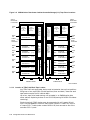
SW800-Series Data Center Cabinet . . . . . . . . . . . . .
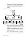
Standard Shelf Configuration . . . . . . . . . . . . . . .
Device Shelf to Controller Port Relationships . .
Location of TZ8x7 Half-Rack Tape Loaders . . . .
Use of an Upper Controller Shelf . . . . . . . . . . . .
Number of Devices . . . . . . . . . . . . . . . . . . . . . . .
Maximum Number of Device Shelves . . . . . . . . .
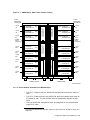
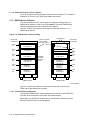
SW500-Series Cabinets . . . . . . . . . . . . . . . . . . . . . .
Standard Shelf Configuration . . . . . . . . . . . . . . .
Device Shelf to Controller Port Relationships . .
Location of TZ8x7 Half-Rack Tape Loaders . . . .
Use of a Second Controller Shelf . . . . . . . . . . . .
SW300-Series Deskside RAID Enclosure . . . . . . . . .
BA350-Series Shelves . . . . . . . . . . . . . . . . . . . . . . . . . . .
Device Placement . . . . . . . . . . . . . . . . . . . . . . . . . . . . . .
3½-Inch SBB Restrictions, BA350–SB . . . . . . . . . . .
5¼-Inch SBB Restrictions, BA350–SB . . . . . . . . . . .
Table Conventions . . . . . . . . . . . . . . . . . . . . . . . . . .
3½-Inch SBBs . . . . . . . . . . . . . . . . . . . . . . . . . . . . .
5¼-Inch SBBs . . . . . . . . . . . . . . . . . . . . . . . . . . . . .
Intermixing 5¼-Inch and 3½-Inch SBBs, BA350–SB
Atypical Configurations . . . . . . . . . . . . . . . . . . . . . .
SW300 Deskside RAID Configuration . . . . . . . . . . .
Controllers . . . . . . . . . . . . . . . . . . . . . . . . . . . . . . . . . .
Nonredundant Controllers . . . . . . . . . . . . . . . . . . . .
Dual-Redundant Controller Guidelines . . . . . . . . . .
Optimal Performance Configuration . . . . . . . . . . . . .
Optimal Availability Configuration . . . . . . . . . . . . .
Host Considerations . . . . . . . . . . . . . . . . . . . . . . . . . . . .
Host Cables . . . . . . . . . . . . . . . . . . . . . . . . . . . . . . .
Host Adapters . . . . . . . . . . . . . . . . . . . . . . . . . . . . .
.
.
.
.
.
.
.
.
.
.
.
.
.
.
.
.
.
.
.
.
.
.
.
.
.
.
.
.
.
.
.
.
.
.
.
.
.
.
.
.
.
.
.
.
.
.
.
.
.
.
.
.
.
.
.
.
.
.
.
.
.
.
.
.
.
.
.
.
.
.
.
.
.
.
.
.
.
.
.
.
.
.
.
.
.
.
.
.
.
.
.
.
.
.
.
.
.
.
.
.
.
.
.
.
.
.
.
.
.
.
.
.
.
.
.
.
.
.
.
.
.
.
.
.
.
.
.
.
.
.
.
.
.
.
.
.
.
.
.
.
.
.
.
.
.
.
.
.
.
.
.
.
.
.
.
.
.
.
.
.
.
.
.
.
.
.
.
.
.
.
.
.
.
.
.
.
.
.
.
.
.
.
.
.
.
.
.
.
.
.
.
.
4 Controller Operation and Initial Configuration
4.1
Initialization . . . . . . . . . . . . . . . . . . . . . . . . . . . . . . . . . . . . . . . . . . . . . . .
4.1.1
Controller Initialization . . . . . . . . . . . . . . . . . . . . . . . . . . . . . . . . . . . .
4.1.2
Dual-Redundant Configuration Initialization . . . . . . . . . . . . . . . . . . . .
4.1.3
Subsystem Initialization . . . . . . . . . . . . . . . . . . . . . . . . . . . . . . . . . . .
4.2
Operator Control Panel . . . . . . . . . . . . . . . . . . . . . . . . . . . . . . . . . . . . . . .
4.3
Maintenance Terminal . . . . . . . . . . . . . . . . . . . . . . . . . . . . . . . . . . . . . . . .
4.4
Command Line Interpreter . . . . . . . . . . . . . . . . . . . . . . . . . . . . . . . . . . . .
4.4.1
Accessing the CLI . . . . . . . . . . . . . . . . . . . . . . . . . . . . . . . . . . . . . . . .
4.4.2
Exiting the CLI . . . . . . . . . . . . . . . . . . . . . . . . . . . . . . . . . . . . . . . . . .
4.4.3
Command Sets . . . . . . . . . . . . . . . . . . . . . . . . . . . . . . . . . . . . . . . . . . .
4.4.4
Initial Configuration (Nonredundant Controller) . . . . . . . . . . . . . . . . .
4.4.5
Initial Configuration (Dual-Redundant Controllers) . . . . . . . . . . . . . . .
4.4.6
Configuring Storage Devices . . . . . . . . . . . . . . . . . . . . . . . . . . . . . . . .
4.5
Acceptance Test . . . . . . . . . . . . . . . . . . . . . . . . . . . . . . . . . . . . . . . . . . . . .
4.6
Virtual Terminal (HSJ- and HSD-Series) . . . . . . . . . . . . . . . . . . . . . . . . . .
4.7
Virtual Terminal (HSZ-Series) . . . . . . . . . . . . . . . . . . . . . . . . . . . . . . . . . .
4.8
VAXcluster Console System . . . . . . . . . . . . . . . . . . . . . . . . . . . . . . . . . . . .
4.9
Operating Systems . . . . . . . . . . . . . . . . . . . . . . . . . . . . . . . . . . . . . . . . . . .
4.9.1
Controller Disks as System Initialization Disks . . . . . . . . . . . . . . . . . .
4.9.2
Operating System Nodes (OpenVMS) . . . . . . . . . . . . . . . . . . . . . . . . . .
4.9.3
AUTOGEN.COM (OpenVMS) . . . . . . . . . . . . . . . . . . . . . . . . . . . . . . . .
4.9.4
Other Conditions (OpenVMS) . . . . . . . . . . . . . . . . . . . . . . . . . . . . . . .
4.10
Failover . . . . . . . . . . . . . . . . . . . . . . . . . . . . . . . . . . . . . . . . . . . . . . . . . . .
4.10.1
Setting Failover . . . . . . . . . . . . . . . . . . . . . . . . . . . . . . . . . . . . . . . . . .
4.10.2
Failing Over . . . . . . . . . . . . . . . . . . . . . . . . . . . . . . . . . . . . . . . . . . . . .
4.10.3
Exiting Failover . . . . . . . . . . . . . . . . . . . . . . . . . . . . . . . . . . . . . . . . . .
4.10.3.1
Before Failover Occurs . . . . . . . . . . . . . . . . . . . . . . . . . . . . . . . . . .
4.10.3.2
After Failover Occurs . . . . . . . . . . . . . . . . . . . . . . . . . . . . . . . . . . .
4.10.4
Failover Setup Mismatch . . . . . . . . . . . . . . . . . . . . . . . . . . . . . . . . . . .
4.10.5
Preferred Paths (HSJ- and HSD-Series) . . . . . . . . . . . . . . . . . . . . . . .
4.10.6
Preferred Paths (HSZ-Series) . . . . . . . . . . . . . . . . . . . . . . . . . . . . . . . .
4.11
Moving Devices Between Controllers . . . . . . . . . . . . . . . . . . . . . . . . . . . . .
4.12
Moving Devices Under the Same Controller . . . . . . . . . . . . . . . . . . . . . . .
4.13
Command Disks (HSJ- and HSD-Series) . . . . . . . . . . . . . . . . . . . . . . . . . .
4.13.1
Uses for Command Disks . . . . . . . . . . . . . . . . . . . . . . . . . . . . . . . . . . .
4.13.2
Creating a Command Disk . . . . . . . . . . . . . . . . . . . . . . . . . . . . . . . . . .
4.13.2.1
Controller Setup . . . . . . . . . . . . . . . . . . . . . . . . . . . . . . . . . . . . . . .
4.13.2.2
Host Setup . . . . . . . . . . . . . . . . . . . . . . . . . . . . . . . . . . . . . . . . . . .
4.13.3
Communicating with a Command Disk . . . . . . . . . . . . . . . . . . . . . . . .
4.13.4
Performance . . . . . . . . . . . . . . . . . . . . . . . . . . . . . . . . . . . . . . . . . . . . .
4.13.5
Maintenance . . . . . . . . . . . . . . . . . . . . . . . . . . . . . . . . . . . . . . . . . . . .
4–1
4–1
4–1
4–2
4–2
4–2
4–2
4–3
4–3
4–4
4–4
4–6
4–9
4–10
4–10
4–11
4–11
4–11
4–12
4–13
4–13
4–14
4–15
4–16
4–17
4–17
4–17
4–17
4–18
4–18
4–18
4–19
4–20
4–21
4–21
4–21
4–22
4–22
4–24
4–24
4–24
5 Fault Isolation and Error Analysis
5.1
5.2
5.3
5.4
5.4.1
5.4.2
5.5
5.5.1
5.5.2
Special Considerations . . .
Troubleshooting Basics . . . .
Types of Error Reporting . .
Operator Control Panel . . .
Normal Operation . . . .
Fault Notification . . . . .
Device LEDs . . . . . . . . . . .
Storage SBB Status . .
Device Shelf Status and
.................
.................
.................
.................
.................
.................
.................
.................
Power Supply Status
.
.
.
.
.
.
.
.
.
.
.
.
.
.
.
.
.
.
.
.
.
.
.
.
.
.
.
.
.
.
.
.
.
.
.
.
.
.
.
.
.
.
.
.
.
.
.
.
.
.
.
.
.
.
.
.
.
.
.
.
.
.
.
.
.
.
.
.
.
.
.
.
.
.
.
.
.
.
.
.
.
.
.
.
.
.
.
.
.
.
.
.
.
.
.
.
.
.
.
.
.
.
.
.
.
.
.
.
.
.
.
.
.
.
.
.
.
.
.
.
.
.
.
.
.
.
.
.
.
.
.
.
.
.
.
.
.
.
.
.
.
.
.
.
.
.
.
.
.
.
.
.
.
.
.
.
.
.
.
.
.
.
.
.
.
.
.
.
.
.
.
5–1
5–2
5–3
5–3
5–3
5–4
5–9
5–9
5–10
v
.
.
.
.
.
.
.
.
.
.
.
.
5–13
5–13
5–16
5–17
5–25
5–26
5–26
5–26
5–27
5–27
5–28
5–28
6.1
Initialization . . . . . . . . . . . . . . . . . . . . . . . . . . . . . . . . . . . . . . . . . . . . . . .
6.1.1
Built-In Self-Test . . . . . . . . . . . . . . . . . . . . . . . . . . . . . . . . . . . . . . . . .
6.1.2
Core Module Integrity Self-Test . . . . . . . . . . . . . . . . . . . . . . . . . . . . . .
6.1.3
Module Integrity Self-Test DAEMON . . . . . . . . . . . . . . . . . . . . . . . . . .
6.1.3.1
Self-Test . . . . . . . . . . . . . . . . . . . . . . . . . . . . . . . . . . . . . . . . . . . . .
6.2
Disk Inline Exerciser (HSJ- and HSD-Series) . . . . . . . . . . . . . . . . . . . . . .
6.2.1
Invoking DILX . . . . . . . . . . . . . . . . . . . . . . . . . . . . . . . . . . . . . . . . . . .
6.2.2
Interrupting DILX Execution . . . . . . . . . . . . . . . . . . . . . . . . . . . . . . . .
6.2.3
DILX Tests . . . . . . . . . . . . . . . . . . . . . . . . . . . . . . . . . . . . . . . . . . . . . .
6.2.3.1
Basic Function Test—DILX . . . . . . . . . . . . . . . . . . . . . . . . . . . . . .
6.2.3.2
User-Defined Test—DILX . . . . . . . . . . . . . . . . . . . . . . . . . . . . . . . .
6.2.4
DILX Test Definition Questions . . . . . . . . . . . . . . . . . . . . . . . . . . . . . .
6.2.5
DILX Output Messages . . . . . . . . . . . . . . . . . . . . . . . . . . . . . . . . . . . .
6.2.6
DILX End Message Display . . . . . . . . . . . . . . . . . . . . . . . . . . . . . . . . .
6.2.7
DILX Error Information Packet Displays . . . . . . . . . . . . . . . . . . . . . . .
6.2.8
DILX Data Patterns . . . . . . . . . . . . . . . . . . . . . . . . . . . . . . . . . . . . . . .
6.2.9
DILX Examples . . . . . . . . . . . . . . . . . . . . . . . . . . . . . . . . . . . . . . . . . .
6.2.9.1
DILX Example—Using All Defaults . . . . . . . . . . . . . . . . . . . . . . . .
6.2.9.2
DILX Example—Using All Functions . . . . . . . . . . . . . . . . . . . . . . .
6.2.9.3
DILX Examples—Auto-Configure with All Units . . . . . . . . . . . . . .
6.2.10
Interpreting the DILX Performance Summaries . . . . . . . . . . . . . . . . .
6.2.11
DILX Abort Codes . . . . . . . . . . . . . . . . . . . . . . . . . . . . . . . . . . . . . . . .
6.2.12
DILX Error Codes . . . . . . . . . . . . . . . . . . . . . . . . . . . . . . . . . . . . . . . .
6.3
Tape Inline Exerciser (HSJ- and HSD-Series) . . . . . . . . . . . . . . . . . . . . . .
6.3.1
Invoking TILX . . . . . . . . . . . . . . . . . . . . . . . . . . . . . . . . . . . . . . . . . . .
6.3.2
Interrupting TILX Execution . . . . . . . . . . . . . . . . . . . . . . . . . . . . . . . .
6.3.3
TILX Tests . . . . . . . . . . . . . . . . . . . . . . . . . . . . . . . . . . . . . . . . . . . . . .
6.3.3.1
Basic Function Test—TILX . . . . . . . . . . . . . . . . . . . . . . . . . . . . . .
6.3.3.2
User-Defined Test—TILX . . . . . . . . . . . . . . . . . . . . . . . . . . . . . . . .
6.3.3.3
Read Only Test—TILX . . . . . . . . . . . . . . . . . . . . . . . . . . . . . . . . . .
6.3.4
TILX Test Definition Questions . . . . . . . . . . . . . . . . . . . . . . . . . . . . . .
6.3.5
TILX Output Messages . . . . . . . . . . . . . . . . . . . . . . . . . . . . . . . . . . . .
6.3.6
TILX End Message Display . . . . . . . . . . . . . . . . . . . . . . . . . . . . . . . . .
6.3.7
TILX Error Information Packet Displays . . . . . . . . . . . . . . . . . . . . . . .
6.3.8
TILX Data Patterns . . . . . . . . . . . . . . . . . . . . . . . . . . . . . . . . . . . . . . .
6.3.9
TILX Examples . . . . . . . . . . . . . . . . . . . . . . . . . . . . . . . . . . . . . . . . . .
6.3.9.1
TILX Example—Using All Defaults . . . . . . . . . . . . . . . . . . . . . . . .
6.3.9.2
TILX Example—Using All Functions . . . . . . . . . . . . . . . . . . . . . . .
6.3.10
Interpreting the TILX Performance Summaries . . . . . . . . . . . . . . . . . .
6–1
6–2
6–2
6–4
6–5
6–7
6–7
6–8
6–8
6–8
6–9
6–9
6–15
6–19
6–19
6–22
6–23
6–23
6–24
6–26
6–27
6–29
6–29
6–30
6–30
6–31
6–31
6–31
6–32
6–32
6–32
6–37
6–41
6–41
6–43
6–44
6–44
6–45
6–47
5.6
5.6.1
5.6.2
5.7
5.7.1
5.8
5.8.1
5.8.2
5.9
5.9.1
5.9.2
5.9.3
Environmental Monitor Unit—SW300 Cabinets
Fault Notification . . . . . . . . . . . . . . . . . . . . .
HSZ40-Bx Fault Notification . . . . . . . . . . . .
Event Messages . . . . . . . . . . . . . . . . . . . . . . . . .
Interactive CLI Messages . . . . . . . . . . . . . . .
Other Spontaneous Messages . . . . . . . . . . . . . . .
Last Failure Logging Messages . . . . . . . . . .
Event Logging Messages . . . . . . . . . . . . . . .
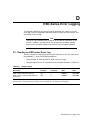
Host Error Logs . . . . . . . . . . . . . . . . . . . . . . . . .
Translation Utilities . . . . . . . . . . . . . . . . . . .
Fault Management Utility . . . . . . . . . . . . . .
Host Error Log Translation . . . . . . . . . . . . .
.
.
.
.
.
.
.
.
.
.
.
.
.
.
.
.
.
.
.
.
.
.
.
.
.
.
.
.
.
.
.
.
.
.
.
.
.
.
.
.
.
.
.
.
.
.
.
.
.
.
.
.
.
.
.
.
.
.
.
.
.
.
.
.
.
.
.
.
.
.
.
.
.
.
.
.
.
.
.
.
.
.
.
.
.
.
.
.
.
.
.
.
.
.
.
.
.
.
.
.
.
.
.
.
.
.
.
.
.
.
.
.
.
.
.
.
.
.
.
.
.
.
.
.
.
.
.
.
.
.
.
.
.
.
.
.
.
.
.
.
.
.
.
.
.
.
.
.
.
.
.
.
.
.
.
.
.
.
.
.
.
.
.
.
.
.
.
.
.
.
.
.
.
.
.
.
.
.
.
.
.
.
.
.
.
.
.
.
.
.
.
.
.
.
.
.
.
.
.
.
.
.
.
.
.
.
.
.
.
.
.
.
.
.
.
.
.
.
.
.
.
.
.
.
.
.
.
.
6 Diagnostics, Exercisers, and Utilities
vi
6.3.11
6.3.12
6.4
6.4.1
6.4.2
6.4.3
6.4.3.1
6.4.3.2
6.4.4
6.4.5
6.4.6
6.4.7
6.4.8
6.4.9
6.4.10
6.4.11
6.5
6.5.1
6.5.2
6.5.3
6.5.4
6.6
6.6.1
6.6.2
6.7
6.7.1
6.7.2
6.7.3
6.7.4
6.7.5
6.7.6
6.7.7
6.7.8
6.7.9
6.7.10
6.7.11
6.7.12
6.7.13
6.8
6.8.1
6.8.2
6.8.2.1
6.8.3
6.8.3.1
6.8.3.2
6.8.3.3
6.8.3.4
6.8.3.5
6.8.3.6
6.8.3.7
6.9
6.9.1
6.9.2
6.9.3
TILX Abort Codes . . . . . . . . . . . . . . . . . . . . . . .
TILX Error Codes . . . . . . . . . . . . . . . . . . . . . . .
Disk Inline Exerciser (HSZ-Series) . . . . . . . . . . . . .
Invoking DILX . . . . . . . . . . . . . . . . . . . . . . . . . .
Interrupting DILX Execution . . . . . . . . . . . . . . .
DILX Tests . . . . . . . . . . . . . . . . . . . . . . . . . . . . .
Basic Function Test—DILX . . . . . . . . . . . . .
User-Defined Test—DILX . . . . . . . . . . . . . . .
DILX Test Definition Questions . . . . . . . . . . . . .
DILX Output Messages . . . . . . . . . . . . . . . . . . .
DILX Sense Data Display . . . . . . . . . . . . . . . . .
DILX Deferred Error Display . . . . . . . . . . . . . . .
DILX Data Patterns . . . . . . . . . . . . . . . . . . . . . .
Interpreting the DILX Performance Summaries
DILX Abort Codes . . . . . . . . . . . . . . . . . . . . . . .
DILX Error Codes . . . . . . . . . . . . . . . . . . . . . . .
VTDPY Utility . . . . . . . . . . . . . . . . . . . . . . . . . . . . .
How to Run VTDPY . . . . . . . . . . . . . . . . . . . . . .
Using the VTDPY Control Keys . . . . . . . . . . . . .
Using the VTDPY Command Line . . . . . . . . . .
How to Interpret the VTDPY Display Fields . . .
CONFIG Utility . . . . . . . . . . . . . . . . . . . . . . . . . . . .
CONFIG Conventions . . . . . . . . . . . . . . . . . . . .
Running the CONFIG Utility . . . . . . . . . . . . . . .
Configuration Menu . . . . . . . . . . . . . . . . . . . . . . . . .
Restrictions . . . . . . . . . . . . . . . . . . . . . . . . . . . .
Main Menu . . . . . . . . . . . . . . . . . . . . . . . . . . . .
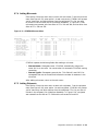
Adding Devices . . . . . . . . . . . . . . . . . . . . . . . . .
Adding Mirrorsets . . . . . . . . . . . . . . . . . . . . . . .
Adding Stripesets . . . . . . . . . . . . . . . . . . . . . . . .
Adding RAIDsets . . . . . . . . . . . . . . . . . . . . . . . .
Adding to Sparesets . . . . . . . . . . . . . . . . . . . . . .
Adding Passthroughs (HSJ- and HSD-Series) . .
Initializing Containers . . . . . . . . . . . . . . . . . . . .
Adding Units . . . . . . . . . . . . . . . . . . . . . . . . . . .
Terminal Setup . . . . . . . . . . . . . . . . . . . . . . . . .
Messages . . . . . . . . . . . . . . . . . . . . . . . . . . . . . .
Exiting CFMENU . . . . . . . . . . . . . . . . . . . . . . .
Code Load/Code Patch Utility . . . . . . . . . . . . . . . . .
Invoking the CLCP Utility . . . . . . . . . . . . . . . . .
Code Load . . . . . . . . . . . . . . . . . . . . . . . . . . . . .
Using Code Load . . . . . . . . . . . . . . . . . . . . .
Code Patching . . . . . . . . . . . . . . . . . . . . . . . . . .
Code Patch Considerations . . . . . . . . . . . . . .
Using Code Load . . . . . . . . . . . . . . . . . . . . .
Entering a Patch . . . . . . . . . . . . . . . . . . . . .
Listing Patches . . . . . . . . . . . . . . . . . . . . . .
Deleting a Patch . . . . . . . . . . . . . . . . . . . . .
Messages . . . . . . . . . . . . . . . . . . . . . . . . . . .
Exiting Code Patch . . . . . . . . . . . . . . . . . . .
Firmware Licensing System (FLS) . . . . . . . . . . . . . .
Enabling Options . . . . . . . . . . . . . . . . . . . . . . . .
Disabling Options . . . . . . . . . . . . . . . . . . . . . . .
License Key . . . . . . . . . . . . . . . . . . . . . . . . . . . .
.
.
.
.
.
.
.
.
.
.
.
.
.
.
.
.
.
.
.
.
.
.
.
.
.
.
.
.
.
.
.
.
.
.
.
.
.
.
.
.
.
.
.
.
.
.
.
.
.
.
.
.
.
.
.
.
.
.
.
.
.
.
.
.
.
.
.
.
.
.
.
.
.
.
.
.
.
.
.
.
.
.
.
.
.
.
.
.
.
.
.
.
.
.
.
.
.
.
.
.
.
.
.
.
.
.
.
.
.
.
.
.
.
.
.
.
.
.
.
.
.
.
.
.
.
.
.
.
.
.
.
.
.
.
.
.
.
.
.
.
.
.
.
.
.
.
.
.
.
.
.
.
.
.
.
.
.
.
.
.
.
.
.
.
.
.
.
.
.
.
.
.
.
.
.
.
.
.
.
.
.
.
.
.
.
.
.
.
.
.
.
.
.
.
.
.
.
.
.
.
.
.
.
.
.
.
.
.
.
.
.
.
.
.
.
.
.
.
.
.
.
.
.
.
.
.
.
.
.
.
.
.
.
.
.
.
.
.
.
.
.
.
.
.
.
.
.
.
.
.
.
.
.
.
.
.
.
.
.
.
.
.
.
.
.
.
.
.
.
.
.
.
.
.
.
.
.
.
.
.
.
.
.
.
.
.
.
.
.
.
.
.
.
.
.
.
.
.
.
.
.
.
.
.
.
.
.
.
.
.
.
.
.
.
.
.
.
.
.
.
.
.
.
.
.
.
.
.
.
.
.
.
.
.
.
.
.
.
.
.
.
.
.
.
.
.
.
.
.
.
.
.
.
.
.
.
.
.
.
.
.
.
.
.
.
.
.
.
.
.
.
.
.
.
.
.
.
.
.
.
.
.
.
.
.
.
.
.
.
.
.
.
.
.
.
.
.
.
.
.
.
.
.
.
.
.
.
.
.
.
.
.
.
.
.
.
.
.
.
.
.
.
.
.
.
.
.
.
.
.
.
.
.
.
.
.
.
.
.
.
.
.
.
.
.
.
.
.
.
.
.
.
.
.
.
.
.
.
.
.
.
.
.
.
.
.
.
.
.
.
.
.
.
.
.
.
.
.
.
.
.
.
.
.
.
.
.
.
.
.
.
.
.
.
.
.
.
.
.
.
.
.
.
.
.
.
.
.
.
.
.
.
.
.
.
.
.
.
.
.
.
.
.
.
.
.
.
.
.
.
.
.
.
.
.
.
.
.
.
.
.
.
.
.
.
.
.
.
.
.
.
.
.
.
.
.
.
.
.
.
.
.
.
.
.
.
.
.
.
.
.
.
.
.
.
.
.
.
.
.
.
.
.
.
.
.
.
.
.
.
.
.
.
.
.
.
.
.
.
.
.
.
.
.
.
.
.
.
.
.
.
.
.
.
.
.
.
.
.
.
.
.
.
.
.
.
.
.
.
.
.
.
.
.
.
.
.
.
.
.
.
.
.
.
.
.
.
.
.
.
.
.
.
.
.
.
.
.
.
.
.
.
.
.
.
.
.
.
.
.
.
.
.
.
.
.
.
.
.
.
.
.
.
.
.
.
.
.
.
.
.
.
.
.
.
.
.
.
.
.
.
.
.
.
.
.
.
.
.
.
.
.
.
.
.
.
.
.
.
.
.
.
.
.
.
.
.
.
.
.
.
.
.
.
.
.
.
.
.
.
.
.
.
.
.
.
.
.
.
.
.
.
.
.
.
.
.
.
.
.
.
.
.
.
.
.
.
.
.
.
.
.
.
.
.
.
.
.
.
.
.
.
.
.
.
.
.
.
.
.
.
.
.
.
.
.
.
.
.
.
.
.
.
.
.
.
.
.
.
.
.
.
.
.
.
.
.
.
.
.
.
.
.
.
.
.
.
.
.
.
.
.
.
.
.
.
.
.
.
.
.
.
.
.
.
.
.
.
.
.
.
.
.
.
.
.
.
.
.
.
.
.
.
.
.
.
.
.
.
.
.
.
.
.
.
.
.
.
.
.
.
.
.
.
.
.
.
.
.
.
.
.
.
.
.
.
.
.
.
.
.
.
.
.
.
.
.
.
.
.
.
.
.
.
.
.
.
.
6–48
6–49
6–50
6–50
6–50
6–51
6–51
6–52
6–52
6–57
6–61
6–61
6–61
6–62
6–64
6–65
6–66
6–66
6–66
6–67
6–67
6–98
6–98
6–98
6–100
6–100
6–100
6–101
6–103
6–103
6–104
6–105
6–105
6–107
6–108
6–109
6–109
6–112
6–113
6–113
6–113
6–114
6–115
6–115
6–115
6–116
6–117
6–118
6–119
6–120
6–121
6–121
6–121
6–121
vii
6.9.4
Using the Menu . . . . .
6.9.5
Example . . . . . . . . . . .
6.9.6
Messages . . . . . . . . . .
6.10
Fault Management Utility
6.10.1
SET Command . . . . . .
6.10.2
SHOW Command . . . .
6.10.3
DESCRIBE Command
6.10.4
EXIT Command . . . . .
6.10.5
Examples . . . . . . . . .
6.11
CLONE Utility . . . . . . . . .
....
....
....
...
....
....
....
....
....
....
.
.
.
.
.
.
.
.
.
.
.
.
.
.
.
.
.
.
.
.
.
.
.
.
.
.
.
.
.
.
.
.
.
.
.
.
.
.
.
.
.
.
.
.
.
.
.
.
.
.
.
.
.
.
.
.
.
.
.
.
.
.
.
.
.
.
.
.
.
.
.
.
.
.
.
.
.
.
.
.
.
.
.
.
.
.
.
.
.
.
.
.
.
.
.
.
.
.
.
.
.
.
.
.
.
.
.
.
.
.
.
.
.
.
.
.
.
.
.
.
.
.
.
.
.
.
.
.
.
.
.
.
.
.
.
.
.
.
.
.
.
.
.
.
.
.
.
.
.
.
.
.
.
.
.
.
.
.
.
.
.
.
.
.
.
.
.
.
.
.
.
.
.
.
.
.
.
.
.
.
.
.
.
.
.
.
.
.
.
.
.
.
.
.
.
.
.
.
.
.
.
.
.
.
.
.
.
.
.
.
.
.
.
.
.
.
.
.
.
.
.
.
.
.
.
.
.
.
.
.
.
.
.
.
.
.
.
.
.
.
.
.
.
.
.
.
.
.
.
.
.
.
.
.
.
.
.
.
.
.
.
.
.
.
.
.
.
.
.
.
.
.
.
.
.
.
.
.
.
.
.
.
.
.
.
.
.
.
.
.
.
.
.
.
.
.
.
.
.
.
.
.
.
.
.
.
.
.
.
.
.
.
.
.
.
.
.
.
.
.
.
.
.
.
.
.
.
.
.
.
6–121
6–122
6–124
6–125
6–125
6–128
6–129
6–130
6–130
6–134
...
...
7–2
7–3
7 Removing and Replacing Field Replaceable Units
7.1
7.2
7.3
7.4
7.5
7.5.1
7.5.1.1
7.5.1.2
7.5.1.3
7.5.1.4
7.5.1.5
7.5.2
7.5.2.1
7.5.2.2
7.5.2.3
7.5.2.4
7.5.2.5
7.5.3
7.6
7.6.1
7.6.1.1
7.6.1.2
7.6.1.3
7.6.1.4
7.6.2
7.6.2.1
7.6.2.2
7.6.2.3
7.6.2.4
7.6.2.5
7.6.2.6
7.6.2.7
7.6.2.8
7.7
7.7.1
7.7.2
7.7.3
7.7.4
7.8
7.8.1
viii
Electrostatic Discharge Protection . . . . . . . . . . . . . . . . . . . . . . . . . . . .
Diagnosing Subsystem Errors . . . . . . . . . . . . . . . . . . . . . . . . . . . . . . .
Using the Controller SHUTDOWN Command to Turn Off Controller
Power . . . . . . . . . . . . . . . . . . . . . . . . . . . . . . . . . . . . . . . . . . . . . . . . . .
Using DISMOUNT or SHUTDOWN for Device Moves . . . . . . . . . . . . .
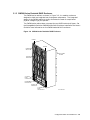
Controller Modules . . . . . . . . . . . . . . . . . . . . . . . . . . . . . . . . . . . . . . . .
Replacing a Nonredundant Controller . . . . . . . . . . . . . . . . . . . . . .
Tools Required . . . . . . . . . . . . . . . . . . . . . . . . . . . . . . . . . . . . .
Precautions . . . . . . . . . . . . . . . . . . . . . . . . . . . . . . . . . . . . . . .
Removing the Controller Module . . . . . . . . . . . . . . . . . . . . . . .
Replacing/Installing the Controller Module . . . . . . . . . . . . . . .
Restoring Initial Parameters (Nonredundant Controller) . . . . .
Replacing One Dual-Redundant Controller . . . . . . . . . . . . . . . . . .
Tools Required . . . . . . . . . . . . . . . . . . . . . . . . . . . . . . . . . . . . .
Precautions . . . . . . . . . . . . . . . . . . . . . . . . . . . . . . . . . . . . . . .
Removing the Controller Module . . . . . . . . . . . . . . . . . . . . . . .
Replacing/Installing the Controller Module . . . . . . . . . . . . . . .
Restoring Initial Parameters (One Dual-redundant Controller)
Replacing Both Dual-Redundant Controllers . . . . . . . . . . . . . . . . .
Cache Module . . . . . . . . . . . . . . . . . . . . . . . . . . . . . . . . . . . . . . . . . . .
Replacing a Read Cache Module . . . . . . . . . . . . . . . . . . . . . . . . . .
Tools Required . . . . . . . . . . . . . . . . . . . . . . . . . . . . . . . . . . . . .
Precautions . . . . . . . . . . . . . . . . . . . . . . . . . . . . . . . . . . . . . . .
Removing the Read Cache Module . . . . . . . . . . . . . . . . . . . . . .
Replacing/Installing a Read Cache Module . . . . . . . . . . . . . . .
Replacing a Write-back Cache Module . . . . . . . . . . . . . . . . . . . . . .
Tools Required . . . . . . . . . . . . . . . . . . . . . . . . . . . . . . . . . . . . .
Precautions . . . . . . . . . . . . . . . . . . . . . . . . . . . . . . . . . . . . . . .
Removing a Write-Back Cache Module . . . . . . . . . . . . . . . . . . .
Upgrading Cache Modules . . . . . . . . . . . . . . . . . . . . . . . . . . . .
Removing the Battery . . . . . . . . . . . . . . . . . . . . . . . . . . . . . . .
Disposing of the Battery . . . . . . . . . . . . . . . . . . . . . . . . . . . . .
Replacing/Installing the Battery . . . . . . . . . . . . . . . . . . . . . . .
Replacing/Installing the Module . . . . . . . . . . . . . . . . . . . . . . . .
Program Card . . . . . . . . . . . . . . . . . . . . . . . . . . . . . . . . . . . . . . . . . . .
Tools Required . . . . . . . . . . . . . . . . . . . . . . . . . . . . . . . . . . . . . . . .
Precautions . . . . . . . . . . . . . . . . . . . . . . . . . . . . . . . . . . . . . . . . . .
Removing the Program Card . . . . . . . . . . . . . . . . . . . . . . . . . . . . .
Replacing/Installing the Program Card . . . . . . . . . . . . . . . . . . . . .
External CI Cables (HSJ-Series) . . . . . . . . . . . . . . . . . . . . . . . . . . . . .
Tools Required . . . . . . . . . . . . . . . . . . . . . . . . . . . . . . . . . . . . . . . .
.
.
.
.
.
.
.
.
.
.
.
.
.
.
.
.
.
.
.
.
.
.
.
.
.
.
.
.
.
.
.
.
.
.
.
.
.
.
.
.
.
.
.
.
.
.
.
.
.
.
.
.
.
.
.
.
.
.
.
.
.
.
.
.
.
.
.
.
.
.
.
.
.
.
.
.
.
.
.
.
.
.
.
.
.
.
.
.
.
.
.
.
.
.
.
.
.
.
.
.
.
.
.
.
.
.
.
.
.
.
.
.
.
.
7–3
7–5
7–6
7–6
7–6
7–6
7–7
7–11
7–13
7–15
7–16
7–16
7–16
7–18
7–19
7–22
7–24
7–24
7–24
7–24
7–24
7–24
7–25
7–25
7–25
7–25
7–26
7–31
7–33
7–33
7–33
7–35
7–35
7–35
7–36
7–37
7–38
7–38
7.8.2
Precautions . . . . . . . . . . . . . . . . . . . . . . . . . .
7.8.3
Removing the Cable . . . . . . . . . . . . . . . . . . . .
7.8.4
Replacing/Installing the Cable . . . . . . . . . . . .
7.9
Internal CI Cables (HSJ-Series) . . . . . . . . . . . . . .
7.9.1
Tools Required . . . . . . . . . . . . . . . . . . . . . . . .
7.9.2
Precautions . . . . . . . . . . . . . . . . . . . . . . . . . .
7.9.3
Removing the Cable . . . . . . . . . . . . . . . . . . . .
7.9.4
Replacing/Installing the Cable . . . . . . . . . . . .
7.10
DSSI Host Cables (HSD-Series) . . . . . . . . . . . . . .
7.10.1
Tools Required . . . . . . . . . . . . . . . . . . . . . . . .
7.10.2
Precautions . . . . . . . . . . . . . . . . . . . . . . . . . .
7.10.3
Removing the Cable . . . . . . . . . . . . . . . . . . . .
7.10.4
Replacing/Installing the Cable . . . . . . . . . . . .
7.11
SCSI Host Cables (HSZ-Series) . . . . . . . . . . . . . .
7.11.1
Tools Required . . . . . . . . . . . . . . . . . . . . . . . .
7.11.2
Precautions . . . . . . . . . . . . . . . . . . . . . . . . . .
7.11.3
Removing the Cable . . . . . . . . . . . . . . . . . . . .
7.11.4
Replacing/Installing the Cable . . . . . . . . . . . .
7.12
SCSI Device Port Cables . . . . . . . . . . . . . . . . . . .
7.12.1
Tools Required . . . . . . . . . . . . . . . . . . . . . . . .
7.12.2
Precautions . . . . . . . . . . . . . . . . . . . . . . . . . .
7.12.3
Removing the Cable . . . . . . . . . . . . . . . . . . . .
7.12.4
Replacing/Installing the Cable . . . . . . . . . . . .
7.13
Blowers . . . . . . . . . . . . . . . . . . . . . . . . . . . . . . . .
7.13.1
Tools Required . . . . . . . . . . . . . . . . . . . . . . . .
7.13.2
Removing the Blower . . . . . . . . . . . . . . . . . . .
7.13.3
Replacing/Installing the Blower . . . . . . . . . . .
7.14
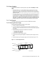
Power Supplies . . . . . . . . . . . . . . . . . . . . . . . . . .
7.14.1
Tools Required . . . . . . . . . . . . . . . . . . . . . . . .
7.14.2
Removing the Power Supply . . . . . . . . . . . . .
7.14.3
Replacing/Installing the Power Supply . . . . .
7.15
Warm Swap . . . . . . . . . . . . . . . . . . . . . . . . . . . . .
7.15.1
Device SBB Warm Swap . . . . . . . . . . . . . . . .
7.15.1.1
Tools Required . . . . . . . . . . . . . . . . . . . . .
7.15.1.2
Removing the Device . . . . . . . . . . . . . . . .
7.15.1.3
Replacing the Device . . . . . . . . . . . . . . . .
7.15.1.4
Restoring the Device to the Configuration
7.15.2
Controller Warm Swap . . . . . . . . . . . . . . . . . .
7.15.2.1
Tools Required . . . . . . . . . . . . . . . . . . . . .
7.15.2.2
Precautions . . . . . . . . . . . . . . . . . . . . . . .
7.15.2.3
Removing the Controller . . . . . . . . . . . . .
7.15.2.4
Replacing the Controller . . . . . . . . . . . . .
7.15.2.5
Restoring Parameters . . . . . . . . . . . . . . .
.
.
.
.
.
.
.
.
.
.
.
.
.
.
.
.
.
.
.
.
.
.
.
.
.
.
.
.
.
.
.
.
.
.
.
.
.
.
.
.
.
.
.
.
.
.
.
.
.
.
.
.
.
.
.
.
.
.
.
.
.
.
.
.
.
.
.
.
.
.
.
.
.
.
.
.
.
.
.
.
.
.
.
.
.
.
.
.
.
.
.
.
.
.
.
.
.
.
.
.
.
.
.
.
.
.
.
.
.
.
.
.
.
.
.
.
.
.
.
.
.
.
.
.
.
.
.
.
.
.
.
.
.
.
.
.
.
.
.
.
.
.
.
.
.
.
.
.
.
.
.
.
.
.
.
.
.
.
.
.
.
.
.
.
.
.
.
.
.
.
.
.
.
.
.
.
.
.
.
.
.
.
.
.
.
.
.
.
.
.
.
.
.
.
.
.
.
.
.
.
.
.
.
.
.
.
.
.
.
.
.
.
.
.
.
.
.
.
.
.
.
.
.
.
.
.
.
.
.
.
.
.
.
.
.
.
.
.
.
.
.
.
.
.
.
.
.
.
.
.
.
.
.
.
.
.
.
.
.
.
.
.
.
.
.
.
.
.
.
.
.
.
.
.
.
.
.
.
.
.
.
.
.
.
.
.
.
.
.
.
.
.
.
.
.
.
.
.
.
.
.
.
.
.
.
.
.
.
.
.
.
.
.
.
.
.
.
.
.
.
.
.
.
.
.
.
.
.
.
.
.
.
.
.
.
.
.
.
.
.
.
.
.
.
.
.
.
.
.
.
.
.
.
.
.
.
.
.
.
.
.
.
.
.
.
.
.
.
.
.
.
.
.
.
.
.
.
.
.
.
.
.
.
.
.
.
.
.
.
.
.
.
.
.
.
.
.
.
.
.
.
.
.
.
.
.
.
.
.
.
.
.
.
.
.
.
.
.
.
.
.
.
.
.
.
.
.
.
.
.
.
.
.
.
.
.
.
.
.
.
.
.
.
.
.
.
.
.
.
.
.
.
.
.
.
.
.
.
.
.
.
.
.
.
.
.
.
.
.
.
.
.
.
.
.
.
.
.
.
.
.
.
.
.
.
.
.
.
.
.
.
.
.
.
.
.
.
.
.
.
.
.
.
.
.
.
.
.
.
.
.
.
.
.
.
.
.
.
.
.
.
.
.
.
.
.
.
.
.
.
.
.
.
.
.
.
.
.
.
.
.
.
.
.
.
.
.
.
.
.
.
.
.
.
.
.
.
.
.
.
.
.
.
.
.
.
.
.
.
.
.
.
.
.
.
.
.
.
.
.
.
.
.
.
.
.
.
.
.
.
.
.
.
.
.
.
.
.
.
.
.
.
.
.
.
.
.
.
.
.
.
.
.
.
.
.
.
.
.
.
.
.
.
.
.
.
.
.
.
.
.
.
.
.
.
.
.
.
.
.
.
.
.
.
.
.
.
.
.
.
.
.
.
.
.
.
.
.
.
.
.
.
.
.
.
.
.
.
.
.
.
.
.
.
.
.
.
.
.
.
.
.
.
.
.
.
.
.
.
.
.
.
.
.
.
.
.
.
.
.
.
.
.
.
.
.
.
.
.
.
.
.
.
.
.
.
.
.
.
.
.
.
.
.
.
.
.
.
.
.
.
.
.
.
.
.
.
.
.
.
.
.
.
.
.
.
.
.
.
.
.
.
.
.
.
.
.
.
.
.
.
.
.
.
.
.
.
.
.
.
.
.
.
.
.
.
.
.
.
.
.
.
.
.
.
.
.
.
.
.
.
.
.
.
.
.
.
.
.
.
.
.
.
.
.
.
.
.
.
.
.
.
.
.
.
.
.
7–38
7–38
7–40
7–41
7–41
7–41
7–41
7–42
7–43
7–43
7–43
7–43
7–44
7–45
7–46
7–46
7–46
7–46
7–47
7–47
7–47
7–47
7–48
7–50
7–51
7–51
7–51
7–53
7–53
7–53
7–54
7–55
7–55
7–56
7–56
7–57
7–59
7–59
7–60
7–60
7–60
7–63
7–64
Controller Field Replaceable Units . . . . . . . . . . . . . . . . . . . . . . . . . . . . . .
Required Tools and Equipment . . . . . . . . . . . . . . . . . . . . . . . . . . . . . . . . .
Related Field Replaceable Units . . . . . . . . . . . . . . . . . . . . . . . . . . . . . . . .
A–1
A–4
A–4
A Field Replaceable Units
A.1
A.2
A.3
ix
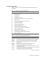
B Command Line Interpreter
B.1
x
CLI Commands . . . . . . . . . . . . . . . . . . . . . . . . . .
ADD CDROM . . . . . . . . . . . . . . . . . . . . . . . . . . . .
ADD DISK . . . . . . . . . . . . . . . . . . . . . . . . . . . . . .
ADD LOADER . . . . . . . . . . . . . . . . . . . . . . . . . . .
ADD MIRRORSET . . . . . . . . . . . . . . . . . . . . . . . .
ADD OPTICAL . . . . . . . . . . . . . . . . . . . . . . . . . .
ADD PASSTHROUGH . . . . . . . . . . . . . . . . . . . . .
ADD RAIDSET . . . . . . . . . . . . . . . . . . . . . . . . . .
ADD SPARESET . . . . . . . . . . . . . . . . . . . . . . . . .
ADD STRIPESET . . . . . . . . . . . . . . . . . . . . . . . .
ADD TAPE . . . . . . . . . . . . . . . . . . . . . . . . . . . . . .
ADD UNIT . . . . . . . . . . . . . . . . . . . . . . . . . . . . . .
CLEAR_ERRORS CLI . . . . . . . . . . . . . . . . . . . . .
CLEAR_ERRORS INVALID_CACHE . . . . . . . . . .
CLEAR_ERRORS LOST_DATA . . . . . . . . . . . . . .
CLEAR_ERRORS UNKNOWN . . . . . . . . . . . . . .
CLEAR_ERRORS UNWRITEABLE_DATA . . . . .
DELETE container-name . . . . . . . . . . . . . . . . . . .
DELETE FAILEDSET . . . . . . . . . . . . . . . . . . . . .
DELETE SPARESET . . . . . . . . . . . . . . . . . . . . . .
DELETE unit-number . . . . . . . . . . . . . . . . . . . . .
DIRECTORY . . . . . . . . . . . . . . . . . . . . . . . . . . . .
EXIT . . . . . . . . . . . . . . . . . . . . . . . . . . . . . . . . . .
HELP . . . . . . . . . . . . . . . . . . . . . . . . . . . . . . . . . .
INITIALIZE . . . . . . . . . . . . . . . . . . . . . . . . . . . . .
LOCATE . . . . . . . . . . . . . . . . . . . . . . . . . . . . . . .
MIRROR disk-device-name1 container-name . . . .
REDUCE disk-device-name1 [disk-device-nameN]
RENAME . . . . . . . . . . . . . . . . . . . . . . . . . . . . . . .
RESTART OTHER_CONTROLLER . . . . . . . . . . .
RESTART THIS_CONTROLLER . . . . . . . . . . . . .
RETRY_ERRORS UNWRITEABLE_DATA . . . . .
RUN . . . . . . . . . . . . . . . . . . . . . . . . . . . . . . . . . . .
SELFTEST OTHER_CONTROLLER . . . . . . . . . .
SELFTEST THIS_CONTROLLER . . . . . . . . . . . .
SET disk-container-name . . . . . . . . . . . . . . . . . . .
SET FAILOVER . . . . . . . . . . . . . . . . . . . . . . . . . .
SET mirrorset-container-name . . . . . . . . . . . . . . .
SET NOFAILOVER . . . . . . . . . . . . . . . . . . . . . . .
SET OTHER_CONTROLLER . . . . . . . . . . . . . . .
SET RAIDset-container-name . . . . . . . . . . . . . . . .
SET THIS_CONTROLLER . . . . . . . . . . . . . . . . .
SET unit-number . . . . . . . . . . . . . . . . . . . . . . . . .
SHOW CDROMS . . . . . . . . . . . . . . . . . . . . . . . . .
SHOW cdrom-container-name . . . . . . . . . . . . . . .
.
.
.
.
.
.
.
.
.
.
.
.
.
.
.
.
.
.
.
.
.
.
.
.
.
.
.
.
.
.
.
.
.
.
.
.
.
.
.
.
.
.
.
.
.
.
.
.
.
.
.
.
.
.
.
.
.
.
.
.
.
.
.
.
.
.
.
.
.
.
.
.
.
.
.
.
.
.
.
.
.
.
.
.
.
.
.
.
.
.
.
.
.
.
.
.
.
.
.
.
.
.
.
.
.
.
.
.
.
.
.
.
.
.
.
.
.
.
.
.
.
.
.
.
.
.
.
.
.
.
.
.
.
.
.
.
.
.
.
.
.
.
.
.
.
.
.
.
.
.
.
.
.
.
.
.
.
.
.
.
.
.
.
.
.
.
.
.
.
.
.
.
.
.
.
.
.
.
.
.
.
.
.
.
.
.
.
.
.
.
.
.
.
.
.
.
.
.
.
.
.
.
.
.
.
.
.
.
.
.
.
.
.
.
.
.
.
.
.
.
.
.
.
.
.
.
.
.
.
.
.
.
.
.
.
.
.
.
.
.
.
.
.
.
.
.
.
.
.
.
.
.
.
.
.
.
.
.
.
.
.
.
.
.
.
.
.
.
.
.
.
.
.
.
.
.
.
.
.
.
.
.
.
.
.
.
.
.
.
.
.
.
.
.
.
.
.
.
.
.
.
.
.
.
.
.
.
.
.
.
.
.
.
.
.
.
.
.
.
.
.
.
.
.
.
.
.
.
.
.
.
.
.
.
.
.
.
.
.
.
.
.
.
.
.
.
.
.
.
.
.
.
.
.
.
.
.
.
.
.
.
.
.
.
.
.
.
.
.
.
.
.
.
.
.
.
.
.
.
.
.
.
.
.
.
.
.
.
.
.
.
.
.
.
.
.
.
.
.
.
.
.
.
.
.
.
.
.
.
.
.
.
.
.
.
.
.
.
.
.
.
.
.
.
.
.
.
.
.
.
.
.
.
.
.
.
.
.
.
.
.
.
.
.
.
.
.
.
.
.
.
.
.
.
.
.
.
.
.
.
.
.
.
.
.
.
.
.
.
.
.
.
.
.
.
.
.
.
.
.
.
.
.
.
.
.
.
.
.
.
.
.
.
.
.
.
.
.
.
.
.
.
.
.
.
.
.
.
.
.
.
.
.
.
.
.
.
.
.
.
.
.
.
.
.
.
.
.
.
.
.
.
.
.
.
.
.
.
.
.
.
.
.
.
.
.
.
.
.
.
.
.
.
.
.
.
.
.
.
.
.
.
.
.
.
.
.
.
.
.
.
.
.
.
.
.
.
.
.
.
.
.
.
.
.
.
.
.
.
.
.
.
.
.
.
.
.
.
.
.
.
.
.
.
.
.
.
.
.
.
.
.
.
.
.
.
.
.
.
.
.
.
.
.
.
.
.
.
.
.
.
.
.
.
.
.
.
.
.
.
.
.
.
.
.
.
.
.
.
.
.
.
.
.
.
.
.
.
.
.
.
.
.
.
.
.
.
.
.
.
.
.
.
.
.
.
.
.
.
.
.
.
.
.
.
.
.
.
.
.
.
.
.
.
.
.
.
.
.
.
.
.
.
.
.
.
.
.
.
.
.
.
.
.
.
.
.
.
.
.
.
.
.
.
.
.
.
.
.
.
.
.
.
.
.
.
.
.
.
.
.
.
.
.
.
.
.
.
.
.
.
.
.
.
.
.
.
.
.
.
.
.
.
.
.
.
.
.
.
.
.
.
.
.
.
.
.
.
.
.
.
.
.
.
.
.
.
.
.
.
.
.
.
.
.
.
.
.
.
.
.
.
.
.
.
.
.
.
.
.
.
.
.
.
.
.
.
.
.
.
.
.
.
.
.
.
.
.
.
.
.
.
.
.
.
.
.
.
.
.
.
.
.
.
.
.
.
.
.
.
.
.
.
.
.
B–1
B–2
B–3
B–5
B–6
B–8
B–10
B–11
B–13
B–14
B–15
B–16
B–27
B–28
B–29
B–30
B–31
B–32
B–33
B–34
B–35
B–36
B–37
B–38
B–39
B–41
B–43
B–45
B–47
B–48
B–50
B–53
B–54
B–55
B–57
B–59
B–60
B–62
B–65
B–66
B–73
B–75
B–82
B–92
B–93
.
.
.
.
.
.
.
.
.
.
.
.
.
.
.
.
.
.
.
.
.
.
.
.
.
.
.
.
.
.
.
.
.
.
.
.
.
.
.
.
.
.
.
.
.
.
.
.
.
.
.
.
.
.
.
.
.
.
.
.
.
.
.
.
.
.
.
.
.
.
.
.
.
.
.
.
.
.
.
.
.
.
.
.
.
.
.
.
.
.
.
.
.
.
.
.
.
.
.
.
.
.
.
.
.
.
.
.
.
.
.
.
.
.
.
.
.
.
.
.
.
.
.
.
.
.
.
.
.
.
.
.
.
.
.
.
.
.
.
.
.
.
.
.
.
.
.
.
.
.
.
.
.
.
.
.
.
.
.
.
.
.
.
.
.
.
.
.
.
.
.
.
.
.
.
.
.
.
.
.
.
.
.
.
.
.
.
.
.
.
.
.
.
.
.
.
.
.
.
.
.
.
.
.
.
.
.
.
.
.
.
.
.
.
.
.
.
.
.
.
.
.
.
.
.
.
.
.
.
.
.
.
.
.
.
.
.
.
.
.
.
.
.
.
.
.
.
.
.
.
.
.
.
.
.
.
.
.
.
.
.
.
.
.
B–94
B–95
B–96
B–97
B–98
B–99
B–100
B–102
B–103
B–104
B–105
B–107
B–108
B–109
B–111
B–112
B–113
B–115
B–117
B–118
B–119
B–120
B–123
B–124
B–125
B–127
B–129
B–130
B–130
B–130
B–150
B–150
B–154
C.1
Reading an HSJ-Series Error Log (ERF) . . . . . . . . . . . . . . . . . . .
C.2
Reading an HSJ-Series Error Log (DECevent) . . . . . . . . . . . . . . .
C.3
Event Log Formats . . . . . . . . . . . . . . . . . . . . . . . . . . . . . . . . . . .
C.3.1
Implementation Dependent Information Area . . . . . . . . . . . .
C.3.2
Common Event Log Fields . . . . . . . . . . . . . . . . . . . . . . . . . . .
C.3.2.1
CI Host Interconnect Services Common Event Log Fields
C.3.2.2
Host/Server Connection Common Fields . . . . . . . . . . . . .
C.3.2.3
Byte Count/Logical Block Number Common Fields . . . . .
C.3.2.4
Device Location/Identification Common Fields . . . . . . . . .
C.3.2.5
SCSI Device Sense Data Common Fields . . . . . . . . . . . . .
.
.
.
.
.
.
.
.
.
.
.
.
.
.
.
.
.
.
.
.
.
.
.
.
.
.
.
.
.
.
.
.
.
.
.
.
.
.
.
.
.
.
.
.
.
.
.
.
.
.
.
.
.
.
.
.
.
.
.
.
.
.
.
.
.
.
.
.
.
.
C–1
C–6
C–11
C–11
C–13
C–14
C–15
C–16
C–16
C–18
B.2
B.2.1
B.2.2
B.2.3
B.2.4
B.3
SHOW DEVICES . . . . . . . . . . . . . . . . .
SHOW DISKS . . . . . . . . . . . . . . . . . . .
SHOW disk-container-name . . . . . . . . .
SHOW FAILEDSET . . . . . . . . . . . . . . .
SHOW LOADERS . . . . . . . . . . . . . . . .
SHOW loader-container-name . . . . . . .
SHOW MIRRORSETS . . . . . . . . . . . . .
SHOW mirrorset-container-name . . . . .
SHOW OPTICALS . . . . . . . . . . . . . . . .
SHOW optical-container-name . . . . . . .
SHOW OTHER_CONTROLLER . . . . .
SHOW PASSTHROUGH . . . . . . . . . . .
SHOW passthrough-container-name . . .
SHOW RAIDSETS . . . . . . . . . . . . . . . .
SHOW raidset-container-name . . . . . . .
SHOW SPARESET . . . . . . . . . . . . . . . .
SHOW STORAGESETS . . . . . . . . . . . .
SHOW STRIPESETS . . . . . . . . . . . . . .
SHOW stripeset-container-name . . . . . .
SHOW TAPES . . . . . . . . . . . . . . . . . . .
SHOW tape-container-name . . . . . . . . .
SHOW THIS_CONTROLLER . . . . . . .
SHOW UNITS . . . . . . . . . . . . . . . . . . .
SHOW unit-number . . . . . . . . . . . . . . .
SHUTDOWN OTHER_CONTROLLER
SHUTDOWN THIS_CONTROLLER . .
UNMIRROR disk-device-name . . . . . . .
CLI Messages . . . . . . . . . . . . . . . . . . . .
Error Conventions . . . . . . . . . . . . .
CLI Error Messages . . . . . . . . . . . .
Warning Conventions . . . . . . . . . . .
CLI Warning Messages . . . . . . . . .
Device Configuration Examples . . . . . .
.
.
.
.
.
.
.
.
.
.
.
.
.
.
.
.
.
.
.
.
.
.
.
.
.
.
.
.
.
.
.
.
.
.
.
.
.
.
.
.
.
.
.
.
.
.
.
.
.
.
.
.
.
.
.
.
.
.
.
.
.
.
.
.
.
.
.
.
.
.
.
.
.
.
.
.
.
.
.
.
.
.
.
.
.
.
.
.
.
.
.
.
.
.
.
.
.
.
.
.
.
.
.
.
.
.
.
.
.
.
.
.
.
.
.
.
.
.
.
.
.
.
.
.
.
.
.
.
.
.
.
.
.
.
.
.
.
.
.
.
.
.
.
.
.
.
.
.
.
.
.
.
.
.
.
.
.
.
.
.
.
.
.
.
.
.
.
.
.
.
.
.
.
.
.
.
.
.
.
.
.
.
.
.
.
.
.
.
.
.
.
.
.
.
.
.
.
.
.
.
.
.
.
.
.
.
.
.
.
.
.
.
.
.
.
.
.
.
.
.
.
.
.
.
.
.
.
.
.
.
.
.
.
.
.
.
.
.
.
.
.
.
.
.
.
.
.
.
.
.
.
.
.
.
.
.
.
.
.
.
.
.
.
.
.
.
.
.
.
.
.
.
.
.
.
.
.
.
.
.
.
.
.
.
.
.
.
.
.
.
.
.
.
.
.
.
.
.
.
.
.
.
.
.
.
.
.
.
.
.
.
.
.
.
.
.
.
.
.
.
.
.
.
.
.
.
.
.
.
.
.
.
.
.
.
.
.
.
.
.
.
.
.
.
.
.
.
.
.
.
.
.
.
.
.
.
.
.
.
.
.
.
.
.
.
.
.
.
.
.
.
.
.
.
.
.
.
.
.
.
.
.
.
.
.
.
.
.
.
.
.
.
.
.
.
.
.
.
.
.
.
.
.
.
.
.
.
.
.
.
.
.
.
.
.
.
.
.
.
.
.
.
.
.
.
.
.
.
.
.
.
.
.
.
.
.
.
.
.
.
.
.
.
.
.
.
.
.
.
.
.
.
.
.
.
.
.
.
.
.
.
.
.
.
.
.
.
.
.
.
.
.
.
.
.
.
.
.
.
.
.
.
.
.
.
.
.
.
.
.
.
.
.
.
.
.
.
.
.
.
.
.
.
.
.
.
.
.
.
.
.
.
.
.
.
.
.
.
.
.
.
.
.
.
.
.
.
.
.
.
.
.
.
.
.
.
.
.
.
.
.
.
.
.
.
.
.
.
.
.
.
.
.
.
.
.
.
.
.
.
.
.
.
.
.
.
.
.
.
.
.
.
.
.
.
.
.
.
.
.
.
.
.
.
.
.
.
.
.
.
.
.
.
.
.
.
.
.
.
.
.
.
.
.
.
.
.
.
.
.
.
.
.
.
.
.
.
.
.
.
.
.
.
.
.
.
.
C HSJ-Series Error Logging
xi
Specific Event Log Formats . . . . . . . . . . . . . . . . . . . . . . . . . . . . . . . . .
Last Failure Event Log (Template 01) . . . . . . . . . . . . . . . . . . . . . .
Failover Event Log (Template 05) . . . . . . . . . . . . . . . . . . . . . . . . .
Firmware License Violation Event Log (Template 06) . . . . . . . . . .
Nonvolatile Parameter Memory Component Event Log (Template
11) . . . . . . . . . . . . . . . . . . . . . . . . . . . . . . . . . . . . . . . . . . . . . . . . .
C.3.3.5
Backup Battery Failure Event Log (Template 12) . . . . . . . . . . . . .
C.3.3.6
Subsystem Built-In Self Test Failure Event Log (Template 13) . . .
C.3.3.7
Memory System Failure Event Log (Template 14) . . . . . . . . . . . . .
C.3.3.8
CI Port Event Log (Template 31) . . . . . . . . . . . . . . . . . . . . . . . . . .
C.3.3.9
CI Port/Port Driver Event Log (Template 32) . . . . . . . . . . . . . . . . .
C.3.3.10
CI System Communication Services Event Log (Template 33) . . . .
C.3.3.11
Device Services Nontransfer Error Event Log (Template 41) . . . . .
C.3.3.12
Disk Transfer Error Event Log (Template 51) . . . . . . . . . . . . . . . .
C.3.3.13
Disk Bad Block Replacement Attempt Event Log (Template
57) . . . . . . . . . . . . . . . . . . . . . . . . . . . . . . . . . . . . . . . . . . . . . . . . .
C.3.3.14
Tape Transfer Error Event Log (Template 61) . . . . . . . . . . . . . . . .
C.3.3.15
Media Loader Error Event Log (Template 71) . . . . . . . . . . . . . . . .
C.3.3.16
Disk Copy Data Correlation Event Log . . . . . . . . . . . . . . . . . . . . .
C.4
Event Log Codes . . . . . . . . . . . . . . . . . . . . . . . . . . . . . . . . . . . . . . . . . . . .
C.5
Event Notification/Recovery Threshold . . . . . . . . . . . . . . . . . . . . . . . . . . .
C.6
Recommended Repair Action . . . . . . . . . . . . . . . . . . . . . . . . . . . . . . . . . . .
C.7
Deskew Command Procedure . . . . . . . . . . . . . . . . . . . . . . . . . . . . . . . . . . .
C.3.3
C.3.3.1
C.3.3.2
C.3.3.3
C.3.3.4
C–26
C–26
C–30
C–32
C–34
C–36
C–38
C–40
C–43
C–45
C–47
C–50
C–52
C–55
C–57
C–60
C–62
C–63
C–138
C–139
C–145
D HSD-Series Error Logging
D.1
D.2
D.3
D.4
Reading an HSD-series Error Log
Event Log Formats . . . . . . . . . . .
Event Log Codes . . . . . . . . . . . . .
Recommended Repair Action . . . .
.
.
.
.
.
.
.
.
.
.
.
.
.
.
.
.
.
.
.
.
.
.
.
.
.
.
.
.
.
.
.
.
.
.
.
.
.
.
.
.
.
.
.
.
.
.
.
.
.
.
.
.
.
.
.
.
.
.
.
.
.
.
.
.
.
.
.
.
.
.
.
.
.
.
.
.
.
.
.
.
.
.
.
.
.
.
.
.
.
.
.
.
.
.
.
.
.
.
.
.
.
.
.
.
.
.
.
.
.
.
.
.
.
.
.
.
.
.
.
.
.
.
.
.
D–1
D–2
D–2
D–4
Reading an HSZ-Series Error Log . . . . . . . . . . . . . . . . . . . . . . . . . . . . . . .
E–1
E HSZ-Series Error Logging
E.1
Glossary
Index
Examples
6–1
6–2
6–3
6–4
6–5
6–6
6–7
6–8
6–9
6–10
xii
DILX End Message Display . . . . . . . . .
Controller Error . . . . . . . . . . . . . . . . . .
Memory Error . . . . . . . . . . . . . . . . . . .
Disk Transfer Error . . . . . . . . . . . . . . .
Bad Block Replacement Attempt Error
Using All Defaults—DILX . . . . . . . . . .
All Functions—DILX . . . . . . . . . . . . . .
Auto-Configuration with All Units . . . .
TILX End Message Display . . . . . . . . .
Controller Error . . . . . . . . . . . . . . . . . .
.
.
.
.
.
.
.
.
.
.
.
.
.
.
.
.
.
.
.
.
.
.
.
.
.
.
.
.
.
.
.
.
.
.
.
.
.
.
.
.
.
.
.
.
.
.
.
.
.
.
.
.
.
.
.
.
.
.
.
.
.
.
.
.
.
.
.
.
.
.
.
.
.
.
.
.
.
.
.
.
.
.
.
.
.
.
.
.
.
.
.
.
.
.
.
.
.
.
.
.
.
.
.
.
.
.
.
.
.
.
.
.
.
.
.
.
.
.
.
.
.
.
.
.
.
.
.
.
.
.
.
.
.
.
.
.
.
.
.
.
.
.
.
.
.
.
.
.
.
.
.
.
.
.
.
.
.
.
.
.
.
.
.
.
.
.
.
.
.
.
.
.
.
.
.
.
.
.
.
.
.
.
.
.
.
.
.
.
.
.
.
.
.
.
.
.
.
.
.
.
.
.
.
.
.
.
.
.
.
.
.
.
.
.
.
.
.
.
.
.
.
.
.
.
.
.
.
.
.
.
.
.
.
.
.
.
.
.
.
.
6–19
6–19
6–20
6–21
6–21
6–23
6–24
6–26
6–41
6–42
6–11
6–12
6–13
6–14
6–15
6–16
6–17
6–18
6–19
6–20
B–1
B–2
B–3
B–4
B–5
B–6
B–7
B–8
B–9
B–10
B–11
B–12
B–13
B–14
C–1
C–2
C–3
C–4
C–5
C–6
E–1
Memory Error . . . . . . . . . . . . . . . . . . . . . . . . . . . . . . . . . . . . . .
Tape Error . . . . . . . . . . . . . . . . . . . . . . . . . . . . . . . . . . . . . . . . .
Using All Defaults—TILX . . . . . . . . . . . . . . . . . . . . . . . . . . . . .
Using All Functions—TILX . . . . . . . . . . . . . . . . . . . . . . . . . . . .
DILX Sense Data Display . . . . . . . . . . . . . . . . . . . . . . . . . . . . .
DILX Deferred Error Display . . . . . . . . . . . . . . . . . . . . . . . . . . .
Cloning a Single Device Unit . . . . . . . . . . . . . . . . . . . . . . . . . . .
Cloning a Stripeset . . . . . . . . . . . . . . . . . . . . . . . . . . . . . . . . . .
Cloning a Mirrorset . . . . . . . . . . . . . . . . . . . . . . . . . . . . . . . . . .
Cloning a Striped Mirrorset . . . . . . . . . . . . . . . . . . . . . . . . . . . .
Initial Single Controller Configuration of an HSD30 Controller .
Initial Dual-Redundant Controller Configuration of an HSJ
Controller . . . . . . . . . . . . . . . . . . . . . . . . . . . . . . . . . . . . . . . . . .
Initial Single Controller Configuration of an HSZ Controller . . .
Setting the Terminal Speed and Parity . . . . . . . . . . . . . . . . . . .
Creating a Unit from a Disk Device . . . . . . . . . . . . . . . . . . . . . .
Creating a Unit from a Tape Device . . . . . . . . . . . . . . . . . . . . . .
Creating a Unit from a Four-Member Stripeset . . . . . . . . . . . . .
Creating a Unit from a Five-Member RAIDset . . . . . . . . . . . . .
Creating a Unit From a Disk Device and Setting the Write
Protection . . . . . . . . . . . . . . . . . . . . . . . . . . . . . . . . . . . . . . . . . .
Setting the Write Protection for an Existing Unit . . . . . . . . . . .
Renumbering Disk Unit 0 to Disk Unit 100 . . . . . . . . . . . . . . . .
Creating a Transportable Unit from a Disk Device . . . . . . . . . .
Changing the Replacement Policy of a RAIDset . . . . . . . . . . . . .
Deleting the Unit, Stripeset, and All Disks Associated with a
Stripeset . . . . . . . . . . . . . . . . . . . . . . . . . . . . . . . . . . . . . . . . . .
Disk Transfer Error Event Log . . . . . . . . . . . . . . . . . . . . . . . . .
ERF-Generated Error Event Log . . . . . . . . . . . . . . . . . . . . . . . .
DECevent-Generated Error Event Log . . . . . . . . . . . . . . . . . . . .
Deskew Command Procedure Example . . . . . . . . . . . . . . . . . . .
ERF Error Log Before Command Procedure . . . . . . . . . . . . . . .
ERF Error Log After Command Procedure . . . . . . . . . . . . . . . .
Error Event Log (uerf) . . . . . . . . . . . . . . . . . . . . . . . . . . . . . . . .
.
.
.
.
.
.
.
.
.
.
.
.
.
.
.
.
.
.
.
.
.
.
.
.
.
.
.
.
.
.
.
.
.
.
.
.
.
.
.
.
.
.
.
.
.
.
.
.
.
.
.
.
.
.
.
6–42
6–43
6–45
6–45
6–61
6–61
6–136
6–138
6–141
6–145
B–154
.
.
.
.
.
.
.
.
.
.
.
.
.
.
.
.
.
.
.
.
.
.
.
.
.
.
.
.
.
.
.
.
.
.
.
B–154
B–154
B–154
B–155
B–155
B–155
B–155
.
.
.
.
.
.
.
.
.
.
.
.
.
.
.
.
.
.
.
.
.
.
.
.
.
B–155
B–156
B–156
B–156
B–156
.
.
.
.
.
.
.
.
.
.
.
.
.
.
.
.
.
.
.
.
.
.
.
.
.
.
.
.
.
.
.
.
.
.
.
.
.
.
.
.
B–157
C–2
C–7
C–9
C–145
C–147
C–148
E–2
.
.
.
.
.
.
.
.
.
.
.
.
.
.
.
.
.
.
.
.
.
.
.
.
.
.
.
.
.
.
.
.
.
.
.
.
.
.
.
.
.
.
.
.
.
.
.
.
.
.
1–2
1–3
2–2
2–4
2–8
2–9
2–10
2–15
2–15
2–16
Figures
1–1
1–2
2–1
2–2
2–3
2–4
2–5
2–6
2–7
2–8
SW800-Series Data Center Cabinet . . . . . . . . . . . . . . . . . . . .
SW500-Series Cabinet . . . . . . . . . . . . . . . . . . . . . . . . . . . . . .
Common Hardware Block Diagram . . . . . . . . . . . . . . . . . . . .
Operator Control Panel (HSZ-Series) . . . . . . . . . . . . . . . . . . .
HSJ-Series CI Host Interface Hardware Block Diagram . . . .
HSD-Series DSSI Host Interface Hardware Block Diagram . .
HSZ-Series SCSI–2 Host Interface Hardware Block Diagram
RAID 0—Striping . . . . . . . . . . . . . . . . . . . . . . . . . . . . . . . . . .
RAID 1—Mirroring . . . . . . . . . . . . . . . . . . . . . . . . . . . . . . . .
RAID 0&1—Striped Mirrorset . . . . . . . . . . . . . . . . . . . . . . . .
.
.
.
.
.
.
.
.
.
.
.
.
.
.
.
.
.
.
.
.
xiii
2–9
2–10
2–11
3–1
3–2
3–3
3–4
3–5
3–6
3–7
3–8
3–9
3–10
3–11
5–1
5–2
5–3
5–4
5–5
5–6
5–7
6–1
6–2
6–3
6–4
6–5
6–6
6–7
6–8
6–9
6–10
6–11
6–12
6–13
6–14
6–15
6–16
6–17
6–18
6–19
7–1
7–2
7–3
7–4
7–5
xiv
RAID 5—Parity RAID . . . . . . . . . . . . . . . . . . . . . . . . . . . . . . . . . .
Controller Storage Addressing . . . . . . . . . . . . . . . . . . . . . . . . . . . .
Host Storage Addressing (HSZ-Series) . . . . . . . . . . . . . . . . . . . . . .
SW800-Series Data Center Cabinet Loading . . . . . . . . . . . . . . . . .
SW800-Series Data Center Cabinet Controller/Storage/(1–2) Tape
Drive Locations . . . . . . . . . . . . . . . . . . . . . . . . . . . . . . . . . . . . . . .
SW800-Series Data Center Cabinet Controller/Storage/(3–4) Tape
Drive Locations . . . . . . . . . . . . . . . . . . . . . . . . . . . . . . . . . . . . . . .
SW500-Series Cabinet Loading . . . . . . . . . . . . . . . . . . . . . . . . . . .
SW500-Series Cabinet Controller/Storage/Tape Drive Locations . .
SW300-Series Deskside RAID Enclosure . . . . . . . . . . . . . . . . . . . .
Single Extension from Device Shelf to Device Shelf . . . . . . . . . . . .
Adjacent Devices on a Single Port . . . . . . . . . . . . . . . . . . . . . . . . .
SW300 Cabinet Shelf SCSI Buses . . . . . . . . . . . . . . . . . . . . . . . . .
Balanced Devices Within Device Shelves . . . . . . . . . . . . . . . . . . . .
Optimal Availability Configurations . . . . . . . . . . . . . . . . . . . . . . . .
Operator Control Panel (HSZ-Series) . . . . . . . . . . . . . . . . . . . . . . .
Solid OCP Codes . . . . . . . . . . . . . . . . . . . . . . . . . . . . . . . . . . . . . .
Flashing OCP Codes . . . . . . . . . . . . . . . . . . . . . . . . . . . . . . . . . . .
3½-Inch Storage SBB LEDs . . . . . . . . . . . . . . . . . . . . . . . . . . . . .
5¼-Inch Storage SBB LEDs . . . . . . . . . . . . . . . . . . . . . . . . . . . . .
Power Supply LEDs . . . . . . . . . . . . . . . . . . . . . . . . . . . . . . . . . . .
EMU Control Panel LEDs and Switches . . . . . . . . . . . . . . . . . . . .
Controller Initialization . . . . . . . . . . . . . . . . . . . . . . . . . . . . . . . . .
VTDPY Default Display for CI Controllers . . . . . . . . . . . . . . . . . .
VTDPY Default Display for DSSI Controllers . . . . . . . . . . . . . . . .
VTDPY Default Display for SCSI Controllers . . . . . . . . . . . . . . . .
VTDPY Device Performance Display . . . . . . . . . . . . . . . . . . . . . . .
VTDPY Unit Cache Performance Display . . . . . . . . . . . . . . . . . . .
VTDPY Brief CI Status Display . . . . . . . . . . . . . . . . . . . . . . . . . . .
VTDPY Brief DSSI Status Display . . . . . . . . . . . . . . . . . . . . . . . .
VTDPY Brief SCSI Status Display . . . . . . . . . . . . . . . . . . . . . . . . .
CFMENU Main Menu . . . . . . . . . . . . . . . . . . . . . . . . . . . . . . . . . .
CFMENU Device Menu (Before Adding Devices) . . . . . . . . . . . . . .
CFMENU Device Menu . . . . . . . . . . . . . . . . . . . . . . . . . . . . . . . . .
CFMENU Mirrorset Menu . . . . . . . . . . . . . . . . . . . . . . . . . . . . . .
CFMENU Stripeset Menu . . . . . . . . . . . . . . . . . . . . . . . . . . . . . . .
CFMENU RAIDset Menu . . . . . . . . . . . . . . . . . . . . . . . . . . . . . . .
CFMENU Spareset/Failedset Menu . . . . . . . . . . . . . . . . . . . . . . .
CFMENU Passthrough Menu . . . . . . . . . . . . . . . . . . . . . . . . . . . .
CFMENU Initialization Menu . . . . . . . . . . . . . . . . . . . . . . . . . . .
CFMENU Unit Menu . . . . . . . . . . . . . . . . . . . . . . . . . . . . . . . . . .
Shelf Grounding Stud . . . . . . . . . . . . . . . . . . . . . . . . . . . . . . . . . .
Reset LED, HSJ40 Controller . . . . . . . . . . . . . . . . . . . . . . . . . . . .
Eject Button, HSJ40 Controller . . . . . . . . . . . . . . . . . . . . . . . . . . .
Mating Guide (HSD-Series) . . . . . . . . . . . . . . . . . . . . . . . . . . . . . .
Trilink Connector (HSD- and HSZ-Series) . . . . . . . . . . . . . . . . . . .
.
.
.
.
.
.
.
.
2–17
2–20
2–21
3–3
...
3–4
.
.
.
.
.
.
.
.
.
.
.
.
.
.
.
.
.
.
.
.
.
.
.
.
.
.
.
.
.
.
.
.
.
.
.
.
.
.
.
.
.
.
.
.
.
.
.
.
.
.
.
.
.
.
.
.
.
.
.
.
.
.
.
.
.
.
.
.
.
.
.
.
.
.
.
.
.
.
.
.
.
.
.
.
.
.
.
.
.
.
.
.
.
.
.
.
.
.
.
.
.
.
.
.
.
.
.
.
.
.
.
.
.
.
.
.
.
.
.
.
.
.
.
.
3–5
3–6
3–7
3–9
3–10
3–11
3–19
3–21
3–22
5–4
5–5
5–6
5–9
5–10
5–11
5–14
6–2
6–68
6–69
6–70
6–71
6–72
6–73
6–74
6–75
6–101
6–101
6–102
6–103
6–104
6–104
6–105
6–106
6–107
6–108
7–2
7–7
7–8
7–9
7–10
7–6
7–7
7–8
7–9
7–10
7–11
7–12
7–13
7–14
7–15
7–16
7–17
7–18
7–19
C–1
C–2
C–3
C–4
C–5
C–6
C–7
C–8
C–9
C–10
C–11
C–12
C–13
C–14
C–15
C–16
C–17
C–18
C–19
C–20
C–21
C–22
C–23
C–24
C–25
C–26
C–27
OCP Cable, HSJ-Series Controller . . . . . . . . . . . . . . . . . . . . . . . . . . . .
Controller Shelf Rails . . . . . . . . . . . . . . . . . . . . . . . . . . . . . . . . . . . . . .
Plastic Battery Bracket Installation . . . . . . . . . . . . . . . . . . . . . . . . . . .
HSJ-Series Bulkhead . . . . . . . . . . . . . . . . . . . . . . . . . . . . . . . . . . . . .
Write-Back Cache Batteries . . . . . . . . . . . . . . . . . . . . . . . . . . . . . . . . .
Program Card Eject Button . . . . . . . . . . . . . . . . . . . . . . . . . . . . . . . . .
External and Internal CI Cables (HSJ-Series) . . . . . . . . . . . . . . . . . . .
SCSI Host Cables . . . . . . . . . . . . . . . . . . . . . . . . . . . . . . . . . . . . . . . . .
Volume Shield . . . . . . . . . . . . . . . . . . . . . . . . . . . . . . . . . . . . . . . . . . .
SCSI Device Cables . . . . . . . . . . . . . . . . . . . . . . . . . . . . . . . . . . . . . . .
Replacing a Blower . . . . . . . . . . . . . . . . . . . . . . . . . . . . . . . . . . . . . . .
Power Supply Removal . . . . . . . . . . . . . . . . . . . . . . . . . . . . . . . . . . . .
SBB Warm Swap . . . . . . . . . . . . . . . . . . . . . . . . . . . . . . . . . . . . . . . . .
Trilink Connector (HSD- and HSZ-Series) . . . . . . . . . . . . . . . . . . . . . .
Implementation Dependent Information Format . . . . . . . . . . . . . . . . .
Instance Code Format . . . . . . . . . . . . . . . . . . . . . . . . . . . . . . . . . . . . .
CI Host Interconnect Services Common Event Log Fields . . . . . . . . . .
Host/Server Connection Common Fields . . . . . . . . . . . . . . . . . . . . . . .
Byte Count/Logical Block Number Common Fields . . . . . . . . . . . . . . .
Device Location/Identification Common Fields . . . . . . . . . . . . . . . . . . .
Device Locator Field Format . . . . . . . . . . . . . . . . . . . . . . . . . . . . . . . .
SCSI Device Sense Data Common Fields . . . . . . . . . . . . . . . . . . . . . . .
Sense Data Qualifier Field Format . . . . . . . . . . . . . . . . . . . . . . . . . . .
SCSI Sense Data Byte Zero (‘‘ercdval’’) Field Format . . . . . . . . . . . . . .
SCSI Sense Data Byte Two (‘‘snsflgs’’) Field Format . . . . . . . . . . . . . .
SCSI Sense Data Byte 0F through 11 (‘‘keyspec’’) Field—Field Pointer
Bytes Format . . . . . . . . . . . . . . . . . . . . . . . . . . . . . . . . . . . . . . . . . . . .
SCSI Sense Data Byte 0F through 11 (‘‘keyspec’’) Field—Actual Retry
Count Bytes Format . . . . . . . . . . . . . . . . . . . . . . . . . . . . . . . . . . . . . . .
SCSI Sense Data Byte 0F through 11 (‘‘keyspec’’) Field—Progress
Indication Bytes Format . . . . . . . . . . . . . . . . . . . . . . . . . . . . . . . . . . .
Last Failure Event Log (Template 01) Format . . . . . . . . . . . . . . . . . . .
Last Failure Code Format . . . . . . . . . . . . . . . . . . . . . . . . . . . . . . . . . .
Failover Event Log (Template 05) Format . . . . . . . . . . . . . . . . . . . . . .
Firmware License Violation Event Log (Template 06) Format . . . . . . .
Nonvolatile Parameter Memory Component Event Log (Template 11)
Format . . . . . . . . . . . . . . . . . . . . . . . . . . . . . . . . . . . . . . . . . . . . . . . . .
Backup Battery Failure Event Log (Template 12) Format . . . . . . . . . .
Subsystem Built-In Self Test Failure Event Log (Template 13)
Format . . . . . . . . . . . . . . . . . . . . . . . . . . . . . . . . . . . . . . . . . . . . . . . . .
Memory System Failure Event Log (Template 14) Format . . . . . . . . . .
CI Port Event Log (Template 31) Format . . . . . . . . . . . . . . . . . . . . . . .
CI Port/Port Driver Event Log (Template 32) Format . . . . . . . . . . . . .
CI System Communication Services Event Log (Template 33)
Format . . . . . . . . . . . . . . . . . . . . . . . . . . . . . . . . . . . . . . . . . . . . . . . . .
Device Services Nontransfer Error Event Log (Template 41)
Format . . . . . . . . . . . . . . . . . . . . . . . . . . . . . . . . . . . . . . . . . . . . . . . . .
Disk Transfer Error Event Log (Template 51) Format . . . . . . . . . . . . .
7–11
7–12
7–30
7–31
7–32
7–36
7–39
7–45
7–48
7–49
7–50
7–53
7–58
7–61
C–12
C–12
C–14
C–15
C–16
C–17
C–17
C–19
C–19
C–20
C–21
C–24
C–25
C–26
C–27
C–29
C–31
C–33
C–35
C–37
C–39
C–41
C–44
C–46
C–48
C–51
C–53
xv
C–28
C–29
C–30
Disk Bad Block Replacement Attempt Event Log (Template 57)
Format . . . . . . . . . . . . . . . . . . . . . . . . . . . . . . . . . . . . . . . . . . . . . . . . .
Tape Transfer Error Event Log (Template 61) Format . . . . . . . . . . . . .
Media Loader Error Event Log (Template 71) Format . . . . . . . . . . . . .
C–56
C–58
C–61
Related Documentation . . . . . . . . . . . . . . . . . . . . . . . . . . . .
HS Controller Models . . . . . . . . . . . . . . . . . . . . . . . . . . . . . .
Summary of HS Controller Product Features . . . . . . . . . . .
HS Controller Specifications . . . . . . . . . . . . . . . . . . . . . . . .
StorageWorks Environmental Specifications . . . . . . . . . . . .
3½-Inch SBB Configurations, 6-Port Controller . . . . . . . . . .
3½-Inch SBB Configurations, 3-Port Controller . . . . . . . . . .
5¼-Inch SBB Configurations, 6-Port Controller . . . . . . . . . .
5¼-Inch SBB Configurations, 3-Port Controller . . . . . . . . . .
Small Shelf Count Configurations, 6-Port Controller . . . . . .
Small Shelf Count Configurations, 3-Port Controller . . . . . .
SW300 Cabinet Shelf Configuration . . . . . . . . . . . . . . . . . . .
High-Performance Devices per Port . . . . . . . . . . . . . . . . . . .
SCSI Bus Maximum Lengths . . . . . . . . . . . . . . . . . . . . . . . .
Operating System Support . . . . . . . . . . . . . . . . . . . . . . . . . .
Transportable and Nontransportable Devices . . . . . . . . . . .
Storage SBB Status LEDs . . . . . . . . . . . . . . . . . . . . . . . . .
Shelf and Single Power Supply Status LEDs . . . . . . . . . . .
Shelf and Dual Power Supply Status LEDs . . . . . . . . . . . .
EMU Control Panel LEDs/Switches and Error Descriptions
Cache Module Testing . . . . . . . . . . . . . . . . . . . . . . . . . . . . .
DILX Data Patterns . . . . . . . . . . . . . . . . . . . . . . . . . . . . . . .
DILX Abort Codes and Definitions . . . . . . . . . . . . . . . . . . . .
DILX Error Codes and Definitions . . . . . . . . . . . . . . . . . . . .
TILX Data Pattern Definitions . . . . . . . . . . . . . . . . . . . . . . .
TILX Abort Codes and Definitions . . . . . . . . . . . . . . . . . . . .
TILX Abort Codes and Definitions . . . . . . . . . . . . . . . . . . . .
DILX Data Patterns . . . . . . . . . . . . . . . . . . . . . . . . . . . . . . .
DILX Abort Codes and Definitions . . . . . . . . . . . . . . . . . . . .
DILX Error Codes and Definitions . . . . . . . . . . . . . . . . . . . .
VTDPY Control Keys . . . . . . . . . . . . . . . . . . . . . . . . . . . . . .
VTDPY Commands . . . . . . . . . . . . . . . . . . . . . . . . . . . . . . .
Thread Description . . . . . . . . . . . . . . . . . . . . . . . . . . . . . . .
Cache Module Upgrade . . . . . . . . . . . . . . . . . . . . . . . . . . . .
Module Removal . . . . . . . . . . . . . . . . . . . . . . . . . . . . . . . . . .
Module Replacement . . . . . . . . . . . . . . . . . . . . . . . . . . . . . .
HSJ40 FRUs . . . . . . . . . . . . . . . . . . . . . . . . . . . . . . . . . . . .
HSJ30 FRUs . . . . . . . . . . . . . . . . . . . . . . . . . . . . . . . . . . . .
HSD30 FRUs . . . . . . . . . . . . . . . . . . . . . . . . . . . . . . . . . . . .
HSZ40 FRUs . . . . . . . . . . . . . . . . . . . . . . . . . . . . . . . . . . . .
xx
1–1
1–4
1–6
1–7
3–13
3–14
3–15
3–16
3–17
3–17
3–18
3–20
3–23
4–11
4–20
5–10
5–11
5–12
5–15
6–5
6–22
6–29
6–29
6–44
6–49
6–49
6–61
6–64
6–65
6–66
6–67
6–80
7–28
7–62
7–64
A–1
A–2
A–2
A–3
Tables
1
1–1
1–2
1–3
1–4
3–1
3–2
3–3
3–4
3–5
3–6
3–7
3–8
3–9
4–1
4–2
5–1
5–2
5–3
5–4
6–1
6–2
6–3
6–4
6–5
6–6
6–7
6–8
6–9
6–10
6–11
6–12
6–13
7–1
7–2
7–3
A–1
A–2
A–3
A–4
xvi
.
.
.
.
.
.
.
.
.
.
.
.
.
.
.
.
.
.
.
.
.
.
.
.
.
.
.
.
.
.
.
.
.
.
.
.
.
.
.
.
.
.
.
.
.
.
.
.
.
.
.
.
.
.
.
.
.
.
.
.
.
.
.
.
.
.
.
.
.
.
.
.
.
.
.
.
.
.
.
.
.
.
.
.
.
.
.
.
.
.
.
.
.
.
.
.
.
.
.
.
.
.
.
.
.
.
.
.
.
.
.
.
.
.
.
.
.
.
.
.
.
.
.
.
.
.
.
.
.
.
.
.
.
.
.
.
.
.
.
.
.
.
.
.
.
.
.
.
.
.
.
.
.
.
.
.
.
.
.
.
.
.
.
.
.
.
.
.
.
.
.
.
.
.
.
.
.
.
.
.
.
.
.
.
.
.
.
.
.
.
.
.
.
.
.
.
.
.
.
.
.
.
.
.
.
.
.
.
.
.
.
.
.
.
.
.
.
.
.
.
.
.
.
.
.
.
.
.
.
.
.
.
.
.
.
.
.
.
.
.
.
.
.
.
.
.
.
.
.
.
.
.
.
.
.
.
.
.
.
.
.
.
.
.
.
.
.
.
.
.
.
.
.
.
.
.
.
.
.
.
.
.
.
.
.
.
.
.
.
.
.
.
.
.
.
.
.
.
.
.
.
.
.
.
.
.
.
.
.
.
.
.
.
.
.
.
.
.
.
.
A–5
A–6
C–1
C–2
C–3
C–4
C–5
C–6
C–7
C–8
C–9
C–10
C–11
C–12
C–13
C–14
C–15
C–16
C–17
C–18
C–19
C–20
C–21
C–22
C–23
C–24
C–25
C–26
C–27
C–28
C–29
C–30
C–31
HSZ40-Bx FRUs . . . . . . . . . . . . . . . . . . . . . . . . . . . . . . . . . . . . . . . . . .
Controller–Related FRUs . . . . . . . . . . . . . . . . . . . . . . . . . . . . . . . . . . .
Template Types . . . . . . . . . . . . . . . . . . . . . . . . . . . . . . . . . . . . . . . . . .
Firmware Component Identifier Codes . . . . . . . . . . . . . . . . . . . . . . . . .
Host Interconnect Services Status Codes . . . . . . . . . . . . . . . . . . . . . . .
CI Message Operation Codes . . . . . . . . . . . . . . . . . . . . . . . . . . . . . . . .
CI Virtual Circuit State Codes . . . . . . . . . . . . . . . . . . . . . . . . . . . . . . .
Port/Port Driver Message Operation Codes . . . . . . . . . . . . . . . . . . . . .
System Communication Services Message Operation Codes . . . . . . . .
CI Connection State Codes . . . . . . . . . . . . . . . . . . . . . . . . . . . . . . . . . .
Supported SCSI Device Type Codes . . . . . . . . . . . . . . . . . . . . . . . . . . .
SCSI Command Operation Codes . . . . . . . . . . . . . . . . . . . . . . . . . . . . .
SCSI Buffered Modes Codes . . . . . . . . . . . . . . . . . . . . . . . . . . . . . . . . .
SCSI Sense Key Codes . . . . . . . . . . . . . . . . . . . . . . . . . . . . . . . . . . . . .
SCSI ASC/ASCQ Codes for Direct-Access Devices (Such as Magnetic
Disk) . . . . . . . . . . . . . . . . . . . . . . . . . . . . . . . . . . . . . . . . . . . . . . . . . .
SCSI ASC/ASCQ Codes for Sequential-Access Devices (Such as
Magnetic Tape) . . . . . . . . . . . . . . . . . . . . . . . . . . . . . . . . . . . . . . . . . . .
SCSI ASC/ASCQ Codes for CD-ROM Devices . . . . . . . . . . . . . . . . . . .
SCSI ASC/ASCQ Codes for Medium Changer Devices (Such as
Jukeboxes) . . . . . . . . . . . . . . . . . . . . . . . . . . . . . . . . . . . . . . . . . . . . . .
HSJ30/40 Controller Vendor Specific SCSI ASC/ASCQ Codes . . . . . . .
Last Failure Event Log (Template 01) Instance/MSCP Event
Codes . . . . . . . . . . . . . . . . . . . . . . . . . . . . . . . . . . . . . . . . . . . . . . . . . .
Failover Event Log (Template 05) Instance/MSCP Event Codes . . . . .
Firmware License Violation Event Log (Template 06) Instance/MSCP
Event Codes . . . . . . . . . . . . . . . . . . . . . . . . . . . . . . . . . . . . . . . . . . . . .
Nonvolatile Parameter Memory Component Event Log (Template 11)
Instance/MSCP Event Codes . . . . . . . . . . . . . . . . . . . . . . . . . . . . . . . .
Backup Battery Failure Event Log (Template 12) Instance/MSCP
Event Codes . . . . . . . . . . . . . . . . . . . . . . . . . . . . . . . . . . . . . . . . . . . . .
Subsystem Built-In Self Test Failure Event Log (Template 13)
Instance/MSCP Event Codes . . . . . . . . . . . . . . . . . . . . . . . . . . . . . . . .
Memory System Failure Event Log (Template 14) Instance/MSCP
Event Codes . . . . . . . . . . . . . . . . . . . . . . . . . . . . . . . . . . . . . . . . . . . . .
CI Port Event Log (Template 31) Instance/MSCP Event Codes . . . . . .
CI Port/Port Driver Event Log (Template 32) Instance/MSCP Event
Codes . . . . . . . . . . . . . . . . . . . . . . . . . . . . . . . . . . . . . . . . . . . . . . . . . .
CI System Communication Services Event Log (Template 33)
Instance/MSCP Event Codes . . . . . . . . . . . . . . . . . . . . . . . . . . . . . . . .
Device Services Nontransfer Error Event Log (Template 41)
Instance/MSCP Event Codes . . . . . . . . . . . . . . . . . . . . . . . . . . . . . . . .
Disk Transfer Error Event Log (Template 51) Instance/MSCP Event
Codes . . . . . . . . . . . . . . . . . . . . . . . . . . . . . . . . . . . . . . . . . . . . . . . . . .
Disk Bad Block Replacement Attempt Event Log (Template 57)
Instance/MSCP Event Codes . . . . . . . . . . . . . . . . . . . . . . . . . . . . . . . .
Tape Transfer Error Event Log (Template 61) Instance/MSCP Event
Codes . . . . . . . . . . . . . . . . . . . . . . . . . . . . . . . . . . . . . . . . . . . . . . . . . .
A–3
A–4
C–5
C–63
C–63
C–65
C–65
C–66
C–66
C–66
C–67
C–67
C–69
C–70
C–71
C–74
C–77
C–80
C–82
C–84
C–84
C–85
C–85
C–86
C–86
C–87
C–98
C–99
C–99
C–101
C–106
C–110
C–110
xvii
C–32
C–33
C–34
C–35
C–36
C–37
C–38
C–39
C–40
C–41
C–42
C–43
C–44
C–45
C–46
C–47
C–48
C–49
C–50
C–51
C–52
C–53
C–54
D–1
D–2
D–3
D–4
D–5
D–6
D–7
xviii
Media Loader Error Event Log (Template 71) Instance/MSCP Event
Codes . . . . . . . . . . . . . . . . . . . . . . . . . . . . . . . . . . . . . . . . . . . . . . . . . .
Disk Copy Data Correlation Event Log ‘‘Event Dependent
Information’’ Values . . . . . . . . . . . . . . . . . . . . . . . . . . . . . . . . . . . . . . .
Executive Services Last Failure Codes . . . . . . . . . . . . . . . . . . . . . . . . .
Value-Added Services Last Failure Codes . . . . . . . . . . . . . . . . . . . . . .
Device Services Last Failure Codes . . . . . . . . . . . . . . . . . . . . . . . . . . .
Fault Manager Last Failure Codes . . . . . . . . . . . . . . . . . . . . . . . . . . .
Common Library Routines Last Failure Codes . . . . . . . . . . . . . . . . . .
Dual Universal Asynchronous Receiver/Transmitter Services Last
Failure Codes . . . . . . . . . . . . . . . . . . . . . . . . . . . . . . . . . . . . . . . . . . . .
Failover Control Last Failure Codes . . . . . . . . . . . . . . . . . . . . . . . . . .
Nonvolatile Parameter Memory Failover Control Last Failure
Codes . . . . . . . . . . . . . . . . . . . . . . . . . . . . . . . . . . . . . . . . . . . . . . . . . .
Command Line Interpreter Last Failure Codes . . . . . . . . . . . . . . . . . .
Host Interconnect Services Last Failure Codes . . . . . . . . . . . . . . . . . .
Host Interconnect Port Services Last Failure Codes . . . . . . . . . . . . . .
Disk and Tape MSCP Server Last Failure Codes . . . . . . . . . . . . . . . . .
Diagnostics and Utilities Protocol Server Last Failure Codes . . . . . . .
System Communication Services Directory Service Last Failure
Codes . . . . . . . . . . . . . . . . . . . . . . . . . . . . . . . . . . . . . . . . . . . . . . . . . .
Disk Inline Exerciser (DILX) Last Failure Codes . . . . . . . . . . . . . . . . .
Tape Inline Exerciser (TILX) Last Failure Codes . . . . . . . . . . . . . . . . .
Device Configuration Utilities (CONFIG/CFMENU) Last Failure
Codes . . . . . . . . . . . . . . . . . . . . . . . . . . . . . . . . . . . . . . . . . . . . . . . . . .
Clone Unit Utility (CLONE) Last Failure Codes . . . . . . . . . . . . . . . . .
Controller Restart Codes . . . . . . . . . . . . . . . . . . . . . . . . . . . . . . . . . . .
Event Notification/Recovery Threshold Classifications . . . . . . . . . . . . .
Recommended Repair Action Codes . . . . . . . . . . . . . . . . . . . . . . . . . . .
Template Types . . . . . . . . . . . . . . . . . . . . . . . . . . . . . . . . . . . . . . . . . .
HSJ to HSD Message Tranlation . . . . . . . . . . . . . . . . . . . . . . . . . . . . .
Host Interconnect Services Status Codes . . . . . . . . . . . . . . . . . . . . . . .
DSSI Port/Port Driver Event Log (Template 32) Instance/MSCP Event
Codes . . . . . . . . . . . . . . . . . . . . . . . . . . . . . . . . . . . . . . . . . . . . . . . . . .
Host Interconnect Services Last Failure Codes . . . . . . . . . . . . . . . . . .
Host Interconnect Port Services Last Failure Codes . . . . . . . . . . . . . .
Recommended Repair Action Codes . . . . . . . . . . . . . . . . . . . . . . . . . . .
C–111
C–113
C–113
C–115
C–119
C–125
C–127
C–127
C–127
C–128
C–129
C–130
C–131
C–132
C–135
C–135
C–135
C–136
C–137
C–137
C–137
C–138
C–139
D–1
D–2
D–2
D–3
D–3
D–3
D–4
Preface
This manual describes how to maintain and service the HS family of array
controllers, including:
•
Configuration
•
Controls and indicators
•
Normal operating procedures
•
Error reporting
•
Troubleshooting and fault isolation
•
Field-replacable units
•
Removal and replacement procedures
Intended Audience
This manual is intended for Digital™ Multivendor Customer Services personnel
and customers who need assistance in operating and maintaining the HS array
controllers.
Familiarity with the HS Family of Array Controllers User’s Guide is assumed.
Structure
This manual contains the following chapters:
Chapter 1
Provides an overview of the HS controllers.
Chapter 2
Provides a technical explanation of HS controller hardware and
firmware.
Chapter 3
Defines physical configuration rules for the HS controller
subsystem.
Chapter 4
Provides operation and configuration instructions.
Chapter 5
Discusses how to translate error information and perform initial
fault analysis.
Chapter 6
Details the diagnostics, inline exercisers, and utilities for the HS
controllers.
Chapter 7
Provides procedures for the removal and replacement of FRUs.
Appendix A
Lists the HS controller FRUs, including part numbers and related
FRUs.
Appendix B
Provides complete details for CLI commands and their usage.
Appendix C
Describes HSJ-Series controller error logging.
Appendix D
Describes HSD-Series controller error logging.
Appendix E
Describes HSZ-Series controller error logging.
Glossary
Defines acronyms and terms specific to the HS controllers.
xix
Related Documentation
Table 1 lists documents containing information related to this product.
Table 1 Related Documentation
xx
Document Title
Order Number
HSJxx Array Controller Software Product Description
(SPD47.26.06)
AE–PYTGG–TE
HSD30 Array Controller Software Product Description
(SPD53.53.02)
AE–Q6HKC–TE
HSZ40 Array Controller Software Product Description
(SPD53.54.02)
AE–Q6HMC–TE
RAID/Write-Back Software Product Description (SPD54.38.00)
AE–QDA4A–TE
StorageWorks HSZ40 Array Controller Utility for DEC OSF/1
System Manager’s Guide for HSZterm
AA–QC39A–TE
StorageWorks Array Controllers HS Family of Array Controllers
User’s Guide
EK–HSFAM–UG
StorageWorks Array Controllers HSJxx Array Controller Operating
Firmware Release Notes
EK–HSFAM–RN
StorageWorks Array Controllers HSD30 Array Controller
Operating Firmware Release Notes
EK–HSD30–RN
StorageWorks Array Controllers HSZ40 Array Controller
Operating Firmware Release Notes
EK–HSZ40–RN
StorageWorks Solutions Building Block User’s Guide
EK–SBB35–UG
StorageWorks Solutions Controller Shelf User’s Guide
EK–350MA–UG
StorageWorks Solutions Configuration Guide
EK–BA350–CG
StorageWorks Solutions Shelf and SBB User’s Guide
EK–BA350–UG
StorageWorks Solutions Shelf Metric Mounting Kit User’s Guide
EK–35XRD–IG
StorageWorks Solutions SW300-Series RAID Enclosure
Installation and User’s Guide
EK–SW300–UG
StorageWorks Solutions SW500-Series Cabinet Cable Distribution
Unit Installation Sheet
EK–SW5CU–IS
StorageWorks Solutions SW500-Series Cabinet Installation and
User’s Guide
EK–SW500–IG
StorageWorks Solutions SW800-Series Data Center Cabinet Cable
Distribution Unit Installation Sheet
EK–SWCDU–IS
StorageWorks Solutions SW800-Series Data Center Cabinet
Installation and User’s Guide
EK–SW800–IG
The Digital Guide to RAID Storage Technology
EC–B1960–45
DECevent Translation and Reporting Utility for OpenVMS User
and Reference Guide
AA–Q73KA–TE
VAXcluster Console System User’s Guide
AA–GV45D–TE
VAXcluster Systems Guidelines for VAXcluster System
Configurations
EK–VAXCS–CG
Documentation Conventions
The following conventions are used in this manual:
boldface type
Boldface type in examples indicates user input. Boldface type in
text indicates the first instance of terms defined in either the text,
the glossary, or both.
italic type
Italic type indicates emphasis, variables in command strings, and
complete manual titles.
UPPERCASE
Words in uppercase text indicate a command, the name of a file,
or an abbreviation for a system privilege.
Ctrl/x
Ctrl/x indicates that you hold down the Ctrl key while you press
another key, indicated by x.
For DILX and TILX, the caret symbol (^) is equivalent to the Ctrl
key and these same instructions apply.
HSJ-Series
This refers to all CI-based controllers covered in this manual, as
listed in Table 1–1.
HSD-Series
This refers to all DSSI-based controllers covered in this manual,
as listed in Table 1–1.
HSZ-Series
This refers to all SCSI-based controllers covered in this manual,
as listed in Table 1–1.
xxi
Manufacturer’s Declarations
CAUTION
This is a class A product. In a domestic environment, this product may
cause radio interference, in which case the user may be required to take
adequate measures.
xxiii
1
General Information and Subsystem Overview
This chapter contains general information and technical overview information on
the hierarchical storage (HS) controller. For purposes of this manual, the term
‘‘HS controller’’ refers to several models, as shown in Table 1–1:
Table 1–1 HS Controller Models
Type
Model
HSJ™-series
HSJ40
HSJ30
HSD-series
HSD30™
HSZ™-series
HSZ40-Ax (formerly HSZ40)
HSZ40-Bx
Controllers not covered in this manual
Any HSC™ controller
HSD05™
HSZ1x
1.1 Technical Overview
The HS controllers are an integral part of Digital’s family of array controllers.
The controllers connect SCSI–2 (Small Computer System Interface generation 2)
storage devices to a variety of host interfaces, including CI™, DSSI™, and SCSI.
Each HS controller consists of the following:
•
A controller module
•
(Optional) a read cache or a write-back cache module
The two modules are housed together in a BA350–MA controller shelf
or an SW300 cabinet. The BA350-MA shelf can be inserted in different
StorageWorks™ cabinets. Some cabinets are shown in Figures 1–1 and
1–2.
General Information and Subsystem Overview 1–1
Figure 1–1 SW800-Series Data Center Cabinet
CONTROLLERS
800-SERIES
CABINET
DEVICE
CXO-4114A-MC
The Hierarchical Storage Operating Firmware (HSOF) that controls the HS
controllers resides on a PCMCIA (Personal Computer Memory Card Industry
Association) program card. The program card is a 2 MB EPROM card that fits
into a Type II PCMCIA slot in the controller module.
Each controller can operate alone (nonredundant), or in pairs (dualredundant) for improved availability and fault protection. Digital recommends
the dual-redundant configuration for all controllers.
Dual-redundant configurations support six SCSI–2 devices per port (device bus).
For example, two six-port HSJ40 controllers in a dual-redundant configuration
can control up to 36 devices. Nonredundant, low-availability configurations
support up to seven devices per SCSI–2 port, but this setup sacrifices a
convenient upgrade to high-availability and redundant/backup power options.
Note
In SW300 cabinet shelves, both dual-redundant and nonredundant
configurations support up to four SCSI–2 devices per port.
1–2 General Information and Subsystem Overview
Figure 1–2 SW500-Series Cabinet
DEVICE
500-SERIES
CABINET
CONTROLLERS
CXO-4115A-MC
Refer to your Software Product Description (SPD) and release notes for
supported devices.
Table 1–2 summarizes the main features of each HS controller.
General Information and Subsystem Overview 1–3
Table 1–2 Summary of HS Controller Product Features
Feature
HSJ40
HSJ30
HSD30
HSZ40
Host system bus
CI
CI
DSSI
SCSI–2 FWD
Host protocols
SCS, MSCP™,
TMSCP™
SCS, MSCP,
TMSCP
SCS, MSCP,
TMSCP
SCSI–2
Storage device protocol
SCSI–2
SCSI–2
SCSI–2
SCSI–2
RAID level support
0/1/0&1/3/5
0/1/0&1/3/5
0/1/0&1/3/5
0/1/0&1/3/5
Number of SCSI device ports
6
3
3
6
Number of SCSI–2 devices per port
(BA350–SB shelf)
6 (or 7)†
6 (or 7)†
6 (or 7)†
6 (or 7)†
Number of SCSI–2 devices per port
(SW300 cabinet shelf)
4
4
4
4
Maximum number of SCSI–2
devices (BA350-series shelves)
36 (or 42)†
18 (or 21)†
18 (or 21)†
36 (or 42)†
Maximum number of SCSI–2
devices (SW300 cabinet shelf)
24
12
12
24
Dual-redundant configurations
Yes
Yes
Yes
Yes
Controller warm swap
Yes
Yes
Yes
Yes
Controller memory
8 MB
8 MB
8 MB
8 MB
Nonvolatile memory
32 KB
32 KB
32 KB
32 KB
Read cache module
16 or 32 MB
16 or 32 MB
16 or 32 MB
16 or 32 MB
Write-back cache module
16 or 32 MB
16 or 32 MB
16 or 32 MB
16 or 32 MB
Mixed disks and tapes‡
Yes
Yes
Yes
N/A
Sequential access tape media
loaders
Yes
Yes
Yes
N/A
Random access tape media loaders
Yes
Yes
Yes
N/A
Command disks
Yes
Yes
Yes
N/A
Device warm swap
Yes
Yes
Yes
Yes
Controller-based device exercisers
Yes
Yes
Yes
Yes
Program card firmware update
Yes
Yes
Yes
Yes
Error correction code (ECC) on
cache and shared memory
Yes
Yes
Yes
Yes
Error correction code (ECC) on
program card
Yes
Yes
Yes
Yes
BBR/MSCP forced error support
Yes
Yes
Yes
N/A
Active device polling
Yes
Yes
Yes
N/A
Tagged command queuing
N/A
N/A
N/A
Yes
Power fail write nonvolatile journal
Yes
Yes
Yes
Yes
Data integrity and byte parity
(all buses/memory)
Yes
Yes
Yes
Yes
†The dual-redundant controller configuration supports up to six devices per port. Nonredundant configurations support
up to seven devices per port, but this sacrifices a convenient upgrade to high availability and redundant/backup power
options.
‡On the same or different ports.
1–4 General Information and Subsystem Overview
1.2 Maintenance Features
The HS controllers have the following features to aid in troubleshooting and
maintenance:
•
Initialization diagnostics
Various levels of initialization diagnostics execute on the controller. These
tests ensure that the subsystem is ready to come online after it has
been reset, powered on, and so forth. You can elect to rerun many of the
diagnostics after initialization completes in order to test controller operation.
See Section 6.1.3.1 for more information about controller initialization.
•
Terminal access
You can use a virtual terminal (host terminal) or a maintenance terminal
to check status and set operating parameters. The terminal connection
provides access to the following:
–
Command line interpreter (CLI) (Chapter 4 and Appendix B)
–
Error messages (Chapter 5)
–
Error logs (Chapter 5 and Appendixes C through E)
•
Utilities
The VTDPY utility displays current controller state and performance data,
including processor utilization, host port activity and status, device state,
logical unit state, and cache and I/O performance.
The configuration utility (CONFIG) checks the SCSI device ports for any
device not previously added. This utility will add and name these devices.
The Firmware Licensing System (FLS) enables and disables licensed
controller features, including RAID (Redundant Array of Independent Disks),
mirroring and write-back caching.
The Fault Management Utility (FMU) controls some spontaneous error
displays and displays controller last failure and memory system failure
information.
See Chapter 6 for detailed information on each utility.
•
Exercisers
The controller can run both a disk inline exerciser (DILX) and a tape inline
exerciser (TILX). These exercisers simulate high levels of user activity, so
running them provides performance information you may use to determine
the health of the controller and devices attached to it. See Chapter 6 for more
information about the exercisers.
•
Controller warm swap
You can safely remove and replace, or warm swap, one controller in a
dual-redundant configuration. When you warm swap a controller, you are
replacing a controller in the most transparent method available to the HS
controller subsystem. Warm swapping a controller has minimal system and
device impact. For more information on warm swapping, see Chapter 7.
•
Operator control panel
The operator control panel (OCP) on the front of the controller has LEDs
for reporting controller and device conditions and buttons for controlling the
SCSI ports. See Chapter 5 for a complete description of the OCP.
General Information and Subsystem Overview 1–5
1.3 Controller Specifications
Table 1–3 lists the physical and electrical specifications for the HS controllers and
their cache modules. Measurements in Table 1–3 are nominal measurements;
tolerances are not listed.
Table 1–3 HS Controller Specifications
Hardware
Length
Width
Power
Current
at +5 V
Current
at +12 V
HSJ40 controller module
12.5 inches
9.50 inches
39.04 W
6.20 A
670 mA
HSJ30 controller module
12.5 inches
9.50 inches
39.04 W
6.20 A
670 mA
HSD30 controller module
12.5 inches
8.75 inches
20.87 W
4.15 A
10 mA
HSZ40 controller module
12.5 inches
8.75 inches
23.27 W
4.63 A
10 mA
Read cache, 16 MB
12.5 inches
7.75 inches
1.82 W
360 mA
2 mA
Read cache, 32 MB
12.5 inches
7.75 inches
2.02 W
400 mA
2 mA
Write-back cache, 16 MB
(Battery charging)
12.5 inches
7.75 inches
2.28 W
8.52 W
360 mA
360 mA
40 mA
560 mA
Write-back cache, 32 MB
(Battery charging)
12.5 inches
7.75 inches
2.48 W
8.72 W
400 mA
400 mA
40 mA
560 mA
Refer to the StorageWorks Solutions Controller Shelf User’s Guide for power
requirements for the BA350–MA controller shelf. Refer to the StorageWorks
Solutions SW300-Series RAID Enclosure Installation and User’s Guide for power
requirements for the SW300 cabinet.
1–6 General Information and Subsystem Overview
1.4 Controller Environmental Specifications
The HS controllers are intended for installation in a Class A computer room
environment.
The StorageWorks product line environmental specifications listed in Table 1–4
are the same as for other Digital storage devices.
Table 1–4 StorageWorks Environmental Specifications
Condition
Specification
Optimum Operating Environment
Temperature
Rate of change
+18° to +24°C (+65° to +75°F)
11°C (20°F per hour)
Relative humidity
40% to 60% (noncondensing) with a step change of 10% or less
(noncondensing)
Altitude
From sea level to 2400 m (8000 ft)
Air quality
Maximum particle count .5 micron or larger, not to exceed 500,000
particles per cubic ft of air
Inlet air volume
.026 cubic m per second (50 cubic ft per minute)
Maximum Operating Environment (Range)
Temperature
+10° to +40°C (+50° to +104°F)
Derate 1.8°C for each 1000 m (1.0°F for each 1000 ft) of altitude
Maximum temperature gradient 11°C/hr (20°F/hr) ±2°C/hr (4°F
/hr)
Relative humidity
10% to 90% (noncondensing)
Maximum wet bulb temperature: 28°C (82°F)
Minimum dew point: 2°C (36°F)
Maximum Nonoperating Environment (Range)
Temperature
Relative humidity
Nonoperating
Altitude
–40° to +66°C (–40° to +151°F)
(During transportation and associated short–term storage)
8% to 95% in original shipping container (noncondensing);
otherwise, 50% (noncondensing)
From –300 m (–1000 ft) to +3600 m (+12,000 ft) MS
General Information and Subsystem Overview 1–7
2
Functional Description
This chapter provides a detailed functional description of the HS controller
hardware and firmware.
2.1 Hardware
The controller provides a connection between a host computer and an array of
SCSI–2 compatible storage devices. The hardware of each controller consists of
core circuitry, as follows:
•
Policy processor
•
Program card
•
Diagnostic registers
•
Operator control panel
•
Maintenance terminal port
•
Dual controller port
•
Nonvolatile memory (NVMEM)
•
Bus exchangers
•
Shared memory
•
Value-added functions
•
Device ports
•
Cache (on a companion module)
•
Host interface
The host interface on each controller module is tailored to the appropriate
host system.
Figure 2–1 shows a block diagram of the HS controller hardware. Each
component is described in the sections below.
2.1.1 Policy Processor
The policy processor consists of microprocessor hardware necessary for running
the HS controller.
Functional Description 2–1
Figure 2–1 Common Hardware Block Diagram
OCP
POLICY PROCESSOR
32KB
I/D CACHE
INTEL
80960CA
µP
DIAGNOSTIC
REGISTERS
PROGRAM
CARD
32 MB
NVMEM
MAINTENANCE
TERMINAL
PORT
DUAL
CONTROLLER
PORT
I BUS
8 MB
SHARED
MEMORY
MDAL
BUS
EXCHANGER
CDAL
16 MB OR 32 MB
READ OR WRITE-BACK
CACHE
(OPTION)
N BUS
HOST
INTERFACE
VALUE-ADDED
FUNCTIONS
DEVICE
PORT 1
DEVICE
PORT 2
DEVICE
PORT 3
DEVICE
PORT 4
DEVICE
PORT 5
DEVICE
PORT 6
CXO-3979D-MC
2.1.1.1 Intel 80960CA
The heart of the policy processor is an Intel® 80960CA (i960) processor chip.
This processor chip runs the firmware from the program card and provides a
consistent instruction execution rate of 25 MIPs. The i960 chip controls all but
low-level device and host port operations.
2.1.1.2 Instruction/Data Cache
Although the i960 chip has an internal cache, the internal cache is not large
enough to offset performance degradation caused by shared memory. To
compensate for this, the i960 chip utilizes a separate instruction/data (I/D)
cache. This 32-KB static RAM (SRAM) cache helps the i960 chip achieve faster
access to instructions and variables that are in immediate use. A write-through
cache design maintains data coherency in the I/D cache.
2.1.2 Program Card
The program card is a PCMCIA standard program card device containing the
firmware for operating the controller. The firmware is loaded from the program
card into shared memory each time the controller initializes. Special error
correction code corrects program card errors when possible.
2.1.3 Diagnostic Registers
The controller has two write and two read diagnostic registers. Diagnostic and
functional firmware use the write diagnostic registers to manipulate controller
and device operations. Certain bits in the registers activate test modes for forcing
errors in the controller. Other bits control the operator control panel (OCP)
LEDs. The policy processor examines the read diagnostic registers to determine
the cause of an interrupt when an interrupt occurs, and at other times.
2–2 Functional Description
2.1.4 Operator Control Panel
The OCP includes the following:
•
One reset button with embedded green LED
•
One button per SCSI port
•
Six amber LEDs1
Figure 2–2 shows an example of the OCP from the HSZ40 controller.2 The
buttons and LEDs serve different functions with respect to controlling the SCSI
ports and/or reporting fault and normal conditions:
•
The green reset LED indicates normal operation and fault conditions.
•
The amber port LEDs indicate errors and faults.
•
The reset button halts all activity on the controller and causes it to reboot.
•
Each of the port buttons quiesces (pauses) the associated device bus.
See Chapter 5 for further information on using the OCP.
1
2
The HSJ-series has the amber LEDs embedded in the port buttons.
The HSD-series OCP is identical.
Functional Description 2–3
Figure 2–2 Operator Control Panel (HSZ-Series)
RESET
BUTTON
HSZ40B
1 2 3 4 5 6
HSZ40B
123456
PORT
LEDS
OCP
PORT
BUTTONS
PCMCIA
PROGRAM
CARD SLOT
PROGRAM
CARD EJECT
BUTTON
CXO-4204C-MC
2.1.5 Maintenance Terminal Port
With the exception of the HSZ40-Bx controller, each HS controller has a modified
modular jack (MMJ) on its front bulkhead that can support an EIA–423
compatible maintenance terminal. The HSZ40-Bx controller has an RJ–11
jack for connecting a maintenance terminal.
You must connect a maintenance terminal during controller installation to
set initial controller parameters. During normal operation, you may use
either a maintenance terminal or a virtual (host) terminal to add devices and
storagesets, or to perform other storage configuration tasks.
Note
If you connect a maintenance terminal to one controller in a dualredundant configuration, and both controllers are functioning, you can
change the configuration of both controllers.
You can also connect a VAXcluster™ console system (VCS) or serial interface also
to the EIA–423 terminal port as a maintenance interface.
2–4 Functional Description
2.1.6 Dual Controller Port
The controller has an internal serial port for communication with a second
controller of the same model. The second controller needs to be mounted in the
same controller shelf, with communication passing through the shelf backplane.
A dual-redundant configuration allows one controller to take over for another
(failed) controller. The takeover process is called failover. During failover, the
surviving controller supports the SCSI–2 devices linked to the failed controller.
See Chapter 4 for more information on failover.
2.1.7 Nonvolatile Memory
The controller has 32 KB of nonvolatile memory (NVMEM). NVMEM is
implemented using battery backed up SRAM. This memory serves two purposes:
•
NVMEM stores parameter and configuration information such as device and
unit number assignments entered by the user and by the controller firmware.
•
NVMEM stores cache module metadata, which allows the controller to check
for the correct cache module.
2.1.8 Bus Exchangers
Bus exchange devices allow high-speed communication between bus devices and
shared memory. One bus exchanger handles address lines while the other bus
exchanger handles data lines. The bus exchangers are classified as four-way
cross-point switches, which means the bus exchangers allow connections between
any two ports on the switch.
2.1.9 Shared Memory
Shared memory consists of a dynamic RAM controller and arbitration engine
(DRAB) gate array controller and 8 MB of associated dynamic RAM (DRAM).
Shared memory uses parity-protected 9-bit error correction code (ECC) and error
detection code (EDC) for improved error detection and data recovery. The shared
memory also stores the controller firmware and is shared between bus devices for
data structures as well as data buffers.
One portion of shared memory contains instructions for the i960 chip, firmware
variables, and data structures, including the look-up table for the i960 chip. In
the absence of the cache module, another portion of shared memory acts as a
cache. Otherwise, this portion contains cache module context for cache look-ups
when a cache module is in place.
2.1.10 Value-Added Functions
This circuit acts as the accelerator for RAID XOR operations as well as disk
and tape compare operations. To support recovery of a lost member of a RAID5
storageset, the controller will perform an XOR of parity data with the surviving
RAIDset members’ data to reconstruct the lost member.3
3
You must have the write-back cache option to execute any RAID functions.
Functional Description 2–5
2.1.11 Device Ports
The controller SCSI–2 device ports are a combination of NCR® 53C710 SCSI port
processors and SCSI transceivers. The 53C710 processors perform operations in
8-bit, single-ended normal or fast mode. The 53C710 processors execute scripts
read from shared memory and under control of the policy processor.
Each SCSI–2 port can have up to six or seven attached devices depending on
controller configuration (dual-redundant or nonredundant, respectively). In
a dual-redundant configuration, device availability improves, because each
controller has access to the other controller’s devices.
2.1.12 Cache Module
The controller can run with a companion read or a write-back cache module.
Either option is available in 16 or 32 MB.
2.1.12.1 Common Cache Functions
The cache module increases controller I/O performance. During normal operation,
a host read operation accesses data either from the fast memory of the cache
module or from an I/O device.
If a host read is a cache ‘‘hit’’ (data already in the cache), the data is supplied
to the host immediately, improving I/O performance by reducing latency. If the
host read is a cache ‘‘miss’’ (data not in the cache), the controller accesses the
appropriate device to satisfy the request. Then the controller reads the data,
returns it to the host, and writes it to the cache.
Cache entry sizes are fixed at 64 KB (128 logical blocks) for each logical unit.
Read caching is enabled by default but can be optionally disabled using the CLI>
SET command on a per-unit basis (see Appendix B).
The data replacement algorithm is a least recently used (LRU) replacement
algorithm. When the cache is full and new data must be written, the LRU
algorithm removes the oldest resident cached data with the least number of
references and replaces it with the new data.
2.1.12.2 Read Cache Module
During a host write operation using the read cache, data is written to the
disk and the cache. This is known as write-through caching, and it improves
the performance of subsequent reads, because often the requested data was
previously written to the cache.
The read cache consists of DRAM storage. However, the read cache is volatile.
Subsystem power failures cause the loss of all data in the read cache.
2.1.12.3 Write-Back Cache Module
The write-back cache module increases subsystem performance as well as
preserves data integrity under power failure situations.
In write-back caching, data is not always written to storage and cache
simultaneously (as in write-through caching). Instead, data intended for storage
may remain in the cache until the optimum time to write to a device occurs.
When data is suspended in this way it is referred to as unwritten cache data.
A power failure when there is unwritten cache data would cause the loss of the
data. In RAIDset configurations, the impact of power failure is worsened by the
possibility of write hole data loss as well.
2–6 Functional Description
For this reason, the write-back cache differs from the read cache by using onboard
rechargeable batteries. The batteries power the memory to retain data when shelf
backplane power is interrupted. The battery circuit automatically detects loss of
shelf backplane power and switches to battery power.
Battery Discharging
During a power failure, the write-back cache batteries discharge very slowly,
providing standby power to retain cache data. Digital guarantees that fully
charged batteries will maintain cache data during a power outage for a minimum
of 100 hours.
Studies performed by utility companies have noted that over 99 percent of all
power outages last less than 1 minute. However, once power fails for more than
3 minutes (32 MB write-back cache) or 5 minutes (16 MB write-back cache) the
controller will mark the cache batteries as ‘‘not fully charged’’ and will modify its
operation upon restart in order to maximize data preservation:
•
Stripesets and disk-based units with write-back caching enabled will be
accessed in write-through (read cache) mode until the cache batteries are
fully recharged. Once the batteries are recharged, write-back caching will
resume.
•
RAIDsets and Mirrorsets will be available either in write-through mode, or
unavailable until the batteries are fully recharged from a long power failure,
depending on the cache policy set for the controller. See Chapter 5 for a full
explanation of write-back cache battery policy.
A battery failure in one cache module will cause HSJ- and HSD-based RAIDsets
to fail over to the companion cache in a dual-redundant configuration, provided
the other cache’s batteries are fully charged. Although this feature does not help
during power outages (because both controllers will be down), it will keep your
mirrorsets and RAIDsets on line if one battery becomes faulty.
HSZ-based RAIDsets do not fail over to the other controller in the event of a
battery failure.
Battery Charging
Under normal conditions (power restored), a battery charge circuit senses the
battery voltage and automatically activates a charger to achieve and maintain
full battery charge. The relationship of power down time versus battery recharge
time is given by the following two ratios:
16 MB write-back cache—24:1 (power down time versus time to fully charge)
32 MB write-back cache—12:1
For example, a two hour power outage results in approximately 10 minutes
of recharge time for a 32 MB write-back cache. The recharge time is a safety
precaution, taken to preserve the integrity of the controller subsystem for any
and all power outages that may occur thereafter.
Note
Digital recommends replacing the write-back cache batteries at 5 year
intervals.
See Chapter 7 for information on how to upgrade your cache option from read to
write-back cache.
Functional Description 2–7
2.1.13 Host Interface
The following sections provide descriptions of the host interface hardware for
each series of HS controller.
2.1.13.1 HSJ-Series (CI Interface)
Figure 2–3 shows a block diagram of the HSJ-series to CI host interface
hardware.
Figure 2–3 HSJ-Series CI Host Interface Hardware Block Diagram
N BUS
HSJ40
BUS
LOGIC
YACI
CI GATE ARRAY
CIRT A
CIRT B
CI
CONNECTOR
CI
CONNECTOR
CI PATH A
CI PATH B
TO/FROM HOST
(DUAL PATH)
CXO-3980B-MC
The CI interface for the HSJ-series controllers consists of a YACI CI gate array,
and CI receiver/transmitter (CIRT) chips for the individual CI ports. The YACI
gate array allows direct memory access of data between the host CI port and
controller shared memory. Specialized host port firmware running on the policy
processor sets up and maintains the CI port.
The HSJ-series controller supports dual data link (DDL) operations on the CI
bus. With DDL, the controller can have operations in progress simultaneously on
both CI paths (Path A and Path B).
Each CI path (Path A and Path B) runs in half duplex. This means the path
can either be transmitting or receiving, but not both at the same time. However,
one CI path can be receiving while the other is transmitting. A transmit/receive
operation may be active to the same node if the node supports DDL operation
(such as to a CIXCD adapter).
2–8 Functional Description
2.1.13.2 HSD-Series (DSSI Interface)
Figure 2–4 shows a block diagram of the HSD-series to DSSI host interface
hardware.
Figure 2–4 HSD-Series DSSI Host Interface Hardware Block Diagram
N BUS
NCR
53C720
HOST PORT
PROCESSOR
XYLINX GATE ARRAY
- 720 TO DXX LOGIC
- BUS IDLE DETECT
FOR FAIR ARB CODE
DXX
DSSI
CONNECTOR
TO/FROM HOST
(SINGLE PATH)
CXO-3981B-MC
The DSSI interface consists of an NCR 53C720 chip plus specific DSSI logic and
transceivers. The NCR 53C720 chip reads and runs scripts from controller shared
memory to perform command and DMA operations on the DSSI interface. The
policy processor sets up and maintains the operation of the NCR 53C720 chip.
2.1.13.3 HSZ-Series (SCSI–2 Interface)
Figure 2–5 shows a block diagram of the HSZ-series to SCSI–2 host interface
hardware.
Functional Description 2–9
Figure 2–5 HSZ-Series SCSI–2 Host Interface Hardware Block Diagram
N BUS
NCR
53C720
HOST PORT
PROCESSOR
SCSI
DIFFERENTIAL
XCVRS
SCSI
CONNECTOR
TO/FROM HOST
(SINGLE PATH)
CXO-3982B-MC
The HSZ-series controller interfaces with two types of host SCSI buses:
•
A fast, wide, differential 16-bit SCSI bus (FWD SCSI)
•
A fast, differential 8-bit SCSI bus (FD SCSI)
The hardware consists of the NCR 53C720 chip and transceivers, and functions
in much the same way as the DSSI interface (refer to Section 2.1.13.2).
CAUTION
The HSD-series and HSZ-series controllers have identical connectors for
the host trilink connector, but they are very different electrically. Take
care not to accidentally connect an HSD-series controller to a SCSI bus,
or an HSZ-series controller to a DSSI bus. Connecting to the wrong bus
will cause equipment damage.
2.2 Firmware
The controller firmware, or hierarchical storage (HS) operating firmware, consists
of functional code, diagnostics, utilities, and exercisers.
HS operating firmware is stored in a PCMCIA program card. Digital ships the
card along with your controller. Each time HS operating firmware is updated,
new cards are manufactured for each controller model. You can purchase the
update cards on a per-release basis or through an update service contract.
Once the program card is installed in the controller, the contents are copied into
shared memory. Special error correction code corrects program card errors when
possible. Anytime you reset the controller, this loading process gets repeated.
Because of this scheme, when the firmware executes, only part of the controller
initialization diagnostics run directly from the program card. The remaining
diagnostics, all functional code, and all utilities run from controller shared
memory.
2–10 Functional Description
The HS operating firmware consists of five functional areas:
•
Core functions
•
Host interconnect functions
•
Operator interface and subsystem management functions
•
Device services functions
•
Value-added functions
These functional areas are discussed in the following sections.
2.2.1 Core Functions
HS operating firmware provides the following core functions, in the order they
are executed following turning on the controller:
1. Tests and diagnostics
2. Executive functions
2.2.1.1 Tests and Diagnostics
Controller tests and diagnostics are integrated in a controller self-test procedure
performed when the controller initializes. The output of the self-test procedure
is a simple go/no go status of the controller subsystem. The self-test procedure
includes a test of the cache module. See Chapter 6 for additional initialization
and self-test information.
2.2.1.2 Init Functions
After successful completion of the tests and diagnostics, the controller data
structures are initialized and memory is allocated for controller functions.
2.2.1.3 Executive Functions
Firmware executive (EXEC) functions act as the operating system kernel for
the HS controller. EXEC functions are common among the different controller
models described in this manual. EXEC functions control firmware execution
with respect to interrupts, thread control, queuing support, timers, and so forth.
The EXEC functions establish the controller environment as a nonpreemptive
interrupt-driven process.
2.2.2 Host Interconnect Functions
HS operating firmware supports three different host interconnections: CI, DSSI,
and SCSI. The following list identifies the protocols used for host access of
controller storage:
•
CI—System Communication Services (SCS); Mass storage control protocol
(MSCP) and/or tape mass storage control protocol (TMSCP) and DUP
•
DSSI—SCS; MSCP and/or TMSCP and DUP
•
SCSI—SCSI–2 protocol with SCSI passthrough software to the CLI, tagged
command queuing on the host and device side, and mode select/sense
support for SCSI
Functional Description 2–11
2.2.3 Operator Interface and Subsystem Management Functions
The operator interface and subsystem management functions support the user
interface, subsystem management, subsystem verification, and error logging/fault
management. These functions are presented in the following sections.
2.2.3.1 Command Line Interpreter
The command line interpreter (CLI) is the primary user interface for the
controller. You can access the CLI through a maintenance terminal connected
to the port on the front bulkhead of the controller, or from a host via the DUP or
HSZterm utilities. The CLI firmware can respond to most management functions
plus local program execution. Briefly, the CLI provides the following two types of
commands:
•
SET/SHOW commands for the controller itself. This includes setting and
showing the controller ID, name, path controls, and other vital information.
•
Configuration commands to add/delete devices, storagesets, and logical units.
See Appendix B for more information on the CLI and its commands.
2.2.3.2 Diagnostic Utility Protocol
Diagnostics and Utilities Protocol (DUP) from the host is supported over CI and
DSSI buses (HSJ- and HSD-series controllers). DUP allows you to access the CLI
and local programs through a remote host ‘‘virtual’’ terminal in much the same
way as using a maintenance terminal. See Chapter 4 for more information on
DUP.
2.2.3.3 HSZ-Series Virtual Terminal
A virtual terminal port can be created through a host-based application called
HSZterm. This program uses SCSI diagnostic send and receive commands
to deliver and receive characters to and from the HSZ-series CLI and local
programs. See the StorageWorks HSZ40 Array Controller Utility for DEC OSF/1
System Manager’s Guide for HSZterm for more information on the HSZterm
application.
2.2.3.4 Local Programs
There are several local exercisers and utilities available for controller subsystem
management/verification, as follow:
•
DILX and TILX are disk and tape exercisers that allow you to test and verify
operation of the controller with attached SCSI–2 storage under a high or low
I/O load. These utilities place the load on the controller, bypassing the host
port. Chapter 6 provides a full description of DILX and TILX.
•
The VTDPY utility allows you to display current controller state and
performance data, including processor utilization, host port activity and
status, device state, logical unit state, and cache and I/O performance. See
Chapter 6 for detailed information on this utility.
•
The controller warm swap procedure (C_SWAP) allows you to safely
remove and replace one controller in a dual-redundant configuration. When
you perform a controller warm swap, you are replacing a controller in the
most transparent method available to the controller subsystem. There is
minimal system and device impact, as explained in Chapter 7.
You can also use the warm swap procedure to upgrade from a single controller
to a dual-redundant configuration, and to add or upgrade a cache module.
2–12 Functional Description
•
The Firmware Licensing System (FLS) allows you to activate licensed
features within HS operating firmware. Any feature turned on without
entering a valid license code (key) causes a message to be sent to the host
event log and to a connected terminal every hour. These notifications stop
when a valid license key is entered. See Chapter 6 for more information on
FLS.
•
The Configuration menu (CFMENU) allows you to quickly configure
storage devices attached to the controller. CFMENU presents configuration
commands normally entered at the CLI in a menu-driven format. See
Chapter 6 for more information on CFMENU.
•
The Code Load/Code Patch utility (CLCP) allows you to install new
firmware or repair small firmware areas without installing a new program
card. Updated firmware and patches become active once you restart the
controller. See Chapter 6 for more information on CLCP.
The HSZ40-Bx is the only controller model that supports code load. All
controller models support code patch.
•
The Fault Management Utility (FMU) allows you to control display of
some spontaneous event, controller last failure, and memory system failure
information. You can also use FMU to view recent last failure and event
messages. See Chapter 6 for more information on FMU.
•
The Configure utility (CONFIG) checks the SCSI device ports for any device
not previously added. You can use this utility to add and name these devices.
See Chapter 6 for more information on the CONFIG utility.
•
The Clone utility (CLONE) creates a duplicate of any stripeset, mirrorset, or
single-disk unit. You can use this utility to perform a backup of a unit (for
example, a stripeset) without significantly impacting performance for users
by first cloning the unit and then performing the backup from the clone. See
Chapter 6 for more information on the CLONE utility.
2.2.3.5 Event Reporting and Fault Management
Event Reporting and Fault Management is an integrated function that controls
reporting of significant events detected during controller operation. Fault
Management firmware recommends repair actions when faults are detected. See
Chapter 5 and Appendixes C through E for more information on these subjects.
2.2.4 Device Services
SCSI–2 device service firmware includes device port drivers, support for disks,
tapes, tape loaders, CD–ROMs, and other devices on one controller, and physical
device addressing and access. Device service consists of normal functions such as
read and write operations, plus error recovery code. It also contains firmware for
controlling and observing the BA350–SB shelf and StorageWorks building blocks
(SBBs), such as LED, power, and blower monitoring. Specific features include:
•
Normal SCSI–2, 8-bit, single-ended support.
•
FAST, synchronous, 8-bit, single-ended device support.
•
Tagged queuing for SCSI–2 devices.
•
Support of specified devices per HS operating firmware release. Refer to your
HS operating firmware release notes for a list of supported devices.
Functional Description 2–13
•
Mixed disk and tape support. You can mix disk and tape storage on one
controller. Furthermore, you can place disks and tapes together on any of the
controller’s SCSI–2 ports.
Note
Tapes are not currently supported for the HSZ-series controller. Refer to
your firmware release notes for specific information and restrictions for
tape drives.
•
Device warm swap. You can remove and replace most devices without taking
the subsystem offline (see Chapter 7). See your firmware release notes for
any restrictions on devices that cannot be warm swapped.
•
Device shelf and SBB observation and control. This service monitors
SHELF_OK signals and alerts you of blower and power supply failures. This
firmware also controls the fault LEDs on the SBBs for use in warm swap
procedures and identifying device failures or configuration mismatches.
•
Device error recovery. This service performs error recovery and read and
write retries directly, making several attempts to serve data to and from the
host before declaring an unrecoverable error or marking a device as failed.
•
Command disks (HSJ and HSD only). Command disks allow jukeboxes
and other generic SCSI devices to be attached to MSCP-based hosts. See
Chapter 4 for more information on command disks.
2.2.5 Value-Added Functions
HS operating firmware contains value-added functions to enhance availability,
performance, subsystem management and maintenance, and connectivity features
of the controller subsystem. These value-added functions are presented in the
following sections.
2.2.5.1 RAID
HS operating firmware supports levels of Redundant Array of Independent Disks
(RAID) storage methods as follows:
•
RAID level 0 (striping). Striping spreads user data across multiple drives,
as shown in Figure 2–6. Because reads and writes are done in parallel to
all stripeset members, this feature enhances performance in the areas of
latency and throughput. Stripesets can be from 2 to 14 members. Striping
firmware is tuned to balance the load across devices and not for maximum
data transfer bandwidth.
2–14 Functional Description
Figure 2–6 RAID 0—Striping
OPERATING
SYSTEM
VIEW
VIRTUAL DISK
BLOCK 0
BLOCK 1
BLOCK 2
BLOCK 3
BLOCK 4
BLOCK 5
ETC.
ACTUAL
DEVICE
MAPPINGS
DISK 1
DISK 2
DISK 3
BLOCK 0
BLOCK 1
BLOCK 2
BLOCK 3
BLOCK 4
BLOCK 5
ETC.
ETC.
ETC.
STRIPESET
CXO-4592A-MC
•
RAID level 1 (mirroring). Mirroring achieves data redundancy and increases
availabilty by maintaining at least two drives that have exactly the same
data, as shown in Figure 2–7. Thus, if one drive fails, another drive can
provide an exact copy of the lost data immediatley. Data is written to all
drives in a mirrorset at once. Mirrorsets can have from 1 to 6 members.
Figure 2–7 RAID 1—Mirroring
OPERATING
SYSTEM
VIEW
VIRTUAL DISK
BLOCK 0
BLOCK 1
BLOCK 2
ETC.
ACTUAL
DEVICE
MAPPINGS
DISK 1
DISK 2
BLOCK 0
BLOCK 0
BLOCK 1
BLOCK 1
BLOCK 2
BLOCK 2
ETC.
MIRRORSET
ETC.
CXO-4594A-MC
Functional Description 2–15
Mirroring requires the write-back cache module option to ensure data
integrity. Both the write-back cache and mirroring are licensed firmware
features.
By combining RAID level 0 and RAID level 1, you can create a striped
mirrorset, in which each member of a stripeset is actually a mirrorset. This
configuration is shown in Figure 2–8, and can provide both throughput and
availability.
Figure 2–8 RAID 0&1—Striped Mirrorset
OPERATING
SYSTEM
VIEW
VIRTUAL DISK 4
BLOCK 0
BLOCK 1
BLOCK 2
BLOCK 3
BLOCK 4
BLOCK 5
ETC.
CONTROLLER
INTERNAL
MAPPING
VIRTUAL DISK 1
VIRTUAL DISK 2
VIRTUAL DISK 3
BLOCK 0
BLOCK 1
BLOCK 2
BLOCK 3
BLOCK 4
BLOCK 5
ETC.
ETC.
ETC.
STRIPESET
ACTUAL
DEVICE
MAPPINGS
DISK 1
DISK 2
DISK 3
DISK 4
DISK 5
DISK 6
BLOCK 0
BLOCK 0
BLOCK 1
BLOCK 1
BLOCK 2
BLOCK 2
BLOCK 3
BLOCK 3
BLOCK 4
BLOCK 4
BLOCK 5
BLOCK 5
ETC.
ETC.
ETC.
ETC.
ETC.
ETC.
MIRRORSET 1
MIRRORSET 2
MIRRORSET 3
CXO-4593A-MC
Mirroring is performed by the controller below the visibility of the host
computer. Just as a host computer is not aware that a logical unit is actually
a stripeset (as opposed to a single device), it also is not aware that a unit may
be mirrored.
•
Host-Based Volume Shadowing (HBVS) assistance, also referred to as RAID
level 1a. With HBVS assistance, shadow copy operations requested by the
host between two units under one controller run under direction from the
controller. This leaves the host CPU free for other operations and improves
the speed of shadow copies. The controller maintains a write-history log to
ensure the consistency of HBVS.
•
RAID level 5. RAID 5 provides increased availabilty and throughput (as
compared to a single disk or an unassociated group of disks) by striping data
across a set of drives, and calculating and storing the parity information for
each stripe. A RAIDset uses the capacity of one member of the set to store
2–16 Functional Description
the parity information, but writes the parity blocks to different disks for each
succesive data stripe, as shown in Figure 2–9.
Figure 2–9 RAID 5—Parity RAID
OPERATING
SYSTEM
VIEW
VIRTUAL DISK
BLOCK 0
BLOCK 1
BLOCK 2
BLOCK 3
BLOCK 4
BLOCK 5
BLOCK 6
BLOCK 7
ETC.
ACTUAL
DEVICE
MAPPINGS
DISK 1
DISK 2
DISK 3
DISK 4
DISK 5
BLOCK 0
BLOCK 1
BLOCK 2
BLOCK 3
PARITY 0-3
BLOCK 4
BLOCK 5
BLOCK 6
PARITY 4-7
BLOCK 7
ETC.
ETC.
ETC.
ETC.
ETC.
RAIDSET
CXO-4595A-MC
RAID 5 under HS operating firmware includes the following features:
–
Fast initialization
–
RAIDsets with 3 to 14 member
–
Nonredundant write, read/modify/write, reconstruct/write
–
Read, reconstruct read, repair
–
Forced error promotion, which allows for redundancy even when a block
has been marked with forced error
–
Automatic removal of a member based on error history
–
Automatic member replacement from spare disks
–
Reduced operation of RAIDsets that are missing one member
–
Reconstruct scanning, to restore a RAIDset to a consistent state
RAID 5 requires the write-back cache module option to ensure data integrity.
Both the write-back cache and RAID5 are licensed firmware features.
Functional Description 2–17
•
HS operating firmware also supports RAID level 3, because RAIDsets created
with HS operating firmware can achieve the high-performance characteristics
of RAID 3 depending on how I/O transfers are tailored:
–
Large I/O transfers (or many small transfers executed sequentially) will
result in high bandwidth, RAID 3 performance.
–
Setting the RAIDset chunksize (see the INITIALIZE command in
Appendix B) to a smaller value in conjunction with the large I/O transfers
also will result in better RAID 3 performance.
–
You must enable RAIDset write-back caching to achieve RAID 3
performance.
–
The speed of your host interface can impact the degree of RAID 3
performance you will achieve.
Note that by varying RAIDset chunksize, you can conveniently choose
between more bandwidth-oriented or more throughput-oriented performance
under the same RAIDset. Furthermore, by specifying an intermediate
chunksize, you realize a combination of benefits—RAID 3 technology (for
very large I/O operations) and RAID 5 technology (for small I/O operations).
Refer to The Digital Guide to RAID Storage Technology for a description of RAID
and how the various levels of RAID improve data integrity and error recovery.
2.2.5.2 Failover
The two controllers in a dual-redundant configuration are linked together. The
controllers exchange status signals and configuration information. When one
controller fails, the surviving controller takes over service to the failed controller’s
devices and units. See Chapter 4 for more information on failover.
2.2.5.3 Caching
The cache firmware controls the following areas:
•
Read caching.
•
Write-through caching.
•
Write-back caching with the battery backed up cache module. Write-back
caching provides low write latency.
•
Managing of up to 32 MB of cache.
•
RAID assistance for improved performance.
•
Logical Block Number (LBN) extent locking.
•
Least Recently Used (LRU) replacement policy (refer to Section 2.1.12.1 for a
description of the LRU algorithm).
•
Write-back cache module failover.
•
Caching enabled on a per-unit basis.
The cache policies are as follows:
•
Transfer defined extent (TDE) based cache
•
Transfer size-based data caching; maximum read/write size is changed on a
per-unit basis
•
I/O is subject to locking
2–18 Functional Description
2.3 Addressing Storage Within the Subsystem
This section provides an overview on how storage is addressed in a controller
subsystem. Storage is seen in two different ways, depending on your perspective
and controller model:
•
At the physical device level from the controller SCSI device interface
•
At the virtual device level from the host interface
Following are descriptions of both levels of storage addressing.
2.3.1 Controller Storage Addressing
Note
This section on controller storage applies to all controller models.
Figure 2–10 shows a typical physical storage device interface for a controller.
Each of the controller’s six device ports supports a SCSI bus connected with up
to six devices. The devices typically reside in a StorageWorks BA350–SB storage
shelf.
HS controllers support both single-LUN and multi-LUN devices. Most devices,
including disks drives, are single-LUN devices and use the default address of
LUN 0. Certain devices, such as some tape loaders, require multiple LUNs so
that the host operating system can address both the loader mechanism and the
drive as separate entitities.
Controller Port/Target/LUN Addressing
Controller port/target/LUN (PTL) addressing is the process by which the
controller selects storage space within a specific, physical, storage device. The
process takes place in three steps:
1. The port selection—The controller selects the SCSI bus port connected to a
particular device.
2. The target selection—The controller selects the device’s SCSI ID (that is, the
target) on that port.
3. The LUN selection—The controller selects the desired LUN within that
physical device, usually LUN 0.
Note that controller PTL addressing is always tied to a physical storage device.
2.3.2 Host Storage Addressing
Note
The information in this section applies to all controllers. However, see
Section 2.3.3 for additional, specialized information on how a SCSI host
addresses storage.
A typical host device interface consists of a number of host ports each connected
to a bus containing devices. From the host perspective, the controller is one of
these devices.
Functional Description 2–19
Figure 2–10 Controller Storage Addressing
HOST INTERFACE
CONTROLLER
DEVICE INTERFACE
PORT
1
PORT
2
PORT
3
PORT
4
PORT
5
CONTROLLER
PORT
ADDRESS
PORT
6
SCSI
BUS 1
SCSI
BUS 2
SCSI
BUS 6
SCSI
BUS 3
SCSI
BUS 4
SCSI
BUS 5
(OPTIONAL)
SCSI ID SCSI ID
SCSI ID
5
4
6
LUN 0
LUN 0
SCSI ID
3
SCSI ID
2
SCSI ID
1
SCSI ID
0
CONTROLLER
TARGET
ADDRESS
LUN 0
LUN 0
LUN 0
LUN 0
LUN 0
CONTROLLER
LUN
ADDRESS
DEVICE
4
DEVICE
3
DEVICE
2
DEVICE
1
DEVICE
0
LUN 1
DEVICE
6
DEVICE
5
StorageWorks STORAGE SHELF
(PHYSICAL DEVICES)
CXO-4596A-MC
To support certain high-level storage subsystem functions such as RAID, the
controller presents the devices (from Figure 2–10) to the host as host logical
units. A host logical unit can consist of a single device or a storageset comprised
of more than one physical device. For this reason, a host logical unit is often
called a virtual device. You configure host logical units using the CLI.
2–20 Functional Description
2.3.3 Host Storage Addressing (HSZ-Series)
Figure 2–11 shows a typical connection between an HSZ-series controller and its
host. In this case, the SCSI host device interface consists of device ports, each
connected to a SCSI bus containing up to eight devices. The HSZ-series controller
resides on one of the SCSI buses.
The HSZ-series controller can be assigned from one to four SCSI IDs on the bus.
This allows the controller to present more LUNs to the host, because each SCSI
ID can only support eight LUNs. A controller with four SCSI IDs can present a
maximum of 32 LUNs to the host.
Figure 2–11 Host Storage Addressing (HSZ-Series)
HOST
HOST
PORT
ADDRESS
PORT
1
PORT
N
SCSI
BUS N
SCSI
BUS 1
HOST
TARGET
ADDRESS
SCSI ID x
HOST INTERFACE
CONTROLLER
DEVICE INTERFACE
LUN
0
LUN
1
LUN
2
LUN
3
LUN
4
LUN
5
LUN
6
LUN
7
HOST
LUN
ADDRESS
(VIRTUAL DEVICES)
CXO-4107A-MC
Note
Although they share the same name, controller LUNs and SCSI host
LUNs are names for two different storage structures. Controller LUNs
exist on the controller’s device interface, and SCSI host LUNs exist on a
host’s device interface.
Controller LUNs and SCSI host LUNs may represent the same structure,
but only if the user configures controller devices in a one-to-one unit
Functional Description 2–21
relationship with the host. Your site may or may not have this type of
configuration.
Host Port/Target/LUN Addressing (HSZ-Series)
Note
Non-SCSI hosts (CI, DSSI), though they access virtual devices, do not use
a PTL addressing scheme. Any unit seen by these hosts is simply called a
host logical unit (not a LUN).
Host PTL addressing is the process by which a SCSI host selects a logical unit
made up of physical devices connected to an HSZ-series controller. The process
takes place in three steps:
1. The port selection—The host selects its SCSI port that has the HSZ-series
controller connected to it.
2. The target selection—The host selects the controller’s SCSI ID (that is, the
target) on that port/bus.
3. The LUN selection—The host presents the controller with the LUN of the
desired host logical unit. The controller translates the LUN into the physical
device addresses required to allow the host access to the virtual device.
2–22 Functional Description
3
Configuration Rules and Restrictions
This chapter describes rules and restrictions that apply to the physical
configuration and connection of the following HS controller subsystem hardware:
•
Cabinets
•
Shelves
•
Devices
•
Controllers
•
Hosts
The information in this chapter describes physical configurations with respect to
both standard and nonstandard (customized) subsystems. Further information
can be found in the specific StorageWorks cabinet, shelf, and configuration
documentation.
Note
Configuration rules and restrictions apply to all controllers unless stated
otherwise.
Digital provides the following configuration approaches for ordering controller
subsystems:
•
Preconfigured, packaged starter subsystems1
•
Configured-to-order (CTO) subsystems (custom configurations)
•
A combination of preconfigured and CTO subsystems
Refer to the HS Family of Array Controllers User’s Guide for a list of
preconfigured controller subsystem option numbers. Not all controller models
have preconfigured subsystem option numbers.
1
Preconfigured subsystems include a range of solutions for various capacities, performance
levels, and availability.
Configuration Rules and Restrictions 3–1
3.1 Cabinets
The following sections present information to consider when installing
BA350-series controller and storage shelves in SW800-series data center
cabinets and SW500-series cabinets. The design of the SW300-series deskside
RAID enclosure is such that the single shelf and its cabling are internal and
fixed. Configuring shelves into an SW300 cabinet essentially is not required.
Note
Cabinets that have special cooling requirements may contain a fan tray
assembly in place of one of the storage positions. The location of certain
shelves in those cabinets may vary slightly from the illustrations shown
here.
3.1.1 SW800-Series Data Center Cabinet
This section presents the rules that apply to subsystem configurations in
SW800-series data center cabinets. Refer to the StorageWorks Solutions
SW800-Series Data Center Cabinet Installation and User’s Guide for more
details.
Note
In Figures 3–1 through 3–5, ‘‘S’’ indicates a BA350–SB storage shelf, and
‘‘C’’ indicates a BA350–MA controller shelf.
Figure 3–1 shows the locations of storage and controller shelves in an
SW800-series data center cabinet.
Figure 3–2 shows the locations of storage and controller shelves when one or two
TZ8xx-series tape devices are installed.
Figure 3–3 shows the locations of storage and controller shelves when three or
four TZ8xx-series tape devices are installed.
3.1.1.1 Standard Shelf Configuration
The standard SW800-series cabinet configuration consists of three (or four)
BA350–MA controller shelves connected to 18 BA350–SB storage shelves in a
single cabinet.
3–2 Configuration Rules and Restrictions
Figure 3–1 SW800-Series Data Center Cabinet Loading
SHELF
MOUNTING
LOCATIONS
STORAGE
POSITION S15
(C3)
HOLE
#8
STORAGE
POSITION S14
(C3)
HOLE
#14
STORAGE
POSITION S13
(C3)
CONTROLLER
POSITION C4
HOLE
#2
CONTROLLER
POSITION C3
SHELF
MOUNTING
LOCATIONS
(C3/C4)
STORAGE
POSITION S18
HOLE
#2
(C3/C4)
STORAGE
POSITION S17
HOLE
#8
(C3/C4) STORAGE
POSITION S16
HOLE
#14
CABLE
PASSTHROUGH
CONTROLLER
POSITION C2
HOLE
#26
CONTROLLER
POSITON C1
CABLE
PASSTHROUGH
HOLE
#26
(C2)
STORAGE
POSITION S11
HOLE
#32
(C1)
(C2)
STORAGE
POSITION S10
HOLE
#38
STORAGE
POSITION S4
(C1)
(C2)
STORAGE
POSITION S9
HOLE
#44
HOLE
#50
STORAGE
POSITION S5
(C1)
(C2)
STORAGE
POSITION S8
HOLE
#50
HOLE
#56
STORAGE
POSITION S6
(C1)
(C2)
STORAGE
POSITION S7
HOLE
#56
HOLE
#32
HOLE
#38
HOLE
#44
STORAGE
POSITION S2
(C1)
STORAGE
POSITION S3
CABINET FRONT
CDU A
STORAGE
POSITION S12
(C1)
CDU B
(C2)
STORAGE
POSITION S1
CABINET REAR
CXO-4161D-MC
3.1.1.2 Device Shelf to Controller Port Relationships
•
The SCSI–2 cable to the first BA350–SB storage shelf must be 1.0 meter or
less.2
•
The SCSI–2 cable from the first BA350–SB shelf to the second shelf must be
0.5 meters or less. The two shelves must be immediately adjacent to each
other.
•
The first BA350–SB storage shelf must be configured for an unterminated
single SCSI cable.
2
The associated BA350–MA controller shelf must be located near enough to satisfy this
restriction.
Configuration Rules and Restrictions 3–3
Figure 3–2 SW800-Series Data Center Cabinet Controller/Storage/(1–2) Tape Drive Locations
SHELF
MOUNTING
LOCATIONS
HOLE
#14
TAPE
POSITION
T2
(C1-C4)
TAPE
POSITION
T1
(C1-C4)
STORAGE
POSITION S13
(C3)
CONTROLLER
POSITION C4
HOLE
#3
CONTROLLER
POSITION C3
SHELF
MOUNTING
LOCATIONS
TAPE
POSITION
T1
(C1-C4)
TAPE
POSITION
T2
(C1-C4)
(C3/C4) STORAGE
POSITION S14
CONTROLLER
POSITION C2
HOLE
#26
HOLE
#14
CABLE
PASSTHROUGH
CONTROLLER
POSITON C1
CABLE
PASSTHROUGH
HOLE
#3
HOLE
#26
(C2)
STORAGE
POSITION S11
HOLE
#32
(C1)
(C2)
STORAGE
POSITION S10
HOLE
#38
STORAGE
POSITION S4
(C1)
(C2)
STORAGE
POSITION S9
HOLE
#44
HOLE
#50
STORAGE
POSITION S5
(C1)
(C2)
STORAGE
POSITION S8
HOLE
#50
HOLE
#56
STORAGE
POSITION S6
(C1)
(C2)
STORAGE
POSITION S7
HOLE
#56
HOLE
#32
HOLE
#38
HOLE
#44
STORAGE
POSITION S2
(C1)
STORAGE
POSITION S3
CABINET FRONT
CDU A
STORAGE
POSITION S12
(C1)
CDU B
(C2)
STORAGE
POSITION S1
CABINET REAR
CXO-4220B-MC
3.1.1.3 Location of TZ8x7 Half-Rack Tape Loaders
Any TZ8x7 half-rack tape loader device must be located at the top front positions
filling two or four top BA350–SB shelf positions (front and back). Note that each
tape loader occupies the full cabinet depth.
Up to four tape drive loader devices can be loaded in an SW800-series data
center cabinet, displacing shelves S1 and S12–S18 (leaving 10 BA350–SB shelves
remaining).
Single (or paired) TZ8x7 devices must be connected with a 0.2 meter (8-inch)
SCSI–1-to-StorageWorks transition cable (order number 17–03831–01), then to
a 2 meter SCSI–2 cable (order number BN21H–02) that connects to one of the
controller SCSI–2 ports.
3–4 Configuration Rules and Restrictions
Figure 3–3 SW800-Series Data Center Cabinet Controller/Storage/(3–4) Tape Drive Locations
SHELF/TAPE
MOUNTING
LOCATIONS
TAPE (C1-C4) TAPE (C1-C4)
POSITION T4 POSITION T3
HOLE
#32
TAPE
POSITION
T1
(C1-C4)
TAPE
POSITION
T2
(C1-C4)
TAPE (C1-C4) TAPE (C1-C4)
POSITION T3 POSITION T4
CONTROLLER
POSITION C2
CABLE
PASSTHROUGH
TAPE
POSITION
T1
(C1-C4)
CONTROLLER
POSITION C1
HOLE
#15
TAPE
POSITION
T2
(C1-C4)
CONROLLER
POSITION C4
HOLE
#3
CONTROLLER
POSITION C3
SHELF/TAPE
MOUNTING
LOCATIONS
HOLE
#3
HOLE
#15
CABLE
PASSTHROUGH
HOLE
#32
(C1)
(C2)
STORAGE
POSITION S9
HOLE
#38
STORAGE
POSITION S3
(C1)
(C2) STORAGE
POSITION S8
HOLE
#44
HOLE
#50
STORAGE
POSITION S4
(C1)
(C2) STORAGE
POSITION S7
HOLE
#50
HOLE
#56
STORAGE
POSITION S5
(C1)
(C2) STORAGE
POSITION S6
HOLE
#56
HOLE
#38
HOLE
#44
STORAGE
POSITION S2
CABINET FRONT
CDU A
STORAGE
POSITION S10
(C1)
CDU B
(C2)
STORAGE
POSITION S1
CABINET REAR
CXO-4162D-MC
3.1.1.4 Use of an Upper Controller Shelf
By convention, controller shelf C3 uses (only) the top three (or four) storage
shelves in the front of the cabinet, and the fourth controller shelf (C4) uses the
top three (or four) storage shelves in the back of the cabinet.
3.1.1.5 Number of Devices
Up to 42 devices can be attached to a 6-port controller using 7 3½-inch SBBs in
each of 6 BA350–SB shelves.3
3
Redundant power and dual-redundant controllers are not supported when using 42
devices. This is not a recommended configuration.
Configuration Rules and Restrictions 3–5
3.1.1.6 Maximum Number of Device Shelves
Up to 18 horizontal BA350–SB device shelves can be installed. This number is
reduced to 16 if one or two TZ8x7 tape loaders are present.
3.1.2 SW500-Series Cabinets
The rules presented in this section apply to subsystem configurations in
SW500-series cabinets. Refer to the StorageWorks Solutions SW500-Series
Cabinet Installation and User’s Guide for more details.
Figure 3–4 shows the locations of storage and controller shelves in an
SW500-series cabinet.
Figure 3–4 SW500-Series Cabinet Loading
CI BULKHEAD
FRONT-TO-REAR
SCSI-2 CABLE
ROUTING POINTS
MOUNTING
LOCATIONS
HOLE
#2
STORAGE
POSITION S5
HOLE
#8
STORAGE
POSITION S4
HOLE
#14
STORAGE
POSITION S3
HOLE
#20
CONTROLLER
POSITION C1
HOLE
#26
HOLE
#32
MOUNTING
LOCATIONS
CDU B
CDU A
HOLE
#7
HOLE
#10
STORAGE
POSITION S9
HOLE
#14
STORAGE
POSITION S8
HOLE
#20
STORAGE
POSITION S1
CONTROLLER
POSITION C2
STORAGE
POSITION S7
HOLE
#26
STORAGE
POSITION S2
STORAGE
POSITION S6
HOLE
#32
CABINET FRONT
INTERNAL
CI CABLE
ROUTING
POINT
CABINET REAR
CXO-3902B-MC
Figure 3–5 shows the locations of storage and controller shelves when
TZ8xx-series tape devices are installed.
3.1.2.1 Standard Shelf Configuration
The standard SW500-series cabinet configuration consists of one BA350–MA
controller shelf connected to six BA350–SB storage shelves.
Alternately, two BA350–MA shelves can be housed with a maximum of four
BA350–SB shelves each as two subsystems.
3–6 Configuration Rules and Restrictions
Figure 3–5 SW500-Series Cabinet Controller/Storage/Tape Drive Locations
MOUNTING
LOCATIONS
MOUNTING
LOCATIONS
HOLE
#3
TAPE
TAPE
POSITION T2 POSITION T1
HOLE
#14
STORAGE
POSITION S3
HOLE
#20
CONTROLLER
POSITION C1
HOLE
#26
STORAGE
POSITION S1
HOLE
#32
STORAGE
POSITION S2
CABINET FRONT
FRONT-TO-REAR
SCSI-2 CABLE
ROUTING POINTS
TAPE
TAPE
POSITION T1 POSITION T2
CI BULKHEAD
CI BULKHEAD
CDU B
INTERNAL
CI CABLE
ROUTING
POINT
HOLE
#3
CDU A
CONTROLLER
POSITION C2
STORAGE
POSITION S5
STORAGE
POSITION S4
HOLE
#19
HOLE
#22
HOLE
#26
HOLE
#32
CABINET REAR
CXO-3903A-MC
3.1.2.2 Device Shelf to Controller Port Relationships
Each controller port can access two BA350–SB shelves (jumpered pairs) with the
following restrictions:
•
The SCSI–2 cable to the first BA350–SB storage shelf must be 1.0 meter or
less.4
•
The SCSI–2 cable from the first BA350–SB shelf to the second shelf must be
0.5 meters or less. The two shelves must be immediately adjacent to each
other.
•
The first BA350–SB storage shelf is configured for unterminated single SCSI.
•
Controller shelf position C1 can be used with the pairs S1–S2 and S3–S4, and
controller shelf position C2 can be used with the pair S8–S9, to satisfy these
restrictions. A single subsystem (C1) can thus accommodate up to 16 5¼-inch
SBBs.
4
The associated BA350–MA controller shelf must be located near enough to satisfy this
restriction.
Configuration Rules and Restrictions 3–7
3.1.2.3 Location of TZ8x7 Half-Rack Tape Loaders
:
Any TZ8x7 half-rack tape loader must be located at the top front positions filling
the two top BA350–SB shelf positions (front and rear). Note that each tape loader
occupies the full cabinet depth (refer to Figure 3–5).
Up to two tape drive loader devices can be loaded in an SW500-series cabinet,
displacing shelves S4, S5, and S8 to S9 (moving the cable distribution units
[(CDUs] to shelf location S8). Single (or paired) TZ8x7 devices must be connected
to a controller port, as in the SW800-series data center cabinet.
3.1.2.4 Use of a Second Controller Shelf
By convention, the first controller shelf (C1) is connected with positions S1 to S5,
and the second controller shelf (C2) is connected with positions S6, S8, and S9.
This permits two subsystems, one with up to 24 to 28 3½-inch SBB devices (in
the front), and the other with 18 to 21 3½-inch SBB devices (in the rear).
3–8 Configuration Rules and Restrictions
3.1.3 SW300-Series Deskside RAID Enclosure
The SW300-series cabinet, as shown in Figure 3–6, is a modular enclosure
designed to hold one integrated set of subsystem components. The integrated
design of the SW300 cabinet virtually eliminates the need for complicated
physical configuring by the operator.
The SW300-series cabinet does not accept the two BA350-series shelf types. See
the StorageWorks Solutions SW300-Series RAID Enclosure Installation and User’s
Guide for more information on the SW300 deskside RAID enclosure.
Figure 3–6 SW300-Series Deskside RAID Enclosure
POWER A
POWER B
POWER
SUPPLY SBB
DUAL-SPEED
BLOWER
STORAGE
DEVICE SBB
AC POWER
ENTRY
CONTROLLER A
ENVIRONMENTAL
MONITOR UNIT
HS ARRAY
CONTROLLER
AC POWER
ENTRY
CONTROLLER B
CXO-4305A-MC
Configuration Rules and Restrictions 3–9
3.2 BA350-Series Shelves
The following configuration rules apply to the arrangement of controller and
device shelves in SW800– and SW500–series cabinets.
The SW300 cabinet shelf contains a single backplane for controller-to-storage
connections. No external SCSI device cables are needed, and very little physical
configuring is required, as described in Section 3.3.8. See the StorageWorks
Solutions SW300-Series RAID Enclosure Installation and User’s Guide for more
information on the SW300 cabinet
BA350-series shelves can be arranged in any valid SCSI–2 configuration, subject
to the following:
•
No more than a single extension joining two BA350–SB device shelves is
permitted. The two BA350–SB shelves must be physically adjacent to each
other. Figure 3–7 shows an example of device shelves in a single extension
configuration.
Figure 3–7 Single Extension from Device Shelf to Device Shelf
BA350-MA
POWER
POWER
HSJ40 CONTROLLERS
BA350-SB
POWER
POWER
5-1/4" SBB
5-1/4" SBB
1x6J
BA350-SB
POWER
POWER
5-1/4" SBB
5-1/4" SBB
1x6T
CXO-3750B-MC
•
Half-rack/full-depth devices, for example all TZ867 tapes, cannot share
controller ports with devices that have a different form factor, and cannot be
connected as an extension from a BA350–SB shelf. Only two such devices
(maximum) may be configured per controller port, and those devices must be
physically adjacent to each other at the top of a cabinet.
Figure 3–8 shows two adjacent tape drives attached to a single port of the
controller shelf.
3–10 Configuration Rules and Restrictions
Figure 3–8 Adjacent Devices on a Single Port
BA350-MA
POWER
POWER
HSJ40
CONTROLLER
TZ867
TZ867
CXO-3751A-MC
•
To jumper two device shelves together, you must connect the first shelf to
the controller shelf with a 1.0 meter cable. Use of a 2.0 meter cable does
not permit shelf jumpering. (Required cable length will vary depending on
cabinet type, device shelf position, and controller shelf position.)
3.3 Device Placement
The following sections describe recommended device configurations for 3½-inch
and 5¼-inch SBBs.
Note
You can intermix disk SBBs and tape SBBs on the same controller port,
provided that you followall other configuration rules in this chapter.
3.3.1 3½-Inch SBB Restrictions, BA350–SB
There are no restrictions for adding 3½-inch SBBs to a configuration. Refer to
your SPD and release notes for a list of specific supported device types.
3.3.2 5¼-Inch SBB Restrictions, BA350–SB
The following restrictions apply when adding 5¼-inch SBBs to a configuration.
Refer to your SPD and release notes for a list of specific supported device types.
•
No more than two 5¼-inch SBBs per device shelf.
•
No more than four 5¼-inch SBBs per controller port on two adjacent jumpered
shelves.
•
You can use both 5¼-inch and 3½-inch SBBs in the same device shelf, with a
maximum of six devices per controller port (maximum of two shelves).
You can use two 5¼-inch SBBs and four 3½-inch SBBs in two BA350–SB
shelves, or one 5¼-inch SBB and four 3½-inch SBBs in one BA350–SB shelf.
Configuration Rules and Restrictions 3–11
•
When using jumpered shelves, only five jumpered-pair shelves (for a total
of ten shelves) can be used within each SW800-series data center cabinet.
This leaves the sixth controller port unused. Alternately, four jumpered ports
permit two single-shelf connections on the remaining two controller ports,
which is preferable.
This setup is only permitted in the lower front of the cabinet from the C1
controller position. Five such ports can take up to a maximum of ten front
shelf locations, with no allowance for cable access to shelves or devices in the
rear of the SW800-series cabinet. (Refer to Figure 3–1.)
A more balanced configuration consists of four 5¼-inch SBBs on each of four
ports, and two ports each with two 5¼-inch SBBs.
•
When using jumpered shelves, only two jumpered-pair shelves (for a total of
four shelves) can be used with an SW500-series cabinet.
•
When five ports in an SW800 cabinet or two ports in an SW500 cabinet have
doubled shelves for 5¼-inch SBBs (4+2), TZ8x7 tapes cannot be connected or
even mounted in the cabinet because all or most (front) shelf locations are
needed for the 5¼-inch SBBs.
3.3.3 Table Conventions
The following describes the designations used in Tables 3–1 through 3–6. The
designation shows the possible devices in each shelf and the possible number of
devices in similarly configured shelves.
(n)m x oT
(n)m x oJ
where:
n is the number of device shelves.
m is the number of SCSI–2 connections to a device shelf.
o is the number of devices on each SCSI–2 connection.
T indicates the device shelf is terminated.
J indicates the device shelf is jumpered.
According to the formula:
mxo = possible devices in each shelf.
nxmxo = possible number of devices in similarly configured shelves.
3.3.4 3½-Inch SBBs
Tables 3–1 and 3–2 list some recommended configurations for 3½-inch SBBs in
BA350–SB shelves.
3–12 Configuration Rules and Restrictions
Table 3–1 3½-Inch SBB Configurations, 6-Port Controller
Number
of Devices
Number of
BA350–SB
Shelves*
1–2
1
Configure as**
Available
for 3½-Inch
SBBs***
Ports Used
(1)2x3T
5-4
1–2
3–4
2
(2)2x3T
9-8
3–4
5–18
3
(3)2x3T
13-0
5–6
19–24
4
(2)2x3T
5-0
6
5-0
6
(2)1x6T
25–30
5
(1)2x3T
(4)1x6T
31–36
6
(6)1x6T
5-0
6
37–42****
6
(6)1x7T
5-0
6
Notes
2x3T: Two (split) SCSI–2 connections, separately terminated in the shelf. The devices appear as
IDs 0, 2, 4, and 1, 3, 5.
1x6T: Single path SCSI–2 connection terminated in the shelf. The devices appear as
IDs 0 through 5.
1x7T: Single path SCSI–2 connection terminated in the shelf. The devices appear as
IDs 0 through 6.
* Consult the StorageWorks Solutions Shelf User’s Guide for BA350–SB shelf information.
** Each BA350–SB shelf ’s upper SCSI–2 port connector is cabled to a controller port. The lower
SCSI–2 port connector is attached to a controller port for 2x3T configurations and is unused for a
1x6T or 1x7T.
*** Available for future expansion.
**** Nonredundant controller and power (not recommended).
Configuration Rules and Restrictions 3–13
Table 3–2 3½-Inch SBB Configurations, 3-Port Controller
Number
of Devices
Number of
BA350–SB
Shelves*
Configure as**
Available
for 3½-Inch
SBBs***
Ports Used
1–2
1
(1)2x3T
5-4
1–2
3–12
2
(1)2x3T
9-0
3
(1)1x6T
13–18
3
(3)1x6T
5-0
3
19–21****
3
(3)1x7T
2-0
3
Notes
2x3T: Two (split) SCSI–2 connections, separately terminated in the shelf. The devices appear as
IDs 0, 2, 4, and 1, 3, 5.
1x6T: Single path SCSI–2 connection terminated in the shelf. The devices appear as IDs
0 through 5.
1x7T: Single path SCSI–2 connection terminated in the shelf. The devices appear as IDs
0 through 6.
* Consult the StorageWorks Solutions Shelf User’s Guide for BA350–SB shelf information.
** Each BA350–SB shelf ’s upper SCSI–2 port connector is cabled to a controller port. The lower
SCSI–2 port connector is attached to a controller port for 2x3T configurations and is unused for a
1x6T or 1x7T.
*** Available for future expansion.
**** Nonredundant controller and power (not recommended).
3–14 Configuration Rules and Restrictions
3.3.5 5¼-Inch SBBs
Tables 3–3 and 3–4 list some recommended configurations for 5¼-inch SBBs in
BA350–SB shelves.
Table 3–3 5¼-Inch SBB Configurations, 6-Port Controller
Number
of Devices
Number of
BA350–SB
Shelves*
1–2
Configure as
Available
for 5¼-Inch
SBBs**
Ports Used
1
(1)2x3T
1-0
1–2
3–4
2
(2)2x3T
1-0
3–4
5–6
3
(3)2x3T
1-0
5–6
7–8
4
(2)1x6T
1-0
6
1-0
6
(2)2x3T
9–10
5
(4)1x6T
(1)2x3T
11–12
6
(6)1x6T
1-0
6
13–14***
7
(6)1x6T
1-0
6
1-0
6
1-0
6
1-0
6
(1)1x6J
15–16***
8
(6)1x6T
17–18***
9†
(6)1x6T
(2)1x6J
(3)1x6J
19–20***
10†
(6)1x6T
(4)1x6J
Notes
Each BA350–SB shelf has its upper connector cable attached to either the adjacent BA350–SB
shelf ’s lower connector (1x6J), or a controller port connector (2x3T or 1x6T).
The lower connector cable is attached to either an adjacent BA350–SB shelf ’s upper connector
(1x6J, as in the first note item), controller port connector (2x3T), or is unused (1x6T).
* Consult the StorageWorks Solutions Shelf User’s Guide for BA350–SB shelf information.
** Available for additional 5¼-inch device.
*** When used with the controller in the C1 position in an SW800-series or SW500-series cabinet.
(Refer to Figures 3–1 and 3–5.)
† Cannot be configured in SW500-series cabinets.
Configuration Rules and Restrictions 3–15
Table 3–4 5¼-Inch SBB Configurations, 3-Port Controller
Number
of Devices
Number of
BA350–SB
Shelves*
Configure as
Available
for 5¼-Inch
SBBs**
Ports Used
1–2
1
(1)2x3T
1-0
1–2
3–4
2
(1)2x3T
1-0
3
(1)1x6T
5–6
3
(3)1x6T
1-0
3
7–8
4
(3)1x6T
1-0
3
9–10
5
(3)1x6T
1-0
3
1-0
3
(1)1x6J
(2)1x6J
11–12
6†
(3)1x6T
(3)1x6J
Notes
Each BA350–SB shelf has its upper connector cable attached to either the adjacent BA350–SB
shelf ’s lower connector (1x6J), or a controller port connector (2x3T or 1x6T).
The lower connector cable is attached to either an adjacent BA350–SB shelf ’s upper connector
(1x6J, as in the first note item), controller port connector (2x3T), or is unused (1x6T).
* Consult the StorageWorks Solutions Shelf User’s Guide for BA350–SB shelf information.
** Available for additional 5¼-inch device.
† Cannot be configured in SW500-series cabinets.
3.3.6 Intermixing 5¼-Inch and 3½-Inch SBBs, BA350–SB
Use these guidelines for intermixing 5¼-inch and 3½-inch SBBs:
•
Treat each 5¼-inch SBB as three 3½-inch SBBs.
•
Each 5¼-inch SBB must have its SCSI–2 ID set manually using the address
switch on the rear of the SBB, or by setting the switch to automatic
and letting the slot connector dictate the device address. (Refer to the
StorageWorks Solutions Shelf and SBB User’s Guide.)
•
A 5¼-inch SBB may be located in the same shelf with up to three or four
3½-inch SBBs.
3.3.7 Atypical Configurations
By unbalancing the number of devices per controller port, configurations can be
devised with a smaller shelf count. This results in lower performance and/or
availability. The minimum BA350–SB shelf count for various numbers of 3½-inch
SBBs is listed in Tables 3–5 and 3–6.
3–16 Configuration Rules and Restrictions
Table 3–5 Small Shelf Count Configurations, 6-Port Controller
Number of
Devices
Number of
BA350–SB
Shelves*
Configure as
Ports Used
1–6
1
1x6T
1
7–12
2
1x6T
2
13–18
3
1x6T
3
19–24
4
1x6T
4
25–30
5
1x6T
5
31–36
6
1x6T
6
37–42**
6
1x7T
6
Notes
* Consult the StorageWorks Solutions Shelf User’s Guide for BA350–SB shelf information.
** Nonredundant controller and power configurations (not recommended).
Table 3–6 Small Shelf Count Configurations, 3-Port Controller
Number of
Devices
Number of
BA350–SB
Shelves*
Configure as
Ports Used
1–6
1
1x6T
1
7–12
2
1x6T
2
13–18
3
1x6T
3
19–21**
3
1x7T
3
Notes
* Consult the StorageWorks Solutions Shelf User’s Guide for BA350–SB shelf information.
** Nonredundant controller and power configurations (not recommended).
3.3.8 SW300 Deskside RAID Configuration
The SW300 cabinet shelf (refer to Figure 3–6) can accommodate storage,
controller, and support hardware within the limits described in Table 3–7.
(The previous rules, described in Sections 3.3.1 through 3.3.7, generally apply
only when using BA350-series shelves.)
Configuration Rules and Restrictions 3–17
Table 3–7 SW300 Cabinet Shelf Configuration
Field Replaceable Unit
Minimum
Maximum
SBB Shelf Power Supplies
4
8
3½-Inch Storage SBBs
0†
24
5¼-Inch Storage SBBs
0†
8
HS Controllers
1
2
Controller Cache Modules
0
2
Environmental Monitor Units (EMUs)
1
2
AC Power Entry Controllers
1
2
Dual Speed Blowers
8
8
†You will, however, need at least one device (of either size) to have an active subsystem.
The SW300 cabinet shelf is called a ‘‘deskside RAID’’ configuration because its
design allows for the easy creation of storagesets (stripesets and RAIDsets).
Although you can configure 3½-inch and 5¼-inch SBBs in any combination within
the SW300 cabinet shelf, Digital recommends that you take advantage of the
shelf layout for storagesets.
The SW300 cabinet shelf includes an integrated backplane that contains six
single-ended SCSI device buses. The backplane device buses eliminate the need
for external device cabling to the controller device ports.
Each device bus runs vertically, attaching to up to four SCSI devices (IDs 0
through 3). The controller slots in the lower portion of the shelf occupy SCSI IDs
6 and 7, in much the same way as in a BA350–MA shelf.
Note
The vertical arrangement of the SW300 cabinet device buses marks a
departure from the convention established with BA350–SB device shelves.
Devices arranged horizontally in a BA350–SB shelf are typically on
the same controller port. However, horizontally arranged devices in an
SW300 cabinet are each on a different controller port.
This layout allows storagesets, which normally consist of devices on
different controller ports (for best performance and availability), to be
arranged as horizontal groups of devices.
The SW300 cabinet SCSI device bus configuration appears in Figure 3–9.
3–18 Configuration Rules and Restrictions
Figure 3–9 SW300 Cabinet Shelf SCSI Buses
id 3
id 3
id 3
id 3
id 3
id 3
SHELF 4
id 2
id 2
id 2
id 2
id 2
id 2
SHELF 3
id 1
id 1
id 1
id 1
id 1
id 1
SHELF 2
id 0
id 0
id 0
id 0
id 0
id 0
SHELF 1
id 6
id 6
id 6
id 6
id 6
id 6
CONTROLLER
SLOT 6
id 7
id 7
id 7
id 7
id 7
id 7
CONTROLLER
SLOT 7
PORT 1
PORT 2
PORT 3
PORT 4
PORT 5
PORT 6
CXO-4315A-MC
See the StorageWorks Solutions SW300-Series RAID Enclosure Installation and
User’s Guide for more information on the SW300 cabinet shelf.
3.4 Controllers
This section describes specifics of configuring the controllers.
3.4.1 Nonredundant Controllers
The following guidelines apply to nonredundant controllers:
•
A single controller must be installed in the slot furthest from a BA350–MA
shelf ’s SCSI connectors. This slot is SCSI ID 7. By using SCSI ID 7, SCSI ID
6 (the other controller slot) is available as an additional ID on the BA350–SB
device shelf.
•
(HSD-series) Only four HSD-series controllers per DSSI bus are allowed (four
nonredundant controllers, one dual-redundant pair and two nonredundant
controllers, or two dual-redundant pairs). Dual-redundant controllers can be
on separate DSSI buses.
•
The maximum recommended controller subsystem configuration using
BA350-series shelves is six devices per controller port. This allows for the
addition of another controller and additional power supplies in the storage
shelves. A nonredundant controller configuration can support seven devices
per port. However, Digital still recommends six devices per port to permit the
ease of future upgrade.
•
The maximum controller subsystem configuration using a SW300 cabinet
shelf is four devices per controller port. The maximum is determined by the
design of the SW300 cabinet shelf and backplane.
Configuration Rules and Restrictions 3–19
3.4.2 Dual-Redundant Controller Guidelines
The following guidelines apply to dual-redundant controllers:
•
Dual-redundant controllers must be located in the same shelf and connected
to each other through the shelf backplane. Both controllers have access to
all the devices on each other’s ports. This setup increases availability and
provides for failover when one controller in the pair fails. (The surviving
controller takes over service to all devices.)
•
Dual-redundant configurations follow the same guidelines as nonredundant
configurations, except there is no option to increase to seven devices per port
(for BA350-series shelves).
•
Both controller’s cache modules must be the same type (read or write-back),
have the same number of megabytes, and have the same firmware versions.
•
Dual-redundant HSJ-series controllers must be on the same star coupler.
•
Dual-redundant HSZ-series controllers must be on the same host SCSI bus.
3.4.3 Optimal Performance Configuration
For optimal performance, configure to the following guidelines:
•
Balance the number of devices on each port of a controller. For example,
for 18 3½-inch SBBs, place 3 devices on each of 6 ports. This permits
parallel activity on the controller’s available ports to the attached devices.
Figure 3–10 is an example of how to balance devices across ports.
•
Evenly distribute higher performance devices across separate ports so that
higher and lower performance devices are intermixed on the same port. (For
example, put multiple solid state disks on separate ports.) This intermixing
of higher and lower performance devices on the same port benefits overall
performance. Use the guidelines in Table 3–8.
Table 3–8 High-Performance Devices per Port
Total
High-Performance
Devices
High-Performance
Devices per Port
(3-Port Controller)
High-Performance
Devices per Port
(6-Port Controller)
1 to 3
1
1
4 to 6
1
2
7 to 9
2
3
10 to 12
2
4
13 to 15
3
5
16 to 18
3
6
•
Limit the number of devices per controller port to three in dual-redundant
configurations. In doing so, both controllers access three devices per each
other’s port, maintaining six SCSI–2 devices combined total.
•
Maximize the amount of cache memory per controller with the 32 MB cache
module option.
3–20 Configuration Rules and Restrictions
Figure 3–10 Balanced Devices Within Device Shelves
UNBALANCED
(6 DEVICES/PORT ON 3 PORTS)
BALANCED
(3 DEVICES/PORT)
BA350-MA
BA350-MA
POWER
POWER
POWER
POWER
6-PORT
CONTROLLER
BA350-SB
BA350-SB
POWER
1x6T
POWER
POWER
POWER
(6) 3-1/2" SBBs
2x3T
POWER
POWER
POWER
POWER
(6) 3-1/2" SBBs
2x3T
BA350-SB
BA350-SB
POWER
POWER
POWER
POWER
(6) 3-1/2" SBBs
1x6T
(6) 3-1/2" SBBs
BA350-SB
BA350-SB
(6) 3-1/2" SBBs
1x6T
6-PORT
CONTROLLER
(6) 3-1/2" SBBs
2x3T
CXO-3698C-MC
Highest Performance
To obtain the highest performance possible, use a dual-redundant configuration
and balance the number of devices across the two controllers. Do this through
your operating system by ordering how devices are mounted or sequenced and by
setting preferred path definitions.
Following this guideline results in approximately half of the devices being
accessed through each controller. If one controller fails, the surviving controller
automatically assumes service to the failed controller’s devices.
Configuration Rules and Restrictions 3–21
3.4.4 Optimal Availability Configuration
For optimal availability, configure to the following guidelines:
•
Use dual-redundant controllers and redundant power supplies in all shelves.
•
Place storageset members on different controller ports and different device
shelves.
•
Use predesignated spares on separate controller ports and device shelves.
•
Place storageset members on separate controllers when implementing
host-based RAID (for example, HBVS).
Figure 3–11 shows examples of optimal configurations for RAIDset members and
designated spares on separate controller ports.
Figure 3–11 Optimal Availability Configurations
BA350-MA
BA350-MA
HSJ40 CONTROLLER
HSJ40 CONTROLLER
HSJ40 CONTROLLER
HSJ40 CONTROLLER
BA350-SB
BA350-SB
POWER
POWER
POWER
POWER
BA350-SB
BA350-SB
POWER
POWER
POWER
POWER
STRIPESET MEMBERS
BA350-SB
POWER
POWER
RAIDSET MEMBERS
CXO-3752C-MC
3–22 Configuration Rules and Restrictions
Highest Availability
For highest availability, especially with RAID implementations, follow these
guidelines:
•
For host-based RAID implementations, split the normal access path between
controllers.
•
Use redundant power supplies in all shelves.
3.5 Host Considerations
The following sections explain important considerations when configuring the HS
controller and subsystem to the host CPU.
3.5.1 Host Cables
Following are special guidelines for configuring host cables/buses to and from the
HS controller.
HSJ-series
•
The internal CI cable length is 6 feet (1.83 meters).
•
External CI cables can be a maximum of 147.64 feet (45 meters) from the star
coupler to the internal CI cable.
HSD-series
•
DSSI cable length between nodes/members on the DSSI bus must be no
greater than 30 feet (9.14 meters).
•
Total DSSI cable length (end-to-end) on one DSSI bus must be no greater
than 60 feet (18.3 meters).
HSZ-series
The maximum length (end-to-end) of fast and slow buses is summarized in
Table 3–9.
Table 3–9 SCSI Bus Maximum Lengths
Bus Type
Transfer Rate
Meters
Feet
8-bit, single-ended
5 MB/s
6
19.7
8-bit, single-ended
10 MB/s
3
9.8
16-bit, differential
20 MB/s
25
82.0
3.5.2 Host Adapters
The HSJ-series controllers support from 1 to 31 CI host nodes. Consult your
HSJ-series controller SPD and release notes for specific restrictions and a current
list of supported host adapters.
Also for the HSJ-series controllers, all host adapter CI ports in a CI configuration
must have the quiet slot time set to 10. Some older systems may have the quiet
slot time set to 7, which will cause incorrect operation of the CI.
Configuration Rules and Restrictions 3–23
4
Controller Operation and Initial Configuration
This chapter describes operating conditions and procedures for the HS controllers.
Information is included about both storage and controller configurations.
The configurations discussed in this chapter are those set by the operator,
employing user interfaces such as the CLI. Refer to Chapter 3 for physical
configuration of the subsystem hardware.
Cross references are also given to other sections of this manual where more
information about controller operation is provided.
4.1 Initialization
The following sections discuss the operating conditions surrounding initialization
of the controller and subsystem.
4.1.1 Controller Initialization
The controller initializes after any of the following conditions:
•
Power is turned on.
•
The firmware resets the controller.
•
The operator presses the green reset (//) button.
•
The host clears the controller.
Note
Keep the program card in its slot during controller subsystem operation.
If the program card is removed, the controller resets.
See Chapter 6 for a description of the initialization of both the controller and
its cache module. (The process is described in Chapter 6, because some of the
initialization diagnostics are available as a controller self-test function for the
operator.)
4.1.2 Dual-Redundant Configuration Initialization
The controllers in a dual-redundant configuration run the same initialization
sequence that is described in Chapter 6, except they exchange signals during
their individual initialization sequences. The first signal occurs after one
controller starts initializing. The signal informs the other controller that an
initialization is occurring. This way, the other controller will not assume that the
initializing controller has malfunctioned and will not attempt to disable it.
Normal Operation 4–1
4.1.3 Subsystem Initialization
Full StorageWorks subsystem initialization takes place when the subsystem is
switched on for the first time. In the event of a reset due to one of the following
conditions, a subset of the initialization sequence is run:
•
A partial or complete power failure
•
Equipment failure
•
An error condition
A complete StorageWorks subsystem initialization includes the following:
1. When the subsystem is turned on, all shelves in the subsystem are reset.
Then, entities in the shelves (including storage devices, controllers, and cache
modules) run their initialization and self-test sequences.
2. During initialization, the controller interrogates the entities with which it has
connections, including other controllers in the subsystem.
3. When the initialization sequence on all entities is completed, the controller
begins data transfer and other operations with the host.
4.2 Operator Control Panel
The operator can use the operator control panel (OCP) to reset the controller,
quiesce the SCSI–2 device buses attached to the controller, and interpret error
conditions that result in LED error codes. The OCP and its use are described in
Chapter 5.
4.3 Maintenance Terminal
A maintenance terminal is an EIA–423 compatible terminal connected directly
to the maintenance port on the front of the controller. You do not need a
maintenance terminal for normal operation. However, you must connect a
maintenance terminal for initial controller configuration. Thereafter, use either
a maintenance terminal or a host (virtual) terminal to communicate with the
controller.
Follow this procedure to connect a maintenance terminal:
1. Make sure the power switch on the back of the terminal is in the off (0)
position.
2. Connect one end of the terminal cable to the back of the terminal.
3. Connect the other end of the terminal cable to the maintenance port on the
controller.
4. Set your terminal at 9600 baud, 8 data bits, 1 stop bit, and no parity. Refer
to your terminal documentation for terminal setup instructions.
4.4 Command Line Interpreter
The Command Line Interpreter (CLI) is the user interface to the controller. The
CLI allows you to set storage and controller configurations through commands.
The following sections explain how to use the CLI, and how it defines and
modifies configurations. A detailed description of CLI commands is provided in
Appendix B.
4–2 Normal Operation
4.4.1 Accessing the CLI
You can access the CLI through a maintenance terminal (see Section 4.3) or
through a virtual terminal (see Sections 4.6 and 4.7).
To access the CLI through a maintenance terminal (all controllers), connect the
terminal and press the Return key. You must use a maintenance terminal to set
the controller initial configuration. This is because a new controller arrives with
an invalid ID, and host ports (HSJ- and HSD-Series controllers) initially off.
Thereafter, you can use a virtual (host) terminal to modify the configuration. The
method of establishing the virtual terminal connection varies depending on your
operating system and interface.
For example, for HSJ- and HSD-Series controllers under the OpenVMS VAX™
operating system, the following command connects a host terminal to the CLI:
Note
The following command requires the DIAGNOSE privilege. Also, the
controller SCS node name must be specified.
$ SET HOST/DUP/SERVER=MSCP$DUP/TASK=CLI/
LOG=CONFIGURATION.INFO SCS_nodename
Where SCS_nodename is the node name of the controller. The qualifier
/LOG=CONFIGURATION.INFO creates a log file of your CLI session. After
you exit the CLI, you can open the log file to review the session. Reviews allow
you to remember such information as how you configured your subsystem, results
from diagnostics, and so on.
Establishing a virtual terminal for HSZ-Series controllers requires running
the host-based HSZterm application. See the StorageWorks HSZ40 Array
Controller Utility for DEC OSF/1 System Manager’s Guide for HSZterm for more
information on the HSZterm application.
Note
Your CLI prompt may be factory set to reflect your controller model, such
as HSJ>, HSD>, or HSZ>. This manual uses the designation ‘‘CLI>’’ to
identify the CLI prompt.
Appendix B provides details on how to change the prompt.
4.4.2 Exiting the CLI
When exiting the CLI, keep the following guidelines in mind:
•
If you are using a maintenance terminal, you cannot exit the CLI. Entering
the EXIT command merely restarts the CLI and redisplays the controller type
and any last fail error information.
•
If you are using the DUP connection (HSJ- and HSD-Series virtual terminal),
enter the following command to exit the CLI and return the terminal to the
host:
CLI> EXIT
Normal Operation 4–3
4.4.3 Command Sets
The CLI consists of the following command sets:
•
Failover commands
Failover commands support dual-redundant controller configurations.
•
Controller commands
–
Set and show the basic controller parameters.
–
Set the controller ID (CI or DSSI node number or SCSI target ID).
–
Set the resident terminal characteristics.
–
Restart the controller.
–
Run resident diagnostics and utilities (see Chapter 6).
•
Device commands
Device commands specify and show the location of physical SCSI–2 devices
attached to the controller. Devices locations are specified using their SCSI
PTL designation.
•
Storageset commands
Storageset commands add, modify, rename, and show storagesets (stripesets,
mirrorsets, and RAIDsets). These commands also apply (to some extent) to
the spareset and failedset.
•
Logical unit commands
Logical unit commands add, modify, and show logical units built from devices
and storagesets.
•
Utility commands
You can use the RUN command to invoke various exercisers and utilities,
such as DILX and CLONE. These are fully described in Chapter 6.
4.4.4 Initial Configuration (Nonredundant Controller)
After installing a nonredundant controller, use the CLI to define its parameters
in the following order (from a maintenance terminal).
CAUTION
Do not install HSJ-Series CI host port cables until after setting all
parameters listed here. Failure to follow this procedure may result in
adverse effects on the host/cluster.
Note
Not all steps are applicable to all controller models. Steps applicable to
certain models are designated as such.
1. (HSJ-Series) Enter the following command to set the MAX_NODES:
CLI> SET THIS_CONTROLLER MAX_NODES=n
where n is 8, 16, or 32.
4–4 Normal Operation
2. Enter the following command to set a valid controller ID:
CLI> SET THIS_CONTROLLER ID=n
(HSJ-Series) where n is the CI node number (0 through (MAX_NODES 0 1)).
(HSD-Series) or n is the one-digit DSSI node number (0 through 7). Each
controller DSSI node number must be unique among all devices on its DSSI
interconnect.
(HSZ-Series) or n represents the SCSI target IDs (0–7).
3. (HSJ- and HSD-Series) Enter the following command to set the SCS node:
CLI> SET THIS_CONTROLLER SCS_NODENAME="xxxxxx"
where xxxxxx is a one- to six-character alphanumeric name for this node. The
node name must be enclosed in quotes with an alphabetic character first.
Each SCS node name must be unique within its VMScluster.1
4. (HSJ- and HSD-Series) Enter the following command to set the MSCP
allocation class:
CLI> SET THIS_CONTROLLER MSCP_ALLOCATION_CLASS=n
where n is 0 through 255.
5. (HSJ- and HSD-Series) Enter the following command to set the TMSCP
allocation class:
CLI> SET THIS_CONTROLLER TMSCP_ALLOCATION_CLASS=n
where n is 0 through 255.
Note
Always restart the controller after setting the ID, SCS node name, or
allocation classes.
6. Restart the controller either by pressing the green reset (//) button or by
entering the following command:
CLI> RESTART THIS_CONTROLLER
7. Enter the following command to verify the preceding parameters were set:
CLI> SHOW THIS_CONTROLLER FULL
CAUTION
Unless there is a mating guide installed on the controller, you must
disconnect power from all devices on a DSSI bus before making/breaking
a host connection on the front of the controller.
Without the mating guide, if you accidentally short pins during aligning
and inserting/removing a connector, you risk blowing the fuses of all
members on the DSSI bus. With the mating guide installed, you may
make or break a connection with power applied on the host bus. However,
1
See Section 4.9.2 for important information about VMS™ node names.
Normal Operation 4–5
Digital recommends carefully inserting or removing connectors at all
times, even if the mating guide installed.
Note
Be aware that the trilink connector is the interface between the controller
and two host cable connections. It is the trilink that you may safely
replace when a mating guide is installed. In a power-on situation, you
must work around any cable or terminator connections to the trilink
without removing them.
Some cable and terminator connectors will not provide enough access to
the trilink screws for you to install the trilink (without first removing the
cable and/or terminator). In these cases, you have to disconnect power
from all bus members and remove cables and terminators before installing
the trilink.
8. Connect the host port cable to the front of the controller (see Chapter 7).
9. (HSJ-Series) Enter the following commands to enable CI paths A and B to the
host:
CLI> SET THIS_CONTROLLER PATH_A
CLI> SET THIS_CONTROLLER PATH_B
(HSD-Series) Enter the following command to enable the host port path:
CLI> SET THIS_CONTROLLER PATH
(HSZ-Series) The host port path for HSZ-Series controllers is always on, so no
command is needed.
4.4.5 Initial Configuration (Dual-Redundant Controllers)
In a dual-redundant configuration, you can use one terminal to set both controller
configurations. After installing both controllers, use the CLI to define their
parameters in the following order (from a maintenance terminal connected to one
controller):
CAUTION
Do not install HSJ-Series CI host port cables until after setting all
parameters listed here. Failure to follow this procedure may result in
adverse effects on the host/cluster.
Note
Not all steps are applicable to all controller models. Steps applicable to
certain models are designated as such.
1. (HSJ-Series) Enter the following command to set the MAX_NODES:
CLI> SET THIS_CONTROLLER MAX_NODES=n
where n is 8, 16, or 32.
4–6 Normal Operation
2. Enter the following command to set a valid controller ID:
CLI> SET THIS_CONTROLLER ID=n
(HSJ-Series) where n is the CI node number (0 through (MAX_NODES 0 1)).
(HSD-Series) or n is the one-digit DSSI node number (0 through 7). Each
controller DSSI node number must be unique among all devices on its DSSI
interconnect.
(HSZ-Series) where n is the superset of unique SCSI target IDs assigned
to both controllers (range 0–7, up to four total). Then enter the following
command:
CLI> SET THIS_CONTROLLER PREFERRED_ID=n
where n represents the unique SCSI target IDs from the superset assigned to
only this controller (up to four total). The remaining IDs from the superset
will automatically be assigned to the companion controller.
3. (HSJ- and HSD-Series) Enter the following command to set the SCS node:
CLI> SET THIS_CONTROLLER SCS_NODENAME="xxxxxx"
where xxxxxx is a one- to six-character alphanumeric name for this node. The
node name must be enclosed in quotes with an alphabetic character first.
Each SCS node name must be unique within its VMScluster.2
4. (HSJ- and HSD-Series) Enter the following command to set the MSCP
allocation class:
CLI> SET THIS_CONTROLLER MSCP_ALLOCATION_CLASS=n
where n is 1 through 255.
Digital recommends providing a unique allocation class value for every pair of
dual-redundant controllers in the same cluster.
5. (HSJ- and HSD-Series) Enter the following command to set the TMSCP
allocation class:
CLI> SET THIS_CONTROLLER TMSCP_ALLOCATION_CLASS=n
where n is 1 through 255.
CAUTION
The SET FAILOVER command establishes controller-to-controller
communication and copies configuration information. Always enter
this command on one controller only. COPY=configuration-source specifies
where the good configuration data is located. Never blindly specify SET
FAILOVER. Know where your good configuration information resides
before entering the command.
6. Enter the following command to copy parameters to the other controller (the
one not connected to):
2
See Section 4.9.2 for important information about VMS node names.
Normal Operation 4–7
CLI> SET FAILOVER COPY=THIS_CONTROLLER
Note
Always restart the controllers after setting the ID, SCS node name, or
allocation classes.
7. Restart both controllers either by pressing the green reset (//) buttons, or by
entering the following commands:
CLI> RESTART OTHER_CONTROLLER
CLI> RESTART THIS_CONTROLLER
8. Enter the following commands to verify the preceding parameters were set.
CLI> SHOW THIS_CONTROLLER FULL
CLI> SHOW OTHER_CONTROLLER FULL
CAUTION
Unless there is a mating guide installed on the controller, you must
disconnect power from all devices on a DSSI bus before making/breaking
a host connection on the front of the controller.
Without the mating guide, if you accidentally short pins during aligning
and inserting/removing a connector, you risk blowing the fuses of all
members on the DSSI bus. With the mating guide installed, you may
make or break a connection with power applied on the host bus. However,
Digital recommends carefully inserting or removing connectors at all
times, even if you a mating guide is installed.
Note
Be aware that the trilink connector is the interface between the HSDSeries controller and two DSSI cable connections. It is the trilink that
you may safely remove and replace when a mating guide is installed. In a
power-on situation, you must work around any DSSI cable or terminator
connections to the trilink without removing them.
Some cable and terminator connectors will not provide enough access to
the trilink screws for you to remove the trilink (without first removing the
cable and/or terminator). In these cases, you have to disconnect power
from all bus members and remove cables and terminators before removing
the trilink.
9. Connect the host port cables to the front of the controllers (see Chapter 7).
Do not connect the two controllers in a dual-redundant pair to separate or
different star couplers (HSJ-Series), or SCSI buses (HSZ-Series). You may
connect two dual-redundant HSD-Series controllers to different DSSI buses.
10. Enter the following commands to enable CI paths A and B to the host
(HSJ-Series):
4–8 Normal Operation
CLI>
CLI>
CLI>
CLI>
SET
SET
SET
SET
THIS_CONTROLLER PATH_A
THIS_CONTROLLER PATH_B
OTHER_CONTROLLER PATH_A
OTHER_CONTROLLER PATH_B
Enter the following commands to enable the host port path (HSD-Series
controllers):
CLI> SET THIS_CONTROLLER PATH
CLI> SET OTHER_CONTROLLER PATH
(HSZ-Series) The host port path for HSZ-Series controllers is always on, so no
command is needed.
4.4.6 Configuring Storage Devices
To automatically configure devices on the controller, use either the CONFIG or
CFMENU utility described in Chapter 6.
For manual configuration, the following steps add devices, storagesets, and logical
units. Use the CLI to complete these steps so that the host will recognize the
storage device. (These steps can be run from a virtual terminal.)
1. Add the physical devices by using the following command:
CLI> ADD device-type device-name SCSI-location
For example:
CLI> ADD DISK DISK100 1 0 0
CLI> ADD TAPE TAPE510 5 1 0
CLI> ADD CD--ROM CD--ROM0 6 0 0
where:
device-type is the type of device to be added. This can be DISK, TAPE,
LOADER, OPTICAL, or CD–ROM.
device-name is the name to refer to that device. The name is referenced when
creating units or storagesets.
SCSI-location is the PTL for the device. When entering the PTL, separate the
three numbers with spaces.
2. Add the storagesets for the devices. Storagesets include stripesets, mirrorsets,
and RAIDsets.
See Appendix B for examples of adding storagesets. (If you do not want
storagesets in your configuration, skip this step.)
3. Enter the following command to initialize the containers (devices, storagesets,
or both) prior to adding logical units to the configuration.
CAUTION
The INITIALIZE command destroys all data on a container. See
Appendix B for specific information on this command.
CLI> INITIALIZE container-name
where container-name is a device or storageset that will become part of a
unit.
Normal Operation 4–9
When initializing a single-device container:
•
If NOTRANSPORTABLE (the default) was specified when the device was
added, a small amount of disk space was made inaccessible to the host
and used for metadata. The metadata will now be initialized.
•
If TRANSPORTABLE was specified, any metadata on the device will
now be destroyed. See Appendix B for details on metadata and when
INITIALIZE is required.
4. Add the units that use either the devices or the storagesets by entering the
following command:
CLI> ADD UNIT logical-unit-number container-name
where:
logical-unit-number is the unit number the host uses to access the device.
container-name identifies the device or the storageset.
4.5 Acceptance Test
After you install and configure your controller, follow the guidelines in this
section to perform an acceptance test on your subsystem.
1. Turn your system on. This resets all shelves and starts the spin-up cycle on
devices within the shelves. This includes the initialization (diagnostics) on
the controllers and device self-tests.
2. Run DILX using the default answers to the test questions (see Chapter 6).
This tests all disk devices in your subsystem.
3. Run TILX using the default answers to the test questions (see Chapter 6).
This tests all tape devices in your subsystem.
4.6 Virtual Terminal (HSJ- and HSD-Series)
After setting initial controller parameters through a maintenance terminal, you
can access the controllers from a virtual host terminal through a DUP connection.
Refer to Section 4.4.1 for information on making the virtual connection.
Establishing a virtual terminal session under the OpenVMS VAX and OpenVMS
Alpha™ operating systems (SET HOST/DUP) requires the FYDRIVER. The
following error indicates that the FYDRIVER has not been loaded:
%HSCPAD-F-DRVNOTLOAD, FYDRIVER not loaded
-SYSTEM-W-NOSUCHDEV, no such device available
If you receive this message, load the FYDRIVER as follows:
•
For OpenVMS VAX:
$ MCR SYSGEN
SYSGEN> LOAD SYS$LOADABLE_IMAGES:FYDRIVER
SYSGEN> CONNECT FYA0 /NOADAPTER
SYSGEN> EXIT
$
4–10 Normal Operation
•
For OpenVMS Alpha:
$ MCR SYSMAN
SYSMAN> IO CONNECT FYA0 /NOADAPTER/DRIVER=SYS$FYDRIVER
SYSMAN> EXIT
$
Once FYDRIVER is loaded, you may make the virtual terminal connection as
follows:
$ SET HOST/DUP/SERVER=MSCP$DUP/TASK=CLI/LOG=CONFIGURATION.INFO SCS_nodename
4.7 Virtual Terminal (HSZ-Series)
A virtual terminal port can be created through a host-based application called
HSZterm. This program uses SCSI diagnostic send and receive commands
to deliver and receive characters to and from the HSZ-Series CLI and local
programs. See the StorageWorks HSZ40 Array Controller Utility for DEC OSF/1
System Manager’s Guide for HSZterm for more information on the HSZterm
application.
4.8 VAXcluster Console System
You can run VAXcluster Console System (VCS) with any HS controller. If you
are unfamiliar with VCS, refer to the VCS Software Manual for instructions.
You may attach a VCS to the maintenance terminal port via a DECserver™ or
terminal.
4.9 Operating Systems
The following sections describe particulars associated with host operating systems
which may help in understanding and servicing the HS controllers.
The two primary operating systems that support the HS controllers are the
OpenVMS and DEC OSF/1 operating systems. Support is provided at the version
number or higher shown in Table 4–1.
Table 4–1 Operating System Support
Operating
System
HSJ-Series
HSD-Series
HSZ-Series
OpenVMS Alpha
V1.5†
V1.5†
N/S
OpenVMS VAX
V5.5–2†
V5.5–2
N/S
VAX VMS
V5.5–1†
N/S
N/S
DEC OSF/1
N/S
N/S
V2.0
†Supported with limitations.
N/S = Not supported at time of printing.
Refer to your firmware release notes for restrictions and updates regarding
operating system support.
Although certain specifics regarding operating systems are covered here, see the
StorageWorks Array Controllers HS Family of Array Controllers User’s Guide for
complete information on operating system support.
Normal Operation 4–11
4.9.1 Controller Disks as System Initialization Disks
The following considerations apply to using controller-attached devices as host
initialization devices:
HSJ-Series
Controller-attached devices may serve as manual or automatic initialization
devices for VAX 7000 and VAX 10000 systems. For a disk drive connected to
an HSJ-Series controller to be both a VAX 7000/10000 manual and automatic
initialization device, the following conditions must be met:
•
HS operating firmware must be at Version 1.0B or higher.
•
VAX 7000/10000 console code must be at Version 3.2 or higher.
•
For console code Version 3.2, the operating system ‘‘single path’’ patch must
be installed.
•
The total capacity of the disk or storageset used as an initialization device
cannot be greater than 4 GB.
Note
Contact Digital Multivendor Customer Services if you need to upgrade to
Version 3.2 or greater VAX 7000/10000 console code.
If your VAX 7000/10000 console code version is earlier than Version 3.2, you are
limited to manual initialization. To manually initialize, perform the following
steps:
1. Make sure that the disk drives attached to the HSJ-Series controller are
visible to the initialization driver by entering the SHOW DEVICE command
repeatedly (from the virtual terminal) until the disk drives attached to the
HSJ-Series controller are reported (usually two repetitions are sufficient).
2. Enter the default initialization device string. (Refer to the VAX console
instructions in the VAX console documentation.)
3. Enter BOOT.
Refer to the HS Family of Array Controllers User’s Guide for more information on
VAX 7000/10000 initialization devices.
Controller-attached devices may serve as initialization devices for DEC 7000 and
DEC 10000 systems provided the DEC 7000/10000 console code is at Version 3.1
or higher.
HSD-Series
Controller-attached devices currently will not reliably serve as initialization
devices for VAX 7000 and VAX 10000 systems.
HSZ-Series
An HSZ-Series unit can be a DEC OSF/1 operating system initialization disk if
the system unit is LUN 0 as seen by the host CPU.3
Controller-attached devices may serve as initialization devices for DEC 7000 and
DEC 10000 systems provided the DEC 7000/10000 console code is at Version 3.1
or higher.
3
See the HSZ-Series firmware release notes for restrictions.
4–12 Normal Operation
4.9.2 Operating System Nodes (OpenVMS)
Be aware of the following conditions for HSJ-Series controllers:
•
If a controller is already an active member of an OpenVMS cluster and you
change its current CI node number but not its CI node name, and then
restart the controller with the new node number, access to its devices and
overall cluster operation will be adversely affected. This occurs because the
OpenVMS operating system makes continuous attempts to establish new
virtual circuits with new nodes, and it will find a known node name at a new
node address. This operation is a security feature provided by the operating
system to prevent one CI node from masquerading as another.
•
If the controller CI node number and node name are both changed, and you
restart the controller while the OpenVMS cluster remains operational, the
operating system will establish communication with the controller using the
new CI node address and CI node name. Normal operation will occur, with
the exception that the controller’s devices will be assigned new device names
based on the controller’s new node name.
•
If it is necessary to change only the controller’s CI node number, all CI host
CPU nodes must be shut down and then restarted.
4.9.3 AUTOGEN.COM (OpenVMS)
The OpenVMS AUTOGEN.COM file must be edited for HSJ- and HSD-Series
controller-attached disks to be recognized. If AUTOGEN is run without
modification in a system that includes such controller-attached disk drives,
the following error message is displayed:
"** WARNING ** - unsupported system disk type. Using speed and size
characteristics of an RK07."
The AUTOGEN program does not recognize the device types of the controller’s
attached devices. The OpenVMS DCL lexical F$GETDVI returns the following
values:
OpenVMS VAX V6.0
OpenVMS VAX V6.1
---------------141 - HSX00
142 - HSX01
VAX VMS V5.5-1
OpenVMS VAX V5.5-2
-----------------35 - unknown device
35 - unknown device
The AUTOGEN.COM DCL procedure must be modified as follows to support
these values:
VAX VMS Version 5.5–1 and OpenVMS VAX Version 5.5–2
The AUTOGEN.COM DCL procedure will select a –1 (unsupported device) from
the speed list. To circumvent this problem, perform the following steps:
1. Make a copy of the AUTOGEN.COM DCL file in case restoration of the
original state is required.
2. The section of AUTOGEN.COM (from OpenVMS software Version 5.5–2)
dealing with devices is shown below. Change one element in the speed list
(the –1 shown enclosed in a box) to a 4.
Normal Operation 4–13
$speed_list=" -1, 2, 2, 4, 4, 4, 4, 4, 4, 1, 1,-1,-1, 4,-1, 4,-1,-1, 1, 2"
$speed_list=speed_list + ", 4, 4, 4, 2, 2, 1,-1, 1, 1, 2, 4, 1, 1,-1,-1, –1,
$speed_list=speed_list + ", 1, 1, 1, 4, 4, 1, 4,-1, 4, 4, 4, 4,-1,-1, 4,-1,
$speed_list=speed_list + ", 4, 4,-1,-1, 4, 4, 2,-1,-1,-1, 4,-1, 1,-1, 4, 4,
$speed_list=speed_list + ", 4, 4, 4, 4,-1, 4, 4, 4, 4, 4, 4, 4, 4, 4, 4, 4,
$speed_list=speed_list + ", 4, 4, 4, 4, 4, 4, 4, 4, 4, 4, 4, 4, 4, 4, 4, 4,
$speed_list=speed_list + ", 4, 4, 4, 4, 4, 4, 4"
$diskspeed=-1
$temp = F$GETDVI("sys$sysdevice","DEVTYPE")
$IF (temp .LE. 126) .AND. (temp .GE. 1) THEN diskspeed = F$ELEMENT(temp,",",speed_list)
$disksize = F$GETDVI("sys$sysdevice","MAXBLOCK")
$IF diskspeed .NE. -1 THEN GOTO getdata30
-1,-1, 4, 4"
4, 4,-1, 4"
4, 4, 4, 4"
4, 4, 4, 4"
4, 4, 4, 4"
3. Run the AUTOGEN program.
Completing this procedure causes the disk drives to be recognized as supported
device types.
OpenVMS VAX Version 6.0
The AUTOGEN.COM DCL procedure does not support device types above 137
although HSX00 and HSX01 are properly defined in the speed list. To circumvent
this problem, perform the following steps:
1. Make a copy of the AUTOGEN.COM DCL file in case restoration of the
original state is required.
2. Edit the AUTOGEN.COM file. Change the value 137 in the following
statement to 142.
$IF (temp .LE.
137) .AND. (temp .GE. 1) -
3. Run the AUTOGEN program.
This change will allow AUTOGEN to run successfully against the controllerattached disk drives used as system disks.
OpenVMS VAX Version 6.1
The OpenVMS VAX Version 6.1 operating system does not require modifications
to AUTOGEN.COM as described in the previous sections.
4.9.4 Other Conditions (OpenVMS)
The following conditions and recommendations also apply to controllers running
under the OpenVMS operating system:
•
Storageset size
The OpenVMS VAX operating system maximum capacity restriction for filestructured volumes, 16,777,216 blocks (about 8.5 GB), remains in effect for
operating system versions prior to Version 6.0.
•
The CLUSTER_SIZE qualifier for large devices or storagesets
Digital recommends that the formula displayed by the OpenVMS
HELP DEVICE INIT/CLUSTER_SIZE command be used to determine
the proper OpenVMS file system cluster size. Using too small a file system
cluster size may prevent some of the device or storageset capacity from being
accessed; too large a cluster size usually wastes storage capacity by allocating
large blocks of storage for small files.
4–14 Normal Operation
•
Shadowset operation
In OpenVMS VAX operating system versions prior to Version 6.0, timed-out
I/O requests to shadowset members may lead to member disks attached to
controllers being dropped from shadowsets. In some cases, this may lead to
host crashes.
To avoid this possibility, Digital recommends changing the value of the
SYSGEN parameter SHADOW_MBR_TMO to at least 120 (seconds) for
systems running operating system versions earlier than Version 6.0. (Be
aware that your system may temporarily pause during the 120 second
interval.) Version 6.0 of the OpenVMS VAX operating system avoids this
problem by retrying timed-out operations to shadowset members several
times.
•
PAPOLLINTERVAL and PANUMPOLL parameters
Digital recommends that the SYSGEN parameters PAPOLLINTERVAL and
PANUMPOLL be set such that all nodes in the cluster are polled within 30
seconds or less. This ensures proper operation of the HSJ-Series CI in the
event of controller reinitialization. Failure to set this value may result in
MSCP command timeouts. The default values are set to poll 16-node clusters
every 5 seconds and 32-node clusters every 10 seconds.
4.10 Failover
Failover takes place when one controller fails in a dual-redundant configuration.
To support failover, information is shared between the two controllers, such as:
•
Physical device PTL configurations
•
Storageset names
•
Logical unit definitions
HSJ- and HSD-Series: Prior to failover, all resources are considered unbound to
a particular controller, until a logical unit is brought online by the host through
(one of) the controllers. At this point, all containers used by the logical unit
become solely accessible through the one controller.
HSZ-Series: Prior to failover, resources are always bound to a particular
controller, because the controller is a SCSI target of the host, and LUNs must
communicate through the target ID. This is true whether or not a unit is
currently interacting with the host.
In a failover configuration, all commands are shared between the two controllers
except the following:
SET THIS_CONTROLLER
SET OTHER_CONTROLLER
SHOW THIS_CONTROLLER
SHOW OTHER_CONTROLLER
RESTART THIS_CONTROLLER
RESTART OTHER_CONTROLLER
SHUTDOWN THIS_CONTROLLER
SHUTDOWN OTHER_CONTROLLER
In these cases, the command will be directed to the correct controller:
•
THIS_CONTROLLER refers to the controller to which the terminal is
connected.
Normal Operation 4–15
•
OTHER_CONTROLLER refers to the other controller in the dual-redundant
pair.
4.10.1 Setting Failover
To place two controllers into failover configuration, enter the following command:
CLI> SET FAILOVER COPY=configuration-source
where configuration-source is either THIS_CONTROLLER or OTHER_
CONTROLLER, depending on where the ‘‘good’’ copy of device configuration
information resides.
CAUTION
Digital recommends that the controllers be set for failover before
any device configuration commands are entered. Then, as devices,
storagesets, and units are added to one controller’s configuration, they are
automatically added to the other controller’s configuration.
Given two controllers, it is possible to fully configure one controller, and
then enter the SET FAILOVER command, but if the wrong configurationsource is specified, all device configuration information will be lost
(overwritten). Never blindly specify SET FAILOVER. Know where your
good configuration information resides before entering the command. (A
considerable amount of work and effort could easily be lost by overwriting
good information.)
Note
Due to the amount of information that must be passed between the two
controllers, the SET FAILOVER command may take up to 1 minute to
complete.
When setting dual-redundant controllers for failover, make sure the target
controller (the controller you are copying configuration to) has no cache errors
or unwritten cache data. Delete any remaining, configured units on the target
controller to verify there are no cache errors before entering the SET FAILOVER
command. Deleting units from the target controller will not create problems
because, after setting failover, you will not be accessing those units anyway. (The
target controller will access only the copied units.)
HSZ-Series: Observe the following considerations when setting dual-redundant
HSZ-Series controllers for failover:
•
Subsystem performance will be better if you balance the assignment of target
IDs across your dual-redundant pair. See Section 4.10.6 for information on
preferred ID assignment.
•
The controller you are copying configuration information to will automatically
restart after entering the SET FAILOVER command.
•
You must connect both controllers to the same host SCSI bus. If you connect
the controllers in a dual-redundant pair to different host buses, and one
controller fails, the attempted failover process will cause adverse effects on
your subsystems.
4–16 Normal Operation
4.10.2 Failing Over
A failed or unresponsive controller in a dual-redundant configuration is disabled
by its companion controller. The functioning controller sends a signal to the other
controller to induce failover. The functioning controller assumes control of the
storage devices that were online to the disabled controller. Maintenance can now
take place on the failed controller.
Failover normally completes in 30 seconds or less (15 seconds or less for threeport controllers). If there is no outstanding drive I/O activity at the time of
controller failure, failover should require substantially less than 30 seconds.
If drive I/O is in progress at the time of failure, the surviving controller must
reset any SCSI buses with outstanding I/O. These bus resets can require up to 5
seconds per port to complete.
Whenever you need to revive a controller that was disabled, you must enter the
following command from a terminal connected to the functioning controller:
CLI> RESTART OTHER_CONTROLLER
Then initialize the controller by pressing the reset (//) button on the controller to
be revived.
You may test failover by removing the program card from one of the controllers.
The other controller will assume service to the dormant controller’s devices until
you reinsert the program card and reinitialize/restart the controller.
4.10.3 Exiting Failover
You should rarely force a dual-redundant controller pair out of the failover
configuration. However, the circumstances when you may safely do this are
described below.
4.10.3.1 Before Failover Occurs
If you have two normally operating dual-redundant controllers set for failover,
and you want to remove one controller for use somewhere else, you must shut
down that controller (see Chapter 7). Shutting down one controller will force
failover to occur, which preserves access to your entire configuration through the
surviving controller.
4.10.3.2 After Failover Occurs
After one controller in your dual-redundant pair has failed or been shut down, the
surviving controller will service your entire configuration. To take the controllers
out of the failover configuration, enter the following command:
CLI> SET NOFAILOVER
You must consider the following before entering the SET NOFAILOVER command
or removing one controller:
•
You will not need to SET NOFAILOVER unless you must make configuration
changes before you can replace the failed controller.
•
If the surviving controller and its cache module are functioning normally, you
can SET NOFAILOVER without special preparation.
•
If the surviving controller is running with a low write-back cache battery
(enter SHOW THIS_CONTROLLER to check the battery), you must replace
/recharge the battery before entering SET NOFAILOVER and before removing
the failed controller’s cache module.
Normal Operation 4–17
Entering SET NOFAILOVER removes the controller from the failover
configuration (as well as the other controller, if it is reachable) and causes the
other controller to shutdown. You may now make the configuration changes
under the surviving controller.
4.10.4 Failover Setup Mismatch
During failover mismatch, one controller will function while the second controller
will not recognize any devices. Although it is rare, a failover mismatch may occur
during the following scenarios:
•
If the controllers initialize at exactly the same time, one controller may be set
for failover while the other is not.
•
If one controller is running (operating normally) when the second controller
is initialized, mismatch may occur. For example, this can happen after one
controller has undergone maintenance.
To correct a failover mismatch, stop all processes on the devices for both
controllers. Then enter the following commands to determine which controller
has the desired, good configuration information:
CLI> SHOW UNITS
CLI> SHOW STORAGESETS
CLI> SHOW DEVICES
After deciding on one of the two configurations, use the SET FAILOVER command
to copy the good information from one controller to the other.
4.10.5 Preferred Paths (HSJ- and HSD-Series)
Use the controller preferred path command (CLI> SET unit PREFERRED_PATH)
to balance units between controllers for better performance in a dual-redundant
configuration. Using preferred paths maintains unit-to-controller assignments
when dual-redundant pairs are restored from the failover condition.
Once established, preferred paths are automatically activated, and remain stored
in controller NVMEM.
4.10.6 Preferred Paths (HSZ-Series)
Preferred paths are set on HSZ-Series controllers through the controller’s target
ID on the host SCSI bus. A LUN under a controller is linked to a particular
target ID as part of the addressing process, so the LUN cannot be accessed
through any ‘‘other’’ controller unless the new controller assumes a new target ID
(such as during failover).
To set preferred paths for dual-redundant HSZ-Series controllers, do the
following:
1. Define the superset of all SCSI IDs (up to four) representing both controllers
by entering the SET THIS_CONTROLLER ID=(w,x,y,z) and SET OTHER_
CONTROLLER ID=(w,x,y,z) commands.
2. Set the preferred IDs for one controller. For example, set up the controller
your terminal session is connected to by entering the SET THIS_
CONTROLLER PREFERRED_ID=(w,x,y,z) command.
4–18 Normal Operation
Each controller can have up to four preferred IDs, and they must come from
the same superset of IDs defined when using the ID= parameter. IDs from the
superset which are not attached to one controller via the PREFERRED_ID=
parameter will automatically be attached to the companion controller. Subsystem
performance will be best if you balance target IDs across both controllers.
4.11 Moving Devices Between Controllers
The moving of devices from one controller to another is supported under the
following conditions:
•
Nontransportable devices
Under normal operation, the controller makes a small portion of a disk
inaccessible to the host and uses this area to store metadata. Metadata
improves error detection and media defect management. Devices utilizing
metadata are called nontransportable. Initializing a device that is set as
nontransportable will place or reset metadata on the device.
When bringing other HS controller (nontransportable) devices to an HS
controller subsystem, simply add the device to your configuration using the
ADD command. Do not initialize the device or you will reset/destroy forced
error information on the device.
When adding devices, the controller firmware will verify that metadata is
present. If in doubt, try to add the device so that the controller will check for
metadata. If an error stating that there is no metadata occurs, initialize the
device before adding it.
A nontransportable device is interchangeable with an HSC™ K.scsi4 module
or another HS controller subsystem. Nontransportable devices are MSCP
compliant and support forced error.
•
Transportable devices
A transportable feature is provided for transfer of devices between nonHS controller systems and HS controller arrays. Transportable devices do
not have metadata on them, and initializing a device after setting it as
transportable will destroy metadata (if any) on the device.
Before moving devices from an HS controller subsystem to a non-HS
controller system, delete the unit associated with the device and set the
device as transportable. Then, initialize the device to remove any metadata.
When bringing non-HS controller devices to an HS controller subsystem,
initialize the device after setting it transportable, then copy the data on
the device to another, nontransportable, unit. Then, reinitialize the device
after setting it nontransportable (thereby putting metadata on the device).
You must initialize these devices because they may contain intact metadata
blocks, which can ‘‘fool’’ the controller into attempting to run with the device.
CAUTION
Do not keep any device set as transportable on an HS controller
subsystem. Doing so sacrifices forced error support on all units attached
4
For purposes of setting transportable/nontransportable devices, the HSC K.scsi
controllers are compatible with HS controllers. However, the geometry of disk devices
under these two subsystems is slightly different. To correct the geometry, always use the
OpenVMS ANALYZE/DISK/REPAIR command on a disk after transfer between these
two subsystems.
Normal Operation 4–19
to the device. This is mandatory for HBVS and improving data integrity
on the entire array.
A transportable device is interchangeable with any SCSI interface that does
not utilize the device metadata (for example, a VAX workstation, an SZ200, or
a PC). Transportable devices are not MSCP compliant, cannot have write-back
caching enabled, may not be members of a shadowset or storageset, and do
not support forced error. A controller error (see Chapter 5) will occur if the
operating system attempts to write forced error information to a transportable
device.
Transportable/nontransportable device support is summarized in Table 4–2.
Table 4–2 Transportable and Nontransportable Devices
Media Format
VAX or Alpha
Workstation
HSC K.scsi
HSD05
HS Controller
Transportable
Yes
No
Yes
Yes
Nontransportable
No
Yes
No
Yes
4.12 Moving Devices Under the Same Controller
CAUTION
Do not use a controller failure situation as an opportunity to move devices
or otherwise reconfigure your subsystem. Doing so will prevent the
controller from communicating with its units once the fault is corrected.
You may physically relocate some or all of a storageset’s member devices
according to the following procedure. (This procedure also applies to reduced
RAIDsets, but you must remember to add the RAIDset as REDUCED when you
recreate it.)
CAUTION
Label any devices before you remove them. If you lose track of the
storageset members at any point during this procedure, you will have
to attempt to restore the storageset by guessing where its members are
installed. There is currently no way to retrace your steps using the
controller or HS operating firmware.
1. Make note of all devices comprising the storageset. Digital recommends
marking them after using the CLI> LOCATE command to find all storageset
members. Note the order of the devices in the storageset—which disk is the
first member, which disk is the second member, and so on.
2. Delete the unit associated with the storageset.
3. Delete the storageset.
4. Delete the devices to be moved.
5. Move the devices to the new port/target/LUN (PTL) locations.
4–20 Normal Operation
6. Add the devices using the new PTL location.
7. Recreate the storageset, making sure to add the members in their original
order. Make sure you create it from the exact, original set of devices.
CAUTION
Do not initialize the storageset or you will destroy its data.
8. Recreate the unit.
The following example shows the unit ‘‘D100’’ made of stripeset ‘‘STRIPE0.’’
‘‘STRIPE0’’ has member disks at PTLs 200 and 210. The member at PTL 210 can
be relocated to PTL 300 as follows:
CLI> DELETE D100
CLI> DELETE STRIPE0
CLI> DELETE DISK210
(Move the disk to PTL 300.)
CLI> ADD DISK DISK300 3 0 0
CLI> ADD STRIPESET STRIPE0 DISK200 DISK300
CLI> ADD UNIT D100 STRIPE0
4.13 Command Disks (HSJ- and HSD-Series)
A special storage configuration is available for communication with generic SCSI
devices. The concept centers around a virtual unit, called a command disk, that
allows an MSCP-based host to control any physical SCSI device.
This feature uses the MSCP read and write operations as a transport for SCSI
commands. In other words, the command disk will appear to the host as simply
another disk behind the controller. However, the command disk resides entirely
in approximately 10 KB of controller memory. The command disk exchanges
SCSI commands, SCSI status, and data with the SCSI device. The setup is
necessary in order for MSCP to transfer the SCSI information required when
performing anything more than simple device reading or writing.
4.13.1 Uses for Command Disks
Although a command disk allows you to perform a number of operations,
including downloading of microcode into a SCSI device’s processor memory,
the example presented in this manual is that of a tape library.
A tape library contains a standard tape drive (or drives) plus a robotic mechanism
for selecting and loading cartridges from a pool of tapes. (Such mechanisms are
also known as ‘‘jukebox’’ style loaders, or medium changers.) The loader is a
good application for a command disk because SCSI commands are needed to
control the robotic movement within the device.
In some tape library devices, the actual drive has one logical unit number (LUN),
and the loader has a different LUN.
4.13.2 Creating a Command Disk
You must configure a command disk at the controller and the host level.
Normal Operation 4–21
4.13.2.1 Controller Setup
The following precess explains what you must do at the controller level to create
a command disk for a loader. Note that you can only assign one SCSI device to
each command disk.
1. Add the tape device serviced by the loader robot.
2. Add the tape device as a unit visible to the host.
3. Add the loader mechanism using its PTL location.
4. Add a passthrough container, the bridge between the physical loader and
the virtual unit.
5. Add the passthrough container as virtual unit visible to the host.
The following example shows the CLI commands necessary to add a tape library
device to your configuration using a command disk. Note that the PTL addresses
for devices in your storage subsystem probably will be different.
CLI>
CLI>
CLI>
CLI>
CLI>
ADD
ADD
ADD
ADD
ADD
!
"
TAPE320 3 2 0
UNIT T322 TAPE320
LOADER LDR321 3 2 1
PASSTHROUGH PASS1 LDR321
UNIT D332 LDR321
%
#
$
The commands in the example do the following:
!
"
#
$
%
Adds the tape drive at PTL 3 2 0 to the list of known tape drives with the
name TAPE320.
Creates a host-visible unit called T322 that consists of TAPE320.
Adds the tape laoder at PTL 3 2 1 to the list of known loaders with the name
LDR321. Note that for this tape library device, both the drive from step 1 and
the loader have the same Port and Target number; only the LUN is different.
Creates a passthrough container (command disk) associated with LDR321 to
allow the host direct access to the loader. The passthrough container is called
PASS1.
Creates a host-visible unit called D332 that consists of passthrough PASS1.
The host operating system will use disk unit 332 to exercise loader functions,
and tape unit 332 for backups, etc.
4.13.2.2 Host Setup
To communicate with a loader through a command disk, you must have the
following available at the host level:
•
You must install the OpenVMS operating system JU driver. When you install
JU driver, you must assign a JU device to the correct unit number (the unit
number established through the CLI when you created the command disk):
4–22 Normal Operation
Beginning installation of JUDRIVER V1.4 at 15:54
.
.
.
For each command disk on your system, enter the DU device designation.
Type CTRL/Z when there are no more command disks.
.
.
.
* Enter the first DU device designation: $6$DUA622
* Enter the next DU device or CTRL/Z if done: Exit
%JUDRIVER-I-DEFINE, defining device JUA0
%JUDRIVER-I-LINK, Linking JUDRIVER ...
%JUDRIVER-I-LINK, Linking JUDRIVER_INIT ...
.
.
.
"
!
"
•
5
!
In this case, the loader mechanism resides under unit number D622.
The command disk will be linked to JU device ‘‘JUA0.’’
You must have special host-level application software5 for controlling the
particular loader. The application software can vary and is not provided
with the HS controller or firmware. Simply stated, the application software
will use the JU driver to manage the command disk protocol, controlling the
loader in conjunction with the drives served by it.
Your application software and JU driver probably will be packaged together.
Normal Operation 4–23
Note
If the virtual unit in your configuration has not been linked to a JU
device, you will receive the following message when you use your
application software to output SCSI commands for the loader:
%SYSTEM-W-NOSUCHDEV, no such device available
4.13.3 Communicating with a Command Disk
The OpenVMS host’s DU driver recognizes command disks as normal disk
devices. However, because the true purpose of command disks is to provide a
conduit for passing raw SCSI command descriptor blocks (CDBs) through to the
underlying loader, communication operates as follows:
1. The host application that is the source of the SCSI commands issues CDBs to
the JU driver similar to when communicating with a native SCSI device.
2. The JU driver packages these SCSI commands using the command disk
protocol, and queues them through the DU driver to the controller.
3. Controller firmware processes and issues the commands to the loader’s SCSI
bus, completing the illusion that the host is directly attached to the loader’s
bus.
4.13.4 Performance
Command disks are most useful for loaders and other low-speed or infrequent
uses, and are not optimized for speed. Implementing significant drive data
movement through a command disk is not recommended because multiple MSCP
operations are necessary for each SCSI command. Large data movement through
command disks would require partitioning into smaller transfers because it is
undesirable to allocate large buffers for the amount of time typically required by
command disk applications.
4.13.5 Maintenance
Because command disks are essentially conduits for host commands, there is no
controller-based diagnostic, test, or error notification capability for a command
disk. However, the host application should be able to easily test the integrity of
the command path with its own echo testing, if necessary.
4–24 Normal Operation
5
Fault Isolation and Error Analysis
This chapter describes the errors, faults, and significant events that may occur
during HS controller initialization and normal operation. It also includes a
translation of the events, and in most cases, instructions for responding to specific
events.
The error and event descriptions isolate failures to the field replaceable unit
(FRU). However, in most cases, additional information for diagnosis beyond the
FRU is given. This information will help increase your knowledge of controller
functions and assist with your report to repair personnel.
CAUTION
Do not attempt to replace or repair components within FRUs, or
equipment damage may result. Use the controller fault indications and
error logs to isolate FRU-level failures.
5.1 Special Considerations
Some or all of the following situations may apply when your controller detects a
fault:
•
Nonredundant Configurations
When a controller (or its cache module, or both) fails in a nonredundant
configuration, a short period of system down time is needed to remove the
faulty unit and install a replacement. The devices attached to that controller
will be offline for the duration of the remove and replace cycle.
•
Dual-Redundant Configurations
When a controller fails in a dual-redundant configuration, there is no down
time because failover takes place; the surviving controller takes over service
to the failed controller’s devices. Fault isolation and corrective actions are
similar to a nonredundant configuration.
•
Cache Module Failures
If a cache module fails, its controller still functions using on-board cache;
however, Digital recommends that you replace the cache module as soon as
possible.
•
Write-Back Cache Battery Failures
When a write-back cache module’s batteries fail or are low, the controller
alters its operations until the batteries are fully charged:
–
Stripesets and disk-based units with write-back caching enabled are
accessed in write-through (read cache) mode.
Fault Isolation and Error Analysis 5–1
–
HSJ- and HSD-based RAIDsets and mirrorsets fail over to the companion
cache in a dual-redundant configuration, provided the other cache’s
batteries are fully charged. RAIDsets and mirrorsets on HSZ and
nonredundant controller systems will not fail over.
–
If the CACHE_POLICY on the controller is set to A and the batteries are
low when the controller initializes, any RAIDset or mirrorset that does
not have access to good batteries is made inoperative.
–
If the CACHE_POLICY on the controller is set to B and the batteries are
low when the controller initializes, any RAIDset or mirrorset that does
not have access to good batteries is accessed in write-through (read cache)
mode.
–
If the batteries go low after the controller initializes, any RAIDset or
mirrorset that does not have access to good batteries is made inoperative,
regardless of the cache policy.
–
If the batteries are bad or missing, RAIDsets and mirrorsets are made
inoperative.
–
Write-back caching automatically resumes when the cache batteries are
fully recharged or replaced.
5.2 Troubleshooting Basics
When an error occurs, use the following steps as top-level guidelines for fault
isolation:
1. Make a note of all visual indicators (OCP, device LEDs, EMU, or error
messages) available to you.
2. Extract and read host error logs (see Section 5.9).
3. For surviving controllers in dual-redundant pairs, try entering the RESTART
OTHER_CONTROLLER command. The surviving controller may be keeping
its companion from operating.
4. Errors can be intermittent; reset the controller to see if the error clears.1
5. See if the error indication changes after resetting the controller. If the error
remains the same, look up information for that error. If the error indication
changes, look up information for the newer error.
6. Always consider reseating the controller and/or cache module when
troubleshooting. Poor connections between module and backplane can
cause a variety of errors.
See Sections 5.4 through 5.7 for detailed information about errors and repair
actions.
NOTE
If the OCP, device LEDs, EMU, or event messages cannot help you
determine the cause of a problem, review the host error logs. They
provide the greatest level of detail about the controller and connected
devices.
1
Record which devices have lit/flashing fault LEDs before resetting, as resetting the
controller may temporarily clear the LED even though the fault remains.
5–2 Fault Isolation and Error Analysis
CAUTION
Do not use a controller failure situation as an opportunity to move devices
or otherwise reconfigure your subsystem. Doing so will prevent the
controller from communicating with its units once the fault is corrected.
5.3 Types of Error Reporting
The controller can notify you of an error through one or more of the following
means:
•
The OCP
•
Device LEDs
•
Environmental Monitor Unit (EMU)
•
Event messages at a host virtual terminal, or
event messages at a maintenance terminal (if attached)
•
Host error logs
The following sections describe these error reporting mechanisms.
5.4 Operator Control Panel
The operator control panel (OCP) includes the following:
•
One reset button with an embedded green LED
•
One button per SCSI port (device bus)
•
Six amber LEDs2
Figure 5–1 shows an example of an OCP (from the HSZ40 controller). The LEDs
report normal and fault conditions as discussed in the following sections.
5.4.1 Normal Operation
The green LED reflects the state of the controller and the host interface. Once
controller initialization completes and its firmware is functioning, the green
button flashes continuously at 1 Hz (once per second). Pressing the green button
while the controller is in normal operation resets the controller.
Under normal operation, the amber LEDs indicate the state of the respective
SCSI–2 device buses attached to the controller. When the devices on the buses
are functioning correctly, the amber LEDs will be off.
Pressing one of the port buttons3 during normal operation will light its
corresponding amber LED and momentarily quiesce its SCSI–2 port. You
must quiesce a port to remove or warm swap a device on the SCSI–2 bus for that
port. See Chapter 7 for a detailed description of removing and replacing devices.
2
3
The HSJ-series controller has the amber LEDs embedded in the port buttons.
Use a small pointed object to press the port buttons on the HSD- and HSZ-series
controllers.
Fault Isolation and Error Analysis 5–3
Figure 5–1 Operator Control Panel (HSZ-Series)
RESET
BUTTON
HSZ40B
1 2 3 4 5 6
HSZ40B
123456
PORT
LEDS
OCP
PORT
BUTTONS
PCMCIA
PROGRAM
CARD SLOT
PROGRAM
CARD EJECT
BUTTON
CXO-4204C-MC
5.4.2 Fault Notification
The OCP LEDs display information when the HS controller encounters a problem
with a device configuration, a device, or the controller itself.
The amber LED for a device bus lights continuously when the controller detects a
configuration mismatch, or when a device fault occurs.
The green reset LED lights continuously and the amber LEDs display a code
when a controller problem occurs. Internal diagnostics and the operating
firmware identify the problem and display the error codes in two different ways:
•
The error code lights continuously for faults detected by internal diagnostic
and initialization routines. See Figure 5–2 to determine what these codes
mean.
•
The error code flashes at 3 Hz for faults that occur during core diagnostics
(MIST). See Figure 5–3 to determine what these codes mean.
Note
If the controller finds errors during initialization or self-test diagnostics,
any flashing OCP codes momentarily stop flashing while the error
messages are posted to the console. Normal flashing resumes once the
5–4 Fault Isolation and Error Analysis
display completes. Do not attempt to look up OCP codes while this
information is printing at the terminal.
Figure 5–2 Solid OCP Codes
Reset
Off
1
2
3
4
5
6
Description of Error
Action
3F
DAEMON hard error.
Replace controller module.
3E
Repeated firmware bugcheck.
Replace controller module.
3D NVMEM version mismatch.
Replace program card with
later version.
3C
NVMEM write error.
Replace controller module.
3B
NVMEM read error.
Replace controller module.
3A NMI error within firmware
bugcheck.
RESET (//) the controller.
39
Inconsistent NVMEM structures
repaired.1
RESET (//) the controller.
38
Bugcheck with no restart.
RESET (//) the controller.
37
Firmware induced restart following
bugcheck failed to occur.
Replace controller module.
36
Hardware induced restart following
bugcheck failed to occur.
Replace controller module.
35
Bugcheck within bugcheck controller.
RESET (//) the controller.
34
Mismatched controllers; cannot
set failover.
Install same-model controllers.
00
No program card seen.2
Replace controller module.
Lit continuously
DAEMON = Diagnostic and Execution Monitor
NVMEM = Nonvolatile Memory
NMI = Nonmaskable Interrupt
1 A power failure or controller reset during an NVMEM update causes this error. If the error occurs on one controller in a
dual-redundant configuration, a configuration mismatch will probably occur upon restart.
2 Try the card in another module. If the problem moves with the card, replace the card. If the problem does not move with
the card, replace the controller module.
Fault Isolation and Error Analysis 5–5
Figure 5–3 Flashing OCP Codes
Reset
Off
1
2
3
4
5
Lit continuously
6
Description of Error
Action
01 Program card EDC error.
Replace program
card.
04 Timer zero in the timer chip will run when
disabled.
Replace controller
module.
05 Timer zero in the timer chip decrements
incorrectly.
Replace controller
module.
06 Timer zero in the timer chip did not interrupt
the processor when requested.
Replace controller
module.
07 Timer one in the timer chip decrements
incorrectly.
Replace controller
module.
08 Timer one in the timer chip did not interrupt
the processor when requested.
Replace controller
module.
09 Timer two in the timer chip decrements
incorrectly.
Replace controller
module.
0A Timer two in the timer chip did not interrupt
the processor when requested.
Replace controller
module.
0B Memory failure in the I/D cache.
Replace controller
module.
0C No hit or miss to the I/D cache when expected.
Replace controller
module.
0D One or more bits in the diagnostic registers
did not match the expected reset value.
Replace controller
module.
0E Memory error in the nonvolatile journal SRAM.
Replace controller
module.
0F Wrong image seen on program card.
Replace program
card.
10 At least one register in the controller
DRAB does not read as written.
Replace controller
module.
11 Main memory is fragmented into too many sections
for the number of entries in the good memory list.
Replace controller
module.
12 The controller DRAB chip does not arbitrate
correctly.
Replace controller
module.
Flashing
I/D = Instruction/Data (cache on the controller module)
DRAB = Dynamic RAM Controller and Arbitration Engine (operates controller shared memory)
ECC = Error Correction Code
EDC = Error Detection Code
SRAM = Static RAM
NXM = Nonexistent Memory
(continued on next page)
5–6 Fault Isolation and Error Analysis
Figure 5–3 (Cont.) Flashing OCP Codes
Reset
Off
1
2
3
4
5
Lit continuously
6
Action
Description of Error
13 The controller DRAB chip failed to detect forced
parity, or detected parity when not forced.
Replace controller
module.
14 The controller DRAB chip failed to verify
the EDC correctly.
Replace controller
module.
15 The controller DRAB chip failed to report
forced ECC.
Replace controller
module.
16 The controller DRAB chip failed some operation
in the reporting, validating, and testing of the
multibit ECC memory error.
Replace controller
module.
17 The controller DRAB chip failed some operation
in the reporting, validating, and testing of the
multiple single-bit ECC memory error.
Replace controller
module.
18 The controller main memory did not write
correctly in one or more sized memory transfers.
Replace controller
module.
19 The controller did not cause an I-to-N bus
timeout when accessing a “reset” host port chip.
Replace controller
module.
1A The controller DRAB chip did not report an I-to-N
bus timeout when accessing a “reset” host port chip.
Replace controller
module.
1B The controller DRAB did not interrupt the
controller processor when expected.
Replace controller
module.
1C The controller DRAB did not report an NXM error
when nonexistent memory was accessed.
Replace controller
module.
1D The controller DRAB did not report an address
parity error when one was forced.
Replace controller
module.
1E There was an unexpected nonmaskable interrupt
from the controller DRAB during the DRAB
memory test.
Replace controller
module.
1F Diagnostic register indicates there is no cache
module, but an interrupt exists from the nonexistent
cache module.
Replace controller
shelf backplane.
20 The required amount of memory available for the
code image to be loaded from the program card
is insufficient.
Replace controller
module.
Flashing
I/D = Instruction/Data (cache on the controller module)
DRAB = Dynamic RAM Controller and Arbitration Engine (operates controller shared memory)
ECC = Error Correction Code
EDC = Error Detection Code
SRAM = Static RAM
NXM = Nonexistent Memory
(continued on next page)
Fault Isolation and Error Analysis 5–7
Figure 5–3 (Cont.) Flashing OCP Codes
Reset
Off
1
2
3
4
5
Lit continuously
6
Description of Error
21 The required amount of memory available in the
pool area is insufficient for the controller to run.
Replace controller
module.
23 The required amount of memory available in the
buffer area is insufficient for the controller to run.
Replace controller
module.
24 The code image was not the same as the image
on the card after the contents were copied to
memory.
Replace ontroller
module.
25 Diagnostic register indicates that the cache module
exists, but access to that cache module caused
an error.
Replace controller
shelf backplane.
26 Diagnostic register indicates that the cache module
does not exist, but access to that cache module
did not cause an error
Replace controller
shelf backplane.
30 The journal SRAM battery is bad.
Replace controller
module.
3A There was an unexpected interrrupt from a read
cache or the present and lock bits are not working
correctly.
Replace controller
module.
3B There is an interrupt pending to the controller’s
policy processor when there should be none.
Replace controller
module.
3C There was an unexpected fault during
initialization.
Replace controller
module.
3D There was an unexpected maskable interrupt
received during initialization.
Replace controller
module.
3E There was an unexpected nonmaskable interrupt
received during initialization.
Replace controller
module.
3F An illegal process was activated during
initialization.
Replace controller
module.
Flashing
I/D = Instruction/Data (cache on the controller module)
DRAB = Dynamic RAM Controller and Arbitration Engine (operates controller shared memory)
ECC = Error Correction Code
EDC = Error Detection Code
SRAM = Static RAM
NXM = Nonexistent Memory
5–8 Fault Isolation and Error Analysis
Action
5.5 Device LEDs
The storage devices (SBBs) and their power supplies have LEDs to indicate power
and status. You can use these LEDs in conjuction with the OCP indicators to
isolate certain faults, as discussed in the following sections.
5.5.1 Storage SBB Status
As shown in Figures 5–4 and 5–5, each storage SBB has two LED indicators that
display the SBB’s status. These LEDs have three states: on, off, and flashing.
•
The upper LED (green) is the device activity LED and is on or flashing when
the SBB is active.
CAUTION
Do not remove a storage SBB when the upper LED is on or flashing. This
can cause the loss or corruption of data.
•
The lower LED (amber) is the fault LED and indicates an error condition
when it is either on or flashing. When this LED indicates a fault, the amber
LED on the controller for the device’s port will be lit continuously as well.
Figure 5–4 3½-Inch Storage SBB LEDs
DEVICE
ACTIVITY
(GREEN)
DEVICE
FAULT
(AMBER)
CXO-3671A-PH
Fault Isolation and Error Analysis 5–9
Figure 5–5 5¼-Inch Storage SBB LEDs
DEVICE
ACTIVITY
(GREEN)
DEVICE
FAULT
(AMBER)
CXO-4308A-PH
Table 5–1 explains the SBB LED codes.
Table 5–1 Storage SBB Status LEDs
LED
Status
Indication
Device activity
Device fault
On
Off
SBB is operating normally.
Device activity
Device fault
Flashing
Off
SBB is operating normally.
Device activity
Device fault
Off
Off
SBB is operating normally.
The SBB is inactive, and there is no fault.
Device activity
Device fault
On
On
Fault status.
SBB is probably not responding to control signals.
Digital recommends that you replace the SBB.
Device activity
Device fault
Off
On
Fault status.
SBB is inactive and spun down.
Digital recommends that you replace the SBB.
Device activity
Device fault
On
Flashing
Fault status.
SBB is active and is spinning down because of the
fault.
5.5.2 Device Shelf Status and Power Supply Status
The status of both the device shelf blowers and power supplies is displayed on the
power supply LEDs, as shown in Figure 5–6. The upper LED displays the shelf
status and the lower LED displays the power supply status.
5–10 Fault Isolation and Error Analysis
Note
When a shelf has two power supplies, you must observe the LEDs on both
power supplies to determine the status (see Table 5–3).
Figure 5–6 Power Supply LEDs
SHELF
STATUS LED
POWER SUPPLY
STATUS LED
AC POWER SUPPLY SHOWN
CXO-3613B-PH
Tables 5–2 and 5–3 explain the power supply LED codes.
Table 5–2 Shelf and Single Power Supply Status LEDs
Status LED
State
Indication
Shelf (upper)
PS (lower)
On
On
System is operating normally.
Shelf (upper)
PS (lower)
Off
On
Fault status.
There is a shelf fault; there is no power supply fault.
Replace blower as described in Chapter 7.
Shelf (upper)
PS (lower)
Off
Off
Fault status.
Shelf and power supply fault.
Replace power supply as described in Chapter 7.
Fault Isolation and Error Analysis 5–11
Table 5–3 Shelf and Dual Power Supply Status LEDs
Status LED
PS1†
PS2‡
Indication
Shelf (upper)
PS (lower)
On
On
On
On
Normal status.
System is operating normally.
Shelf (upper)
PS (lower)
Off
On
Off
On
Fault status.
There is a shelf fault; there is no power supply fault.
Replace blower as described in Chapter 7.
Shelf (upper)
PS (lower)
Off
On
Off
Off
Fault status.
PS1 is operational.
Replace PS2 as described in Chapter 7.
Shelf (upper)
PS (lower)
Off
Off
Off
On
Fault status.
PS2 is operational.
Replace PS1 as described in Chapter 7.
Shelf (upper)
PS (lower)
Off
Off
Off
Off
Fault status.
Possible PS1 and PS2 fault or input power problem.
† Shelf power supply installed in slot 7.
‡ Redundant power supply installed in slot 6.
5–12 Fault Isolation and Error Analysis
5.6 Environmental Monitor Unit—SW300 Cabinets
The environmental monitor unit (EMU) provides increased protection against
catastrophic subsystem faults in SW300 cabinet shelves. The EMU works with
the HSZ40-Bx controller to warn of various existing or impending cabinet–level
failures. The controller responds to such conditions by displaying console event
messages, and by controlling warning LEDs on the EMU and devices.
Note
Only the HSZ40-Bx controller fully supports the EMU by activating LED
status indicators and sending event messages to the console.
The EMU performs the following specific functions (SW300 cabinet shelves only):
•
Monitors and controls the shelf blowers
•
Monitors the condition of each power supply
•
Senses shelf/cabinet temperature
5.6.1 Fault Notification
When the EMU detects a fault condition, it performs the following:
•
Turns on the appropriate LED on the EMU panel
•
Turns on the fault (amber) LED on the upper right corner of the cabinet
•
Activates an audible alarm
Figure 5–7 shows the EMU front panel LEDs, which display information when
the subsystem is turned on or encounters a problem. Table 5–4 lists the EMU
control panel buttons and LEDs, their functions, and error descriptions. See the
StorageWorks Solutions SW300-Series RAID Enclosure Installation and User’s
Guide for more information on the EMU.
Fault Isolation and Error Analysis 5–13
Figure 5–7 EMU Control Panel LEDs and Switches
BLOWERS
AUDIBLE
ALARM SWITCH
1
5
SYSTEM OK
2
6
3 4
7
8
TEMPERATURE
SHELF FAULT
BLOWERS
CXO-4310A-MC
5–14 Fault Isolation and Error Analysis
Table 5–4 EMU Control Panel LEDs/Switches and Error Descriptions
When the ...
Is
The subsystem ...
System OK (green) LED
Shelf fault (amber) LED
Blower 1 through 8 (amber) LEDs
Temperature (amber) LED
Audible alarm
ON
OFF
OFF
OFF
OFF
Is in the normal operating state.
Audible alarm
ON
Has a failed FRU.
Check the EMU control panel LEDs to determine which
FRU has failed.
System OK (green) LED
OFF
Has a failed FRU and one or more of the following error
conditions exist:
•
The temperature is above the maximum safe operating
level.
•
The +12 V dc power supply output is out of regulation.
•
The +5 V dc power supply output is out of regulation.
•
Fewer than four power supply SBBs are operational.
•
One controller may be defective. Check for any event
messages on the terminal (if one is attached).
Blower x LED
ON
Has an individual blower x failure.
Blower 1, 2, 3, and 4 (amber) LEDs
ON
Has one of these four blowers either not installed or not
connected.
Blower 5, 6, 7, and 8 (amber) LEDs
ON
Has one of these four blowers either not installed or not
connected.
Temperature (amber) LED
ON
Operating temperature is too high. The blowers will
operate at high speed to reduce the temperature.
Shelf fault (amber) LED
ON
Has one or more of the following faults:
•
A power supply SBB has failed (verify if any individual
power supply SBB LEDs are off to confirm).
•
With HSZ40-Bx controllers installed, this LED
being lit can indicate a storage device SBB or one
of the controllers has failed. Refer to Section 5.4
for additional information on status LEDs on the
controller OCP.
•
Fewer than four power supply SBBs are operational.
Fault Isolation and Error Analysis 5–15
5.6.2 HSZ40-Bx Fault Notification
The HSZ40-Bx controller is similar to the earlier HSZ40, except for its ability
to interact with the EMU and its code loading capability. (See Chapter 6 for
information on code loading.)
If the HSZ40-Bx controller detects a storage device failure or a fault in the other
controller in a dual-redundant configuration, it uses a controller fault drive signal
to illuminate the fault (amber) LED on the EMU. When a special ‘‘controller
alive’’ signal from either controller indicates to the EMU that a controller is not
functioning, the EMU:
•
turns off its System OK (green) LED
•
turns on its fault (amber) LED
•
activates an audible alarm
The HSZ40-Bx controller will generate an error message on the terminal when it
detects one of the following fault conditions:
•
a power supply SBB has failed
•
a blower has failed or is either not installed or not connected
•
the operating temperature is too high
5–16 Fault Isolation and Error Analysis
5.7 Event Messages
The HS operating firmware is designed to send both spontaneous and stored
messages to your terminal session under certain fault conditions.
Spontaneous messages are part of a CLI error report (CER) system. The CER
system causes the message text to appear on a maintenance terminal along with
the CLI prompt, as shown in the following example. (Spontaneous messages do
not appear on virtual terminals.)
%CER -- 13-JUL-1994 13:28:45 -- SWAP signal cleared - all SWAP interrupts reenabled
CLI>
%CER -- 13-JUL-1994 13:29:11 -- Other controller restarted
CLI>
The spontaneous CER messages appear only under the following conditions:
•
You have a maintenance terminal connected for receiving messages.
•
The subsystem has finished initializing.
•
You are not currently running a utility program on the maintenance terminal.
•
The maintenance terminal is not actively displaying input from another
source, such as event logging or last failure logging.
•
No CLI commands are in progress on a maintenance terminal.
If any one of the previous conditions are not met, the spontaneous CER message
display will not occur. In this case, the HS operating firmware stores the
messages. It displays the 15 most recent event messages when a virtual or
maintenance terminal is connected and the Return key pressed.
SWAP signal cleared - all SWAP interrupts reenabled
Other controller restarted
CLI>
Often, error message review will continue to occur each time Return is pressed.
To clear the terminal of the errors, enter the CLEAR_ERRORS CLI command.
(You may want to make a note of the errors before clearing them, because you
cannot recall them afterwards.)
Note
Because the severity of errors varies, the controller may or may not
initialize or operate, or both, even though an error message appears.
For example, if the cache module fails during normal operation, the
controller will continue to operate. However, if all of the SCSI ports, or
the host port and local terminal port fail diagnostics, the controller will
not operate.
The following section lists CER messages you may encounter. The controller
sends these messages when the specific fault is detected, regardless of whether or
not you are interactively viewing or using the virtual or maintenance terminal.
These messages differ in this respect from the ones listed in Appendix B,
which appear based on your interactive use of the CLI. The CER messages are
Fault Isolation and Error Analysis 5–17
presented in alphabetic order to make them easy to locate, but they cover the
following error categories:
•
Configuration and CLI
•
Last Failure Entry
•
System Information Structure and System Information Page
•
Diagnostic and intialization
•
Failover
•
NVPM
•
Read cache
•
Shelf
•
Write-back cache
•
Interactive CLI messages
Be aware that not all the event messages listed in this section will pertain to your
model of controller. Some messages are specific to the HSJ-, HSD-, or HSZ-series
controllers.
Consult your firmware release notes for updates to the list of event messages.
All NVPM components initialized to their default settings
Explanation: Replace the controller immediately if this NVPM message
occurs. Do not continue to use the controller.
Both HSxxx controllers are using SCSI address 6
Explanation: There is a hardware problem with the BA350–MA shelf. This
problem probably involves the shelf backplane.
Both HSxxx controllers are using SCSI address 7
Explanation: There is a hardware problem with the BA350–MA shelf. This
problem probably involves the shelf backplane.
Cache battery charge is low
Explanation: The write-back cache battery is partially discharged. Any
unwritten cache data on the cache is flushed. Non-RAIDset units will be
accessed in read cache mode. RAIDsets will be unavailable unless they have
access to good batteries on a dual-redundant companion cache. Replace the
cache battery.
Cache battery failed diagnostic testing
Explanation: The write-back cache battery has failed the diagnostic tests
described in Chapter 6. Any unwritten cache data on the cache is flushed.
Non-RAIDset units will be accessed in read cache mode. RAIDsets will be
unavailable unless they have access to good batteries on a dual-redundant
companion cache. Replace the cache battery.
Cache module failed diagnostic testing - half not accessible
Explanation: This message can appear for either read cache or write-back
cache. Up to 50 percent of the cache memory has failed the diagnostic tests
described in Chapter 6. If the controller has a write-back cache, unwritten
data in the cache module is lost. Replace the cache module.
5–18 Fault Isolation and Error Analysis
Cache module failed diagnostic testing
Explanation: This message can appear for either read cache or write-back
cache. The cache has failed the diagnostic tests described in Chapter 6. If the
controller has a write-back cache, unwritten data in the cache module is lost.
Replace the cache module.
Cache module has metadata incompatible with this firmware
Explanation: The subsystem was not properly run down before changing
firmware versions. There may be unwritten cache data which cannot be
recovered, because the cache metadata format has changed along with the
firmware. Correct the problem in one of two ways:
•
Restore the previous firmware version, and properly run down the
subsystem.
•
Enter the CLI command CLEAR_ERRORS INVALID_CACHE, which
allows you to use the cache module (although you will lose the unwritten
cache data).
Cache modules are misconfigured
Explanation: This message will be generated in dual-redundant
configurations under the following circumstances:
•
The companion controller’s cache module is not a write-back cache.
•
The companion controller’s write-back cache is not the same size as this
controller’s write-back cache.
Cache failover of unwritten cache data will not be performed if this message
occurs. Correct the problem by replacing/adding cache to make sure both are
compatible.
CI Path x has FAILED external loopback Diagnostics
Explanation: The CI path named by x has failed the loop-back diagnostics.
x can be A or B. See Chapter 6 for more information on diagnostics.
Configuration information deleted due to internal inconsistencies
Explanation: This message is displayed if a test of nonvolatile memory
shows corruption. The configuration information for the controller is deleted
when this message is displayed.
Controller Characteristics component reformat failed during NVPM Revision
Level 1 to 2 reformat
Explanation: Replace the controller immediately if this NVPM message
occurs. Do not continue to use the controller.
Controllers misconfigured. Type SHOW THIS_CONTROLLER
Explanation: If this message appears, examine the SHOW
THIS_CONTROLLER display to determine the source of the misconfiguration.
Controller shelf fixed
Explanation: The controller shelf has been correctly repaired.
Controller shelf has a bad power supply or fan
Explanation: Troubleshoot the system to isolate and replace the failed
component.
Fault Isolation and Error Analysis 5–19
Device and/or Storageset names changed to avoid conflicts
Explanation: Digital adds new CLI keywords at each new HS operating
firmware release that can conflict with existing device and/or storageset
names. When this happens, HS operating firmware changes your device
and/or storageset names and sends this message. The functional operation of
your configuration is not changed when this message appears.
Disk mirroring option has been turned on without a valid license key
Explanation: Disk mirroring is a licensed feature. This message indicates
that it has been turned on without entering a valid license key in the
Firmware Licensing System (FLU).
EVL control block allocation failed
Explanation: The controller was unable to allocate enough memory to run
the EVL utility. Report this error as a subsystem problem.
FMU control block allocation failed
Explanation: The controller was unable to allocate enough memory to run
the FMU utility. Report this error as a subsystem problem.
Host Access Disabled
Explanation: Replace the controller immediately if this NVPM message
occurs. Do not continue to use the controller.
HOST port FAILED Diagnostics
Explanation: The host port of the controller has failed diagnostics. See
Chapter 6 for more information on diagnostics.
Invalid cache—CLI command set reduced until INVALID_CACHE error is cleared
Explanation: Data in the cache does not match the controller image of cache
data. Use the CLEAR_ERRORS INVALIDC_CACHE command to delete the
cache data.
Last Failure Entry: n reset—power-on time reset
Explanation: The power-on time contained in the Last Failure Entry
identified by nwas greater than the current power on time. That condition
renders the identified Last Failure Entry unusable, resulting in its being
reset to default settings. Reset of Last Failure Entry should be reported as a
subsystem problem.
Last Failure Entry: n reset—predecessor invalid
Explanation: The Last Failure Entry that immediately precedes the Last
Failure Entry identified by n was found to be invalid. That condition renders
the identified Last Failure Entry unusable, resulting in its being reset
to default settings. Reset of Last Failure Entry should be reported as a
subsystem problem.
Last Failure Entry: n reset—predecessor reset
Explanation: One or more of the Last Failure Entries that immediately
precede the Last Failure Entry identified by n was reset to default settings.
That condition renders the identified Last Failure Entry unusable, resulting
in its being reset to default settings. Reset of Last Failure Entry should be
reported as a subsystem problem.
5–20 Fault Isolation and Error Analysis
Last Failure Entry: n reset—previously invalidated
Explanation: During termination of controller operation processing, the Last
Failure Entry identified by n was reset to default settings for one or more of
the reasons listed above. In this case, the reason for resetting the entry is
not retained. Reset of Last Failure Entry should be reported as a subsystem
problem.
Last Failure Entry: n reset—revision mismatch
Explanation: The revision level contained in the Last Failure Entry
identified by n did not match the revision level understood by the current
HSOF firmware. The identified Last Failure Entry is therefore not
translatable and was reset to default settings. Reset of Last Failure Entry
should be reported as a subsystem problem.
Licensing different between the two controllers
Explanation: The licensing features are set differently on two controllers of
a dual-redundant pair.
Local Terminal Port FAILED Diagnostics
Explanation: The maintenance (EIA–423) terminal port has failed
diagnostics. See Chapter 6 for more information on diagnostics.
Nonvolatile parameter/Write Journal Memory backup battery has failed.
Explanation: Replace the controller immediately if this NVPM message
occurs. Do not continue to use the controller.
NVPM component-name component initialized to default settings
Explanation: The NVPM component named by component-name has been
reinitialized. Performing a controller reset may only clear this error message
until the next time the controller is reset because the error could be caused
by a fault in NVPM itself. If this error persists, replace the controller module.
NVPM cache information component initialized to default settings
Explanation: Replace the controller immediately if this NVPM message
occurs. Do not continue to use the controller.
NVPM Controller Characteristics component initialized to default settings
Explanation: Replace the controller immediately if this NVPM message
occurs. Do not continue to use the controller.
NVPM Failover Information component initialized to default settings
Explanation: The identity of the other controller in a dual-redundant pair
has been lost. Enter the SET FAILOVER COPY=OTHER_CONTROLLER
command to correct this problem. If the error persists, replace the controller
module.
NVPM FMU Parameters component initialized to default settings
Explanation: FMU settings have been lost. Default FMU options will be in
place until you run FMU to change them. If the error persists, replace the
controller module.
Fault Isolation and Error Analysis 5–21
NVPM Host Interconnect Parameters component initialized to default settings
Explanation: The SCS node name, CI node number, or Path A, or Path B
enable settings for this controller have been lost.
To correct this problem, enter the SHOW THIS_CONTROLLER and
SHOW OTHER_CONTROLLER commands to determine the current
controller settings. Use the SET THIS_CONTROLLER and SET
OTHER_CONTROLLER commands to restore settings. If the error persists,
replace the controller module.
NVPM Host Protocol Parameters component initialized to default settings
Explanation: The tape and disk MSCP allocation class settings for this
controller have been lost.
To correct this problem, enter the SHOW THIS_CONTROLLER and
SHOW OTHER_CONTROLLER commands to determine the current
controller settings. Use the SET THIS_CONTROLLER and SET
OTHER_CONTROLLER commands to restore settings. If the error persists,
replace the controller module.
NVPM Product Information component initialized to default settings
Explanation: The controller product identification setting has been reset. If
the controller ‘‘name’’ is not what it used to be (for example, ‘‘HSJ40’’) replace
the controller module immediately.
NVPM Recursive Bugcheck Information component initialized to default settings
Explanation: Replace the controller immediately if this NVPM message
occurs. Do not continue to use the controller.
NVPM Revision level updated from n to N
Explanation: The format of the NVPM has changed as a result of installing
a newer program card (containing updated firmware). However, all subsystem
configuration information has been retained.
NVPM System Information Page component initialized to default settings
Explanation: Replace the controller immediately if this NVPM message
occurs. Do not continue to use the controller.
NVPM User Interface Parameters component initialized to default settings
Explanation: Terminal setting information has been lost.
To correct this problem, enter the SHOW THIS_CONTROLLER and SHOW
OTHER_CONTROLLER commands to determine the current terminal
settings. Compare the terminal settings with the CONFIGURATION.INFO
output information, and use the SET THIS_CONTROLLER and SET
OTHER_CONTROLLER commands to restore terminal settings. If the error
persists, replace the controller module.
NVPM Volume Serial Number component initialized to default settings
Explanation: Replace the controller immediately if this NVPM message
occurs. Do not continue to use the controller.
Other controller not responding - RESET signal asserted
Explanation: One controller in a dual-redundant configuration is locked up,
not responding, or the kill line to it is asserted.
5–22 Fault Isolation and Error Analysis
Other controller restarted
Explanation: The other controller in a dual-redundant pair has successfully
restarted after failing or undergoing a bugcheck. See Section 5.9 for more
information on this message.
PCMCIA ECC invoked successfully. Replacement of PCMCIA card is
recommended.
Explanation: During controller initialization, the error correction code
(ECC) detected and corrected an error in the firmware on the program card.
The errors indicate that the card is becoming unreliable and should be
replaced as soon as possible.
RAID5 option has been turned on without a valid license key
Explanation: RAID5 is a licensed feature. This message indicates that it
has been turned on without entering a valid license key in the Firmware
Licensing System (FLU).
Received LAST GASP message from other controller
Explanation: One controller in a dual-redundant configuration is attempting
an automatic restart after failing or undergoing a bugcheck. See Section 5.9
for more information on this message.
Restart of the other controller required
Explanation: When changing some parameters, you must reinitialize the
companion controller in a dual-redundant pair to have the parameter take
effect.
Restart of the controller required to apply new patch
Explanation: You used the Code Patch utility to enter a firmware patch, but
the patch will not be applied until you restart the controller.
Restart of this controller required
Explanation: A changed parameter requires reinitialization of this controller
to take effect.
SCSI Device and HSxxx controller both configured at SCSI address 6
Explanation: This message appears when a device is accidentally configured
as SCSI ID 6, and two controllers (SCSI IDs 6 and 7) are in a dual-redundant
configuration.
SCSI port n FAILED Diagnostics
Explanation: A SCSI–2 port has failed diagnostics. This message can
appear even if you do not have a host connection. The variable n indicates
which port failed. See Chapter 6 for more information on diagnostics.
Serial number initialized due to format error
Explanation: An invalid serial number was entered for the second controller
of a dual-redundant pair.
Shelf xx fixed
Explanation: Shelf number xx has been correctly repaired.
Fault Isolation and Error Analysis 5–23
Shelf xx has a bad power supply or fan
Explanation: Troubleshoot the system to isolate and replace the failed
component.
SWAP signal cleared - all SWAP interrupts re-enabled
Explanation: This message indicates that the swap signal is now cleared.
System Information Page and Last Failure entries reset to default settings.
Explanation: This message is reported in either of two cases:
•
All structures contained in the SIP and the Last Failure entries have
been reset to their default settings. This is a normal occurrence for the
first time boot following manufacture of the controller module and during
the transition from one firmware version to another if, and only if, the
format of the SIP is different between the two versions.
•
All structures contained in the SIP and the Last Failure entries have
been reset to their default settings as the result of certain manufacturing
configuration activities.
Report this CER message as a subsystem problem.
System Information structure reset to default settings
Explanation: The System Information structure within the SIP has been
reset to default settings. The only known cause for this event is an I960
processor hang caused by an unimplemented memory region reference.
Controller modules equipped with a watchdog timer will reboot within a few
seconds. Controller modules without a watchdog timer will hang, as indicated
by the OCP LEDs, and must be reset.
Report this CER message as a subsystem problem.
Taken out of failover due to serial number format error
Explanation: An invalid serial number format was entered for the second
controller of a dual-redundant pair.
The following Firmware Licensing Service component elements were initialized to
default settings: [n ...
Explanation: Licensing information for licensed features has been lost. To
correct this problem, reenter your license keys through FLS.
The following NVPM Configuration Information component elements
were initialized to default settings: [n ...
Explanation: The settings given by n have been initialized in connection
with another NVPM error. To clear this error, perform the following
procedure:
1. Enter the following commands:
CLI> SHOW DEVICES
CLI> SHOW UNITS
CLI> SHOW STORAGESETS
2. Compare the information displayed with a printout of the
CONFIGURATION.INFO file or with a copy of the most current
configuration.
5–24 Fault Isolation and Error Analysis
3. Reconfigure the necessary devices, units, or storagesets. (See the CLI
commands described in Appendix B.)
If the error persists, replace the controller module.
The following NVPM Manufacturing Failure Information component elements
were initialized to default settings: list of component elements
Explanation: Replace the controller immediately if this NVPM message
occurs. Do not continue to use the controller.
This controller has a missing cache module
Explanation: The cache module is missing or is not seated properly.
(Controller NVMEM indicates that a cache module is expected because there
may be unwritten cache data.) You can either find/reseat the module, or enter
the CLI command CLEAR_ERRORS INVALID_CACHE, which will allow
you to run (in write-through mode) without a cache but without accessing
RAIDsets.
This controller has an invalid cache module
Explanation: The wrong cache module is present. This means the serial
number stored in controller NVMEM and in the cache do not match, and
unwritten cache data exists. (This message also can occur for a new,
uninitialized module.) Correct the problem in one of two ways:
•
Replace this cache with the correct one for this controller.
•
Enter the CLI command CLEAR_ERRORS INVALID_CACHE, which
allows you to use the random module.
Unable to clear SWAP signal on shelf xx - all SWAP interrupts disabled
Explanation: The subsystem is unable to clear the swap signal for a
swapped device, where xx is the shelf number. This could indicate an
unsupported SBB or no power to the device shelf.
Unknown NVPM Revision Level
Explanation: Replace the controller immediately if this NVPM message
occurs. Do not continue to use the controller.
Unknown reformat stage encountered during NVPM Revision Level 1 to 2
reformat
Explanation: Replace the controller immediately if this NVPM message
occurs. Do not continue to use the controller.
Write-back cache option has been turned on without a valid license key
Explanation: Write-back cache is a licensed feature. This message indicates
that it has been turned on without entering a valid license key in the
Firmware Licensing System (FLU).
5.7.1 Interactive CLI Messages
The previous sections detailed automatic messages you may encounter. For a list
of other messages you may see during interactive use of the CLI, see Appendix B.
Fault Isolation and Error Analysis 5–25
5.8 Other Spontaneous Messages
In addition to CER messages, Last Failure Logging and Event Logging messages
may appear spontaneously on a terminal connected to a controller.
5.8.1 Last Failure Logging Messages
Last Failure Logging is enabled by default on all controllers. If you do not disable
it via the Fault Management Utility (FMU), you may see maintenance terminal
messages that begin with ‘‘%LFL,’’ as in the following example (maintenance
terminal only):
%LFL--HSJ307> --24-AUG-1994 14:47:11-- Last Failure Code: 018B2580
Power On Time: 0. Years, 22. Days, 5. Hours, 22. Minutes, 24. Seconds
Controller Model: HSJ40
Serial Number: ZG30355555 Hardware Version: 0000(00)
Controller Identifier:
Unique Device Number: 000130355555 Model: 40.(28) Class: 1.(01)
Firmware Version: V25J(25)
Node Name: "HSJ307" CI Node Number: 7.(07)
Instance Code: 01010302 Description:
An unrecoverable hardware detected fault occurred.
Reporting Component: 1.(01) Description:
Executive Services
.
.
.
Note that values in parentheses are hexadecimal values.
In cases when an automatic hardware reset occurs (such as power failure,
pressing the reset button, and so on) the last failure log display is inhibited,
because automatic reset does not allow sufficient time to complete the display.
See Chapter 6 for more information on the FMU and last failure logging.
5.8.2 Event Logging Messages
Event Logging is enabled by default on all controllers. If you do not disable it
via the Fault Management Utility (FMU), you may see maintenance terminal
messages that begin with ‘‘%EVL,’’ as in the following example:
5–26 Fault Isolation and Error Analysis
%EVL--HSJ307> --24-AUG-1994 14:57:36-- Instance Code: 4007640A
Template: 50.(32) Description: CI Port/Port Driver Event
Occurred on 24-AUG-1994 at 14:57:36
Controller Model: HSJ40
Serial Number: ZG30355555 Hardware Version: 0000(00)
Controller Identifier:
Unique Device Number: 000130355555 Model: 40.(28) Class: 1.(01)
Firmware Version: E28J(FE)
Node Name: "HSJ307" CI Node Number: 7.(07)
Command Reference Number: 00000000 Sequence Number: 0000000B
HIS Status: 000E0009 Description:
VC closed due to NAK DDL retry transmit failure on Path B.
Error ID: 200A5A40
Source Node Number: 7.(07) Destination Node Number: 27.(1B)
CI Opcode: 0.(00) Description: Reserved
Virtual Circuit State: 133.(85) Description: VC_CLOSING, ID polling completed
CI Port/Port Driver (PPD) Opcode: 0.(0000) Description: START
Instance Code: 4007640A Description:
CI Port detected error upon attempting to transmit a packet. This resulted
in the closure of the Virtual Circuit.
Reporting Component: 64.(40) Description:
Host Interconnect Services
.
.
.
Note that values in parentheses are hexadecimal values. In cases where SCSI
sense data is displayed, multi-byte fields are displayed in big-endian form
consistant with SCSI specifications.
Event log displays are inhibited during the execution of both CLI commands and
utilities invoked from a maintenance terminal. Events that are reported while a
maintenance terminal is in use will not appear when the terminal again becomes
available. (The %EVL display will be lost.)
See Chapter 6 for more information on the FMU and event logging.
5.9 Host Error Logs
Events related to controller and device operation are recorded in the host error
log. If the OCP, device LEDs, EMU, or event messages cannot help you determine
the cause of a problem, review the host error logs. They provide the greatest level
of detail about the controller and connected devices.
5.9.1 Translation Utilities
Translation utilities for log information will vary depending on your operating
system. The translation tools currently available are as follows:
•
VAX VMS Version 5.5–1 or higher: ERF
•
OpenVMS VAX Version 5.5–2 or higher: ERF
•
OpenVMS Alpha Version 1.5 or higher: ERF, DECevent
•
DEC OSF/1 Version 2.0 or higher: uerf
ERF
OpenVMS-based systems have the Errorlog Report Formatter (ERF) to aid in
error log translation. The tool provides bit-to-text translation of the (binary) log
to give the operator more information about what the log means with respect to
controller operation and repair.
Fault Isolation and Error Analysis 5–27
The OpenVMS DCL command ANALYZE/ERROR_LOG invokes ERF. For a
description of the VMS Analyze Error Log Utility, including more information
about this command and its qualifiers, refer to the VMS Error Log Utility
Reference Manual, or call Digital Multivendor Customer Services.
DECevent
OpenVMS Alpha-based systems include, in addition to ERF, the DECevent
translation utility. DECevent provides another interface between you and the
operating system event logger. Like ERF, DECevent allows you to translate
events into ASCII reports (bit-to-text translation). However, DECevent reports
are, in general, easier to read and provide more information than ERF error
reports. The OpenVMS DIAGNOSE/TRANSLATE command invokes DECevent.
For more information about using DECevent, see the DECevent Translation and
Reporting Utility for OpenVMS User and Reference Guide.
uerf
DEC OSF/1 systems use the UNIX Errorlog Report Formatter (uerf) to assist
in error log translation. This tool also reads information from the log and
provides the operator with indications as to what the log means with respect
to controller/host operation. Invoke uerf using the uerf -R -o full command.
5.9.2 Fault Management Utility
FMU allows you to do the following:
•
Control the spontaneous last failure logging (LFL) and event logging (EVL)
displays
•
Display controller last failure and memory system failure information
FMU can provide a convenient way to review some error log information during
your terminal session. See Chapter 6 for information on running FMU.
5.9.3 Host Error Log Translation
The type of transmitted error information varies according to model of HS
controller. Consequently, you will find the description of error logs, and how to
read the logs, broken into separate appendixes for each model. See the following:
•
For HSJ-series controllers, see Appendix C.
•
For HSD-series controllers, see Appendix D.
•
For HSZ-series controllers, see Appendix E.
Note
Host error log translations are correct as of the date of publication of this
manual. However, log information may change with firmware updates.
Refer to your firmware release notes for error log information updates.
5–28 Fault Isolation and Error Analysis
6
Diagnostics, Exercisers, and Utilities
This chapter discusses the automatic and manual programs available to assist
operation and diagnosis of the HS controller subsystem, including the following:
•
Initialization and self-test routines
•
Disk exerciser (HSJ- and HSD-series)
•
Tape exerciser (HSJ- and HSD-series)
•
Disk exerciser (HSZ-series)
•
VTDPY utility
•
CONFIG utility
•
CFMENU utility
•
Code Load/Code Patch utility (CLCP)
•
Firmware Licensing System (FLS)
•
Fault Management Utility (FMU)
•
CLONE utility
6.1 Initialization
The controller initializes after any of the following conditions:
•
Power is turned on.
•
The firmware resets the controller.
•
The operator presses the green reset button.
•
The host clears the controller.
Whenever the controller initializes, it steps through a three-phase series of tests
designed to detect any hardware or firmware faults. The three test areas are as
follows:
•
Built-in self-test (BIST)
•
Core module integrity self-test (MIST)
•
Module integrity self-test DAEMON
Initialization time varies depending on your model of controller and what size
and type of cache module, if any, you are running. However, initialization always
completes in under 1 minute. Figure 6–1 shows the initialization process.
Diagnostics, Exercisers, and Utilities 6–1
Figure 6–1 Controller Initialization
i960 BIST
– POLICY PROCESSOR
CORE MIST
– READ/WRITE DIAGNOSTIC REGISTER
– PROGRAM CARD CONTENTS
– TIMER
– DUART
– DRAB/DRAM
– BUS PARITY
– REGISTERS
– JOURNAL SRAM
– I/D CACHE
– APPLY PATCHES
EXEC
MIST DAEMON
– DEVICE PORTS
– HOST PORT
– CACHE MODULE
– VALUE-ADDED FUNCTIONS
SELF–TEST
LOOP
FUNCTIONAL CODE
CXO-3697C-MC
6.1.1 Built-In Self-Test
The controller begins initialization by executing its policy processor’s internal
built-in self-test (BIST). BIST always executes upon initialization, because it is
an integral part of the i960 chip microcode. BIST runs from the i960 chip and a
small portion of the firmware program card.
Successful completion of BIST means the i960 chip is functioning properly. If
BIST fails, the controller shows no activity, and all port indicators on the OCP
are off. (The green reset LED is solidly lit.) BIST fails if an incorrect program
card is present.
6.1.2 Core Module Integrity Self-Test
After BIST completes successfully, initialization routines and diagnostics expand
to testing of the controller module itself. The tests are part of the program card
firmware and are known as core module integrity self-test (MIST).
Just before beginning core MIST, the controller reads the initial boot record
(IBR) to determine the address of hardware setup parameters and process control
information. After reading the IBR, the firmware within the program card is
initialized to the IBR parameters. Program card firmware then executes core
MIST as follows:
1. MIST checks the initial state of the read/write diagnostic register.
6–2 Diagnostics, Exercisers, and Utilities
2. The test validates program card contents by reading each memory location
and computing an error detection code (EDC). The test then compares the
computed EDC with a predetermined EDC. The program card contents are
valid if both EDCs match.
3. Core MIST then tests and/or checks module hardware attached to the buses:
•
Timer operation
•
DUART operation
•
DRAB/DRAM (shared memory) operation
–
The test writes to and reads all legal addresses, then checks
boundaries by attempting to access nonexistent addresses. To pass
this test, the first two megabytes of memory must test good. If bad
segments are found, the bad segments may divide total memory into
no more than 16 good, continuous sections.
–
The test selects a device, then checks whether the bus has selected
that device.
–
The test verifies that each allowable memory transfer size works and
that illegal transfer sizes do not.
•
Bus parity
•
Registers (The test checks registers for frozen bits.)
•
Journal SRAM (The test writes to and reads all journal SRAM addresses.)
•
I/D cache
4. After core MIST successfully tests the program card and bus hardware,
the initialization routine loads the firmware into the first two megabytes
of controller shared memory. The initialization routine then uses the EDC
method to compare the memory contents with the program card to confirm a
successful download.
5. The initialization routine applies any memory-resident code patches for this
firmware version, and updates the free memory list accordingly.
6. The i960 chip is initialized to the new parameters (the ones read from the
IBR). At this time, control of initialization passes to the firmware executive
(EXEC). EXEC runs from controller shared memory.
If, at any time, a fault occurs during core MIST, the OCP displays a code
(refer to Chapter 5). In addition, register contents are displayed at the
terminal. The register contents should be reported to Digital Multivendor
Customer Services personnel to help with module troubleshooting and repair.
The following is an example of MIST diagnostic error output:
MIST
MIST
MIST
MIST
Diag-err
Diag-err
Diag-err
Diag-err
Error Code
Parameter 1
Parameter 2
Parameter 3
0000000F
01234567
89ABCDEF
00000001
Diagnostics, Exercisers, and Utilities 6–3
MIST
MIST
MIST
MIST
MIST
MIST
MIST
MIST
MIST
MIST
MIST
Diag-err Master/Cache DRAB register contents:
Diag-err DSR 2D170CBC, 2C17003D
Diag-err CSR 00000000, 00000000
Diag-err DCSR 00000000, 00003402
Diag-err DER 00001C00, 00001C76
Diag-err EAR 00800000, 00000000
Diag-err EDR 00800000, FFFFFFFF
Diag-err ERR 0000002F, 00000000
Diag-err RSR 09805432, 09805432
Diag-err CHC 00000000, 00000000
Diag-err CMC 00078006, 00000000
MIST
MIST
MIST
MIST
Diag-err
Diag-err
Diag-err
Diag-err
Read diagnostic register 0
Read diagnostic register 1
Write diagnostic register 0
Write diagnostic register 1
E7FFFFFC
FFFFFEF0
C3FFF80F
0002FF04
MIST Diag-err Halting.
6.1.3 Module Integrity Self-Test DAEMON
Once initialization control is passed to EXEC, EXEC calls the diagnostic and
execution monitor (DAEMON). DAEMON tests the device port hardware, host
port hardware, cache module, and value-added functions.
•
To test the device ports, DAEMON checks each NCR 53C710 SCSI processor
chip. Initialization continues unless all SCSI device ports fail testing. In
other words, it is possible for the controller to run with only one functioning
device port.
•
DAEMON tests the host port hardware for the particular controller model.
For HSJ-series controllers, this test focuses primarily on the YACI gate
array chip. For the HSD- and HSZ-series controllers, the NCR 53C720
host processor chip is tested. Initialization continues even if the host port
tests fail. However, DAEMON stops initialization if the dual universal
asynchronous receiver transmitter (DUART) test (from core MIST) and the
host port tests fail.
•
DAEMON tests the cache module as follows:
Note
The controller still functions if the cache module fails its testing. In
this case, the controller uses its on-board shared memory for caching
operations.
–
Write-back cache
DAEMON works in close conjunction with the cache manager, a program
that runs in the background of controller firmware. DAEMON first asks
the cache manager if unwritten cache data exists on the write-back cache.
If unwritten cache data does not exist, DAEMON tests the DRAB
(memory controller) on the cache module, followed by testing the writeback cache batteries. After DAEMON completes, and functional code
takes control of the firmware, the cache manager tests the memory on the
cache. At least the first megabyte of the memory must test good, or the
cache is declared bad.
If unwritten cache data exists, DAEMON tests only the batteries, and
postpones other tests. Later, during functional code, the cache manager
flushes the unwritten cache data after testing the DRAB and memory.
6–4 Diagnostics, Exercisers, and Utilities
If cache is locked by the other controller (dual-redundant configurations),
then all cache DAEMON diagnostics are postponed. During functional
code, when the cache manager determines that the cache is unlocked, the
cache manager tests the DRAB, batteries, and memory.
–
Read cache
DAEMON tests the DRAB (memory controller) on the read cache module.
After DAEMON completes, and functional code takes control of the
firmware, the cache manager tests the memory on the cache. At least
the first megabyte of the memory must test good, or the cache is declared
bad.
The tests run by DAEMON and the cache manager are summarized in
Table 6–1.
Table 6–1 Cache Module Testing
Test
DAEMON
Cache Manager
DRAB
All memory is initialized.
Full address test.
No memory is initialized.
Address test on diagnostic pages only.
Memory
Never invoked.
Always invokes all memory tests.
Read only or read/write.
Battery
If battery is charged, full
battery test. Otherwise,
battery interrupt is checked.
If battery is charged, full battery
test except non-DRAB DRAM refresh
circuitry is not tested. Otherwise, battery
interrupt is checked.
DAEMON handles all interrupts and errors received during cache module
testing. If DAEMON receives any interrupt, it stops initialization. DAEMON
and/or the cache manager display any errors as a code on the OCP (refer to
Chapter 5).
•
To make sure of proper RAID functions, DAEMON tests the XOR operations
of the value-added hardware and the associated buffer memory. Initialization
stops if this test fails.
After successful test completion, DAEMON releases control. At this time,
initialization is finished, and functional controller firmware takes over.
6.1.3.1 Self-Test
Self-test is a special function of DAEMON when you set DAEMON to run in a
continuous loop. Self-test allows you to diagnose intermittent hardware failures,
because the loop continues until an error is detected.1
In addition, self-test checks the controller hardware without affecting devices on
any ports. Digital recommends you run self-test from the maintenance terminal
because the host port disconnects once the controller begins self-test.
For self-test to properly execute, you must have a valid configuration and enable
the host paths.
1
The DAEMON battery tests only run once per self-test. They do not repeat or loop.
Diagnostics, Exercisers, and Utilities 6–5
To run self-test, enter one of the following commands:
CAUTION
Do not use the OVERRIDE_ONLINE qualifier for the SELFTEST
command, as customer data may be overwritten.
CLI> SELFTEST THIS_CONTROLLER
CLI> SELFTEST OTHER_CONTROLLER
See Appendix B for more information on the command and its qualifiers.
When you run self-test, all outstanding I/O operations complete. The controller
also attempts to flush the cache. However, even if self-test fails to flush the cache,
the program continues to execute.
Self-test halts if it detects a fault. Otherwise, the self-test loop continues until
you press the reset (//) button or cycle the controller power off and on, after which
the controller reinitializes.
6–6 Diagnostics, Exercisers, and Utilities
6.2 Disk Inline Exerciser (HSJ- and HSD-Series)
The disk inline exerciser (DILX) is a diagnostic tool that exercises the data
transfer capabilities of selected disks connected to an HSJ- or HSD-series
controller. DILX exercises disks in a way that simulates a high level of user
activity. DILX only operates on single-device units. DILX also can run on CD–
ROM devices, but only in read-only mode. Thus, you can use DILX to determine
the health of a controller and the disks connected to it and to acquire performance
statistics. You can run DILX from a maintenance terminal, virtual terminal, or
VCS.
DILX supports autoconfiguring of drives. This allows quick configuring and
testing of all units at once. Be aware that customer data will be lost by running
DILX using the Auto-Configure option. Digital recommends only using this option
during initial installations.
There are no limitations on the number of units DILX can test at one time.
However, Digital recommends only using DILX when no host activity is present.
If you must run DILX during a live host connection, you should limit your
testing to no more than half of any controller’s units at one time. This conserves
controller resources and minimizes performance degradation on the live units you
are not testing.
DILX and the tape inline exerciser (TILX) can run concurrently, with one initiated
from a maintenance terminal and the other from a virtual terminal connection.
Digital recommends, however, that you not run the exercisers while normal I/O
operations are in progress, as system performance degrades due to the heavy load
the exercisers impose on the controller.
6.2.1 Invoking DILX
Note
Before running DILX, be sure that all units that you wish to test have
been dismounted from the host.
The following describes how to invoke DILX from a maintenance terminal at
the CLI> prompt or from a VCS, or from a virtual terminal through a DUP
connection:
•
To invoke DILX from a maintenance terminal, enter the following command
at the CLI> prompt:
CLI> RUN DILX
•
To invoke DILX from a maintenance terminal using a VCS, enter the
following command at the host prompt:
> VCS CONNECT node-name
CLI> RUN DILX
where node-name is the controller’s SCS node name.
Consult the VAXcluster Console System User’s Guide for complete details on
using a VCS.
Note
The node name must be specified for a VCS.
Diagnostics, Exercisers, and Utilities 6–7
•
To invoke DILX from a virtual terminal using a DUP connection, enter the
following command (for the OpenVMS operating system):
$ SET HOST/DUP/SERVER=MSCP$DUP/TASK=DILX SCS_nodename
Specify the controller’s SCS node-name to indicate where DILX will execute.
6.2.2 Interrupting DILX Execution
Use the following guidelines to interrupt DILX execution:
Note
Do not use Ctrl/G from a VCS, because it will cause VCS to terminate.
VCS acts on the sequence, and the sequence is never sent to DILX. Use
Ctrl/T when invoking DILX from a VCS.
•
Ctrl/G causes DILX to produce a performance summary. DILX continues
normal execution without affecting the runtime parameters.
•
Ctrl/C causes DILX to produce a performance summary, stop testing, and
asks the ‘‘reuse parameters’’ question.
•
Ctrl/Y causes DILX to abort. The ‘‘reuse parameters’’ question is not asked.
•
Ctrl/T causes DILX to produce a performance summary. DILX then continues
executing normally without affecting any of the runtime parameters.
6.2.3 DILX Tests
There are two DILX tests, as follow:
•
The Basic Function test
•
The User-Defined test
6.2.3.1 Basic Function Test—DILX
The Basic Function test for DILX executes in three or four phases. The four
phases are as follow:
•
Initial Write Pass—This is the only optional phase and is always executed
first (if selected). The initial write pass writes the selected data patterns to
the entire specified data space or until the DILX execution time limit has
been reached. Once the initial write pass has completed, it is not reexecuted
no matter how long the DILX execution time is set. The other phases are
reexecuted on a 10-minute cycle.
•
Random I/O—Simulates typical I/O activity with random transfers. The
data size ranges from one byte to the maximum size I/O possible within the
prevailing memory constraints. Note that the length of all I/Os is in bytes
and is evenly divisible by the sector size (512 bytes). Read, write, access and
erase commands are issued using random logical block numbers (LBNs).
In the read/write mode, DILX issues the read and write commands and access
and erase commands in the ratio specified during test configuration.
When read-only mode is chosen, only read and access commands are issued.
If compare operations are enabled, they are performed on write and read
commands using the data compare modifier and DILX internal checks. The
percentage of compares to perform is set from the command line. This phase
6–8 Diagnostics, Exercisers, and Utilities
is executed first after the initial write pass has completed. It is reexecuted at
10-minute intervals with each cycle lasting approximately 6 minutes.
Intervals are broken down into different cycles. The interval is repeated until
the user-selected time interval expires.
•
Data Intensive—Designed to test disk throughput by selecting a starting
LBN and repeating transfers to the next sequential LBN that has not been
written to by the previous I/O. The transfer size of each I/O equals the
maximum sized I/O that is possible within the prevailing memory constraints.
This phase continues performing spiraling I/O to sequential tracks.
Read and write commands are issued in read/write mode. This phase is
executed 20 percent of the time after the initial write pass has completed.
This phase always executes after the random I/O phase. It is reexecuted at
10-minute intervals with each cycle approximately 2 minutes.
•
Seek Intensive—Designed to stimulate head motion on the selected disk
units. Single sector erase and access commands are issued if the test is write
enabled. Each I/O uses a different track on each subsequent transfer. The
access and erase commands are issued in the ratio that you selected using the
access/erase ratio parameter. This phase is executed 20 percent of the time
after the initial write pass has completed. This phase always executes after
the data intensive I/O phase. It is reexecuted at 10-minute intervals with
each cycle approximately 2 minutes.
6.2.3.2 User-Defined Test—DILX
CAUTION
The User-Defined test must be run only by very knowledgeable personnel.
Otherwise, customer data can be destroyed.
When this test is selected, DILX prompts you for input to define a specific test. In
the DILX User-Defined test, a total of 20 or fewer I/O commands can be defined.
Once all of the commands are issued, DILX issues the commands again in the
same sequence. This is repeated until the selected time limit is reached. As
you build the test, DILX collects the following information from you for each
command:
•
The I/O command name (write, read, access, or erase).
•
The starting Logical Block Number (LBN).
•
The size of the I/O in 512 byte blocks.
•
The MSCP command modifiers.
6.2.4 DILX Test Definition Questions
The following text is displayed when running DILX. The text includes questions
that are listed in the approximate order that they are displayed on your terminal.
These questions prompt you to define the runtime parameters for DILX.
Note
Defaults for each question are given inside brackets [ ]. If you press
the Return key as a response to a question, the default is used as the
response.
Diagnostics, Exercisers, and Utilities 6–9
After DILX has been started, the following message describing the Auto-Configure
option is displayed:
The Auto-Configure option will automatically select, for testing, half
or all of the disk units configured. It will perform a very thorough test
with *WRITES* enabled. Only disk units with a single physical
device will be tested. The user will only be able to select the run time
and performance summary options and whether to test a half or
full configuration. The user will not be able to specify specific
units to test. The Auto-Configure option is only recommended for
initial installations.
Do you wish to perform an Auto-Configure (y/n) [n] ?
Explanation: Enter ‘‘Y’’ if you wish to invoke the Auto-Configure option.
DILX next diplays the following information:
If you want to test a dual redundant subsystem, it is recommended that
you pick option 2 on the first controller and then option 2 on the
other controller. Auto-Configure options are:
1. Configure all disk units for testing. This is recommended for a
single controller subsystem.
2. Configure half of all disk units for testing. This is recommended
for a dual controller subsystem.
3. Exit Auto-Configure and DILX.
After you enter the desired Auto-Configure option, DILX will display the
following caution statement:
**CAUTION**
All data on the Auto-Configured disks will be destroyed. You *MUST* be sure
of yourself.
Are you sure you want to continue (y/n) [n] ?
Explanation: This question only appears if you select Auto-Configure option
1 or 2 from the previous question.
Use All Defaults and Run in Read Only Mode (y/n)[y]?
Explanation: Enter ‘‘Y’’ to run the test in read-only mode and use the
defaults for DILX. Enter ‘‘N’’ to enter values for all options. DILX uses the
following defaults for all units selected for testing:
•
Execution time limit is 10 minutes.
•
Performance summary interval is 10 minutes.
•
Displaying hard or soft error Error Information Packets (EIPs) and end
messages is disabled.
•
The hard error limit is 65535. Testing will stop if the limit is reached.
•
A hex dump of the extended error log information is disabled.
•
The I/O queue depth is 4. A maximum of 4 I/Os will be outstanding at
any time.
•
The selected test is identical to the Basic Function test.
•
Read-only mode.
•
All user available LBNs are available for testing.
6–10 Diagnostics, Exercisers, and Utilities
•
Data compares are disabled.
Enter the execution time limit in minutes (1:65535)[10]?
Explanation: Enter the desired time you want DILX to run. The default run
time is 10 minutes.
Enter performance summary interval in minutes (1:65535)[10]?
Explanation: Enter a value to set the interval for which a performance
summary is displayed. The default is 10 minutes.
Include performance statistics in performance summary (y/n)[n]?
Explanation: Enter ‘‘Y’’ to see a performance summary that includes the
performance statistics that include the total count of read, write, access, and
erase I/O requests and the kilobytes transferred for each command. Enter
‘‘N’’ and no performance statistics are displayed.
Display hard/soft errors (y/n)[n]?
Explanation: Enter ‘‘Y’’ to enable error reporting, including end messages
and EIPs. Enter ‘‘N’’ to disable error reporting, including end messages and
EIPs. The default is disabled error reporting.
Display hex dump of Event Information Packet requester specific
information (y/n)[n]?
Explanation: Enter ‘‘Y’’ to enable the hex dump display of the requester
specific information contained in the EIP. Enter ‘‘N’’ to disable the hex dump.
When the hard error limit is reached, the unit will be dropped from testing.
Enter hard error limit (1:65535) [65535] ?
Explanation: Enter a value to specify the hard error limit for all units to
test. This question is used to obtain the hard error limit for all units under
test. If the hard error limit is reached, DILX discontinues testing the unit
that reaches the hard error limit. If other units are currently being tested by
DILX, testing continues for those units.
When the soft error limit is reached, soft errors will no longer be displayed
but testing will continue for the unit. Enter soft error limit (1:65535) [32] ?
Explanation: Enter a value to specify the soft error limit for all units under
test. When the soft error limit is reached, soft errors are no longer displayed,
but testing continues for the unit.
Enter IO queue depth (1:12) [4]?
Explanation: Enter the maximum number of outstanding I/Os for each unit
selected for testing. The default is 4.
Enter unit number to be tested?
Explanation: Enter the unit number for the unit to be tested.
Note
When DILX asks for the unit number, it requires the number designator
for the disk, where D117 would be specified as unit number 117.
Diagnostics, Exercisers, and Utilities 6–11
Unit x will be write enabled.
Do you still wish to add this unit (y/n) [n]?
Explanation: This is a reminder of the consequences of testing a unit while
it is write enabled. This is the last chance to cancel testing of the displayed
unit. Enter ‘‘Y’’ to write enable the unit. Enter ‘‘N’’ to cancel testing that unit.
Select another unit (y/n) [n]?
Explanation: Enter ‘‘Y’’ to select another unit for testing. Enter ‘‘N’’ to begin
testing the units already selected. The system will display the following test
selections:
***Available tests are:
1. Basic Function
2. User Defined Test
Use the Basic Function 99.9% of the time. The User Defined
test is for special problems only.
Enter test number (1:2) [1]?
Explanation: Enter ‘‘1’’ for the Basic Function test or ‘‘2’’ for the UserDefined test. After selecting a test, the system will then display the following
message:
* IMPORTANT * If you answer yes to the next question, user data
WILL BE destroyed.
Write enable disk unit (y/n) [n] ?
Explanation: Enter ‘‘Y’’ to write enable the unit. Write commands are
enabled for the currently selected test. Data within your selected LBN range
will be destroyed. Be sure of your actions before answering this question. This
question applies to all DILX tests. Enter ‘‘N’’ to enable read only mode, in
which read and access commands are the only commands enabled.
Perform initial write (y/n) [n] ?
Explanation: Enter ‘‘Y’’ to write to the entire user-selected LBN range with
the user-selected data patterns. Enter ‘‘N’’ for no initial write pass.
If you respond with ‘‘Y,’’ the system performs write operations starting at the
lowest user-selected LBN and issues spiral I/Os with the largest byte count
possible. This continues until the specified LBN range has been completely
written. Upon completion of the initial write pass, normal functions of the
Random I/O phase start. The advantage of selecting the initial write pass is
that compare host data commands can then be issued and the data previously
written to the media can be verified for accuracy. It makes sure that all LBNs
within the selected range are accessed by DILX.
The disadvantage of using the initial write pass is that it may take a long
time to complete, because a large LBN range was specified. You can bypass
this by selecting a smaller LBN range, but this creates another disadvantage
in that the entire disk space is not tested. The initial write pass only applies
to the Basic Function test.
6–12 Diagnostics, Exercisers, and Utilities
The write percentage will be set automatically.
Enter read percentage for random IO and data intensive phase (0:100) [67] ?
Explanation: This question is displayed if read/write mode is selected. It
allows you to select the read/write ratio to use in the Random I/O and Data
Intensive phases. The default read/write ratio is similar to the I/O ratio
generated by a typical OpenVMS system.
Enter data pattern number 0=all, 19=user_defined, (0:19) [0] ?
Explanation: The DILX data patterns are used in write commands. This
question is displayed when write operations are enabled for the Basic
Function or User-Defined tests. There are 18 unique data patterns to select
from. These patterns were carefully selected as worst case or most likely to
produce errors for disks connected to the controller. (See Table 6–2 for a list
of data patterns.) The default uses all 18 patterns in a random method. This
question also allows you to create a unique data pattern of your own choice.
Enter the 8-digit hexadecimal user defined data pattern [ ] ?
Explanation: This question is only displayed if you choose to use a userdefined data pattern for write commands. The data pattern is represented in
a longword and can be specified with eight hexadecimal digits.
Enter start block number (0:highest_lbn_on_the_disk) [0] ?
Explanation: Enter the starting block number of the area on the disk you
wish DILX to test. Zero is the default.
Enter end block number (starting_lbn:highest_lbn_on_the_disk)
[highest_lbn_on_the_disk] ?
Explanation: Enter the highest block number of the area on the disk you
wish DILX to test. The highest block number (of that type of disk) is the
default.
Perform data compare (y/n) [n] ?
Explanation: Enter ‘‘Y’’ to enable the use of the compare modifier bit with
read and write commands. Enter ‘‘N’’ and no data compare operations are
done.
This question only applies to the Basic Function test. If the compare modifier
is set on write commands, the data is written to the disk. The data is then
read from the disk and compared against the corresponding DILX buffers.
On read commands, the data is read from the disk into the DILX buffers,
read again, then compared against the corresponding DILX buffers. If a
discrepancy is found, an error is reported. If the initial write was chosen for
the Basic Function test and you enter ‘‘Y’’ to this question, compare host data
commands are then enabled and data previously written to the media are
verified for accuracy.
Enter compare percentage (1:100) [5] ?
Explanation: This question is displayed only if you choose to perform data
compares. This question allows you to change the percentage of read and
write commands that will have a data compare operation performed. Enter a
value indicating the compare percentage. The default is 5.
Diagnostics, Exercisers, and Utilities 6–13
The erase percentage will be set automatically.
Enter access percentage for Seek Intensive Phase (0:100) [90] ?
Explanation: This question only applies to the Seek Intensive phase if write
operations are enabled. It allows you to select the percentage of access and
erase commands to be issued. Enter a value indicating the access percentage.
Enter command number x (read, write, access, erase, quit) [ ] ?
Explanation: This question only applies to the User-Defined test. It allows
you to define command x as a read, write, access, or erase command. Enter
quit to finish defining the test.
Enter starting LBN for this command (0:highest_lbn_on_the_disk) [ ] ?
Explanation: This question only applies to the User-Defined test. It allows
you to set the starting LBN for the command currently being defined. Enter
the starting LBN for this command.
Enter the IO size in 512 byte blocks for this command (1:size_in_blocks) [ ] ?
Explanation: This question only applies to the User-Defined test. It allows
you to set the I/O size in 512-byte blocks for the command currently being
defined. Enter values indicating the I/O size for this command.
Enter in HEX, the MSCP Command Modifiers[0] ?
Explanation: This question only applies to the User-Defined test. It allows
you to specify the MSCP command modifiers. You must understand the
meaning of the MSCP command modifiers before you enter any value other
than the default.
Reuse parameters (stop, continue, restart, change_unit) [stop] ?
Explanation: This question is displayed after the DILX execution time limit
expires, after the hard error limit is reached for every unit under test, or after
you enter Ctrl/C. These options are as follow:
•
Stop—DILX terminates normally.
•
Continue—DILX resumes execution without resetting the remaining
DILX execution time or any performance statistics. If the DILX execution
time limit has expired, or all units have reached their hard error limit,
DILX terminates.
•
Restart—DILX resets all performance statistics and restarts execution
so that the test will perform exactly as the one that just completed.
However, there is one exception. If the previous test was the Basic
Function test with the initial write pass and the initial write pass
completed, the initial write pass is not performed when the test is
restarted.
•
Change_unit—DILX allows you to drop or add units to testing. For
each unit dropped, another unit must be added, until all units in the
configuration have been tested. The unit chosen will be tested with
the same parameters that were used for the unit that was dropped
from testing. When you have completed dropping and adding units, all
performance statistics are initialized and DILX execution resumes with
the same parameters as the last run.
6–14 Diagnostics, Exercisers, and Utilities
Drop unit #x (y/n) [n] ?
Explanation: This question is displayed if you choose to change a unit as an
answer to the reuse parameters (previous) question. Enter the unit number
that you wish to drop from testing.
The new unit will be write enabled. Do you wish to continue (y/n) [n] ?
Explanation: This question is displayed if you choose to change a unit as an
answer to the reuse parameters question. It is only asked if the unit being
dropped was write enabled. This question gives you the chance to terminate
DILX testing if you do not want data destroyed on the new unit. Enter ‘‘N’’ to
terminate DILX.
6.2.5 DILX Output Messages
The following message is displayed when DILX is started:
Disk Inline Exerciser - Version 2.5
This message identifies the internal program as DILX and gives the DILX
software version number.
Change Unit is not a legal option if Auto-Configure was chosen.
Explanation: This message is displayed if the user selects the AutoConfigure option and selects the ‘‘change unit response’’ to the ‘‘reuse
parameters’’ question. You cannot drop a unit and add a unit if all units
were selected for testing.
DILX - Normal Termination.
Explanation: This message is displayed when DILX terminates under
normal conditions.
Insufficient resources.
Explanation: Following this line is a second line that gives more information
about the problem, which could be one of the following messages:
•
Unable to allocate memory.
DILX was unable to allocate the memory it needed to perform DILX
tests. You should run DILX again but choose a lower queue depth
and/or choose fewer units to test.
•
Cannot perform tests.
DILX was unable to allocate all of the resources needed to perform
DILX tests. You should run DILX again but choose a lower queue
depth and/or choose fewer units to test.
•
Unable to change operation mode to maintenance.
DILX tried to change the operation mode from normal to maintenance
using the SYSAP$CHANGE_STATE( ) routine but was not successful
due to insufficient resources. This problem should not occur. If it does
occur, submit a CLD (error report), then reset the controller.
Unit x is not a valid disk unit for DILX testing.
Explanation: An attempt was made to allocate a unit for testing that does
not exist on the controller.
Diagnostics, Exercisers, and Utilities 6–15
Unit x successfully allocated for testing.
Explanation: All processes that DILX performs to allocate a unit for testing,
have been completed. The unit is ready for DILX testing.
Unable to allocate unit.
Explanation: This message should be preceded by a reason why the unit
could not be allocated for DILX testing.
DILX detected error, code x.
Explanation: The ‘‘normal’’ way DILX recognizes an error on a unit is
through the reception of an EIP. This loosely corresponds to an MSCP error
log. However, the following are some errors that DILX will detect without the
reception of an EIP:
•
Illegal Data Pattern Number found in data pattern header. Unit x
This is code 1. DILX read data from the disk and found that the data
was not in a pattern that DILX previously wrote to the disk.
•
No write buffers correspond to data pattern Unit x.
This is code 2. DILX read a legal data pattern from the disk at a
place where DILX wrote to the disk, but DILX does not have any
write buffers that correspond to the data pattern. Thus, the data has
been corrupted.
•
Read data do not match what DILX thought was written to the media.
Unit x.
This is code 3. DILX writes data to the disk and then reads it and
compares it against what was written to the disk. This indicates a
compare failure. More information is displayed to indicate where in
the data buffer the compare operation failed and what the data was
and should have been.
•
Compare Host Data should have reported a compare error but did not.
Unit x
This is code 4. A compare host data compare was issued in a way that
DILX expected to receive a compare error but no error was received.
DILX terminated. A termination, a print summary or a reuse parameters
request was received but DILX is currently not testing any units.
Explanation: The user entered Ctrl/Y (termination request), Ctrl/G (print
summary request), or Ctrl/C (reuse parameters request) before DILX had
started to test units. DILX cannot satisfy the second two requests so DILX
treats all of these requests as a termination request.
DILX will not change the state of a unit if it is not NORMAL.
Explanation: DILX cannot allocate the unit for testing, because it is
already in Maintenance mode. (Maintenance mode can only be invoked by
the firmware. If another DILX session is in use, the unit is considered in
Maintenance mode.)
6–16 Diagnostics, Exercisers, and Utilities
Unit is not available - if you dismount the unit from the host, it may
correct this problem.
Explanation: The unit has been placed online by another user (or host) or
the media is not present. The most common reason for this message is that
the unit is mounted on the host.
Unit x is online to other controller.
Explanation: The unit has been placed online by another user (or host) that
is accessing it through the other controller. The most common reason for this
message is that the unit is mounted on the host, or DILX is running on the
other controller and has the unit allocated for testing.
Soft error reporting disabled. Unit x.
Explanation: This message indicates that the soft error limit has been
reached and therefore no more soft errors will be displayed for this unit.
Hard error limit reached, unit x dropped from testing.
Explanation: This message indicates that the hard error limit has been
reached and the unit must be dropped from testing.
Soft error reporting disabled for controller errors.
Explanation: This message indicates that the soft error limit has been
reached for controller errors. Thus, controller soft error reporting is disabled.
Hard error limit reached for controller errors. All units dropped from
testing.
Explanation: This message is self explanatory.
Unit is already allocated for testing.
Explanation: This message is self explanatory.
No drives selected.
Explanation: DILX parameter collection was exited without choosing any
units to test.
Maximum number of units are now configured.
Explanation: This message is self explanatory. (Testing will start after this
message is displayed.)
Unit is write protected.
Explanation: The user wants to test a unit with a write commands, or erase
commands, or both enabled but the unit is write protected.
The unit status and/or the unit device type has changed unexpectedly.
Unit x dropped from testing.
Explanation: The unit status may change if the unit experienced hard
errors or if the unit is disconnected. Either way, DILX cannot continue
testing the unit.
Diagnostics, Exercisers, and Utilities 6–17
Last Failure Information follows. This error was NOT produced by running
DILX. It represents the reason why the controller crashed on the previous
controller run.
Explanation: This message may be displayed while allocating a unit for
testing. It does not indicate any reason why the unit is or is not successfully
allocated, but rather represents the reason why the controller went down in
the previous run. The information that follows this message is the contents of
an EIP.
Disk unit numbers on this controller include:
Explanation: After this message is displayed, a list of disk unit numbers on
the controller is displayed.
IO to unit x has timed out. DILX aborting.
Explanation: One of the DILX I/Os to this unit did not complete within the
command timeout interval and when examined, was found not progressing.
This indicates a failing controller.
DILX terminated prematurely by user request.
Explanation: Ctrl/Y was entered. DILX interprets this as a request to
terminate. This message is displayed and DILX terminates.
Unit is owned by another sysap.
Explanation: DILX could not allocate the unit specified, because the unit
is currently allocated by another system application. Terminate the other
system application or reset the controller.
Exclusive access is declared for this unit.
Explanation: The unit could not be allocated for testing, because exclusive
access has been declared for the unit.
The other controller has exclusive access declared for this unit.
Explanation: This message is self explanatory.
This unit is marked inoperative.
Explanation: The unit could not be allocated for testing, because the
controller internal tables have the unit marked as inoperative.
The unit does not have any media present.
Explanation: The unit could not be allocated for testing, because no media
is present.
The RUNSTOP_SWITCH is set to RUN_DISABLED.
Explanation: The unit could not be allocated for testing, because the
RUNSTOP_SWITCH is set to RUN_DISABLED. This is enabled and disabled
through the Command Line Interpreter (CLI).
Unable to continue, run time expired.
Explanation: A continue response was given to the ‘‘reuse parameters’’
question. This is not a valid response if the run time has expired. Reinvoke
DILX.
6–18 Diagnostics, Exercisers, and Utilities
Unit x is not operational.
Explanation: This message is self explanitory.
When DILX starts to exercise the disk units, the following message is displayed
with the current time of day:
DILX testing started at: xx:xx:xx
Test will run for x minutes
Type ^T(if running DILX through a VCS) or ^G(in all other cases)
to get a current performance summary
Type ^C to terminate the DILX test prematurely
Type ^Y to terminate DILX prematurely
6.2.6 DILX End Message Display
To interpret the end message fields correctly, you must contact Digital
Multivendor Customer Services. Example 6–1 is an example of a DILX end
message display.
Example 6–1 DILX End Message Display
Bad Value Added Completion Status for unit x, End message in hex
Event Code
Op Code
Cmd Ref Number
Byte Count
Error Byte Count
Sequence Number
Flags
x
x
x
x
x
x
x
6.2.7 DILX Error Information Packet Displays
A DILX EIP display may or may not include a hex dump of the Requestor Specific
Data. This is an option you can select as a DILX parameter.
The EIP will be in one of the following formats that corresponds to MSCP error
log formats:
•
Controller Error
•
Memory Error
•
Disk Transfer Error
•
Bad Block Replacement (BBR) Attempt Error
Examples 6–2 through 6–5 are examples of each display. Each display includes
the optional requestor specific information. In all cases, the instance code,
template type, and all requestor specific information correspond to event
(error) log device dependent parameters, while everything else has a one-to-one
correspondence to error log fields. See Appendixes C and D for a translation of
these codes.
Example 6–2 Controller Error
(continued on next page)
Diagnostics, Exercisers, and Utilities 6–19
Example 6–2 (Cont.) Controller Error
Error Information Packet in hex
Cmd Ref Number
x
Unit Number
x
Log Sequence
x
Format
x
Flags
x
Event Code
x
Controller ID
x
Controller SW ver
x
Controller HW ver
x
Multi Unit Code
x
Instance
x
Template Type
x
Requestor Information Size x
Requestor Specific Data bytes 0 7 xx xx xx xx xx xx xx xx
Requestor Specific Data bytes 8 15 xx xx xx xx xx xx xx xx
:
:
Requestor Specific Data bytes xx xx xx xx xx xx xx xx xx xx
Example 6–3 Memory Error
Error Information Packet in hex
Cmd Ref Number
x
Unit Number
x
Log Sequence
x
Format
x
Flags
x
Event Code
x
Controller ID
x
Controller SW ver
x
Controller HW ver
x
Multi Unit Code
x
Memory Address
x
Instance
x
Template Type
x
Requestor Information Size x
Requestor Specific Data bytes 0 7 xx xx xx xx xx xx xx xx
Requestor Specific Data bytes 8 15 xx xx xx xx xx xx xx xx
:
:
Requestor Specific Data bytes xx xx xx xx xx xx xx xx xx xx
6–20 Diagnostics, Exercisers, and Utilities
Example 6–4 Disk Transfer Error
Error Information Packet in hex
Cmd Ref Number
x
Unit Number
x
Log Sequence
x
Format
x
Flags
x
Event Code
x
Controller ID
x
Controller SW ver
x
Controller HW ver
x
Multi Unit Code
x
Unit ID[0]
x
Unit ID[1]
x
Unit Software Rev
x
Unit Hardware Rev
x
Recovery Level
x
Retry Count
x
Serial Number
x
Header Code
x
Instance
x
Template Type
x
Requestor Information Size x
Requestor Specific Data bytes 0 7 xx xx xx xx xx xx xx xx
Requestor Specific Data bytes 8 15 xx xx xx xx xx xx xx xx
:
:
Requestor Specific Data bytes xx xx xx xx xx xx xx xx xx xx
Example 6–5 Bad Block Replacement Attempt Error
Error Information Packet in hex
Cmd Ref Number
x
Unit Number
x
Log Sequence
x
Format
x
Flags
x
Event Code
x
Controller ID
x
Controller SW ver
x
Controller HW ver
x
Multi Unit Code
x
Unit ID[0]
x
Unit ID[1]
x
Unit Software Rev
x
Unit Hardware Rev
x
Replace Flags
x
Serial Number
x
Bad LBN
x
Old RBN
x
New RBN
x
Cause
x
Instance
x
Template Type
x
Requestor Information Size x
Requestor Specific Data bytes 0 7 xx xx xx xx xx xx xx xx
Requestor Specific Data bytes 8 15 xx xx xx xx xx xx xx xx
:
(continued on next page)
Diagnostics, Exercisers, and Utilities 6–21
Example 6–5 (Cont.) Bad Block Replacement Attempt Error
:
Requestor Specific Data bytes xx xx
xx xx xx xx xx xx xx xx
6.2.8 DILX Data Patterns
Table 6–2 defines the data patterns used with the DILX Basic Function or
User-Defined tests. There are 18 unique data patterns. These data patterns
were selected as worst case, or the ones most likely to produce errors on disks
connected to the controller.
Table 6–2 DILX Data Patterns
Pattern Number
Pattern in Hexadecimal Numbers
1
0000
2
8B8B
3
3333
4
3091
5, shifting 1s
0001, 0003, 0007, 000F, 001F, 003F, 007F, 00FF, 01FF,
03FF, 07FF, 0FFF, 1FFF, 3FFF, 7FFF
6, shifting 0s
FIE, FFFC, FFFC, FFFC, FFE0, FFE0, FFE0, FFE0, FE00,
FC00, F800, F000, F000, C000, 8000, 0000
7, alternating 1s, 0s
0000, 0000, 0000, FFFF, FFFF, FFFF, 0000, 0000, FFFF,
FFFF, 0000, FFFF, 0000, FFFF, 0000, FFFF
8
B6D9
9
5555, 5555, 5555, AAAA, AAAA, AAAA, 5555, 5555, AAAA,
AAAA, 5555, AAAA, 5555, AAAA, 5555, AAAA, 5555
10
DB6C
11
2D2D, 2D2D, 2D2D, D2D2, D2D2, D2D2, 2D2D, 2D2D,
D2D2, D2D2, 2D2D, D2D2, 2D2D, D2D2, 2D2D, D2D2
12
6DB6
13, ripple 1
0001, 0002, 0004, 0008, 0010, 0020, 0040, 0080, 0100, 0200,
0400, 0800, 1000, 2000, 4000, 8000
14, ripple 0
FIE, FFFD, FFFB, FFF7, FFEF, FFDF, FFBF, FF7F, FEFF,
FDFF, FBFF, F7FF, EFFF, BFFF, DFFF, 7FFF
15
DB6D, B6DB, 6DB6, DB6D, B6DB, 6DB6, DB6D, B6DB,
6DB6, DB6D, B6DB, 6DB6, DB6D
16
3333, 3333, 3333, 1999, 9999, 9999, B6D9, B6D9, B6D9,
B6D9, FFFF, FFFF, 0000, 0000, DB6C, DB6C
17
9999, 1999, 699C, E99C, 9921, 9921, 1921, 699C, 699C,
0747, 0747, 0747, 699C, E99C, 9999, 9999
18
FFFF
Default—Use all of the above patterns in a random method
6–22 Diagnostics, Exercisers, and Utilities
6.2.9 DILX Examples
This section provides DILX examples using different options.
6.2.9.1 DILX Example—Using All Defaults
In Example 6–6, DILX is run using all defaults. DILX is executed in read-only
mode. No data on the units under test are destroyed. The entire user-available
LBN range on each disk is accessible for DILX testing. DILX was invoked from a
maintenance terminal.
Example 6–6 Using All Defaults—DILX
CLI> SHOW DISK
Name
Type
Port Targ LUN
Used by
-----------------------------------------------------------------------------DISK100
DISK120
DISK140
DISK210
DISK230
DISK610
DISK630
disk
disk
disk
disk
disk
disk
disk
1
1
1
2
2
6
6
0
2
4
1
3
1
3
0
0
0
0
0
0
0
D10
D12
D14
D21
D23
D61
D63
CLI> RUN DILX
Disk Inline Exerciser - Version 2.5
The Auto-Configure option will automatically select, for testing, half
or all of the disk units configured. It will perform a very thorough test
with *WRITES* enabled. Only disk units with a single physical
device will be tested. The user will only be able to select the run time
and performance summary options and whether to test a half or
full configuration. The user will not be able to specify specific
units to test. The Auto-Configure option is only recommended for
initial installations.
Do you wish to perform an Auto-Configure (y/n) [n] ? N
Use all defaults and run in read only mode (y/n) [y] ? Y
Disk unit numbers on this controller include:
10
12
14
21
23
61
63
Enter unit number to be tested ? 10
Unit 10 successfully allocated for testing
Select another unit (y/n) [n] ? Y
Enter unit number to be tested ? 12
Unit 12 successfully allocated for testing
Select another unit (y/n) [n] ? N
DILX testing started at: 13-JAN-1993 04:47:57
Test will run for 10 minutes
Type ^T(if running DILX through VCS) or ^G(in all other cases)
to get a current performance summary
Type ^C to terminate the DILX test prematurely
Type ^Y to terminate DILX prematurely
(continued on next page)
Diagnostics, Exercisers, and Utilities 6–23
Example 6–6 (Cont.) Using All Defaults—DILX
DILX Summary at 13-JAN-1993 04:49:14
Test minutes remaining: 9, expired: 1
Unit 10
Total IO Requests 4530
No errors detected
Unit 12
Total IO Requests 2930
No errors detected
Reuse Parameters (stop, continue, restart, change_unit) [stop] ?
DILX - Normal Termination
CLI>
6.2.9.2 DILX Example—Using All Functions
In Example 6–7, all functions are chosen for DILX. DILX was invoked from the
virtual terminal using the DUP connection from an OpenVMS system. This is an
extensive (long) run because the initial write pass was chosen, and because there
was enough time for the initial write pass to complete and for normal testing to
continue for a reasonable length of time after the initial write pass.
CAUTION
This test writes to disks. All user data will be destroyed.
Example 6–7 All Functions—DILX
$ SHOW CLUSTER/CONTINUOUS
View of Cluster from system ID 9038 node: ENGHRN
SYSTEMS
NODE
ENGHRN
FORCE
WODWND
CYMBAL
LUTE
MASS2
MASS1
SOFTWARE
VMS
HSC
VMS
VMS
VMS
HSJ
HSJ
V5.5
V700
V5.5
V5.5
V5.5
TM4I
XM4I
7-APR-1993 14:54:01
MEMBERS
STATUS
MEMBER
MEMBER
MEMBER
MEMBER
(Entered Ctrl/C here.)
DUP> SET HOST/DUP/SERVER=MSCP$DUP MASS1/TASK=DILX
%HSCPAD-I-LOCPROGEXE, Local program executing - type ^\ to exit
Disk Inline Exerciser - Version 2.5
The Auto-Configure option will automatically select, for testing, half
or all of the disk units configured. It will perform a very thorough test
with *WRITES* enabled. Only disk units with a single physical
device will be tested. The user will only be able to select the run time
and performance summary options and whether to test a half or
full configuration. The user will not be able to specify specific
units to test. The Auto-Configure option is only recommended for
initial installations.
Do you wish to perform an Auto-Configure (y/n) [n] ?
(continued on next page)
6–24 Diagnostics, Exercisers, and Utilities
Example 6–7 (Cont.) All Functions—DILX
Use all defaults and run in read only mode (y/n) [y] ? N
Enter execution time limit in minutes (1:65535) [10] ? 45
Enter performance summary interval in minutes (1:65535) [10] ? 45
Include performance statistics in performance summary (y/n) [n] ? Y
Display hard/soft errors (y/n) [n] ? Y
Display hex dump of Error Information Packet requester specific
information (y/n) [n] ? Y
When the hard error limit is reached, the unit will be dropped from testing.
Enter hard error limit (1:65535) [65535] ?
When the soft error limit is reached, soft errors will no longer be
displayed but testing will continue for the unit.
Enter soft error limit (1:65535) [32] ?
Enter IO queue depth (1:20) [4] ? 10
*** Available tests are:
1. Basic Function
2. User Defined
Use the Basic Function test 99.9% of the time. The User Defined
test is for special problems only.
Enter test number (1:2) [1] ? 1
NOTE: If writes are enabled, DILX will only test disk units with a single
physical device.
**CAUTION**
If you answer yes to the next question, user data WILL BE destroyed.
Write enable disk unit(s) to be tested (y/n) [n] ? Y
The write percentage will be set automatically.
Enter read percentage for Random IO and Data Intensive phase (0:100) [67] ?
Enter data pattern number 0=ALL, 19=USER_DEFINED, (0:19) [0] ?
Perform initial write (y/n) [n] ? Y
The erase percentage will be set automatically.
Enter access percentage for Seek Intensive phase (0:100) [90] ?
Perform data compare (y/n) [n] ? Y
Enter compare percentage (1:100) [5] ?
Disk unit numbers on this controller include:
10
12
14
21
23
61
63
Enter unit number to be tested ? 10
Unit 10 will be write enabled.
Do you still wish to add this unit (y/n) [n] ? Y
Enter start block number (0:1664214) [0] ?
Enter end block number (0:1664214) [1664214] ?
Unit 10 successfully allocated for testing
Select another unit (y/n) [n] ? Y
Enter unit number to be tested ? 12
Unit 12 will be write enabled.
Do you still wish to add this unit (y/n) [n] ? Y
Enter start block number (0:832316) [0] ?
Enter end block number (0:832316) [832316] ?
Unit 12 successfully allocated for testing
Select another unit (y/n) [n] ? N
(continued on next page)
Diagnostics, Exercisers, and Utilities 6–25
Example 6–7 (Cont.) All Functions—DILX
DILX testing started at: 13-JAN-1993 04:52:26
Test will run for 45 minutes
Type ^T(if running DILX through VCS) or ^G(in all other cases)
to get a current performance summary
Type ^C to terminate the DILX test prematurely
Type ^Y to terminate DILX prematurely
DILX Summary at 13-JAN-1993 04:56:20
Test minutes remaining: 42, expired: 3
Unit 10
Total IO Requests 40794
Read Count 0 Write Count 40793
Access Count 0 Erase Count 0
KB xfer Read 0 Write 326344 Total 326344
No errors detected
Unit 12
Total IO Requests 13282
Read Count 0 Write Count 13281
Access Count 0 Erase Count 0
KB xfer Read 0 Write 106248 Total 106248
No errors detected
Reuse Parameters (stop, continue, restart, change_unit) [stop] ?
DILX - Normal Termination
CLI>
6.2.9.3 DILX Examples—Auto-Configure with All Units
In Example 6–8, DILX is run using the Auto-Configure option with the all units
option.
Example 6–8 Auto-Configuration with All Units
CLI> RUN DILX
Disk Inline Exerciser - Version 2.5
The Auto-Configure option will automatically select, for testing, half
or all of the disk units configured. It will perform a very thorough test
with *WRITES* enabled. Only disk units with a single physical
device will be tested. The user will only be able to select the run time
and performance summary options and whether to test a half or
full configuration. The user will not be able to specify specific
units to test. The Auto-Configure option is only recommended for
initial installations.
Do you wish to perform an Auto-Configure (y/n) [n] ? Y
If you want to test a dual redundant subsystem, it is recommended that
you pick option 2 on the first controller and then option 2 on the
other controller. Auto-Configure options are:
1. Configure all disk units for testing. This is recommended for a
single controller subsystem.
2. Configure half of all disk units for testing, this is recommended
for a dual controller subsystem.
3. Exit Auto-Configure and DILX.
Enter Auto-Configure option (1:3) [3] ? 1
**** C a u t i o n ****
(continued on next page)
6–26 Diagnostics, Exercisers, and Utilities
Example 6–8 (Cont.) Auto-Configuration with All Units
All data on the Auto-Configured disks will be destroyed.
You *MUST* be sure of yourself.
Are you sure you want to continue (y/n) [n] ? Y
Enter execution time limit in minutes (1:65535) [60] ?
Enter performance summary interval in minutes (1:65535) [60] ?
Unit 10 successfully allocated for testing
Unit 12 successfully allocated for testing
Unit 14 successfully allocated for testing
Unit 21 successfully allocated for testing
Unit 23 successfully allocated for testing
Unit 61 successfully allocated for testing
Unit 63 successfully allocated for testing
DILX testing started at: 13-JAN-1993 04:42:39
Test will run for 60 minutes
Type ^T(if running DILX through VCS) or ^G(in all other cases)
to get a current performance summary
Type ^C to terminate the DILX test prematurely
Type ^Y to terminate DILX prematurely
DILX Summary at 13-JAN-1993 04:44:11
Test minutes remaining: 59, expired: 1
Unit 10
Total IO Requests 9595
No errors detected
Unit 12
Total IO Requests 5228
No errors detected
Unit 14
Total IO Requests 10098
No errors detected
Unit 21
Total IO Requests 9731
No errors detected
Unit 23
Total IO Requests 5230
No errors detected
Unit 61
Total IO Requests 11283
No errors detected
Unit 63
Total IO Requests 5232
No errors detected
Reuse Parameters (stop, continue, restart, change_unit) [stop] ?
DILX - Normal Termination
CLI>
6.2.10 Interpreting the DILX Performance Summaries
A DILX performance display is produced under the following conditions:
•
When a specified performance summary interval elapses
•
When DILX terminates for any conditions except an abort
•
When Ctrl/G is entered (or Ctrl/T when running from a VCS)
The performance display has different formats depending on whether performance
statistics are requested in the user-specified parameters and if errors are
detected.
The following is an example of a DILX performance display when performance
statistics were not selected and when no errors were detected:
Diagnostics, Exercisers, and Utilities 6–27
DILX Summary at 18-JUN-1993 06:18:41
Test minutes remaining: 0, expired: 6
Unit
No
Unit
No
1
Total IO Requests 482
errors detected
2
Total IO Requests 490
errors detected
The following is an example of a DILX performance display when performance
statistics were selected and when no errors were detected:
DILX Summary at 18-JUN-1993 06:18:41
Test minutes remaining: 0, expired: 6
Unit 1
Total IO Requests 482
Read Count 292 Write Count 168
Access Count 21 Erase Count 0
KB xfer Read 7223 Write 4981 Total 12204
No errors detected
The following is an example of a DILX performance display when performance
statistics were not selected and when errors were detected on a unit under test:
DILX Summary at 18-JUN-1993 06:18:41
Test minutes remaining: 0, expired: 6
Unit 10
!
"
#
Total IO Requests 153259
No errors detected
Unit 40
Total IO Requests 2161368
Err in Hex: IC:031A4002 PTL:04/00/00 Key:04 ASC/Q:B0/00 HC:0 SC:1
Total Errs Hard Cnt 0 Soft Cnt 1
Unit 55
Total IO Requests 2017193
Err in Hex: IC:03094002 PTL:05/05/00 Key:01 ASC/Q:18/89 HC:0 SC:1
Err in Hex: IC:03094002 PTL:05/05/00 Key:01 ASC/Q:18/86 HC:0 SC:1
Total Errs Hard Cnt 0 Soft Cnt 2
where:
!
"
#
Represents the unit number and total I/O requests to this unit.
Represents information about the first two unique errors.
A line of this format may be displayed up to three times in a performance
summary. There would be a line for each unique error reported to DILX for
this unit, up to three errors.
Represents the total hard and soft errors for this unit.
The following is an example of a DILX performance display when performance
statistics were not selected and when a controller error was detected:
DILX Summary at 18-JUN-1993 06:18:41
Test minutes remaining: 0, expired: 6
Cnt err in HEX IC:07080064 Key:06 ASC/Q:A0/05 HC:1 SC:0
Total Cntrl Errs Hard Cnt 1 Soft Cnt 0
Unit
No
Unit
No
1
Total IO Requests 482
errors detected
2
Total IO Requests 490
errors detected
For the previous examples, the following definitions apply. These codes are
translated in Appendixes C and D.
•
IC—The HSJ-/HSD-series Instance code
6–28 Diagnostics, Exercisers, and Utilities
•
ASC/Q—The SCSI ASC and ASCQ code associated with this error
•
HC—The hard count of this error
•
SC—The soft count of this error
•
PTL—The location of the unit (port/target/LUN)
The performance displays contain error information for up to three unique errors.
Hard errors always have precedence over soft errors. A soft error represented
in one display may be replaced with information on a hard error in subsequent
performance displays.
6.2.11 DILX Abort Codes
Table 6–3 lists the DILX abort codes and definitions.
Table 6–3 DILX Abort Codes and Definitions
Value
Definition
1
An I/O has timed out.
2
dcb_p->htb_used_count reflects an available HTB to test IOs but none
could be found.
3
FAO returned either FAO_BAD_FORMAT or FAO_OVERFLOW.
4
TS$SEND_TERMINAL_DATA returned either an ABORTED or
INVALID_BYTE_COUNT.
5
TS$READ_TERMINAL_DATA returned either an ABORTED or
INVALID_BYTE_COUNT.
6
A timer is in an unexpected expired state that prevents it from being
started.
7
The semaphore was set after a oneshot I/O was issued but nothing was
found in the received HTB que.
8
A termination, a print summary, or a reuse parameters request was
received when DILX was not testing any units.
9
User requested an abort via Ctrl/Y.
6.2.12 DILX Error Codes
Table 6–4 list the DILX error codes and definitions for DILX-detected errors.
Table 6–4 DILX Error Codes and Definitions
Value
Definition
1
Illegal Data Pattern Number found in data pattern header.
2
No write buffers correspond to data pattern.
3
Read data does not match write buffer.
4
Compare Host Data should have reported a compare error but did not.
Diagnostics, Exercisers, and Utilities 6–29
6.3 Tape Inline Exerciser (HSJ- and HSD-Series)
TILX is a diagnostic tool that exercises the data transfer capabilities of selected
tape drives connected to an HSJ- or HSD-series controller. TILX exercises tape
drives in a way that simulates a high level of user activity. Thus, you can use
TILX to determine the health of the controller and the tape drives connected to
it. You can run TILX from a maintenance terminal or from a virtual terminal.
DILX and TILX can run concurrently, with one initiated from a maintenance
terminal and the other from a virtual terminal connection. Digital recommends,
however, that you not run the exercisers while normal I/O operations are in
progress, as system performance will degrade due to the heavy load the exercisers
impose on the controller.
6.3.1 Invoking TILX
Note
Before running TILX, be sure that all units you wish to test have been
dismounted from the host.
The following describes how to invoke TILX from a maintenance terminal at the
CLI> prompt or a VCS, or from a virtual terminal through the DUP connection.
•
To invoke TILX from a maintenance terminal, enter the following command
at the CLI> prompt:
CLI> RUN TILX
•
To invoke TILX from a maintenance terminal using a VCS, enter the following
command at the host prompt:
> VCS CONNECT node name
CLI> RUN TILX
where node name is the controller’s SCS node name.
Consult the VAXcluster Console System User’s Guide for complete details on
using a VCS.
Note
The node name must be specified for a VCS.
•
To invoke TILX from a virtual terminal, enter the following command (for
OpenVMS software):
$ SET HOST/DUP/SERVER=MSCP$DUP/TASK=TILX SCS_nodename
where SCS_nodename indicates where TILX will execute.
6–30 Diagnostics, Exercisers, and Utilities
6.3.2 Interrupting TILX Execution
Use the following guidelines to interrupt TILX execution:
Note
Do not use Ctrl/G from a VCS because it will cause VCS to terminate.
VCS acts on the sequence and the sequence is never sent to TILX. Use
Ctrl/T when invoking TILX from a VCS.
•
Ctrl/G causes TILX to produce a performance summary. TILX continues
normal execution without affecting the runtime parameters.
•
Ctrl/C causes TILX to produce a performance summary, stop testing, and asks
the ‘‘reuse parameters’’ question.
•
Ctrl/Y causes TILX to terminate. The ‘‘reuse parameters’’ question is not
asked.
•
Ctrl/T causes TILX to produce a performance summary. TILX then continues
executing normally without affecting any of the runtime parameters.
6.3.3 TILX Tests
There are three TILX tests, as follow:
•
The Basic Function test
•
The User-Defined test
•
The Read Only test
6.3.3.1 Basic Function Test—TILX
The Basic Function test executes a write pass followed by a read pass. The write
pass executes in two phases, as follows:
•
Data Intensive—The first one third of the records are written in this phase.
All records written to the tape have a byte count of 16 kilobytes. With this
high byte count and the default queue depth, this phase should test the
streaming capability (if supported) of the tape unit.
•
Random—This test is performed for the remaining two-thirds of the selected
record count. It consists of write operations with random byte counts.
Intermixed is the sequence write, reposition back one record, read. This
sequence is performed three times in a row. Tape mark writing is intermixed
in the test.
The write pass is complete when the selected record count is reached, or if the
end of tape (EOT) is reached. The tape is rewound and the read pass is started.
The read pass consists of the following three phases:
•
Data Intensive—Consists of read operations of fixed record sizes with a byte
count equal to the expected tape record byte count. When tape marks are
encountered, forward position commands are issued.
•
Random—Begins at the point where random sized records were written
to the tape. Most read operations are issued with a byte count equal to
the expected tape record byte count. Occasionally, read operations will be
intermixed with a byte count less than or greater than the expected tape
Diagnostics, Exercisers, and Utilities 6–31
record byte count. When tape marks are encountered, forward position
commands are issued.
•
Position Intensive—Begins halfway down from the start of the area where
random sized records are located. In the Position Intensive phase, read
operations and position commands are intermixed so that the test gradually
proceeds toward the EOT. When tape marks are encountered, forward position
commands are issued.
In all phases, if the EOT is detected, the tape is rewound to the beginning of tape
(BOT), and the write pass is again entered.
6.3.3.2 User-Defined Test—TILX
CAUTION
The User-Defined test must be run only by very knowledgeable personnel.
Otherwise, customer data can be destroyed.
When you select the TILX User-Defined test, TILX prompts you for input to
define the test. You can define up to 20 I/O commands. TILX issues the command
sequence until the selected time limit is reached. You can define the following
values for each command:
•
The I/O command operation (write, read, reposition record, reposition file,
write tape mark, rewind, quit. Note that quit is not a command; instead it
indicates to TILX that you have finished defining the test).
•
The number of times to repeat the command. (Applies only to write, read,
and write tape mark.)
•
The number of records or file marks to reposition.
•
The data pattern to use.
•
The direction of reposition operation (toward EOT or BOT).
•
The size of the I/O in bytes.
•
The TMSCP command modifiers.
6.3.3.3 Read Only Test—TILX
The Read Only test should only be used to verify that a tape is readable. The
Read Only test reads records until the EOT or the selected record count is
reached. At that point, the tape is rewound and another read pass proceeds.
Tape marks are ignored. This test will most likely issue read operations with
incorrect record sizes. If there are record size mismatches, they will be ignored.
All other errors will be recorded.
6.3.4 TILX Test Definition Questions
The following section lists the questions that TILX asks to collect the parameters
needed to perform a TILX test. Each of the following sections discusses specific
TILX questions. The test questions are listed in the approximate order that
they are displayed on your terminal. These questions prompt you to define the
runtime parameters for TILX.
6–32 Diagnostics, Exercisers, and Utilities
Note
Defaults for each question are given inside brackets [ ]. If you press
the Return key as a response to a question, the default is used as the
response.
Use all defaults (y/n) [y] ?
Explanation: Enter ‘‘Y’’ to run the test in read-only mode and use the
defaults for TILX. Enter ‘‘N’’ to enter values for all options. TILX uses the
following defaults for all units selected for testing:
•
Execution time limit is 10 minutes.
•
Performance summary interval is 10 minutes.
•
Displaying performance statistics is disabled.
Note
This does not include total I/O requests.
•
Displaying hard/soft EIPs and end messages is disabled.
•
Hard error limit is 65535. Testing will stop if the limit is reached.
•
Hex dump of extended error log information is disabled.
•
I/O queue depth is 4. A maximum of 4 I/Os will be outstanding at one
time.
•
The selected test is identical to the Basic Function test.
•
The record count is 4096.
•
All data patterns are used.
•
Data compares are disabled.
Enter execution time limit in minutes (1:65535) [10] ?
Explanation: Enter the desired time you want TILX to run. The default run
time is 10 minutes.
Enter performance summary interval in minutes (1:65535) [10] ?
Explanation: Enter a value to set the interval for which a performance
summary is displayed. The default is 10 minutes.
Include performance statistics in performance summary (y/n) [n] ?
Explanation: Enter ‘‘Y’’ to see a performance summary that includes the
performance statistics that include the total count of read and write I/O
requests and the kilobytes transferred for each command. Enter ‘‘N’’ and no
performance statistics are displayed.
Display hard/soft errors (y/n) [n] ?
Explanation: Enter ‘‘Y’’ to enable error reporting, including end messages
and EIPs. Enter ‘‘N’’ to disable error reporting, including end messages and
EIPs. The default is disabled error reporting.
Diagnostics, Exercisers, and Utilities 6–33
Display hex dump of Event Information Packet requester specific
information(y/n) [n] ?
Explanation: Enter ‘‘Y’’ to enable the hex dump display of the requester
specific information contained in the EIP. Enter ‘‘N’’ to disable the hex dump.
When the hard error limit is reached, the unit will be dropped from
testing. Enter hard error limit (1:65535) [65535] ?
Explanation: Enter a value to specify the hard error limit for all units to
test. This question is used to obtain the hard error limit for all units under
test. If the hard error limit is reached, TILX discontinues testing the unit
that reaches the hard error limit. If other units are currently being tested by
TILX, testing continues for those units.
When the soft error limit is reached, soft errors will no longer be displayed
but testing will continue for the unit. Enter soft error limit (1:65535) [32] ?
Explanation: Enter a value to specify the soft error limit for all units under
test. If the soft error limit is reached for a unit under test, soft error reporting
is disabled for that unit only. However, testing continues for that unit.
Enter IO queue depth (1:20) [4] ?
Explanation: Enter the maximum number of outstanding I/Os for each unit
selected for testing. The default is 4.
Enter unit number to be tested ?
Explanation: Enter the unit number for the (tape drive) unit to be tested.
Note
When TILX asks for the unit number, it requires the actual number of the
tape, where T177 would be specified as unit number 177.
Is a tape loaded and ready, answer Yes when ready ?
Explanation: This question is self explanatory.
Select another unit (y/n) [n] ?
Explanation: Enter ‘‘Y’’ to select another unit to test. Enter ‘‘N’’ to begin
testing the units selected. The system will display the following test
selections:
*** Available tests are:
1. Basic Function
2. User Defined Test
3. Read Only
Use the Basic Function test 99.9% of the time. The User-Defined test
is for special problems only.
Enter test number (1:3) [1] ?
Explanation: This question allows you to pick which TILX test you want to
run on all selected units. The following questions define the TILX tests.
6–34 Diagnostics, Exercisers, and Utilities
Enter data pattern number 0=all, 19=user_defined, (0:19) [0] ?
Explanation: The TILX data patterns are used in write commands. This
question is displayed for the Basic Function and User-Defined tests. There
are 18 unique data patterns from which to select. These patterns were
carefully selected as worst case or most likely to produce errors for tapes
connected to the controller. (See Table 6–5 for a list of the data patterns.)
The default uses all 18 patterns in a random method. This question also
allows you to create a unique data pattern of your choice.
Enter record count (1:4294967295) [4096] ?
Explanation: Enter the number of records to write to the tape.
Note
The record count does not include tape marks that are intermixed with
the records written to the tape in the Basic Function test.
Enter the 8-digit hexadecimal user defined data pattern [ ] ?
Explanation: This question is only displayed if you choose to use a UserDefined data pattern for write commands. The data pattern is represented in
a longword and can be specified with eight hexadecimal digits.
Perform data compare (y/n) [n] ?
Explanation: Enter ‘‘Y’’ to enable the compare modifier bit with the read and
write commands. This question only applies to the Basic Function test. If the
compare modifier is set on write commands, the data is written to the tape.
The data is then read from the tape and compared against the corresponding
TILX buffers. On read commands, the data is read from the tape into the
TILX buffers, read again, and then compared against the corresponding TILX
buffers. If a discrepancy is found, an error is reported. Enter ‘‘N’’ and the
compare modifier bit is disabled. The default is to have the bit disabled.
Enter compare percentage (1:100) [2] ?
Explanation: This question is displayed only if you choose to perform data
compares. It allows you to enter the percentage of read and write commands
that will have a data compare operation performed.
Enter command number x (red, wrt, rew, wtm, rpr, rpf, quit) [ ] ?
Explanation: This question only applies to the User-Defined test. It allows
you to define command x as a read, write, rewind, write tape mark, reposition
records, or reposition file marks. Enter quit to finish defining the test.
Reposition towards EOT (y=EOT/n=BOT) [y] ?
Explanation: If you specify the reposition records or reposition file marks
command in the User-Defined test, this question is displayed. Enter the
direction of the reposition operation you want, either towards the end of tape
(EOT) or at the beginning of tape (BOT).
Enter number of records to reposition (1:255) [1] ?
Explanation: If you specify the reposition records command in the UserDefined test, this question is displayed. The question is self explanatory.
Diagnostics, Exercisers, and Utilities 6–35
Enter number of tape marks to reposition (1:255) [1] ?
Explanation: If you specify the reposition file marks command in the
User-Defined test, this question is displayed. The question is self explanatory.
Enter IO size in bytes (1,65535) [ ] ?
Explanation: This question is only asked in the User-Defined test for read
or write commands. The question is self explanatory.
Enter in HEX, the TMSCP Command Modifiers [0] ?
Explanation: This question only applies to the User-Defined test. It allows
you to specify the TMSCP command modifiers. You must understand the
meaning of the TMSCP command modifiers before entering any value other
than the default. Contact Digital Multivendor Customer Services if you wish
to use other than default values.
Reuse Parameters (stop, continue, restart, change_unit) [stop] ?
Explanation: This question is displayed after the TILX execution time limit
expires after the hard error limit is reached for every unit under test, or after
you enter Ctrl/C. The options are as follow:
•
Stop—TILX terminates normally.
•
Continue—TILX resumes execution without resetting the remaining
TILX execution time or any performance statistics. If the TILX execution
time limit has expired, or all units have reached their hard error limit,
TILX terminates.
•
Restart—TILX resets all performance statistics and restarts execution so
that the test will perform exactly as the test that just completed.
•
Change_unit—If you select this option, TILX allows you to drop a unit
from testing and add a unit to testing. For each unit dropped, another
unit must be added until all units in the configuration have been tested.
The unit chosen will be tested with the same parameters chosen for the
unit that was dropped from testing. When you have completed adding
and dropping units, all performance statistics are initialized and TILX
execution resumes with the same parameters as the last run.
Drop unit #x (y/n) [n] ?
Explanation: This question is displayed if you choose to change a unit as
an answer to the ‘‘reuse parameters’’ question. It is asked for every unit that
was tested. After entering ‘‘Y,’’ you are prompted for the unit number. Enter
the unit number to drop from testing. Enter ‘‘N’’ if you do not wish to drop a
unit from testing.
Note
For each unit dropped from testing, one must be added.
6–36 Diagnostics, Exercisers, and Utilities
6.3.5 TILX Output Messages
The following message is displayed when TILX is started:
Tape Inline Exerciser - Version 2.5
This message identifies the internal program as TILX and gives the TILX
software version number.
TILX - Normal Termination.
Explanation: This message is displayed when TILX terminates under
normal conditions.
Insufficient resources.
Explanation: Following this line is a second line that gives more information
about the problem, which could be one of the following messages:
•
Unable to allocate memory.
TILX was unable to allocate the memory needed to perform TILX
tests. You should run TILX again but choose a lower queue depth
and/or choose fewer units to test.
•
Cannot perform tests.
TILX was unable to allocate all of the resources needed to perform
TILX tests. You should run TILX again but choose a lower queue
depth and/or choose fewer units to test.
•
Unable to change operation mode to maintenance.
TILX tried to change the operation mode from normal to maintenance
using the SYSAP$CHANGE_STATE( ) routine, but was not successful
due to insufficient resources. This problem should not occur. If it does
occur, submit an error report. Then reset the controller.
Tape unit x does not exist.
Explanation: An attempt was made to allocate a unit for testing that does
not exist on the controller.
Unit x successfully allocated for testing.
Explanation: All processes that TILX performs to allocate a unit for testing
have been completed. The unit is ready for TILX testing.
Unable to allocate unit.
Explanation: This message should be preceded by a reason why the unit
could not be allocated for TILX testing.
Cannot enable eip notification.
Explanation: This message indicates that TILX was not successful in
enabling EIP notification. This should only occur if another copy of TILX is
running. Wait for the first copy to finish or terminate the second copy. If
there are no copies of TILX running, submit a CLD (error report) and restart
the controller.
Diagnostics, Exercisers, and Utilities 6–37
TILX detected error, code x.
Explanation: The ‘‘normal’’ way TILX recognizes an error on a unit is
through the reception of an EIP, which loosely corresponds to an error log.
However, there are some errors that TILX will detect without the reception of
an EIP. These errors are as follow:
•
Illegal Data Pattern Number found in data pattern header. Unit x.
This is code 1. TILX read data from the tape unit and found that the
data was not in a pattern that TILX previously wrote to the tape.
•
No write buffers correspond to data pattern. Unit x.
This is code 2. TILX read a legal data pattern from the tape at a
place where TILX wrote to the tape, but TILX does not have any write
buffers that correspond to the data pattern. Thus, the data has been
corrupted.
•
Read data do not match what TILX thought was written to the media.
This is code 3. TILX writes data to the tape and then reads it and
compares it against what TILX thought it wrote to the tape. This
indicates a compare failure. More information is displayed to indicate
where in the data buffer the compare operation failed and what the
data was and should have been.
•
TILX/Tape record size mismatch.
This is code 4. This error would only be detected on a read pass.
Because TILX knows what was written to the tape, TILX expects to
encounter the records (of different sizes), tape marks, and the EOT
in exactly the same positions as previously written. This error most
likely means that the tape unit has a positioning problem.
•
A tape mark was detected in a place not expected by TILX.
This is code 5. This error would only be detected on a read pass.
Because TILX knows what was written to the tape, TILX expects to
encounter the records, tape marks, and the EOT in exactly the same
positions as previously written. This error most likely means that the
tape unit has a positioning problem.
•
Record Data Truncated not generated.
This is code 6. This error would only be detected on a read pass.
Occasionally, TILX issues a read with a byte count less than what
TILX knows was written to the current tape record. Thus, TILX
would expect to receive a Record Data Truncated status. If TILX does
not receive the Record Data Truncated status when expected, this
TILX detected error is reported.
•
EOT encountered in unexpected position.
This is code 7. This error would only be detected on a read pass.
Because TILX knows what was written to the tape, TILX expects to
encounter the records, tape marks, and the EOT in exactly the same
positions as previously written. This error most likely means that the
tape unit has a positioning problem.
6–38 Diagnostics, Exercisers, and Utilities
TILX terminated. A termination, a print summary or a reuse parameters
request was received but TILX is currently not testing any units.
Explanation: Ctrl/Y (termination request), Ctrl/G (print summary request),
or Ctrl/C (reuse parameters request) was entered before TILX started to test
units. TILX cannot satisfy the second two requests, so TILX treats all of
these requests as a termination request.
TILX will not change the state of a unit if it is not NORMAL.
Explanation: TILX cannot allocate the unit for testing, because it is
already in Maintenance mode. (Maintenance mode can only be invoked by
the firmware. If another TILX session is in use, the unit is considered in
Maintenance mode.)
Unit is not available - if you dismount the unit from the host, it may
correct this problem.
Explanation: The unit has been placed online by another user (or host) or
the media is not present.
Soft error reporting disabled. Unit x.
Explanation: This message indicates that the soft error limit has been
reached and that no more soft errors will be printed for this unit.
Hard error limit reached, unit x dropped from testing.
Explanation: This message indicates that the hard error limit has been
reached and the unit must be dropped from testing.
Soft error reporting disabled for controller errors.
Explanation: This message indicates that the soft error limit has been
reached for controller errors. Controller soft error reporting is disabled.
Hard error limit reached for controller errors.
All units dropped from testing.
Explanation: This message is self explanatory.
Unit is already allocated for testing.
Explanation: This message is self explanatory.
No drives selected.
Explanation: TILX parameter collection was exited without choosing any
units to test.
Maximum number of units are now configured.
Explanation: This message is self explanatory. (Testing will start after this
message is displayed.)
Unit is write protected.
Explanation: The user wants to test a unit with write and/or erase
commands enabled but the unit is write protected.
Diagnostics, Exercisers, and Utilities 6–39
The unit status and/or the unit device type has changed unexpectedly.
Unit x dropped from testing.
Explanation: The unit status may change if the unit experienced hard
errors or if the unit is disconnected. Either way, TILX cannot continue testing
the unit.
Last Failure Information follows. This error, was NOT produced by running
TILX. It represents the reason why the controller crashed on the previous
controller run.
Explanation: This message may be displayed while allocating a unit for
testing. It does not indicate any reason why the unit is or is not successfully
allocated, but rather represents the reason why the controller went down in
the previous run. The information that follows this message is the contents of
an EIP.
Tape unit numbers on this controller include:
Explanation: After this message is displayed, a list of tape unit numbers on
the controller is displayed.
IO to unit x has timed out. TILX aborting.
Explanation: One of the TILX I/Os to this unit did not complete within the
command timeout interval and when examined, was found not progressing.
This indicates a failing controller.
TILX terminated prematurely by user request.
Explanation: Ctrl/Y was entered. TILX interprets this as a request to
terminate. This message is then displayed and TILX terminates.
Unit is owned by another sysap.
Explanation: TILX could not allocate the unit specified, because the unit
is currently allocated by another system application. Terminate the other
system application or reset the controller.
Exclusive access is declared for this unit.
Explanation: The unit could not be allocated for testing, because exclusive
access has been declared for the unit.
The other controller has exclusive access declared for this unit.
Explanation: This message is self explanatory.
This unit is marked inoperative.
Explanation: The unit could not be allocated for testing, because the
controller internal tables have the unit marked as inoperative.
The unit does not have any media present.
Explanation: The unit could not be allocated for testing, because no media
is present.
The RUNSTOP_SWITCH is set to RUN_DISABLED.
Explanation: The unit could not be allocated for testing, because the
RUNSTOP_SWITCH is set to RUN_DISABLED. This is enabled and disabled
through the Command Line Interpreter (CLI).
6–40 Diagnostics, Exercisers, and Utilities
Unable to continue, run time expired.
Explanation: A continue response was given to the ‘‘reuse parameters’’
question. This is not a valid response if the run time has expired. Reinvoke
TILX.
When TILX starts to exercise the tape units, the following is displayed with the
current time of day:
TILX testing started at: xx:xx:xx
Test will run for x minutes
Type ^T(if running TILX through a VCS) or ^G(in all other cases)
to get a current performance summary
Type ^C to terminate the TILX test prematurely
Type ^Y to terminate TILX prematurely
6.3.6 TILX End Message Display
The Value Added Status field corresponds to the TMSCP end message status.
Example 6–9 is an example of a TILX end message display.
Example 6–9 TILX End Message Display
Bad Value Added Completion Status for unit x, End message in hex
Event Code
Op Code
Cmd Ref Number
End Flags
Host Xfer Byte Count
Tape Rec Byte Count
Tape Position
Sequence Number
x
x
x
x
x
x
x
x
6.3.7 TILX Error Information Packet Displays
Contact Digital Multivendor Customer Services for assistance in deciphering the
EIP fields.
A TILX EIP display may or may not include a hex dump of the Requestor Specific
Data. This is an option you can select for TILX selectable parameters.
The EIP will be in one of the following formats that corresponds to MSCP error
log formats:
•
Controller Error
•
Memory Error
•
Tape Error
Examples 6–10 through 6–12 are samples of each display. Each display includes
the optional requestor specific information. In all cases, the Instance code,
template type, and all requestor specific information correspond to event
(error) log device dependent parameters, while everything else has a one-toone correspondence to error log fields. See Appendixes C and D for a translation
of these codes.
Diagnostics, Exercisers, and Utilities 6–41
Example 6–10 Controller Error
Error Information Packet in hex
Cmd Ref Number
x
Unit Number
x
Log Sequence
x
Format
x
Flags
x
Event Code
x
Controller ID
x
Controller SW ver
x
Controller HW ver
x
Multi Unit Code
x
Instance
x
Template Type
x
Requestor Information Size x
Requestor Specific Data bytes 0 7 xx xx xx xx xx xx xx xx
Requestor Specific Data bytes 8 15 xx xx xx xx xx xx xx xx
:
:
Requestor Specific Data bytes xx xx xx xx xx xx xx xx xx xx
Example 6–11 Memory Error
Error Information Packet in hex
Cmd Ref Number
x
Unit Number
x
Log Sequence
x
Format
x
Flags
x
Event Code
x
Controller ID
x
Controller SW ver
x
Controller HW ver
x
Multi Unit Code
x
Memory Address
x
Instance
x
Template Type
x
Requestor Information Size x
Requestor Specific Data bytes 0 7 xx xx xx xx xx xx xx xx
Requestor Specific Data bytes 8 15 xx xx xx xx xx xx xx xx
:
:
Requestor Specific Data bytes xx xx xx xx xx xx xx xx xx xx
6–42 Diagnostics, Exercisers, and Utilities
Example 6–12 Tape Error
Error Information Packet in hex
Cmd Ref Number
x
Unit Number
x
Log Sequence
x
Format
x
Flags
x
Event Code
x
Controller ID
x
Controller SW ver
x
Controller HW ver
x
Multi Unit Code
x
Unit ID[0]
x
Unit ID[1]
x
Unit Software Rev
x
Unit Hardware Rev
x
Recovery Level
x
Retry Count
x
Position
x
Formatter SW version x
Formatter HW version x
Instance
x
Template Type
x
Requestor Information Size x
Requestor Specific Data bytes 0 7 xx xx xx xx xx xx xx xx
Requestor Specific Data bytes 8 15 xx xx xx xx xx xx xx xx
:
:
Requestor Specific Data bytes xx xx xx xx xx xx xx xx xx xx
6.3.8 TILX Data Patterns
Table 6–5 defines the data patterns used with the TILX Basic Function or
User-Defined tests. There are 18 unique data patterns. These data patterns
were selected as worst case, or the ones most likely to produce errors on tapes
connected to the controller.
Diagnostics, Exercisers, and Utilities 6–43
Table 6–5 TILX Data Pattern Definitions
Pattern Number
Pattern in Hexadecimal Numbers
1
0000
2
8B8B
3
3333
4
3091
5, shifting 1s
0001, 0003, 0007, 000F, 001F, 003F, 007F, 00FF, 01FF,
03FF, 07FF, 0FFF, 1FFF, 3FFF, 7FFF
6, shifting 0s
FIE, FFFC, FFFC, FFFC, FFE0, FFE0, FFE0, FFE0, FE00,
FC00, F800, F000, E000, C000, 8000, 0000
7, alternating 1s, 0s
0000, 0000, 0000, FFFF, FFFF, FFFF, 0000, 0000, FFFF,
FFFF, 0000, FFFF, 0000, FFFF, 0000, FFFF
8
B6D9
9
5555, 5555, 5555, AAAA, AAAA, AAAA, 5555, 5555, AAAA,
AAAA, 5555, AAAA, 5555, AAAA, 5555, AAAA, 5555
10
DB6C
11
2D2D, 2D2D, 2D2D, D2D2, D2D2, D2D2, 2D2D, 2D2D,
D2D2, D2D2, 2D2D, D2D2, 2D2D, D2D2, 2D2D, D2D2
12
6DB6
13, ripple 1
0001, 0002, 0004, 0008, 0010, 0020, 0040, 0080, 0100, 0200,
0400, 0800, 1000, 2000, 4000, 8000
14, ripple 0
FIE, FFFD, FFFB, FFF7, FFEF, FFDF, FFBF, FF7F, FEFF,
FDFF, FBFF, F7FF, EFFF, BFFF, DFFF, 7FFF
15
DB6D, B6DB, 6DB6, DB6D, B6DB, 6DB6, DB6D, B6DB,
6DB6, DB6D, B6DB, 6DB6, DB6D
16
3333, 3333, 3333, 1999, 9999, 9999, B6D9, B6D9, B6D9,
B6D9, FFFF, FFFF, 0000, 0000, DB6C, DB6C
17
9999, 1999, 699C, E99C, 9921, 9921, 1921, 699C, 699C,
0747, 0747, 0747, 699C, E99C, 9999, 9999
18
FFFF
Default–Use all of the above patterns in a random method
6.3.9 TILX Examples
This sections provides some TILX examples with different options chosen.
6.3.9.1 TILX Example—Using All Defaults
In Example 6–13, TILX is run using all defaults. This is a semi-extensive test
even though the test only runs for 10 minutes. The only function not performed is
data compares. Data compares are a time consuming operation with tapes. TILX
is invoked from a maintenance terminal.
CAUTION
Do not run TILX using tapes that contain customer data. This test will
write to the tape and destroy any data that exists on the tape.
6–44 Diagnostics, Exercisers, and Utilities
Example 6–13 Using All Defaults—TILX
CLI> SHOW TAPE
Name
Type
Port Targ LUN
Used by
-----------------------------------------------------------------------------TAPE500
TAPE520
tape
tape
5
5
0
2
0
0
T50
T52
CLI> RUN TILX
Tape Inline Exerciser - Version 2.5
Use all defaults (y/n) [y] ?
Tape unit numbers on this controller include:
50
52
Enter unit number to be tested ? 50
Is a tape loaded and ready, answer Yes when ready ? Y
Unit 50 successfully allocated for testing
Select another unit (y/n) [n] ? Y
Enter unit number to be tested ? 52
Is a tape loaded and ready, answer Yes when ready ? Y
Unit 52 successfully allocated for testing
Maximum number of units are now configured
TILX testing started at: 13-JAN-1993 04:35:08
Test will run for 10 minutes
Type ^T(if running TILX through VCS) or ^G(in all other cases)
to get a current performance summary
Type ^C to terminate the TILX test prematurely
Type ^Y to terminate TILX prematurely
TILX Summary at 13-JAN-1993 04:36:24
Test minutes remaining: 9, expired: 1
Unit 50 Total IO Requests 868
No errors detected
Unit 52 Total IO Requests 860
No errors detected
Reuse Parameters (stop, continue, restart, change_unit) [stop] ?
TILX - Normal Termination
CLI>
6.3.9.2 TILX Example—Using All Functions
In Example 6–14, TILX is run using all functions and using a longer run time
and higher record count than the default. The performance statistics and a
performance summary are displayed every 15 minutes. TILX is invoked from a
maintenance terminal. This is an extensive test.
Example 6–14 Using All Functions—TILX
CLI> RUN TILX
Tape Inline Exerciser - Version 2.5
Enter TILX hex debug flags (0:ffff) [0] ?
(continued on next page)
Diagnostics, Exercisers, and Utilities 6–45
Example 6–14 (Cont.) Using All Functions—TILX
Use all defaults (y/n) [y] ? N
Enter execution time limit in minutes (10:65535) [10] ?
Enter performance summary interval in minutes (1:65535) [10] ?
Include performance statistics in performance summary (y/n) [n] ? Y
Display hard/soft errors (y/n) [n] ? Y
Display hex dump of Error Information Packet requester specific
information (y/n) [n] ? Y
When the hard error limit is reached, the unit will be dropped from testing.
Enter hard error limit (1:65535) [32] ?
When the soft error limit is reached, soft errors will no longer be
displayed but testing will continue for the unit.
Enter soft error limit (1:65535) [32] ?
Enter IO queue depth (1:20) [4] ? 6
Suppress caching (y,n) [n] ?
*** Available tests are:
1. Basic Function
2. User Defined
3. Read Only
Use the Basic Function test 99.9% of the time. The User Defined test
is for special problems only.
Enter test number (1:3) [1] ? 1
Enter data pattern number 0=ALL, 19=USER_DEFINED, (0:19) [0] ?
Enter record count (1:4294967295) [4096] ? 1000
Perform data compare (y/n) [n] ? Y
Enter compare percentage (1:100) [2] ? 1
Tape unit numbers on this controller include:
50
52
Enter unit number to be tested ? 50
Is a tape loaded and ready, answer Yes when ready ? Y
Unit 50 successfully allocated for testing
Select another unit (y/n) [n] ? Y
Enter unit number to be tested ? 52
Is a tape loaded and ready, answer Yes when ready ? Y
Unit 52 successfully allocated for testing
Maximum number of units are now configured
TILX testing started at: 13-JAN-1993 04:38:15
Test will run for 10 minutes
Type ^T(if running TILX through VCS) or ^G(in all other cases)
to get a current performance summary
Type ^C to terminate the TILX test prematurely
Type ^Y to terminate TILX prematurely
TILX Summary at 13-JAN-1993 04:40:14
Test minutes remaining: 9, expired: 1
Unit 50 Total IO Requests 724
Read Count 3 Write Count 681 Reposition Count 3
Total KB xfer 6718 Read 10 Write 6707
No errors detected
Unit 52 Total IO Requests 731
Read Count 3 Write Count 687 Reposition Count 3
Total KB xfer 6743 Read 10 Write 6733
No errors detected
Reuse Parameters (stop, continue, restart, change_unit) [stop] ?
TILX - Normal Termination
CLI>
6–46 Diagnostics, Exercisers, and Utilities
6.3.10 Interpreting the TILX Performance Summaries
A TILX performance display is produced under the following conditions:
•
When the user-selectable performance summary interval elapses
•
When TILX terminates for any conditions except an abort
•
When Ctrl/G is entered (or Ctrl/T when running from a VCS)
The performance display has different formats depending on whether performance
statistics were requested in the user-specified parameters and if errors were
detected.
The following is an example of a TILX performance display when performance
statistics were not selected and when no errors were detected:
TILX Summary at 18-JUN-1993 06:18:41
Test minutes remaining: 0, expired: 6
Unit
No
Unit
No
1
Total IO Requests 482
errors detected
2
Total IO Requests 490
errors detected
The following is an example of a TILX performance display when performance
statistics were selected and when no errors were detected:
TILX Summary at 18-JUN-1993 06:18:41
Test minutes remaining: 0, expired: 6
Unit 1
Total IO Requests 482
Read Count 292 Write Count 168
Access Count 21 Erase Count 0
KB xfer Read 7223 Write 4981 Total 12204
No errors detected
The following is an example of a TILX performance display when performance
statistics were not selected and when errors were detected:
TILX Summary at 18-JUN-1993 06:18:41
Test minutes remaining: 0, expired: 6
! Unit 10 Total IO Requests 153259
No errors detected
" Unit 40 Total IO Requests 2161368
#
Err in Hex: IC:031A4002 PTL:04/00/00 Key:04 ASC/Q:B0/00 HC:0 SC:1
Total Errs Hard Cnt 0 Soft Cnt 1
Unit 55
Total IO Requests 2017193
Err in Hex: IC:03094002 PTL:05/05/00 Key:01 ASC/Q:18/89 HC:0 SC:1
Err in Hex: IC:03094002 PTL:05/05/00 Key:01 ASC/Q:18/86 HC:0 SC:1
Total Errs Hard Cnt 0 Soft Cnt 2
where:
!
"
Represents the unit number and the total I/O requests to this unit.
Represents the unit number and total I/O requests to this unit.
All values for the following codes are described in Appendixes C and D. This
also includes the items associated with this error and the total number of
hard and soft errors for this unit:
•
The HSJ-/HSD-series Instance code (in hex)
•
The port/target/LUN (PTL)
Diagnostics, Exercisers, and Utilities 6–47
#
•
The SCSI Sense (Key)
•
The SCSI ASC and ASQ (ASC/Q) codes
•
The hard and soft count for this error
Represents information about the first two unique errors for this unit.
All values for the following codes are described in Appendixes C and D. This
also includes the items associated with this error and the total number of
hard and soft errors for this unit:
•
The HSJ-/HSD-series Instance code (in hex)
•
The port/target/LUN (PTL)
•
The SCSI Sense (Key)
•
The SCSI ASC and ASQ (ASC/Q) codes
•
The hard and soft count for this error
A line of this format may be displayed up to three times in a performance
summary. There would be a line for each unique error reported to TILX for
this unit, up to three errors.
The following is an example of a TILX performance display when performance
statistics were not selected and when a controller error error was detected:
TILX Summary at 18-JUN-1993 06:18:41
Test minutes remaining: 0, expired: 6
Cnt err in HEX IC:07080064 Key:06 ASC/Q:A0/05 HC:1 SC:0
Total Cntrl Errs Hard Cnt 1 Soft Cnt 0
Unit
No
Unit
No
1
Serial Number 1
errors detected
2
Serial Number 2
errors detected
Total IO Requests 482
Total IO Requests 490
The performance displays contain error information on up to three unique errors.
Note that hard errors always have precedence over soft errors. A soft error
represented in one display may be replaced with information on a hard error in
subsequent performance displays.
6.3.11 TILX Abort Codes
Table 6–6 list TILX abort codes and definitions.
6–48 Diagnostics, Exercisers, and Utilities
Table 6–6 TILX Abort Codes and Definitions
Value
Definition
1
An I/O has timed out.
2
A HTB was not available to issue an IO when it should have been.
3
FAO returned either FAO_BAD_FORMAT or FAO_OVERFLOW.
4
TS$SEND_TERMINAL_DATA returned either an ABORTED or
INVALID_BYTE_COUNT.
5
TS$READ_TERMINAL_DATA returned either an ABORTED or
INVALID_BYTE_COUNT.
6
A timer is in an unexpected expired state that prevents it from being
started.
7
The semaphore was set after a oneshot I/O was issued but nothing was
found in the received HTB que.
8
A termination or a print summary or a reuse parameters request was
received when TILX was not testing any units.
9
User requested abort via Ctrl/Y.
6.3.12 TILX Error Codes
Table 6–7 lists TILX defined error codes and definitions for TILX-detected errors.
Table 6–7 TILX Abort Codes and Definitions
Value
Definition
1
Illegal Data Pattern Number found in data pattern header.
2
No write buffers correspond to data pattern.
3
Read data do not match write buffer.
4
TILX/TAPE record size mismatch.
5
A tape mark was detected in a place where it was not expected.
7
EOT encountered in unexpected position.
Diagnostics, Exercisers, and Utilities 6–49
6.4 Disk Inline Exerciser (HSZ-Series)
Note
The information on DILX for the HSZ-series controllers is presented
separately because the messages and performance summaries differ from
those of the HSJ- and HSD-series controllers.
DILX is a diagnostic tool used to exercise the data transfer capabilities of selected
disks connected to an HSZ-series controller. DILX exercises disks in a way
that simulates a high level of user activity. Using DILX, you can read from all
customer-available data areas, and write to all single-device units. Thus, DILX
can be used to determine the health of a controller and the disks connected to
it and to acquire performance statistics. You can run DILX from a maintenance
terminal.
DILX allows for autoconfiguring of drives. This allows for quick configuring and
testing of all units at once. Please be aware that customer data will be lost by
running this test. Digital recommends only using the Auto-Configure option
during initial installations.
DILX performs read tests on logical units that may consist of storagesets of
multiple physical devices. Error reports identify the logical units, not the
physical devices. Therefore, if errors occur while running against a unit, its
storageset must be reconfigured as individual devices, and then DILX run again
against the individual devices. When run against individual devices, DILX
performs both read and write tests.
There are no limitations on the number of units DILX may test at one time.
However, Digital recommends only using DILX when no host activity is present.
If you must run DILX during a live host connection, you should limit your
testing to no more than half of any controller’s units at one time. This conserves
controller resources and minimizes performance degradation on the live units you
are not testing.
6.4.1 Invoking DILX
To invoke DILX from a maintenance terminal, enter the following command at
the CLI> prompt:
CLI> RUN DILX
6.4.2 Interrupting DILX Execution
Use the following guidelines to interrupt DILX execution.
Note
The symbol ‘‘^’’ is equivalent to the Ctrl key. You must press and hold the
Ctrl key and type the character key given.
•
Ctrl/G or Ctrl/T causes DILX to produce a performance summary. DILX
continues normal execution without affecting the runtime parameters.
•
Ctrl/C causes DILX to produce a performance summary, stop testing, and ask
the ‘‘reuse parameters’’ question.
6–50 Diagnostics, Exercisers, and Utilities
•
Ctrl/Y causes DILX to abort. The ‘‘reuse parameters’’ question is not asked.
6.4.3 DILX Tests
There are two DILX tests, as follow:
•
The Basic Function test
•
The User-Defined test
6.4.3.1 Basic Function Test—DILX
The Basic Function test for DILX executes in two or three phases. The three
phases are as follow:
•
Initial Write Pass—Is the only optional phase and is always executed first (if
selected). The initial write pass writes the selected data patterns to the entire
specified data space or until the DILX execution time limit has been reached.
Once the initial write pass has completed, it is not reexecuted no matter how
long the DILX execution time is set. The other phases are reexecuted on a
10-minute cycle.
•
Random I/O—Simulates typical I/O activity with random transfers from one
byte to the maximum size I/O possible with the memory constraints DILX
runs under. Note that the length of all I/Os is in bytes and is evenly divisible
by the sector size (512 bytes).
Read and write (if enabled) commands are issued using random logical block
numbers (LBNs). In the read/write mode, DILX issues the read and write
commands in the ratio specified previously under read/write ratio. When
read-only mode is chosen, only read commands are issued.
If compare operations are enabled, they are performed on read commands
using DILX internal checks. The percentage of compares to perform can
be specified. This phase is executed 80 percent of the time. It is the first
phase executed after the initial write pass has completed. It is reexecuted at
10-minute intervals with each cycle lasting approximately 8 minutes.
Intervals are broken down into different cycles. The interval is repeated until
the user-selected time interval expires.
<--------------------------------10 min---------------------------------->
<-----------------8 min Random I/O----------------><--2 min Data Inten--->
•
Data Intensive—Designed to test disk throughput by selecting a starting
LBN and repeating transfers to the next sequential LBN that has not
been accessed by the previous I/O. The transfer size of each I/O equals
the maximum sized I/O that is possible with the memory constraints DILX
must run under. This phase continues performing spiraling I/O to sequential
tracks. Read and write commands are issued in read/write mode. This phase
is executed 20 percent of the time after the initial write pass has completed.
This phase always executes after the random I/O phase. It is reexecuted at
10-minute intervals with each cycle approximately 2 minutes.
Diagnostics, Exercisers, and Utilities 6–51
6.4.3.2 User-Defined Test—DILX
CAUTION
The User-Defined test must be run only by very knowledgeable personnel.
Otherwise, customer data can be destroyed.
When this test is selected, DILX prompts you for input to define a specific test. In
the DILX User-Defined test, a total of 20 or fewer I/O commands can be defined.
Once all of the commands are issued, DILX issues the commands again in the
same sequence. This is repeated until the selected time limit is reached. As
you build the test, DILX collects the following information from you for each
command:
•
The I/O command name (write, read, or quit). Quit is not a command; instead
it indicates to DILX that you have finished defining the test.
•
The starting logical block number (LBN).
•
The size of the I/O in 512 byte blocks.
6.4.4 DILX Test Definition Questions
The following text is displayed when running DILX. The text includes questions
that are listed in the approximate order that they are displayed on your terminal.
These questions prompt you to define the runtime parameters for DILX.
Note
Defaults for each question are given inside [ ]. If you press the Return key
as a response to a question, the default is used as the response.
After DILX has been started, the following message and prompt is displayed:
It is recommended that DILX only be run when there is no host activity
present on the HSZ-series controller. Do you want to continue (y/n) [n] ?
The following message describing the Auto-Configure option is displayed:
The Auto-Configure option will automatically select, for testing, half
or all of the disk units configured. It will perform a very thorough test
with *WRITES* enabled. Only disk units with a single physical
device will be tested. The user will only be able to select the run time
and performance summary options and whether to test a half or
full configuration. The user will not be able to specify specific
units to test. The Auto-Configure option is only recommended for
initial installations.
Do you wish to perform an Auto-Configure (y/n) [n] ?
Explanation: Enter ‘‘Y’’ if you wish to invoke the Auto-Configure option.
After the Auto-Configure option is selected, DILX will display the following
caution statement:
**CAUTION**
All data on the Auto-Configured disks will be destroyed. You *MUST* be sure
of yourself.
6–52 Diagnostics, Exercisers, and Utilities
Are you sure you want to continue (y/n) [n] ?
Explanation: This question is self explanatory.
Use All Defaults and Run in Read Only Mode (y/n)[y]?
Explanation: Enter ‘‘Y’’ to use the defaults for DILX, run in read-only mode,
and most of the other DILX questions are not asked. Enter ‘‘N’’ and the
defaults are not used. You must then answer each question as it is displayed.
The following defaults are assumed for all units selected for testing:
•
Execution time limit is 10 minutes.
•
Performance summary interval is 10 minutes.
•
Displaying sense data for hard or soft errors is disabled.
•
The hard error limit is 65535. Testing will stop if the limit is reached.
•
The I/O queue depth is 4. A maximum of 4 I/Os will be outstanding at
any time.
•
The selected test is identical to the Basic Function test.
•
Read-only mode.
•
All user available LBNs are available for testing.
•
Data compares are disabled.
Enter the execution time limit in minutes (1:65535)[10]?
Explanation: Enter the desired time you want DILX to run. The default run
time is 10 minutes.
Enter performance summary interval in minutes (1:65535)[10]?
Explanation: Enter a value to set the interval for which a performance
summary is displayed. The default is 10 minutes.
Include performance statistics in performance summary (y/n)[n]?
Explanation: Enter ‘‘Y’’ to see a performance summary that includes the
performance statistics that include the total count of read and write I/O
requests and the kilobytes transferred for each command type. Enter ‘‘N’’ and
no performance statistics are displayed.
Display hard/soft errors (y/n)[n]?
Explanation: Enter ‘‘Y’’ to enable displays of sense data and deferred errors.
Enter ‘‘N’’ to disable error reporting. The default is disabled error reporting.
When the hard error limit is reached, the unit will be dropped from testing.
Enter hard error limit (1:65535) [65535] ?
Explanation: Enter a value to specify the hard error limit for all units to
test. This question is used to obtain the hard error limit for all units under
test. If the hard error limit is reached, DILX discontinues testing the unit
that reaches the hard error limit. If other units are currently being tested by
DILX, testing continues for those units.
Diagnostics, Exercisers, and Utilities 6–53
When the soft error limit is reached, soft errors will no longer be displayed
but testing will continue for the unit. Enter soft error limit (1:65535) [32] ?
Explanation: Enter a value to specify the soft error limit for all units under
test. When the soft error limit is reached, soft errors are no longer displayed,
but testing continues for the unit.
Enter IO queue depth (1:12) [4]?
Explanation: Enter the maximum number of outstanding I/Os for each unit
selected for testing. The default is 4.
Enter unit number to be tested?
Explanation: Enter the unit number for the unit to be tested.
Note
When DILX asks for the unit number, it requires the number designator
for the disk, where D117 would be specified as unit number 117.
Unit x will be write enabled.
Do you still wish to add this unit (y/n) [n]?
Explanation: This is a reminder of the consequences of testing a unit while
it is write enabled. This is the last chance to back out of testing the displayed
unit. Enter ‘‘Y’’ to write enable the unit. Enter ‘‘N’’ to back out of testing that
unit.
Select another unit (y/n) [n]?
Explanation: Enter ‘‘Y’’ to select another unit for testing. Enter ‘‘N’’ to begin
testing the units already selected. The system will display the following test
selections:
***Available tests are:
1. Basic Function
2. User Defined Test
Use the Basic Function 99.9% of the time. The User Defined
test is for special problems only.
Enter test number (1:2) [1]?
Explanation: Enter ‘‘1’’ for the Basic Function test or ‘‘2’’ for the UserDefined test. After selecting a test, the system will then display the following
messages:
In the User-Defined test, you may define up to 20 commands. They will be
executed in the order entered. The commands will be repeated until the
execution time limit expires.
** CAUTION **
If you define write commands, user data will be destroyed.
6–54 Diagnostics, Exercisers, and Utilities
Enter command number x (read, write, quit) [ ]?
Explanation: This question only applies to the User-Defined test. It allows
you to define command x as a read or write command. Enter quit to finish
defining the test.
After making your command selections, the following message is displayed by
DILX:
* IMPORTANT * If you answer yes to the next question, user data
WILL BE destroyed.
Write enable disk unit (y/n) [n] ?
Explanation: Enter ‘‘Y’’ to write enable the unit. Write commands are
enabled for the currently selected test. Data within your selected LBN range
will be destroyed. Be sure of your actions before answering this question. This
question applies to all DILX tests. Enter ‘‘N’’ to enable read only mode, in
which read and access commands are the only commands enabled.
Perform initial write (y/n) [n] ?
Explanation: Enter ‘‘Y’’ to write to the entire user-selected LBN range with
the user-selected data patterns. Enter ‘‘N’’ for no initial write pass.
If you respond with ‘‘Y,’’ the system performs write operations starting at the
lowest user-selected LBN and issues spiral I/Os with the largest byte count
possible. This continues until the specified LBN range has been completely
written. Upon completion of the initial write pass, normal functions of the
Random I/O phase start. The advantage of selecting the initial write pass is
that compare host data commands can then be issued and the data previously
written to the media can be verified for accuracy. It makes sure that all LBNs
within the selected range are accessed by DILX.
The disadvantage of using the initial write pass is that it may take a long
time to complete, because a large LBN range was specified. You can bypass
this by selecting a smaller LBN range, but this creates another disadvantage
in that the entire disk space is not tested. The initial write pass only applies
to the Basic Function test.
The write percentage will be set automatically.
Enter read percentage for random IO and data intensive phase (0:100) [67] ?
Explanation: This question is displayed if read/write mode is selected. It
allows you to select the read/write ratio to use in the Random I/O and Data
Intensive phases. The default read/write ratio is similar to the I/O ratio
generated by a typical OpenVMS system.
Enter data pattern number 0=all, 19=user_defined, (0:19) [0] ?
Explanation: The DILX data patterns are used in write commands. This
question is displayed when write operations are enabled for the Basic
Function or User-Defined tests. There are 18 unique data patterns to select
from. These patterns were carefully selected as worst case or most likely to
produce errors for disks connected to the controller. (See Section 6.4.8 for a
list of data patterns.) The default uses all 18 patterns in a random method.
This question also allows you to create a unique data pattern of your own
choice.
Diagnostics, Exercisers, and Utilities 6–55
Enter the 8-digit hexadecimal user defined data pattern [ ] ?
Explanation: This question is only displayed if you choose to use a UserDefined data pattern for write commands. The data pattern is represented in
a longword and can be specified with eight hexadecimal digits.
Enter start block number (0:highest_lbn_on_the_disk) [0] ?
Explanation: Enter the starting block number of the area on the disk you
wish DILX to test. Zero is the default.
Enter end block number (starting_lbn:highest_lbn_on_the_disk)
[highest_lbn_on_the_disk] ?
Explanation: Enter the highest block number of the area on the disk you
wish DILX to test. The highest block number (of that type of disk) is the
default.
Perform data compare (y/n) [n] ?
Explanation: Enter ‘‘Y’’ to enable data compares. Enter ‘‘N’’ and no data
compare operations are done.
This question is only asked if you select the initial write option. Data
compares are only performed on read operations. This option can be used to
test data integrity.
Enter compare percentage (1:100) [5] ?
Explanation: This question is displayed only if you choose to perform data
compares. This question allows you to change the percentage of read and
write commands that will have a data compare operation performed. Enter a
value indicating the compare percentage. The default is 5.
Enter command number x (read, write, quit) [ ] ?
Explanation: This question only applies to the User-Defined test. It allows
you to define command x as a read, write, access, or erase command. Enter
quit to finish defining the test.
Enter starting LBN for this command (0:highest_lbn_on_the_disk) [ ] ?
Explanation: This question only applies to the User-Defined test. It allows
you to set the starting LBN for the command currently being defined. Enter
the starting LBN for this command.
Enter the IO size in 512 byte blocks for this command (1:size_in_blocks) [ ] ?
Explanation: This question only applies to the User-Defined test. It allows
you to set the I/O size in 512-byte blocks for the command currently being
defined. Enter values indicating the I/O size for this command.
Reuse parameters (stop, continue, restart, change_unit) [stop] ?
Explanation: This question is displayed after the DILX execution time limit
expires, after the hard error limit is reached for every unit under test, or after
you enter Ctrl/C. These options are as follow:
•
Stop—DILX terminates normally.
•
Continue—DILX resumes execution without resetting the remaining
DILX execution time or any performance statistics. If the DILX execution
time limit has expired, or all units have reached their hard error limit,
DILX terminates.
6–56 Diagnostics, Exercisers, and Utilities
•
Restart—DILX resets all performance statistics and restarts execution
so that the test will perform exactly as the one that just completed.
However, there is one exception. If the previous test was the Basic
Function test with the initial write pass and the initial write pass
completed, the initial write pass is not performed when the test is
restarted.
•
Change_unit—DILX allows you to drop or add units to testing. For
each unit dropped, another unit must be added until all units in the
configuration have been tested. The unit chosen will be tested with
the same parameters that were used for the unit that was dropped
from testing. When you have completed dropping and adding units, all
performance statistics are initialized and DILX execution resumes with
the same parameters as the last run.
Drop unit #x (y/n) [n] ?
Explanation: This question is displayed if you choose to change a unit as an
answer to the ‘‘reuse parameters’’ (previous) question. Enter the unit number
that you wish to drop from testing.
The new unit will be write enabled. Do you wish to continue (y/n) [n] ?
Explanation: This question is displayed if you choose to change a unit as an
answer to the ‘‘reuse parameters’’ question. It is only asked if the unit being
dropped was write enabled. This question gives you the chance to terminate
DILX testing if you do not want data destroyed on the new unit. Enter ‘‘N’’ to
terminate DILX.
6.4.5 DILX Output Messages
The following message is displayed when DILX is started:
Disk Inline Exerciser - Version 2.5
This message identifies the internal program as DILX and gives the DILX
software version number.
Change Unit is not a legal option if Auto-Configure was chosen.
Explanation: This message is displayed if the user selects the AutoConfigure option and selects the ‘‘change unit response’’ to the ‘‘reuse
parameters’’ question. You cannot drop a unit and add a unit if all units
were selected for testing.
DILX - Normal Termination.
Explanation: This message is displayed when DILX terminates under
normal conditions.
Insufficient resources.
Explanation: Following this line is a second line that gives more information
about the problem, which could be one of the following messages:
•
Unable to allocate memory.
DILX was unable to allocate the memory it needed to perform DILX
tests. You should run DILX again but choose a lower queue depth
and/or choose fewer units to test.
Diagnostics, Exercisers, and Utilities 6–57
•
Cannot perform tests.
DILX was unable to allocate all of the resources needed to perform
DILX tests. You should run DILX again but choose a lower queue
depth and/or choose fewer units to test.
•
Unable to change operation mode to maintenance.
DILX tried to change the operation mode from normal to maintenance
using the SYSAP$CHANGE_STATE( ) routine but was not successful
due to insufficient resources. This problem should not occur. If it does
occur, submit a CLD (error report), then reset the controller.
Unit x is not a valid disk unit for DILX testing.
Explanation: An attempt was made to allocate a unit for testing that does
not exist on the controller.
Unit x successfully allocated for testing.
Explanation: All processes that DILX performs to allocate a unit for testing,
have been completed. The unit is ready for DILX testing.
Unable to allocate unit.
Explanation: This message should be preceded by a reason why the unit
could not be allocated for DILX testing.
DILX detected error, code x.
Explanation: The ‘‘normal’’ way DILX recognizes an error on a unit is
through the reception of SCSI sense data. This loosely corresponds to an
MSCP error log. However, the following are some errors that DILX will detect
using internal checks without SCSI sense data:
•
Illegal Data Pattern Number found in data pattern header. Unit x
This is code 1. DILX read data from the disk and found that the data
was not in a pattern that DILX previously wrote to the disk.
•
No write buffers correspond to data pattern Unit x.
This is code 2. DILX read a legal data pattern from the disk at a
place where DILX wrote to the disk, but DILX does not have any
write buffers that correspond to the data pattern. Thus, the data has
been corrupted.
•
Read data do not match what DILX thought was written to the media.
Unit x.
This is code 3. DILX writes data to the disk and then reads it and
compares it against what was written to the disk. This indicates a
compare failure. More information is displayed to indicate where in
the data buffer the compare operation failed and what the data was
and should have been.
DILX terminated. A termination, a print summary or a reuse parameters
request was received but DILX is currently not testing any units.
Explanation: You entered Ctrl/Y (termination request), Ctrl/G (print
summary request) or Ctrl/C (reuse parameters request) before DILX had
started to test units. DILX cannot satisfy the second two requests so DILX
treats all of these requests as a termination request.
6–58 Diagnostics, Exercisers, and Utilities
DILX will not change the state of a unit if it is not NORMAL.
Explanation: DILX cannot allocate the unit for testing, because it is
already in Maintenance mode. (Maintenance mode can only be invoked by
the firmware. If another DILX session is in use, the unit is considered in
Maintenance mode.)
Unable to bring unit online.
Explanation: This message is self explanatory.
Soft error reporting disabled. Unit x.
Explanation: This message indicates that the soft error limit has been
reached and therefore no more soft errors will be displayed for this unit.
Hard error limit reached, unit x dropped from testing.
Explanation: This message indicates that the hard error limit has been
reached and the unit is dropped from testing.
Soft error reporting disabled for controller errors.
Explanation: This message indicates that the soft error limit has been
reached for controller errors. Thus, controller soft error reporting is disabled.
Hard error limit reached for controller errors. All units dropped from
testing.
Explanation: This message is self explanatory.
Unit is already allocated for testing.
Explanation: This message is self explanatory.
No drives selected.
Explanation: DILX parameter collection was exited without choosing any
units to test.
Maximum number of units are now configured.
Explanation: This message is self explanatory. (Testing will start after this
message is displayed.)
Unit is write protected.
Explanation: The user wants to test a unit with write and/or erase
commands enabled but the unit is write protected.
The unit status and/or the unit device type has changed unexpectedly.
Unit x dropped from testing.
Explanation: The unit status may change if the unit experienced hard
errors or if the unit is disconnected. Either way, DILX cannot continue
testing the unit.
Diagnostics, Exercisers, and Utilities 6–59
Last Failure Information follows. This error was NOT produced by running
DILX. It represents the reason why the controller crashed on the previous
controller run.
Explanation: This message may be displayed while allocating a unit for
testing. It does not indicate any reason why the unit is or is not successfully
allocated, but rather represents the reason why the controller went down in
the previous run. The information that follows this message is the contents of
an EIP.
Disk unit numbers on this controller include:
Explanation: After this message is displayed, a list of disk unit numbers on
the controller is displayed.
IO to unit x has timed out. DILX aborting.
Explanation: One of the DILX I/Os to this unit did not complete within the
command timeout interval and, when examined, was found not progressing.
This indicates a failing controller.
DILX terminated prematurely by user request.
Explanation: Ctrl/Y was entered. DILX interprets this as a request to
terminate. This message is displayed and DILX terminates.
Unit is owned by another sysap.
Explanation: DILX could not allocate the unit specified, because the unit
is currently allocated by another system application. Terminate the other
system application or reset the controller.
This unit is reserved.
Explanation: The unit could not be allocated for testing, because a host has
reserved the unit.
This unit is marked inoperative.
Explanation: The unit could not be allocated for testing, because the
controller internal tables have the unit marked as inoperative.
The unit does not have any media present.
Explanation: The unit could not be allocated for testing, because no media
is present.
The RUNSTOP_SWITCH is set to RUN_DISABLED.
Explanation: The unit could not be allocated for testing, because the
RUNSTOP_SWITCH is set to RUN_DISABLED. This is enabled and disabled
through the Command Line Interpreter (CLI).
Unable to continue, run time expired.
Explanation: A continue response was given to the ‘‘reuse parameters’’
question. This is not a valid response if the run time has expired. Reinvoke
DILX.
6–60 Diagnostics, Exercisers, and Utilities
When DILX starts to exercise the disk units, the following message is displayed
with the current time of day:
DILX testing started at: xx:xx:xx
Test will run for x minutes
Type ^T(if running DILX through a VCS) or ^G(in all other cases)
to get a current performance summary
Type ^C to terminate the DILX test prematurely
Type ^Y to terminate DILX prematurely
6.4.6 DILX Sense Data Display
To interpret the sense data fields correctly, refer to SCSI–2 specifications.
Example 6–15 is an example of a DILX sense data display.
Example 6–15 DILX Sense Data Display
Sense data in hex for unit x
Sense Key
Sense ASC
Sense ASQ
Instance
x
x
x
x
6.4.7 DILX Deferred Error Display
Example 6–16 is an example of a DILX deferred error display.
Example 6–16 DILX Deferred Error Display
Deferred error detected, hard error counted against each unit.
Sense Key
Sense ASC
Sense ASQ
Instance
x
x
x
x
6.4.8 DILX Data Patterns
Table 6–8 defines the data patterns used with the DILX Basic Function or
User-Defined tests. There are 18 unique data patterns. These data patterns
were selected as worst case, or the ones most likely to produce errors on disks
connected to the controller.
Table 6–8 DILX Data Patterns
Pattern Number
Pattern in Hexadecimal Numbers
1
0000
2
8B8B
3
3333
4
3091
5, shifting 1s
0001, 0003, 0007, 000F, 001F, 003F, 007F, 00FF, 01FF,
03FF, 07FF, 0FFF, 1FFF, 3FFF, 7FFF
(continued on next page)
Diagnostics, Exercisers, and Utilities 6–61
Table 6–8 (Cont.) DILX Data Patterns
Pattern Number
Pattern in Hexadecimal Numbers
6, shifting 0s
FIE, FFFC, FFFC, FFFC, FFE0, FFE0, FFE0, FFE0, FE00,
FC00, F800, F000, F000, C000, 8000, 0000
7, alternating 1s, 0s
0000, 0000, 0000, FFFF, FFFF, FFFF, 0000, 0000, FFFF,
FFFF, 0000, FFFF, 0000, FFFF, 0000, FFFF
8
B6D9
9
5555, 5555, 5555, AAAA, AAAA, AAAA, 5555, 5555, AAAA,
AAAA, 5555, AAAA, 5555, AAAA, 5555, AAAA, 5555
10
DB6C
11
2D2D, 2D2D, 2D2D, D2D2, D2D2, D2D2, 2D2D, 2D2D,
D2D2, D2D2, 2D2D, D2D2, 2D2D, D2D2, 2D2D, D2D2
12
6DB6
13, ripple 1
0001, 0002, 0004, 0008, 0010, 0020, 0040, 0080, 0100, 0200,
0400, 0800, 1000, 2000, 4000, 8000
14, ripple 0
FIE, FFFD, FFFB, FFF7, FFEF, FFDF, FFBF, FF7F, FEFF,
FDFF, FBFF, F7FF, EFFF, BFFF, DFFF, 7FFF
15
DB6D, B6DB, 6DB6, DB6D, B6DB, 6DB6, DB6D, B6DB,
6DB6, DB6D, B6DB, 6DB6, DB6D
16
3333, 3333, 3333, 1999, 9999, 9999, B6D9, B6D9, B6D9,
B6D9, FFFF, FFFF, 0000, 0000, DB6C, DB6C
17
9999, 1999, 699C, E99C, 9921, 9921, 1921, 699C, 699C,
0747, 0747, 0747, 699C, E99C, 9999, 9999
18
FFFF
Default—Use all of the above patterns in a random method
6.4.9 Interpreting the DILX Performance Summaries
A DILX performance display is produced under the following conditions:
•
When a specified performance summary interval elapses
•
When DILX terminates for any conditions except an abort
•
When Ctrl/G or Ctrl/T is entered
The performance display has different formats depending on whether performance
statistics are requested in the user-specified parameters and if errors are
detected.
The following is an example of a DILX performance display when performance
statistics were not selected and when no errors were detected:
DILX Summary at 18-JUN-1993 06:18:41
Test minutes remaining: 0, expired: 6
Unit
No
Unit
No
1
Total IO Requests 482
errors detected
2
Total IO Requests 490
errors detected
6–62 Diagnostics, Exercisers, and Utilities
The following is an example of a DILX performance display when performance
statistics were selected and when no errors were detected:
DILX Summary at 18-JUN-1993 06:18:41
Test minutes remaining: 0, expired: 6
Unit 1
Total IO Requests 482
Read Count 292 Write Count 168
KB xfer Read 7223 Write 4981 Total 12204
No errors detected
The following is an example of a DILX performance display when performance
statistics were not selected and when errors were detected on a unit under test:
DILX Summary at 18-JUN-1993 06:18:41
Test minutes remaining: 0, expired: 6
! Unit 10
" Unit 40
#
$
Total IO Requests 153259
No errors detected
Total IO Requests 2161368
Err in Hex: IC:031A4002 PTL:04/00/00 Key:04 ASC/Q:B0/00 HC:0 SC:1
Total Errs Hard Cnt 0 Soft Cnt 1
Unit 55
Total IO Requests 2017193
Err in Hex: IC:03094002 PTL:05/05/00 Key:01 ASC/Q:18/89 HC:0 SC:1
Err in Hex: IC:03094002 PTL:05/05/00 Key:01 ASC/Q:18/86 HC:0 SC:1
Total Errs Hard Cnt 0 Soft Cnt 2
where:
!
"
#
Represents the unit number and the total I/O requests to this unit.
Represents the unit number and total I/O requests to this unit.
All values for the following codes are described in Appendix E. This also
includes the following items associated with this error, and the total number
of hard and soft errors for this unit:
•
The HSZ-series Instance code (in hex)
•
The port/target/LUN (PTL)
•
The SCSI Sense Key
•
The SCSI ASC and ASQ (ASC/Q) codes
•
The total hard and soft count for this error
Represents information about the first two unique errors for this unit.
All values for the following codes are described in Appendix E. This also
includes the following items associated with this error, and the total number
of hard and soft errors for this unit:
•
The HSZ-series Instance code (in hex)
•
The port/target/LUN (PTL)
•
The SCSI Sense (Key)
•
The SCSI ASC and ASQ (ASC/Q) codes
•
The total hard and soft count for this error
A line of this format may be displayed up to three times in a performance
summary. There would be a line for each unique error reported to DILX for
up to three errors for each unit.
Diagnostics, Exercisers, and Utilities 6–63
$
Represents the total hard and soft errors experienced for this unit.
The following is an example of a DILX performance display when performance
statistics were not selected and when a controller error was detected:
DILX Summary at 18-JUN-1993 06:18:41
Test minutes remaining: 0, expired: 6
Cnt err in HEX IC:07080064 Key:06 ASC/Q:A0/05 HC:1 SC:0
Total Cntrl Errs Hard Cnt 1 Soft Cnt 0
Unit
No
Unit
No
1
Total IO Requests 482
errors detected
2
Total IO Requests 490
errors detected
For the previous examples, the following definitions apply. These codes are
translated in Appendix E.
•
IC—The HSZ-series Instance code.
•
ASC/Q—The SCSI ASC and ASCQ code associated with this error.
•
HC—The hard count of this error.
•
SC—The soft count of this error.
•
PTL—The location of the unit (port/target/LUN).
The performance displays contain error information for up to three unique errors.
Hard errors always have precedence over soft errors. A soft error represented
in one display may be replaced with information on a hard error in subsequent
performance displays.
6.4.10 DILX Abort Codes
Table 6–9 lists the DILX abort codes and definitions.
Table 6–9 DILX Abort Codes and Definitions
Value
Definition
1
An I/O has timed out.
2
dcb_p->htb_used_count reflects an available HTB to test IOs but none
could be found.
3
FAO returned either FAO_BAD_FORMAT or FAO_OVERFLOW.
4
TS$SEND_TERMINAL_DATA returned either an ABORTED or
INVALID_BYTE_COUNT.
5
TS$READ_TERMINAL_DATA returned either an ABORTED or
INVALID_BYTE_COUNT.
6
A timer is in an unexpected expired state that prevents it from being
started.
7
The semaphore was set after a oneshot I/O was issued but nothing was
found in the received HTB que.
8
A termination, a print summary, or a reuse parameters request was
received when DILX was not testing any units.
9
User requested an abort via Ctrl/Y.
6–64 Diagnostics, Exercisers, and Utilities
6.4.11 DILX Error Codes
Table 6–10 list the DILX error codes and definitions for DILX-detected errors.
Table 6–10 DILX Error Codes and Definitions
Value
Definition
1
Illegal Data Pattern Number found in data pattern header.
2
No write buffers correspond to data pattern.
3
Read data do not match write buffer.
Diagnostics, Exercisers, and Utilities 6–65
6.5 VTDPY Utility
The VTDPY utility gathers and displays system state and performance
information for the HS family of modular storage controllers. The information
displayed includes processor utilization, host port activity and status, device
state, logical unit state, and cache and I/O performance.
The VTDPY utility requires a video terminal that supports ANSI control
sequences, such as a VT220, VT320, or VT420 terminal. A graphics display
that provides emulation of an ANSI compatible video terminal can also be used.
For DSSI and CI based HS controllers, VTDPY can be run on terminals either
directly connected to the HS controller or on terminals connected through a
host-based DUP connection. For SCSI based HS controllers, VTDPY can be run
only on terminals connected to the HS controller maintenance terminal port.
Note
VCS can be used from a terminal or DECserver™ attached to the
maintenance terminal port on the HS array controller.
The following sections show how to use the VTDPY utility.
6.5.1 How to Run VTDPY
You can run only one VTDPY session on each controller at one time. Prior to
running VTDPY, set the terminal to NOWRAP mode to prevent the top line of the
display from scrolling off of the screen.
To initiate VTDPY from a maintenance terminal at the CLI> prompt, enter the
following command:
CLI> RUN VTDPY
To initiate VTDPY from a virtual terminal, refer to Chapter 4.
6.5.2 Using the VTDPY Control Keys
Use the following control key sequences with the VTDPY display:
Table 6–11 VTDPY Control Keys
Control Key
Sequence
Function
Ctrl/C
Prompts for commands.
Ctrl/G
Updates the screen (same as Ctrl/Z).
Ctrl/O
Pauses or resumes screen updates.
Ctrl/R
Refreshes current screen display (same as Ctrl/W).
Ctrl/W
Refreshes current screen display (same as Ctrl/R).
Ctrl/Y
Terminates VTDPY and resets screen characteristics.
Ctrl/Z
Updates the screen (same as Ctrl/G).
Note
While VTDPY and a maintenance terminal interface support passing
all of the listed control characters, some host-based terminal interfaces
6–66 Diagnostics, Exercisers, and Utilities
restrict passing some of the characters. All of the listed characters have
equivalent text string commands, defined in Table 6–12.
6.5.3 Using the VTDPY Command Line
VTDPY contains a command line interpreter that you can invoke by entering
Ctrl/C any time after starting the program. The command line interpreter is
used to modify the characteristics of the VTDPY display. Commands also exist to
duplicate the function of the control keys listed in Section 6.5.2.
Table 6–12 VTDPY Commands
Command String
Function
DISPLAY CACHE
Use 132 column unit caching statistics display.
DISPLAY DEFAULT
Use default 132 column system performance display.
DISPLAY DEVICE
Use 132 column device performance display.
DISPLAY STATUS
Use 80 column controller status display.
EXIT
Terminates program (same as QUIT).
INTERVAL <seconds>
Changes update interval.
HELP
Displays help message text.
REFRESH
Refreshes the current display.
QUIT
Terminates program (same as EXIT).
UPDATE
Updates screen display.
The keywords in the command strings can be abbreviated to the minimum
number of characters that are necessary to uniquely identify the keyword.
Entering a question mark (?) after a keyword causes the parser to provide a
list of keywords or values that can follow the supplied keyword. The command
line interpreter is not case sensitive, so keywords can be entered in uppercase,
lowercase, or mixed case.
Upon successful execution of a command other than HELP, the command line
interpreter is exited and the display is resumed. Entering a carriage return
without a command also exits the command line interpreter and resumes the
display. If an error occurs in the command, the user prompts for command
expansion help, or the HELP command is entered, the command line interpreter
prompts for an additional command instead of returning to the display.
6.5.4 How to Interpret the VTDPY Display Fields
This section describes the major fields in the VTDPY displays. Examples of
the VTDPY screens are shown followed by an explanation of each field of the
screens.
Diagnostics, Exercisers, and Utilities 6–67
HSJ40 S/N: ZG33700938 SW: V20J HW: 00−00
90.8% Idle
2656 KB/S
Pr Name Stk/Max Typ Sta CPU% Node HSJA4 Port 25
Unit
0 NULL 0/ 0
Rn 90.8 SysId 42001019F529
D0410
2 RECON 10/ 1 FNC Bl 0.0
D0411
3
HPT 40/ 4 FNC Bl 1.6 Path A Pkts Pkts/S
D0413
9 VTDPY 10/ 3 DUP Rn 0.2 RCV
203
20
D0414
17 FMTHRD 10/ 1 FNC Bl 0.0 ACK
183
18
D0415
18 DS_HB 10/ 1 FNC Bl 0.0 NAK
0
0 Target D0420
19
DUP 10/ 1 FNC Bl 0.8 NOR
40
4 01234567 D0421
20
SCS 10/ 1 FNC Bl 0.0
P1DDFDDDhH D0422
21 MSCP 20/ 1 FNC Bl 0.0 Path B Pkts Pkts/S o2DDDDDDhH D0423
23
VA 10/ 1 FNC Bl 0.0 RCV
187
18 r3DDDDDDhH D0424
24 DS_1 40/ 3 FNC Rn 6.3 ACK
209
20 t4DDDDDDhH D0425
25 DS_0 20/ 2 FNC Bl 0.0 NAK
0
0 5DDDDDDhH D0430
26
HIS 10/ 1 FNC Bl 0.0 NOR
40
4 6DDDDDDhH D0431
27 CLIMAIN 16/ 2 FNC Bl 0.0
D0432
28 NVFOC 10/ 1 FNC Bl 0.0 Connections Path Status
D0433
29 REMOTE 10/ 1 FNC Bl 0.0 0123456789 0123456789
D0434
30
FOC 20/ 2 FNC Bl 0.0 0MVMMM..... 0^^^^^.....
D0435
31 DUART 10/ 1 FNC Bl 0.0 1V.......C. 1^.......^.
D0440
2....V.VV.. 2....^.^^..
D0441
3.V
3.^
D0442
D0443
03−FEB−1994 16:52:34
0 Rq/S
Up: 0 0:24.53
ASWC KB/S Rd% Wr% Cm% HT% Unit ASWC KB/S Rd% Wr% Cm% HT%
a^ r
0 0 0 0 0 D0444 a^ r
0 0 0 0 0
a^ r
0 0 0 0 0 D0445 a^ r
0 0 0 0 0
a^ r
0 0 0 0 0 D0450 a^ r
0 0 0 0 0
a^ r
0 0 0 0 0 D0451 a^ r
0 0 0 0 0
a^ r
0 0 0 0 0 D0452 a^ r
0 0 0 0 0
o^ r 448 0 100 0 0 D0453 a^ r
0 0 0 0 0
o^ r 435 0 100 0 0 D0454 a^ r
0 0 0 0 0
o^ r 435 0 100 0 0 D0455 a^ r
0 0 0 0 0
o^ r 448 0 100 0 0 D0460 a^ r
0 0 0 0 0
o^ r 448 0 100 0 0 D0461 a^ r
0 0 0 0 0
o^ r 441 0 100 0 0 D0462 a^ r
0 0 0 0 0
a^ r
0 0 0 0 0 D0463 a^ r
0 0 0 0 0
a^ r
0 0 0 0 0 D0464 a^ r
0 0 0 0 0
a^ r
0 0 0 0 0 D0465 a^ r
0 0 0 0 0
a^ r
0 0 0 0 0
a^ r
0 0 0 0 0
a^ r
0 0 0 0 0
a^ r
0 0 0 0 0
a^ r
0 0 0 0 0
a^ r
0 0 0 0 0
a^ r
0 0 0 0 0
Figure 6–2 VTDPY Default Display for CI Controllers
6–68 Diagnostics, Exercisers, and Utilities
HSD30 S/N: CX40300006 SW: V20D HW: 00−00
19.7% Idle
0 KB/S
Pr Name Stk/Max Typ Sta CPU% Node HSDD6 Port 6
Unit
0 NULL 0/ 0
Rn 19.7 SysId 42001106E115
D2691
2 RECON 10/ 1 FNC Bl 0.0
D2692
3
HPT 40/ 8 FNC Rn 1.2 DSSI Pkts Pkts/S
D2693
8 VTDPY 10/ 3 DUP Rn 0.2 RCV
342
31
17 FMTHRD 10/ 1 FNC Bl 0.0 ACK
343
31
18 DS_HB 10/ 1 FNC Bl 0.0 NAK
0
0 Target
19
DUP 10/ 1 FNC Bl 0.5 NOR
0
0 01234567
20
SCS 10/ 1 FNC Bl 0.0
P1 DDDDD H
21 MSCP 20/ 1 FNC Bl 0.0
o2 DDDDD H
23
VA 10/ 1 FNC Bl 0.0
r3 DDDDD H
24 DS_1 40/ 11 FNC Rn 77.2
t
25 DS_0 20/ 1 FNC Bl 1.0
26
HIS 10/ 1 FNC Bl 0.0
27 CLIMAIN 16/ 2 FNC Bl 0.0
28 NVFOC 10/ 1 FNC Bl 0.0 Connections Path Status
29 REMOTE 10/ 1 FNC Bl 0.0 0123456789 0123456789
30
FOC 20/ 2 FNC Bl 0.0 0.......M 0.......^
31 DUART 10/ 1 FNC Bl 0.0 1
1
2
2
3
3
03−FEB−1994 16:48:41
0 Rq/S
Up: 0 0:50.27
ASWC KB/S Rd% Wr% Cm% HT% Unit ASWC KB/S Rd% Wr% Cm% HT%
o^ r
0 0 0 0 0
o^ r
0 0 0 0 0
o^ r
0 0 0 0 0
Figure 6–3 VTDPY Default Display for DSSI Controllers
Diagnostics, Exercisers, and Utilities 6–69
61.4% Idle
Pr Name Stk/Max Typ Sta CPU% SCSI Target 2
0 NULL 0/ 0
Rn 61.4
2 RECON 10/ 1 FNC Bl 0.0
3 SHIS 40/ 7 FNC Rn 32.3 Xfer Rate
8 VTDPY 10/ 3 DUP Rn 0.2 Id Mhz
18 SCSIVT 10/ 1 FNC Bl 0.0 0 = Asynch
19 DS_HB 10/ 1 FNC Bl 0.0 1 = Asynch
24
VA 10/ 1 FNC Bl 0.0 2 = This
25 DS_1 40/ 6 FNC Bl 5.5 3 = Asynch
26 DS_0 20/ 1 FNC Bl 0.4 4 = Asynch
27 CLIMAIN 16/ 7 FNC Bl 0.0 5 = Asynch
28 NVFOC 10/ 1 FNC Bl 0.0 6 = 3.57
29 REMOTE 10/ 1 FNC Bl 0.0 7 = Asynch
30
FOC 20/ 2 FNC Bl 0.0
31 DUART 10/ 1 FNC Bl 0.0
HSZ40 S/N: CX12345678 SW: V20Z HW: 00−00
927 KB/S
Unit
D0000
D0001
D0002
D0003
D0004
Target D0005
01234567 D0006
P1D D D H D0007
o2 D D DDH
r3D D D H
t4 D D DH
5D D D H
6 D D DDH
300 Rq/S
ASWC KB/S
o^ b 112
o^ b 118
o^ b 122
o^ b 128
o^ b
93
o^ b 112
o^ b 156
o^ b
83
Rd%
62
61
67
65
69
67
66
71
Up: 0 1:32.46
Wr% Cm% HT% Unit ASWC KB/S Rd% Wr% Cm% HT%
37 0 0
38 0 0
32 0 0
34 0 0
30 0 0
32 0 0
33 0 0
28 0 0
Figure 6–4 VTDPY Default Display for SCSI Controllers
6–70 Diagnostics, Exercisers, and Utilities
Port Rq/S RdKB/S WrKB/S CR BR TR
1
0
0
0 0 0 0
2 348
1 2387 0 0 0
3
0
0
0 0 0 0
4
0
0
0 0 0 0
5
0
0
0 0 0 0
6
0
0
0 0 0 0
Target
01234567
P1DDFDDDhH
o2DDDDDDhH
r3DDDDDDhH
t4DDDDDDhH
5DDDDDDhH
6DDDDDDhH
03−FEB−1994 16:53:06
0.0% Idle
2389 KB/S
348 Rq/S
Up: 0 0:25.26
PTL ASWF Rq/S RdKB/S WrKB/S Que Tg CR BR TR PTL ASWF Rq/S RdKB/S WrKB/S Que Tg CR BR TR
D100 A^
0
0
0 0 0 0 0 0 D430 A^
0
0
0 0 0 0 0 0
D200 A^
57
0 396 16 11 0 0 0 D530 A^
0
0
0 0 0 0 0 0
D300 A^
0
0
0 0 0 0 0 0 D630 A^
0
0
0 0 0 0 0 0
D400 A^
0
0
0 0 0 0 0 0 D140 A^
0
0
0 0 0 0 0 0
D500 A^
0
0
0 0 0 0 0 0 D240 A^
60
0 415 16 11 0 0 0
D600 A^
0
0
0 0 0 0 0 0 D340 A^
0
0
0 0 0 0 0 0
D110 A^
0
0
0 0 0 0 0 0 D440 A^
0
0
0 0 0 0 0 0
D210 A^
50
0 340 17 11 0 0 0 D540 A^
0
0
0 0 0 0 0 0
D310 A^
0
0
0 0 0 0 0 0 D640 A^
0
0
0 0 0 0 0 0
D410 A^
0
0
0 0 0 0 0 0 D150 A^
0
0
0 0 0 0 0 0
D510 A^
0
0
0 0 0 0 0 0 D250 A^
45
0 292 16 11 0 0 0
D610 A^
0
0
0 0 0 0 0 0 D350 A^
0
0
0 0 0 0 0 0
F120 v F 0
0
0 0 0 0 0 0 D450 A^
0
0
0 0 0 0 0 0
D220 A^
51
0 333 16 11 0 0 0 D550 A^
0
0
0 0 0 0 0 0
D320 A^
0
0
0 0 0 0 0 0 D650 A^
0
0
0 0 0 0 0 0
D420 A^
0
0
0 0 0 0 0 0
D520 A^
0
0
0 0 0 0 0 0
D620 A^
0
0
0 0 0 0 0 0
D130 A^
0
0
0 0 0 0 0 0
D230 A^
83
0 608 16 11 0 0 0
D330 A^
0
0
0 0 0 0 0 0
HSJ40 S/N: ZG33700938 SW: V20J HW: 00−00
Figure 6–5 VTDPY Device Performance Display
Diagnostics, Exercisers, and Utilities 6–71
HSJ40 S/N: ZG33700938 SW: V20J HW: 00−00
03−FEB−1994 16:53:26
80.1% Idle
2719 KB/S
23 Rq/S
Up: 0 0:25.45
Unit ASWC KB/S Rd% Wr% Cm% HT% PH% MS% Purge BlChd BlHit Unit ASWC KB/S Rd% Wr% Cm% HT% PH% MS% Purge BlChd BlHit
D0410 a^ r
0 0 0 0 0 0 0
0
0
0 D0444 a^ r
0 0 0 0 0 0 0
0
0
0
D0411 a^ r
0 0 0 0 0 0 0
0
0
0 D0445 a^ r
0 0 0 0 0 0 0
0
0
0
D0413 a^ r
0 0 0 0 0 0 0
0
0
0 D0450 a^ r
0 0 0 0 0 0 0
0
0
0
D0414 a^ r
0 0 0 0 0 0 0
0
0
0 D0451 a^ r
0 0 0 0 0 0 0
0
0
0
D0415 a^ r
0 0 0 0 0 0 0
0
0
0 D0452 a^ r
0 0 0 0 0 0 0
0
0
0
D0420 o^ r 483 0 100 0 0 0 100
0 132
0 D0453 a^ r
0 0 0 0 0 0 0
0
0
0
D0421 o^ r 483 0 100 0 0 0 100
0 132
0 D0454 a^ r
0 0 0 0 0 0 0
0
0
0
D0422 o^ r 476 0 100 0 0 0 100
0 132
0 D0455 a^ r
0 0 0 0 0 0 0
0
0
0
D0423 o^ r 315 0 99 0 1 0 99
0 159
1 D0460 a^ r
0 0 0 0 0 0 0
0
0
0
D0424 o^ r 483 0 100 0 0 0 100
0 132
0 D0461 a^ r
0 0 0 0 0 0 0
0
0
0
D0425 o^ r 476 0 100 0 0 0 100
0 132
0 D0462 a^ r
0 0 0 0 0 0 0
0
0
0
D0430 a^ r
0 0 0 0 0 0 0
0
0
0 D0463 a^ r
0 0 0 0 0 0 0
0
0
0
D0431 a^ r
0 0 0 0 0 0 0
0
0
0 D0464 a^ r
0 0 0 0 0 0 0
0
0
0
D0432 a^ r
0 0 0 0 0 0 0
0
0
0 D0465 a^ r
0 0 0 0 0 0 0
0
0
0
D0433 a^ r
0 0 0 0 0 0 0
0
0
0
D0434 a^ r
0 0 0 0 0 0 0
0
0
0
D0435 a^ r
0 0 0 0 0 0 0
0
0
0
D0440 a^ r
0 0 0 0 0 0 0
0
0
0
D0441 a^ r
0 0 0 0 0 0 0
0
0
0
D0442 a^ r
0 0 0 0 0 0 0
0
0
0
D0443 a^ r
0 0 0 0 0 0 0
0
0
0
Figure 6–6 VTDPY Unit Cache Performance Display
6–72 Diagnostics, Exercisers, and Utilities
Pr
Name
0
NULL
2
RECON
3
HPT
9
VTDPY
17 FMTHRD
18
DS_HB
19
DUP
20
SCS
21
MSCP
23
VA
24
DS_1
25
DS_0
26
HIS
27 CLIMAIN
28
NVFOC
29 REMOTE
30
FOC
31
DUART
0.0% Idle
2717 KB/S
Stk/Max Typ Sta CPU%
Target
0/ 0
Rn
0.0
01234567
10/ 1 FNC Bl
0.0 P1DDFDDDhH
40/ 4 FNC Rn 100.0 o2DDDDDDhH
10/ 3 DUP Rn
0.0 r3DDDDDDhH
10/ 1 FNC Bl
0.0 t4DDDDDDhH
10/ 1 FNC Bl
0.0 5DDDDDDhH
10/ 1 FNC Bl
0.0 6DDDDDDhH
10/ 1 FNC Bl
0.0
20/ 1 FNC Bl
0.0 Connections
10/ 1 FNC Bl
0.0 0123456789
40/ 3 FNC Rn
0.0 0MVMMM.....
20/ 2 FNC Bl
0.0 1V.......C.
10/ 1 FNC Bl
0.0 2....V.VV..
16/ 2 FNC Bl
0.0 3.V
10/ 1 FNC Bl
0.0
10/ 1 FNC Bl
0.0 Path Status
20/ 2 FNC Bl
0.0 0123456789
10/ 1 FNC Bl
0.0 0^^^^^.....
1^.......^.
2....^.^^..
3.^
0 Rq/S
Unit ASWC
D0410 a^ r
D0411 a^ r
D0413 a^ r
D0414 a^ r
D0415 a^ r
D0420 o^ r
D0421 o^ r
D0422 o^ r
D0423 o^ r
D0424 o^ r
D0425 o^ r
D0430 a^ r
D0431 a^ r
D0432 a^ r
D0433 a^ r
D0434 a^ r
D0435 a^ r
D0440 a^ r
D0441 a^ r
D0442 a^ r
D0443 a^ r
03−FEB−1994 16:52:50
Up:
0 0:25.09
KB/S Unit ASWC KB/S
0 D0444 a^ r
0
0 D0445 a^ r
0
0 D0450 a^ r
0
0 D0451 a^ r
0
0 D0452 a^ r
0
452 D0453 a^ r
0
452 D0454 a^ r
0
452 D0455 a^ r
0
452 D0460 a^ r
0
452 D0461 a^ r
0
456 D0462 a^ r
0
0 D0463 a^ r
0
0 D0464 a^ r
0
0 D0465 a^ r
0
0
0
0
0
0
0
0
Figure 6–7 VTDPY Brief CI Status Display
Diagnostics, Exercisers, and Utilities 6–73
Pr
Name
0
NULL
2
RECON
3
HPT
8
VTDPY
17 FMTHRD
18
DS_HB
19
DUP
20
SCS
21
MSCP
23
VA
24
DS_1
25
DS_0
26
HIS
27 CLIMAIN
28
NVFOC
29 REMOTE
30
FOC
31
DUART
0.0% Idle
0 KB/S
Stk/Max Typ Sta CPU%
Target
0/ 0
Rn
0.0
01234567
10/ 1 FNC Bl
0.0 P1 DDDDD H
40/ 8 FNC Rn
0.0 o2 DDDDD H
10/ 3 DUP Rn 100.0 r3 DDDDD H
10/ 1 FNC Bl
0.0 t
10/ 1 FNC Bl
0.0
10/ 1 FNC Bl
0.0
10/ 1 FNC Bl
0.0
20/ 1 FNC Bl
0.0 Connections
10/ 1 FNC Bl
0.0 0123456789
40/ 11 FNC Rn
0.0 0.......M
20/ 1 FNC Rn
0.0 1
10/ 1 FNC Bl
0.0 2
16/ 2 FNC Bl
0.0 3
10/ 1 FNC Bl
0.0
10/ 1 FNC Bl
0.0 Path Status
20/ 2 FNC Bl
0.0 0123456789
10/ 1 FNC Bl
0.0 0.......^
1
2
3
0 Rq/S
Unit ASWC
D2691 o^ r
D2692 o^ r
D2693 o^ r
03−FEB−1994 16:49:04
Up:
0 0:50.50
KB/S Unit ASWC KB/S
0
0
0
Figure 6–8 VTDPY Brief DSSI Status Display
6–74 Diagnostics, Exercisers, and Utilities
60.9% Idle
Pr
Name Stk/Max Typ Sta
0
NULL
0/ 0
Rn
2
RECON 10/ 1 FNC Bl
3
SHIS 40/ 7 FNC Rn
8
VTDPY 10/ 3 DUP Rn
18 SCSIVT 10/ 1 FNC Bl
19
DS_HB 10/ 1 FNC Bl
24
VA 10/ 1 FNC Bl
25
DS_1 40/ 6 FNC Bl
26
DS_0 20/ 1 FNC Bl
27 CLIMAIN 16/ 7 FNC Bl
28
NVFOC 10/ 1 FNC Bl
29 REMOTE 10/ 1 FNC Bl
30
FOC 20/ 2 FNC Bl
31
DUART 10/ 1 FNC Bl
861 KB/S
293 Rq/S
CPU%
Target
Unit ASWC
60.9
01234567 D0000 o^ b
0.0 P1D D D H D0001 o^ b
32.7 o2 D D DDH D0002 o^ b
0.1 r3D D D H D0003 o^ b
0.0 t4 D D DH D0004 o^ b
0.0 5D D D H D0005 o^ b
0.0 6 D D DDH D0006 o^ b
5.8
D0007 o^ b
0.1 Xfer Rate
0.0 Id
Mhz
0.0 0 = Asynch
0.0 1 = Asynch
0.0 2 = This
0.0 3 = Asynch
4 = Asynch
5 = Asynch
6 = 3.57
7 = Asynch
Up:
0 1:33.50
KB/S Unit ASWC KB/S
98
100
115
86
96
141
125
97
Figure 6–9 VTDPY Brief SCSI Status Display
Diagnostics, Exercisers, and Utilities 6–75
Display Header
!
"
#
$
%
HSJ40
S/N: CX00000002
SW: V20J
HW: A-02
VTDPY Monitor Copyright © 1994, Digital Equipment Corp.
Description
This subdisplay provides title information for the display. For 132 column
displays, this subdisplay is all on one line.
!
"
#
$
%
Controller model
Controller serial number
Controller firmware version
Controller hardware version
Copyright notice
6–76 Diagnostics, Exercisers, and Utilities
Date and Time
!
"
29-JAN-1994 13:46:34
Up:
1 3:45.19
Description
This subdisplay provides time information for the display.
!
"
System date and time. This information is not displayed for SCSI based HS
controllers.
Time in days, hours, minutes, and seconds since the last controller boot.
Diagnostics, Exercisers, and Utilities 6–77
Controller Performance Summary
47.2% Idle
! 1225 KB/S "106 Rq/S #
Description
This subdisplay provides total system performance information.
!
"
#
Policy processor idle rate.
Cumulative data transfer rate in kilobytes per second. When logical units are
being displayed, this is the transfer rate between the host and the controller.
When physical devices are being displayed, this is the transfer rate between
the controller and the devices.
Cumulative unit or device request rate per second.When logical units are
being displayed, this is the request rate between the host and the controller.
When physical devices are being displayed, this is the request rate between
the controller and the devices.
6–78 Diagnostics, Exercisers, and Utilities
Controller Threads Display
!
"
# Typ$ Sta% CPU%&
Pr Name
Stk/Max
0
NULL
0/ 0
3
HPT 40/ 7
8
VTDPY 10/ 3
18 FMTHRD 10/ 2
19
DS_HB 10/ 2
20
DUP 10/ 2
21
SCS 10/ 2
22
MSCP 20/ 6
24
VA 10/ 3
25
DS_1 40/ 6
26
DS_0 20/ 4
27
HIS 10/ 2
28 CLIMAIN 16/ 6
30
FOC 16/ 4
31
DUART 10/ 2
FNC
DUP
FNC
FNC
FNC
FNC
FNC
FNC
FNC
FNC
FNC
FNC
FNC
FNC
Rn
Rn
Rn
Bl
Bl
Bl
Bl
Bl
Bl
Rn
Bl
Bl
Bl
Bl
Bl
47.2
40.3
0.1
0.0
0.0
1.3
0.0
0.0
1.2
8.9
0.0
0.0
0.0
0.0
0.0
Description
This display shows the status and characteristics of the active threads in the
controller. Threads that are not active, such as DUP Local Program threads are
not displayed until they become active. If the number of active threads exceeds
the available space, not all of them will be displayed.
!
"
#
$
%
The Pr column lists the thread priority. The higher the number, the higher
the priority.
The Name column contains the thread name. For DUP Local Program
threads, this is the name used to invoke the program.
The Stk column lists the allocated stack size in 512 byte pages. The Max
column lists the number of stack pages actually used.
The Typ column lists the thread type. The following thread types may
appear:
•
FNC—Functional thread. Those threads that are started when the
controller boots and never exit.
•
DUP—DUP local program threads. These threads are only active
when run either from a DUP connection or through the command line
interpreter’s RUN command.
•
NULL—The NULL thread does not have a thread type because it is
a special type of thread that only executes when no other thread is
executable.
The Sta column lists the current thread state. The following thread states
may appear:
•
Bl—The thread is blocked waiting for timer expiration, resources, or a
synchronization event.
•
Io—A DUP local program is blocked waiting for terminal I/O completion.
•
Rn—The thread is currently executable.
Diagnostics, Exercisers, and Utilities 6–79
&
The CPU% column lists the percentage of execution time credited to each
thread since the last screen update. The values may not add up to exactly
100 percent due to both rounding errors and the fact that there may not be
enough room to display all of the threads. An unexpected amount of time may
be credited to some threads because the controller’s firmware architecture
allows code from one thread to execute in the context of another thread
without a context switch.
Table 6–13 describes the processes that may appear in the active thread display.
Note
It is possible that different versions of the controller firmware will have
different threads or different names for the threads.
Table 6–13 Thread Description
Thread Name
Description
CLI
A local program that provides an interface to the controller’s command
line interpreter thread.
CLIMAIN
The command line interpreter (CLI) thread.
CONFIG
A local program that locates and adds devices to an HS array controller
configuration.
DILX
A local program that exercises disk devices.
DIRECT
A local program that returns a listing of available local programs.
DS_0
A device error recovery management thread.
DS_1
The thread that handles successful completion of physical device
requests.
DS_HB
The thread that manages the device and controller error indicator
lights and port reset buttons.
DUART
The console terminal interface thread.
DUP
The DUP protocol server thread.
FMTHREAD
The thread that performs error log formatting and fault reporting for
the controller.
FOC
The thread that manages communication between the controllers in a
dual controller configuration.
HIS
The SCS protocol interface thread for CI and DSSI controllers.
HPT
The thread that handles interaction with the host port hardware and
PPD protocol for CI and DSSI controllers.
MDATA
The thread that processes metada for nontransportable disks.
MSCP
The MSCP and TMSCP protocol server thread.
NULL
The process that is scheduled when no other process can be run.
NVFOC
The thread that initiates state change requests for the other controller
in a dual controller configuration.
REMOTE
The thread that manages state changes initiated by the other controller
in a dual controller configuration.
(continued on next page)
6–80 Diagnostics, Exercisers, and Utilities
Table 6–13 (Cont.) Thread Description
Thread Name
Description
RMGR
The thread that manages the data buffer pool.
RECON
The thread that rebuilds the parity blocks on RAID 5 storagesets when
needed and manages mirrorset copy operations when necessary.
SCS
The SCS directory thread.
SCSIVT
A thread that provides a virtual terminal connection to the CLI over
the host SCSI bus.
SHIS
The host SCSI protocol interface thread for SCSI controllers.
TILX
A local program that exercises tape devices.
VA
The thread that provides host protocol independent logical unit
services.
VTDPY
A local program thread that provides a dynamic display of controller
configuration and performance information.
Diagnostics, Exercisers, and Utilities 6–81
CI/DSSI Host Port Characteristics
!
#
Node HSJ501
Port 13
SysId 4200100D0720
"
Description
This subdisplay shows the current host port identification information. This
subdisplay is available only for CI or DSSI based controllers.
!
"
#
SCS node name
Port number
SCS system ID
6–82 Diagnostics, Exercisers, and Utilities
SCSI Host Port Characteristics
!"# $
%
Xfer Rate
T W I Mhz
1 W 7 10.00
2 W Async
Description
This subdisplay shows the current host port SCSI target identification, any
initiator which has negotiated synchronous transfers, and the negotiated
transfer method currently in use between the controller and the initiators.
This subdisplay is available only for SCSI based HS controllers.
!
"
#
$
%
SCSI host port target ID.
Transfer width. W indicates 16 bit or wide transfers are being used. A space
indicates 8 bit transfers are being used.
The initiator with which synchronous communication has been negotiated.
A numeric value indicates the synchronous data rate which has been
negotiated with the initiator at the specified SCSI ID. The value is listed
in megahertz (Mhz). In this example, the negotiated synchronous transfer
rate is approximately 3.57 Mhz. To convert this number to the nanosecond
period, invert and multiply by 1000. The period for this is approximately 280
nanoseconds.
Async indicates communication between this target and all initiators is
being done in asynchronous mode. This is the default communication mode
and is used unless the initiator successfully negotiates for synchronous
communications. If there is no communication with a given target ID, the
communication mode is listed as asynchronous.
Diagnostics, Exercisers, and Utilities 6–83
CI Performance Display
Path A Pkts Pkts/S
RCV
5710
519
ACK
11805 1073
NAK
2073
188
NOR
1072
97
!
"
#
$
Path B Pkts Pkts/S
RCV
5869
533
ACK
11318 1028
NAK
2164
196
NOR
445
40
Description
This display indicates the number of packets sent and received over each CI path
and the packet rate. This display is available only on CI based controllers.
!
"
#
$
Packets received from a remote node
Packets sent to a remote node that were ACKed
Packets sent to a remote node that were NAKed
Packets sent to a remote node for which no response was received
6–84 Diagnostics, Exercisers, and Utilities
DSSI Performance Display
DSSI
RCV
ACK
NAK
NOR
Pkts Pkts/S
5710
519
11805 1073
2073
188
1072
97
!
"
#
$
Description
This display indicates the number of packets sent and received through the DSSI
port and the packet rate. This display is available only on DSSI based controllers.
!
"
#
$
Packets received from a remote node
Packets sent to a remote node that were ACKed
Packets sent to a remote node that were NAKed
Packets sent to a remote node for which no response was received
Diagnostics, Exercisers, and Utilities 6–85
CI/DSSI Connection Status
Connections
0123456789
0........MM
1..C.MV....
2..........
3..
!
"
Description
This display shows the current status of any connections to a remote CI or DSSI
node. This display is available only on CI and DSSI based controllers.
!
"
Each position in the data field represents one of the possible nodes to which
the controller can communicate. To locate the connection status for a given
node, use the column on the left to determine the high order digit of the node
number, and use the second row to determine the low order digit of the node
number. For CI controllers, the number of nodes displayed is determined by
the controllers MAX NODE parameter. The maximum supported value for
this parameter is 32. For DSSI controllers, the number of nodes is fixed at 8.
Each location in the grid contains a character to indicate the connection
status:
•
C indicates one connection to that node. In this example, node 12 shows
one connection. This usually happens if a host has multiple adaptors and
it is using more than one adaptor for load balancing.
•
M indicates multiple connections to that node. Because each host system
can make a separate connection to each of the disk, tape, and DUP
servers, this field frequently shows multiple connections to a host system.
In this example, nodes 8, 9, and 14 show multiple connections.
•
V indicates that only a virtual circuit is open and no connection is present.
This happens prior to establishing a connection. It also happens when
there is another controller on the same network and when there are
systems with multiple adaptors connected to the same network. Node 15
demonstrates this principle.
•
If a period (.) is in a position corresponding to a node, that node does not
have any virtual circuits or connections to this controller.
•
A space indicates the address is beyond the visible node range for this
controller.
6–86 Diagnostics, Exercisers, and Utilities
CI/DSSI Host Path Status
Path Status
0123456789
0........^^
1..A.B^....
2.......X..
3..
!
"
Description
This display indicates the path status to any system for which a virtual circuit
exists. This display is available only on CI and DSSI based controllers.
!
"
Each position in the data field represents one of the possible nodes to which
the controller can communicate. To locate the path status for a given node,
use the column on the left to determine the high order digit of the node
number, and use the second row to determine the low order digit of the node
number. For CI controllers, the number of nodes displayed is determined by
the controllers MAX NODE parameter. The maximum supported value for
this parameter is 32. For DSSI controllers, the number of nodes is fixed at 8.
Each location in the grid contains a character to indicate the path status:
•
A indicates only CI path A is functioning properly. In this example,
node 12 demonstrates this. This value is not displayed for DSSI based
controllers.
•
B indicates only CI path B is functioning properly. In this example,
node 14 demonstrates this. This value is not displayed for DSSI based
controllers.
•
X indicates the CI cables are crossed. In this example, node 27
demonstrates this. This value is not displayed for DSSI based controllers.
•
A circumflex (^) indicates the single DSSI path or both CI paths are
functioning properly. In this example, nodes 8, 9, and 15 demonstrate
this.
•
If a period (.) is in a position corresponding to a node, that node does not
have any virtual circuits or connections to this controller so either the
path status cannot be determined, or neither path is functioning properly.
•
A space indicates the address is beyond the visible node range for this
controller.
Diagnostics, Exercisers, and Utilities 6–87
Device SCSI Status
Target
01234567
P1 DDDDFhH
o2TTT T hH
r3DDD hH
t4DDDDDDhH
5DDDD hH
6
hH
!
"
#
Description
This display shows what devices the controller has been able to identify on the
device busses.
Note
The controller does not look for devices that are not configured into the
nonvolatile memory using the CLI ADD command.
!
"
#
The column headings indicate the SCSI target numbers for the devices. SCSI
targets are in the range 0 through 7. Target 7 is always used by a controller.
In a dual controller configuration, target 6 is used by the second controller.
The device grid contains a letter signifying the device type in each port/target
location where a device has been found:
•
C indicates a CD–ROM device.
•
D indicates a disk device.
•
F indicates a device type not listed above.
•
H indicates bus position of this controller.
•
h indicates bus position of the other controller.
•
L indicates a media loader.
•
T indicates a tape device.
•
A period (.) indicates the device type is unknown.
•
A space indicates there is no device configured at this location.
This subdisplay contains a row for each SCSI device port supported by the
controller. The subdisplay for a controller that has six SCSI device ports is
shown.
6–88 Diagnostics, Exercisers, and Utilities
Unit Status (abbreviated)
! ASWC" KB/S# Rd%$ Wr%% Cm%& HT%'
Unit
D0110
D0120
D0130
T0220
T0230
a^ r
a^ r
o^ r
av
o^
0
0
236
0
123
0
0
100
0
0
0
0
0
0
100
0
0
0
0
0
0
0
100
0
0
Description
This subdisplay shows the status of the logical units that are known to the
controller firmware. It also indicates performance information for the units. Up
to 42 units can be displayed in this subdisplay.
!
"
The Unit column contains a letter indicating the type of unit followed by
the unit number of the logical unit. The list is sorted by unit number. There
may be duplication of unit numbers between devices of different types. If this
happens, the order of these devices is arbitrary. The following device type
letters may appear:
•
D indicates a disk device.
•
T indicates a tape device.
•
L indicates a media loader.
•
C indicates a CD–ROM device.
•
F indicates a device type not listed above.
•
U indicates the device type is unknown.
The ASWC columns indicate respectively the availability, spindle state, write
protect state, and cache state of the logical unit.
The availability state is indicated using the following letters:
•
a—Available. Available to be mounted by a host system.
•
d—Offline, Disabled by Digital Multivendor Customer Services. The unit
has been disabled for service.
•
e—Online, Exclusive Access. Unit has been mounted for exclusive access
by a user.
•
f—Offline, Media Format Error. The unit cannot be brought available due
to a media format inconsistency.
•
i—Offline, Inoperative. The unit is inoperative and cannot be brought
available by the controller.
•
m—Offline, Maintenance. The unit has been placed in maintenance mode
for diagnostic or other purposes.
•
o—Online. Mounted by at least one of the host systems.
•
r—Offline, Rundown. The CLI SET NORUN command has been issued
for this unit.
•
v—Offline, No Volume Mounted. The device does not contain media.
•
x—Online to other controller. Not available for use by this controller.
Diagnostics, Exercisers, and Utilities 6–89
•
A space in this column indicates the availability is unknown.
The spindle state is indicated using the following characters:
•
^—For disks, this symbol indicates the device is at speed. For tapes, it
indicates the tape is loaded.
•
>—For disks, this symbol indicates the device is spinning up. For tapes,
it indicates the tape is loading.
•
<—For disks, this symbol indicates the device is spinning down. For
tapes, it indicates the tape is unloading.
•
v—For disks, this symbol indicates the device is stopped. For tapes, it
indicates the tape is unloaded.
•
For other types of devices, this column is left blank.
For disks and tapes, a w in the write protect column indicates the unit is
write protected. This column is left blank for other device types.
The data caching state is indicated using the following letters:
#
$
%
&
'
•
b—Both Read caching and Write Back caching are enabled.
•
r—Read caching is enabled.
•
w—Write Back caching is enabled.
•
A space in this column indicates caching is disabled.
KB/S—This column indicates the average amount of kilobytes of data
transferred to and from the unit in the previous screen update interval. This
data is available only for disk and tape units.
Rd%—This column indicates what percentage of data transferred between
the host and the unit were read from the unit. This data is contained only in
the DEFAULT display for disk and tape device types.
Wr%—This column indicates what percentage of data transferred between
the host and the unit were written to the unit. This data is contained only in
the DEFAULT display for disk and tape device types.
Cm%—This column indicates what percentage of data transferred between
the host and the unit were compared. A compare operation can be
accompanied by either a read or a write operation, so this column is not
cumulative with read percentage and write percentage columns. This data is
contained only in the DEFAULT display for disk and tape device types.
HT%—This column indicates the cache hit percentage for data transferred
between the host and the unit.
6–90 Diagnostics, Exercisers, and Utilities
Unit Status (full)
! ASWC"
Unit
D0003
D0250
D0251
D0262
D0280
D0351
D0911
D1000
o^
o^
o^
a^
o^
a^
a^
a^
r
r
r
r
r
r
r
r
# Rd%$
KB/S
382
382
284
0
497
0
0
0
0
100
100
0
44
0
0
0
% Cm%& HT%' PH%( MS%) Purge+> BlChd+? BlHit+@
Wr%
100
0
0
0
55
0
0
0
0
0
0
0
0
0
0
0
0
0
0
0
0
0
0
0
0
0
0
0
0
0
0
0
0
100
100
0
100
0
0
0
0
0
0
0
0
0
0
0
6880
6880
5120
0
9011
0
0
0
0
0
0
0
0
0
0
0
Description
This subdisplay shows the status of the logical units that are known to the
controller firmware. It also shows I/O performance information and caching
statistics for the units. Up to 42 units can be displayed in this subdisplay.
!
"
The Unit column contains a letter indicating the type of unit followed by
the unit number of the logical unit. The list is sorted by unit number. There
may be duplication of unit numbers between devices of different types. If this
happens, the order of these devices is arbitrary. The following device type
letters may appear:
•
D indicates a disk device.
•
T indicates a tape device.
•
L indicates a media loader.
•
C indicates a CD–ROM device.
•
F indicates a device type not listed above.
•
U indicates the device type is unknown.
The ASWC columns indicate the availability, spindle state, write protect
state, and cache state respectively of the logical unit.
The availability state is indicated using the following letters:
•
a—Available. Available to be mounted by a host system.
•
d—Offline, Disabled by Digital Multivendor Customer Services. The unit
has been disabled for service.
•
e—Online, Exclusive Access. Unit has been mounted for exclusive access
by a user.
•
f—Offline, Media Format Error. The unit cannot be brought available due
to a media format inconsistency.
•
i—Offline, Inoperative. The unit is inoperative and cannot be brought
available by the controller.
•
m—Offline, Maintenance. The unit has been placed in maintenance mode
for diagnostic or other purposes.
•
o—Online. Mounted by at least one of the host systems.
•
r—Offline, Rundown. The CLI SET NORUN command has been issued
for this unit.
Diagnostics, Exercisers, and Utilities 6–91
•
v—Offline, No Volume Mounted. The device does not contain media.
•
x—Online to other controller. Not available for use by this controller.
•
A space in this column indicates the availability is unknown.
The spindle state is indicated using the following characters:
•
^—For disks, this symbol indicates the device is at speed. For tapes, it
indicates the tape is loaded.
•
>—For disks, this symbol indicates the device is spinning up. For tapes,
it indicates the tape is loading.
•
<—For disks, this symbol indicates the device is spinning down. For
tapes, it indicates the tape is unloading.
•
v—For disks, this symbol indicates the device is stopped. For tapes, it
indicates the tape is unloaded.
•
For other types of devices, this column is left blank.
For disks and tapes, a w in the write protect column indicates the unit is
write protected. This column is left blank for other device types.
The data caching state is indicated using the following letters:
#
$
%
&
'
(
)
+>
•
b—Both Read caching and Write Back caching are enabled.
•
r—Read caching is enabled.
•
w—Write Back caching is enabled.
•
A space in this column indicates caching is disabled.
KB/S—This column indicates the average amount of kilobytes of data
transferred to and from the unit in the previous screen update interval. This
data is only available for disk and tape units.
Rd%—This column indicates what percentage of data transferred between
the host and the unit were read from the unit. This data is only contained in
the DEFAULT display for disk and tape device types.
Wr%—This column indicates what percentage of data transferred between
the host and the unit were written to the unit. This data is only contained in
the DEFAULT display for disk and tape device types.
Cm%—This column indicates what percentage of data transferred between
the host and the unit were compared. A compare operation may be
accompanied by either a read or a write operation, so this column is not
cumulative with read percentage and write percentage columns. This data is
only contained in the DEFAULT display for disk and tape device types.
HT%—This column indicates the cache hit percentage for data transferred
between the host and the unit.
PH%—This column indicates the partial cache hit percentage for data
transferred between the host and the unit.
MS%—This column indicates the cache miss percentage for data transferred
between the host and the unit.
Purge—This column shows the number of blocks purged from the write back
cache in the last update interval.
6–92 Diagnostics, Exercisers, and Utilities
+?
+@
BlChd—This column shows the number of blocks added to the cache in the
last update interval.
BlHit—This column shows the number of cached data blocks ‘‘hit’’ in the last
update interval.
Diagnostics, Exercisers, and Utilities 6–93
Device Status
! ASWF" Rq/S# RdKB/S$ WrKB/S% Que& Tg' CR( BR) TR+>
PTL
D100
D120
D140
D210
D230
D300
D310
D320
D400
D410
D420
D430
D440
D450
D500
D510
D520
D530
A^
A^
A^
A^
A^
A^
A^
A^
A^
A^
A^
A^
A^
A^
A^
A^
A^
A^
0
0
0
11
0
11
0
36
11
0
36
0
0
0
11
0
0
47
0
0
0
93
0
93
0
247
93
0
247
0
0
0
93
0
0
0
0
0
0
0
0
0
0
0
0
0
0
0
0
0
0
0
0
375
11
0
0
1
0
2
0
12
2
0
10
0
0
0
1
0
0
6
0
0
0
1
0
1
0
10
1
0
8
0
0
0
1
0
0
5
0
0
0
0
0
0
0
0
0
0
0
0
0
0
0
0
0
0
0
0
0
0
0
0
0
0
0
0
0
0
0
0
0
0
0
0
0
0
0
0
0
0
0
0
0
0
0
0
0
0
0
0
0
0
Description
This subdisplay shows the status of the physical storage devices that are known
to the controller firmware. It also shows I/O performance information and bus
statistics for these devices. Up to 42 devices can be displayed in this subdisplay.
!
"
The PTL column contains a letter indicating the type of device followed by
the SCSI Port, Target, and LUN of the device. The list is sorted by port,
target, and LUN. The following device type letters may appear:
•
D indicates a disk device.
•
T indicates a tape device.
•
L indicates a media loader.
•
C indicates a CD–ROM device.
•
F indicates a device type not listed above.
•
U indicates the device type is unknown.
The ASWF columns indicate the allocation, spindle state, write protect state,
and fault state respectively of the device.
The availability state is indicated using the following letters:
•
A—Allocated to this controller.
•
a—Allocated to the other controller.
•
U—Unallocated, but owned by this controller.
•
u—Unallocated, but owned by the other controller.
•
A space in this column indicates the allocation is unknown.
6–94 Diagnostics, Exercisers, and Utilities
The spindle state is indicated using the following characters:
•
^—For disks, this symbol indicates the device is at speed. For tapes, it
indicates the tape is loaded.
•
>—For disks, this symbol indicates the device is spinning up. For tapes,
it indicates the tape is loading.
•
<—For disks, this symbol indicates the device is spinning down. For
tapes, it indicates the tape is unloading.
•
v—For disks, this symbol indicates the device is stopped. For tapes, it
indicates the tape is unloaded.
•
For other types of devices, this column is left blank.
For disks and tapes, a W in the write protect column indicates the device is
hardware write protected. This column is left blank for other device types.
#
$
%
&
'
(
)
+>
A F in the fault column indicates an unrecoverable device fault. If this field
is set, the device fault indicator also is illuminated.
Rq/S—This column shows the average I/O request rate for the device during
the last update interval. These requests are up to eight kilobytes long and
are either generated by host requests or cache flush activity.
RdKB/S—This column shows the average data transfer rate from the device
in kilobytes during the previous screen update interval.
WrKB/S—This column shows the average data transfer rate to the device in
kilobytes during the previous screen update interval.
Que—This column shows the maximum number of transfer requests waiting
to be transferred to the device during the last screen update interval.
Tg—This column shows the maximum number of transfer requests queued to
the device during the last screen update interval. If a device does not support
tagged queuing, the maximum value is 1.
CR—This column indicates the number of SCSI command resets that
occurred since VTDPY was started.
BR—This column indicates the number of SCSI bus resets that occurred
since VTDPY was started.
TR—This column indicates the number of SCSI target resets that occurred
since VTDPY was started.
Diagnostics, Exercisers, and Utilities 6–95
Device SCSI Port Performance
! Rq/S" RdKB/S# WrKB/S$ CR% BR& TR'
Port
1
2
3
4
5
6
0
11
48
48
58
0
0
93
341
340
93
0
0
0
0
0
375
0
0
0
0
0
0
0
0
0
0
0
0
0
0
0
0
0
0
0
Description
This subdisplay shows the accumulated I/O performance values and bus statistics
for the SCSI device ports. The subdisplay for a controller that has six SCSI
device ports in shown.
!
"
#
$
%
&
'
The Port column indicates the number of the SCSI device port.
Rq/S—This column shows the average I/O request rate for the port during
the last update interval. These requests are up to eight kilobytes long and
are either generated by host requests or cache flush activity.
RdKB/S—This column shows the average data transfer rate from all devices
on the SCSI bus in kilobytes during the previous screen update interval.
WrKB/S—This column shows the average data transfer rate to all devices on
the SCSI bus in kilobytes during the previous screen update interval.
CR—This column indicates the number of SCSI command resets that
occurred since VTDPY was started.
BR—This column indicates the number of SCSI bus resets that occurred
since VTDPY was started.
TR—This column indicates the number of SCSI target resets that occurred
since VTDPY was started.
6–96 Diagnostics, Exercisers, and Utilities
Help Example
VTDPY> HELP
Available VTDPY commands:
^C - Prompt for commands
^G or ^Z - Update screen
^O - Pause/Resume screen updates
^Y - Terminate program
^R or ^W - Refresh screen
DISPLAY CACHE - Use 132 column unit caching statistics display
DISPLAY DEFAULT - Use default 132 column system performance display
DISPLAY DEVICE - Use 132 column device performance display
DISPLAY STATUS - Use 80 column controller status display
EXIT - Terminate program (same as QUIT)
INTERVAL <seconds> - Change update interval
HELP - Display this help message
REFRESH - Refresh the current display
QUIT - Terminate program (same as EXIT)
UPDATE - Update screen display
VTDPY>
Description
This is the sample output from executing the HELP command.
Diagnostics, Exercisers, and Utilities 6–97
6.6 CONFIG Utility
The CONFIG utility locates devices and adds them to the controller configuration.
You should run the CONFIG utility whenever new devices are installed in the
subsystem.
6.6.1 CONFIG Conventions
The CONFIG utility searches all PTL device combinations to determine what
devices exist on the subsystem. It adds all new devices that are found, with the
exception of tape loaders. The CONFIG utility does not initialize devices, and it
does not add units or storagesets.
If a device somewhere in the cluster already has the PTL that the CONFIG utility
plans to assign, the program will assign an alpha character after the numbers.
For example, if another device is already called DISK100, the program will assign
the name DISK100A to the new device. (The program compares DISK100A to
other PTLs in the cluster, and if DISK100A has already been used, the program
increments to DISK100B and so forth.) This avoids assigning duplicate PTLs in
the same cluster.
6.6.2 Running the CONFIG Utility
You can run the CONFIG utility on either a virtual terminal or on a maintenance
terminal.
Before running the CONFIG utility, you may use the SHOW DEVICES command
to verify the list of devices that are currently configured on the controller, as
shown in the following example. The example shows the CONFIG utility as it is
run on an HSJ- or HSD-series controller.
CLI> SHOW DEVICES
No devices
CLI> RUN CONFIG
Config Local Program Invoked
Config is building its tables and determining what devices exist
on the subsystem. Please be patient.
add
add
add
add
add
add
add
add
add
disk
disk
disk
disk
disk
disk
disk
tape
tape
DISK100
DISK120
DISK140
DISK210
DISK230
DISK500
DISK520
TAPE600
TAPE610
1
1
1
2
2
5
5
6
6
0
2
4
1
3
0
2
0
1
0
0
0
0
0
0
0
0
0
Config - Normal Termination
CLI>
6–98 Diagnostics, Exercisers, and Utilities
CLI> SHOW DEVICES
Name
Type
Port Targ LUN
Used by
-----------------------------------------------------------------------------DISK100
DISK120
DISK140
DISK210
DISK230
DISK500
DISK520
TAPE600
TAPE610
CLI>
disk
disk
disk
disk
disk
disk
disk
tape
tape
1
1
1
2
2
5
5
6
6
0
2
4
1
3
0
2
0
1
0
0
0
0
0
0
0
0
0
After you run the CONFIG utility, you may have to initialize your containers
using the INITIALIZE command as described in Appendix B.
Diagnostics, Exercisers, and Utilities 6–99
6.7 Configuration Menu
The configuration menu (CFMENU) allows you to quickly configure storage
devices attached to the controller. CFMENU uses a menu format to present
configuration commands normally entered at the CLI.
The CFMENU utility requires a video terminal that supports ANSI control
sequences, such as a VT220, VT320, or VT420 terminal. You can also use a
graphics display that provides emulation of an ANSI compatible video terminal.
For HSJ- and HSD-series controllers, you can run CFMENU on maintenance
or virtual terminals. For HSZ-series controllers, you can only run CFMENU
on terminals connected the the controller maintenance terminal port. Prior to
running CFMENU, be sure the terminal is set in NOWRAP mode. Otherwise, the
display may not appear correctly on the screen.
You should have a good understanding of the various CLI commands described
in Appendix B before running CFMENU, because CFMENU will prompt you
to choose options for devices, storagesets, and units based on the command
qualifiers of the CLI.
This section presents an overview of one configuration, from start to finish. Only
one example is described because of the many combinations of choices that can
be made during any configuring situation. Note that the options for passthrough
containers are not available for HSZ-series controllers.
6.7.1 Restrictions
The following restrictions apply to CFMENU:
•
For dual-redundant configurations, do not run CFMENU on both controllers
at the same time.
•
You can only set options for existing devices, storagesets, and units when you
first add them to the configuration. You cannot modify any options later. To
change option settings, you must delete and recreate the item.
•
You cannot use CFMENU to configure tape loaders. They will not show up in
the list of available devices, and therefor you cannot add them or perform any
other operations on them. You must configure tape loaders from the CLI.
6.7.2 Main Menu
Run CFMENU during a terminal session by invoking it from the CLI prompt:
CLI> RUN CFMENU
The main menu appears as shown in Figure 6–10. Any attached devices that
have not been added to your configuration will appear, with their PTLs, in the
column to the right of the menu options.
6–100 Diagnostics, Exercisers, and Utilities
Figure 6–10 CFMENU Main Menu
------------------------------------------------ CFMENU Configuration Menu Utility -----------------------------------------------MAIN MENU:
|Unconfig'd|
Config'd Device
Product
Stor.set Stor.set Chnk Trn In- ReW W
1. Add/delete devices
| Dev.PTLs |
PTLs
Name
ID
Name
Typ/Sz Size sp. it'd duc Unit P B
2. Add/delete mirrorsets
|----------|
------ --------- ---------------- --------- ------- ------ --- ---- --- ----- - 3. Add/delete stripesets
| 110 (dsk)|
4. Add/delete raidsets/
| 130 (dsk)|
sparesets/failedsets
| 150 (dsk)|
5. Add/delete passthrough
| 200 (dsk)|
6. Initialize devices
| 220 (dsk)|
and/or storagesets
| 240 (dsk)|
7. Add/delete units
| 300 (dsk)|
8. Setup terminal
| 310 (dsk)|
9. Exit CFMENU
| 320 (dsk)|
| 330 (ldr)|
| 340 (dsk)|
|
|
|
|
____________________________________________________________________________________________________________________________________
6.7.3 Adding Devices
From the main menu, enter option 1 (press 1 followed by Return). The device
menu appears as shown in Figure 6–11. The same list of unconfigured devices
remains to the right of the options. When the list is too long to be shown on one
screen, you can enter D or U to scroll the information down or up.
Figure 6–11 CFMENU Device Menu (Before Adding Devices)
------------------------------------------------ CFMENU Configuration Menu Utility -----------------------------------------------DEVICE MENU:
|Unconfig'd|
Config'd Device
Product
Stor.set Stor.set Chnk Trn In- ReW W
1. Add a device from list
| Dev.PTLs |
PTLs
Name
ID
Name
Typ/Sz Size sp. it'd duc Unit P B
of PTLs not configured
|----------|
------ --------- ---------------- --------- ------- ------ --- ---- --- ----- - (marked with ^)
|^110 (dsk)|
2. Delete an unbounded device |^130 (dsk)|
(marked with *)
|^150 (dsk)|
3. Add all devices from list |^200 (dsk)|
of PTLs not configured
|^220 (dsk)|
(marked with ^)
|^240 (dsk)|
4. Delete all unbounded
|^300 (dsk)|
devices (marked with *)
|^310 (dsk)|
5. Return to main menu
|^320 (dsk)|
|^330 (ldr)|
|^340 (dsk)|
|
|
|
|
____________________________________________________________________________________________________________________________________
Enter menu choice (1,5) [5] ?
In Figure 6–11, none of the devices have been added to the configuration yet. If
you enter option 1, CFMENU asks you whether to add each device on the list. If
you enter option 3, CFMENU will add all the unknown devices, in the same way
as the CONFIG utility (refer to Section 6.6).
After entering option 1 and adding some devices, the screen will resemble
Figure 6–12.
Diagnostics, Exercisers, and Utilities 6–101
Figure 6–12 CFMENU Device Menu
------------------------------------------------ CFMENU Configuration Menu Utility -----------------------------------------------DEVICE MENU:
|Unconfig'd|
Config'd Device
Product
Stor.set Stor.set Chnk Trn In- ReW W
1. Add a device from list
| Dev.PTLs |
PTLs
Name
ID
Name
Typ/Sz Size sp. it'd duc Unit P B
of PTLs not configured
|----------|
------ --------- ---------------- --------- ------- ------ --- ---- --- ----- - (marked with ^)
|^130 (dsk)|disks: 110 * DISK110 RZ26
(C) DEC
N
N
2. Delete an unbounded device |^220 (dsk)|
150 * DISK150 RZ25
(C) DEC
N
N
(marked with *)
|^300 (dsk)|
200 * DISK200 RZ25
(C) DEC
N
N
3. Add all devices from list |^320 (dsk)|
240 * DISK240 RZ25
(C) DEC
N
N
of PTLs not configured
|^330 (ldr)|
310 * DISK310 RZ25
(C) DEC
N
N
(marked with ^)
|
|
340 * DISK340 RZ35
(C) DEC
N
Y
4. Delete all unbounded
|
|
devices (marked with *)
|
|
5. Return to main menu
|
|
|
|
|
|
|
|
|
|
____________________________________________________________________________________________________________________________________
Enter menu choice (1,5) [5] ?
CFMENU has added information to the following fields:
•
Config’d PTLs—Configured PTLs. The program lists the PTL of each device
added to your configuration.
•
Device Name—CFMENU automatically assigns a name to each device.
The name contains both the device type and PTL. You cannot override the
automatic CFMENU naming convention.
•
Product ID—Information identifying the device model appears here.
•
Trnsp—Transportable. This field identifies whether the device is
transportable.
•
Init’d—Initialized. This field identifies whether the device is initialized.
After adding devices, return to the main menu.
6–102 Diagnostics, Exercisers, and Utilities
6.7.4 Adding Mirrorsets
Enter option 2 from the main menu to work with mirrorsets. From the mirrorset
menu (see Figure 6–13), enter option 1 to add a mirrorset. CFMENU will prompt
you for how many and which devices from the configured PTLs list you want
to include in the mirrorset (two to six devices allowable). In Figure 6–13, two
mirrorsets were created, one from disks at PTLs 110 and 300, and the other from
disks at PTLs 130 and 150.
Figure 6–13 CFMENU Mirrorset Menu
------------------------------------------------ CFMENU Configuration Menu Utility -----------------------------------------------MIRRORSET MENU:
|Unconfig'd|
Config'd Device
Product
Stor.set Stor.set Chnk Trn In- ReW W
1. Create a mirrorset (elig- | Dev.PTLs |
PTLs
Name
ID
Name
Typ/Sz Size sp. it'd duc Unit P B
ible devices marked by ^) |----------|
------ --------- ---------------- --------- ------- ------ --- ---- --- ----- - 2. Delete an unbounded
|
|disks: 200 ^ DISK200 RZ25
(C) DEC
N
Y
mirrorset (marked by *)
|
|
220 ^ DISK220 RZ25
(C) DEC
N
Y
3. Delete all unbounded
|
|
240 ^ DISK240 RZ25
(C) DEC
N
Y
mirrorsets (marked by *)
|
|
310 ^ DISK310 RZ25
(C) DEC
N
Y
4. Mirror a disk (eligible
|
|
320 ^ DISK320 RZ25
(C) DEC
N
Y
devices marked by +)
|
|
330 ^ DISK330 RZ26
(C) DEC
N
Y
5. Unmirror a disk (eligible |
|
340 ^ DISK340 RZ35
(C) DEC
N
Y
devices marked by -)
|
|miror: 110
DISK110 RZ26
(C) DEC *
M1
MIR/2
Y N
6. Change membership of a
|
|
300
DISK300 RZ26
(C) DEC
"
"
" "
mirrorset (submenu)
|
|
130
DISK130 RZ25
(C) DEC *
M2
MIR/2
N N
7. Return to main menu
|
|
150
DISK150 RZ25
(C) DEC
"
"
" "
|
|
|
|
____________________________________________________________________________________________________________________________________
CFMENU updates the following fields after adding a mirrorset:
•
Stor.set Name—Storageset name. CFMENU automatically assigns the
name ‘‘Mx’’ to a mirrorset. You cannot alter this automatic CFMENU naming
convention.
•
Stor.set Typ/Sz—Storageset type and size. This field will read ‘‘MIR’’ for
storagesets that are mirrorsets and indicate the number of members in the
mirrorset.
After adding mirrorsets, return to the main menu.
6.7.5 Adding Stripesets
Enter option 3 from the main menu to work with stripesets. From the stripeset
menu (see Figure 6–14), enter option 1 to add a stripeset. CFMENU will prompt
you for how many and which devices from the configured PTLs list you wish to
include in the stripeset (2 to 14 devices allowable). In Figure 6–14, a stripeset
was created from the disk at PTL 200 and the mirrorsets M1 and M2.
Diagnostics, Exercisers, and Utilities 6–103
Figure 6–14 CFMENU Stripeset Menu
------------------------------------------------ CFMENU Configuration Menu Utility -----------------------------------------------STRIPESET MENU:
|Unconfig'd|
Config'd Device
Product
Stor.set Stor.set Chnk Trn In- ReW W
1. Create a stripeset
| Dev.PTLs |
PTLs
Name
ID
Name
Typ/Sz Size sp. it'd duc Unit P B
(eligible entities marked |----------|
------ --------- ---------------- --------- ------- ------ --- ---- --- ----- - by ^)
|
|disks: 220 ^ DISK220 RZ25
(C) DEC
N
Y
2. Delete an unbounded
|
|
240 ^ DISK240 RZ25
(C) DEC
N
Y
stripeset (marked by *)
|
|
310 ^ DISK310 RZ25
(C) DEC
N
Y
3. Delete all unbounded
|
|
320 ^ DISK320 RZ25
(C) DEC
N
Y
stripesets (marked by *)
|
|
340 ^ DISK340 RZ35
(C) DEC
N
Y
4. Return to main menu
|
|loadr: 330
LDR330 TL820
(C) DEC
N
Y
|
|miror: 110
DISK110 RZ26
(C) DEC
M1
MIR/2
Y N
|
|
300
DISK300 RZ26
(C) DEC
"
"
" "
|
|
130
DISK130 RZ25
(C) DEC
M2
MIR/2
Y N
|
|
150
DISK150 RZ25
(C) DEC
"
"
" "
|
|strps: 200
DISK200 RZ25
(C) DEC *
S1
STR/3
63
Y
|
|
M1
"
"
"
"
|
|
M2
"
"
"
"
____________________________________________________________________________________________________________________________________
CFMENU updates the following fields after adding a stripeset:
•
Stor.set Name—Storageset name. CFMENU automatically assigns the
name ‘‘Sx’’ to a stripeset. You cannot alter this automatic CFMENU naming
convention.
•
Stor.set Typ/Sz—Storageset type and size. This field will read ‘‘STR’’ for
storagesets that are stripesets, and indicate the number of members in the
stripeset.
•
Chnk Size—Chunk size. This field will read ‘‘unk’’ (unknown) until you
initialize the stripeset.
After adding stripesets, return to the main menu.
6.7.6 Adding RAIDsets
Enter option 4 from the main menu to work with RAIDsets. From the RAIDset
menu (see Figure 6–15), enter option 1 to add a RAIDset. CFMENU will prompt
you for how many and which devices from the configured PTLs list you wish to
include in the RAIDset (3 to 14 devices allowable). In Figure 6–15, a RAIDset
was created from disks at PTLs 220, 240, and 310.
Figure 6–15 CFMENU RAIDset Menu
------------------------------------------------ CFMENU Configuration Menu Utility -----------------------------------------------RAIDSET MENU:
|Unconfig'd|
Config'd Device
Product
Stor.set Stor.set Chnk Trn In- ReW W
1. Create a raidset (eligible | Dev.PTLs |
PTLs
Name
ID
Name
Typ/Sz Size sp. it'd duc Unit P B
devices marked by ^)
|----------|
------ --------- ---------------- --------- ------- ------ --- ---- --- ----- - 2. Delete an unbounded
|
|disks: 320 ^ DISK320 RZ25
(C) DEC
N
Y
raidset (marked by *)
|
|
340 ^ DISK340 RZ35
(C) DEC
N
Y
3. Delete all unbounded
|
|loadr: 330
LDR330 TL820
(C) DEC
N
Y
raidsets (marked by *)
|
|miror: 110
DISK110 RZ26
(C) DEC
M1
MIR/2
Y N
4. Add/delete device in
|
|
300
DISK300 RZ26
(C) DEC
"
"
" "
SPARESET or FAILEDSET
|
|
130
DISK130 RZ25
(C) DEC
M2
MIR/2
Y N
(submenu)
|
|
150
DISK150 RZ25
(C) DEC
"
"
" "
5. Replace member of a
|
|strps: 200
DISK200 RZ25
(C) DEC
S1
STR/3
63
N
reduced raidset
|
|
M1
"
"
"
"
6. Return to main menu
|
|
M2
"
"
"
"
|
|raid5: 220
DISK220 RZ25
(C) DEC *
R1
RAD/3
unk
N N
|
|
240
DISK240 RZ25
(C) DEC
"
"
"
" "
|
|
310
DISK310 RZ25
(C) DEC
"
"
"
" "
____________________________________________________________________________________________________________________________________
6–104 Diagnostics, Exercisers, and Utilities
CFMENU updates the following fields after adding a RAIDset:
•
Stor.set Name—Storageset name. CFMENU automatically assigns the
name ‘‘Rx’’ to a RAIDset. You cannot alter this automatic CFMENU naming
convention.
•
Stor.set Typ/Sz—Storageset type. This field will read ‘‘RAD’’ for storagesets
that are RAIDsets, and indicate the number of members in the RAIDset.
•
Chnk Size—Chunk size. This field will read ‘‘unk’’ (unknown) until you
initialize the RAIDset.
6.7.7 Adding to Sparesets
Enter option 5 (HSJ- and HSD-series) or option 4 (HSZ-series) from the RAIDset
menu to work with the sparesets and failedsets associated with RAIDsets. From
the spareset/failedset menu (see Figure 6–16), you can, for example, enter option
1 to add a device to the spareset. CFMENU will prompt you for which devices
from the configured PTLs list you wish to include in the spareset. In Figure 6–16,
one device, PTL 320, was added to the spareset.
Figure 6–16 CFMENU Spareset/Failedset Menu
------------------------------------------------ CFMENU Configuration Menu Utility -----------------------------------------------SPARESET/FAILEDSET MENU:
|Unconfig'd|
Config'd Device
Product
Stor.set Stor.set Chnk Trn In- ReW W
1. Add a device to the
| Dev.PTLs |
PTLs
Name
ID
Name
Typ/Sz Size sp. it'd duc Unit P B
SPARESET (eligible
|----------|
------ --------- ---------------- --------- ------- ------ --- ---- --- ----- - devices marked by ^)
|
|disks: 340 ^ DISK340 RZ35
(C) DEC
N
Y
2. Remove a device from the
|
|loadr: 330
LDR330 TL820
(C) DEC
N
Y
SPARESET
|
|miror: 110
DISK110 RZ26
(C) DEC
M1
MIR/2
Y N
3. Remove a device from a
|
|
300
DISK300 RZ26
(C) DEC
"
"
" "
RAIDSET and place in the
|
|
130
DISK130 RZ25
(C) DEC
M2
MIR/2
Y N
FAILEDSET (eligible devices |
|
150
DISK150 RZ25
(C) DEC
"
"
" "
marked by *)
|
|strps: 200
DISK200 RZ25
(C) DEC
S1
STR/3
63
N
4. Remove a device from the
|
|
M1
"
"
"
"
FAILEDSET
|
|
M2
"
"
"
"
5. Return to RAIDSET menu
|
|raid5: 220
DISK220 RZ25
(C) DEC
R1
RAD/3
unk
N N
|
|
240
DISK240 RZ25
(C) DEC
"
"
"
" "
|
|
310
DISK310 RZ25
(C) DEC
"
"
"
" "
|
|spare: 320
DISK320 RZ25
(C) DEC
____________________________________________________________________________________________________________________________________
After adding sparesets, return to the main menu via the RAIDset menu.
6.7.8 Adding Passthroughs (HSJ- and HSD-Series)
Enter option 5 from the main menu to work with passthroughs. From the
passthrough menu (see Figure 6–17), enter option 1 to add a passthrough.
CFMENU will prompt you for which device from the configured PTLs list you
wish to include in the passthrough.
Although you may add any generic SCSI device, you will normally add devices
requiring the use of MSCP read and write operations as a transport for SCSI
commands (such as ‘‘jukebox’’ style loaders). In Figure 6–17, a passthrough was
created from the tape library (loader) at PTL 330.
Diagnostics, Exercisers, and Utilities 6–105
Figure 6–17 CFMENU Passthrough Menu
------------------------------------------------ CFMENU Configuration Menu Utility -----------------------------------------------PASSTHROUGH MENU:
|Unconfig'd|
Config'd Device
Product
Stor.set Stor.set Chnk Trn In- ReW W
1. Create a passthrough
| Dev.PTLs |
PTLs
Name
ID
Name
Typ/Sz Size sp. it'd duc Unit P B
(eligible devices marked
|----------|
------ --------- ---------------- --------- ------- ------ --- ---- --- ----- - by ^)
|
|disks: 340 ^ DISK340 RZ35
(C) DEC
N
Y
2. Delete an unbounded
|
|miror: 110
DISK110 RZ26
(C) DEC
M1
MIR/2
Y N
passthrough (marked
|
|
300
DISK300 RZ26
(C) DEC
"
"
" "
by *)
|
|
130
DISK130 RZ25
(C) DEC
M2
MIR/2
Y N
3. Delete all unbounded
|
|
150
DISK150 RZ25
(C) DEC
"
"
" "
passthroughs (marked
|
|strps: 200
DISK200 RZ25
(C) DEC
S1
STR/3
63
N
by *)
|
|
M1
"
"
"
"
4. Return to main menu
|
|
M2
"
"
"
"
|
|raid5: 220
DISK220 RZ25
(C) DEC
R1
RAD/3
unk
N N
|
|
240
DISK240 RZ25
(C) DEC
"
"
"
" "
|
|
310
DISK310 RZ25
(C) DEC
"
"
"
" "
|
|spare: 320
DISK320 RZ25
(C) DEC
|
|pass: 330
LDR330 TL820
(C) DEC
P1
PASS
____________________________________________________________________________________________________________________________________
CFMENU updates the following fields after adding a passthrough:
•
Stor.set Name—Storageset name. CFMENU automatically assigns the name
‘‘Px’’ to a passthrough. You cannot alter this automatic CFMENU naming
convention.
•
Stor.set Typ/Sz—Storageset type. This field will read ‘‘PASS’’ for
passthroughs.
After adding passthroughs, return to the main menu.
6–106 Diagnostics, Exercisers, and Utilities
6.7.9 Initializing Containers
Enter option 6 (HSJ- and HSD-series) or option 5 (HSZ-series) from the main
menu to initialize containers (devices or storagesets). From the initialization
menu (see Figure 6–18), enter option 1. CFMENU will ask you if you want to
initialize each eligible container.
In addition, CFMENU will prompt you to decide on other operating qualifiers,
depending on whether the container is a device, mirrorset, stripeset, or RAIDset.
See the descriptions of the ADD or SET commands in Appendix B if you need
help understanding the qualifiers.
In Figure 6–18, the mirrorsets created earlier (M1 and M2) are initialized. The
disk at PTL 340 has been initialized throughout this example, because CFMENU
detected its condition when it was added to the configuration.
Figure 6–18 CFMENU Initialization Menu
------------------------------------------------ CFMENU Configuration Menu Utility -----------------------------------------------INITIALIZATION MENU:
|Unconfig'd|
Config'd Device
Product
Stor.set Stor.set Chnk Trn In- ReW W
1. Initialize a device or
| Dev.PTLs |
PTLs
Name
ID
Name
Typ/Sz Size sp. it'd duc Unit P B
storageset (eligible
|----------|
------ --------- ---------------- --------- ------- ------ --- ---- --- ----- - entities marked with ^)
|
|disks: 340 ^ DISK340 RZ35
(C) DEC
N
Y
2. Return to main menu
|
|miror: 110
DISK110 RZ26
(C) DEC
M1
MIR/2
Y N
|
|
300
DISK300 RZ26
(C) DEC
"
"
" "
|
|
130
DISK130 RZ25
(C) DEC
M2
MIR/2
Y N
|
|
150
DISK150 RZ25
(C) DEC
"
"
" "
|
|strps: 200
DISK200 RZ25
(C) DEC ^
S1
STR/3
63
N
|
|
M1
"
"
"
"
WARNING! Initialization of |
|
M2
"
"
"
"
any device or storageset
|
|raid5: 220
DISK220 RZ25
(C) DEC ^
R1
RAD/3
unk
N N
will destroy all of its
|
|
240
DISK240 RZ25
(C) DEC
"
"
"
" "
current data.
|
|
310
DISK310 RZ25
(C) DEC
"
"
"
" "
|
|spare: 320
DISK320 RZ25
(C) DEC
|
|pass: 330
LDR330 TL820
(C) DEC
P1
PASS
____________________________________________________________________________________________________________________________________
After initializing containers, return to the main menu.
Diagnostics, Exercisers, and Utilities 6–107
6.7.10 Adding Units
Enter option 7 (HSJ- and HSD-series) or option 6 (HSZ-series) from the main
menu to work with units. From the unit menu (see Figure 6–19), enter option
1 to add a unit. CFMENU will prompt you for which initialized containers you
wish to create units from.
CFMENU also will prompt you to assign a unit number. (The program
automatically assigns a ‘‘D’’ or ‘‘T’’ to the unit number when listing the unit,
as shown in Figure 6–19.) In addition, CFMENU will prompt you to decide on
other unit qualifiers. See the description of the ADD unit or SET unit commands
in Appendix B if you need help understanding the qualifiers.
Note
Do not use CFMENU to modify the write-back cache setting for units.
Accept the default setting when creating units.
In Figure 6–19, a unit was created from stripeset S1.
Figure 6–19 CFMENU Unit Menu
----------------------------------------------- CFMENU Configuration Menu Utility -----------------------------------------------UNIT MENU:
|Unconfig'd|
Config'd Device
Product
Stor.set Stor.set Chnk Trn In- ReW W
1. Create a unit (eligible
| Dev.PTLs |
PTLs
Name
ID
Name
Typ/Sz Size sp. it'd duc Unit P B
entities marked by ^)
|----------|
------ --------- ---------------- --------- ------- ------ --- ---- --- ----- - 2. Delete a unit (eligible
|
|disks: 340 ^ DISK340 RZ35
(C) DEC
N
Y
units marked by *)
|
|miror: 110
DISK110 RZ26
(C) DEC
M1
MIR/2
Y N
3. Return to main menu
|
|
300
DISK300 RZ26
(C) DEC
"
"
" "
|
|
130
DISK130 RZ25
(C) DEC
M2
MIR/2
Y N
|
|
150
DISK150 RZ25
(C) DEC
"
"
" "
|
|strps: 200
DISK200 RZ25
(C) DEC
S1
STR/3
63
Y
* D100 Y N
|
|
M1
"
"
"
"
" " "
|
|
M2
"
"
"
"
" " "
|
|raid5: 220
DISK220 RZ25
(C) DEC ^
R1
RAD/3
63
Y N
|
|
240
DISK240 RZ25
(C) DEC
"
"
"
" "
|
|
310
DISK310 RZ25
(C) DEC
"
"
"
" "
|
|spare: 320
DISK320 RZ25
(C) DEC
|
|pass: 330
LDR330 TL820
(C) DEC
P!
PASS
____________________________________________________________________________________________________________________________________
CFMENU updates the following fields after adding a unit:
•
Reduc—Reduced. This field indicates whether a RAIDset is running reduced
(missing one member).
•
Unit—The unit number you assign appears here, preceded by the letter ‘‘D’’
or ‘‘T.’’
•
WP—Write protect. This value indicates whether the unit is write protected.
•
WB—Write-back. This value indicates whether the unit is set for write-back
caching.
6–108 Diagnostics, Exercisers, and Utilities
6.7.11 Terminal Setup
You can enter option 8 (HSJ- and HSD-series) or option 7 (HSZ-series) from the
main menu to set the number of rows CFMENU will display. This feature is
available primarily for terminals with the capability of displaying more than 24
rows.
6.7.12 Messages
This section lists the messages, other than the standard CLI messages, that
CFMENU will display. However, most messages you will see will be those sent by
the CLI, and are described in Appendix B.
CFMENU cannot complete request without exceeding array boundary.
Explanation: CFMENU detected an unexpected condition which would
exceed an array boundary and possibly require controller reinitialization, so it
aborted your request.
...CFMENU is updating its configuration tables. Please be patient...
Explanation: CFMENU is polling the SCSI ports to see what physical
devices are in place, as well as checking the configuration information.
MIRROR license is not enabled; cannot create mirrorset.
Explanation: You may not configure any mirrorsets unless the Disk
Mirroring license has been enabled by running the FLS utility.
Not enough eligible devices to complete the storageset.
Explanation: You chose to create a stripeset or a RAIDset and specified
how many members to use, but there are not enough eligible devices to
make up a storageset of this size. Eligible devices are disks that have the
NOTRANSPORTABLE switch set, and that are not already used in any
higher-level configuration such as a unit, storageset, spareset, or failedset.
Not enough members specified for a non-reduced RAIDset
Explanation: You chose to create a RAIDset and specified that it is not a
previously reduced RAIDset. However, when choosing how many members to
add to the RAIDset, you specified a number that is only legal for a reduced
RAIDset and is too low for a nonreduced RAIDset.
...Polling for unconfigured devices...
Explanation: CFMENU is polling the SCSI ports to see what physical
devices are in place.
Port port# is blocked. No devices will be configured on port port#
Explanation: In order to check each device bus to discover what devices are
present, firmware must also see if any port is currently blocked. A port can
be blocked for various reasons, such as when its bus is quiesced. When a port
is blocked, CFMENU will not access devices on that bus.
RAID5 license is not enabled; cannot create RAID5 set.
Explanation: You may not configure any RAIDsets unless the RAID5 license
has been enabled by running the FLS utility.
Received user request to terminate CFMENU...
Explanation: You pressed Ctrl/C or Ctrl/Y to abort CFMENU.
Diagnostics, Exercisers, and Utilities 6–109
There are no devices available to use as a replacement.
Explanation: You chose to replace a member of a reduced RAIDset, but
there are no disks eligible to use for the replacement member. Eligible disks
must have the NOTRANSPORTABLE switch set and may not be part of
any higher-level configuration such as units, storagesets, or the spareset or
failedset.
There are no devices available to use in a passthrough
Explanation: You chose to create a passthrough container, but there are
no devices eligible to be added to a passthrough. Eligible devices are any
SCSI device that is not already used in any higher-level configuration
such as a unit, storageset, spareset, or failedset. Disk devices must be set
NOTRANSPORTABLE to be eligible.
There are no devices/stripesets/RAIDsets/passthroughs eligible for deletion.
Explanation: You chose to delete a device, stripeset, RAIDset, or
passthrough; but there are none that are eligible for deletion. A stripeset,
RAIDset, or passthrough may not be deleted if it is configured as a unit. A
device may not be deleted if it is configured as a unit or if it is used in a
storageset, spareset, or failedset.
There are no devices eligible to be added to the configuration.
Explanation: You chose to add a device, but there are no devices available to
add. The only devices that are eligible to be added are devices that CFMENU
has detected as being physically present on a SCSI port and that are not
already configured as devices on the controller.
There are no devices eligible to be added to the spareset.
Explanation: You chose to add a device to the spareset, but no devices are
eligible. The only devices that may be added to the spareset are disks that
have the NOTRANSPORTABLE switch set, and that are not already used
in any higher-level configuration such as a unit, storageset, spareset, or
failedset.
There are no devices eligible to be mirrored.
Explanation: You chose to mirror a device but there are no devices eligible to
be mirrored. Eligible devices are disks that have the NOTRANSPORTABLE
switch set and are configured as units or as part of a stripeset unit.
There are no devices eligible to be unmirrored.
Explanation: You chose to unmirror a device but there are no devices
eligible to be unmirrored. Eligible devices are the only members of 1-member
mirrorsets that are configured as units or as part of a stripeset unit.
There are no devices in the failedset.
Explanation: You chose to delete devices from the failedset but the failedset
currently is empty.
There are no devices in the spareset.
Explanation: You chose to delete devices from the spareset but the spareset
currently is empty.
6–110 Diagnostics, Exercisers, and Utilities
There are no entities eligible for initialization.
Explanation: You chose to initialize a device or storageset, but there are
currently no devices or storagesets that are eligible to be initialized. Tapes,
CD–ROMs, loaders, and passthrough devices may not be initialized. Optical
memory devices, stripesets, and RAIDsets may be initialized, but only if they
are not already configured as a unit. Disks may be initialized only if they
are not already configured as a unit or as part of a storageset, spareset, or
failedset.
There are no entities eligible to be added as units.
Explanation: You chose to add a unit, but there are no devices or storagesets
that are eligible to become units. Tape and CD–ROM devices (HSJ- and HSDseries only) can be added as units unless they are already configured as units.
Passthrough containers (HSJ- and HSD-series only) also can be added as
units unless they are already configured as units. Disks, optical memory,
stripesets, and RAIDsets must first be initialized before they can be added as
units. Disks may not be made into units if they are currently in the spareset
or the failedset.
There are no mirrorsets eligible for changing membership count.
Explanation: You chose to change the membership count of a mirrorset, but
there are no mirrorsets eligible for this operation. To be eligible, a mirrorset
must be associated with a unit and must not already have the maximum
number of members allowed for a mirrorset.
There are no reduced RAIDset/mirrorset units with NOPOLICY set.
Explanation: You chose to replace a member of a reduced RAIDset.
CFMENU is unable to find any RAIDsets that are eligible for a manual
replacement. In order to be eligible, the RAIDset must be configured as a
unit, it must be in a reduced state, and it must have the NOPOLICY switch
set.
There are no storageset units with members that can be moved to the
FAILEDSET.
Explanation: You chose to move a device from a storageset to the
FAILEDSET, but there are no devices eligible for that operation. Eligible
devices must be members of RAIDsets or mirrorsets that are associated with
a unit. If the device is a member of a RAIDset, it must not be a reduced
RAIDSET. If the device is a member of a mirrorset, removing the device from
the mirrorset must leave at least one member of the mirrorset in a normal
state.
There are no units to delete.
Explanation: You chose to delete a unit, but there are no units configured
on the controller.
Unable to allocate memory, CFMENU terminating.
Explanation: There is not enough memory available for CFMENU to run.
User has not picked enough eligible devices to complete the storageset.
Explanation: You chose to create a stripeset or a RAIDset and specified how
many members to use, but when CFMENU prompted for devices, you did not
select enough to complete the storageset.
Diagnostics, Exercisers, and Utilities 6–111
Waiting for completion of CLI command...
Explanation: Some CLI commands take a long time to complete, such as
initializing a large RAIDset or adding a tape drive that needs to have the
tape rewound. CFMENU prints out this message periodically to inform you
that it is still waiting for the last CLI command to finish.
6.7.13 Exiting CFMENU
Enter the last option from the main menu to stop CFMENU and return to the
CLI. (You also may enter Ctrl/C or Ctrl/Y to abort CFMENU.)
6–112 Diagnostics, Exercisers, and Utilities
6.8 Code Load/Code Patch Utility
The Code Load/Code Patch (CLCP) utility allows you to perform two program
modification functions in the controller:
•
Code patching—You can alter programs stored in the controller’s NVMEM
while the controller is active.
•
Code loading—You can upgrade the firmware in your controller’s PCMCIA
card via the maintenance port.
Note
The Code Load portion of the CLCP utility is only supported on HSZ40–Bx
array controllers with HSOF firmware Version 2.1 or greater.
6.8.1 Invoking the CLCP Utility
Invoke the CLCP utility using the RUN command from the CLI interface as
follows:
CLI> RUN CLCP
Select an option from the following list:
Code Load & Code Patch local program Main Menu
0: Exit
1: Enter Code LOAD local program
2: Enter Code PATCH local program
Enter option number (0..2) [0] ?
When you select the desired option number, the appropriate function of the utility
executes, prompting for further inputs.
6.8.2 Code Load
CAUTION
The program card is shipped from the factory with the write protect
switch in the write protect position. Before using the Code Load function,
slide the write protect switch on the bottom right-hand end of the card
(when the label is facing up) to the left (this can be done with the card
still inserted in its slot). This action disables the write protection and
allows you to write the new information. After running CLCP, remember
to slide the switch back to the right (the write protect position).
The Code Load option of the CLCP utility is invoked from an external processor
(typically a personal computer) connected to the maintenance terminal port
on the front bezel of the controller. The processor must run a communication
program that supports the KERMIT transfer protocol at 19,200 baud, with 8 data
bits, no parity, and one stop bit.
To perform a Code Load operation, a file containing the new firmware image
must be stored in the external processor. You can obtain the binary firmware
image file from your Digital Equipment Corporation representative. Contact your
representative for further details on the distribution of firmware updates.
Diagnostics, Exercisers, and Utilities 6–113
You invoke the CLCP utility using the communication program on the external
processor. The CLCP program prompts you to download the binary program file
using KERMIT.
Once loaded into the controller’s memory, the new image is written into the
controller’s PCMCIA program card. The Code Load program then automatically
initializes the controller to place the new controller firmware into operation.
6.8.2.1 Using Code Load
Note
If you run the Code Load option of the CLCP utility from a personal
computer, disable all screen savers while the Code Load program is
running.
Operate the Code Load utility as follows:
1. Load the binary firmware image file into the external processor. Use file or
network transfer utilities appropriate to the external processor.
2. Invoke the CLCP utility and select the Code Load option as follows:
CLI> RUN CLCP
Select an option from the following list:
Code Load & Code Patch local program Main Menu
0: Exit
1: Enter Code LOAD local program
2: Enter Code PATCH local program
Enter option number (0..2) [0] ? 1
--------------------------------------------------------------You have selected the Code Load local program. This program is
used to load a new firmware image on the program card currently
inserted in the controller. The file transfer is performed using
a computer running the KERMIT file transfer protocol. This computer
is connected via a serial communication line to the service port on
the controller board.
Type ^Y or ^C (then RETURN) at any time to abort Code Load.
Perform the following steps before continuing:
* Access the new image file over the serial line from the host computer.
* Configure KERMIT with the following parameters:
Terminal speed 19200 baud, eight bit, no parity, 1 stop bit
WARNING: Proceeding with Code Load will overwrite the current
content of your program card with a new image.
Enter Y (then RETURN) to continue [N] ? Y
Start KERMIT now...
3. Using the KERMIT file transfer protocol from the external processor,
download the binary firmware image file to the controller. The details of
this action are specific to the operating environment of the external processor.
4. The Code Load program acknowledges the downloaded file and writes the new
firmware image to the PCMCIA program card memory.
6–114 Diagnostics, Exercisers, and Utilities
KERMIT file transferred successfully.
Program card is being re-programmed with new file.
*** Do not interrupt this step ***
CLI>
6.8.3 Code Patching
The Code Patch function of the CLCP utility allows you to enter small changes
(provided by Digital Equipment Corp.) to the executing controller code. The
changes that you enter are placed directly into the controller’s NVMEM, and
become active after the next controller initialization.
The Code Patch function also allows you to list patches already installed and
delete any of those patches.
You can run the Code Patch function of the CLCP utility from either a
maintenance terminal or a virtual host terminal.
Note
The Code Patch function of the CLCP utility is supported on all HS array
controller models.
6.8.3.1 Code Patch Considerations
Be aware of the following when using the Code Patch function of the CLCP
utility:
•
The controller reserves enough nonvolatile memory for approximately ten (10)
patches. However, this number varies according to the size of the patches you
enter.
•
Each patch is associated with only one firmware version, and the Code Patch
program verifies the patch against the currently installed firmware version.
•
Patches are hierarchical. In other words, patch number one (1) must be
entered before you enter patch number two (2), and so on. Furthermore, there
are no ‘‘0’’ patches. Patches are always numbered sequentially beginning with
the number ‘‘1.’’
•
Because of the hierarchical patch structure, removing any patch also removes
all higher numbered patches. For example, deleting patch number two (2)
also removes patches three (3), four (4), and so on.
•
Controllers in dual-redundant configurations must have the same patches
applied. You must enter patches into each controller separately.
6.8.3.2 Using Code Load
1. Obtain the appropriate patch data for your controller’s firmware version from
your Digital Equipment Corporation representative.
2. Reach the Main Menu of the Code Patch function as follows:
CLI> RUN CLCP
Select an option from the following list:
Code Load & Code Patch local program Main Menu
Diagnostics, Exercisers, and Utilities 6–115
0: Exit
1: Enter Code LOAD local program
2: Enter Code PATCH local program
Enter option number (0..2) [0] ? 2
You have selected the Code Patch program. This program is used
to manage firmware code patches. Select an option from the
following list:
Type ^Y or ^C (then RETURN) at any time to abort Code Patch.
Code Patch Main Menu
0:
1:
2:
3:
Exit
Enter a Patch
Delete Patches
List Patches
Enter option number (0..3) [0] ?
3. Select the desired Code Patch option by entering an option number and
pressing RETURN.
Note
The patch data in these examples is provided only for the purposes of
illustrating the code patch operation. Obtain actual code patch data for
your controller’s firmware version from your Digital representative.
6.8.3.3 Entering a Patch
The following is an example of entering a patch to the current firmware version
loaded on your controller:
CLI> RUN CLCP
Select an option from the following list:
Code Load & Code Patch local program Main Menu
0: Exit
1: Enter Code LOAD local program
2: Enter Code PATCH local program
Enter option number (0..2) [0] ? 2
You have selected the Code Patch local program. This program is
used to manage firmware code patches. Select an option from the
following list:
Type ^Y or ^C (then RETURN) at any time to abort Code Patch.
Code Patch Main Menu
0:
1:
2:
3:
Exit
Enter a Patch
Delete Patches
List Patches
Enter option number (0..3) [0] ? 1
This is the Enter a Patch option. The program prompts you
for the patch information, one line at time. Be careful
to enter the information exactly as it appears on the patch release.
Patches may be installed for any version of firmware; however,
patches entered for firmware versions other than XLZ6 are not
applied until the matching version of firmware is installed.
6–116 Diagnostics, Exercisers, and Utilities
To enter any patch, you must first install all patches with lower patch
numbers, beginning with patch number 1, for the specific firmware version.
If you incorrectly enter the patch information, you are given
the option to review the patch one line at a time.
Type ^Y or ^C (then RETURN) at any time to abort Code Patch.
Do you wish to continue (y/n) [y] ? Y
Version:
Length:
Patch Type:
Patch Number:
?
?
?
?
XLZ6
10
0
1
Count:
Address:
Value[ 0]
Count:
?
?
?
?
1
10
0
0
Verification: ? b2103761
The patch you just entered is not applied until
the controller is restarted.
Code Patch Main Menu
0:
1:
2:
3:
Exit
Enter a Patch
Delete Patches
List Patches
Enter option number (0..3) [0] ?
CLCP - Normal Termination
Restart of the controller required to apply new patch
CLI>
6.8.3.4 Listing Patches
The List Patches option allows you to display a listing of controller firmware
versions, and the currently installed patches that apply to them.
The following is an example of the List Patches option:
CLI> RUN CLCP
Select an option from the following list:
Code Load & Code Patch local program Main Menu
0: Exit
1: Enter Code LOAD local program
2: Enter Code PATCH local program
Enter option number (0..2) [0] ? 2
You have selected the Code Patch local program. This program is
used to manage firmware code patches. Select an option from the
following list:
Type ^Y or ^C (then RETURN) at any time to abort Code Patch.
Code Patch Main Menu
0:
1:
2:
3:
Exit
Enter a Patch
Delete Patches
List Patches
Enter option number (0..3) [0] ? 3
The following patches are currently stored in the patch area:
Diagnostics, Exercisers, and Utilities 6–117
Firmware Version - Patch number(s)
______
_________
123456 1
XLZ6
2,1
Currently, 91% of the patch area is free.
Note
The SHOW THIS_CONTROLLER command also provides patch
information in the form of a ‘‘dash number’’ following the firmware
version. In the following example, firmware Version 2.5 has had patches
applied up to patch number three (3):
CLI> SHOW THIS_CONTROLLER
Controller:
HSZ40 ZG33400026 Firmware V25J-3, Hardware 0000
.
.
.
6.8.3.5 Deleting a Patch
The Delete Patches option allows you to remove installed patches from controller
non-volatile memory. The program displays the currently installed patches so
that you can identify the patches to be deleted.
The following is an example of how to delete a patch and a firmware version that
are no longer needed:
CLI> RUN CLCP
Select an option from the following list:
Code Load & Code Patch local program Main Menu
0: Exit
1: Enter Code LOAD local program
2: Enter Code PATCH local program
Enter option number (0..2) [0] ? 2
You have selected the Code Patch local program. This program is
used to manage firmware code patches. Select an option from the
following list:
Type ^Y or ^C (then RETURN) at any time to abort Code Patch.
Code Patch Main Menu
0:
1:
2:
3:
Exit
Enter a Patch
Delete Patches
List Patches
Enter option number (0..3) [0] ? 2
This is the Delete Patches option. The program prompts you
for the firmware version and patch number you wish to delete.
If you select a patch for deletion that is required for another patch,
all dependent patches are also selected for deletion. The
program lists your deletion selections and asks if you wish to continue.
Type ^Y or ^C (then RETURN) at any time to abort Code Patch.
The following patches are currently stored in the patch area:
6–118 Diagnostics, Exercisers, and Utilities
Firmware Version - Patch number(s)
______
_________
123456 1
XLZ6
2,1
Currently, 91% of the patch area is free.
Firmware Version of patch to delete ? 123456
Patch Number to delete ? 1
The following patches have been selected for deletion:
Firmware Version - Patch #
______
_________
123456 1
Do you wish to continue (y/n) [y] ? Y
The patch you have just deleted is currently applied, but will
not be applied when the controller is restarted.
Code Patch Main Menu
0:
1:
2:
3:
Exit
Enter a Patch
Delete Patches
List Patches
Enter option number (0..3) [0] ? 3
The following patches are currently stored in the patch area:
Firmware Version - Patch number(s)
______
_________
XLZ6
2,1
Currently, 94% of the patch area is free.
6.8.3.6 Messages
The Code Patch utility does not allow you to incorrectly enter or delete patch
information. The program provides messages to assist you with understanding
any problems that you may encounter and suggests corrective actions.
Firmware Version x does not have any patches to delete.
Explanation: You cannot delete a patch because the firmware version
entered does not have any patches entered.
Firmware Version x does not have patch number x to delete.
Explanation: You cannot delete this patch because the firmware version
entered does not have the specified patch entered.
The patch you entered is already installed on this controller.
Explanation: The specified patch is already present in the patch area of
controller memory. If you wish to reenter this patch, first use the Delete
Patch option.
The patch you are entering requires other patches to be entered.
Explanation: You have attempted to enter a patch without first entering the
lower numbered patches in the hierarchy. Enter all patches for this firmware
version that have lower numbers than the current patch. Then enter the
current patch.
Diagnostics, Exercisers, and Utilities 6–119
WARNING The patch you are entering is not for the current firmware version x.
Explanation: The patch you are entering applies to a firmware version other
than the one currently installed in the controller. Code Patch will allow you
to enter the patch; however, the patch will not be applied until its correct
firmware version is installed.
You incorrectly entered the patch information.
Explanation: The patch information was not entered exactly. The program
prompts you for each line of the patch entry, with the default from your
previous response. Verify that each entry is exactly the same as the patch
release. If you choose not to continue, or if you abort during this review
procedure, the patch information you entered is lost and you must enter the
entire patch again. You may enter Ctrl/z followed by Return at any prompt to
choose the default for the remaining entries.
The patch you have just entered is not applied until the controller firmware is
changed to Version x.
Explanation: The patch entered applies to a firmware version other than
the one currently installed in the controller. Code Patch will not apply the
patch until its correct firmware version is installed.
You have requested deletion of a patch number that another patch requires.
Explanation: You are attempting to delete a patch in the hierarchy that
has higher numbered patches entered. Code Patch will allow you to proceed;
however, the program will delete all the higher numbered patches in the
heirarchy (for this firmware version) along with the specified patch.
6.8.3.7 Exiting Code Patch
Exit Code Patch by choosing option 0 from the main menu. (Pressing Ctrl/C or
Ctrl/Y at any time during Code Patch also will abort and exit the program.)
6–120 Diagnostics, Exercisers, and Utilities
6.9 Firmware Licensing System (FLS)
The firmware licensing system (FLS) enables or disables the licensed value-added
software features (RAID, mirroring, and write-back cache) of the HS array
controller. You may use the FLS utility to perform the following tasks:
•
Enable or disable optional functions for your controller
•
Try an optional feature before purchasing the license to use it
•
Change your license key for an option
Start FLS from the CLI prompt. After starting, the FLS display shows the
current status of the value-added options for your controller and contains menu
choices for each function of the utility.
6.9.1 Enabling Options
You can turn on any option at any time with FLS, but if you enable an option for
which you are not licensed, an error message appears on your CLI console and an
error is logged in the host error log. These error indications are repeated at least
once each hour while the unlicensed option remains enabled.
6.9.2 Disabling Options
You cannot disable an option if that option is currently in use. The following table
lists the conditions under which you can disable an FLS option.
Option
Conditions Required to Disable
RAID
No RAIDset configured
WBCA
Write-back caching not in use on any unit
MIRR
No mirrorset configured
6.9.3 License Key
When you first run FLS, the license key is cleared. If you purchase a license
for a firmware option, you will receive a customer license key. This key contains
two parts: a customer identification string from 6 to 32 characters long, and
an 8-character cyclic redundancy check (CRC) string. You must enter the
customer identification string with the CRC string appended to it when you use
FLS.
6.9.4 Using the Menu
You can perform these operations from the FLS menu:
Select Action
Submenu Choices
Result
1
Enable an option
List each option and its
status
Selection enabled
2
Disable an option
List each option and its
status
Selection disabled
3
Enter a license key
Prompt for new license
key
Entered key checked for
validity
4
Clear a license key
Prompt for license key
to clear
Entered key becomes
invalid
Diagnostics, Exercisers, and Utilities 6–121
The following example shows the FLS main menu:
CLI> RUN FLS
-------------------------------------------------------------------------------Firmware Licensing System (FLS) on node BERT
State
License
Key
Option
-------------------------------------------------------------------------------RAID
DISABLED
INVALID
*none*
WBCA
ENABLED ******INVALID!****** *none*
MIRR
ENABLED
VALID
ACME_WIDGET_CORP........
!
"
#
$
%
RAID = RAID Option
WBCA = Writeback Cache Option
MIRR = Disk Mirroring Option
-------------------------------------------------------------------------------1. Enable a firmware option
2. Disable a firmware option
3. Enter a license key for a firmware option
4. Clear a license key for a firmware option
0. Exit FLS
Enter selection (0:4) [0] ?
!
"
#
$
%
Option–The RAID, write-back cache (WBCA), and mirror (MIRR) options are
available.
State–Both MIRR and WBCA are enabled. You may use any option that is
enabled, regardless of whether you have a valid license key.
License–WBCA is running without a valid license. This status will show
when you are running an option on a trial basis. The license becomes valid
when you enter a license key that FLS verifies as valid. You receive this key
when you purchase a software option.
Key+CRC–The license key is ACME_WIDGET_CORP; the 8-character CRC
portion of the key is shown as hidden text (........).
Description of Option–A short description of each option is given.
6.9.5 Example
To perform an operation, enter the choice number and any information requested
by the submenu or prompts. The following example demonstrates how to enter a
license key and enable write-back caching.
CLI> RUN FLS
-------------------------------------------------------------------------------Firmware Licensing System (FLS) on node MASS
Option
State
License
Key
-------------------------------------------------------------------------------RAID
DISABLED
INVALID
*none*
WBCA
DISABLED
INVALID
*none*
MIRR
DISABLED
INVALID
*none*
RAID = RAID Option
WBCA = Writeback Cache Option
MIRR = Disk Mirroring Option
-------------------------------------------------------------------------------1. Enable a firmware option
2. Disable a firmware option
3. Enter a license key for a firmware option
4. Clear a license key for a firmware option
0. Exit FLS
Enter selection (0:4) [0] ? 3
6–122 Diagnostics, Exercisers, and Utilities
1. Enter new license key+CRC for RAID
2. Enter new license key+CRC for WBCA
3. Enter new license key+CRC for MIRR
0. Return to main menu
Enter selection (0:3) [0] ? 2
(current key is invalid)
(current key is invalid)
(current key is invalid)
!
"
Enter new WBCA key, including 8-character CRC, or enter 0
to return to main menu: ACME_WIDGET_CORPVB8UWQ9C
*** License key verified ***
-------------------------------------------------------------------------------Firmware Licensing System (FLS) on node MASS
Option
State
License
Key
-------------------------------------------------------------------------------RAID
DISABLED
INVALID
*none*
WBCA
DISABLED
VALID
ACME_WIDGET_CORP........
MIRR
DISABLED
INVALID
*none*
RAID = RAID Option
WBCA = Writeback Cache Option
MIRR = Disk Mirroring Option
-------------------------------------------------------------------------------1. Enable a firmware option
2. Disable a firmware option
3. Enter a license key for a firmware option
4. Clear a license key for a firmware option
0. Exit FLS
Enter selection (0:4) [0] ? 1
1. Enable RAID
2. Enable WBCA
3. Enable MIRR
0. Return to main menu
Enter selection (0:3) [0] ? 2
*** WBCA enabled ***
#
-------------------------------------------------------------------------------Firmware Licensing System (FLS) on node MASS
Option
State
License
Key
-------------------------------------------------------------------------------RAID
DISABLED
INVALID
*none*
WBCA
ENABLED
VALID
ACME_WIDGET_CORP........
MIRR
DISABLED
INVALID
*none*
$
RAID = RAID Option
WBCA = Writeback Cache Option
MIRR = Disk Mirroring Option
-------------------------------------------------------------------------------1. Enable a firmware option
2. Disable a firmware option
3. Enter a license key for a firmware option
4. Clear a license key for a firmware option
0. Exit FLS
Enter selection (0:4) [0] ? Return
FLS - Normal Termination
CLI>
!
"
#
The user chooses to enter a new license key for WBCA.
The user enters the new license key, along with the customer license key,
which is displayed as it is entered.
The user enables write-back cache.
Diagnostics, Exercisers, and Utilities 6–123
$
This entry in the FLS display shows that write-back cache is enabled under a
valid license.
6.9.6 Messages
This section lists the messages that you may receive from FLS.
option has been turned on without a valid license
Explanation: You have activated the option named by option without
entering a valid license key. You can evaluate this option for a time to
determine its value, and you will receive a valid license key when you
purchase the license for the option.
Error nnnn: option support is not enabled on this controller
Explanation: The option you are attempting to use is not enabled in FLS.
For example, if you try to turn on write-back caching, you will receive this
error if write-back caching is not enabled by FLS.
***WARNING: This is an invalid license Key+CRC***
Explanation: The license key you entered is not between 6 and 32
characters, or the customer license key is not valid. Verify that the key
is correct and reenter.
***Error: Disabling option is not possible at this time, option is in use ***
Explanation: You have attempted to disable the option named by option
while it is in use. Refer to Section 6.9.2 for more information on disabling
options.
6–124 Diagnostics, Exercisers, and Utilities
6.10 Fault Management Utility
The Fault Management Utility (FMU) allows you to do the following:
•
Control the spontaneous event logging and last failure logging displays
•
Display controller last failure and memory system failure information
FMU also can provide a convenient way to review some event log information
during a terminal session. Run FMU interactively during a terminal session by
invoking it from the CLI prompt:
CLI> RUN FMU
FMU will only interpret errors that occur after you install and run controller
firmware containing FMU. In other words, FMU cannot search for ‘‘older’’ errors,
and you cannot install FMU in an attempt to troubleshoot a preexisting error.
After invoking FMU, you may perform the functions described in the following
sections. Defaults are specified by ‘‘D.’’
6.10.1 SET Command
The SET command enables certain functions and parameters in the FMU
utility, and controls the content of displays. The SET command works with two
spontaneous displays:
•
Event logging (EVL)
•
Last failure logging (LFL)
Also, the SET command controls the options for the interactive displays available
under the SHOW command.
SET EVENT_LOGGING
SET NOEVENT_LOGGING (D)
This command enables/disables the event log display on the maintenance
terminal. With the event log display enabled, the controller spontaneously
displays EIP information during your terminal session. The first line of an event
log display begins with ‘‘%EVL.’’
Event log displays are inhibited during the execution of both CLI commands and
utilities invoked from a maintenance terminal. Events that are reported while a
maintenance terminal is in use will not appear when the terminal again becomes
available. (The %EVL display will be lost.)
Note
Execution of a CLI command or utility does not begin until you press
Return. If FMU reports an event during command line input before
Return is pressed, the %EVL display will interrupt the input.
Following the %EVL display, the CLI prompt and command input entered
prior to the interruption will be redisplayed. You can then complete the
current command line (unless FMU reports another event).
SET LAST_FAILURE_LOGGING
SET NOLAST_FAILURE_LOGGING (D)
Diagnostics, Exercisers, and Utilities 6–125
This command enables/disables the last failure log display on the maintenance
terminal. With the last failure log display enabled, the controller spontaneously
displays information relevant to the sudden termination of executing firmware.
The first line of a last failure log display begins with ‘‘%LFL.’’
In cases where an automatic hardware reset occurs (such as power failure,
pressing the reset button, and so on) the last failure log display is inhibited
because automatic reset does not allow sufficient time to complete the display.
SET
SET
SET
SET
EVENT_LOGGING REPAIR_ACTION_DISPLAY
EVENT_LOGGING NOREPAIR_ACTION_DISPLAY (D)
LAST_FAILURE_LOGGING REPAIR_ACTION_DISPLAY
LAST_FAILURE_LOGGING NOREPAIR_ACTION_DISPLAY (D)
This command and qualifier enables/disables recommended repair action display
for event logging and last failure logging displays. With recommended repair
action display enabled, the controller displays all of the recommended repair
actions associated with the Instance Code and/or Last Failure Code used to
describe an event.
SET
SET
SET
SET
EVENT_LOGGING VERBOSE
EVENT_LOGGING NOVERBOSE (D)
LAST_FAILURE_LOGGING VERBOSE
LAST_FAILURE_LOGGING NOVERBOSE (D)
This command and qualifier enables/disables descriptive text for event logging
and last failure logging displays.
The display always identifies the various fields and their numeric content that
comprise an event/last failure log. With verbosity enabled, the controller also
displays a description of the numeric value in each log field if appropriate.
SET PROMPT_DISPLAY
SET NOPROMPT_DISPLAY (D)
This command enables/disables the CLI prompt string display within the first
line of event logging and last failure logging displays, as shown in the following
example (using %EVL):
%EVL-- Instance Code: 01010302
%EVL--CLI> -- Instance Code: 01010302
SET TIMESTAMP_DISPLAY
SET NOTIMESTAMP_DISPLAY (D)
This command enables/disables current timestamp string display within the first
line of event logging and last failure logging displays, as shown in the following
example (using %EVL):
%EVL-- Instance Code: 01010302
%EVL--07-JUL-1994 07:44:48-- Instance Code: 01010302
6–126 Diagnostics, Exercisers, and Utilities
You can use combinations of the SET [NO]PROMPT_DISPLAY and
SET [NO]TIMESTAMP_DISPLAY commands to provide the following types
of event logging and last failure logging first line displays (examples using
%EVL):
%EVL--CLI> --07-JUL-1994 07:44:48-- Instance Code: 01010302
%EVL--07-JUL-1994 07:44:48-- Instance Code: 01010302
%EVL--CLI> Instance Code: 01010302
%EVL-- Instance Code: 01010302
The last example shown is recommended when VCS is in use, since the controller
identification (prompt string) and timestamp information is already supplied by
VCS.
SET FMU REPAIR_ACTION_DISPLAY
SET FMU NOREPAIR_ACTION_DISPLAY (D)
This command enables/disables the recommended repair action display for FMU
SHOW LAST_FAILURE and SHOW MEMORY_SYSTEM_FAILURE command
output. With recommended repair action display enabled, the command output
displays all of the recommended repair actions associated with the Instance Code
and/or Last Failure Code used to describe an event.
SET FMU VERBOSE
SET FMU NOVERBOSE (D)
This command enables/disables descriptive text for FMU SHOW LAST_FAILURE
and SHOW MEMORY_SYSTEM_FAILURE command output. The output always
identifies the various fields and their numeric content that comprise an event/last
failure log. With verbosity enabled, the controller also displays a description of
the numeric value in each log field if appropriate.
SET
SET
SET
SET
SET
EVENT_LOGGING [qualifier ... qualifier] PERMANENT
NOEVENT_LOGGING PERMANENT
LAST_FAILURE_LOGGING [qualifier ... qualifier] PERMANENT
NOLAST_FAILURE_LOGGING PERMANENT
FMU [qualifier ... qualifier] PERMANENT
The PERMANENT qualifier stores the parameter setting specified by the primary
keyword and optional qualifiers in nonvolatile memory so that the setting is
preserved across controller resets. In addition, when PERMANENT is specified,
the given setting takes effect immediately.
If the PERMANENT qualifier is not specified, the given setting takes effect
immediately. However, it remains in effect only as long as the current FMU
session remains active or until the setting is changed by a subsequent SET
command.
When running FMU from a maintenance terminal, changing EVENT_LOGGING
parameters without specifying the PERMANENT qualifier has no effect.
However, the same action while running FMU from a virtual terminal is effective.
This permits the EVENT_LOGGING operation to be changed on a temporary
basis only from a virtual terminal.
Diagnostics, Exercisers, and Utilities 6–127
You can specify multiple additional qualifiers on the same command line for
the SET EVENT_LOGGING, SET LAST_FAILURE_LOGGING, and SET FMU
commands. For example, the following are all valid commands:
FMU> SET EVENT_LOGGING PERMANENT
FMU> SET LAST_FAILURE_LOGGING NOREPAIR_ACTION_DISPLAY PERMANENT
FMU> SET EVENT_LOGGING REPAIR_ACTION_DISPLAY NOVERBOSE PERMANENT
6.10.2 SHOW Command
The SHOW command controls the interactive reviewing of last failure and
memory system failure information.
SHOW LAST_FAILURE qualifier [additional qualifier]
This command interactively displays the last failure information stored in
nonvolatile memory. Information related to the most recent and three previous
last failure events is stored in a separate entry in nonvolatile memory.
Qualifier
Description
MOST_RECENT
Displays the most recent last failure information.
ALL
Displays the last four failure event entries. Events are displayed in
descending order, starting with the most recent.
ENTRY n
Displays one of the last four entries. You must supply an entry
number (range 1–4).
Additional
Qualifier
FULL
Description
When included on the same command line with the MOST_
RECENT, ALL, or ENTRY qualifier, displays extended information
valuable to Digital Multivendor Customer Services.
SHOW MEMORY_SYSTEM_FAILURE qualifier
This command interactively displays memory system failure information from
any of the last failure entries stored in nonvolatile memory.
Qualifier
Description
MOST_RECENT
Displays the most recent memory system failure information
contained in any of last failure information entries. (Note that
the most recent memory system failure may not be the most recent
last failure.)
ALL
Displays all memory system failure information contained in any
or all of the four last failure information entries, in most recent to
least recent order.
ENTRY n
Displays memory system failure information contained in one last
failure information entry (range 1–4).
Note that the FULL additional qualifier is not available with the
SHOW MEMORY_SYSTEM_FAILURE command. To obtain the
extended information associated with the selected memory system
failure, perform a SHOW LAST_FAILURE ENTRY n FULL, where
n is the last failure entry number identified in the memory system
failure display.
6–128 Diagnostics, Exercisers, and Utilities
Note
The following message appears when FMU cannot access error
information for the SHOW command:
(***Last Failure Entry x EDC bad; translation terminated***)
SHOW PARAMETERS
This command displays the current/permanent setting of parameters affected by
the SET command.
SHOW TIME
This command displays the current controller time (i.e., wall clock time) and the
current controller power on time in the following format:
Time: 07-FEB-1995 10:14:20
Power On Time: 0.Years, 0. Days, 8. Hours, 27. Minutes, 8.Seconds
If the controller time has not yet been set when the show times command is issued, the format
looks like this:
Time: 07-FEB-1995 10:14:20 (time not set)
Power On Time: 0.Years, 0. Days, 8. Hours, 27. Minutes, 8.Seconds
6.10.3 DESCRIBE Command
The describe command displays decscriptive text for a numeric value contained in
a particular event log field.
All Controllers:
DESCRIBE ASC_ASCQ_CODE3
DESCRIBE COMPONENT_CODE
DESCRIBE CONTROLLER_UNIQUE_ASC_ASCQ_CODE3
DESCRIBE DEVICE_TYPE_CODE
DESCRIBE EVENT_THRESHOLD_CODE
DESCRIBE INSTANCE_CODE
DESCRIBE LAST_FAILURE_CODE
DESCRIBE REPAIR_ACTION_CODE
DESCRIBE RESTART_TYPE
DESCRIBE SCSI_COMMAND_OPERATION_CODE3
DESCRIBE SENSE_DATA_QUALIFIERS3
DESCRIBE SENSE_KEY_CODE
DESCRIBE TEMPLATE_CODE
HSJ- and HSD-Series Controllers:
DESCRIBE CI_OPERATION_CODE
DESCRIBE CONNECTION_STATE_CODE
DESCRIBE HIS_STATUS_CODE
DESCRIBE PPD_OPERATION_CODE
DESCRIBE SCS_OPERATION_CODE
DESCRIBE VC_STATE_CODE
3
Requires entry of multiple numeric values.
Diagnostics, Exercisers, and Utilities 6–129
All DESCRIBE qualifiers require at least one numeric value parameter.
DESCRIBE qualifiers requiring multiple numeric value parameters are footnoted
as such.
Type a question mark (?) in place of a numeric value parameter in order to
identify the value and range required, as shown in the following example. Note
that when sequential values are required, you must supply values for the earlier
parameters before entering a question mark for the later parameter in the
sequence.
FMU> DESCRIBE ASC_ASCQ_CODE ?
Your options are:
ASC value (range: 0 through FF hexadecimal)
FMU> DESCRIBE ASC_ASCQ_CODE 0 ?
Your options are:
ASCQ value (range: 0 through FF hexadecimal)
FMU> DESCRIBE ASC_ASCQ_CODE 0 0 ?
Your options are:
SCSI Device Type value (range: 0 through FF hexadecimal)
FMU>
6.10.4 EXIT Command
The EXIT command terminates FMU and returns you to the CLI prompt. (You
also may enter Ctrl/C or Ctrl/Y to abort FMU.)
6.10.5 Examples
This section presents examples that show some of the output information
available when using FMU. Values enclosed in parentheses are hexidecimal
translations of decimal numbers.
FMU> SHOW LAST_FAILURE ENTRY 4
! Flags: 0007FA80"
Last Failure Entry: 4
#
$
%FMU-01-Last Failure Event, Instance Code: 01010302
Power On Time: 0 Years, 41 Days, 4 Hours, 49 Minutes, 8 Seconds
Controller Model: HSJ40 Serial Number: ZG30355555 Hardware Version: 0000(00)
Controller Identifier:
Unique Device Number: 000130355555 Model: 40(28) Class: 1(01)
HSOF Version: V20(20)
Node Name: "HSJ307" CI Node Number: 7(07)
Informational Report
Instance Code 01010302 Description:
An unrecoverable hardware detected fault occurred.
Last Failure Code: 018800A0 (No Last Failure Parameters)
Last Failure Code 018800A0 Description:
A processor interrupt was generated with an indication that the program
card was removed.
%
&
#
(
6–130 Diagnostics, Exercisers, and Utilities
'
FMU> SHOW MEMORY_SYSTEM_FAILURE ENTRY 2
!
Last Failure Entry: 2 Flags: 0007FA8C
Memory System Failure indicated
"
#
$
%FMU-14-Memory System Failure Event, Instance Code: 016E2D02
Power On Time: 0 Years, 41 Days, 21 Hours, 5 Minutes, 39 Seconds
Controller Model: HSJ40 Serial Number: ZG30355555 Hardware Version: 0000(00)
Controller Identifier:
Unique Device Number: 000130355555 Model: 40(28) Class: 1(01)
HSOF Version: V20(20)
Node Name: "HSJ307" CI Node Number: 7(07)
Reported via non-maskable interrupt
Memory Address: 40000000
Byte Count: 0(00000000)
DRAB Registers:
DSR: 2D17403F CSR: 8000A220 DCSR: 00003403 DER: 00001C00 EAR: 04000000
EDR: F4000003 ERR: 00000000 RSR: 09805432 CHC: E7FFFFFC CMC: 90A5FEF0
Diagnostic Registers:
RDR0: E7FFFFFC RDR1: 90A5FEF0 WDR0: 7F021000 WDR1: FF06020D
Instance Code 016E2D02 Description:
The CACHEA0 DRAB detected a Nonexistent Memory Error condition during an
I960 attempt to read CACHEA0 memory.
%
&
)
'
#
!
"
#
$
%
&
'
(
)
Entry—A number representing the last failure entry position.
Flags—This value should be recorded and reported to Digital Multivendor
Customer Services.
Instance Code—The instance code (and description) associated with this
failure.
Power On Time—The time of failure.
Controller—Information identifying your controller.
HSOF Version—Firmware version.
Node Name—Node identifier.
Last Failure Code—Last failure code and description.
Memory Address—The memory address, byte count, and register contents
should be recorded and reported to Digital Multivendor Customer Services.
Diagnostics, Exercisers, and Utilities 6–131
FMU> SHOW LAST_FAILURE ENTRY 4 FULL
Last Failure Entry: 4 Flags: 0007FA80
%FMU-01-Last Failure Event, Instance Code: 01010302
Power On Time: 0 Years, 41 Days, 4 Hours, 49 Minutes, 8 Seconds
Controller Model: HSJ40 Serial Number: ZG30355555 Hardware Version: 0000(00)
Controller Identifier:
Unique Device Number: 000130355555 Model: 40(28) Class: 1(01)
HSOF Version: V20(20)
Node Name: "HSJ307" CI Node Number: 7(07)
Informational Report
Instance Code 01010302 Description:
An unrecoverable hardware detected fault occurred.
Last Failure Code: 018800A0 (No Last Failure Parameters)
Last Failure Code 018800A0 Description:
A processor interrupt was generated with an indication that the program
card was removed.
Current Thread: NULL Current I960 Priority: 001F0000
Interrupt Stack Guard is intact
Thread Stack Guard State Flags (ID# Bit; 0=intact,1=not intact): 00000000
I960 Stack:
Levels: 2
Level 0:
Return type: Interrupt
PFP: 201C15F7 SP: 201FABD0 RIP: 200CF898 R3: 201C15F7
R4: 00000000 R5: 00000000 R6: 00000000 R7: 00000000
R8: 00000000 R9: 00000000 R10: 00000000 R11: 00000000
R12: 00000000 R13: 00000000 R14: 00000000 R15: D87FA8FE
Level 1:
Return type: Local
PFP: 00000000 SP: 201C1680 RIP: 200D0AC0 R3: 00000000
R4: 00000000 R5: 00000000 R6: 00000000 R7: 00000000
R8: 00000000 R9: 00000000 R10: 00000000 R11: 00000000
R12: 00000000 R13: 00000000 R14: 00000000 R15: 00000000
G0: 00000000 G1: 00000000 G2: 2011DFF4 G3: 00000000
G4: 00000000 G5: 00400000 G6: 201148B0 G7: 00000003
G8: 000000CC G9: 00000001 G10: 00000004 G11: 2011F108
G12: 200E969C G13: 201D3D8C G14: 00000000 FP: 201FAB50
Diagnostic Registers:
RDR0: E7FFFFFC RDR1: E7FFFEF0 WDR0: 7F021000 WDR1: FF06020D
Master DRAB Registers:
DSR: 2D170CBC CSR: 00000000 DCSR: 0009FFFF DER: 00001C00 EAR: 00200400
EDR: 00000000 ERR: 00000023 RSR: 00801432 CHC: 005BB41A CMC: 002E853E
CACHEA0 DRAB Registers:
DSR: 2D17003F CSR: 00000000 DCSR: 00003403 DER: 00001C76 EAR: 00000000
EDR: FFFFFFFF ERR: 00000000 RSR: 09805432 CHC: 00000000 CMC: 00000000
CACHEA1 DRAB Registers:
Not Available.
CACHEB0 DRAB Registers:
DSR: 2C17003D CSR: 00000000 DCSR: 00003402 DER: 00001C76 EAR: 00000000
EDR: FFFFFFFF ERR: 00000000 RSR: 09805432 CHC: 00000000 CMC: 00000000
CACHEB1 DRAB Registers:
Not Available.
FX Registers:
PCX[0]: 00000000 PCX[1]: 00000001 PCX[2]: 00000201 PCX[3]: 00000401
PCX[4]: 00000601 PCX[5]: 00000801 PCX[6]: 00000A01 PCX[7]: 00000000
CSR:
0087E002 GEN_PCX: 00000000 UNUSED0: 00000000 UNUSED1: 00000000
DILP:
00000000 DADDR:
00000000 DCMD:
00000000
Host Port Registers (YACI):
SET:
072E004A CIA:
F8070700 PCS:
0505400F RTS:
00000000
RADILP: 201BEE08 RBDILP: 201BEE2C TADILP: 201BEE50 TBDILP: 201BEE74
RADFPA: 2063E760 RBDFPA: 20619560 TADFPA: 20637FA0 TBDFPA: 2062D5A0
RADNPA: 2063E760 RBDNPA: 20619560 TADNPA: 20637FA0 TBDNPA: 2062D5A0
REV:
00000003 DIAG: 00000000
Device Port 0 Registers (NCR710):
!
6–132 Diagnostics, Exercisers, and Utilities
SCNTL0: CA SCNTL1: 20 SDID:
SODL:
00 SOCL:
00 SFBR:
DSTAT: 90 SSTAT0: 00 SSTAT1:
CTEST0: 70 CTEST1: F0 CTEST2:
CTEST6: FC CTEST7: 80 TEMP:
CTEST8: 21 LCRC:
00 DBC:
DNAD:
20578F50
DSP:
SCRATCH: 00000000
DMODE:
ADDER: 205790AC
Device Port 1 Registers (NCR710):
SCNTL0: DA SCNTL1: 20 SDID:
SODL:
41 SOCL:
00 SFBR:
DSTAT: 90 SSTAT0: 00 SSTAT1:
CTEST0: 70 CTEST1: F0 CTEST2:
CTEST6: B0 CTEST7: 80 TEMP:
CTEST8: 21 LCRC:
08 DBC:
DNAD:
205788B8
DSP:
SCRATCH: 205788B0
DMODE:
ADDER: 20578A14
Device Port 2 Registers (NCR710):
SCNTL0: CA SCNTL1: 20 SDID:
SODL:
00 SOCL:
00 SFBR:
DSTAT: 90 SSTAT0: 00 SSTAT1:
CTEST0: 70 CTEST1: F0 CTEST2:
CTEST6: FC CTEST7: 80 TEMP:
CTEST8: 21 LCRC:
00 DBC:
DNAD:
20578220
DSP:
SCRATCH: 00000000
DMODE:
ADDER: 2057837C
Device Port 3 Registers (NCR710):
SCNTL0: DA SCNTL1: 20 SDID:
SODL:
02 SOCL:
00 SFBR:
DSTAT: 90 SSTAT0: 00 SSTAT1:
CTEST0: 70 CTEST1: F0 CTEST2:
CTEST6: 80 CTEST7: 80 TEMP:
CTEST8: 21 LCRC:
01 DBC:
DNAD:
20577B88
DSP:
SCRATCH: 20577B80
DMODE:
ADDER: 20577CE4
Device Port 4 Registers (NCR710):
SCNTL0: DA SCNTL1: 20 SDID:
SODL:
42 SOCL:
00 SFBR:
DSTAT: 90 SSTAT0: 00 SSTAT1:
CTEST0: 70 CTEST1: F0 CTEST2:
CTEST6: E8 CTEST7: 80 TEMP:
CTEST8: 21 LCRC:
01 DBC:
DNAD:
205774F0
DSP:
SCRATCH: 205774E8
DMODE:
ADDER: 2057764C
Device Port 5 Registers (NCR710):
SCNTL0: DA SCNTL1: 20 SDID:
SODL:
F6 SOCL:
00 SFBR:
DSTAT: 90 SSTAT0: 00 SSTAT1:
CTEST0: 70 CTEST1: F0 CTEST2:
CTEST6: 50 CTEST7: 80 TEMP:
CTEST8: 21 LCRC:
20 DBC:
DNAD:
20576E58
DSP:
SCRATCH: 20576E50
DMODE:
ADDER: 20576FB4
!
00 SIEN:
00 SIDL:
00 SSTAT2:
21 CTEST3:
00000000
000000
20578F50
80 DIEN:
AF
00
00
08
SCID:
SBDL:
DSA:
CTEST4:
DFIFO:
DCMD:
DSPS:
27 DWT:
80 SXFER:
00 SBCL:
00000000
00 CTEST5:
00 ISTAT:
54
0000015C
4E DCNTL:
00
00
08 SIEN:
00 SIDL:
00 SSTAT2:
25 CTEST3:
205788B0
000000
205788B8
80 DIEN:
AF
00
0F
41
SCID:
SBDL:
DSA:
CTEST4:
DFIFO:
DCMD:
DSPS:
27 DWT:
80 SXFER:
00 SBCL:
3E000000
00 CTEST5:
00 ISTAT:
54
0000015C
4E DCNTL:
18
00
00 SIEN:
00 SIDL:
00 SSTAT2:
21 CTEST3:
00000000
000000
20578220
80 DIEN:
AF
00
00
08
SCID:
SBDL:
DSA:
CTEST4:
DFIFO:
DCMD:
DSPS:
27 DWT:
80 SXFER:
00 SBCL:
00000000
00 CTEST5:
00 ISTAT:
54
0000015C
4E DCNTL:
00
00
01 SIEN:
00 SIDL:
00 SSTAT2:
25 CTEST3:
20577B80
000000
20577B88
80 DIEN:
AF
00
0F
02
SCID:
SBDL:
DSA:
CTEST4:
DFIFO:
DCMD:
DSPS:
27 DWT:
80 SXFER:
00 SBCL:
3E000000
00 CTEST5:
00 ISTAT:
54
0000015C
4E DCNTL:
18
00
01 SIEN:
00 SIDL:
00 SSTAT2:
25 CTEST3:
205774E8
000000
205774F0
80 DIEN:
AF
00
0F
42
SCID:
SBDL:
DSA:
CTEST4:
DFIFO:
DCMD:
DSPS:
27 DWT:
80 SXFER:
00 SBCL:
3E000000
00 CTEST5:
00 ISTAT:
54
0000015C
4E DCNTL:
18
00
02 SIEN:
00 SIDL:
00 SSTAT2:
25 CTEST3:
20576E50
000000
20576E58
80 DIEN:
AF
00
0F
80
80 SXFER:
00 SBCL:
3E000000
00 CTEST5:
00 ISTAT:
54
0000015C
4E DCNTL:
68
00
SCID:
SBDL:
DSA:
CTEST4:
DFIFO:
DCMD:
DSPS:
27 DWT:
00
00
21
00
00
21
00
00
21
00
00
21
00
00
21
00
00
21
Information presented after this callout is extended information available
with the FULL option. The output shows register contents for various
hardware as well as other data. You should print a copy of this display so
that Digital Multivendor Customer Services has more information with which
to troubleshoot the controller.
Diagnostics, Exercisers, and Utilities 6–133
6.11 CLONE Utility
CLONE is a utility that partially automates the process of mirroring units to
create a snapshot copy of host unit data.
Using the mirroring facility to create a snapshot copy of host unit data is a
multistep process described in the StorageWorks Array Controllers HS Family of
Array Controllers User’s Guide. If your data snapshot needs are straightforward,
you can use CLONE to relieve you of much of the chore of performing this
common operation. CLONE does nothing that cannot be achieved by issuing the
appropriate CLI commands yourself; in fact, CLONE operates by issuing CLI
commands for you. These commands are printed on the terminal as part of the
program output so that you can see what it has done. This is useful both as a
learning tool, and in the event that you need to recover an incomplete CLONE
operation manually.
Any unit created by CLONE will have a mirrorset level in the configuration
heirarchy, even if the original unit did not have mirroring. The CLONE utility
uses mirrorsets during copying, and must maintain that structure when it adds
the cloned disk as a newly-created unit. The steps below illustrate this concept:
1. CLONE is run on a single-disk unit.
2. CLONE creates a mirrorset from the single disk and adds the target disk to
the mirrorset. The target disk is initialized as a member of a mirrorset when
it is added.
3. The data on the first member of the mirrorset is copied to the new (target)
member.
4. When the copy is complete, CLONE removes the target drive from the
mirrorset, and then sets the original disk so that it is no longer a mirrorset.
5. Because the target disk was initialized as a mirrorset member, CLONE
makes it into a single-member mirrorset to preserve the metadata before
adding it as a unit.
The new mirrorset level only affects clones of single-disk units and stripesets.
Mirrorsets and striped mirrorsets already use mirroring, and any clones from
such units will have the same structure as the original units.
Although the operations involved in most CLONE processes are commonplace,
the reaction in response to failures during the operation is heavily influenced by
each installation’s operational needs. For this reason, CLONE does not attempt
to automate the error recovery process. If you encounter an error during a
CLONE operation, you will need to resolve the situation by manually issuing the
appropriate CLI commands.
The following circumstance will cause CLONE to cease operation:
1. If the controller is reset or there is a power loss.
2. If the host moves the unit being copied from one controller to the other.
3. If you change the configuration of the unit while CLONE is running.
4. If a disk device being used by CLONE fails.
5. If the CLONE utility is aborted via Ctrl/Y or Ctrl/C.
6. If the controller fails.
6–134 Diagnostics, Exercisers, and Utilities
In most cases, CLONE can automate the operation entirely and will complete
successfully without intervention. In those cases when it cannot complete, it
stops at the point the error occured. The CLI commands performed up to that
point remain on the screen.
Recovering partially completed CLONE operations requires you to be familiar
with the data snapshot process as described in the StorageWorks Array
Controllers HS Family of Array Controllers User’s Guide. The recovery strategy
is to decide what follow-on operations will best meet your operational needs. You
can continue the data snapshot operation to completion by manually issuing the
remaining commands in the sequence, or you can undo the actions CLONE has
taken so far by issuing appropriate CLI commands to reverse them.
Note
CLONE will not operate on stripesets that have different types of
members. All stripeset members must be single disks, or all must be
mirrorsets.
Each of the four CLONE examples that follow contain a detailed discussion
of the typical sequence of operations that CLONE will perform for each of the
legal target configurations. If a CLONE operation does not complete, use these
templace sequences and your knowledge of data snapshot operations in general to
guide a manual recovery session.
Diagnostics, Exercisers, and Utilities 6–135
Example 6–17 Cloning a Single Device Unit
CLI> RUN CLONE
Clone Local Program Invoked
Units available for cloning:
110
799
Enter unit to clone ? 110
Clone will create a new unit which is a copy of unit 110.
Enter the unit number which you want assigned to the new unit ? 797
The new unit may be added using one of the following methods:
1. Clone will pause after all members have been copied. The user must
then press RETURN to cause the new unit to be added.
2. After all members have been copied, the unit will be added automatically.
Under which above method should the new unit be added [] ? 1
Devices available for clone targets:
DISK300 (size=2050353)
DISK330 (size=2050353)
Use available device DISK300(size=2050353) for
member DISK110(size=2050353) (y,n) [y] ? y
mirror DISK110 C_M
set C_M nopolicy
set C_M members=2
set C_M replace=DISK300
Copy in progress for each new member. Please be patient...
copy from DISK110 to DISK300 is 6% complete
copy from DISK110 to DISK300 is 12% complete
copy from DISK110 to DISK300 is 19% complete
.
.
.
copy from DISK110 to DISK300 is 98% complete
copy from DISK110 to DISK300 is 100% complete
Press RETURN when you want the new unit to be created
reduce DISK300
unmirror DISK110
add mirrorset C_M
DISK300
init C_M
nodestroy
add unit D797 C_M
D797 has been created. It is a clone of D110.
Clone - Normal Termination
HSJ>
The following is the list of commands (in sequential order) you would use if you
need to manually clone the single device unit from Example 6–17:
1. SHOW DEVICES
2. SHOW STORAGESETS
3. MIRROR disk-device-name1 container-name
4. SET mirrorset-container-name POLICY= policy-type
5. SET mirrorset-container-name MEMBERSHIP= number-of-members
6. SET mirrorset-container-name REPLACE= disk-device-name
Wait for member NORMALIZATION
7. REDUCE disk-device-name
6–136 Diagnostics, Exercisers, and Utilities
8. UNMIRROR disk-device-name
9. ADD MIRRORSET mirrorset-container-name disk-device-name
10. INITIALIZE container-name NODESTROY
11. ADD UNIT unit-number container-name
The following is an example of the specific manual commands used to clone the
single device unit from Example 6–17:
HSJ>
HSJ>
HSJ>
HSJ>
HSJ>
HSJ>
HSJ>
HSJ>
HSJ>
HSJ>
HSJ>
!
"
#
$
%
&
'
(
)
+>
+?
!
"
#
$
SHOW DEVICES
SHOW STORAGESETS
MIRROR DISK110 C_M
SET C_M NOPOLICY
SET C_M MEMBERSHIP=2
SET C_M REPLACE=DISK300
REDUCE DISK300
UNMIRROR DISK110
ADD MIRRORSET C_M DISK300
INITIALIZE C_M NODESTROY
ADD UNIT D797 C_M
'
(
+?
%
&
)
+>
Displays the units available for cloning.
Displays the storagesets that are currently configured.
Converts the physical device DISK110 into a one-member mirrorset and
names the mirrorset C_M.
Sets the replacement policy for mirrorset C_M to NOPOLICY so that spareset
members are not automatically added to the mirrorset
Sets the nominal membership of mirrorset C_M to two members.
Places disk DISK300 into mirrorset C_M. The controller automatically starts
copying data from the original member to the new member.
Removes DISK300 from mirrorset C_M, after a copy from the existing
mirrorset member to DISK300 has completed.
Converts the one-member mirrorset DISK110 back to a physical device.
Creates a one-member mirrorset from DISK300 and names the mirrorset
C_M.
Initializes mirrorset C_M, but does not destroy any of the forced error
metadata on the disk.
Creates a logical unit to the controller from the initialized mirrorset C_M and
names the unit D797.
Diagnostics, Exercisers, and Utilities 6–137
Example 6–18 Cloning a Stripeset
HSJ> SHOW STORAGESETS
Name
Storageset
Uses
Used by
-----------------------------------------------------------------------------ST1
stripeset
DISK130
DISK200
D799
HSJ> run clone
Clone Local Program Invoked
Units available for cloning:
110
799
Enter unit to clone ? 799
Clone will create a new unit which is a copy of unit 799.
Enter the unit number which you want assigned to the new unit ? 798
The new unit may be added using one of the following methods:
1. Clone will pause after all members have been copied. The user must
then press RETURN to cause the new unit to be added.
2. After all members have been copied, the unit will be added automatically.
Under which above method should the new unit be added [] ? 1
Devices available for clone targets:
DISK220 (size=832317)
DISK240 (size=832317)
DISK310 (size=832317)
Use available device DISK220(size=832317) for
member DISK130(size=832317) (y,n) [y] ? y
mirror DISK130 C_MA
set C_MA nopolicy
set C_MA members=2
set C_MA replace=DISK220
Devices available for clone targets:
DISK240 (size=832317)
DISK310 (size=832317)
Use available device DISK240(size=832317) for
member DISK200(size=832317) (y,n) [y] ? y
mirror DISK200 C_MB
set C_MB nopolicy
set C_MB members=2
set C_MB replace=DISK240
Copy in progress for each new member. Please be patient...
copy from DISK130 to DISK220 is 15% complete
copy from DISK200 to DISK240 is 11% complete
copy from DISK130 to DISK220 is 27% complete
copy from DISK200 to DISK240 is 23% complete
.
.
.
copy from DISK130 to DISK220 is 100% complete
copy from DISK200 to DISK240 is 100% complete
Press RETURN when you want the new unit to be created
reduce DISK220 DISK240
unmirror DISK130
unmirror DISK200
add mirrorset C_MA
DISK220
add mirrorset C_MB
DISK240
add stripeset C_ST1 C_MA C_MB
init C_ST1
nodestroy chunk=128
add unit D798 C_ST1
(continued on next page)
6–138 Diagnostics, Exercisers, and Utilities
Example 6–18 (Cont.) Cloning a Stripeset
D798 has been created. It is a clone of D799.
Clone - Normal Termination
HSJ> SHOW DEVICES
Name
Type
Port Targ Lun
Used by
-----------------------------------------------------------------------------DISK130
DISK200
DISK220
DISK240
DISK310
disk
disk
disk
disk
disk
1
2
2
2
3
3
0
2
4
1
0
0
0
0
0
ST1
ST1
C_MA
C_MB
HSJ> SHOW STRIPESETS
Name
Storageset
Uses
Used by
-----------------------------------------------------------------------------C_ST1
stripeset
C_MA
C_MB
D798
ST1
stripeset
DISK130
DISK200
D799
HSJ>
To manually clone a stripeset, use the following commands in sequential order:
1. SHOW DEVICES
2. SHOW UNITS
3. MIRROR disk-device-name1 container-name1
4. SET mirrorset-container-name1 NOPOLICY
5. SET mirrorset-container-name1 MEMBERSHIP=
6. SET mirrorset-container-name1 REPLACE=
7. MIRROR disk-device-name2 mirrorset-container-name2
8. SET mirrorset-container-name2 NOPOLICY
9. SET mirrorset-container-name2 MEMBERSHIP=
10. SET mirrorset-container-name2 REPLACE=
Wait for NORMALIZATION of all new mirrorset members.
11. REDUCE disk-device-name disk-device-name[N]
12. UNMIRROR disk-device-name
13. UNMIRROR disk-device-name
14. ADD MIRRORSET mirrorset-container-name1 disk-device-name
15. ADD MIRRORSET mirrorset-container-name2 disk-device-name
16. ADD STRIPESET stripeset-container-name mirrorset-container-name1
mirrorset-container-name2
17. INITIALIZE stripeset-container-name NODESTROY CHUNK=
18. ADD UNIT unit-name stripeset-container-name
Diagnostics, Exercisers, and Utilities 6–139
The following is an example of the manual commands for cloning a stripeset:
HSJ>
HSJ>
HSJ>
HSJ>
HSJ>
HSJ>
HSJ>
HSJ>
HSJ>
HSJ>
!
"
#
$
SHOW DEVICES
SHOW STORAGESETS
MIRROR DISK130 C_MA
SET C_MA NOPOLICY
SET C_MA MEMBERSHIP=2
SET C_MA REPLACE=DISK220
MIRROR DISK200 C_MB
SET C_MB NOPOLICY
SET C_MB MEMBERSHIP=2
SET C_MB REPLACE=DISK240
(
%
'
)
&
+>
...wait for NORMALIZATION OF DISK220 and DISK240...
HSJ>
HSJ>
HSJ>
HSJ>
HSJ>
HSJ>
HSJ>
HSJ>
HSJ>
HSJ>
!
"
#
$
%
&
'
(
)
+>
+?
+@
+A
+B
+C
+?
+@
+A
REDUCE DISK220 DISK240
UNMIRROR DISK130
UNMIRROR DISK200
ADD MIRRORSET C_MA DISK220
ADD MIRRORSET C_MB DISK240
ADD STRIPESET C_ST1 C_MA C_MB
INITIALIZE C_ST1 NODESTROY CHUNK=128
ADD UNIT D798 C_ST1
SHOW DEVICES
SHOW STRIPESETS
+G
,>
+B
+C
+F
+D
+E
Displays the units available for cloning.
Displays the storagesets that are currently configured.
Converts the physical device DISK130 into a one-member mirrorset and
names the mirrorset C_MA.
Sets the replacement policy for mirrorset C_MA to NOPOLICY so that
spareset members are not automatically added to the mirrorset
Sets the nominal membership of mirrorset C_MA to two members.
Places disk DISK220 into mirrorset C_MA. The controller automatically
starts copying data from the original member to the new member.
Converts the physical device DISK200 into a one-member mirrorset and
names the mirrorset C_MB.
Sets the replacement policy for mirrorset C_MB to NOPOLICY so that
spareset members are not automatically added to the mirrorset
Sets the nominal membership of mirrorset C_MB to two members.
Places disk DISK240 into mirrorset C_MB. The controller automatically
starts copying data from the original member to the new member.
Removes DISK220 and DISK240 from their respective mirrorsets, after the
copy operations from the existing mirrorset members has completed.
Converts the one-member mirrorset DISK130 back to a physical device.
Converts the one-member mirrorset DISK200 back to a physical device.
Creates a one-member mirrorset from DISK220 and names the mirrorset
C_MA.
Creates a one-member mirrorset from DISK240 and names the mirrorset
C_MB.
6–140 Diagnostics, Exercisers, and Utilities
+D
+E
+F
+G
,>
Creates a stripeset called C_ST1 from the two newly-created mirrorsets
C_MA and C_MB.
Initializes stripeset C_ST1 with a chunksize of 128 blocks, but does not write
new metadata onto the members.
Creates a logical unit for the host from the initialized stripeset C_ST1 and
names the unit D798.
Shows the device configuration after the clone is complete.
Shows the stripesets after the clone is complete.
Example 6–19 Cloning a Mirrorset
HSJ> SHOW DEVICES
Name
Type
Port Targ Lun
Used by
-----------------------------------------------------------------------------DISK110
DISK150
DISK220
DISK310
DISK350
DISK420
DISK510
DISK550
DISK620
disk
disk
disk
disk
disk
disk
disk
disk
disk
1
1
2
3
3
4
5
5
6
1
5
2
1
5
2
1
5
2
0
0
0
0
0
0
0
0
0
M1
M1
HSJ>
HSJ> SHOW MIRRORSETS
Name
Storageset
Uses
Used by
-----------------------------------------------------------------------------M1
mirrorset
DISK110
DISK220
D411
HSJ>
HSJ> RUN CLONE
(continued on next page)
Diagnostics, Exercisers, and Utilities 6–141
Example 6–19 (Cont.) Cloning a Mirrorset
Clone Local Program Invoked
Units available for cloning:
411
Enter unit to clone ?411
Enter the unit number which you want assigned to the new unit?499
The new unit may be added using one of the following methods:
1. Clone will pause after all members have been copied. The user must
then press RETURN to cause the new unit to be added.
2. After all members have been copied, the unit will be added automatically.
Under which above method should the new unit be added []?2
Devices available for clone targets:
DISK150 (size=832317)
DISK310 (size=832317)
DISK350 (size=832317)
DISK420 (size=832317)
DISK510 (size=832317)
DISK550 (size=832317)
DISK620 (size=832317)
Use available device DISK150(size=832317) for
member DISK110(size=832317) (y,n) [y] ?N
Use available device DISK310(size=832317) for
member DISK110(size=832317) (y,n) [y] ?Y
set M1 nopolicy
set M1 members=3
set M1 replace=DISK310
Copy in progress for each new member. Please be patient...
copy from DISK110 to DISK310 is 5% complete
copy from DISK110 to DISK310 is 10% complete
.
.
.
copy from DISK110 to DISK310 is 97% complete
copy from DISK110 to DISK310 is 100% complete
reduce DISK310
add mirrorset C_M1
DISK310
init C_M1
nodestroy
add unit D499 C_M1
D499 has been created. It is a clone of D411.
Clone - Normal Termination
HSJ>
HSJ> SHOW DEVICES
Name
Type
Port Targ Lun
Used by
-----------------------------------------------------------------------------DISK110
DISK150
DISK220
DISK310
DISK350
DISK420
DISK510
DISK550
DISK620
disk
disk
disk
disk
disk
disk
disk
disk
disk
1
1
2
3
3
4
5
5
6
1
5
2
1
5
2
1
5
2
0
0
0
0
0
0
0
0
0
M1
M1
C_M1
HSJ>
HSJ> SHOW MIRRORSETS
(continued on next page)
6–142 Diagnostics, Exercisers, and Utilities
Example 6–19 (Cont.) Cloning a Mirrorset
Name
Storageset
Uses
Used by
-----------------------------------------------------------------------------C_M1
mirrorset
DISK310
D499
M1
mirrorset
DISK110
DISK220
D411
HSJ>
To manually clone a mirrorset, use the following commands in sequential order:
1. SHOW DEVICES
2. SHOW MIRRORSETS
3. SET mirrorset-container-name NOPOLICY
4. SET mirrorset-container-name MEMBERSHIP=3
5. SET mirrorset-container-name REPLACE= disk-device-name
Wait for NORMALIZATION.
6. REDUCE disk-device-name
7. ADD MIRRORSET mirrorset-container-name disk-device-name
8. INITIALIZE mirrorset-container-name NODESTROY CHUNK=
9. ADD UNIT unit-name mirrorset-container-name
10. SHOW DEVICES
11. SHOW MIRRORSETS
The following is an example of the commands for cloning a mirrorset:
HSJ>
HSJ>
HSJ>
HSJ>
HSJ>
!
"
#
SHOW DEVICES
SHOW MIRRORSETS
SET M1 NOPOLICY
SET M1 MEMBERSHIP=3
SET M1 REPLACE=DISK310
$
%
...wait for NORMALIZATION of M1...
HSJ>
HSJ>
HSJ>
HSJ>
HSJ>
HSJ>
!
"
#
$
%
&
'
REDUCE DISK310
ADD MIRRORSET C_M1 DISK310
INITIALIZE C_M1 NODESTROY CHUNK=128
ADD UNIT D499 C_M1
SHOW DEVICES
SHOW MIRRORSETS
+>
+?
)
(
Displays the units available for cloning.
Displays the mirrorsets that are currently configured.
Sets the replacement policy for mirrorset M1 to NOPOLICY so that spareset
members are not automatically added to the mirrorset
Sets the nominal membership of mirrorset M1 to three members.
Places disk DISK310 into mirrorset M1. The controller automatically starts
copying data to the new member to make it identical to the existing NORMAL
members.
Diagnostics, Exercisers, and Utilities 6–143
&
'
(
)
+>
+?
Removes DISK310 from mirrorset M1 after the copy operation has completed.
Creates a mirrorset called C_M1 from DISK310.
Initializes mirrorset C_M1 with a chunksize of 128 blocks, but does not write
new metadata onto the members.
Creates a logical unit for the host from mirrorset C_M1 and names the unit
D499.
Shows the device configuration after the clone is complete.
Shows the mirrorsets after the clone is complete.
6–144 Diagnostics, Exercisers, and Utilities
Example 6–20 Cloning a Striped Mirrorset
HSJ> SHOW DEVICES
Name
Type
Port Targ Lun
Used by
-----------------------------------------------------------------------------DISK110
DISK150
DISK220
DISK310
DISK350
DISK420
DISK510
DISK550
DISK620
disk
disk
disk
disk
disk
disk
disk
disk
disk
1
1
2
3
3
4
5
5
6
1
5
2
1
5
2
1
5
2
0
0
0
0
0
0
0
0
0
M1
M1
M2
M2
M3
M3
HSJ> SHOW MIRRORSETS
Name
Storageset
Uses
Used by
-----------------------------------------------------------------------------M1
mirrorset
DISK110
DISK220
ST1
M2
mirrorset
DISK310
DISK420
ST1
M3
mirrorset
DISK510
DISK620
ST1
HSJ>
HSJ> SHOW STORAGESETS
Name
Storageset
Uses
Used by
-----------------------------------------------------------------------------ST1
stripeset
M1
M2
M3
D411
HSJ>
HSJ> RUN CLONE
(continued on next page)
Diagnostics, Exercisers, and Utilities 6–145
Example 6–20 (Cont.) Cloning a Striped Mirrorset
Clone Local Program Invoked
Units available for cloning:
411
Enter unit to clone ?411
Clone will create a new unit which is a copy of unit 411.
Enter the unit number which you want assigned to the new unit?499
The new unit may be added using one of the following methods:
1. Clone will pause after all members have been copied. The user must
then press RETURN to cause the new unit to be added.
2. After all members have been copied, the unit will be added automatically.
Under which above method should the new unit be added []?1
Devices available for clone targets:
DISK150 (size=832317)
DISK350 (size=832317)
DISK550 (size=832317)
Use available device DISK150(size=832317) for
member DISK110(size=832317) (y,n) [y] ?N
Use available device DISK350(size=832317) for
member DISK110(size=832317) (y,n) [y] ?Y
set M1 nopolicy
set M1 members=3
set M1 replace=DISK350
Devices available for clone targets:
DISK150 (size=832317)
DISK550 (size=832317)
Use available device DISK150(size=832317) for
member DISK310(size=832317) (y,n) [y] ?Y
set M2 nopolicy
set M2 members=3
set M2 replace=DISK150
Devices available for clone targets:
DISK550 (size=832317)
Use available device DISK550(size=832317) for
member DISK510(size=832317) (y,n) [y] ?Y
set M3 nopolicy
set M3 members=3
set M3 replace=DISK550
Copy in progress for each new member. Please be patient...
copy from DISK110 to DISK350 is 7% complete
copy from DISK310 to DISK150 is 6% complete
copy from DISK510 to DISK550 is 5% complete
.
.
.
copy from DISK110 to DISK350 is 100% complete
copy from DISK310 to DISK150 is 100% complete
copy from DISK510 to DISK550 is 100% complete
Press RETURN when you want the new unit to be created
reduce DISK350 DISK150 DISK550
add mirrorset C_M1
DISK350
add mirrorset C_M2
DISK150
add mirrorset C_M3
DISK550
add stripeset C_ST1
C_M1 C_M2 C_M3
init C_ST1
nodestroy chunk=128
add unit D499 C_ST1
D499 has been created. It is a clone of D411.
Clone - Normal Termination
HSJ>
(continued on next page)
6–146 Diagnostics, Exercisers, and Utilities
Example 6–20 (Cont.) Cloning a Striped Mirrorset
HSJ> SHOW DEVICES
Name
Type
Port Targ Lun
Used by
-----------------------------------------------------------------------------DISK110
DISK150
DISK220
DISK310
DISK350
DISK420
DISK510
DISK550
DISK620
disk
disk
disk
disk
disk
disk
disk
disk
disk
1
1
2
3
3
4
5
5
6
1
5
2
1
5
2
1
5
2
0
0
0
0
0
0
0
0
0
M1
C_M2
M1
M2
C_M1
M2
M3
C_M3
M3
HSJ>
HSJ> SHOW MIRRORSETS
Name
Storageset
Uses
Used by
-----------------------------------------------------------------------------C_M
mirrorset
DISK350
C_ST1
C_MA
mirrorset
DISK150
C_ST1
C_MB
mirrorset
DISK550
C_ST1
M1
mirrorset
DISK110
DISK220
ST1
M2
mirrorset
DISK310
DISK420
ST1
M3
mirrorset
DISK510
DISK620
ST1
HSJ>
HSJ> SHOW STORAGESETS
Name
Storageset
Uses
Used by
-----------------------------------------------------------------------------C_ST1
stripeset
C_M1
C_M2
C_M3
D499
ST1
stripeset
M1
M2
M3
D411
HSJ>
Diagnostics, Exercisers, and Utilities 6–147
To manually clone a striped mirrorset, use the following commands in sequential
order:
1. SHOW DEVICES
2. SHOW MIRRORSETS
3. SHOW STORAGESETS
4. SET mirrorset-container-name1 NOPOLICY
5. SET mirrorset-container-name1 MEMBERSHIP=
6. SET mirrorset-container-name1 REPLACE=
7. SET mirrorset-container-name2 NOPOLICY
8. SET mirrorset-container-name2 MEMBERSHIP=
9. SET mirrorset-container-name2 REPLACE=
10. SET mirrorset-container-name3 NOPOLICY
11. SET mirrorset-container-name3 MEMBERSHIP=
12. SET mirrorset-container-name3 REPLACE=
Wait for NORMALIZATION of all new mirrorset members.
13. REDUCE disk-device-name disk-device-name[N] disk-device-name [N]
14. ADD MIRRORSET mirrorset-container-name disk-device-name
15. ADD MIRRORSET mirrorset-container-name disk-device-name
16. ADD MIRRORSET mirrorset-container-name disk-device-name
17. ADD STRIPESET stripeset-name mirrorset-container-name1 mirrorsetcontainer-name2 mirrorset-container-name3
18. INITIALIZE stripeset-name NODESTROY CHUNK=
19. ADD UNIT unit-name stripeset-name
20. SHOW DEVICES
21. SHOW MIRRORSETS
22. SHOW STORAGESETS
The following is an example of the commands for cloning striped mirrorsets:
HSJ>
HSJ>
HSJ>
HSJ>
HSJ>
HSJ>
HSJ>
HSJ>
HSJ>
HSJ>
HSJ>
HSJ>
!
"
#
$
SHOW DEVICES
SHOW MIRRORSETS
SHOW STORAGESETS
SET M1 NOPOLICY
SET M1 MEMBERSHIP=3
SET M1 REPLACE=DISK350
SET M2 NOPOLICY
SET M2 MEMBERSHIP=3
SET M2 REPLACE=DISK150
SET M3 NOPOLICY
SET M3 MEMBERSHIP=3
SET M3 REPLACE=DISK550
'
+>
%
(
+?
&
)
+@
...wait for NORMALIZATION of M1, M2, and M3...
6–148 Diagnostics, Exercisers, and Utilities
HSJ>
HSJ>
HSJ>
HSJ>
HSJ>
HSJ>
HSJ>
HSJ>
HSJ>
HSJ>
!
"
#
$
%
&
'
(
)
+>
+?
+@
+A
+B
+C
+D
+E
+F
+G
,>
,?
+B
+C
+D
+F
+A
REDUCE DISK350 DISK150 DISK550
ADD MIRRORSET C_M1 DISK350
ADD MIRRORSET C_M2 DISK150
ADD MIRRORSET C_M3 DISK550
ADD STRIPESET C_ST1 C_M1 C_M2 C_M3
INITIALIZE C_ST1 NODESTROY
ADD UNIT D499 C_ST1
SHOW DEVICES
SHOW MIRRORSETS
SHOW STORAGESETS
,>
,?
,@
+G
+E
Displays the devices available for cloning.
Displays the configured mirrorsets.
Displays the configured storagesets.
Sets the replacement policy for mirrorset M1 to NOPOLICY so that spareset
members are not automatically added to the mirrorset
Sets the nominal membership of mirrorset M1 to three members.
Places disk DISK350 into mirrorset M1. The controller automatically starts
copying data from existing NORMAL members to the new member.
Sets the replacement policy for mirrorset M2 to NOPOLICY so that spareset
members are not automatically added to the mirrorset
Sets the nominal membership of mirrorset M2 to three members.
Places disk DISK150 into mirrorset M2. The controller automatically starts
copying data from existing NORMAL members to the new member.
Sets the replacement policy for mirrorset M3 to NOPOLICY so that spareset
members are not automatically added to the mirrorset
Sets the nominal membership of mirrorset M3 to three members.
Places disk DISK550 into mirrorset M3. The controller automatically starts
copying data from existing NORMAL members to the new member.
Removes DISK350, DISK150, and DISK550 from their respective mirrorsets,
after the copy operations from the existing NORMAL mirrorset members has
completed.
Creates new one-member mirrorset C_M1 that contains DISK350.
Creates new one-member mirrorset C_M2 that contains DISK150.
Creates new one-member mirrorset C_M3 that contains DISK550.
Creates a stripeset called C_ST1 from the three new mirrorsets C_M1, C_M2,
and C_M3.
Initializes stripeset C_ST1 with a chunksize of 128 blocks, but does not write
new metadata onto the members.
Creates a logical unit for the host from stripeset C_ST1 and names the unit
D499.
Shows the device configuration after the clone is complete.
Shows the mirrorsets after the clone is complete.
Diagnostics, Exercisers, and Utilities 6–149
,@
Shows the storagesets after the clone is complete.
6–150 Diagnostics, Exercisers, and Utilities
7
Removing and Replacing Field Replaceable
Units
This chapter describes how to remove and replace/install the following
field replaceable units (FRUs) in both dual-redundant and nonredundant
configurations:
•
Controller module (including its mounting bracket, OCP, and bulkhead)
•
Cache module (including write-back cache batteries)
•
Program card
•
Internal CI host cable
•
External CI host cables
•
DSSI host cable
•
SCSI host cable
•
SCSI device port cables
•
Blowers
•
Power supplies
CAUTION
Do not attempt to replace or repair components within FRUs or
equipment damage may result. Use the controller fault indications and
error logs to isolate FRU-level failures.
This chapter also discusses how to warm swap controllers and storage devices.
Removing and Replacing Field Replaceable Units 7–1
7.1 Electrostatic Discharge Protection
Electrostatic discharge (ESD) is a common problem for any electronic device and
may cause data loss, system down time, and other problems. The most common
source of static electricity is the movement of people in contact with carpets and
clothing. Low humidity also increases the amount of static electricity. You must
discharge all static electricity prior to touching electronic equipment.
Prior to handling a controller or cache module, follow these guidelines.
•
Wear an ESD wrist strap on your wrist. Make sure the strap fits snugly.
•
Plug the ESD strap into the grounding stud located on the vertical
rail between the controller shelves and the device shelves. The stud is
approximately halfway down the rail, as shown in Figure 7–1. 1
Figure 7–1 Shelf Grounding Stud
SW800-SERIES
CABINET
GROUNDING
STUD
CXO-4116A-MC
•
After removing a controller or cache module from the shelf, place the module
into an approved antistatic bag or onto a grounded antistatic mat.
•
Remain grounded while installing a replacement module.
1
The grounding stud is moveable and can be relocated to another part of the cabinet.
7–2 Removing and Replacing Field Replaceable Units
7.2 Diagnosing Subsystem Errors
If you are presented with a controller failure, be aware of the following.
Generally, if the green OCP reset (//) button is lit continuously, the controller
module needs replacing. However, you need to be as familiar as possible with
the failure or reason for replacing the module. Be sure you have followed
troubleshooting basics:
1. Make a note of all visual indicators (OCP, device LEDs, and/or error
messages) available to you.
2. Extract and read host error logs (refer to Chapter 5).
3. For surviving controllers in dual-redundant pairs, try entering the RESTART
OTHER_CONTROLLER command. The surviving controller may be keeping
its companion from operating.
4. Errors can be intermittent. Reset the controller to see if the error clears.
1
5. See if the error indication changes after resetting the controller. If the
error remains the same, look up information for that error. If the indication
changes, look up information for the newer error.
6. Always consider reseating the controller and/or cache module when
troubleshooting. Poor connections between module and backplane can
cause a variety of errors.
Refer to Chapter 5 for detailed information about errors and repair actions.
CAUTION
Do not use a controller failure situation as an opportunity to move devices
or otherwise reconfigure your subsystem. Doing so will prevent the
controller from communicating with its units once the fault is corrected.
Before Proceeding
You should decide exactly what you will be servicing (a nonredundant
controller, one dual-redundant controller, or both dual-redundant
controllers) before proceeding to the following sections, as each procedure
varies and has different consequences.
7.3 Using the Controller SHUTDOWN Command to Turn Off
Controller Power
If you want to turn off the power to your controller subsystem for any reason
(such as a long holiday, system move, replacing a bad SCSI host cable, and so
forth), make sure you turn off the power properly by using the following steps:
CAUTION
If the correct steps for turning off the power to an HS array controller
configuration with write-back cache are not followed, there is a potential
1
Record which devices have lit/flashing fault LEDs before resetting, as resetting the
controller may temporarily clear the LED even though the fault remains.
Removing and Replacing Field Replaceable Units 7–3
for loss of data that may exist on any devices connected to the HS array
controllers.
1. Use the proper procedures for shutting down your operating system if the
host system is also going to be turned off.
If the host is not going to be turned off, a shut down of the host system is not
necessary, but use the proper operating system procedures to dismount any
units that are accessed through the HS array controllers.
2. When the dismount and/or the operating system shutdown procedures are
complete, invoke the controller SHUTDOWN commands on the HS array
controllers.
CAUTION
Do not turn off the power to the controller subsystem until all shutdown
procedures have successfully completed!
3. When you enter the controller SHUTDOWN command, do not specify any
nondefault qualifiers. The default qualifiers allow discovery of any errors
that might be present so that proper recovery procedures can be implemented
before turning off the power to the system.
4. If you have a dual-redundant controller configuration, shutdown each
controller one at a time. If you have a single terminal CLI interface, such as
a VAXcluster Console System (VCS), use the following commands:
CLI> SHUTDOWN OTHER_CONTROLLER
CLI> SHUTDOWN THIS_CONTROLLER
If you have a nonredundant controller configuration, only the SHUTDOWN
THIS_CONTROLLER command is necessary.
5. Only when the controller SHUTDOWN command has successfully completed,
may you turn off the power to the controller subsystem. If you are just
shutting down the controller shelf and not the entire system, unplug the
power supplies in the controller shelf.
6. If the controller configuration contains any devices or storagesets (RAIDsets,
mirrorsets) that are write-back cache enabled, and the system is going to
be turned off for an extended length of time, the batteries on the write-back
cache modules will drain, causing the data in the cache modules to be lost.
After restoring power to the system, and restarting the controllers, check
the battery status before accessing the RAIDset or mirrorset units from
the operating system. The battery status must say ‘‘good,’’ unless the
CACHE_POLICY=B qualifier is set. Remember that if you have the CACHE_
POLICY=B set, and you decide to use your RAIDsets or mirrorsets, you risk
losing data if power should be lost before the batteries have recharged. To
verify the status of the batteries, enter the following commands:
CLI> SHOW THIS_CONTROLLER
or
CLI> SHOW OTHER_CONTROLLER
7–4 Removing and Replacing Field Replaceable Units
If the battery status is not ‘‘good,’’ you will not be able to access the RAIDset
or mirrorset units until the batteries have recharged unless you have the SET
THIS_CONTROLLER or SET OTHER_CONTROLLER CACHE_POLICY=B
qualifier set.
Note
The CACHE_POLICY=A and CACHE_POLICY=B qualifiers are available
for HS array controllers using firmware Version 2.5 or greater.
If you are not turning off the power and you want to quickly remove and replace
one controller in a dual-redundant configuration, you may use the controller
warm swap procedure (refer to Section 7.15.2.3), also called C_SWAP. This
method provides the fastest, most transparent way of exchanging controllers with
minimal system impact. Make sure the devices and storagesets for the failed
controller fail over to the good controller before you start the C_SWAP program.
If you have a nonredundant controller configuration, use the controller
SHUTDOWN command before removing the controller module from the controller
shelf if the controller is still functioning.
If the controller in your nonredundant configuration has completely failed, simply
remove it using the controller remove and replace procedures in this manual and
replace it with a new controller module.
CAUTION
Make sure you keep a current copy of your configuration because you
will need it to set the initial parameters for the new controller. You also
need it to set all of your device and storageset assignments. Without
a copy of your configuration, you have no way to recreate the previous
configuration.
See Appendix B for a complete description of the SHUTDOWN command and
its qualifiers. Be sure to understand the consequences to data and devices when
using any qualifiers.
7.4 Using DISMOUNT or SHUTDOWN for Device Moves
Whenever you need to move devices to another shelf or another system, you must
run down the metadata on those devices first.
•
For HSJ or HSD30 Array Controllers: If you have RAIDset or mirrorset
units, or single devices with write-back caching turned on, you must dismount
all devices to run down write-back metadata so that metadata is cleared in
the write-back cache modules and on the devices.
•
For HSZ Array Controllers: If you have RAIDset or mirrorset units, or
single devices with write-back caching turned on, you may use any of three
methods to run down the metadata:
Use the controller SHUTDOWN command
Disable write-back caching on all units/devices
Removing and Replacing Field Replaceable Units 7–5
Set NORUN on all units
CAUTION
You must follow all dismount and shutdown procedures to avoid leaving
dirty data in your write-back cache modules and clear any errors before
doing a run down.
7.5 Controller Modules
Servicing a controller module involves several considerations:
•
Diagnosing the controller
•
Shutting down the controllers
•
Following the correct replacement procedure:
–
A nonredundant controller
–
One dual-redundant controller
–
Both dual-redundant controllers
7.5.1 Replacing a Nonredundant Controller
Nonredundant controllers in BA350–MA shelves are always installed in
slot (SCSI ID) 7, the slot furthest from the SCSI device cable connectors.
Nonredundant controllers in SW300 cabinet shelves are in either slot (SCSI
ID) 6 or 7.
When you replace the controller module in a nonredundant configuration, device
service is interrupted for the duration of the service cycle.
7.5.1.1 Tools Required
You need the following tools to remove or replace the controller module:
•
Maintenance Terminal
•
ESD strap
•
3/32-inch Allen wrench
•
5/32-inch Allen wrench (to unlock an SW800-Series cabinet)
•
Flat-head screwdriver
•
Small flat-head screwdriver
7.5.1.2 Precautions
Refer to Section 7.1 for ESD, grounding, and module handling guidelines.
Ground yourself to the cabinet grounding stud (refer to Figure 7–1) before
servicing the controller module.
7–6 Removing and Replacing Field Replaceable Units
7.5.1.3 Removing the Controller Module
Use the following procedure to remove the controller module:
1. Unlock and open the cabinet doors
2. Examine the green OCP reset (//) LED, shown in Figure 7–2, on the controller.
If the green LED stays lit continuously after troubleshooting (refer to
Section 7.2), the controller has failed and is already shut down. Proceed
to step 7.
Figure 7–2 Reset LED, HSJ40 Controller
ESD SHIELD
HSJ40
RESET LED
MMJ
CXO-4117B-MC
3. If the controller is fully or partially functioning (green LED flashing), connect
a maintenance terminal to the controller.
4. From the maintenance terminal, enter the following commands:
CLI> SHOW THIS_CONTROLLER FULL
CLI> SHOW DEVICES FULL
CLI> SHOW UNITS FULL
5. Record the output from the commands and keep it available for reference.
Removing and Replacing Field Replaceable Units 7–7
6. To shutdown the controller, enter the following command:
CLI> SHUTDOWN THIS_CONTROLLER
The controller’s green LED will light continuously when shutdown completes.
CAUTION
Never remove a controller while it is still servicing devices. Doing so may
destroy customer data.
7. Unsnap and remove the program card ESD shield (see Figure 7–2).
8. Remove the program card by pushing the eject button, shown in Figure 7–3.
Pull the card out and save it for use in the replacement controller module.
Figure 7–3 Eject Button, HSJ40 Controller
MOUNTING
SCREWS
HSJ40
PROGRAM CARD
EJECT BUTTON
CI (HOST)
CABLE
MOUNTING
SCREWS
CXO-4118A-MC
9. HSJ-Series: Loosen the captive screws on the CI cable connector, shown in
Figure 7–3, with a flat-head screwdriver and remove the cable from the front
of the controller module.
7–8 Removing and Replacing Field Replaceable Units
HSD-Series: If your controller does not have a mating guide on the host
connector (see Figure 7–4), turn off power to all members on the DSSI bus.
Then, with a small flat-head screwdriver, loosen the captive screws on the
trilink connector (see Figure 7–5) and remove the trilink from the front of
the controller. Do not remove cables or terminators from the trilink. You
will have to work around any DSSI cable or terminator connections when
removing the trilink.
Note
Some cable and terminator connectors will not provide enough access to
the trilink screws for you to remove the trilink (without first removing the
cable and/or terminator). In these cases, you must disconnect power from
all bus members and remove cables and terminators before removing the
trilink.
Figure 7–4 Mating Guide (HSD-Series)
HSD30
HSD30
CONNECTOR
MATING
GUIDE
CXO-4357A-MC
Removing and Replacing Field Replaceable Units 7–9
Figure 7–5 Trilink Connector (HSD- and HSZ-Series)
REAR VIEW
FRONT VIEW
CAPTIVE
SCREWS
CXO-3851B-MC
HSZ-Series: With a small flat-head screwdriver, loosen the captive screws on
the trilink connector (see Figure 7–5) and remove the trilink from the front of
the controller. Do not remove cables or terminators from the trilink, or you
will interrupt the host SCSI bus. You will have to work around any SCSI
cable or terminator connections when removing the trilink.
Note
Some cable and terminator connectors will not provide enough access to
the trilink screws for you to remove the trilink (without first removing the
cable and/or terminator). In these cases, you must disconnect power from
all bus members and remove cables and terminators before removing the
trilink.
10. Remove the maintenance terminal cable (if attached).
11. Loosen the four mounting screws (refer to Figure 7–3) on each side of the
front bulkhead with a 3/32-inch Allen wrench (HSJ-Series controllers) or
flat-head screwdriver (HSD- and HSZ-Series).
12. Use a gentle up-and-down rocking motion to loosen the module from the shelf
backplane.
13. Slide the module out of the shelf (noting which rails the module was seated
in) and place it on an approved ESD work surface or mat.
14. If necessary, you may now remove the cache module as described in
Section 7.6.1.3 or Section 7.6.2.3.
7–10 Removing and Replacing Field Replaceable Units
7.5.1.4 Replacing/Installing the Controller Module
Use the following procedure to replace or install the controller module:
1. Replace the cache module now, if you removed it. See Section 7.6.1.4 or
Section 7.6.2.8 for further information on replacing or installing the cache
module.
2. (HSJ-Series only) Make sure the OCP cable is correctly plugged into the
underside of the module, as shown in Figure 7–6.
Figure 7–6 OCP Cable, HSJ-Series Controller
OCP RIBBON
CABLE
CONNECTION
CXO-4119A-MC
3. Slide the controller module into the shelf using its slot’s rightmost rails as
guides (see Figure 7–7).
4. Use a gentle up-and-down rocking motion to help seat the module into the
backplane. Press firmly on the module until it is seated. Finally, press firmly
once more to make sure the module is seated.
5. Tighten the four screws on the front bulkhead using a 3/32-inch Allen wrench
(HSJ-Series) or flat-head screwdriver (HSD- and HSZ-Series).
6. Connect a maintenance terminal to the new controller.
7. Press and hold the controller’s green reset (//) button. Then insert the
program card into the new controller. The program card eject button will
extend when the card is fully inserted.
8. Release the reset button to initialize the controller.
Removing and Replacing Field Replaceable Units 7–11
Figure 7–7 Controller Shelf Rails
CACHE
MODULE
CONTROLLER
MODULE
CXO-4120A-MC
If the controller initializes correctly, its green reset LED will begin to flash at
1 Hz. If an error occurs during initialization, the OCP will display a code. If
necessary, refer to Chapter 5 to analyze the code.
9. Snap the ESD shield into place over the program card.
10. Set initial controller parameters by following the steps in Section 7.5.1.5.
11. After setting initial parameters, reconnect the trilink connector and host
cables.
12. If you want, you may disconnect the maintenance terminal. The terminal is
not required for normal controller operation.
7–12 Removing and Replacing Field Replaceable Units
13. Close and lock the cabinet doors.
7.5.1.5 Restoring Initial Parameters (Nonredundant Controller)
A new controller module has no initial parameters, so you must use
the maintenance terminal to enter them. Refer to information that you
recorded before shutting down the controller, or the information in a
CONFIGURATION.INFO file or on the configuration sheet packaged with your
system, whichever is most current. Be sure to set the parameters the same for
the replacement controller as they were in the removed controller.
After installing a nonredundant controller, use the CLI to define its parameters
in the following order (from a maintenance terminal).
CAUTION
Do not install HSJ-Series CI host port cables until after setting all
parameters listed here. Failure to follow this procedure may result in
adverse effects on the host/cluster.
Note
Not all steps are applicable to all controller models. Steps applicable to
certain models are designated as such.
1. Turn the controller on before entering parameters, if it is not already on.
2. (HSJ-Series) Enter the following command to set the MAX_NODES:
CLI> SET THIS_CONTROLLER MAX_NODES=n
where n is 8, 16, or 32.
3. Enter the following command to set a valid controller ID:
CLI> SET THIS_CONTROLLER ID=n
(HSJ-Series) where n is the CI node number (0 through (MAX_NODES 0 1)).
(HSD-Series) where n is the one-digit DSSI node number (0 through 7). Each
controller DSSI node number must be unique among all devices on its DSSI
interconnect.
(HSZ-Series) where n represents the SCSI target IDs (0–7).
4. (HSJ- and HSD-Series) Enter the following command to set the SCS node:
CLI> SET THIS_CONTROLLER SCS_NODENAME="xxxxxx"
where xxxxxx is a one- to six-character alphanumeric name for this node. The
node name must be enclosed in quotes with an alphabetic character first.
Each SCS node name must be unique within its VMScluster.2
5. (HSJ- and HSD-Series) Enter the following command to set the MSCP
allocation class:
CLI> SET THIS_CONTROLLER MSCP_ALLOCATION_CLASS=n
where n is 0 through 255.
2
See Chapter 4 for important information about VMS node names.
Removing and Replacing Field Replaceable Units 7–13
6. (HSJ- and HSD-Series) Enter the following command to set the TMSCP
allocation class:
CLI> SET THIS_CONTROLLER TMSCP_ALLOCATION_CLASS=n
where n is 0 through 255.
7. Restart the controller either by pressing the green reset (//) button or by
entering the following command:
CLI> RESTART THIS_CONTROLLER
8. Enter the following command to verify the preceding parameters were set:
CLI> SHOW THIS_CONTROLLER FULL
9. Connect the host port cable to the front of the controller.
HSJ-Series: Connect the CI cable and tighten its captive screws with a
flat-head screwdriver.
HSD-Series: If your controller does not have a mating guide on the host
connector (see Figure 7–4), turn off power to all members on the DSSI bus.
Then, with a small flat-head screwdriver, loosen the captive screws on the
trilink connector and remove the trilink from the front of the controller. Do
not remove cables or terminators from the trilink. You will have to work
around any DSSI cable or terminator connections when removing the trilink.
Note
Some cable and terminator connectors will not provide enough access to
the trilink screws for you to remove the trilink (without first removing the
cable and/or terminator). In these cases, you must disconnect power from
all bus members and remove cables and terminators before removing the
trilink.
HSZ-Series: Connect the SCSI cable trilink connector to the front of the
controller and tighten its captive screws with a small flat-head screwdriver.
Do not remove cables or terminators from the trilink or you will interrupt the
host SCSI bus. You will have to work around any SCSI cable or terminator
connections when replacing the trilink.
10. (HSJ-Series) Enter the following commands to enable CI paths A and B to the
host:
CLI> SET THIS_CONTROLLER PATH_A
CLI> SET THIS_CONTROLLER PATH_B
(HSD-Series) Enter the following command to enable the host port path:
CLI> SET THIS_CONTROLLER PATH
(HSZ-Series) The host port path for HSZ-Series controllers is always on, so no
command is needed.
To quickly configure devices on the controller, use either the CONFIG or
CFMENU utility described in Chapter 6.
For manual configuration, the following steps add devices, storagesets, and logical
units. Use the CLI to complete these steps so that the host will recognize the
storage device. (You can run these steps from a virtual terminal.)
1. Add the physical devices by using the following command:
7–14 Removing and Replacing Field Replaceable Units
CLI> ADD device-type device-name SCSI-location
For example:
CLI> ADD DISK DISK100 1 0 0
CLI> ADD TAPE TAPE510 5 1 0
CLI> ADD CDROM CDROM0 6 0 0
where:
device-type is the type of device to be added.
device-name is the name to refer to that device. The name is referenced when
creating units or storagesets.
SCSI-location is the PTL for the device. Separate the port, target, and LUN
numbers with spaces.
2. Add the storagesets for the devices. Storagesets include stripesets, mirrorsets,
and RAIDsets.
See Appendix B for examples of adding storagesets. (If you do not want
storagesets in your configuration, skip this step.)
CAUTION
The INITIALIZE command destroys all data on a container. See
Appendix B for specific information on this command.
3. If there is no user data that you want to keep on the devices, enter the
following command to initialize the containers (devices, storagesets, or both)
prior to adding logical units to the configuration.
CLI> INITIALIZE container-name
where container-name is a device or storageset that will become a unit.
4. Add the host-visible units by entering the following command:
CLI> ADD UNIT logical-unit-number container-name
where:
logical-unit-number is the unit number the host uses to access the device.
container-name identifies the device or the storageset.
5. Use the following commands to verify that your configuration matches the
earlier, printed configuration:
CLI> SHOW DEVICES FULL
CLI> SHOW UNITS FULL
7.5.2 Replacing One Dual-Redundant Controller
CAUTION
To perform the procedures in this section, at least one controller must be
functioning.
To replace one controller in a dual-redundant configuration (or one at a time)
while using the second controller to service devices, see the controller warm swap
procedure in Section 7.15.2. Warm swap provides the fastest, most transparent
way of exchanging controllers with minimal system impact and no down time.
Removing and Replacing Field Replaceable Units 7–15
When you replace one dual-redundant controller module using the instructions in
this section, device service is interrupted for the duration of the service cycle.
CAUTION
If your operating system does not recover well when a device (controller)
is removed momentarily, you should either dismount the device or shut
down the operating system before carrying out this procedure.
7.5.2.1 Tools Required
You need the following tools to remove or replace the controller module:
•
Maintenance terminal
•
ESD strap
•
3/32-inch Allen wrench
•
5/32-inch Allen wrench (to unlock an SW800-Series cabinet)
•
Flat-head screwdriver
7.5.2.2 Precautions
Refer to Section 7.1 for ESD, grounding, and module handling guidelines.
Ground yourself to the cabinet grounding stud (refer to Figure 7–1) before
servicing the controller module.
7.5.2.3 Removing the Controller Module
Use the following procedure to remove the controller module:
1. Unlock and open the cabinet doors
2. Examine the green OCP reset (//) LED (refer to Figure 7–2) on both
controllers. At least one green LED should still be blinking after basic
troubleshooting (refer to Section 7.2). If both green LEDs stay lit
continuously, both controllers have failed. Refer to Section 7.5.3.
CAUTION
Never remove a controller while it is still servicing devices. Doing so may
destroy customer data.
3. If the controller you are removing is still functioning (green LED flashing),
connect a maintenance terminal to the controller. If the controller is not
functioning, connect the maintenance terminal to the other controller.
4. From the maintenance terminal, enter the following commands:
CLI> SHOW THIS_CONTROLLER FULL
CLI> SHOW DEVICES FULL
CLI> SHOW UNITS FULL
If the controller you are removing is not functioning and your maintenance
terminal is connected to the other controller, type SHOW OTHER_
CONTROLLER FULL in place the first command, above.
5. Record the output from the commands and keep it available for reference.
7–16 Removing and Replacing Field Replaceable Units
6. If the controller you are removing is still functioning, shutdown the controller
by typing:
CLI>SHUTDOWN THIS_CONTROLLER
The controller’s green LED will light continuously when shutdown completes.
7. Connect the maintenance terminal to the still functioning controller.
8. Shut down the controller you are not removing by typing:
CLI>SHUTDOWN THIS_CONTROLLER
9. Unsnap and remove the program card ESD shield on the controller you are
removing, (refer to Figure 7–2).
10. Remove the program card by pushing the eject button (refer to Figure 7–3)
next to the card. Pull the card out and save it for use in the replacement
controller module.
11. HSJ-Series: Loosen the captive screws on the CI cable connector (refer to
Figure 7–3) with a flat-head screwdriver and remove the cable from the front
of the controller module.
HSD-Series: If your controller does not have a mating guide on the host
connector (see Figure 7–4), turn off power to all members on the DSSI bus.
Then, with a small flat-head screwdriver, loosen the captive screws on the
trilink connector (see Figure 7–5 and remove the trilink from the front of
the controller. Do not remove cables or terminators from the trilink. You
will have to work around any DSSI cable or terminator connections when
removing the trilink.
Note
Some cable and terminator connectors will not provide enough access to
the trilink screws for you to remove the trilink (without first removing the
cable and/or terminator). In these cases, you must disconnect power from
all bus members and remove cables and terminators before removing the
trilink.
HSZ-Series: With a small flat-head screwdriver, loosen the captive screws on
the trilink connector (see Figure 7–5 and remove the trilink from the front of
the controller. Do not remove cables or terminators from the trilink, or you
will interrupt the host SCSI bus. You will have to work around any SCSI
cable or terminator connections when removing the trilink.
Note
Some cable and terminator connectors will not provide enough access to
the trilink screws for you to remove the trilink (without first removing the
cable and/or terminator). In these cases, you must disconnect power from
all bus members and remove cables and terminators before removing the
trilink.
12. Remove the maintenance terminal cable (if attached).
Removing and Replacing Field Replaceable Units 7–17
13. Loosen the four screws (refer to Figure 7–3) on each side of the front bulkhead
with a 3/32-inch Allen wrench (HSJ-Series) or flat-head screwdriver (HSDand HSZ-Series).
14. Use a gentle up-and-down rocking motion to loosen the controller module
from the shelf backplane.
15. Slide the module out of the shelf (noting which rails the module was seated
in) and place it on an approved ESD work surface or mat.
16. If necessary, you may now remove the cache module as described in
Section 7.6.1.3 or Section 7.6.2.3.
7.5.2.4 Replacing/Installing the Controller Module
Use the following procedure to replace the controller module:
1. Replace the cache module if you removed it. Refer to Section 7.6.1.4 or
Section 7.6.2.8.
2. (HSJ-Series only) Make sure the OCP cable is correctly plugged into the
underside of the module (refer to Figure 7–6).
3. Slide the controller module into the shelf using the slot’s rightmost rails as
guides (refer to Figure 7–7).
4. Use a gentle up-and-down rocking motion to help seat the module into the
backplane. Press firmly on the module until it is seated. Finally, press firmly
once more to make sure the module is seated.
5. Tighten the four screws on the front bulkhead using a 3/32-inch Allen wrench
(HSJ-Series) or flat-head screwdriver (HSD- and HSZ-Series).
6. Connect a terminal to the controller you did not replace, and enter the
following command:
CLI> RESTART THIS_CONTROLLER
(Wait for the controller you did not remove to initialize.)
7. Press and hold both controllers’ green reset (//) buttons. Then insert the
program card into the new controller. The program card eject button will
extend when the card is fully inserted.
8. Release both reset buttons.
9. Snap the ESD shield into place over the program card.
10. Connect a maintenance terminal to the new controller.
11. Restore initial controller parameters by following the steps in Section 7.5.2.5.
12. Enter the following command to restart the controller:
CLI> RESTART THIS_CONTROLLER
If the controllers initialize correctly, their green LEDs will begin to flash at
1 Hz. If an error occurs during initialization, the OCP will display a code. If
necessary, refer to Chapter 5 to analyze the code.
13. If you want, you may disconnect the maintenance terminal. The terminal is
not required for normal controller operation.
14. Close and lock the cabinet doors.
7–18 Removing and Replacing Field Replaceable Units
7.5.2.5 Restoring Initial Parameters (One Dual-redundant Controller)
A new controller module has no initial parameters, so you must use a
maintenance terminal to enter them.
CAUTION
Do not install host port cables until after setting all parameters listed
here. Failure to follow this procedure may result in adverse effects on the
host/cluster.
CAUTION
SET FAILOVER establishes controller-to-controller communication and
copies configuration information. Always enter this command on one
controller only. COPY=configuration-source specifies where the good
configuration data is located. Never blindly specify SET FAILOVER.
Know where your good configuration information resides before entering
the command.
Note
Not all steps are applicable to all controller models. Steps applicable to
certain models are designated as such.
1. Turn on the controller before entering parameters, if it is not already on.
2. Using a maintenance console connected to the new controller, enter the
following command to copy configuration information to the new controller:
CLI> SET FAILOVER COPY=OTHER_CONTROLLER
HSZ-Series controllers will return to the dual-redundant configuration and
restart after entering this command. Proceed to step 9 if you are working
with HSZ-Series controllers.
3. (HSJ-Series) Enter the following command to set the MAX_NODES:
CLI> SET THIS_CONTROLLER MAX_NODES=n
where n is 8, 16, or 32.
4. (HSJ- and HSD-Series) Enter the following command to set a valid controller
ID:
CLI> SET THIS_CONTROLLER ID=n
(HSJ-Series) where n is the CI node number (0 through (MAX_NODES 0 1)).
(HSD-Series) or n is the one-digit DSSI node number (0 through 7). Each
controller DSSI node number must be unique among all devices on its DSSI
interconnect.
5. (HSJ- and HSD-Series) Enter the following command to set the SCS node:
CLI> SET THIS_CONTROLLER SCS_NODENAME="xxxxxx"
Removing and Replacing Field Replaceable Units 7–19
where xxxxxx is a one- to six-character alphanumeric name for this node. The
node name must be enclosed in quotes with an alphabetic character first.
Each SCS node name must be unique within its VMScluster.3
6. (HSJ- and HSD-Series) Enter the following command to set the MSCP
allocation class:
CLI> SET THIS_CONTROLLER MSCP_ALLOCATION_CLASS=n
where n is 1 through 255.
Digital recommends providing a unique allocation class value for every pair of
dual-redundant controllers in the same cluster.
7. (HSJ- and HSD-Series) Enter the following command to set the TMSCP
allocation class:
CLI> SET THIS_CONTROLLER TMSCP_ALLOCATION_CLASS=n
where n is 1 through 255.
8. (HSJ- and HSD-Series) Restart both controllers either by pressing the green
reset (//) buttons, or by entering the following commands:
CLI> RESTART OTHER_CONTROLLER
CLI> RESTART THIS_CONTROLLER
9. Enter the following commands to verify the preceding parameters were set.
CLI> SHOW THIS_CONTROLLER FULL
CLI> SHOW OTHER_CONTROLLER FULL
10. Connect the host port cables to the front of the controllers. Do not connect the
controllers in a dual-redundant pair to separate, different host CPUs.
HSJ-Series: Connect the CI cable and tighten its captive screws with a
flat-head screwdriver.
HSD-Series: If your controller does not have a mating guide on the host
connector (see Figure 7–4), turn off power to all members on the DSSI bus.
Then, connect the trilink connector (with cables attached) to the controller
bulkhead and use a small flat-head screwdriver to tighten the captive screws
on the trilink connector. Do not remove cables or terminators from the trilink.
You will have to work around any DSSI cable or terminator connections when
removing the trilink.
Note
Some cable and terminator connectors will not provide enough access
to the trilink screws for you to remove/replace the trilink (without
first removing the cable and/or terminator). In these cases, you
must disconnect power from all bus members and remove cables and
terminators before removing the trilink.
HSZ-Series: Connect the trilink connector (with cable attached) to the
controller bulkehad and use a small flat-head screwdriver to tighten the
captive screws on the trilink connector. Do not remove cables or terminators
from the trilink, or you will interrupt the host SCSI bus. You will have to
work around any SCSI cable or terminator connections when removing the
trilink.
3
See Chapter 4 for important information about VMS node names.
7–20 Removing and Replacing Field Replaceable Units
Note
Some cable and terminator connectors will not provide enough access to
the trilink screws for you to remove the trilink (without first removing the
cable and/or terminator). In these cases, you must disconnect power from
all bus members and remove cables and terminators before removing the
trilink.
11. (HSJ-Series) Enter the following commands to enable CI paths A and B to the
host:
CLI>
CLI>
CLI>
CLI>
SET
SET
SET
SET
THIS_CONTROLLER PATH_A
THIS_CONTROLLER PATH_B
OTHER_CONTROLLER PATH_A
OTHER_CONTROLLER PATH_B
(HSD-Series) Enter the following commands to enable the host port path:
CLI> SET THIS_CONTROLLER PATH
CLI> SET OTHER_CONTROLLER PATH
(HSZ-Series) The host port path for HSZ-Series controllers is always on, so no
command is needed.
12. Use the following commands to verify your configuration matches the earlier,
printed configuration before proceeding:
CLI> SHOW DEVICES FULL
CLI> SHOW UNITS FULL
Removing and Replacing Field Replaceable Units 7–21
7.5.3 Replacing Both Dual-Redundant Controllers
In the rare event that both controllers in your dual-redundant configuration fail,
both controllers’ green OCP reset (//) LEDs will be lit continuously. You will have
to replace both controller modules.
CAUTION
Simultaneously replacing both controllers in a dual-redundant
configuration causes system down time for the duration of the service
cycle. Digital recommends only using this procedure if both controllers
fail, or if your system is offline already for another reason.
Otherwise, to replace both controllers one at a time and maintain device
service, follow the steps to warm swap the controllers in Section 7.15.2.
CAUTION
If your operating system does not recover well when a device (controller)
is removed momentarily, you should either dismount the device or shut
down the operating system before carrying out this procedure.
Use the following guidelines to simultaneously replace both controllers:
1. Examine the green OCP reset (//) LED on both controllers. Follow basic
troubleshooting guidelines (refer to Section 7.2), if necessary.
2. If either of the controllers is functioning, connect a maintenance terminal
to a functioning controller to record the configuration and shut down the
controllers. If neither controller is functioning, skip to step 6.
3. Type the following commands to see the controller configuration. Note that
the appropriate controller must be functioning for the SHOW THIS and
SHOW OTHER commands to work.
CLI>
CLI>
CLI>
CLI>
SHOW
SHOW
SHOW
SHOW
THIS_CONTROLLER FULL
OTHER_CONTROLLER FULL
DEVICES FULL
UNITS FULL
4. Record the output from the commands and keep it available for reference.
5. Type the following commands to shut down the controllers:
CLI> SHUTDOWN THIS_CONTROLLER
CLI> SHUTDOWN OTHER_CONTROLLER
CAUTION
Never remove a controller while it is still servicing devices. Doing so may
destroy customer data.
6. Remove both controllers by referring to steps 4 through 11 in Section 7.5.1.3.
7. Replace the first of the controllers as if this were a nonredundant
configuration (refer to Section 7.5.1.4).
7–22 Removing and Replacing Field Replaceable Units
8. Replace the second controller by following the dual-redundant procedure
(refer to Section 7.5.2.4).
Removing and Replacing Field Replaceable Units 7–23
7.6 Cache Module
Most controller modules have either a read or write-back cache module installed
behind them in the controller shelf. Currently there are four cache modules
available: 16 MB read, 32 MB read, 16 MB write-back, and 32 MB write-back
modules.
7.6.1 Replacing a Read Cache Module
The following sections provide instructions for servicing a read cache module.
7.6.1.1 Tools Required
You need the following tools to remove or replace the read cache module:
•
ESD strap
•
Nonconductive ESD mat
•
3/32-inch Allen wrench
•
5/32-inch Allen wrench (to unlock an SW800-Series cabinet)
•
Flat-head screwdriver
7.6.1.2 Precautions
Refer to Section 7.1 for ESD, grounding, and module handling guidelines.
Ground yourself to the cabinet grounding stud (refer to Figure 7–1) before
servicing the read cache module.
7.6.1.3 Removing the Read Cache Module
Use the following procedure to remove a read cache module:
1. The controller module is seated in front of the read cache module. Any
time you service a read cache, you must shut down the controller based on
considerations of configuration, down time, and so on. Refer to Section 7.5.
2. To access the read cache module, remove its controller module. Refer to
Section 7.5.
3. Use a gentle up-and-down rocking motion to loosen the cache module from
the shelf backplane.
4. Slide the read cache module out of the shelf, noting which rails it was seated
in, and place it on an approved ESD mat.
7.6.1.4 Replacing/Installing a Read Cache Module
Use the following procedure to replace the read cache module:
1. The controller module is seated in front of the read cache module. Any
time you service a read cache, you must shut down the controller based on
considerations of configuration, down time, and so on. Refer to Section 7.5.
2. To replace the read cache module, its controller module must already be
removed.
3. Slide the read cache module into the shelf using its slot’s leftmost rails as
guides (refer to Figure 7–7). Be careful not to let the module contact the
adjacent controller.
4. Use a gentle up-and-down rocking motion to help seat the module into the
backplane. Press firmly on the module until it is seated. Finally, press firmly
once more to make sure the module is seated.
7–24 Removing and Replacing Field Replaceable Units
5. Replace the controller module. Refer to Section 7.5.
7.6.2 Replacing a Write-back Cache Module
WARNING
Service procedures described in this manual that involve removing and
replacing the write-back cache must be performed only by qualified
service personnel.
CAUTION
In general, you should never service a write-back cache module that
contains unwritten cache data, or data loss may result. Always use
the SHOW THIS_CONTROLLER or SHOW OTHER_CONTROLLER
command to check for unwritten cache data. (Note that RETRY_ERRORS
UNWRITEABLE_DATA may flush unwritten cache data.)
In situations where losing unwritten cache data does not matter, you
may proceed with service. However, the unwritten cache data can
remain in the module (needlessly occupying memory) until you enter the
CLEAR_ERRORS UNWRITEABLE_DATA command for that module.
This command erases the data and allows you to use the full capacity of
the module.
The following sections provide instructions for servicing a write-back cache
module.
7.6.2.1 Tools Required
You need the following tools to remove or replace the write-back cache module:
•
ESD strap
•
Nonconductive ESD mat
•
3/32-inch Allen wrench
•
5/32-inch Allen wrench (to unlock an SW800-Series cabinet)
•
Flat-head screwdriver
7.6.2.2 Precautions
Refer to Section 7.1 for ESD, grounding, and module handling guidelines.
Ground yourself to the cabinet grounding stud (refer to Figure 7–1) before
servicing the write-back cache module.
7.6.2.3 Removing a Write-Back Cache Module
1. The controller module is seated in front of the write-back cache module. Any
time you service a write-back cache, you must shut down controllers based on
considerations of configuration, down time, and so on. Refer to Section 7.5.
2. To access the write-back cache module, remove its controller. Refer to
Section 7.5.
Removing and Replacing Field Replaceable Units 7–25
WARNING
The write-back cache is a high energy module. Do not allow the writeback cache to contact any conductive surface, or injury and/or equipment
damage may result.
CAUTION
The write-back cache batteries add weight to the module. Grasp the
module firmly by the side where the batteries are seated any time you
handle the module.
3. Use a gentle up-and-down rocking motion to loosen the module from the shelf
backplane.
4. Slide the write-back cache module out of the shelf, noting which rails it was
seated in, and place it on an approved nonconductive ESD mat.
7.6.2.4 Upgrading Cache Modules
You can upgrade a cache module by increasing memory and/or converting from
read to write-back caching.
Note
Some of the upgrade options involve simply replacing your old cache
module with a new one. However, others include installing batteries on
an existing module.
Determine your cache module type by entering the CLI> SHOW
THIS_CONTROLLER command. The following information appears:
7–26 Removing and Replacing Field Replaceable Units
CLI> SHOW THIS_CONTROLLER FULL
!
Controller:
HSJ40 ZG34901786 Firmware V025-0, Hardware F01
Configured for dual-redundancy with ZG31800221
In dual-redundant configuration
SCSI address 7
Time: 31-JUL-1994 16:32:54
Host port:
Node name: BRIANN, valid CI node 24, 32 max nodes
System ID 420010180920
Path A is ON
Path B is ON
MSCP allocation class
7
TMSCP allocation class 7
Cache:
32 megabyte
write cache , version 2
Cache is GOOD
Battery is GOOD
No unflushed data in cache
CACHE_FLUSH_TIMER = DEFAULT (10 seconds)
Licensing information:
RAID (Raid5 + Writeback Cache) is ENABLED, license key is VALID
WBCA (Writeback Cache ONLY) is DISABLED, license key is VALID
MIRR (Mirror + Writeback Cache) is DISABLED, license key is VALID
Extended information:
Terminal speed 19200 baud, eight bit, no parity, 1 stop bit
Operation control: 00000005 Security state code: 15723
"
#
$
Note the following information:
!
"
#
$
Firmware version
cache module size
cache type
cache version number
Note
An HSJ40 controller may have a version 1 or 2 cache module. All HSJ30,
HSD30, and HSZ40 models will have version 2 cache modules.
You also must run HS operating firmware Version 1.4 or higher to operate
any version 2 or higher cache module. (Version 1 cache modules also are
compatible with firmware Version 1.4.)
See Table 7–1 to find and order the part number you need for the upgrade.
Removing and Replacing Field Replaceable Units 7–27
Table 7–1 Cache Module Upgrade
Current Cache
Desired Cache
Option Required
HSJ40 Controller †
16 MB read
(Ver. 1)
32 MB read
16 MB write-back
32 MB write-back
HSJ40–XE
HSJ40–YA
HSJ40–XE and HSJ40–YC *
32 MB read
(Ver. 1)
32 MB write-back
HSJ40–YB
16 MB read
(Ver. 2 or greater)
16 MB write-back
32 MB write-back
HSJ40–YC *
HSJ40–XE and HSJ40–YC *
32 MB read
(Ver. 2 or greater)
32 MB write-back
HSJ40–YC *
16 MB write-back
(Ver. 2 or greater)
32 MB write-back
HSJ40–XE * (transfer batteries from 16 MB module)
HSJ30 Controller
None
16
32
16
32
MB
MB
MB
MB
read
read
write-back
write-back
HSJ30–XD
HSJ30–XF
HSJ30–XD and HSJ30–YC *
HSJ30–XF and HSJ30–YC *
16 MB read
16 MB write-back
32 MB write-back
HSJ30–YC *
HSJ30–XE and HSJ30–YC *
32 MB read
32 MB write-back
HSJ30–YC *
16 MB write-back
32 MB write-back
HSJ30–XE * (transfer batteries from 16 MB module)
HSD30 Controller
None
16
32
16
32
MB
MB
MB
MB
read
read
write-back
write-back
HSD30–XD
HSD30–XF
HSD30–XD and HSD30–YX *
HSD30–XF and HSD30–YX *
16 MB read
16 MB write-back
32 MB write-back
HSD30–YX *
HSD30–XE and HSD30–YX *
32 MB read
32 MB write-back
HSD30–YX *
16 MB write-back
32 MB write-back
HSD30–XE * (transfer batteries from 16 MB module)
HSZ40 Controller (including HSZ40-Bx)
None
16
32
16
32
MB
MB
MB
MB
read
read
write-back
write-back
HSZ40–XD
HSZ40–XF
HSZ40–XD and HSZ40–YX *
HSZ40–XF and HSZ40–YX *
16 MB read
16 MB write-back
32 MB write-back
HSZ40–YX *
HSZ40–XE and HSZ40–YX *
32 MB read
32 MB write-back
HSZ40–YX *
16 MB write-back
32 MB write-back
HSZ40–XE * (transfer batteries from 16 MB module)
† Firmware Version 1.4 or higher is required for use or upgrade to Version 2 cache module.
* Battery installation required.
7–28 Removing and Replacing Field Replaceable Units
Module Return Procedure
If you upgrade from a 16 to 32 MB read cache module, you need to return the
16 MB module to Digital for replacement when you receive the 32 MB upgrade.
Follow these steps to return a module:
1. Refer to Section 7.1 for module handling guidelines. Always ground yourself
with an ESD strap before handling modules.
2. Reuse the new module’s packaging to package the old module (the module you
are returning).
3. Apply the ESD label to seal the bag containing the old module.
4. Seal the shipping box with packaging tape and cover all previous shipping
information.
5. On the return address label, fill in the DEC number associated with this
customer upgrade.
6. Apply the return address label to the shipping box. (If a label is not available,
return the module to the following address. Be sure to include the DEC
number.)
Digital Equipment Corporation
Attention: Returns Sort Center
Route 127
Dock Area DOO1
Contoocook, NH 03229-9210
DEC# _ __ __ __ __ __ __ __ __ __ __ __ _
7. Advise the customer that they will be billed for the modules if they are not
returned to Digital. Then, make sure the container is sent to the customer’s
shipping area for pickup.
Upgrade Installation
Install the cache module upgrade by following these steps:
1. If necessary, remove the cache module as described in Section 7.6.1.3 or
7.6.2.3.
If you do not need to install the plastic battery bracket and batteries as part
of your upgrade, proceed to step 7.
2. Snap the plastic battery bracket into the slots in the module as shown in
Figure 7–8.
3. (HSJ-Series) If you have a newer HSJ-Series controller, the bulkhead will
have an identification stamp or label and retaining tabs (see Figure 7–9).
If you have an earlier controller (without identification or retaining tabs) you
must snap the two retaining clips to the outer corners of the module (on the
edge furthest from the connector edge). The clips hold the module tightly in
its slot and keep the weight of the batteries from dislodging the module. (Be
Removing and Replacing Field Replaceable Units 7–29
Figure 7–8 Plastic Battery Bracket Installation
PLASTIC
BATTERY
BRACKET
JUMPER
MODULE
RETAINING
CLIP (2)
CXO-4121A-MC
sure to transfer the retaining clips to replacement write-back cache modules,
when necessary.)
CAUTION
Never install the retaining clips in conjunction with newer HSJ-Series
controllers (ones with identification and retaining tabs) or equipment
damage will result.
4. Install the two lead acid batteries as described in Section 7.6.2.7.
5. Remove the jumper4 on the component side of the module (see Figure 7–8).
6. Replace the jumper on its contact pins so that only one pin is covered. With
the jumper now ‘‘side-stepped,’’ you will not lose the jumper.
4
Preconfigured systems with write-back cache modules installed already have the jumper
removed at the factory.
7–30 Removing and Replacing Field Replaceable Units
Figure 7–9 HSJ-Series Bulkhead
IDENTIFICATION
XX
XX
CI
XX
-X
BU X RE
V-X
LK
HE
AD X RB
M
RETAINING
TAB
(2X)
TOP
CXO-4358A-MC
Note
If you need to return the module for service, replace the jumper so that
it covers both pins. When the jumper covers both pins, it disables the
batteries and keeps them from discharging.
7. Insert the upgraded cache module by following the steps in Section 7.6.1.4 or
Section 7.6.2.8.
7.6.2.5 Removing the Battery
You will receive a console message when the write-back cache batteries are low
(refer to Chapter 5). However, to check the battery status, you may enter the
SHOW THIS_CONTROLLER or SHOW OTHER_CONTROLLER command. The
battery status will be ‘‘GOOD,’’ ‘‘LOW,’’ or ‘‘BAD.’’
The steps in this section explain how to remove the batteries.
WARNING
The write-back cache batteries are high energy devices. Do not allow
the battery contacts to touch any conductive surface, or injury and/or
equipment damage may result.
Removing and Replacing Field Replaceable Units 7–31
Note
Although service described in this manual is limited to removing and
replacing batteries, it is mandatory that Digital Multivendor Customer
Services never repair the write-back cache module while the batteries are
installed.
1. Locate the two write-back cache batteries seated under the plastic bracket at
one end of the module.
2. Disengage and gently lift the extended snaps on the plastic bracket, and pull
the batteries straight out of the module (see Figure 7–10). Place the batteries
on an approved nonconductive ESD mat.
Figure 7–10 Write-Back Cache Batteries
RETAINING
CLIP (2)
EXTENDED
SNAPS
MODULE
BATTERIES
CXO-4122A-MC
7–32 Removing and Replacing Field Replaceable Units
7.6.2.6 Disposing of the Battery
Dispose of batteries that are no longer capable of being recharged. The write-back
cache batteries contain lead. Therefore, follow disposal regulations applicable to
their composition and marking in accordance with your local recycling laws.
Consult your service policies regarding hazardous materials handling for details.
Do not simply discard spent batteries in the trash unless permitted by local
regulations.
7.6.2.7 Replacing/Installing the Battery
WARNING
The write-back cache batteries are high energy devices. Do not allow
the battery contacts to touch any conductive surface, or injury and/or
equipment damage may result.
Note
Although service described in this manual is limited to removing and
replacing batteries, it is mandatory that Digital Multivendor Customer
Services never repair the write-back cache module while the batteries are
installed.
1. Disengage and gently lift the extended snaps on the plastic bracket and
slide the batteries, positive (+) side up, straight into the module (refer to
Figure 7–10).
2. If you received a new battery cover with your replacement batteries, remove
the old cover by pressing in the four snaps (two on each side) and lifting if off
the cache module.
3. Install the new battery cover in place of the old one.
4. Press the new batteries firmly into the module so they are seated and the
extended snaps close easily around the batteries.
If you accidentally install a battery upside down, you will not be able to firmly
seat the battery or close the retaining clip.
7.6.2.8 Replacing/Installing the Module
1. The controller module is seated in front of the write-back cache module. Any
time you service a write-back cache, you must shut down the controller. Refer
to Section 7.5.
2. To replace the write-back cache module, its controller module must already be
removed.
WARNING
The write-back cache is a high energy module. Do not allow the writeback cache to contact any conductive surface, or injury and/or equipment
damage may result.
Removing and Replacing Field Replaceable Units 7–33
CAUTION
The write-back cache batteries add weight to the module. Grasp the
module firmly by the side where the batteries are seated any time you
handle the module.
3. Slide the write-back cache module into the shelf using its slot’s leftmost rails
as guides (refer to Figure 7–7). Be careful not to let the module contact any
adjacent modules.
4. Use a gentle up-and-down rocking motion to help seat the module into the
backplane. Press firmly on the module until it is seated. Finally, press firmly
once more to make sure the module is seated.
5. Replace the controller module by referencing Section 7.5.
7–34 Removing and Replacing Field Replaceable Units
7.7 Program Card
Whenever you remove a failed controller module (refer to Section 7.5), you remove
the PCMCIA program card. However, there are times when you need to remove
only the program card, such as when you install updated firmware.
Note
When you update firmware, you must remove both program cards
from a dual-redundant configuration. Furthermore, the two cards in a
dual-redundant configuration must contain the same version of firmware.
Use the procedures in this section when you are removing and replacing only the
program card.
7.7.1 Tools Required
You need a 5/32-inch Allen wrench to open the doors on an SW800-Series cabinet.
7.7.2 Precautions
Follow these guidelines when handling the program card.
CAUTION
Damage to the program card and firmware may result if you do not follow
the guidelines.
•
Cover the program card with the ESD shield whenever the card is installed
in the controller.
•
Obtain and wear an ESD wrist strap on your wrist. Make sure the strap fits
snugly.
Plug the ESD strap into the grounding stud (see Figure 7–1) on the cabinet
before removing, inserting, or handling the program card.
•
Keep the program card in its original carrying case when not in use.
•
Do not twist or bend the program card.
•
Do not touch the program card contacts.
•
Keep the program card out of direct sunlight.
•
Do not immerse the program card in water or chemicals.
•
Always push the program card eject button, shown in Figure 7–11, to remove
the program card; do not pull on the program card.
Removing and Replacing Field Replaceable Units 7–35
Figure 7–11 Program Card Eject Button
HSJ40
PROGRAM CARD
EJECT BUTTON
CXO-4203A-MC
7.7.3 Removing the Program Card
Use the following procedure to remove the program card:
1. Unlock and open the cabinet doors.
2. Examine the green OCP reset (//) LED on the controller. The LED should be
flashing.
If a green LED is lit continuously, its controller has failed. To service the
controller, refer to Section 7.5.
Note
You do not need to record configuration information; the configuration
information is not lost when removing a program card.
3. Connect a maintenance terminal to the controller you are removing the
program card from, and shut down the controller by typing
CLI>SHUTDOWN THIS_CONTROLLER
The green LED should light continuously when shutdown completes.
7–36 Removing and Replacing Field Replaceable Units
4. Unsnap and remove the program card ESD shield (refer to Figure 7–2).
5. Remove the program card by pushing the eject button (refer to Figure 7–3)
next to the card.
6. Pull the program card out.
7. If you are updating firmware, follow the instructions included with your new
firmware for used card return or disposal.
7.7.4 Replacing/Installing the Program Card
Use the following procedure to replace the program card:
Note
If you are updating firmware, install your new program card by following
the instructions included with the card.
Otherwise, you may use the following guidelines to replace the program
card.
1. Nonredundant configuration:
Press and hold the controller green OCP reset (//) button. Then insert the
program card. The program card eject button will extend when the card is
fully inserted.
Dual-redundant configuration:
Press and hold both green reset buttons at the same time, even if you are
replacing only one of the cards. Then insert the program card. The program
card eject button will extend when the card is fully inserted.
2. Release the reset button to initialize the controller.
If the controller initializes correctly, the green reset LED will begin to flash at
1 Hz. If an error occurs during initialization, the OCP will display a code. If
necessary, refer to Chapter 5 to analyze any codes.
3. Snap the ESD shield into place over the program card.
4. If you want, you may disconnect the maintenance terminal. The terminal is
not required for normal controller operation.
5. Close and lock the cabinet doors.
Removing and Replacing Field Replaceable Units 7–37
7.8 External CI Cables (HSJ-Series)
Use the procedures in this section when you are removing and replacing external
CI cables.
7.8.1 Tools Required
You need a 5/32-inch Allen wrench to unlock an SW800-Series cabinet.
7.8.2 Precautions
CAUTION
If the internal computer interconnect (CI) cable connectors become
grounded, damage to the equipment can result.
Never leave external CI cables, terminated or not, attached at the
star coupler and disconnected at the internal CI cable connector. This
minimizes adverse effects on the cluster and prevents a short circuit
between the two ground references.
Always terminate the connections of the star coupler when removing
external CI cables.
When handling or moving the internal CI cables, it is very important that the
connectors do not become grounded. No metal may contact the metal connectors
on these cables other than an external CI host cable connector.
7.8.3 Removing the Cable
Use the following procedure to remove external CI cables:
1. The CI interface includes two connections (paths A and B). You should
determine what paths are suspect before proceeding. Refer to Chapter 5 for
troubleshooting guidelines.
Note
When only one external CI cable requires replacement, you only need to
halt activity and disconnect cables for the (one) suspect path.
2. For the suspect paths, enter one or both of the following commands to halt
activity on the suspect host paths:
CLI> SET THIS_CONTROLLER NOPATH_A
CLI> SET THIS_CONTROLLER NOPATH_B
CAUTION
Always disconnect the external CI cable from the star coupler first, then
disconnect it from the internal CI cable second.
Never leave unterminated paths on the star coupler. Never leave cables,
terminated or not, attached at the star coupler and disconnected at the
internal CI cable connector. This minimizes adverse effects on the cluster
and prevents a short circuit between the two ground references.
7–38 Removing and Replacing Field Replaceable Units
3. Disconnect the external CI cable connectors from the star coupler one at a
time, in the following order (see Figure 7–12):
TXA
RXA
TXB
RXB
4. Attach terminators to the open star coupler connectors.
5. If necessary to access the internal/external CI cable connector, unlock and
open the cabinet.
6. Disconnect the external CI cables from the internal CI cable.
7. Remove the cable.
Figure 7–12 External and Internal CI Cables (HSJ-Series)
REVERSE
VIEW
(TO FRONT OF
HSJ CONTROLLER)
INTERNAL
CI CABLE
CHANNEL #
CLUSTER
A
EXTERNAL
CI CABLES
Path
TX
GREEN
LABEL
r
de
No ster
u
Cl
th
B
RX
RED
LABEL
Pa
TRANSMIT RECEIVE
(RX)
(TX)
PATH
Node
Clus
te
LEGEND
NODE
CXO-3753B-MC
Removing and Replacing Field Replaceable Units 7–39
7.8.4 Replacing/Installing the Cable
Use the following procedure to replace the external CI cables:
CAUTION
Always connect the external CI cable to the internal CI cable first, then
connect it to the star coupler second.
Never leave unterminated paths on the star coupler. Never leave cables,
terminated or not, attached at the star coupler and disconnected at the
internal CI cable connector. This minimizes adverse effects on the cluster
and prevents a short circuit between the two ground references.
1. Connect the external CI cables to the internal CI cable.
2. Close and lock the cabinet doors.
3. Remove any terminators from the star coupler connections.
4. Connect the external CI cable connectors to the star coupler one at a time, in
the following order (refer to Figure 7–12):
RXB
TXB
RXA
TXA
5. For the replaced paths, enter the following commands to resume activity on
the replaced host paths:
CLI> SET THIS_CONTROLLER PATH_A
CLI> SET THIS_CONTROLLER PATH_B
7–40 Removing and Replacing Field Replaceable Units
7.9 Internal CI Cables (HSJ-Series)
Servicing internal CI cables causes down time for the affected controller because
both host paths (A and B) must be disabled for the duration of the procedure.
Use the procedures in this section when you are removing and replacing internal
CI cables.
7.9.1 Tools Required
You need the following tools to remove or replace internal CI cables:
•
5/32-inch Allen wrench (to unlock an SW800-Series cabinet)
•
Tie wrap cutters
•
Flat-head screwdriver
7.9.2 Precautions
CAUTION
If the internal computer interconnect (CI) cable connectors become
grounded, damage to the equipment can result.
Never leave external CI cables, terminated or not, attached at the
star coupler and disconnected at the internal CI cable connector. This
minimizes adverse effects on the cluster and prevents a short circuit
between the two ground references.
Always terminate the connections of the star coupler when removing
external CI cables.
When handling or moving the internal CI cables, it is very important that the
connectors do not become grounded. No metal may contact the metal connectors
on these cables other than an external CI host cable connector.
7.9.3 Removing the Cable
Use the following procedure to remove internal CI cables:
1. You should determine that paths are, in fact, suspect before proceeding. Refer
to Chapter 5 for troubleshooting guidelines.
2. Enter the following commands to halt activity on both host paths:
CLI> SET THIS_CONTROLLER NOPATH_A
CLI> SET THIS_CONTROLLER NOPATH_B
CAUTION
Always disconnect the external CI cable from the star coupler first, then
disconnect it from the internal CI cable second.
Never leave unterminated paths on the star coupler. Never leave cables,
terminated or not, attached at the star coupler and disconnected at the
internal CI cable connector. This minimizes adverse effects on the cluster
and prevents a short circuit between the two ground references.
Removing and Replacing Field Replaceable Units 7–41
3. Disconnect the external CI cable connectors from the star coupler one at a
time, in the following order (refer to Figure 7–12):
TXA
RXA
TXB
RXB
4. Attach terminators to the open star coupler connectors.
5. Unlock and open the cabinet doors.
6. Disconnect the external CI cables from the internal CI cable.
7. Loosen the captive screws on the internal CI cable where it attaches to
the front of the controller using a flat-head screwdriver, and disconnect the
internal CI cable from the controller.
8. Remove the internal CI cable from the cabinet, cutting tie wraps as necessary.
7.9.4 Replacing/Installing the Cable
Use the following procedure to replace internal CI cables:
1. Position and route the internal CI cable within the cabinet.
2. Connect the internal CI cable to the front of the controller, and tighten the
captive screws on the internal CI cable where it attaches to the controller
using a flat-head screwdriver.
CAUTION
Always connect the external CI cable to the internal CI cable first, then
connect it to the star coupler second.
Never leave unterminated paths on the star coupler. Never leave cables,
terminated or not, attached at the star coupler and disconnected at the
internal CI cable connector. This minimizes adverse effects on the cluster
and prevents a short circuit between the two ground references.
3. Connect the external CI cables to the internal CI cable.
4. Remove any terminators from the star coupler connections.
5. Connect the external CI cable connectors to the star coupler one at a time, in
the following order (refer to Figure 7–12):
RXB
TXB
RXA
TXA
6. Install any tie wraps as necessary to hold the internal CI cable in place.
7. Close and lock the cabinet doors.
8. Enter the following commands to resume activity on the host paths:
CLI> SET THIS_CONTROLLER PATH_A
CLI> SET THIS_CONTROLLER PATH_B
7–42 Removing and Replacing Field Replaceable Units
7.10 DSSI Host Cables (HSD-Series)
Servicing DSSI host cables causes subsystem down time because the host path is
disconnected from at least one controller for the duration of the procedure. Use
the instructions in this section when you are removing and replacing DSSI host
cables.
CAUTION
If you must restore power to the DSSI host buses before you have replaced
a cable, be sure to terminate the cable end to maintain bus integrity.
7.10.1 Tools Required
You need the following tools to remove or replace DSSI host cables:
•
5/32-inch Allen wrench (to unlock an SW800-Series cabinet)
•
Tie wrap cutters
•
Flat-head screwdriver
7.10.2 Precautions
You must turn off all power to HSD-Series controllers and all other devices,
including host CPUs, on a Digital Storage System Interconnect (DSSI) bus before
replacing a DSSI cable.
7.10.3 Removing the Cable
Use the following procedure to remove DSSI host cables:
1. Enter the following command to halt activity on the host path:
CLI> SET THIS_CONTROLLER NOPATH
2. Disconnect power from all members on the DSSI bus, including the HSDSeries controller and host.
3. Disconnect the DSSI host cable from the host or other device (the device at
the other end of the cable from the controller).
4. Unlock and open the cabinet.
5. Loosen the captive screws on the DSSI host cable where it attaches to the
trilink connector, and disconnect the cable.
6. Remove the DSSI host cable from the cabinet, cutting tie wraps as necessary.
7. (Optional) Loosen captive screws and remove the terminator or secondary
DSSI host cable attached to the trilink connector.
8. (Optional) Loosen captive screws and remove the trilink connector from the
front of the controller if you have not already done so.
Removing and Replacing Field Replaceable Units 7–43
7.10.4 Replacing/Installing the Cable
Use the following procedure to replace DSSI host cables:
1. Position and route the DSSI host cable within the cabinet.
2. Connect the DSSI host cable to the trilink connector, and tighten the captive
screws on the DSSI host cable connector.
3. (Optional) Connect and tighten captive screws for the terminator or secondary
DSSI host cable (at the open connection of the trilink connector).
4. Install any tie wraps as necessary to hold the DSSI host cable in place.
5. Close and lock the cabinet doors.
6. Connect the other end of the cable to the appropriate device on the bus.
7. Reapply power to the controller and devices on the DSSI bus.
8. Enter the following command to resume activity on the host path:
CLI> SET THIS_CONTROLLER PATH
7–44 Removing and Replacing Field Replaceable Units
7.11 SCSI Host Cables (HSZ-Series)
Servicing SCSI host cables (see Figure 7–13) may cause subsystem down time
because the host path will be disconnected from at least one controller for the
duration of the procedure. (If you have a dual-redundant configuration, you
should consider shutting down one controller and using the surviving controller to
service devices while you replace the cable to its companion.) Use the procedures
in this section when you are removing and replacing SCSI host cables.
CAUTION
Never leave active SCSI host buses unterminated during service. How
you service your cables, and what devices you may leave running,
terminated, and so on, will depend on your configuration.
(Optional) The trilink connector may be considered part of the SCSI host cable
during service.
Figure 7–13 SCSI Host Cables
TRILINK
CONNECTOR
TERMINATOR
CONTROLLER
ID=6
CONTROLLER
ID=7
SCSI HOST
CABLE
CXO-4359B-MC
Removing and Replacing Field Replaceable Units 7–45
7.11.1 Tools Required
You need the following tools to remove or replace SCSI host cables:
•
5/32-inch Allen wrench (to unlock an SW800-Series cabinet)
•
Tie wrap cutters
•
Flat-head screwdriver
7.11.2 Precautions
Always terminate open active SCSI connections to the host CPU when SCSI
cables are removed.
7.11.3 Removing the Cable
Use the following procedure to remove SCSI host cables:
1. Disconnect the SCSI host cable from the host or other device (the device at
the other end of the cable from the controller).
2. Unlock and open the cabinet.
3. Loosen the captive screws on the SCSI host cable where it attaches to the
trilink connector on the front of the controller, and disconnect the cable.
4. Remove the SCSI host cable from the cabinet, cutting tie wraps as necessary.
5. (Optional) Loosen captive screws and remove the terminator or secondary
SCSI host cable attached to the trilink connector.
6. (Optional) Loosen captive screws and remove the trilink connector from the
front of the controller.
7.11.4 Replacing/Installing the Cable
Use the following procedure to replace or install SCSI host cables:
1. (Optional) Attach the trilink connector to the front of the controller and
tighten its captive screws.
2. Position and route the SCSI host cable within the cabinet.
3. Connect the SCSI host cable to the trilink connector on the front of the
controller, and tighten the captive screws on the SCSI host cable connector.
4. (Optional) Connect and tighten captive screws for the terminator or secondary
SCSI host cable (at the open connection of the trilink connector).
5. Install any tie wraps as necessary to hold the SCSI host cable in place.
6. Close and lock the cabinet doors.
7. Connect the other end of the cable to the appropriate device on the bus,
removing terminators as necessary.
7–46 Removing and Replacing Field Replaceable Units
7.12 SCSI Device Port Cables
Servicing SCSI device port cables causes subsystem down time because you must
remove devices to access SCSI connectors on the BA350–MA (controller) and
BA350–SB (device) shelf backplanes.
Note
If the desired cable connects to a device shelf in the lower part of a
cabinet, it may be easier to remove the device shelf rather than attempt
this procedure with the shelf installed. Refer to the StorageWorks
Solutions Shelf and SBB User’s Guide for procedures to remove a device
shelf and for correct SCSI cable lengths.
7.12.1 Tools Required
You need the following tools to remove or replace device port cables:
•
ESD strap
•
3/32-inch Allen wrench
•
5/32-inch Allen wrench (to unlock an SW800-Series cabinet)
•
Flat-head screwdriver
7.12.2 Precautions
Refer to Section 7.1 for ESD, grounding, and module handling guidelines.
7.12.3 Removing the Cable
Use the following procedure to remove device port cables:
1. Unlock and open the cabinet.
2. Remove each controller and cache module by referencing the procedures
described in Section 7.5 and Section 7.6.
3. Using a flat-head screwdriver, loosen the two captive screws on each side of
the volume shield, and remove the shield (see Figure 7–14).
4. Remove the cable from the BA350–MA (controller) shelf backplane by
pinching the cable connector side clips and disconnecting the cable.
CAUTION
Digital recommends labeling devices to indicate what slot they were
removed from. If SBBs are removed and then returned to a different slot,
customer data may be destroyed.
Let disk drives spin down for at least 30 seconds prior to removing them
from the device shelf. Gyroscopic motion from a spinning disk may cause
you to drop and damage the SBB.
5. Remove any SBBs necessary to access the SCSI cable, as shown in
Figure 7–15. (Press down on the two SBB mounting tabs to release it
from the shelf, and pull the device straight out.)
Removing and Replacing Field Replaceable Units 7–47
Figure 7–14 Volume Shield
VOLUME SHIELD
CXO-4176A-MC
6. Remove the cable from the BA350–SB (device) shelf backplane by pinching
the cable connector side clips and disconnecting the cable.
7.12.4 Replacing/Installing the Cable
Use the following procedure to replace device port cables:
CAUTION
Be very careful when inserting cable connectors into the BA350–MA and
BA350–SB shelves. Inserting a poorly aligned cable connector can damage
the shelf connector. You must replace the entire shelf if its connectors are
damaged.
1. For the device shelf connector, gently slide the cable connector in from one
side to the other, and rock the connector from top to bottom to seat it. Listen
for the connector to snap into place.
7–48 Removing and Replacing Field Replaceable Units
Figure 7–15 SCSI Device Cables
DEVICE
SHELF
SCSI DEVICE
CABLES
CXO-4123A-MC
2. For the controller shelf connector, gently slide the cable connector in from one
side to the other, and rock the connector from top to bottom to seat it. Listen
for the connector to snap into place.
CAUTION
Return a device to the slot from which it was removed. If SBBs are
removed and then returned to a different slot, customer data may be
destroyed.
3. Insert the SBBs into the device shelf making sure that all SBBs are returned
to their original slots.
The SBB mounting tabs will snap into place as the SBBs are locked into the
shelf.
4. Replace the volume shield in the controller shelf and lightly tighten the
captive screws using a flat-head screwdriver (refer to Figure 7–14).
5. Replace the cache modules and controllers by referencing the procedures
described in Section 7.5 and Section 7.6.
6. Close and lock the cabinet doors.
Removing and Replacing Field Replaceable Units 7–49
7.13 Blowers
WARNING
Service procedures that involve blower removal or access to the rear of
the shelf must be performed only by qualified service personnel.
StorageWorks shelves have rear-mounted blowers that cool the controllers and
storage devices (see Figure 7–16). Connectors on the shelf backplane provide
+12 Vdc power to operate them.
When a blower in a BA350 series shelf fails, the shelf status (upper) LED on the
power SBB turns off, and an error message is passed to the controller or host.
When a blower in a SW300 cabinet shelf fails, the condition is detected by the
EMU and displayed on the EMU control panel.
Figure 7–16 Replacing a Blower
CONNECTOR
PHILLIPS
SCREW
MOUNTING
TAB
BLOWER
GUIDE
CXO-3659A-PH
As long as one blower in a BA350 series shelf is operating, there is sufficient air
flow to prevent an overtemperature condition. If both blowers fail, the shelf can
overheat in as little as 60 seconds.
7–50 Removing and Replacing Field Replaceable Units
7.13.1 Tools Required
You need the following tools to remove or replace the blower:
•
5/32-inch Allen wrench (to unlock an SW800-Series cabinet)
•
Phillips screwdriver (#2)
7.13.2 Removing the Blower
WARNING
To reduce the risk of electrical energy hazard, disconnect the power cables
from the shelf power supplies before removing shelf blower assemblies or
performing service in the backplane area.
Use the following procedure to remove a blower:
1. Unlock and open the cabinet doors.
2. Disconnect the power cables from the shelf power SBBs. The primary power
supply cord is black. The secondary power supply cord is gray.
3. If you cannot access the rear of the shelf, remove the shelf SCSI device cables
as described in Section 7.12. Then remove the shelf as described in the
StorageWorks Solutions Shelf and SBB User’s Guide.
4. Use a Phillips screwdriver to remove the safety screw in the upper right
corner or lower left corner of the blower.
5. Press the upper and lower blower mounting tabs together to release the
blower.
6. Pull the blower straight out to disconnect it from the shelf power connector.
7.13.3 Replacing/Installing the Blower
WARNING
To reduce the risk of electrical energy hazard, disconnect the power cables
from the shelf power supplies before replacing shelf blower assemblies or
performing service in the backplane area.
Use the following procedure to replace a blower:
1. Align the replacement blower connector and push the blower straight in,
making sure it is fully seated and that both mounting tabs lock in place.
2. Replace the safety screw in the corner of the blower using a Phillips
screwdriver.
3. If you had to remove the shelf to access the blowers, replace the shelf as
described in the StorageWorks Solutions Shelf and SBB User’s Guide. Then
replace its SCSI device cables as described in Section 7.12.
4. Connect the shelf power cables and verify that the shelf and all SBBs are
operating properly.
Removing and Replacing Field Replaceable Units 7–51
Note
If the upper power supply LED (shelf status) does not come on and all the
shelf power supplies are operating, the second blower may have failed or
the wrong blower may have been replaced.
5. Close and lock the cabinet doors.
7–52 Removing and Replacing Field Replaceable Units
7.14 Power Supplies
There are two methods for replacing power supply SBBs: hot swap and cold
swap.
•
Hot swap allows you to remove defective power supplies while the other
supplies furnish power. Hot swap does not disable the shelf or its contents.
Use hot swap to replace a power supply only when there are redundant power
supplies in a shelf.
•
Cold swap means that you must remove power from the shelf and its contents
to replace the power supply. Use cold swap when there are no redundant
power supplies. In an SW300 cabinet shelf or BA350–MA controller shelf, the
controller, cache module, and all associated SCSI buses are disabled during
cold swap. On a BA350–SB device shelf, those devices on affected shelves are
disabled, though their controller will still service devices on other shelves.
7.14.1 Tools Required
You need a 5/32-inch Allen wrench (to unlock an SW800-Series cabinet).
7.14.2 Removing the Power Supply
Use the following procedure to remove a power supply:
1. Unlock and open the cabinet doors.
2. If you are performing a cold swap and the controller and devices are still
operating, connect a maintenance terminal to one of the controllers to perform
a shutdown.
3. Type the following commands to shutdown the controllers
CLI>SHUTDOWN OTHER_CONTROLLER
CLI>SHUTDOWN THIS_CONTROLLER
4. Unplug the cord from the power supply.
5. Press the two mounting tabs together to release the power supply from the
shelf.
6. Use both hands to pull the power supply out of the shelf (see Figure 7–17).
Figure 7–17 Power Supply Removal
CXO-4177A-MC
Removing and Replacing Field Replaceable Units 7–53
7.14.3 Replacing/Installing the Power Supply
Use the following procedure to replace a power supply (refer to Figure 7–17):
1. Hold the power supply in both hands and firmly push it into the shelf until
you hear the mounting tabs snap into place.
2. Plug the power cord into the power supply.
3. Observe the power and shelf status LEDs to make sure both turn on. If both
LEDs do not turn on, refer to Chapter 5 for troubleshooting basics.
4. Close and lock the cabinet doors.
5. If you performed a cold swap, verify that the controller comes up with the
correct parameters and begins normal operation.
7–54 Removing and Replacing Field Replaceable Units
7.15 Warm Swap
Industry definitions of hot, warm, and cold swap may vary considerably. For
purposes of this family of products, these terms are defined as follows:
•
Hot swap—A replacement method in which the component is removed and
replaced with no preparatory actions taken, and where the system remains
powered on and fully active during product service. The component being
removed or installed is the only item that cannot perform operations during
this process.
Only redundant power supply SBBs can be replace using the hot swap
method, and only one at a time.
•
Warm swap—a replacement method where a product can be added, removed,
or replaced while system power is on, but while some system activity is
momentarily suspended during the procedure. Some preparation may
be necessary before the warm swap procedure, such as shutting down a
controller or dismounting a unit.
You can use the warm swap method to replace StorageWorks controllers and
cache modules in a dual-redundant configuration, but only one at a time. You
can also warm swap controller program cards and most storage SBBs. See
your Release Notes for a list of those devices that you cannot replace using
the warm swap method.
•
Cold swap—a product replacement method where all system power and
activity is totally removed for the duration of service. This method is used
when conditions preclude the use of the warm swap or hot swap methods.
All StorageWorks components can be replaced using the cold swap method.
You must use the cold swap method to replace nonredundant controllers,
power supply SBBs, and some storage devices.
When you warm swap a storage SBB or a controller, you quickly and safely
remove the hardware and install a replacement. Warm swap is possible without
taking your controllers out of service or adversely affecting activity on the rest of
the subsystem. Using warm swap also preserves data integrity.
7.15.1 Device SBB Warm Swap
Device warm swap involves quickly removing and replacing a disk drive, tape
drive, or other storage SBB. You can safely remove SBBs without taking your
system or controller offline. 5
CAUTION
Hot swapping devices (also called asynchronous removal) may create
noise on the device bus from which the controller cannot recover. Always
use warm swap to replace devices in your subsystem by following the
instructions in this section.
Most devices can be warm swapped; however, you should see your firmware
release notes for restrictions.
5
You also may use the SBB warm swap procedure to add a device to an empty shelf slot.
Removing and Replacing Field Replaceable Units 7–55
Note
Warm swap allows you to remove and replace hardware; it does not
change the device configuration. After warm swapping a device, you must
update the configuration to bring the new device into service.
For example, if a controller detects a bad device in a RAIDset, it
automatically removes that device from the RAIDset and adds it to
the failedset. When you use warm swap to replace the bad device with a
good one, the controller still considers the replacement device to be part of
the failedset. You must delete it from the failedset and then add it to the
RAIDset or to a spareset.
7.15.1.1 Tools Required
You need a 5/32-inch Allen wrench (to unlock an SW800-Series cabinet).
7.15.1.2 Removing the Device
CAUTION
You can only warm swap one SBB at a time. If you need to swap
additional SBBs, you must repeat the entire warm swap procedure.
You must follow the steps in this section in their exact order to ensure the
following:
•
Preserve data integrity (especially for devices with older SCSI
interface designs).
•
Reduce chances of making a port unusable for a long period, which
can render several devices inaccessible.
•
Prevent the controller from performing unpredictably.
Use the following procedure to remove a device:
CAUTION
For all units except those using mirrorsets or RAIDsets and mirrorsets,
you must dismount the units from the host before beginning this
procedure. (For example, in VMS you use the DISMOUNT command.)
Refer to your operating system documentation for procedures to dismount
a device.
RAIDsets adjust automatically to the removal of one device (the RAIDset goes
reduced). If the RAIDset is not already running reduced, or if it is running
reduced because of the bad device that you are replacing, there is no need to
dismount the RAIDset.
Mirrorsets that have at least one NORMAL or NORMALIZING member other
than the one being removed automatically adjust to removal of a device. In
this case, there is no need to dismount the affected unit.
1. Unlock and open the cabinet doors.
2. Identify the device bus of the SBB that you are going to warm swap.
7–56 Removing and Replacing Field Replaceable Units
3. Quiesce the appropriate device bus by pressing and holding the controller port
button for that bus. Continue holding the button until all amber OCP LEDs
light.
Note
You can only quiesce one port (device bus) at any time.
If you do not hold the button long enough, or if you push several buttons
in quick succession, the controller ignores all buttons and does not quiesce
any ports. You must press and hold the button again to quiesce the port.
4. The selected port LED flashes for 10 seconds and all other port LEDs turn
off. Wait until the chosen port LED flashes alternately with the other port
LEDs (this indicates I/O has stopped). The alternating pattern flashes for
approximately 30 seconds, during which you may remove the SBB.
While the OCP LEDs are flashing, the status LEDs of any SBBs on the
quiesced device bus will also flash.
Note
The length of time required for I/O to stop can vary from zero seconds to
several minutes, depending on load, device type, and cache status.
If all of the amber LEDs do not light after a minute or two, another shelf is
asserting a fault signal that prevents any quiesce function on this controller.
To correct the problem, you must locate the suspect shelf and do one of three
things:
•
Remove all devices from the shelf.
•
Disconnect the shelf ’s SCSI device cables (refer to Section 7.12).
•
Repair/replace the shelf ’s power supply (refer to Section 7.14).
5. Remove the SBB from the shelf by pressing its two mounting tabs together
and pulling it out using both hands (see Figure 7–18).
After you remove the SBB, the flashing pattern on the OCP will stop and
normal operation on the ports will resume. The port LED for the affected
shelf will turn on to indicate that a configured device is missing. The LED
will stay on until the SBB is replaced, or until the device is deleted from the
configuration. The remaining port LEDs will turn off.
7.15.1.3 Replacing the Device
Use a replacement device of the same type as the removed device. Otherwise,
subsystem activities, such as the establishment of storagesets, may fail. Use the
following procedure to replace a device:
1. Quiesce the appropriate controller port by pressing and holding the port
button. Continue holding the button until all amber OCP LEDs light.
Note
You can only quiesce one port at any time.
Removing and Replacing Field Replaceable Units 7–57
Figure 7–18 SBB Warm Swap
CXO-3611B-PH
If you do not hold the button long enough, or if you push several buttons
in quick succession, the controller ignores all buttons and does not quiesce
any ports. You must press and hold the button again to quiesce the port.
2. Wait until the chosen port LED flashes alternately with the other port
LEDs (this indicates I/O has stopped). The alternating pattern flashes for
approximately 30 seconds, during which time you may insert the SBB.
While the OCP LEDs are flashing, the status LEDs of any SBBs on the
quiesced device bus also will flash.
Note
The length of time required for I/O to stop can vary from zero seconds to
several minutes, depending on load, device type, and cache status.
If the pattern does not appear after a minute or two, another shelf is asserting
a fault signal that prevents any quiesce function on this controller. To correct
the problem, you must locate the suspect shelf and do one of three things:
•
Remove all devices from the shelf.
•
Disconnect the shelf ’s SCSI device cables (refer to Section 7.12).
•
Repair/replace the shelf ’s power supply (refer to Section 7.14).
3. Hold the SBB in both hands, and firmly push it into the shelf until you hear
the mounting tabs snap into place.
7–58 Removing and Replacing Field Replaceable Units
7.15.1.4 Restoring the Device to the Configuration
After you insert the SBB, the flashing pattern on the OCP will stop, normal
operation on the ports will resume, and the port LEDs will turn off.
•
If you replaced a device that had gone bad and was therefore a member of the
failedset, you must delete it from the failedset.
CLI> DELETE device-name
•
If the new disk is to be part of a storageset or spareset, you must add it to
that set. The controller automatically initializes the device when you add it.
–
To add a device to a RAIDset, enter the following command:
CLI> SET RAIDset-name REPLACE=disk-name
Note that the RAIDset must already be running reduced.
–
To add a device to a mirrorset, enter the following command:
CLI> SET mirrorset-name REPLACE=disk-name
Note that the mirrorset must already be missing a member, and the
auto-sparing policy must be NOPOLICY.
–
To add a device to a spareset, enter the following command:
CLI> ADD SPARESET disk-name
•
If you inserted a new device in a previously unused slot, the controller’s
port LED for that bus remains lit until you add the device by entering the
following command (see Appendix B):
CLI> ADD device
•
If you inserted a tape SBB in a slot where a disk SBB was previously
installed, the port LED remains lit until you add the device using the ADD
command, and delete the previously installed disk device from the list of
known devices, as follows:
CLI> DELETE device-name
CAUTION
If you think you have failed to perform warm swap exactly as stated
here, you must reinitialize the controller. Otherwise, the controller may
perform unpredictably.
Remember to close and lock the cabinet doors after finishing the device warm
swap procedure.
7.15.2 Controller Warm Swap
Use the warm swap procedure to safely remove and replace one controller in
a dual-redundant configuration. When you warm swap a controller, you are
replacing a controller in the most transparent method available to the HS
controller subsystem.
Performing warm swap involves removing one controller, which forces the other
controller into failover. The remaining controller assumes control of the absent
controller’s devices. This minimizes impact to system performance and down
time.
Removing and Replacing Field Replaceable Units 7–59
Note
You can only warm swap one controller at a time. Never attempt to
remove both controllers in your dual-redundant configuration using warm
swap.
You must have a replacement controller available prior to starting warm
swap. Otherwise, you must terminate the warm swap program and
restart it later when you have a replacement.
HSD- and HSZ-Series: You cannot effectively warm swap some earlier
controllers because interference from the companion controller’s trilink
connector prevents removal and replacement. Later controller models
have a notched bulkhead to allow for controller warm swap.
7.15.2.1 Tools Required
You need the following tools to warm swap a controller:
•
ESD strap
•
3/32-inch Allen wrench
•
5/32-inch Allen wrench (to open an SW800-Series cabinet)
•
Flat-head screwdriver
•
Small flat-head screwdriver
7.15.2.2 Precautions
CAUTION
HSD-Series: You must not warm swap HSD-Series controllers unless
you have mating guides (refer to Section 7.10) installed on the controller
host connectors. Without a mating guide, if you accidentally short DSSI
connector pins during aligning and inserting/removing the trilink, you
risk blowing the fuses of all members on the DSSI bus.
Furthermore, you must not warm swap HSD-Series controllers unless
your DSSI cable and terminator connectors allow for trilink removal
without first removing the other connectors (refer to Section 7.10).
Refer to Section 7.5 for ESD, grounding, and module handling guidelines.
Ground yourself to the cabinet grounding stud (refer to Figure 7–1) before
servicing the controller module.
7.15.2.3 Removing the Controller
Use the following procedure to remove the controller. (This procedure uses the
HSJ40 controller as its example.)
1. Unlock and open the cabinet doors.
2. If the controller you are removing has totally failed, proceed to step 4.
If the controller you are removing is functioning (green LED blinking), has
any I/O outstanding, or has devices online, connect a maintenance terminal to
the controller to perform a shutdown.
7–60 Removing and Replacing Field Replaceable Units
3. Enter the following command to shutdown the controller:
CLI> SHUTDOWN THIS_CONTROLLER
4. Connect either a virtual terminal or a maintenance terminal to the controller
you will not be removing.
5. (HSJ-Series) Loosen the captive screws on the CI cable connector with a
flat-head screwdriver and remove the cable from the front of the controller
module.
(HSD- and HSZ-Series) With a small flat-head screwdriver, loosen the captive
screws on the trilink connector (see Figure 7–19) and remove the trilink from
the front of the controller. You will have to work around any host cable or
terminator connections when removing the trilink. Do not remove cables or
terminators from the trilink.
Figure 7–19 Trilink Connector (HSD- and HSZ-Series)
REAR VIEW
FRONT VIEW
CAPTIVE
SCREWS
CXO-3851B-MC
6. Loosen the four screws on each side of the front bulkhead. Be careful not to
pull on the controller and disconnect it from the backplane.
7. Enter the RUN C_SWAP command. The system responds with the following:
Controller Warm Swap, Software Version -V2.5
*** Sequence to REMOVE other HSJ40 has begun. ***
Do you want to REMOVE the other HSJ40 Y/N [N]?
8. Enter ‘‘Y’’ to continue the procedure.
Will its cache module also be removed Y/N [N]?
Removing and Replacing Field Replaceable Units 7–61
9. Enter ‘‘Y’’ only if you will be removing the controller’s cache module as well.
Killing other controller.
Attempting to quiesce all ports.
Port
Port
Port
Port
Port
Port
1
2
3
4
5
6
quiesced.
quiesced.
quiesced.
quiesced.
quiesced.
quiesced.
All ports quiesced.
Remove the other HSJ40 (the one WITHOUT a blinking green LED) within
5 minutes.
Note
Do not remove the controller with the blinking green LED reset (//)
button.
10. You have 5 minutes to remove the controller following the steps described in
Table 7–2. Your terminal will update you with the time remaining to complete
the removal procedure, as shown in the following example:
Time remaining 4 minutes, 40 seconds.
Note
If you fail to remove the controller within 5 minutes, the subsystem will
restart the quiesced ports, and you will have to begin this procedure
again.
Table 7–2 Module Removal
Step
Description
1
Ground yourself to the cabinet grounding stud (refer to Figure 7–1).
2
Unsnap and remove the program card ESD shield (refer to Figure 7–2).
3
Remove the program card by pushing the eject button (refer to Figure 7–3) next
to the card. Pull the card out and save it for use in the replacement controller
module.
4
Use a gentle up-and-down rocking motion to loosen the module from the shelf
backplane.
5
Slide the module out of the shelf (noting which rails the module was seated in)
and place it on an approved ESD work surface or mat. Be careful not to let the
module touch any adjacent modules.
9
If necessary, you may now remove the cache module as described in Section
7.6.1.3 or 7.6.2.3.
Once you remove the controller, you will see the following displayed as the
subsystem uses the remaining controller to service the quiesced ports:
7–62 Removing and Replacing Field Replaceable Units
Restarting ALL ports.
Port 1 restarted.
Port 2 restarted.
Port 3 restarted.
Port 4 restarted.
Port 5 restarted.
Port 6 restarted.
7.15.2.4 Replacing the Controller
Use the following procedure to replace the controller: (This procedure uses the
HSJ40 controller as its example.)
1. The system will prompt you with the following to replace the controller:
Do you have a replacement HSJ40 readily available [N]?
Try to have a replacement available. If you do not have one, you must answer
with ‘‘N.’’ Then, the warm swap sequence will terminate, and you must restart
the routine later when you have a replacement.
When you find a replacement, you can restart the sequence by entering the
RUN C_SWAP command again. The system responds with the following:
Do you have a replacement HSJ40 readily available [N]?
Answer ‘‘Y’’ if you have the controller.
2. The following is displayed next:
*** Sequence to INSERT other HSJ40 has begun. ***
Do you want to INSERT the other HSJ40 [N]?
Answer Y to insert the controller.
Attempting to quiesce all ports.
Port
Port
Port
Port
Port
Port
1
2
3
4
5
6
quiesced.
quiesced.
quiesced.
quiesced.
quiesced.
quiesced.
All ports quiesced.
Insert the cache module, then insert the other HSJ40, WITHOUT its
program card, and press Return
3. Insert the cache (if applicable) and controller now. Follow the steps outlined
in Table 7–3.
Removing and Replacing Field Replaceable Units 7–63
Table 7–3 Module Replacement
Step
Description
1
Ground yourself to the cabinet grounding stud (refer to Figure 7–1).
2
Replace the cache module now, if you removed it. Refer to Section 7.6.1.4 or
7.6.2.8.
3
(HSJ-Series) Make sure the OCP cable is correctly plugged into side two of the
module (refer to Figure 7–6).
4
Slide the controller module into the shelf using its slot’s rightmost rails as
guides (refer to Figure 7–7). Be careful not to let the module touch and adjacent
modules.
5
Use a gentle up-and-down rocking motion to help seat the module into the
backplane. Press firmly on the module until it is seated. Finally, press firmly
once more to make sure the module is seated.
6
Tighten the four screws on the front bulkhead.
Once you insert the controller, you will see the following displayed as the
subsystem restarts service on the quiesced ports:
Restarting ALL ports.
Port
Port
Port
Port
Port
Port
1
2
3
4
5
6
restarted.
restarted.
restarted.
restarted.
restarted.
restarted.
The configuration has two controllers.
4. Insert the program card into the controller. The program card eject button
will extend when the card is fully inserted.
5. Follow the steps in the system message:
The Controller Warm Swap program has terminated. To restart the other
controller:
1) Enter the RESTART OTHER command.
2) Press and hold the Reset button (//) while inserting the program card.
3) Release Reset (//) and the controller will initialize.
4) Configure new controller by referring to the StorageWorks Controller
User’s Guide.
If the controller initializes correctly, its green reset LED will begin to flash at
1 Hz. If an error occurs during initialization, the OCP will display a code. If
necessary, refer to Chapter 5 to analyze the code.
6. Snap the ESD shield into place over the program card.
7. Restore parameters for the new controller using the steps in Section 7.15.2.5.
7.15.2.5 Restoring Parameters
A new controller module has no initial parameters, so you must use
a maintenance terminal to enter them. Refer to information in the
CONFIGURATION.INFO file or on the configuration sheet packaged with your
system, whichever is most current, for parameters. Be sure to use the same
parameters from the removed controller when installing a replacement. Follow
these steps:
7–64 Removing and Replacing Field Replaceable Units
CAUTION
Do not install HSJ-Series CI host port cables until after setting all
parameters listed here. Failure to follow this procedure may result in
adverse effects on the host/cluster.
CAUTION
SET FAILOVER establishes controller-to-controller communication and
copies configuration information. Always enter this command on one
controller only. COPY=configuration-source specifies where the good
configuration data is located. Never blindly specify SET FAILOVER.
Know where your good configuration information resides before entering
the command.
Note
Not all steps are applicable to all controller models. Steps applicable to
certain models are designated as such.
1. From a console connected to the existing controller (not the new one),
enter the following command to copy configuration information to the new
controller:
CLI> SET FAILOVER COPY=THIS_CONTROLLER
HSZ-Series controllers will return to the dual-redundant configuration and
restart after entering this command. Proceed to step 8 if you are working
with HSZ-Series controllers.
2. (HSJ-and HSD-Series) Enter the following command to set the MAX_NODES:
CLI> SET OTHER_CONTROLLER MAX_NODES=n
where n is 8, 16, or 32.
3. (HSJ- and HSD-Series) Enter the following command to set a valid controller
ID:
CLI> SET OTHER_CONTROLLER ID=n
(HSJ-Series) where n is the CI node number (0 through (MAX_NODES 0 1)).
(HSD-Series) or n is the one-digit DSSI node number (0 through 7). Each
controller DSSI node number must be unique among all devices on its DSSI
interconnect.
4. (HSJ- and HSD-Series) Enter the following command to set the SCS node:
CLI> SET OTHER_CONTROLLER SCS_NODENAME="xxxxxx"
where xxxxxx is a one- to six-character alphanumeric name for this node. The
node name must be enclosed in quotes with an alphabetic character first.
Each SCS node name must be unique within its VMScluster.6
6
See Chapter 4 for important information about VMS node names.
Removing and Replacing Field Replaceable Units 7–65
5. (HSJ- and HSD-Series) Enter the following command to set the MSCP
allocation class:
CLI> SET OTHER_CONTROLLER MSCP_ALLOCATION_CLASS=n
where n is 1 through 255.
Digital recommends providing a unique allocation class value for every pair of
dual-redundant controllers in the same cluster.
6. (HSJ- and HSD-Series) Enter the following command to set the TMSCP
allocation class:
CLI> SET OTHER_CONTROLLER TMSCP_ALLOCATION_CLASS=n
where n is 1 through 255.
7. (HSJ- and HSD-Series) Restart the new controller either by pressing the
green reset (//) button or by entering the following command:
CLI> RESTART OTHER_CONTROLLER
8. Enter the following command to verify the preceding parameters were set.
CLI> SHOW OTHER_CONTROLLER FULL
9. Connect the host port cable to the front of the controller. Do not connect the
controllers in a dual-redundant pair to separate, different host CPUs.
HSJ-Series: Connect the CI cable and tighten its captive screws with a
flat-head screwdriver.
HSD- and HSZ-Series: Connect the host cable trilink connector to the
front of the controller and tighten its captive screws with a small flat-head
screwdriver. You will have to work around any host cable or terminator
connections when replacing the trilink. Do not remove cables or terminators
from the trilink.
10. (HSJ-Series) Enter the following commands to enable CI paths A and B to the
host:
CLI> SET OTHER_CONTROLLER PATH_A
CLI> SET OTHER_CONTROLLER PATH_B
(HSD-Series) Enter the following commands to enable the host port path:
CLI> SET THIS_CONTROLLER PATH
CLI> SET OTHER_CONTROLLER PATH
(HSZ-Series) The host port path for HSZ-Series controllers is always on, so no
command is needed.
11. If you want, you may disconnect the maintenance terminal. The terminal is
not required for normal controller operation.
12. Close and lock the cabinet doors.
7–66 Removing and Replacing Field Replaceable Units
A
Field Replaceable Units
This appendix lists HS controller field replaceable units (FRUs), required tools
and equipment, and related FRUs.
A.1 Controller Field Replaceable Units
The following FRUs come with the various controller modules. Part numbers are
correct as of publication of this manual but are subject to change. Always verify
your information in case part numbers or ordering methods have changed.
Table A–1 HSJ40 FRUs
FRU
Part Number
HSJ40 CI SCSI controller module
(including OCP and bulkhead)
70–30097–01
16 MB read cache module
(Version 1)
54–22229–02
(discontinued)
32 MB read cache module
(Version 1)
54–22229–01
(discontinued)
16 MB cache module
(Version 2)
54–22910–02
32 MB cache module
(Version 2)
54–22910–01
StorageWorks HSJ40 program
card
BG–PYU60–0A. J01
BG–PYU60–0A. H01
BG–PYU60–0A. F01
CI internal cables
GRAY–17–03427–02
SCSI–2 device port cables
BN21H–02
Battery, sealed lead acid
12–40235–01
Plastic Bracket, dual battery
74–47465–01
Retention clip
74–49039–01
Cover, memory card
(‘‘ESD shield’’)
74–46416–01
(firmware Version 2.0)
(firmware Version 1.5)
(firmware Version 1.4)
Field Replaceable Units A–1
Table A–2 HSJ30 FRUs
FRU
Part Number
HSJ30 CI SCSI controller module
(including OCP and bulkhead)
70–30097–02
16 MB cache module
54–22910–02
32 MB cache module
54–22910–01
StorageWorks HSJ30 program
card
BG–PYU60–0A. J01
BG–PYU60–0A. H01
BG–PYU60–0A. F01
CI internal cables
GRAY–17–03427–02
SCSI–2 device port cables
BN21H–02
Battery, sealed lead acid
12–40235–01
Bracket, dual battery
74–47465–01
Retention clip
74–49039–01
Cover, memory card
(‘‘ESD shield’’)
74–46416–01
(firmware Version 2.0)
(firmware Version 1.5)
(firmware Version 1.4)
Table A–3 HSD30 FRUs
FRU
Part Number
HSD30 DSSI SCSI controller
module
(including bulkhead and trilink
connector)
70–31458–01
16 MB cache module
54–22910–02
32 MB cache module
54–22910–01
StorageWorks HSD30 program
card
BG–Q6HL0–0A. C01
BG–Q6HL0–0A. B01
BG–Q6HL0–0A. A01
SCSI–2 device port cables
BN21H–02
Trilink connector
12–39921–02
(included in
70–31458–01)
50-pin DSSI bus terminator
12–31281–01
Battery, sealed lead acid
12–40235–01
Bracket, dual battery
74–47465–01
Mating guide
74–49066–01
Cover, memory card
(‘‘ESD shield’’)
74–46416–01
A–2 Field Replaceable Units
(firmware Version 2.0)
(firmware Version 1.5)
(firmware Version 1.4)
Table A–4 HSZ40 FRUs
FRU
Part Number
HSZ40 SCSI-to-SCSI controller
module
(including bulkhead and trilink
connector)
70–31457–01
16 MB cache module
54–22910–02
32 MB cache module
54–22910–01
StorageWorks HSZ40 program
card
BG–Q6HN0–0A. C01
BG–Q6HN0–0A. B01
BG–Q6HN0–0A. A01
SCSI–2 device port cables
BN21H–02
Trilink connector
12–39921–01
(included in
70–31457–01)
68-pin SCSI bus terminator
12–37004–03
Battery, sealed lead acid
12–40235–01
Bracket, dual battery
74–47465–01
Mating guide
74–49066–01
Cover, memory card
(‘‘ESD shield’’)
74–46416–01
(firmware Version 2.0)
(firmware Version 1.5)
(firmware Version 1.4)
Table A–5 HSZ40-Bx FRUs
FRU
Part Number
HSZ40-Bx SCSI-to-SCSI controller
module
(including bulkhead and trilink
connector)
70-31457-03
16 MB cache module
54–22910–02
32 MB cache module
54–22910–01
StorageWorks HSZ40 program
card
BG-QHD30-0A. A01
(firmware Version 2.1)
SCSI–2 device port cables
BN21H–02
Trilink connector
12–39921–01
(included in
70–31457–01)
68-pin SCSI bus terminator
12–37004–03
Battery, sealed lead acid
12–40235–01
Bracket, dual battery
74–47465–01
Mating guide
74–49066–01
Cover, memory card
(‘‘ESD shield’’)
74–46416–01
Field Replaceable Units A–3
A.2 Required Tools and Equipment
The following tools and equipment are required for controller maintenance:
•
Portable antistatic kit, part number 29–26246–00
•
ESD mat—for all module replacement service
•
3/32-inch Allen wrench—for replacing HSJ-series controllers
•
5/32-inch Allen wrench—for opening the front door of a SW800 series data
center cabinet.
•
Flat-head screwdriver—for replacing host cables, HSD-series controllers, and
HSZ controllers
•
Small flat-head screwdriver—for replacing trilink connectors while SCSI or
DSSI host cables are attached
An EIA–423 compatible terminal is needed for setting the initial configuration.
When using this terminal, a connecting cable (between the terminal and the
controller) that supports EIA–423 communication is required.
A.3 Related Field Replaceable Units
The following FRUs are related to the HS controllers. (Refer to the appropriate
StorageWorks documentation for removal and replacement procedures for these
components if not found in this manual.)
Table A–6 Controller–Related FRUs
FRU
Part Number
CI external cable
BLUE–17–01551–xx†
Controller shelf (with backplane)
BA350–MA
Device shelf (with backplane)
BA350–SB
Shelf power supply
H7429–AA
NULL modem DECconnect laptop 9-pin cable
H8571–J
DEC connect cable
BC16E–xx†
SCSI–1-to-SCSI–2 transition cable, 0.2 meter
(8-inch)‡
17–03831–01
Phone Cable
17-03511-04
Coupler
12-43346-01
†Where xx equals the length in feet.
‡When using some devices, such as a TZ8x7, you must route a transition cable between the device and
the SCSI–2 cable (because the device is SCSI–1).
A–4 Field Replaceable Units
B
Command Line Interpreter
This appendix provides the following information:
•
A comprehensive list of all CLI commands
•
CLI error messages the operator may encounter
•
Examples of some common CLI-based procedures
An overview of using the CLI, as well as a description of how to access and exit
the CLI, is provided in Chapter 4.
B.1 CLI Commands
The following sections describe each of the valid commands in the CLI, along with
their required parameters and qualifiers. Examples are given after the command
format, parameters, description, and qualifiers. Remember these two guidelines
when using the CLI:
•
You do not need to specify all configuration parameters on one line. You can
enter them by using multiple SET commands.
•
You only need to enter enough of each command to make the command
unique (usually three characters). For example, SHO is equivalent to SHOW.
Note
Certain information related to the companion controller in a dualredundant configuration does not always appear. When device or
parameter information does not appear after entering a command from
one controller, enter the same command from the other controller.
Field Replaceable Units B–1
ADD CDROM
ADD CDROM
Adds a CDROM drive to the list of known CDROM drives.
Format
ADD CDROM container-name SCSI-location
Parameters
container-name
Specifies the name that is used to refer to this CDROM drive. This name is
referred to when creating units. The name must start with a letter (A–Z) and can
then consist of up to eight more characters made up of letters A–Z, numbers 0–9,
periods (.), dashes (-), or underscores (_), for a total of nine characters.
SCSI-location
The location of the CDROM drive to be added in the form PTL where P
designates the port (1–6 or 1–3, depending on the controller model), T designates
the target ID of the device, (0–6, in a nonfailover configuration, or 0–5 if the
controller is in a failover configuration), and L designates the LUN of the device
(must be 0).
When entering the PTL, at least one space must separate the the port, target,
and LUN numbers.
Description
Adds a CDROM drive to the list of known CDROM drives and names the drive.
This command must be used when a new SCSI–2 CDROM drive is to be added to
the configuration.
Examples
1.
CLI> ADD CDROM CD_PLAYER 1 0 0
Adds a CDROM drive to port 1, target 0, LUN 0, and named CD_PLAYER.
B–2 Field Replaceable Units
ADD DISK
ADD DISK
Adds a disk drive to the list of known disk drives.
Format
ADD DISK container-name SCSI-location
Parameters
container-name
Specifies the name that is used to refer to this disk drive. This name is referred
to when creating units and stripesets. The name must start with a letter
(A–Z) and can then consist of up to eight more characters made up of letters
A–Z, numbers 0–9, periods (.), dashes (-), or underscores (_), for a total of nine
characters.
SCSI-location
The location of the disk drive to be added in the form PTL where P designates
the port (1–6 or 1–3, depending on the controller model), T designates the target
ID of the device, (0–6, in a nonfailover configuration, or 0–5 if the controller is in
a failover configuration), and L designates the LUN of the device (must be 0).
When entering the PTL, at least one space must separate the the port, target,
and LUN numbers.
Description
Adds a disk drive to the list of known disk drives and names the drive. This
command must be used when a new SCSI–2 disk drive is to be added to the
configuration.
Qualifiers
TRANSPORTABLE
NOTRANSPORTABLE (Default)
In normal operations, the controller makes a small portion of the disk inaccessible
to the host and uses this area to store metadata, which improves data reliability,
error detection, and recovery. This vast improvement comes at the expense of
transportability.
If NOTRANSPORTABLE is specified and there is no valid metadata on the unit,
the unit must be initialized.
Note
Digital recommends that you avoid specifying TRANSPORTABLE unless
transportability of disk drive or media is imperative and there is no other
way to accomplish moving the data.
Field Replaceable Units B–3
ADD DISK
Examples
1.
CLI> ADD DISK RZ26_100 1 0 0
Adds a non transportable disk to port 1, target 0, LUN 0 and names it RZ26_
100.
2.
CLI> ADD DISK DISK0 2 3 0 NOTRANSPORTABLE
Adds a non transportable disk to port 2, target 3, LUN 0 and names it DISK0.
3.
CLI> ADD DISK TDISK0 3 2 0 TRANSPORTABLE
Adds a transportable disk to port 3, target 2, LUN 0 and names it TDISK0.
B–4 Field Replaceable Units
ADD LOADER
ADD LOADER
Note
This command is valid for HSJ and HSD controllers only.
Adds a loader to the list of known loaders.
Format
ADD LOADER container-name SCSI-location
Parameters
container-name
Specifies the name that is used to refer to this loader. The name must start with
a letter (A–Z) and can then consist of up to eight more characters made up of
letters A–Z, numbers 0–9, periods (.), dashes (-), or underscores (_), for a total of
nine characters.
SCSI-location
The location of the loader to be added in the form PTL where P designates the
port (1–6 or 1–3, depending on the controller model), T designates the target ID
of the device, (0–6, in a nonfailover configuration, or 0–5 if the controller is in a
failover configuration), and L designates the LUN of the device (must be 0).
When entering the PTL, at least one space must separate the the port, target,
and LUN numbers.
Description
Adds a loader to the list of known loaders and names the loader. This command
must be used when a new SCSI–2 loader is to be added to the configuration.
Examples
1.
CLI> ADD LOADER LOAD0 2 0 0
Adds a loader to port 2, target 0, LUN 0 and names it LOAD0.
Field Replaceable Units B–5
ADD MIRRORSET
ADD MIRRORSET
Binds a set of physical devices to a mirrorset specified by a container name.
Format
ADD MIRRORSET container-name disk-device-name1 [disk-device-nameN]
Parameters
container-name
Specifies the name that is used to refer to this mirrorset container. This name
is referred to when creating mirrorsets. The name must start with a letter
(A–Z) and can then consist of up to eight more characters made up of letters
A–Z, numbers 0–9, periods (.), dashes (-), or underscores (_), for a total of nine
characters.
disk-device-name1 disk-device-nameN
The disk drives that make up this mirrorset. A mirrorset is made up of from 1 to
6 disk drives.
Description
Adds a mirrorset to the list of known mirrorsets and names the mirrorset. The
number of members is set to the number of devices specified in the command.
If the physical devices have never been initialized as a mirrorset, then a CLI
INITIALIZE command must be issued for the mirrorset prior to binding the
mirrorset to a higher level storage container.
Qualifiers
COPY=copy_speed
The COPY qualifier allows you to specify the speed at which mirrorset copies are
performed. You may specify either NORMAL or FAST.
NORMAL uses relatively few controller resources to perform the copy, and has
little impact on controller performance.
FAST uses more controller resources, which reduces the time it takes to complete
the copy, but also reduces overall controller performance.
POLICY=BEST_FIT
POLICY=BEST_PERFORMANCE (Default)
NOPOLICY
The POLICY qualifier specifies the replacement policy to be used when a
mirrorset member within the mirrorset fails.
BEST_FIT gives highest priority to finding a replacement device within the
spareset that most closely matches the sizes of the remaining members of the
mirrorset. If more than one device in the spareset is the correct size, the device
that gives the best performance is selected.
B–6 Field Replaceable Units
ADD MIRRORSET
BEST_PERFORMANCE (default) gives highest priority to finding a replacement
device within the spareset that results in the best performance of the mirrorset
(the device should be on a different port). If more than one device in the spareset
has the best performance, the device that most closely matches the size of the
remaining members of the mirrorset is selected.
NOPOLICY retries a failing device from the mirrorset without selecting a
replacement. This causes the mirrorset to run with less than the nominal
number of members until a BEST_FIT or BEST_PERFORMANCE policy is
selected, or a member is manually replaced in the mirrorset.
READ_SOURCE=read-source
The READ_SOURCE qualifier allows you to control the read algorithm for the
specified mirrorset. The following choices are allowed for read-source:
ROUND_ROBIN—Each NORMAL mirrorset member is the target of a read in
sequential membership order. No preference is given to any NORMAL member.
This is the default read-source.
LEAST_BUSY—The NORMAL mirrorset member with the least busy work queue
is the target of the read.
device-container-name—All reads are done on device-container-name. If devicecontainer-name fails out of the mirrorset, the READ_SOURCE algorithm reverts
to LEAST_BUSY.
Examples
1.
CLI> ADD MIRRORSET MIRR1 DISK100 DISK210 DISK320
Adds DISK100, DISK210, and DISK320 as a mirrorset with the name MIRR1.
Field Replaceable Units B–7
ADD OPTICAL
ADD OPTICAL
Adds an optical drive to the list of known optical drives.
Format
ADD OPTICAL container-name SCSI-location
Parameters
container-name
Specifies the name that is used to refer to this optical drive. This name is
referred to when creating units and stripesets. The name must start with a letter
(A–Z) and can then consist of up to eight more characters made up of letters
A–Z, numbers 0–9, periods (.), dashes (-), or underscores (_), for a total of nine
characters.
SCSI-location
The location of the optical drive to be added in the form PTL where P designates
the port (1–6 or 1–3, depending on the controller model), T designates the target
ID of the device, (0–6, in a nonfailover configuration, or 0–5 if the controller is in
a failover configuration), and L designates the LUN of the device (must be 0).
When entering the PTL, at least one space must separate the the port, target,
and LUN numbers.
Description
Adds an optical drive to the list of known optical drives and names the drive.
This command must be used when a new SCSI–2 optical drive is to be added to
the configuration.
Qualifiers
TRANSPORTABLE
NOTRANSPORTABLE (Default)
In normal operations, the controller makes a small portion of the optical disk
inaccessible to the host and uses this area to store metadata, which improves
data reliability, error detection, and recovery. This vast improvement comes at
the expense of transportability.
If NOTRANSPORTABLE is specified and there is no valid metadata on the unit,
the unit must be initialized.
Note
Digital recommends that you avoid specifying TRANSPORTABLE unless
transportability of optical drive or media is imperative and there is no
other way to accomplish moving the data.
B–8 Field Replaceable Units
ADD OPTICAL
Examples
1.
CLI> ADD OPTICAL OPT0 2 3 0 NOTRANSPORTABLE
Adds a non transportable optical drive to port 2, target 3, LUN 0 and names
it OPT0.
2.
CLI> ADD OPTICAL TOPT0 3 2 0 TRANSPORTABLE
Adds a transportable optical drive to port 3, target 2, LUN 0 and names it
TOPT0.
Field Replaceable Units B–9
ADD PASSTHROUGH
ADD PASSTHROUGH
Note
This command is valid for HSJ and HSD controllers only.
Creates a command disk (passthrough) container to allow direct access to a
device.
Format
ADD PASSTHROUGH container-name device-name
Parameters
container-name
Specifies the name that is used to refer to this passthrough container. The name
must start with a letter (A–Z) and can then consist of up to eight more characters
made up of letters A–Z, numbers 0–9, periods (.), dashes (-), or underscores (_),
for a total of nine characters.
device-name
The device that receives passthrough commands. Only one device may be
specified.
Description
Adds a passthrough container to the list of known passthrough containers
and names the container. This command must be used when you want to
communicate directly to a device using SCSI commands, such as a loader or a
disk that is about to have new microcode downline loaded.
Note
A warning message (Warning 3010) may appear when you add a
passthrough container. You can safely ignore the warning.
Examples
1.
CLI> ADD PASSTHROUGH PASS0 LDR421
Creates a passthrough container to loader LDR421 and names it PASS0.
B–10 Field Replaceable Units
ADD RAIDSET
ADD RAIDSET
Creates a RAIDset from a number of containers.
Format
ADD RAIDSET container-name container-name1 container-name2 [container-nameN]
Parameters
container-name
Specifies the name that is used to refer to this RAIDset. The name must start
with a letter (A–Z) and can then consist of up to eight more characters made up
of letters A–Z, numbers 0–9, periods (.), dashes (-), or underscores (_), for a total
of nine characters.
container-name1 container-name2 container-nameN
The containers that will make up this RAIDset. A RAIDset may be made up of
from 3 to 14 containers.
Description
Adds a RAIDset to the list of known RAIDsets and names the RAIDset. This
command must be used when a new RAIDset is to be added to the configuration.
Qualifiers
POLICY=BEST_FIT
POLICY=BEST_PERFORMANCE (Default)
NOPOLICY
Specifies the replacement policy to use when a member within the RAIDset fails.
BEST_FIT gives highest priority to finding a replacement device within the
spareset that most closely matches the sizes of the remaining members of the
RAIDset. After finding the most closely matching devices, the device that gives
the best performance is selected.
BEST_PERFORMANCE (default) gives highest priority to finding a replacement
device within the spareset that results in the best performance of the RAIDset.
After finding the best performing devices, the device that most closely matches
the size of the remaining members of the RAIDset is selected.
NOPOLICY retires a failing device from the RAIDset without selecting a
replacement. This causes the RAIDset to run in a reduced state until a BEST_
FIT or BEST_PERFORMANCE policy is selected, or a member is manually
replaced in the RAIDset (see SET raidset-container-name).
RECONSTRUCT=NORMAL (Default)
RECONSTRUCT=FAST
NORECONSTRUCT
Specifies the speed at which a RAIDset will be reconstructed when a new member
is added to the RAIDset or immediately after the RAIDset is initialized.
RECONSTRUCT=NORMAL (default) balances overall performance of the
controller against the demand of reconstructing the RAIDset.
Field Replaceable Units B–11
ADD RAIDSET
RECONSTRUCT=FAST reconstructs the RAIDset at the fastest rate possible
resulting in some loss of performance of the controller overall.
REDUCED
NOREDUCED (Default)
REDUCED specifies that the RAIDset being added is already missing one
member. Use the REDUCED keyword when moving an already reduced RAIDset
from one controller to another. NOREDUCED (default) identifies that all RAIDset
members that make up the RAIDset are being specified.
Examples
1.
CLI> ADD RAIDSET RAID9 DISK0 DISK1 DISK2 DISK3
Creates a RAIDset with four disks (DISK0, DISK1, DISK2, and DISK3). The
replacement policy is BEST_PERFORMANCE.
2.
CLI> ADD RAIDSET RAID9 DISK0 DISK1 DISK2 DISK3 POLICY=BEST_FIT
Creates a RAIDset with four disks (DISK0, DISK1, DISK2, and DISK3). The
replacement policy is BEST_FIT, as specified.
3.
CLI> ADD RAIDSET RAID9 DISK0 DISK1 DISK2 DISK3 NOPOLICY
Creates a RAIDset with four disks (DISK0, DISK1, DISK2, and DISK3). If a
member within the RAIDset fails, a replacement will not be selected.
4.
CLI> ADD RAIDSET RAID9 DISK0 DISK1 DISK3 REDUCED
Creates a four member RAIDset with a raidset that was already reduced.
B–12 Field Replaceable Units
ADD SPARESET
ADD SPARESET
Adds a disk drive to the spareset.
Format
ADD SPARESET disk-container-name0 [disk-container-nameN]
Parameters
disk-container-name0 disk-container-nameN
The disk drive container names to add to the spareset. Any number of disks may
be added to the spareset using only one command.
Description
The SPARESET is a pool of drives available to the controller to replace failing
members of RAIDsets and mirrorsets. The ADD SPARESET command adds disk
drives to the spareset and initializes the metadata on the drives.
Examples
1.
CLI> ADD SPARESET DISK220
Adds one disk to the spareset.
2.
CLI> ADD SPARESET DISK110 DISK210 DISK320 DISK430 DISK540
Adds five disks to the spareset.
Field Replaceable Units B–13
ADD STRIPESET
ADD STRIPESET
Creates a stripeset from a number of containers.
Format
ADD STRIPESET container-name container-name1 container-name2 [container-nameN]
Parameters
container-name
Specifies the name that is used to refer to this stripeset. The name must start
with a letter (A–Z) and can then consist of up to eight more characters made up
of letters A–Z, numbers 0–9, periods (.), dashes (-), or underscores (_), for a total
of nine characters.
container-name1 container-name2 container-nameN
The containers that will make up this stripeset. A stripeset may be made up of
from 2 to 14 containers.
Description
Adds a stripeset to the list of known stripesets and names the stripeset. This
command must be used when a new stripeset is added to the configuration.
Examples
1.
CLI> ADD STRIPESET STRIPE0 DISK100 DISK110 DISK220 DISK340
Creates a STRIPESET with four disks (DISK100, DISK110, DISK220, and
DISK340).
2.
CLI> ADD STRIPESET STRIPE1 MR1 MR2 MR3
Creates a STRIPESET with three members, each of which is a mirrorset.
B–14 Field Replaceable Units
ADD TAPE
ADD TAPE
Note
This command is valid for HSJ and HSD controllers only.
Adds a tape drive to the list of known tape drives.
Format
ADD TAPE device-name SCSI-location
Parameters
device-name
Specifies the name that is used to refer to this tape drive. This name is referred
to when creating units. The name must start with a letter (A–Z) and can then
consist of up to eight more characters made up of letters A–Z, numbers 0–9,
periods (.), dashes (-), or underscores (_), for a total of nine characters.
SCSI-location
The location of the tape drive to be added in the form PTL where P designates
the port (1–6 or 1–3, depending on the controller model), T designates the target
ID of the device, (0–6, in a nonfailover configuration, or 0–5 if the controller is in
a failover configuration), and L designates the LUN of the device (must be 0).
When entering the PTL, at least one space must separate the the port, target,
and LUN numbers.
Description
Adds a tape drive to the list of known tape drives and names the drive. This
command must be used when a new SCSI–2 tape drive is to be added to the
configuration.
Examples
1.
CLI> ADD TAPE TAPE0 1 0 0
Adds a tape drive to port 1, target 0, LUN 0 and names it TAPE0.
Field Replaceable Units B–15
ADD UNIT
ADD UNIT
Adds a logical unit to the controller.
Format
ADD UNIT unit-number container-name
Parameters
unit-number (HSJ and HSD only)
The device type letter followed by the logical unit number (0–4094) that the
host uses to access the unit. The device type letter is either ‘‘D’’ for disk devices
(including CDROMs) or ‘‘T’’ for tape devices. Using this format, logical unit 3,
which is made up of a disk or disks (such as a stripeset), would be specified as
D3, and logical unit 7, which is made up of a tape device would be T7.
unit-number (HSZ only)
The unit number determines both the target (0–7) and the LUN (0–7) from which
the device is made available. The hundreds place of the unit number is the target
and the ones place is the LUN. The tens place is not currently used. For example,
D401 would be target 4, LUN 1; D100 would be target 1, LUN 0, and D5 would
be target 0, LUN 5.
Note
The only target numbers specified in the unit number must have been
previously specified in the SET THIS_CONTROLLER ID=(n1, n2, ...)
command. You can not specifiy a target number that has not been
previously specified by the SET THIS_CONTROLLER ID=(n1, n2, ...)
command.
container-name
The name of the container that is used to create the unit.
Description
The ADD UNIT command adds a logical unit for the host to access. All requests
by the host to the logical unit number are mapped as requests to the container
specified in the ADD UNIT command.
For disk devices (and stripesets and RAIDsets built from disk devices), the
metadata on the container must be initialized before a unit may be created
from it. If the container’s metadata cannot be found, or is incorrect, an error is
displayed and the unit is not created.
Qualifiers for a Unit Created from a CDROM Drive (HSJ and HSD only)
MAXIMUM_CACHED_TRANSFER=n
MAXIMUM_CACHED_TRANSFER=32 (Default)
Specifies the maximum size transfer in blocks to be cached by the controller. Any
transfers over this size are not cached. Valid values are 1–1024.
B–16 Field Replaceable Units
ADD UNIT
PREFERRED_PATH=THIS_CONTROLLER
PREFERRED_PATH=OTHER_CONTROLLER
NOPREFERRED_PATH (Default)
Note
The PREFERRED_PATH and NOPREFERRED_PATH qualifiers are
valid for HSJ and HSD controllers only. The preferred path for HSZ
controllers is determined by the unit number (the target portion of the
unit number–the hundreds place) specified on the ADD UNIT command.
Specifies the preferred controller that the unit should be accessed through
(PREFERRED_PATH=) or whether the unit may be accessed through either
controller (NOPREFERRED_PATH).
The preferred path qualifier is used only if both controllers are running in a
dual-redundant configuration. If one controller fails, then all the devices will be
made accessible through the remaining controller, ignoring the preferred path
setting.
When the failed controller is restarted, the drives automatically return to the
controller specified by the preferred path qualifier.
Note
The PREFERRED_PATH qualifier may be specified on a single controller,
however, the qualifier will not take effect until a second controller is
added and the two controllers are configured for dual-redundancy. The
second controller will inherit any PREFERRED_PATH settings, and the
two controllers will operate using the preset PREFERRED_PATH options.
READ_CACHE (Default)
NOREAD_CACHE
Enables and disables the controller’s read cache on this unit.
RUN (Default)
NORUN
Enables and disables a unit’s availibility to the host. When RUN (default) is
specified, the devices that make up the unit will be spun up and the unit will be
made available to the host. If NORUN is specified, the devices that make up the
unit will still be spun up, but the unit will not be made available to the host.
Qualifiers for a Unit Created from a TRANSPORTABLE Disk Drive
MAXIMUM_CACHED_TRANSFER=n
MAXIMUM_CACHED_TRANSFER=32 (Default)
Specifies the maximum size transfer in blocks to be cached by the controller. Any
transfers over this size are not cached. Valid values are 1–1024.
PREFERRED_PATH=THIS_CONTROLLER
PREFERRED_PATH=OTHER_CONTROLLER
NOPREFERRED_PATH (Default)
Field Replaceable Units B–17
ADD UNIT
Note
The PREFERRED_PATH and NOPREFERRED_PATH qualifiers are
valid for HSJ and HSD controllers only. The preferred path for HSZ
controllers is determined by the unit number (the target portion of the
unit number–the hundreds place) specified on the ADD UNIT command.
Specifies the preferred controller that the unit should be accessed through
(PREFERRED_PATH=) or whether the unit may be accessed through either
controller (NOPREFERRED_PATH).
The preferred path qualifier is used only if both controllers are running in a
dual-redundant configuration. If one controller fails, then all the devices will be
made accessible through the remaining controller, ignoring the preferred path
setting.
When the failed controller is restarted, the drives automatically return to the
controller specified by the preferred path qualifier.
Note
The PREFERRED_PATH qualifier may be specified on a single controller,
however, the qualifier will not take effect until a second controller is
added and the two controllers are configured for dual-redundancy. The
second controller will inherit any PREFERRED_PATH settings, and the
two controllers will operate using the preset PREFERRED_PATH options.
READ_CACHE (Default)
NOREAD_CACHE
Enables and disables the controller’s read cache on this unit.
RUN (Default)
NORUN
Enables and disables a unit’s availibility to the host. When RUN (default) is
specified, the devices that make up the unit will be spun up and the unit will be
made available to the host. If NORUN is specified, the devices that make up the
unit will still be spun up, but the unit will not be made available to the host.
WRITE_PROTECT
NOWRITE_PROTECT (Default)
Enables and disables write protection of the unit.
Qualifiers for a Unit Created from a NOTRANSPORTABLE Disk Drive
MAXIMUM_CACHED_TRANSFER=n
MAXIMUM_CACHED_TRANSFER=32 (Default)
Specifies the maximum size transfer in blocks to be cached by the controller. Any
transfers over this size are not cached. Valid values are 1–1024.
PREFERRED_PATH=THIS_CONTROLLER
PREFERRED_PATH=OTHER_CONTROLLER
NOPREFERRED_PATH (Default)
B–18 Field Replaceable Units
ADD UNIT
Note
The PREFERRED_PATH and NOPREFERRED_PATH qualifiers are
valid for HSJ and HSD controllers only. The preferred path for HSZ
controllers is determined by the unit number (the target portion of the
unit number–the hundreds place) specified on the ADD UNIT command.
Specifies the preferred controller that the unit should be accessed through
(PREFERRED_PATH=) or whether the unit may be accessed through either
controller (NOPREFERRED_PATH).
The preferred path qualifier is used only if both controllers are running in a
dual-redundant configuration. If one controller fails, then all the devices will be
made accessible through the remaining controller, ignoring the preferred path
setting.
When the failed controller is restarted, the drives automatically return to the
controller specified by the preferred path qualifier.
Note
The PREFERRED_PATH qualifier may be specified on a single controller,
however, the qualifier will not take effect until a second controller is
added and the two controllers are configured for dual-redundancy. The
second controller will inherit any PREFERRED_PATH settings, and the
two controllers will operate using the preset PREFERRED_PATH options.
READ_CACHE (Default)
NOREAD_CACHE
Enables and disables the controller’s read cache on this unit.
RUN (Default)
NORUN
Enables and disables a unit’s availibility to the host. When RUN (default) is
specified, the devices that make up the unit will be spun up and the unit will be
made available to the host. If NORUN is specified, the devices that make up the
unit will still be spun up, but the unit will not be made available to the host.
WRITE_PROTECT
NOWRITE_PROTECT (Default)
Enables and disables write protection of the unit.
WRITEBACK_CACHE
NOWRITEBACK_CACHE (Default)
Enables and disables the controller’s write-back cache on this unit.
Note
It may take up to 5 minutes to flush unwritten data from the write-back
cache once you disable write-back caching.
Field Replaceable Units B–19
ADD UNIT
Note
When initially added, NOWRITEBACK_CACHE is the default.
Qualifiers for a Unit Created from a TRANSPORTABLE Optical Drive
MAXIMUM_CACHED_TRANSFER=n
MAXIMUM_CACHED_TRANSFER=32 (Default)
Specifies the maximum size transfer in blocks to be cached by the controller. Any
transfers over this size are not cached. Valid values are 1–1024.
PREFERRED_PATH=THIS_CONTROLLER
PREFERRED_PATH=OTHER_CONTROLLER
NOPREFERRED_PATH (Default)
Note
The PREFERRED_PATH and NOPREFERRED_PATH qualifiers are
valid for HSJ and HSD controllers only. The preferred path for HSZ
controllers is determined by the unit number (the target portion of the
unit number–the hundreds place) specified on the ADD UNIT command.
Specifies the preferred controller that the unit should be accessed through
(PREFERRED_PATH=) or whether the unit may be accessed through either
controller (NOPREFERRED_PATH).
The preferred path qualifier is used only if both controllers are running in a
dual-redundant configuration. If one controller fails, then all the devices will be
made accessible through the remaining controller, ignoring the preferred path
setting.
When the failed controller is restarted, the drives automatically return to the
controller specified by the preferred path qualifier.
Note
The PREFERRED_PATH qualifier may be specified on a single controller,
however, the qualifier will not take effect until a second controller is
added and the two controllers are configured for dual-redundancy. The
second controller will inherit any PREFERRED_PATH settings, and the
two controllers will operate using the preset PREFERRED_PATH options.
READ_CACHE (Default)
NOREAD_CACHE
Enables and disables the controller’s read cache on this unit.
RUN (Default)
NORUN
Enables and disables a unit’s availibility to the host. When RUN (default) is
specified, the devices that make up the unit will be spun up and the unit will be
made available to the host. If NORUN is specified, the devices that make up the
unit will still be spun up, but the unit will not be made available to the host.
B–20 Field Replaceable Units
ADD UNIT
WRITE_PROTECT
NOWRITE_PROTECT (Default)
Enables and disables write protection of the unit.
Qualifiers for a Unit Created from a NOTRANSPORTABLE Optical Drive
MAXIMUM_CACHED_TRANSFER=n
MAXIMUM_CACHED_TRANSFER=32 (Default)
Specifies the maximum size transfer in blocks to be cached by the controller. Any
transfers over this size are not cached. Valid values are 1–1024.
PREFERRED_PATH=THIS_CONTROLLER
PREFERRED_PATH=OTHER_CONTROLLER
NOPREFERRED_PATH (Default)
Note
The PREFERRED_PATH and NOPREFERRED_PATH qualifiers are
valid for HSJ and HSD controllers only. The preferred path for HSZ
controllers is determined by the unit number (the target portion of the
unit number–the hundreds place) specified on the ADD UNIT command.
Specifies the preferred controller that the unit should be accessed through
(PREFERRED_PATH=) or whether the unit may be accessed through either
controller (NOPREFERRED_PATH).
The preferred path qualifier is used only if both controllers are running in a
dual-redundant configuration. If one controller fails, then all the devices will be
made accessible through the remaining controller, ignoring the preferred path
setting.
When the failed controller is restarted, the drives automatically return to the
controller specified by the preferred path qualifier.
Note
The PREFERRED_PATH qualifier may be specified on a single controller,
however, the qualifier will not take effect until a second controller is
added and the two controllers are configured for dual-redundancy. The
second controller will inherit any PREFERRED_PATH settings, and the
two controllers will operate using the preset PREFERRED_PATH options.
READ_CACHE (Default)
NOREAD_CACHE
Enables and disables the controller’s read cache on this unit.
RUN (Default)
NORUN
Enables and disables a unit’s availibility to the host. When RUN (default) is
specified, the devices that make up the unit will be spun up and the unit will be
made available to the host. If NORUN is specified, the devices that make up the
unit will still be spun up, but the unit will not be made available to the host.
Field Replaceable Units B–21
ADD UNIT
WRITE_PROTECT
NOWRITE_PROTECT (Default)
Enables and disables write protection of the unit.
WRITEBACK_CACHE
NOWRITEBACK_CACHE (Default)
Enables and disables the controller’s write-back cache on this unit.
Note
It may take up to 5 minutes to flush unwritten data from the write-back
cache once you disable write-back caching.
Note
When initially added, NOWRITEBACK_CACHE is the default.
Qualifiers for a Unit Created from a RAIDset
MAXIMUM_CACHED_TRANSFER=n
MAXIMUM_CACHED_TRANSFER=32 (Default)
Specifies the maximum size transfer in blocks to be cached by the controller. Any
transfers over this size are not cached. Valid values are 1–1024.
PREFERRED_PATH=THIS_CONTROLLER
PREFERRED_PATH=OTHER_CONTROLLER
NOPREFERRED_PATH (Default)
Note
The PREFERRED_PATH and NOPREFERRED_PATH qualifiers are
valid for HSJ and HSD controllers only. The preferred path for HSZ
controllers is determined by the unit number (the target portion of the
unit number–the hundreds place) specified on the ADD UNIT command.
Specifies the preferred controller that the unit should be accessed through
(PREFERRED_PATH=) or whether the unit may be accessed through either
controller (NOPREFERRED_PATH).
The preferred path qualifier is used only if both controllers are running in a
dual-redundant configuration. If one controller fails, then all the devices will be
made accessible through the remaining controller, ignoring the preferred path
setting.
When the failed controller is restarted, the drives automatically return to the
controller specified by the preferred path qualifier.
Note
The PREFERRED_PATH qualifier may be specified on a single controller,
however, the qualifier will not take effect until a second controller is
added and the two controllers are configured for dual-redundancy. The
B–22 Field Replaceable Units
ADD UNIT
second controller will inherit any PREFERRED_PATH settings, and the
two controllers will operate using the preset PREFERRED_PATH options.
RUN (Default)
NORUN
Enables and disables a unit’s availibility to the host. When RUN (default) is
specified, the devices that make up the unit will be spun up and the unit will be
made available to the host. If NORUN is specified, the devices that make up the
unit will still be spun up, but the unit will not be made available to the host.
WRITE_PROTECT
NOWRITE_PROTECT (Default)
Enables and disables write protection of the unit.
Note
Writes may still be performed to a write-protected RAIDset to satisfy a
reconstruct pass or to reconstruct a newly replaced member. However,
write protect will disable the writing of any new data.
WRITEBACK_CACHE
NOWRITEBACK_CACHE (Default)
Enables and disables the controller’s write-back cache on this unit.
Note
It may take up to 5 minutes to flush unwritten data from the write-back
cache once you disable write-back caching.
Qualifiers for a Unit Created from a Stripeset
MAXIMUM_CACHED_TRANSFER=n
MAXIMUM_CACHED_TRANSFER=32 (Default)
Specifies the maximum size transfer in blocks to be cached by the controller. Any
transfers over this size are not cached. Valid values are 1–1024.
PREFERRED_PATH=THIS_CONTROLLER
PREFERRED_PATH=OTHER_CONTROLLER
NOPREFERRED_PATH (Default)
Note
The PREFERRED_PATH and NOPREFERRED_PATH qualifiers are
valid for HSJ and HSD controllers only. The preferred path for HSZ
controllers is determined by the unit number (the target portion of the
unit number–the hundreds place) specified on the ADD UNIT command.
Field Replaceable Units B–23
ADD UNIT
Specifies the preferred controller that the unit should be accessed through
(PREFERRED_PATH=) or whether the unit may be accessed through either
controller (NOPREFERRED_PATH).
The preferred path qualifier is used only if both controllers are running in a
dual-redundant configuration. If one controller fails, then all the devices will be
made accessible through the remaining controller, ignoring the preferred path
setting.
When the failed controller is restarted, the drives automatically return to the
controller specified by the preferred path qualifier.
Note
The PREFERRED_PATH qualifier may be specified on a single controller,
however, the qualifier will not take effect until a second controller is
added and the two controllers are configured for dual-redundancy. The
second controller will inherit any PREFERRED_PATH settings, and the
two controllers will operate using the preset PREFERRED_PATH options.
READ_CACHE (Default)
NOREAD_CACHE
Enables and disables the controller’s read cache on this unit.
RUN (Default)
NORUN
Enables and disables a unit’s availibility to the host. When RUN (default) is
specified, the devices that make up the unit will be spun up and the unit will be
made available to the host. If NORUN is specified, the devices that make up the
unit will still be spun up, but the unit will not be made available to the host.
WRITE_PROTECT
NOWRITE_PROTECT (Default)
Enables and disables write protection of the unit.
WRITEBACK_CACHE
NOWRITEBACK_CACHE (Default)
Enables and disables the controller’s write-back cache on this unit.
Note
It may take up to 5 minutes to flush unwritten data from the write-back
cache once you disable write-back caching.
Qualifiers for a Unit Created from a Tape Drive (HSJ and HSD only)
DEFAULT_FORMAT=format
DEFAULT_FORMAT=DEVICE_DEFAULT (Default)
Specifies the tape format to be used unless overridden by the host. Note that
not all devices support all formats. The easiest way to determine what formats
are supported by a specific device is to enter the ‘‘SHOW <tape unit number>
DEFAULT_FORMAT= ?’’ command—the valid options will be displayed.
B–24 Field Replaceable Units
ADD UNIT
Supported tape formats are as follows:
•
DEVICE_DEFAULT (default)
The default tape format is the default that the device uses, or, in the case of
devices that can be set via switches on the front panel, the settings of those
switches.
•
800BPI_9TRACK
•
1600BPI_9TRACK
•
6250BPI_9TRACK
•
TZ85
•
TZ86
•
TZ87_NOCOMPRESSION
•
TZ87_COMPRESSION
•
DAT_NOCOMPRESSION
•
DAT_COMPRESSION
•
3480_NOCOMPRESSION
•
3480_COMPRESSION
PREFERRED_PATH=THIS_CONTROLLER
PREFERRED_PATH=OTHER_CONTROLLER
NOPREFERRED_PATH (Default)
Note
The PREFERRED_PATH and NOPREFERRED_PATH qualifiers are
valid for HSJ and HSD controllers only. The preferred path for HSZ
controllers is determined by the unit number (the target portion of the
unit number–the hundreds place) specified on the ADD UNIT command.
Specifies the preferred controller that the unit should be accessed through
(PREFERRED_PATH=) or whether the unit may be accessed through either
controller (NOPREFERRED_PATH).
The preferred path qualifier is used only if both controllers are running in a
dual-redundant configuration. If one controller fails, then all the devices will be
made accessible through the remaining controller, ignoring the preferred path
setting.
When the failed controller is restarted, the drives automatically return to the
controller specified by the preferred path qualifier.
Note
The PREFERRED_PATH qualifier may be specified on a single controller,
however, the qualifier will not take effect until a second controller is
added and the two controllers are configured for dual-redundancy. The
second controller will inherit any PREFERRED_PATH settings, and the
two controllers will operate using the preset PREFERRED_PATH options.
Field Replaceable Units B–25
ADD UNIT
Examples
1.
CLI> ADD UNIT D0 DISK0
Creates disk unit number 0 from container DISK0.
2.
CLI> ADD UNIT T0 TAPE12
Creates tape unit number 0 from container TAPE12.
3.
CLI> ADD UNIT D170 RAID9 WRITE_PROTECT
Creates disk unit number 170 from container RAID9 and write protects it.
B–26 Field Replaceable Units
CLEAR_ERRORS CLI
CLEAR_ERRORS CLI
Stops displaying errors at the CLI prompt.
Format
CLEAR_ERRORS CLI
Description
Errors detected by controller firmware are displayed before the CLI prompt.
These errors are displayed even after the error condition is rectified, until the
controller is restarted or the CLEAR_ERRORS CLI command is issued.
Note
This command does not clear the error conditions, it only clears displaying
the errors at the CLI prompt.
Examples
1.
CLI>
All NVPM components initialized to their default settings.
CLI> CLEAR_ERRORS CLI
CLI>
Clears the message ‘‘All NVPM components initialized to their default
settings.’’ that was displayed at the CLI prompt.
Field Replaceable Units B–27
CLEAR_ERRORS INVALID_CACHE
CLEAR_ERRORS INVALID_CACHE
Clears all data from the cache and makes it usable by the specified controller.
Format
CLEAR_ERRORS INVALID_CACHE controller
Parameters
controller
Specifies which controller will clear the INVALID_CACHE condition. Either
THIS_CONTROLLER or OTHER_CONTROLLER must be specified.
Description
CAUTION
This command causes loss of customer data.
Note
Because this command causes loss of customer data, ‘‘INVALID_CACHE’’
must be completely spelled out, not abbreviated.
If a write-back cache module with unwritten cache data from another controller
is installed on this controller, or if the write-back cache module with unwritten
cache data is removed from this controller, an INVALID_CACHE error results.
CLEAR_ERRORS INVALID_CACHE clears the invalid cache error, however all
customer data that was in cache is lost.
For this reason, use great caution when considering using this command.
Note
Entering the CLEAR_ERRORS INVALID_CACHE command on one
controller causes the other controller to restart.
Examples
1.
CLI> CLEAR_ERRORS INVALID_CACHE THIS_CONTROLLER
Clears all cache information from this controller’s cache and clears the invalid
cache error.
B–28 Field Replaceable Units
CLEAR_ERRORS LOST_DATA
CLEAR_ERRORS LOST_DATA
Clears the lost data error on a unit.
Format
CLEAR_ERRORS LOST_DATA unit-number
Parameters
unit-number
Specifies the logical unit number (for HSDs and HSJs D0–D4094 or T0–T4094,
for HSZs D0–D7, D100-D107, and so forth) that will have the lost data error
cleared. The unit-number is the name given the unit when it was created using
the ADD UNIT command.
Description
CAUTION
This command causes loss of customer data.
Note
Because this command causes loss of customer data, ‘‘LOST_DATA’’ must
be completely spelled out, not abbreviated.
It may take up to 5 minutes to clear lost data.
If customer data has been lost due to the removal or failure of the write-back
cache, the lost data error is reported on the unit. CLEAR_ERRORS LOST_DATA
clears the lost data error, however, all customer data that had not been written to
disk is lost.
For this reason, use great caution when considering using this command.
Examples
1.
CLI> CLEAR_ERRORS LOST_DATA D13
Clears the lost data error on disk unit D13.
Field Replaceable Units B–29
CLEAR_ERRORS UNKNOWN
CLEAR_ERRORS UNKNOWN
Clears the UNKNOWN error from a device.
Format
CLEAR_ERRORS UNKNOWN device-name
Parameters
device-name
Specifies the device name of the device with the UNKNOWN error.
Description
Note
‘‘UNKNOWN’’ must be completely spelled out, not abbreviated.
If a device has a failure such that the controller marks the device as UNKNOWN,
the device is never automatically checked again to see if it has been repaired or
if the failure condition was rectified. When you rectifiy a condition that caused a
device to be marked UNKNOWN, this command must be issued for the controller
to recognize the device.
Examples
1.
CLI> CLEAR_ERRORS UNKNOWN DISK300
Causes the controller to recognize DISK300, a previously UNKNOWN device.
B–30 Field Replaceable Units
CLEAR_ERRORS UNWRITEABLE_DATA
CLEAR_ERRORS UNWRITEABLE_DATA
Clears the unwriteable data error on a unit.
Format
CLEAR_ERRORS UNWRITEABLE_DATA unit-number
Parameters
unit-number
Specifies the logical unit number (for HSDs and HSJs D0–D4094 or T0–T4094,
for HSZs D0–D7, D100-D107, and so forth) that will have the unwriteable data
error cleared. The unit-number is the name given the unit when it was created
using the ADD UNIT command.
Description
CAUTION
This command causes loss of customer data.
Note
Because this command causes loss of customer data, ‘‘UNWRITEABLE_
DATA’’ must be completely spelled out, not abbreviated.
If a container fails in a way that customer data in the write-back cache cannot
be written to the container, the unwriteable data error is reported. CLEAR_
ERRORS UNWRITEABLE_DATA clears the unwriteable data error, however, all
customer data that has not been written to disk is lost.
For this reason, use great caution when considering using this command.
Examples
1.
CLI> CLEAR_ERRORS UNWRITEABLE_DATA D13
Clears the unwriteable data error on disk unit D13.
Field Replaceable Units B–31
DELETE container-name
DELETE container-name
Deletes a container from the list of known containers.
Format
DELETE container-name
Parameters
container-name
Specifies the name that identifies the container. This is the name given the
container when it was created using the ADD command (ADD DEVICE, ADD
STRIPESET, and so forth).
Description
Checks to see if the container is used by any other containers or a unit. If the
container is in use, an error is displayed and the container is not deleted.
If the container is not in use, it is deleted.
Note
The spareset and failedset containers cannot be deleted. See DELETE
SPARESET and DELETE FAILEDSET commands.
Examples
1.
CLI> DELETE DISK0
Deletes DISK0 from the list of known containers.
2.
CLI> DELETE STRIPE0
Deletes STRIPE0 from the list of known containers.
3.
CLI> DELETE RAID9
Deletes RAID9 from the list of known containers.
B–32 Field Replaceable Units
DELETE FAILEDSET
DELETE FAILEDSET
Delete a disk drive from the failedset.
Format
DELETE FAILEDSET disk-container-name0 [disk-container-nameN]
Parameters
disk-container-name0 disk-container-nameN
The disk drive container names to delete from the failedset. Any number of disks
may be deleted from the failedset using only one command.
Description
The FAILEDSET is a group of drives that were removed from RAIDsets and
mirrorsets, either because they failed or were manually removed via the SET
command. Drives in the failedset should be considered defective and should be
tested, then repaired or replaced. The DELETE FAILEDSET command removes
drives from the failedset, typically before you remove them physically from the
shelf for testing, repair, or replacement.
Examples
1.
CLI> DELETE FAILEDSET DISK220
Deletes one disk from the failedset.
2.
CLI> DELETE FAILEDSET DISK100 DISK210 DISK220 DISK330 DISK400
Deletes five disks from the failedset.
Field Replaceable Units B–33
DELETE SPARESET
DELETE SPARESET
Delete a disk drive from the spareset.
Format
DELETE SPARESET disk-container-name0 [disk-container-nameN]
Parameters
disk-container-name0 disk-container-nameN
The disk drive container names to delete from the spareset. Any number of disks
may be deleted from the spareset using only one command.
Description
The SPARESET is a pool of drives available to the controller to replace failing
members of RAIDsets and mirrorsets. The DELETE SPARESET command
removes disk drives from the spareset.
Examples
1.
CLI> DELETE SPARESET DISK230
Deletes one disk from the spareset.
2.
CLI> DELETE SPARESET DISK110 DISK210 DISK240 DISK320 DISK400
Deletes five disks from the spareset.
B–34 Field Replaceable Units
DELETE unit-number
DELETE unit-number
Deletes a unit from the list of known units.
Format
DELETE unit-number
Parameters
unit-number
Specifies the logical unit number (for HSDs and HSJs D0–D4094 or T0–T4094,
for HSZs D0–D7, D100-D107, and so forth) that is to be deleted. The unit-number
is the name given the unit when it was created using the ADD UNIT command.
Description
The DELETE command flushes any user data from the write-back cache to the
disk and deletes the logical unit. If the logical unit specified is online to a host,
the unit is not deleted unless the OVERRIDE_ONLINE qualifier is specified. If
any errors occur when trying to flush the user data, the logical unit is not deleted.
In order to delete a unit that has cache errors, you must clear all cache errors
associated with the unit via a CLEAR_ERRORS command.
Qualifiers for HSD and HSJ controllers
OVERRIDE_ONLINE
NOOVERRIDE_ONLINE (Default)
If the logical unit is online to the controller, it is not deleted unless the
OVERRIDE_ONLINE qualifier is specified.
If the OVERRIDE_ONLINE qualifier is specified, the unit is run down, the user
data is flushed to disk, and the logical unit is deleted.
CAUTION
Customer data may be lost or corrupted if the OVERRIDE_ONLINE
qualifier is specified.
Examples
1.
CLI> DELETE D12
Deletes disk unit number 12 from the list of known units.
2.
CLI> DELETE T3 OVERRIDE_ONLINE
Deletes tape unit number 3 from the list of known units even if it is currently
online to a host.
Field Replaceable Units B–35
DIRECTORY
DIRECTORY
Lists the diagnostics and utilities available on THIS_CONTROLLER.
Format
DIRECTORY
Description
The DIRECTORY command lists the various diagnostics and utilities that are
available on THIS_CONTROLLER. A directory of diagnostics and utilities
available on this controller is displayed.
For specific information about the diagnostics and utilities available, refer to
Chapter 6.
Examples
1.
CLI> DIRECTORY
TILX V25J D
DILX V25J D
VTDPY V25J D
FLS
V25J D
ECHO V25J D
DIRECT V25J D
CLI
V25J D
ECHO V25J D
CFMENU V25J D
CHVSN V25J D
CLCP V25J D
CLONE V25J D
CONFIG V25J D
CRASH V25J D
FMU
V25J D
Displays directory listing.
B–36 Field Replaceable Units
EXIT
EXIT
Exits the CLI and breaks the virtual terminal connection.
Format
EXIT
Description
When entering the EXIT command from a host using a virtual terminal
connection, the connection is broken and control is returned to the host. If
entered from a maintenance terminal, the EXIT command restarts the CLI,
displaying the copyright notice, the controller type, and the last fail packet.
Examples
1.
CLI> EXIT
Copyright (C) Digital Equipment Corporation 1994
HSJ40 Firmware version V020-0, Hardware version 0000
Last fail code: 01800080
Press " ?" at any time for help.
CLI>
An EXIT command issued on a maintenance terminal.
2.
CLI> EXIT
Control returned to host
$
An EXIT command issued on a terminal that was connected to the CLI via a
DUP connection.
Field Replaceable Units B–37
HELP
HELP
Displays an overview for getting help.
Format
HELP
Description
The HELP command displays a brief description for using the question mark ‘‘?’’
to obtain help on any command or CLI function.
Examples
1.
CLI> HELP
Help may be requested by typing a question mark (?) at the CLI prompt. This
will print a list of all available commands
For further information you may enter a partial command and type a space
followed by a "?" to print a list of all available options at that point in
the command. For example:
SET THIS_CONTROLLER ?
Prints a list of all legal SET THIS_CONTROLLER commands
Displaying help using the HELP command.
2.
CLI> SET ?
Your options are:
FAILOVER
OTHER_CONTROLLER
NOFAILOVER
THIS_CONTROLLER
Unit number or container name
Getting help on the SET command, using the ‘‘?’’ facility.
B–38 Field Replaceable Units
INITIALIZE
INITIALIZE
Initializes the metadata on the container specified.
Format
INITIALIZE container-name
Parameters
container-name
Specifies the container name to initialize.
Description
The INITIALIZE command initializes a container so a logical unit may be created
from it. During initialization, a small amount of disk space is used for controller
metadata and is made inaccessible to the host.
If a single-disk container was set as TRANSPORTABLE, any metadata is
destroyed on the device and the full device is accessible to the host.
CAUTION
The INITIALIZE command destroys all customer data on the container.
Note
It may take up to 2 minutes to initialize a RAIDset, stripeset, or
mirrorset.
The INITIALIZE command is required when:
•
A unit is going to be created from a newly installed disk
•
A unit is going to be created from a newly created storageset, (RAIDset,
stripeset, or mirrorset)
The INITIALIZE command is not required when:
•
A unit has been deleted, and a new unit is going to be created from the same
container
•
A storageset that was initialized in the past is deleted, then added again
using the same members that were in the original storageset
Qualifiers
CHUNKSIZE=n
CHUNKSIZE=DEFAULT (Default)
Specifies the chunksize to be used for RAIDsets and stripesets. The chunksize
may be specified in blocks (CHUNKSIZE=n), or you can let the controller
determine the optimal chunksize (CHUNKSIZE=DEFAULT). The CHUNKSIZE
qualifier does not apply to mirrorsets.
Field Replaceable Units B–39
INITIALIZE
DESTROY(Default)
NODESTROY
This qualifier prevents the user data and forced error metadata from being
destroyed during the intialize. This allows the data on the container to be reused
for a disk, stripeset, or mirrorset unit. (The NODESTROY qualifier is ignored for
RAIDsets.) NODESTROY is only used when creating a unit out of devices that
have been reduced from mirrorsets.
Examples
1.
CLI> INITIALIZE DISK0
Initializes container DISK0. If NOTRANSPORTABLE was specified (or
allowed to default), metadata is written on the disk.
2.
CLI> INITIALIZE STRIPE0 CHUNKSIZE=20
Initializes container STRIPE0 and writes metadata on it. The default
chunksize for stripesets is 128 blocks for HSOF V2.5.
3.
CLI> INITIALIZE RAID9 CHUNKSIZE=20
Initializes container RAID9 with a chunksize of 20 and writes metadata on it.
The default chunksize for RAIDsets is 128 blocks for HSOF V2.5.
4.
CLI> INITIALIZE MIRROR1 NODESTROY
Initializes container MIRROR1 and does not write over the forced error
metadata.
B–40 Field Replaceable Units
LOCATE
LOCATE
Locates units, storagesets, and devices by lighting the amber device fault LED on
the front of the StorageWorks building block (SBB).
Format
LOCATE
Description
The LOCATE command illuminates the amber device fault LEDs (the lower LED
on the front of an SBB) of the containers specified. The LOCATE command also
can be used as a lamp test.
Qualifiers
ALL
The LOCATE ALL command turns on the amber device fault LEDs of all
configured devices. This qualifier also can be used as a lamp test. See LOCATE
CANCEL to turn off the LEDs.
An error is displayed if no devices have been configured.
CANCEL
The LOCATE CANCEL command turns off all amber device fault LEDs on all
configured devices.
An error is displayed if no devices have been configured.
DISKS
The LOCATE DISKS command turns on the amber device fault LEDs of all
configured disks. See LOCATE CANCEL to turn off the LEDs.
An error is displayed if no disks have been configured.
LOADERS
The LOCATE LOADERS command turns on the amber device fault LEDs of all
configured loader devices. See LOCATE CANCEL to turn off the LEDs.
An error is displayed if no loader devices have been configured.
OPTICALS
The LOCATE OPTICALS command turns on the amber device fault LEDs of all
configured optical drives. See LOCATE CANCEL to turn off the LEDs.
An error is displayed if no optical drives have been configured.
TAPES
The LOCATE TAPES command turns on the amber device fault LEDs of all
configured tape devices. See LOCATE CANCEL to turn off the LEDs.
An error is displayed if no tape devices have been configured.
Field Replaceable Units B–41
LOCATE
UNITS
The LOCATE UNITS command turns on the amber device fault LEDs of all
devices used by units. This command is useful to determine which devices are not
currently configured into logical units. See LOCATE CANCEL to turn off device
the LEDs.
An error is displayed if no units have been configured.
PTL SCSI-location
The LOCATE PTL SCSI-location command turns on the amber device fault
LEDs at the given SCSI location. SCSI-location is specified in the form PTL
where P designates the port (1–6 or 1–3, depending on the controller model), T
designates the target ID of the device (0–6 in a nonfailover configuration or 0–5
if the controller is in a failover configuration), and L designates the LUN of the
device (0–7).
When entering the PTL, at least one space must separate the port, target, and
LUN numbers. See LOCATE CANCEL to turn off the LEDs.
An error is displayed if the port, target, or LUN is invalid, or if no device is
configured at that location.
device or storageset name or unit number (entity)
The LOCATE entity command turns on the amber device fault LEDs that make
up the entity supplied. If a device name is given, the device’s LED is lit. If a
storageset name is given, all device LEDs that make up the storageset are lit.
If a unit number is given, all device LEDs that make up the unit are lit. See
LOCATE CANCEL to turn off the LEDs.
An error is displayed if no entity by that name or number has been configured.
Examples
1.
CLI> LOCATE DISK0
Turns on the device fault LED on device DISK0.
2.
CLI> LOCATE D12
Turns on the device fault LEDs on all devices that make up disk unit number
12.
3.
CLI> LOCATE DISKS
Turns on the device fault LEDs on all configured disk devices.
B–42 Field Replaceable Units
MIRROR disk-device-name1 container-name
MIRROR disk-device-name1 container-name
Allows you to convert a physical device to a one-member mirrorset.
Format
MIRROR disk-device-name1 container-name
Parameters
disk-device-name1
Specifies the name of the physical device that you wish to convert to a one
member mirrorset. The device must be part of a unit.
container-name
Specifies the name that is used to refer to this mirrorset. The name must start
with a letter (A–Z) and can then consist of up to eight more characters made up
pf letters A–Z, numbers 0–9, periods (.), dashes (-), or underscores (_ _), for a total
of nine characters.
Description
The MIRROR disk-device-name1 container-name command allows you to convert
a physcial device specified by disk-device-name to a mirrorset with one member.
The mirrorset name is specified by container-name. This command can be used
on devices that are already members of higher level containers (stripesets or
units).
After you convert the device to a mirrorset, increase the nominal number of
members with the SET mirrorset-container-name MEMBERSHIP=number-ofmembers command. Use the SET mirrorset-container-name REPLACE=diskdevice-name command to actually add more members to the mirrorset. Refer to
SET mirror-container-name for details for using the MEMBERSHIP= number-ofmembers qualifier versus the REPLACE= disk-device-name qualifier.
NOTE
When this command is used to create mirrorsets from stripeset members
that were created before HSOF Version 2.5, the stripeset will then be
incompatible with prior firmware versions.
Qualifiers
COPY=copy_speed
The COPY qualifier allows you to specify the speed at which mirrorset copies are
performed. You may specify either NORMAL or FAST.
NORMAL uses relatively few controller resources to perform the copy, and has
little impact on controller performance.
FAST uses more controller resources, which reduces the time it takes to complete
the copy, but also reduces overall controller performance.
Field Replaceable Units B–43
MIRROR disk-device-name1 container-name
POLICY=BEST_FIT
POLICY=BEST_PERFORMANCE
NOPOLICY (Default)
The POLICY qualifier specifies the replacement policy to be used when a
mirrorset member within the mirrorset fails.
BEST_FIT gives highest priority to finding a replacement device within the
spareset that most closely matches the sizes of the remaining members of the
mirrorset. If more than one device in the spareset is the correct size, the device
that gives the best performance is selected.
BEST_PERFORMANCE (default) gives highest priority to finding a replacement
device within the spareset that results in the best performance of the mirrorset
(the device should be on a different port). If more than one device in the spareset
has the best performance, the device that most closely matches the size of the
remaining members of the mirrorset is selected.
NOPOLICY retries a failing device from the mirrorset without selecting a
replacement. This causes the mirrorset to run with less than the nominal
number of members until a BEST_FIT or BEST_PERFORMANCE policy is
selected, or a member is manually replaced in the mirrorset.
Examples
1.
CLI> MIRROR DISK210 MIRROR5
Creates a one member mirrorset from a DISK210 (a single disk).
B–44 Field Replaceable Units
REDUCE disk-device-name1 [disk-device-nameN]
REDUCE disk-device-name1 [disk-device-nameN]
Allows you to remove members from an existing mirrorset.
Format
REDUCE disk-device-name1 [disk-device-nameN]
Parameters
disk-device-name1
Specifies the name of the NORMAL mirrorset member to be removed.
[disk-device-nameN]
Specifies the name of the second mirrorset member to be removed.
Description
This command allows you to remove members from mirrorsets. For a consistent
copy of a stripeset whose members are mirrorsets, all mirrorsets must be reduced
at the same time with one command. It is similar to the SET mirrorset-containername REMOVE=disk-device-name command, except that the nominal number of
members in the mirrorset is decreased by the number of members removed, and
the devices are not placed in the failedset.
Note
Mirrorsets have both a nominal number of members and an actual
number of members. The nominal number of members in a mirrorset is
the number given in the SET mirrorset- name MEMBERSHIP= numberof-members command. If devices have not been added to the mirrorset, or
if a member is removed, the actual number of members may be less than
the nominal number. The actual number of members can never be greater
than the nominal number of members.
The disk devices to be removed need not be members of the same mirrorset.
The devices MUST be part of the same unit (for example, the same stripeset).
This is an atomic operation because the I/O to the unit associated with the given
mirrorset members is stalled while the specified mirrorset members are removed.
No auto-sparing occurs and each mirrorset membership is set to the new reduced
number of members. The removed devices specified by disk-device-name1 through
disk-device-nameN are not placed in the failedset, but are left as unused devices.
Note that for each mirrorset that you reduce, the mirrorset must have at least
one remaining NORMAL member after the reduction. If this is not true for all
disk-devices-names specified, then none of the specified mirrorsets are reduced.
Note
A NORMAL member is a mirrorset member whose entire contents are
guaranteed to be the same as all other NORMAL members. All NORMAL
members have exactly the same contents.
Field Replaceable Units B–45
REDUCE disk-device-name1 [disk-device-nameN]
Examples
1.
CLI> REDUCE DISK210 DISK110
DISK210 and DISK110 are removed from their respective mirrorsets.
B–46 Field Replaceable Units
RENAME
RENAME
Renames a container.
Format
RENAME old-container-name new-container-name
Parameters
old-container-name
Specifies the existing name that identifies the container.
new-container-name
Specifies the new name to identify the container. This name is referred to when
creating units and storagesets. The name must start with a letter (A–Z) and can
then consist of up to eight more characters made up of letters A–Z, numbers 0–9,
periods (.), dashes (-), or underscores (_), for a total of nine characters.
Description
Gives a known container a new name by which to be referred.
Examples
1.
CLI> RENAME DISK0 DISK100
Renames container DISK0 to DISK100.
Field Replaceable Units B–47
RESTART OTHER_CONTROLLER
RESTART OTHER_CONTROLLER
Restarts the other controller.
Format
RESTART OTHER_CONTROLLER
Description
The RESTART OTHER_CONTROLLER command flushes all user data from the
other controller’s write-back cache (if present), then restarts the other controller.
If any disks are online to the other controller, the controller does not restart
unless the OVERRIDE_ONLINE qualifier is specified (HSD and HSJ only). If
any user data cannot be flushed to disk, the controller does not restart unless the
IGNORE_ERRORS qualifier is specified.
Specifying IMMEDIATE causes the other controller to restart immediately
without flushing any user data to the disks, even if drives are online to the host.
The RESTART OTHER_CONTROLLER command does not cause a failover to
this controller in a dual-redundant configuration. The other controller restarts
and resumes operations where it was interrupted.
Qualifiers for HSD and HSJ Controllers
IGNORE_ERRORS
NOIGNORE_ERRORS (Default)
If errors result when trying to write user data, the controller is not restarted
unless IGNORE_ERROR is specified.
If the IGNORE_ERRORS qualifier is specified, the controller restarts even if all
customer data cannot be written to disk from the write-back cache.
CAUTION
Customer data may be lost or corrupted if the IGNORE_ERRORS
qualifier is specified.
IMMEDIATE_SHUTDOWN
NOIMMEDIATE_SHUTDOWN (Default)
If IMMEDIATE is specified, the controller is immediately restarted without
checking for online devices or flushing user data from write-back cache to disk.
CAUTION
Customer data may be lost or corrupted if the IMMEDIATE qualifier is
specified.
B–48 Field Replaceable Units
RESTART OTHER_CONTROLLER
OVERRIDE_ONLINE
NOOVERRIDE_ONLINE (Default)
If any units are online to the controller, the controller is not restarted unless
OVERRIDE_ONLINE is specified.
If the OVERRIDE_ONLINE qualifier is specified, the controller restarts after all
customer data is written to disk.
CAUTION
Customer data may be lost or corrupted if the OVERRIDE_ONLINE
qualifier is specified.
Qualifiers for HSZ Controllers
IGNORE_ERRORS
NOIGNORE_ERRORS (Default)
If errors result when trying to write user data, the controller is not restarted
unless IGNORE_ERROR is specified.
If the IGNORE_ERRORS qualifier is specified, the controller restarts even if all
customer data cannot be written to disk from the write-back cache.
CAUTION
Customer data may be lost or corrupted if the IGNORE_ERRORS
qualifier is specified.
IMMEDIATE_SHUTDOWN
NOIMMEDIATE_SHUTDOWN (Default)
If IMMEDIATE is specified, the controller is immediately restarted without
checking for online devices or flushing user data from write-back cache to disk.
CAUTION
Customer data may be lost or corrupted if the IMMEDIATE qualifier is
specified.
Examples
1.
CLI> RESTART OTHER_CONTROLLER
Restarts the other controller as long as the other controller does not have any
units online.
2.
CLI> RESTART OTHER_CONTROLLER OVERRIDE_ONLINE
Restarts the other controller even if there are units online to the other
controller.
Field Replaceable Units B–49
RESTART THIS_CONTROLLER
RESTART THIS_CONTROLLER
Restarts this controller.
Format
RESTART THIS_CONTROLLER
Description
The RESTART THIS_CONTROLLER command flushes all user data from this
controller’s write-back cache (if present), then restarts this controller.
If any disks are online to the other controller, the controller does not restart
unless the OVERRIDE_ONLINE qualifier is specified (HSD and HSJ only). If
any user data cannot be flushed to disk, the controller does not restart unless the
IGNORE_ERRORS qualifier is specified.
Specifying IMMEDIATE causes this controller to restart immediately without
flushing any user data to the disks, even if drives are online to a host.
The RESTART THIS_CONTROLLER command does not cause a failover to the
other controller in a dual-redundant configuration. This controller restarts and
resumes operations where it was interrupted.
Note
If you enter the RESTART THIS_CONTROLLER command and you
are using a virtual terminal to communicate with the controller, the
connection is lost when the controller restarts.
Qualifiers for HSD and HSJ Controllers
IGNORE_ERRORS
NOIGNORE_ERRORS (Default)
If errors result when trying to write user data, the controller is not restarted
unless IGNORE_ERROR is specified.
If the IGNORE_ERRORS qualifier is specified, the controller restarts even if all
customer data cannot be written to disk from the write-back cache.
CAUTION
Customer data may be lost or corrupted if the IGNORE_ERRORS
qualifier is specified.
IMMEDIATE_SHUTDOWN
NOIMMEDIATE_SHUTDOWN (Default)
If IMMEDIATE is specified, the controller is immediately restarted without
checking for online devices or flushing user data from write-back cache to disk.
B–50 Field Replaceable Units
RESTART THIS_CONTROLLER
CAUTION
Customer data may be lost or corrupted if the IMMEDIATE qualifier is
specified.
OVERRIDE_ONLINE
NOOVERRIDE_ONLINE (Default)
If any units are online to the controller, the controller is not restarted unless
OVERRIDE_ONLINE is specified.
If the OVERRIDE_ONLINE qualifier is specified, the controller restarts after all
customer data is written to disk.
CAUTION
Customer data may be lost or corrupted if the OVERRIDE_ONLINE
qualifier is specified.
Qualifiers for HSZ Controllers
IGNORE_ERRORS
NOIGNORE_ERRORS (Default)
If errors result when trying to write user data, the controller is not restarted
unless IGNORE_ERROR is specified.
If the IGNORE_ERRORS qualifier is specified, the controller restarts even if all
customer data cannot be written to disk from the write-back cache.
CAUTION
Customer data may be lost or corrupted if the IGNORE_ERRORS
qualifier is specified.
IMMEDIATE_SHUTDOWN
NOIMMEDIATE_SHUTDOWN (Default)
If IMMEDIATE is specified, the controller is immediately restarted without
checking for online devices or flushing user data from write-back cache to disk.
CAUTION
Customer data may be lost or corrupted if the IMMEDIATE qualifier is
specified.
Examples
1.
CLI> RESTART THIS_CONTROLLER
Restarts this controller as long as this controller does not have any units that
are online.
Field Replaceable Units B–51
RESTART THIS_CONTROLLER
2.
CLI> RESTART THIS_CONTROLLER OVERRIDE_ONLINE
Restarts this controller even if there are units online to this controller.
B–52 Field Replaceable Units
RETRY_ERRORS UNWRITEABLE_DATA
RETRY_ERRORS UNWRITEABLE_DATA
Tries to write the unwriteable data on a unit.
Format
RETRY_ERRORS UNWRITEABLE_DATA unit-number
Parameters
unit-number
Specifies the logical unit number (for HSDs and HSJs D0–D4094 or T0–T4094,
for HSZs D0–D7, D100-D107, and so forth) which the write operation of the
unwriteable data is attempted. The unit-number is the name given the unit when
it was created using the ADD UNIT command.
Description
If a container fails in a way that customer data in the write-back cache cannot be
written to the container, the unwriteable data error is reported. If possible the
condition that is causing the unwriteable data should be corrected and the write
operation should be attempted again. RETRY_ERRORS UNWRITEABLE_DATA
attempts to write the unwriteable data error. No data is lost if the retry fails.
Examples
1.
CLI> RETRY_ERRORS UNWRITEABLE_DATA D13
Attempts to write the cached data on disk unit D13 that was previously
marked unwriteable.
Field Replaceable Units B–53
RUN
RUN
Runs a diagnostic or utility on THIS_CONTROLLER.
Format
RUN program-name
Parameters
program-name
The name of the diagnostic or utility to be run. DILX and CLONE are examples
of utilities and diagnostics that can be run from the CLI.
Description
The RUN command starts various diagnostics and utilities on
THIS_CONTROLLER. Diagnostics and utilities can be run only on the controller
where the terminal or DUP connection is connected.
For specific information about available diagnostics and utilities, refer to
Chapter 6.
Examples
1.
CLI> RUN DILX
Disk Inline Exerciser - version 2.0
.
.
.
Runs the DILX diagnostic.
B–54 Field Replaceable Units
SELFTEST OTHER_CONTROLLER
SELFTEST OTHER_CONTROLLER
Runs a self-test on the other controller.
Format
SELFTEST OTHER_CONTROLLER
Description
The SELFTEST OTHER_CONTROLLER command flushes all user data from the
other controller’s write-back cache (if present), shuts down the other controller,
then restarts it in DAEMON loop-on-self-test mode. The OCP reset (//) button
must be pressed to take the other controller out of loop-on-self-test mode.
If any disks are online to the other controller, the controller does not self-test
unless the OVERRIDE_ONLINE qualifier is specified (HSD and HSJ only). If
any user data cannot be flushed to disk, the controller does not self-test unless
the IGNORE_ERRORS qualifier is specified.
Specifying IMMEDIATE causes the other controller to self-test immediately
without flushing any user data to the disks, even if drives are online to the host.
Qualifiers for HSD and HSJ Controllers
IGNORE_ERRORS
NOIGNORE_ERRORS (Default)
If errors result when trying to write user data, the controller does not start the
self-test unless IGNORE_ERRORS is specified.
If the IGNORE_ERRORS qualifier is specified, the controller starts the self-test
even if all customer data cannot be written to disk from the write-back cache.
CAUTION
Customer data may be lost or corrupted if the IGNORE_ERRORS
qualifier is specified.
IMMEDIATE
NOIMMEDIATE (Default)
If IMMEDIATE is specified, the controller will immediately start self-test without
checking for online devices or flushing user data from write cache to disk.
CAUTION
Customer data may be lost or corrupted if the IMMEDIATE qualifier is
specified.
OVERRIDE_ONLINE
NOOVERRIDE_ONLINE (Default)
If any units are online to the controller, the controller does not self-test unless
OVERRIDE_ONLINE is specified.
Field Replaceable Units B–55
SELFTEST OTHER_CONTROLLER
If the OVERRIDE_ONLINE qualifier is specified, the controller starts the self-test
after all customer data is written to disk from the write-back cache.
CAUTION
Customer data may be lost or corrupted if the OVERRIDE_ONLINE
qualifier is specified.
Qualifiers for HSZ Controllers
IGNORE_ERRORS
NOIGNORE_ERRORS (Default)
If errors result when trying to write user data, the controller does not start the
self-test unless IGNORE_ERRORS is specified.
If the IGNORE_ERRORS qualifier is specified, the controller starts the self-test
even if all customer data cannot be written to disk from the write-back cache.
CAUTION
Customer data may be lost or corrupted if the IGNORE_ERRORS
qualifier is specified.
IMMEDIATE
NOIMMEDIATE (Default)
If IMMEDIATE is specified, the controller will immediately start self-test without
checking for online devices or flushing user data from write cache to disk.
CAUTION
Customer data may be lost or corrupted if the IMMEDIATE qualifier is
specified.
Examples
1.
CLI> SELFTEST OTHER_CONTROLLER
Starts the self-test on the other controller, as long as the other controller does
not have any units online.
2.
CLI> SELFTEST OTHER_CONTROLLER OVERRIDE_ONLINE
Starts the self-test on the other controller even if there are units online to the
other controller.
B–56 Field Replaceable Units
SELFTEST THIS_CONTROLLER
SELFTEST THIS_CONTROLLER
Runs a self-test on this controller.
Format
SELFTEST THIS_CONTROLLER
Description
The SELFTEST THIS_CONTROLLER command flushes all user data from this
controller’s write-back cache (if present), shuts down this controller, then restarts
it in DAEMON loop-on-self-test mode. The OCP reset (//) button must be pressed
to take this controller out of loop-on-self-test mode.
If any disks are online to this controller, the controller does not self-test unless
the OVERRIDE_ONLINE qualifier is specified (HSD and HSJ only). If any
user data cannot be flushed to disk, the controller does not self-test unless the
IGNORE_ERRORS qualifier is specified.
Specifying IMMEDIATE causes this controller to self-test immediately without
flushing any user data to the disks, even if drives are online to a host.
Note
If you enter a SELFTEST THIS_CONTROLLER command, and you
are using a virtual terminal to communicate with the controller, the
connection is lost when this controller starts the self-test.
Qualifiers for HSD and HSJ Controllers
IGNORE_ERRORS
NOIGNORE_ERRORS (Default)
If errors result when trying to write user data, the controller does not start the
self-test unless IGNORE_ERRORS is specified.
If the IGNORE_ERRORS qualifier is specified, the controller starts the self-test
even if all customer data cannot be written to disk from the write-back cache.
CAUTION
Customer data may be lost or corrupted if the IGNORE_ERRORS
qualifier is specified.
IMMEDIATE
NOIMMEDIATE (Default)
If IMMEDIATE is specified, the controller will immediately start self-test without
checking for online devices or flushing user data from write cache to disk.
Field Replaceable Units B–57
SELFTEST THIS_CONTROLLER
CAUTION
Customer data may be lost or corrupted if the IMMEDIATE qualifier is
specified.
OVERRIDE_ONLINE
NOOVERRIDE_ONLINE (Default)
If any units are online to the controller, the controller does not self-test unless
OVERRIDE_ONLINE is specified.
If the OVERRIDE_ONLINE qualifier is specified, the controller starts the self-test
after all customer data is written to disk from the write-back cache.
CAUTION
Customer data may be lost or corrupted if the OVERRIDE_ONLINE
qualifier is specified.
Qualifiers for HSZ Controllers
IGNORE_ERRORS
NOIGNORE_ERRORS (Default)
If errors result when trying to write user data, the controller does not start the
self-test unless IGNORE_ERRORS is specified.
If the IGNORE_ERRORS qualifier is specified, the controller starts the self-test
even if all customer data cannot be written to disk from the write-back cache.
CAUTION
Customer data may be lost or corrupted if the IGNORE_ERRORS
qualifier is specified.
IMMEDIATE
NOIMMEDIATE (Default)
If IMMEDIATE is specified, the controller will immediately start self-test without
checking for online devices or flushing user data from write cache to disk.
CAUTION
Customer data may be lost or corrupted if the IMMEDIATE qualifier is
specified.
Examples
1.
CLI> SELFTEST THIS_CONTROLLER
Starts the self-test on this controller as long as this controller does not have
any units online.
B–58 Field Replaceable Units
SET disk-container-name
SET disk-container-name
Changes the transportable characteristics of a disk drive.
Format
SET disk-container-name
Parameters
disk-container-name
The name of the disk drive that will have its characteristics changed.
Description
Changes the characteristics of a disk drive.
Qualifiers
TRANSPORTABLE
NOTRANSPORTABLE (Default)
In normal operations, the controller makes a small portion of the disk inaccessible
to the host and uses this area to store metadata, which improves data reliability,
error detection, and recovery. This vast improvement comes at the expense of
transportability.
If NOTRANSPORTABLE is specified and there is no valid metadata on the unit,
the unit must be initialized.
Note
Digital recommends that you avoid specifying TRANSPORTABLE unless
transportability of disk drive or media is imperative and there is no other
way to accomplish moving the data.
Examples
1.
CLI> SET DISK130 TRANSPORTABLE
Sets DISK130 to transportable.
Field Replaceable Units B–59
SET FAILOVER
SET FAILOVER
Places THIS_CONTROLLER and OTHER_CONTROLLER into a dual-redundant
configuration.
Format
SET FAILOVER COPY=configuration-source
Parameters
COPY=configuration-source
Specifies where the ‘‘good’’ copy of the device configuration resides.
If THIS_CONTROLLER is specified for configuration-source, all the device
configuration information on THIS_CONTROLLER (the one that either the
maintenance terminal is connected to or the virtual terminal is connected to) is
copied to the other controller.
If OTHER_CONTROLLER is specified for configuration-source, all the device
configuration information on the OTHER_CONTROLLER (the controller that
either the maintenance terminal or the virtual terminal connection is not
connected to) is copied to this controller.
Description
The SET FAILOVER command places THIS_CONTROLLER and the
OTHER_CONTROLLER in a dual-redundant configuration. After entering
this command, if one of the two controllers fail, the devices and cache (if any)
attached to the failed controller become available to and accessible through the
operating controller.
CAUTION
All device configuration information on the controller not specified by
the COPY= parameter is destroyed and overwritten by the configuration
information found in the controller specified by the COPY= parameter.
Make sure you know where your good configuration information
is stored, or you have a complete copy of the device configuration,
BEFORE entering this command.
A considerable amount of work and effort is lost by overwriting a good
configuration with incorrect information if the wrong controller is specified
by the COPY= parameter.
Also note that due to the amount of information that must be passed
between the two controllers, this command may take up to 1 minute to
complete.
B–60 Field Replaceable Units
SET FAILOVER
Examples
1.
CLI> SET FAILOVER COPY=THIS_CONTROLLER
Places two controllers into a dual-redundant configuration, where the ‘‘good’’
data was on the controller that the maintenance terminal or virtual terminal
connection was connected to.
2.
CLI> SET FAILOVER COPY=OTHER_CONTROLLER
Places two controllers into a dual-redundant configuration, where the ‘‘good’’
data was on the controller that the maintenance terminal or virtual terminal
connection was not connected to.
Field Replaceable Units B–61
SET mirrorset-container-name
SET mirrorset-container-name
Changes the characteristics of a mirrorset.
Format
SET mirrorset-container-name
Parameters
mirrorset-container-name
The name of the mirrorset that will have its characteristics modified. The name
must start with a letter (A–Z) and can then consist of up to eight more characters
made up of letters A–Z, numbers 0–9, periods (.), dashes (-), or underscores (_),
for a total of nine characters.
Description
Changes the characteristics of a mirrorset.
Qualifiers
MEMBERSHIP=number-of-members
Allows you to increase or decrease the nominal membership of a mirrorset to the
number specified by number-of-members.
If the mirrorset membership is increased, and auto-sparing is turned on (by
specifying POLICY=BEST_FIT or POLICY=BEST_PERFORMANCE), the
mirrorset automatically brings in spares until either the new number of members
is reached, or there are no more suitable spares.
If auto-sparing is turned off (by specifying NOPOLICY), then you must use the
SET mirrorset-container-name REPLACE=disk-device-name command to bring
the mirrorset up to the new nominal number of members.
You may not set the nominal number of members to be lower than the number of
members physically present. Use the REMOVE=disk-container-name qualifier to
reduce the number of devices that are part of the mirrorset.
REPLACE=disk-device-name
Specifies the replacement of a disk member into an existing mirrorset provided
the following two conditions are met:
•
The replacement policy must be set to NOPOLICY.
•
The mirrorset must be missing at least one member.
If these two conditions are met, the device specified by disk-device-name is added
to the mirrorset specified by mirrorset-container-name. The nominal number of
members does not change.
Note
No other qualifiers to the SET mirrorset-device-name command may be
specified if the REPLACE qualifier is specified.
B–62 Field Replaceable Units
SET mirrorset-container-name
REMOVE=disk-container-name
The SET mirrorset-container-name REMOVE=disk-device-name CLI command
allows you to remove members from an existing mirrorset. The device specified by
disk-device-name is removed from the mirrorset specified by mirrorset-containername. If the physical device is not a member of the mirrorset, or if the mirrorset
will not have a remaining NORMAL or NORMALIZING member, then an error
is reported and no action is taken. On successful removal, the removed device
is added to the failedset and a new member is auto-spared into the mirrorset (if
applicable).
Note
A NORMAL member is a mirrorset member whose entire contents is
guaranteed to be the same as all other NORMAL members. All NORMAL
members have exactly the same contents.
NORMALIZING members only exist when a mirrorset is first created.
One member is identified as NORMAL, and all other original mirrorset
members are marked as NORMALIZING. All new data that is written
to the mirrorset is written to all members. All data on the NORMAL
member that existed before the mirrorset was created is copied to the
NORMALIZING members. When all the blocks on the members are the
same, the NORMALIZING members are marked as NORMAL.
(Members may also be marked as NORMALIZING if cache data is lost.)
Note that the nominal number of members in the mirrorset does not change. If
auto-sparing does not occur, then when an acceptable spare becomes available or
when the replacement policy changes, the mirrorset automatically adds the spare.
Note
No other qualifiers to the SET mirrorset-device-name command may be
specified if the REMOVE qualifier is specified.
POLICY=BEST_FIT
POLICY=BEST_PERFORMANCE (Default)
NOPOLICY
The SET mirrorset-container-name POLICY=policy-type command specifies the
replacement policy to be used when a mirrorset member within the mirrorset
fails.
BEST_FIT gives highest priority to finding a replacement device within the
spareset that most closely matches the sizes of the remaining members of the
mirrorset. If more than one device in the spareset is the correct size, the device
that gives the best performance is selected.
BEST_PERFORMANCE (default) gives highest priority to finding a replacement
device within the spareset that results in the best performance of the mirrorset
(the device should be on a different port). If more than one device in the spareset
has the best performance, the device that most closely matches the size of the
remaining members of the mirrorset is selected.
Field Replaceable Units B–63
SET mirrorset-container-name
NOPOLICY retries a failing device from the mirrorset without selecting a
replacement. This causes the mirrorset to run with less than the nominal
number of members until a BEST_FIT or BEST_PERFORMANCE policy is
selected, or a member is manually replaced in the mirrorset.
READ_SOURCE=read-source
The SET mirrorset-container-name READ_SOURCE=read-source command allows
you to control the read algorithm for the specified mirrorset. The following
choices are allowed for read-source:
ROUND_ROBIN—Each NORMAL mirrorset member is the target of a read in
sequential membership order. No preference is given to any NORMAL member.
This is the default read-source.
LEAST_BUSY—The NORMAL mirrorset member with the least busy work queue
is the target of the read.
device-container-name—All reads are done on device-container-name. If devicecontainer-name fails out of the mirrorset, the READ_SOURCE algorithm reverts
to LEAST_BUSY.
COPY=copy_speed
The SET mirrorset-container-name COPY=copy_speed command allows you to
specify the speed at which mirrorset copies are performed. You may specify either
NORMAL or FAST.
NORMAL uses relatively few controller resources to perform the copy, and has
little impact on controller performance.
FAST uses more controller resources, which reduces the time it takes to complete
the copy, but also reduces overall controller performance.
Examples
1.
CLI> SET MIRR9 POLICY=BEST_FIT
Changes mirrorset MIRR9’s policy to BEST_FIT.
2.
CLI> SET MIRR9 REMOVE=DISK0
Removes mirrorset MIRR9’s member DISK0 from the mirrorset. If there is a
replacement policy, a new disk is taken from the spareset and placed in the
mirrorset automatically.
3.
CLI> SET MIRR9 REPLACE=DISK320
Adds disk DISK320 to the reduced mirrorset, MIRR9. A reconstruct operation
begins immediately on DISK320.
B–64 Field Replaceable Units
SET NOFAILOVER
SET NOFAILOVER
Removes THIS_CONTROLLER and OTHER_CONTROLLER (if reachable) from
a dual-redundant configuration.
Format
SET NOFAILOVER
Description
The SET NOFAILOVER command removes THIS_CONTROLLER and the
OTHER_CONTROLLER (if currently reachable) from a dual-redundant
configuration. Before or immediately after entering this command, one controller
should be physically removed because the sharing of devices is not supported by
single controller configurations.
The controller on which the command was entered is always removed from a
dual-redundant state, even if the other controller is not currently reachable. No
configuration information is lost when leaving a dual-redundant state.
Examples
1.
CLI> SET NOFAILOVER
Removes the two controllers from a dual-redundant configuration.
Field Replaceable Units B–65
SET OTHER_CONTROLLER
SET OTHER_CONTROLLER
Changes the other controller’s parameters (in a dual-redundant configuration,
the controller that the maintenance terminal is not connected to, or the controller
that is not the target of the DUP connection.
Format
SET OTHER_CONTROLLER
Description
The SET OTHER_CONTROLLER command allows you to modify the controller
parameters of the other controller in a dual-redundant configuration.
Qualifiers for HSD Controllers
CACHE_FLUSH_TIMER=n
CACHE_FLUSH_TIMER=DEFAULT
Specifies how many seconds (1–65535) of idle time may elapse before the writeback cache flushes its entire contents to disk. After the specified time, the
write-back cache flushes its contents to disk to ensure data integrity. You must
restart the controller before changes to the CACHE_FLUSH_TIMER take effect.
CACHE_POLICY=A (Default)
CACHE_POLICY=B
Allows selection of the write-back cache battery policy used by the controller.
The policy affects the availability of RAIDsets and mirrorsets when the battery
condition is low during controller intialization.
Changing this policy on one controller in a dual-redundant controller
configuration automatically changes it on the other controller. The parameter
change takes effect immediately.
The CACHE_POLICY setting affects RAIDsets and mirrorsets as follows:
•
If the CACHE_POLICY on the controller is set to A and the batteries are low
when the controller initializes, any RAIDset or mirrorset that does not have
access to good batteries is made inoperative.
•
If the CACHE_POLICY on the controller is set to B and the batteries are low
when the controller initializes, any RAIDset or mirrorset that does not have
access to good batteries is accessed in write-through (read cache) mode.
Regardless of the CACHE_POLICY setting, a low or bad battery affects controller
operation:
•
Stripesets and disk-based units with write-back caching enabled are accessed
in write-through (read cache) mode, as long as unwritten cache data has not
been lost.
•
HSJ- and HSD-based RAIDsets and mirrorsets fail over to the companion
cache in a dual-redundant configuration, provided the other cache’s batteries
are fully charged. RAIDsets and mirrorsets on HSZ and nonredundant
controller systems will not fail over.
B–66 Field Replaceable Units
SET OTHER_CONTROLLER
If the batteries go low after controller initialization, unwritten cache data
is flushed from the cache and any RAIDset or mirrorset that does not have
access to good batteries is made inoperative, regardless of the cache policy.
•
If the batteries are bad or missing, RAIDsets and mirrorsets are made
inoperative.
•
Write-back caching automatically resumes when the cache batteries are fully
recharged or replaced.
CAUTION
There is some risk in setting CACHE_POLICY=B to allow access to
mirrorsets and RAIDsets when the batteries are low. Because the
batteries may be in an unknown state, there is no guarantee as to how
long they will maintain data in the cache should a power failure occur.
Fully charged batteries will maintain the data for a minimum of 100
hours.
ID=n
Specifies the DSSI node number (0–7).
MSCP_ALLOCATION_CLASS=n
Specifies the allocation class (0–255 in a single controller configuration or 1–255
in a dual-redundant configuration).
When first installed, the controller’s MSCP_ALLOCATION_CLASS is set to 0.
PATH
NOPATH
Enables or disables the DSSI port.
When first installed, NOPATH is set.
PROMPT="new prompt"
Specifies a 1- to 16-character prompt enclosed in quotes that will be displayed
when the controller’s CLI prompts for input. Only printable ASCII characters are
valid.
When first installed, the CLI prompt is set to the first three letters of the
controller’s model number (for example, HSJ>, HSD> or HSZ>).
SCS_NODENAME="xxxxxx"
Specifies a one- to six-character name for node.
TERMINAL_PARITY=ODD
TERMINAL_PARITY=EVEN
NOTERMINAL_PARITY
Specifies the parity transmitted and expected. Parity options are ODD or EVEN.
NOTERMINAL_PARITY causes the controller to not check for, or transmit any
parity on the terminal lines.
When first installed, the controller’s terminal parity is set to
NOTERMINAL_PARITY.
Field Replaceable Units B–67
SET OTHER_CONTROLLER
TERMINAL_SPEED=baud_rate
Sets the terminal speed to 300, 600, 1200, 2400, 4800, 9600 or 19200 baud. The
transmit speed is always equal to the receive speed.
When first installed, the controller’s terminal speed is set to 9600 baud.
TMSCP_ALLOCATION_CLASS=n
Specifies the allocation class (0–255 in a single controller configuration or 1–255
in a dual-redundant configuration).
When first installed, the controller’s TMSCP_ALLOCATION_CLASS is set to 0.
Qualifiers for HSJ Controllers
CI_ARBITRATION=ASYNCHRONOUS (Default)
CI_ARBITRATION=SYNCHRONOUS
ASYNCHRONOUS arbitration is currently (Version 2.5) implemented in HSJ
HSOF.
SYNCHRONOUS is for future CI host adapters.
CACHE_FLUSH_TIMER=n
CACHE_FLUSH_TIMER=DEFAULT
Specifies how many seconds (1–65535) of idle time may elapse before the writeback cache flushes its entire contents to disk. After the specified time, the
write-back cache flushes its contents to disk to ensure data integrity.
CACHE_POLICY=A (Default)
CACHE_POLICY=B
Allows selection of the write-back cache battery policy used by the controller.
The policy affects the availability of RAIDsets and mirrorsets when the battery
condition is low during controller intialization.
Changing this policy on one controller in a dual-redundant controller
configuration automatically changes it on the other controller. The parameter
change takes effect immediately.
The CACHE_POLICY setting affects RAIDsets and mirrorsets as follows:
•
If the CACHE_POLICY on the controller is set to A and the batteries are low
when the controller initializes, any RAIDset or mirrorset that does not have
access to good batteries is made inoperative.
•
If the CACHE_POLICY on the controller is set to B and the batteries are low
when the controller initializes, any RAIDset or mirrorset that does not have
access to good batteries is accessed in write-through (read cache) mode.
Regardless of the CACHE_POLICY setting, a low or bad battery affects controller
operation:
•
Stripesets and disk-based units with write-back caching enabled are accessed
in write-through (read cache) mode, as long as unwritten cache data has not
been lost.
•
HSJ- and HSD-based RAIDsets and mirrorsets fail over to the companion
cache in a dual-redundant configuration, provided the other cache’s batteries
are fully charged. RAIDsets and mirrorsets on HSZ and nonredundant
controller systems will not fail over.
B–68 Field Replaceable Units
SET OTHER_CONTROLLER
If the batteries go low after controller initialization, unwritten cache data
is flushed from the cache and any RAIDset or mirrorset that does not have
access to good batteries is made inoperative, regardless of the cache policy.
•
If the batteries are bad or missing, RAIDsets and mirrorsets are made
inoperative.
•
Write-back caching automatically resumes when the cache batteries are fully
recharged or replaced.
CAUTION
There is some risk in setting CACHE_POLICY=B to allow access to
mirrorsets and RAIDsets when the batteries are low. Because the
batteries may be in an unknown state, there is no guarantee as to how
long they will maintain data in the cache should a power failure occur.
Fully charged batteries will maintain the data for a minimum of 100
hours.
ID=n
Specifies the CI node number (0 through (MAX_NODES - 1)).
MAX_NODES=n
Specifies the maximum number of nodes (8, 16, or 32).
When first installed, the controller’s MAX_NODES is set to 16.
MSCP_ALLOCATION_CLASS=n
Specifies the allocation class (0–255 in a single controller configuration or 1–255
in a dual-redundant configuration).
When first installed, the controller’s MSCP_ALLOCATION_CLASS is set to 0.
PATH_A
NOPATH_A
Enables or disables CI Path A.
When first installed, NOPATH_A is set.
PATH_B
NOPATH_B
Enables or disables CI Path B.
When first installed, NOPATH_B is set.
PROMPT="new prompt"
Specifies a 1- to 16-character prompt enclosed in quotes that will be displayed
when the controller’s CLI prompts for input. Only printable ASCII characters are
valid.
When first installed, the CLI prompt is set to the first three letters of the
controller’s model number (for example, HSJ>, HSD> or HSZ>).
SCS_NODENAME="xxxxxx"
Specifies a one- to six-character name for node.
Field Replaceable Units B–69
SET OTHER_CONTROLLER
TERMINAL_PARITY=ODD
TERMINAL_PARITY=EVEN
NOTERMINAL_PARITY
Specifies the parity transmitted and expected. Parity options are ODD or EVEN.
NOTERMINAL_PARITY causes the controller to not check for, or transmit any
parity on the terminal lines.
When first installed, the controller’s terminal parity is set to
NOTERMINAL_PARITY.
TERMINAL_SPEED=baud_rate
Sets the terminal speed to 300, 600, 1200, 2400, 4800, 9600 or 19200 baud. The
transmit speed is always equal to the receive speed.
When first installed, the controller’s terminal speed is set to 9600 baud.
TMSCP_ALLOCATION_CLASS=n
Specifies the allocation class (0–255 in a single controller configuration or 1–255
in a dual-redundant configuration).
When first installed, the controller’s TMSCP_ALLOCATION_CLASS is set to 0.
Qualifiers for HSZ Controllers
CACHE_FLUSH_TIMER=n
CACHE_FLUSH_TIMER=DEFAULT
Specifies how many seconds (1–65535) of idle time may elapse before the writeback cache flushes its entire contents to disk. After the specified time, the
write-back cache flushes its contents to disk to ensure data integrity.
CACHE_POLICY=A (Default)
CACHE_POLICY=B
Allows selection of the write-back cache battery policy used by the controller.
The policy affects the availability of RAIDsets and mirrorsets when the battery
condition is low during controller intialization.
Changing this policy on one controller in a dual-redundant controller
configuration automatically changes it on the other controller. The parameter
change takes effect immediately.
The CACHE_POLICY setting affects RAIDsets and mirrorsets as follows:
•
If the CACHE_POLICY on the controller is set to A and the batteries are low
when the controller initializes, any RAIDset or mirrorset that does not have
access to good batteries is made inoperative.
•
If the CACHE_POLICY on the controller is set to B and the batteries are low
when the controller initializes, any RAIDset or mirrorset that does not have
access to good batteries is accessed in write-through (read cache) mode.
Regardless of the CACHE_POLICY setting, a low or bad battery affects controller
operation:
•
Stripesets and disk-based units with write-back caching enabled are accessed
in write-through (read cache) mode, as long as unwritten cache data has not
been lost.
B–70 Field Replaceable Units
SET OTHER_CONTROLLER
•
HSJ- and HSD-based RAIDsets and mirrorsets fail over to the companion
cache in a dual-redundant configuration, provided the other cache’s batteries
are fully charged. RAIDsets and mirrorsets on HSZ and nonredundant
controller systems will not fail over.
If the batteries go low after controller initialization, unwritten cache data
is flushed from the cache and any RAIDset or mirrorset that does not have
access to good batteries is made inoperative, regardless of the cache policy.
•
If the batteries are bad or missing, RAIDsets and mirrorsets are made
inoperative.
•
Write-back caching automatically resumes when the cache batteries are fully
recharged or replaced.
CAUTION
There is some risk in setting CACHE_POLICY=B to allow access to
mirrorsets and RAIDsets when the batteries are low. Because the
batteries may be in an unknown state, there is no guarantee as to how
long they will maintain data in the cache should a power failure occur.
Fully charged batteries will maintain the data for a minimum of 100
hours.
ID=(n1[,nN])
Specifies from one to four SCSI target IDs (0–7). If two or more target IDs are
specified, they must be enclosed in parenthesis and separated by a comma.
Note
The unit number determines which target the LUN will be available
under. For example, D203 would be target 2, LUN 3. D500 would be
target 5, LUN 0. D5 would be target 0, LUN 5.
If two HSZ controllers are in a dual-redundant configuration, each controller will
have the same IDs. When you change the IDs on one controller, the other will
automatically be updated.
PREFERRED_ID=(n1[,nN])
NOPREFERRED_ID
In a dual-redundant configuration, PREFERRED_ID defines which targets will
be handled by the specified controller. If two or more PREFERRED_IDs are
specified, they must be enclosed in parenthesis and separated by a comma. The
only PREFERRED_IDs that can be specified must have already been configured
using the ID= qualifier.
For example, if you configured a HSZ with IDs 0, 1, and 2, you could specify
preferred ids 0, 1, and 2 in any combination on the two controllers. If one
controller had preferred ids 0 and 1, it would handle unit numbers 0–7 and
100–107 and the other controller would handle unit numbers 200–207.
When you change the PREFERRED_IDs on one controller, the other controller
will be automatically be updated to support the remaining (if any) IDs.
Field Replaceable Units B–71
SET OTHER_CONTROLLER
By specifying NOPREFERRED_ID the controller does not respond to any
target ID on the host’s SCSI bus. However, in a dual-redundant mode, if the
controller with PREFERRED_IDs specified were to fail, the controller with
NOPREFERRED_ID would pick up the targets of the failed controller.
PROMPT="new prompt"
Specifies a 1- to 16-character prompt enclosed in quotes that will be displayed
when the controller’s CLI prompts for input. Only printable ASCII characters are
valid.
When first installed, the CLI prompt is set to the first three letters of the
controller’s model number (for example, HSJ>, HSD> or HSZ>).
TERMINAL_PARITY=ODD
TERMINAL_PARITY=EVEN
NOTERMINAL_PARITY
Specifies the parity transmitted and expected. Parity options are ODD or EVEN.
NOTERMINAL_PARITY causes the controller to not check for, or transmit any
parity on the terminal lines.
When first installed, the controller’s terminal parity is set to
NOTERMINAL_PARITY.
TERMINAL_SPEED=baud_rate
Sets the terminal speed to 300, 600, 1200, 2400, 4800, 9600 or 19200 baud. The
transmit speed is always equal to the receive speed.
When first installed, the controller’s terminal speed is set to 9600 baud.
TIME=dd-mmm-yyyy:hh:mm:ss
The TIME= commmand specifies the date and time. If the controller is in a
dual-redundant configuration, the time is communicated to the other controller.
Examples
1.
CLI> SET OTHER_CONTROLLER PATH_A PATH_B SPEED=1200
Modifies the other HSJ controller’s two CI paths and sets the terminal speed
to 1200 baud.
B–72 Field Replaceable Units
SET RAIDset-container-name
SET RAIDset-container-name
Changes the characteristics of a RAIDset.
Format
SET RAIDset-container-name
Parameters
RAIDset-container-name
The name of the RAIDset that will have its characteristics modified.
Description
Changes the characteristics of a RAIDset.
Qualifiers
POLICY=BEST_FIT
POLICY=BEST_PERFORMANCE (Default)
NOPOLICY
Specifies the replacement policy to use when a member within the RAIDset fails.
BEST_FIT gives highest priority to finding a replacement device within the
spareset that most closely matches the sizes of the remaining members of the
RAIDset. After finding the most closely matching devices, the device that gives
the best performance is selected.
BEST_PERFORMANCE (default) gives highest priority to finding a replacement
device within the spareset that results in the best performance of the RAIDset.
After finding the best performing devices, the device that most closely matches
the size of the remaining members of the RAIDset is selected.
NOPOLICY retires a failing device from the RAIDset without selecting a
replacement. This causes the RAIDset to run in a reduced state until a BEST_
FIT or BEST_PERFORMANCE policy is selected, or a member is manually
replaced in the RAIDset (see SET raidset-container-name).
RECONSTRUCT=NORMAL (Default)
RECONSTRUCT=FAST
NORECONSTRUCT
Specifies the speed at which a RAIDset will be reconstructed when a new member
is added to the RAIDset or immediately after the RAIDset is initialized.
RECONSTRUCT=NORMAL (default) balances overall performance of the
controller against the demand of reconstructing the RAIDset.
RECONSTRUCT=FAST reconstructs the RAIDset at the fastest rate possible
resulting in some loss of performance of the controller overall.
REMOVE=disk-container-name
Specifies the removal of a disk member from a RAIDset. If the RAIDset is
already in a reduced state, an error is displayed and the command is rejected.
If a replacement policy is specified, the replacement is taken from the spareset
to replace the removed member using the specified policy. If NOPOLICY is
Field Replaceable Units B–73
SET RAIDset-container-name
specified, the RAIDset continues to operate in a reduced state until a replacement
is manually specified (see SET RAIDset-container-name) REPLACE=) or a policy
is specified (see SET RAIDset-container-name POLICY=).
The disk removed via the REMOVE= command is added to the failedset.
Note
No other qualifiers to the SET RAIDset-container-name command may be
specified if REMOVE is specified.
REPLACE=disk-container-name
Specifies the replacement of a disk member into a reduced RAIDset. If the
RAIDset is not in a reduced state, an error is displayed and the command
is rejected. If a replacement policy is already specified, an error is displayed
and the command is rejected. If the disk specified is already being used by a
configuration (including a spareset), an error is displayed and the command is
rejected. Otherwise, the disk specified is added as a member to the specified
RAIDset and a reconstruct operation begins immediately.
Note
No other qualifiers to the SET RAIDset-container-name command may be
specified if REPLACE is specified.
Examples
1.
CLI> SET RAID9 POLICY=BEST_FIT
Changes RAIDset RAID9’s policy to BEST_FIT.
2.
CLI> SET RAID9 REMOVE=DISK0
Removes RAIDset RAID9’s member DISK0 from the RAIDset. If there is a
replacement policy, a new disk is taken from the spareset and placed in the
RAIDset automatically.
3.
CLI> SET RAID9 REPLACE=SPAREDISK
Adds disk SPAREDISK to the reduced RAIDset, RAID9. A reconstruct
operation begins immediately on SPAREDISK.
B–74 Field Replaceable Units
SET THIS_CONTROLLER
SET THIS_CONTROLLER
Changes this controller’s parameters (the controller that the maintenance
terminal is connected to or the target of the DUP connection).
Format
SET THIS_CONTROLLER
Description
The SET THIS_CONTROLLER command allows you to modify controller
parameters on THIS_CONTROLLER in single and dual-redundant configurations.
Qualifiers for HSD Controllers
CACHE_FLUSH_TIMER=n
CACHE_FLUSH_TIMER=DEFAULT
Specifies how many seconds (1–65535) of idle time may elapse before the writeback cache flushes its entire contents to disk. After the specified time, the
write-back cache flushes its contents to disk to ensure data integrity.
CACHE_POLICY=A (Default)
CACHE_POLICY=B
Allows selection of the write-back cache battery policy used by the controller.
The policy affects the availability of RAIDsets and mirrorsets when the battery
condition is low during controller intialization.
Changing this policy on one controller in a dual-redundant controller
configuration automatically changes it on the other controller. The parameter
change takes effect immediately.
The CACHE_POLICY setting affects RAIDsets and mirrorsets as follows:
•
If the CACHE_POLICY on the controller is set to A and the batteries are low
when the controller initializes, any RAIDset or mirrorset that does not have
access to good batteries is made inoperative.
•
If the CACHE_POLICY on the controller is set to B and the batteries are low
when the controller initializes, any RAIDset or mirrorset that does not have
access to good batteries is accessed in write-through (read cache) mode.
Regardless of the CACHE_POLICY setting, a low or bad battery affects controller
operation:
•
Stripesets and disk-based units with write-back caching enabled are accessed
in write-through (read cache) mode, as long as unwritten cache data has not
been lost.
•
HSJ- and HSD-based RAIDsets and mirrorsets fail over to the companion
cache in a dual-redundant configuration, provided the other cache’s batteries
are fully charged. RAIDsets and mirrorsets on HSZ and nonredundant
controller systems will not fail over.
If the batteries go low after controller initialization, unwritten cache data
is flushed from the cache and any RAIDset or mirrorset that does not have
access to good batteries is made inoperative, regardless of the cache policy.
Field Replaceable Units B–75
SET THIS_CONTROLLER
•
If the batteries are bad or missing, RAIDsets and mirrorsets are made
inoperative.
•
Write-back caching automatically resumes when the cache batteries are fully
recharged or replaced.
CAUTION
There is some risk in setting CACHE_POLICY=B to allow access to
mirrorsets and RAIDsets when the batteries are low. Because the
batteries may be in an unknown state, there is no guarantee as to how
long they will maintain data in the cache should a power failure occur.
Fully charged batteries will maintain the data for a minimum of 100
hours.
ID=n
Specifies the DSSI node number (0–7).
MSCP_ALLOCATION_CLASS=n
Specifies the allocation class (0–255 in a single controller configuration or 1–255
in a dual-redundant configuration).
When first installed, the controller’s MSCP_ALLOCATION_CLASS is set to 0.
PATH
NOPATH
Enables or disables the DSSI port.
When first installed, NOPATH is set.
PROMPT="new prompt"
Specifies a 1- to 16-character prompt enclosed in quotes that will be displayed
when the controller’s CLI prompts for input. Only printable ASCII characters are
valid.
When first installed, the CLI prompt is set to the first three letters of the
controller’s model number (for example, HSJ>, HSD> or HSZ>).
SCS_NODENAME="xxxxxx"
Specifies a one- to six-character name for node.
TERMINAL_PARITY=ODD
TERMINAL_PARITY=EVEN
NOTERMINAL_PARITY
Specifies the parity transmitted and expected. Parity options are ODD or EVEN.
NOTERMINAL_PARITY causes the controller to not check for, or transmit any
parity on the terminal lines.
When first installed, the controller’s terminal parity is set to
NOTERMINAL_PARITY.
TERMINAL_SPEED=baud_rate
Sets the terminal speed to 300, 600, 1200, 2400, 4800, 9600 or 19200 baud. The
transmit speed is always equal to the receive speed.
When first installed, the controller’s terminal speed is set to 9600 baud.
B–76 Field Replaceable Units
SET THIS_CONTROLLER
TMSCP_ALLOCATION_CLASS=n
Specifies the allocation class (0–255 in a single controller configuration or 1–255
in a dual-redundant configuration).
When first installed, the controller’s TMSCP_ALLOCATION_CLASS is set to 0.
Qualifiers for HSJ Controllers
CI_ARBITRATION=ASYNCHRONOUS (Default)
CI_ARBITRATION=SYNCHRONOUS
ASYNCHRONOUS arbitration is currently (Version 2.5) implemented in HSJ
HSOF.
SYNCHRONOUS is for future CI host adapters.
CACHE_FLUSH_TIMER=n
CACHE_FLUSH_TIMER=DEFAULT
Specifies how many seconds (1–65535) of idle time may elapse before the writeback cache flushes its entire contents to disk. After the specified time, the
write-back cache flushes its contents to disk to ensure data integrity.
CACHE_POLICY=A (Default)
CACHE_POLICY=B
Allows selection of the write-back cache battery policy used by the controller.
The policy affects the availability of RAIDsets and mirrorsets when the battery
condition is low during controller intialization.
Changing this policy on one controller in a dual-redundant controller
configuration automatically changes it on the other controller. The parameter
change takes effect immediately.
The CACHE_POLICY setting affects RAIDsets and mirrorsets as follows:
•
If the CACHE_POLICY on the controller is set to A and the batteries are low
when the controller initializes, any RAIDset or mirrorset that does not have
access to good batteries is made inoperative.
•
If the CACHE_POLICY on the controller is set to B and the batteries are low
when the controller initializes, any RAIDset or mirrorset that does not have
access to good batteries is accessed in write-through (read cache) mode.
Regardless of the CACHE_POLICY setting, a low or bad battery affects controller
operation:
•
Stripesets and disk-based units with write-back caching enabled are accessed
in write-through (read cache) mode, as long as unwritten cache data has not
been lost.
•
HSJ- and HSD-based RAIDsets and mirrorsets fail over to the companion
cache in a dual-redundant configuration, provided the other cache’s batteries
are fully charged. RAIDsets and mirrorsets on HSZ and nonredundant
controller systems will not fail over.
If the batteries go low after controller initialization, unwritten cache data
is flushed from the cache and any RAIDset or mirrorset that does not have
access to good batteries is made inoperative, regardless of the cache policy.
•
If the batteries are bad or missing, RAIDsets and mirrorsets are made
inoperative.
Field Replaceable Units B–77
SET THIS_CONTROLLER
•
Write-back caching automatically resumes when the cache batteries are fully
recharged or replaced.
CAUTION
There is some risk in setting CACHE_POLICY=B to allow access to
mirrorsets and RAIDsets when the batteries are low. Because the
batteries may be in an unknown state, there is no guarantee as to how
long they will maintain data in the cache should a power failure occur.
Fully charged batteries will maintain the data for a minimum of 100
hours.
ID=n
Specifies the CI node number (0 through (MAX_NODES - 1)).
MAX_NODES=n
Specifies the maximum number of nodes (8, 16, or 32).
When first installed, the controller’s MAX_NODES is set to 16.
MSCP_ALLOCATION_CLASS=n
Specifies the allocation class (0–255 in a single controller configuration or 1–255
in a dual-redundant configuration).
When first installed, the controller’s MSCP_ALLOCATION_CLASS is set to 0.
PATH_A
NOPATH_A
Enables or disables CI Path A.
When first installed, NOPATH_A is set.
PATH_B
NOPATH_B
Enables or disables CI Path B.
When first installed, NOPATH_B is set.
PROMPT="new prompt"
Specifies a 1- to 16-character prompt enclosed in quotes that will be displayed
when the controller’s CLI prompts for input. Only printable ASCII characters are
valid.
When first installed, the CLI prompt is set to the first three letters of the
controller’s model number (for example, HSJ>, HSD> or HSZ>).
SCS_NODENAME="xxxxxx"
Specifies a one- to six-character name for node.
TERMINAL_PARITY=ODD
TERMINAL_PARITY=EVEN
NOTERMINAL_PARITY
Specifies the parity transmitted and expected. Parity options are ODD or EVEN.
NOTERMINAL_PARITY causes the controller to not check for, or transmit any
parity on the terminal lines.
When first installed, the controller’s terminal parity is set to
NOTERMINAL_PARITY.
B–78 Field Replaceable Units
SET THIS_CONTROLLER
TERMINAL_SPEED=baud_rate
Sets the terminal speed to 300, 600, 1200, 2400, 4800, 9600 or 19200 baud. The
transmit speed is always equal to the receive speed.
When first installed, the controller’s terminal speed is set to 9600 baud.
TMSCP_ALLOCATION_CLASS=n
Specifies the allocation class (0–255 in a single controller configuration or 1–255
in a dual-redundant configuration).
When first installed, the controller’s TMSCP_ALLOCATION_CLASS is set to 0.
Qualifiers for HSZ Controllers
CACHE_FLUSH_TIMER=n
CACHE_FLUSH_TIMER=DEFAULT
Specifies how many seconds (1–65535) of idle time may elapse before the writeback cache flushes its entire contents to disk. After the specified time, the
write-back cache flushes its contents to disk to ensure data integrity.
CACHE_POLICY=A (Default)
CACHE_POLICY=B
Allows selection of the write-back cache battery policy used by the controller.
The policy affects the availability of RAIDsets and mirrorsets when the battery
condition is low during controller intialization.
Changing this policy on one controller in a dual-redundant controller
configuration automatically changes it on the other controller. The parameter
change takes effect immediately.
The CACHE_POLICY setting affects RAIDsets and mirrorsets as follows:
•
If the CACHE_POLICY on the controller is set to A and the batteries are low
when the controller initializes, any RAIDset or mirrorset that does not have
access to good batteries is made inoperative.
•
If the CACHE_POLICY on the controller is set to B and the batteries are low
when the controller initializes, any RAIDset or mirrorset that does not have
access to good batteries is accessed in write-through (read cache) mode.
Regardless of the CACHE_POLICY setting, a low or bad battery affects controller
operation:
•
Stripesets and disk-based units with write-back caching enabled are accessed
in write-through (read cache) mode, as long as unwritten cache data has not
been lost.
•
HSJ- and HSD-based RAIDsets and mirrorsets fail over to the companion
cache in a dual-redundant configuration, provided the other cache’s batteries
are fully charged. RAIDsets and mirrorsets on HSZ and nonredundant
controller systems will not fail over.
If the batteries go low after controller initialization, unwritten cache data
is flushed from the cache and any RAIDset or mirrorset that does not have
access to good batteries is made inoperative, regardless of the cache policy.
•
If the batteries are bad or missing, RAIDsets and mirrorsets are made
inoperative.
Field Replaceable Units B–79
SET THIS_CONTROLLER
•
Write-back caching automatically resumes when the cache batteries are fully
recharged or replaced.
CAUTION
There is some risk in setting CACHE_POLICY=B to allow access to
mirrorsets and RAIDsets when the batteries are low. Because the
batteries may be in an unknown state, there is no guarantee as to how
long they will maintain data in the cache should a power failure occur.
Fully charged batteries will maintain the data for a minimum of 100
hours.
ID=(n1[,nN])
Specifies from one to four SCSI target IDs (0–7). If two or more target IDs are
specified, they must be enclosed in parenthesis and separated by a comma.
Note
The unit number determines which target the LUN will be available
under. For example, D203 would be target 2, LUN 3. D500 would be
target 5, LUN 0. D5 would be target 0, LUN 5.
If two HSZ controllers are in a dual-redundant configuration, each controller will
have the same IDs. When you change the IDs on one controller, the other will
automatically be updated.
PREFERRED_ID=(n1[,nN])
NOPREFERRED_ID
In a dual-redundant configuration, PREFERRED_ID defines which targets will
be handled by the specified controller. If two or more PREFERRED_IDs are
specified, they must be enclosed in parenthesis and separated by a comma. The
only PREFERRED_IDs that can be specified must have already been configured
using the ID= qualifier.
For example, if you configured a HSZ with IDs 0, 1, and 2, you could specify
preferred ids 0, 1, and 2 in any combination on the two controllers. If one
controller had preferred ids 0 and 1, it would handle unit numbers 0–7 and
100–107 and the other controller would handle unit numbers 200–207.
When you change the PREFERRED_IDs on one controller, the other controller
will be automatically be updated to support the remaining (if any) IDs.
By specifying NOPREFERRED_ID the controller does not respond to any
target ID on the host’s SCSI bus. However, in a dual-redundant mode, if the
controller with PREFERRED_IDs specified were to fail, the controller with
NOPREFERRED_ID would pick up the targets of the failed controller.
PROMPT="new prompt"
Specifies a 1- to 16-character prompt enclosed in quotes that will be displayed
when the controller’s CLI prompts for input. Only printable ASCII characters are
valid.
When first installed, the CLI prompt is set to the first three letters of the
controller’s model number (for example, HSJ>, HSD> or HSZ>).
B–80 Field Replaceable Units
SET THIS_CONTROLLER
TERMINAL_PARITY=ODD
TERMINAL_PARITY=EVEN
NOTERMINAL_PARITY
Specifies the parity transmitted and expected. Parity options are ODD or EVEN.
NOTERMINAL_PARITY causes the controller to not check for, or transmit any
parity on the terminal lines.
When first installed, the controller’s terminal parity is set to
NOTERMINAL_PARITY.
TERMINAL_SPEED=baud_rate
Sets the terminal speed to 300, 600, 1200, 2400, 4800, 9600 or 19200 baud. The
transmit speed is always equal to the receive speed.
When first installed, the controller’s terminal speed is set to 9600 baud.
TIME=dd-mmm-yyyy:hh:mm:ss
The TIME= commmand specifies the date and time. If the controller is in a
dual-redundant configuration, the time is communicated to the other controller.
Examples
1.
CLI> SET THIS_CONTROLLER PATH_A PATH_B SPEED=1200
Modifies this HSJ controller’s two CI paths and sets the terminal speed to
1200 baud.
2.
CLI> SET THIS_CONTROLLER ID=5
Sets this HSZ controller so it responds to requests for target 5.
3.
CLI> SET THIS_CONTROLLER ID=(2,5)
Sets this HSZ controller so it responds to requests for targets 2 and 5.
Field Replaceable Units B–81
SET unit-number
SET unit-number
Changes the unit parameters.
Format
SET unit-number
Parameters
unit-number
Specifies the logical unit number (for HSDs and HSJs D0–D4094 or T0–T4094,
for HSZs D0–D7, D100-D107, and so forth) to modify the software switches. The
unit-number is the name given the unit when it was created using the ADD UNIT
command.
Description
The SET command is used to change logical unit parameters.
Qualifiers for a Unit Created from a CDROM Drive
MAXIMUM_CACHED_TRANSFER=n
MAXIMUM_CACHED_TRANSFER=32 (Default)
Specifies the maximum size transfer in blocks to be cached by the controller. Any
transfers over this size are not cached. Valid values are 1–1024.
PREFERRED_PATH=THIS_CONTROLLER
PREFERRED_PATH=OTHER_CONTROLLER
NOPREFERRED_PATH (Default)
Note
The PREFERRED_PATH and NOPREFERRED_PATH qualifiers are
valid for HSJ and HSD controllers only. The preferred path for HSZ
controllers is determined by the unit number (the target portion of the
unit number–the hundreds place) specified on the ADD UNIT command.
Specifies the preferred controller that the unit should be accessed through
(PREFERRED_PATH=) or whether the unit may be accessed through either
controller (NOPREFERRED_PATH).
The preferred path qualifier is used only if both controllers are running in a
dual-redundant configuration. If one controller fails, then all the devices will be
made accessible through the remaining controller, ignoring the preferred path
setting.
When the failed controller is restarted, the drives automatically return to the
controller specified by the preferred path qualifier.
B–82 Field Replaceable Units
SET unit-number
Note
The PREFERRED_PATH qualifier may be specified on a single controller,
however, the qualifier will not take effect until a second controller is
added and the two controllers are configured for dual-redundancy. The
second controller will inherit any PREFERRED_PATH settings, and the
two controllers will operate using the preset PREFERRED_PATH options.
READ_CACHE (Default)
NOREAD_CACHE
Enables and disables the controller’s read cache on this unit.
RUN (Default)
NORUN
Enables and disables a unit’s availibility to the host. When RUN (default) is
specified, the devices that make up the unit will be spun up and the unit will be
made available to the host. If NORUN is specified, the devices that make up the
unit will still be spun up, but the unit will not be made available to the host.
Qualifiers for a Unit Created from a TRANSPORTABLE Disk Drive
MAXIMUM_CACHED_TRANSFER=n
MAXIMUM_CACHED_TRANSFER=32 (Default)
Specifies the maximum size transfer in blocks to be cached by the controller. Any
transfers over this size are not cached. Valid values are 1–1024.
PREFERRED_PATH=THIS_CONTROLLER
PREFERRED_PATH=OTHER_CONTROLLER
NOPREFERRED_PATH (Default)
Note
The PREFERRED_PATH and NOPREFERRED_PATH qualifiers are
valid for HSJ and HSD controllers only. The preferred path for HSZ
controllers is determined by the unit number (the target portion of the
unit number–the hundreds place) specified on the ADD UNIT command.
Specifies the preferred controller that the unit should be accessed through
(PREFERRED_PATH=) or whether the unit may be accessed through either
controller (NOPREFERRED_PATH).
The preferred path qualifier is used only if both controllers are running in a
dual-redundant configuration. If one controller fails, then all the devices will be
made accessible through the remaining controller, ignoring the preferred path
setting.
When the failed controller is restarted, the drives automatically return to the
controller specified by the preferred path qualifier.
Note
The PREFERRED_PATH qualifier may be specified on a single controller,
however, the qualifier will not take effect until a second controller is
added and the two controllers are configured for dual-redundancy. The
Field Replaceable Units B–83
SET unit-number
second controller will inherit any PREFERRED_PATH settings, and the
two controllers will operate using the preset PREFERRED_PATH options.
READ_CACHE (Default)
NOREAD_CACHE
Enables and disables the controller’s read cache on this unit.
RUN (Default)
NORUN
Enables and disables a unit’s availibility to the host. When RUN (default) is
specified, the devices that make up the unit will be spun up and the unit will be
made available to the host. If NORUN is specified, the devices that make up the
unit will still be spun up, but the unit will not be made available to the host.
WRITE_PROTECT
NOWRITE_PROTECT (Default)
Enables and disables write protection of the unit.
Qualifiers for a Unit Created from a NOTRANSPORTABLE Disk Drive
MAXIMUM_CACHED_TRANSFER=n
MAXIMUM_CACHED_TRANSFER=32 (Default)
Specifies the maximum size transfer in blocks to be cached by the controller. Any
transfers over this size are not cached. Valid values are 1–1024.
PREFERRED_PATH=THIS_CONTROLLER
PREFERRED_PATH=OTHER_CONTROLLER
NOPREFERRED_PATH (Default)
Note
The PREFERRED_PATH and NOPREFERRED_PATH qualifiers are
valid for HSJ and HSD controllers only. The preferred path for HSZ
controllers is determined by the unit number (the target portion of the
unit number–the hundreds place) specified on the ADD UNIT command.
Specifies the preferred controller that the unit should be accessed through
(PREFERRED_PATH=) or whether the unit may be accessed through either
controller (NOPREFERRED_PATH).
The preferred path qualifier is used only if both controllers are running in a
dual-redundant configuration. If one controller fails, then all the devices will be
made accessible through the remaining controller, ignoring the preferred path
setting.
When the failed controller is restarted, the drives automatically return to the
controller specified by the preferred path qualifier.
Note
The PREFERRED_PATH qualifier may be specified on a single controller,
however, the qualifier will not take effect until a second controller is
added and the two controllers are configured for dual-redundancy. The
B–84 Field Replaceable Units
SET unit-number
second controller will inherit any PREFERRED_PATH settings, and the
two controllers will operate using the preset PREFERRED_PATH options.
READ_CACHE (Default)
NOREAD_CACHE
Enables and disables the controller’s read cache on this unit.
RUN (Default)
NORUN
Enables and disables a unit’s availibility to the host. When RUN (default) is
specified, the devices that make up the unit will be spun up and the unit will be
made available to the host. If NORUN is specified, the devices that make up the
unit will still be spun up, but the unit will not be made available to the host.
WRITE_PROTECT
NOWRITE_PROTECT (Default)
Enables and disables write protection of the unit.
WRITEBACK_CACHE
NOWRITEBACK_CACHE (Default)
Enables and disables the controller’s write-back cache on this unit.
Note
It may take up to 5 minutes to flush unwritten data from the write-back
cache once you disable write-back caching.
Qualifiers for a Unit Created from a TRANSPORTABLE Optical Drive
MAXIMUM_CACHED_TRANSFER=n
MAXIMUM_CACHED_TRANSFER=32 (Default)
Specifies the maximum size transfer in blocks to be cached by the controller. Any
transfers over this size are not cached. Valid values are 1–1024.
PREFERRED_PATH=THIS_CONTROLLER
PREFERRED_PATH=OTHER_CONTROLLER
NOPREFERRED_PATH (Default)
Note
The PREFERRED_PATH and NOPREFERRED_PATH qualifiers are
valid for HSJ and HSD controllers only. The preferred path for HSZ
controllers is determined by the unit number (the target portion of the
unit number–the hundreds place) specified on the ADD UNIT command.
Specifies the preferred controller that the unit should be accessed through
(PREFERRED_PATH=) or whether the unit may be accessed through either
controller (NOPREFERRED_PATH).
Field Replaceable Units B–85
SET unit-number
The preferred path qualifier is used only if both controllers are running in a
dual-redundant configuration. If one controller fails, then all the devices will be
made accessible through the remaining controller, ignoring the preferred path
setting.
When the failed controller is restarted, the drives automatically return to the
controller specified by the preferred path qualifier.
Note
The PREFERRED_PATH qualifier may be specified on a single controller,
however, the qualifier will not take effect until a second controller is
added and the two controllers are configured for dual-redundancy. The
second controller will inherit any PREFERRED_PATH settings, and the
two controllers will operate using the preset PREFERRED_PATH options.
READ_CACHE (Default)
NOREAD_CACHE
Enables and disables the controller’s read cache on this unit.
RUN (Default)
NORUN
Enables and disables a unit’s availibility to the host. When RUN (default) is
specified, the devices that make up the unit will be spun up and the unit will be
made available to the host. If NORUN is specified, the devices that make up the
unit will still be spun up, but the unit will not be made available to the host.
WRITE_PROTECT
NOWRITE_PROTECT (Default)
Enables and disables write protection of the unit.
Qualifiers for a Unit Created from a NOTRANSPORTABLE Optical Drive
MAXIMUM_CACHED_TRANSFER=n
MAXIMUM_CACHED_TRANSFER=32 (Default)
Specifies the maximum size transfer in blocks to be cached by the controller. Any
transfers over this size are not cached. Valid values are 1–1024.
PREFERRED_PATH=THIS_CONTROLLER
PREFERRED_PATH=OTHER_CONTROLLER
NOPREFERRED_PATH (Default)
Note
The PREFERRED_PATH and NOPREFERRED_PATH qualifiers are
valid for HSJ and HSD controllers only. The preferred path for HSZ
controllers is determined by the unit number (the target portion of the
unit number–the hundreds place) specified on the ADD UNIT command.
Specifies the preferred controller that the unit should be accessed through
(PREFERRED_PATH=) or whether the unit may be accessed through either
controller (NOPREFERRED_PATH).
B–86 Field Replaceable Units
SET unit-number
The preferred path qualifier is used only if both controllers are running in a
dual-redundant configuration. If one controller fails, then all the devices will be
made accessible through the remaining controller, ignoring the preferred path
setting.
When the failed controller is restarted, the drives automatically return to the
controller specified by the preferred path qualifier.
Note
The PREFERRED_PATH qualifier may be specified on a single controller,
however, the qualifier will not take effect until a second controller is
added and the two controllers are configured for dual-redundancy. The
second controller will inherit any PREFERRED_PATH settings, and the
two controllers will operate using the preset PREFERRED_PATH options.
READ_CACHE (Default)
NOREAD_CACHE
Enables and disables the controller’s read cache on this unit.
RUN (Default)
NORUN
Enables and disables a unit’s availibility to the host. When RUN (default) is
specified, the devices that make up the unit will be spun up and the unit will be
made available to the host. If NORUN is specified, the devices that make up the
unit will still be spun up, but the unit will not be made available to the host.
WRITE_PROTECT
NOWRITE_PROTECT (Default)
Enables and disables write protection of the unit.
WRITEBACK_CACHE
NOWRITEBACK_CACHE (Default)
Enables and disables the controller’s write-back cache on this unit.
Note
It may take up to 5 minutes to flush unwritten data from the write-back
cache once you disable write-back caching.
Qualifiers for a Unit Created from a RAIDset
MAXIMUM_CACHED_TRANSFER=n
MAXIMUM_CACHED_TRANSFER=32 (Default)
Specifies the maximum size transfer in blocks to be cached by the controller. Any
transfers over this size are not cached. Valid values are 1–1024.
PREFERRED_PATH=THIS_CONTROLLER
PREFERRED_PATH=OTHER_CONTROLLER
NOPREFERRED_PATH (Default)
Field Replaceable Units B–87
SET unit-number
Note
The PREFERRED_PATH and NOPREFERRED_PATH qualifiers are
valid for HSJ and HSD controllers only. The preferred path for HSZ
controllers is determined by the unit number (the target portion of the
unit number–the hundreds place) specified on the ADD UNIT command.
Specifies the preferred controller that the unit should be accessed through
(PREFERRED_PATH=) or whether the unit may be accessed through either
controller (NOPREFERRED_PATH).
The preferred path qualifier is used only if both controllers are running in a
dual-redundant configuration. If one controller fails, then all the devices will be
made accessible through the remaining controller, ignoring the preferred path
setting.
When the failed controller is restarted, the drives automatically return to the
controller specified by the preferred path qualifier.
Note
The PREFERRED_PATH qualifier may be specified on a single controller,
however, the qualifier will not take effect until a second controller is
added and the two controllers are configured for dual-redundancy. The
second controller will inherit any PREFERRED_PATH settings, and the
two controllers will operate using the preset PREFERRED_PATH options.
RUN (Default)
NORUN
Enables and disables a unit’s availibility to the host. When RUN (default) is
specified, the devices that make up the unit will be spun up and the unit will be
made available to the host. If NORUN is specified, the devices that make up the
unit will still be spun up, but the unit will not be made available to the host.
WRITE_PROTECT
NOWRITE_PROTECT (Default)
Enables and disables write protection of the unit.
Note
Writes may still be performed to a write-protected RAIDset to satisfy a
reconstruct pass or to reconstruct a newly replaced member. However,
write protect will disable the writing of any new data.
WRITEBACK_CACHE
NOWRITEBACK_CACHE (Default)
Enables and disables the controller’s write-back cache on this unit.
B–88 Field Replaceable Units
SET unit-number
Note
It may take up to 5 minutes to flush unwritten data from the write-back
cache once you disable write-back caching.
Qualifiers for a Unit Created from a Stripeset
MAXIMUM_CACHED_TRANSFER=n
MAXIMUM_CACHED_TRANSFER=32 (Default)
Specifies the maximum size transfer in blocks to be cached by the controller. Any
transfers over this size are not cached. Valid values are 1–1024.
PREFERRED_PATH=THIS_CONTROLLER
PREFERRED_PATH=OTHER_CONTROLLER
NOPREFERRED_PATH (Default)
Note
The PREFERRED_PATH and NOPREFERRED_PATH qualifiers are
valid for HSJ and HSD controllers only. The preferred path for HSZ
controllers is determined by the unit number (the target portion of the
unit number–the hundreds place) specified on the ADD UNIT command.
Specifies the preferred controller that the unit should be accessed through
(PREFERRED_PATH=) or whether the unit may be accessed through either
controller (NOPREFERRED_PATH).
The preferred path qualifier is used only if both controllers are running in a
dual-redundant configuration. If one controller fails, then all the devices will be
made accessible through the remaining controller, ignoring the preferred path
setting.
When the failed controller is restarted, the drives automatically return to the
controller specified by the preferred path qualifier.
Note
The PREFERRED_PATH qualifier may be specified on a single controller,
however, the qualifier will not take effect until a second controller is
added and the two controllers are configured for dual-redundancy. The
second controller will inherit any PREFERRED_PATH settings, and the
two controllers will operate using the preset PREFERRED_PATH options.
READ_CACHE (Default)
NOREAD_CACHE
Enables and disables the controller’s read cache on this unit.
RUN (Default)
NORUN
Enables and disables a unit’s availibility to the host. When RUN (default) is
specified, the devices that make up the unit will be spun up and the unit will be
Field Replaceable Units B–89
SET unit-number
made available to the host. If NORUN is specified, the devices that make up the
unit will still be spun up, but the unit will not be made available to the host.
WRITE_PROTECT
NOWRITE_PROTECT (Default)
Enables and disables write protection of the unit.
WRITEBACK_CACHE
NOWRITEBACK_CACHE (Default)
Enables and disables the controller’s write-back cache on this unit.
Note
It may take up to 5 minutes to flush unwritten data from the write-back
cache once you disable write-back caching.
Qualifiers for a Unit Created from a Tape Drive (HSJ and HSD only)
DEFAULT_FORMAT=format
DEFAULT_FORMAT=DEVICE_DEFAULT (Default)
Specifies the tape format to be used unless overridden by the host. Note that
not all devices support all formats. The easiest way to determine what formats
are supported by a specific device is to enter the ‘‘SHOW <tape unit number>
DEFAULT_FORMAT= ?’’ command—the valid options will be displayed.
Supported tape formats are as follows:
•
DEVICE_DEFAULT (default)
The default tape format is the default that the device uses, or, in the case of
devices that can be set via switches on the front panel, the settings of those
switches.
•
800BPI_9TRACK
•
1600BPI_9TRACK
•
6250BPI_9TRACK
•
TZ85
•
TZ86
•
TZ87_NOCOMPRESSION
•
TZ87_COMPRESSION
•
DAT_NOCOMPRESSION
•
DAT_COMPRESSION
•
3480_NOCOMPRESSION
•
3480_COMPRESSION
PREFERRED_PATH=THIS_CONTROLLER
PREFERRED_PATH=OTHER_CONTROLLER
NOPREFERRED_PATH (Default)
B–90 Field Replaceable Units
SET unit-number
Note
The PREFERRED_PATH and NOPREFERRED_PATH qualifiers are
valid for HSJ and HSD controllers only. The preferred path for HSZ
controllers is determined by the unit number (the target portion of the
unit number–the hundreds place) specified on the ADD UNIT command.
Specifies the preferred controller that the unit should be accessed through
(PREFERRED_PATH=) or whether the unit may be accessed through either
controller (NOPREFERRED_PATH).
The preferred path qualifier is used only if both controllers are running in a
dual-redundant configuration. If one controller fails, then all the devices will be
made accessible through the remaining controller, ignoring the preferred path
setting.
When the failed controller is restarted, the drives automatically return to the
controller specified by the preferred path qualifier.
Note
The PREFERRED_PATH qualifier may be specified on a single controller,
however, the qualifier will not take effect until a second controller is
added and the two controllers are configured for dual-redundancy. The
second controller will inherit any PREFERRED_PATH settings, and the
two controllers will operate using the preset PREFERRED_PATH options.
Examples
1.
CLI> SET D1 WRITE_PROTECT NOREAD_CACHE
Sets the write protect and turns off the read cache on unit D1.
2.
CLI> SET T47 DEFAULT_FORMAT=1600BPI_9TRACK
Sets unit T47 to 1600 bpi.
Field Replaceable Units B–91
SHOW CDROMS
SHOW CDROMS
Shows all CDROM drives and drive information.
Format
SHOW CDROMS
Description
The SHOW CDROMS command displays all the CDROM drives known to the
controller.
Qualifiers
FULL
If the FULL qualifier is specified, additional information may be displayed after
each device.
Examples
1.
CLI> SHOW CDROM
Name
Type
Port Targ Lun
Used by
-----------------------------------------------------------------------------CDROM230
CDROM240
cdrom
cdrom
2
2
3
4
0
0
D623
D624
Shows a basic listing of CDROMs.
2.
CLI> SHOW CDROM FULL
Name
Type
Port Targ Lun
Used by
-----------------------------------------------------------------------------CDROM230
cdrom
RRD44
CDROM240
cdrom
DEC
RRD44
DEC
2
(C) DEC
2
(C) DEC
Shows a full listing of CDROMs.
B–92 Field Replaceable Units
3
0
3593
4
0
3593
D623
D624
SHOW cdrom-container-name
SHOW cdrom-container-name
Shows information about a CDROM.
Format
SHOW cdrom-container-name
Parameters
cdrom-container-name
The name of the CDROM drive to be displayed.
Description
The SHOW cdrom-container-name command is used to show specific information
about a particular CDROM drive.
Examples
1.
CLI> SHOW CDROM230
Name
Type
Port Targ Lun
Used by
-----------------------------------------------------------------------------CDROM230
DEC
cdrom
RRD44
2
3
0
(C) DEC 3593
D623
A listing of CDROM CDROM230.
Field Replaceable Units B–93
SHOW DEVICES
SHOW DEVICES
Shows physical devices and physical device information.
Format
SHOW DEVICES
Description
The SHOW DEVICES command displays all the devices known to the controller.
First disks are shown, then tapes, then CDROMs and finally opticals.
Qualifiers
FULL
If the FULL qualifier is specified, additional information may be displayed after
each device.
Information contained in the additional information is dependent on the device
type.
Examples
1.
CLI> SHOW DEVICES
Name
Type
Port Targ Lun
Used by
-----------------------------------------------------------------------------DI0
DI1
TAPE110
TAPE130
CDROM230
CDROM240
disk
disk
tape
tape
cdrom
cdrom
1
1
3
3
2
2
0
1
1
3
3
4
0
0
0
0
0
0
D100
D110
T110
T130
D623
D624
Shows a basic listing of devices attached to the controller.
2.
CLI> SHOW DEVICES FULL
Name
Type
Port Targ Lun
Used by
-----------------------------------------------------------------------------DI0
disk
DEC
DI1
RZ35
disk
DEC
TAPE110
RZ26
tape
DEC
TAPE130
TZ877
tape
DEC
TZ877
CDROM230
cdrom
DEC
RRD44
CDROM240
cdrom
DEC
RRD44
1
(C) DEC
1
(C) DEC
3
(C) DEC
3
(C) DEC
2
(C) DEC
2
(C) DEC
0
X388
1
T386
1
930A
3
930A
3
3593
4
3593
0
D100
0
D110
0
T110
0
T130
0
D623
0
D624
Shows a full listing of devices attached to the controller.
B–94 Field Replaceable Units
SHOW DISKS
SHOW DISKS
Shows all disk drives and drive information.
Format
SHOW DISKS
Description
The SHOW DISKS command displays all the disk drives known to the controller.
Qualifiers
FULL
If the FULL qualifier is specified, additional information may be displayed after
each device.
Examples
1.
CLI> SHOW DISKS
Name
Type
Port Targ Lun
Used by
-----------------------------------------------------------------------------DI0
DI1
disk
disk
1
1
0
1
0
0
D100
D110
Shows a basic listing of disks attached to the controller.
2.
CLI> SHOW DISKS FULL
Name
Type
Port Targ Lun
Used by
-----------------------------------------------------------------------------DI0
DI1
disk
1
DEC
RZ26
(C) DEC
Switches:
NOTRANSPORTABLE
Size: 2050353 blocks
disk
1
DEC
RZ26
(C) DEC
Switches:
NOTRANSPORTABLE
Size: 2050353 blocks
0
0
X388
D100
1
0
T386
D110
Shows a full listing of disks attached to the controller.
Field Replaceable Units B–95
SHOW disk-container-name
SHOW disk-container-name
Shows information about a disk drive.
Format
SHOW disk-container-name
Parameters
disk-container-name
The name of the disk drive to be displayed.
Description
The SHOW disk-container-name command is used to show specific information
about a particular disk.
Examples
1.
CLI> SHOW DI3
Name
Type
Port Targ Lun
Used by
-----------------------------------------------------------------------------DI3
disk
1
3
0
DEC
RZ26
(C) DEC X388
Switches:
NOTRANSPORTABLE
Size: 2050353 blocks
Shows a listing of disk DI3.
B–96 Field Replaceable Units
D130
SHOW FAILEDSET
SHOW FAILEDSET
Shows the members of the failedset.
Format
SHOW FAILEDSET
Description
The SHOW FAILEDSET command displays all the disk drives that are members
of the failedset.
Examples
1.
CLI> SHOW FAILEDSET
Name
Storageset
Uses
Used by
-----------------------------------------------------------------------------FAILEDSET
failedset
DISK310
DISK410
Shows a listing of the members of the failedset.
Field Replaceable Units B–97
SHOW LOADERS
SHOW LOADERS
Note
This command is valid for HSJ and HSD controllers only.
Shows all loaders and loader information.
Format
SHOW LOADERS
Description
The SHOW LOADERS command displays all the loaders known to the controller.
Qualifiers
FULL
If the FULL qualifier is specified, additional information may be displayed after
each device.
Examples
1.
CLI> SHOW LOADERS
Name
Type
Port Targ Lun
Used by
-----------------------------------------------------------------------------LDR511
loader
5
1
1
CMD511
Basic listing of loaders.
2.
CLI> SHOW LOADERS FULL
Name
Type
Port Targ Lun
Used by
-----------------------------------------------------------------------------LDR511
DEC
loader
5
1
1
TZ Media Changer 930A
Full listing of loaders.
B–98 Field Replaceable Units
CMD511
SHOW loader-container-name
SHOW loader-container-name
Note
This command is valid for HSJ and HSD controllers only.
Shows information about a loader.
Format
SHOW loader-container-name
Parameters
loader-container-name
The name of the loader to be displayed.
Description
The SHOW loader-container-name command is used to show specific information
about a particular loader.
Examples
CLI> SHOW LDR511
1.
Name
Type
Port Targ Lun
Used by
-----------------------------------------------------------------------------LDR511
DEC
loader
5
1
1
TZ Media Changer 930A
CMD511
Listing of loader LDR511
Field Replaceable Units B–99
SHOW MIRRORSETS
SHOW MIRRORSETS
Shows all configured mirrorsets and any mirrorset-specific data related only to
mirrorsets.
Format
SHOW MIRRORSETS
Description
The SHOW MIRRORSETS command displays all the mirrorsets known to the
controller.
Qualifiers
FULL
If the FULL qualifier is specified, additional information may be displayed after
each mirrorset.
Examples
1.
CLI> SHOW MIRRORSETS
Name
Storageset
Uses
Used by
-----------------------------------------------------------------------------MIRR2
mirrorset
DISK110
STR0
DISK210
DISK310
DISK350
MIRR3
mirrorset
DISK120
DISK250
STR0
MIRR4
mirrorset
DISK330
STR0
MIRR2 is a four-member mirrorset. MIRR3 is a two-member mirrorset.
MIRR4 is a one-member mirrorset. All three mirrorsets are members of
stripeset STR0.
2.
CLI>SHOW MIRRORSETS FULL
Name
Storageset
Uses
Used by
-----------------------------------------------------------------------------MIRR2
mirrorset
DISK110
STR0
DISK210
DISK310
DISK350
Switches:
POLICY (for replacement) = BEST_PERFORMANCE
COPY (priority) = NORMAL
READ_SOURCE = LEAST_BUSY
MEMBERSHIP = 4, 4 members present
State:
DISK210 (member 0) is NORMAL
DISK310 (member 1) is NORMAL
DISK350 (member 2) is NORMAL
DISK110 (member 3) is NORMAL
Size: 2050353 blocks
B–100 Field Replaceable Units
SHOW MIRRORSETS
MIRR3
mirrorset
DISK120
DISK250
STR0
Switches:
POLICY (for replacement) = BEST_PERFORMANCE
COPY (priority) = FAST
READ_SOURCE = LEAST_BUSY
MEMBERSHIP = 2, 2 members present
State:
DISK250 (member 0) is NORMAL
DISK120 (member 1) is NORMAL
Size: 4109470 blocks
MIRR4
mirrorset
DISK330
Switches:
POLICY (for replacement) = BEST_PERFORMANCE
COPY (priority) = NORMAL
READ_SOURCE = LEAST_BUSY
MEMBERSHIP = 1, 1 member present
State:
DISK330 (member 0) is NORMAL
Size: 2050353 blocks
STR0
Shows extended information for all mirrorsets known to the controller.
Field Replaceable Units B–101
SHOW mirrorset-container-name
SHOW mirrorset-container-name
Shows the same information as SHOW MIRRORSETS FULL except that it only
displays information on the mirrorset specified by mirrorset-container-name.
Format
SHOW mirrorset-container-name
Parameters
mirrorset-container-name
The name of the mirrorset to be displayed.
Description
The SHOW mirrorset-container-name command is used to show specific
information about a particular mirrorset.
Examples
1.
CLI>SHOW MIRR0
Name
Storageset
Uses
Used by
-----------------------------------------------------------------------------MIRR0
mirrorset
DISK130
D290
Switches:
NOPOLICY (for replacement)
COPY (priority) = NORMAL
READ_SOURCE = LEAST_BUSY
MEMBERSHIP = 2, 1 member present
State:
DISK130 (member 0) is NORMAL
Size: 4109470 blocks
Shows a complete listing of the mirrorset named MIRR0.
B–102 Field Replaceable Units
SHOW OPTICALS
SHOW OPTICALS
Shows all optical drives and drive information.
Format
SHOW OPTICALS
Description
The SHOW OPTICALS command displays all the optical drives known to the
controller.
Qualifiers
FULL
If the FULL qualifier is specified, additional information may be displayed after
each device.
Examples
1.
CLI> SHOW OPTICALS
Name
Type
Port Targ Lun
Used by
-----------------------------------------------------------------------------OP0
OP1
optical
optical
1
1
0
1
0
0
D100
D110
Shows a basic listing of optical drives attached to the controller.
2.
CLI> SHOW OPTICALS FULL
Name
Type
Port Targ Lun
Used by
-----------------------------------------------------------------------------OP0
optical
RWZ52
optical
DEC
RWZ52
DEC
OP1
1
(C)DEC
1
(C)DEC
0
0
3404
1
0
3404
D100
D110
Shows a full listing of optical drives attached to the controller.
Field Replaceable Units B–103
SHOW optical-container-name
SHOW optical-container-name
Shows information about an optical drive.
Format
SHOW optical-container-name
Parameters
optical-container-name
The name of the optical drive to be displayed.
Description
The SHOW optical-container-name command is used to show specific information
about a particular optical drive.
Examples
1.
CLI> SHOW OP3
Name
Type
Port Targ Lun
Used by
-----------------------------------------------------------------------------OP3
DEC
optical
RWZ52
1
1
0
(C)DEC 3404
Shows a listing of optical drive DI3.
B–104 Field Replaceable Units
D110
SHOW OTHER_CONTROLLER
SHOW OTHER_CONTROLLER
Shows information for the other controller.
Format
SHOW OTHER_CONTROLLER
Description
Shows all controller, port, and terminal information for the other controller.
Qualifiers
FULL
If the FULL qualifier is specified, additional information is displayed after the
basic controller information.
Examples
1.
CLI> SHOW OTHER_CONTROLLER
Controller:
HSJ40
(C) DEC ZG01234567 Firmware V2.5, Hardware 0000
Configured for dual-redundancy with ZG00100101
In dual-redundant configuration
SCSI address 7
Time: 14-FEB-1995 18:03:57
Host port:
Node name: HSJA1, valid CI node 5, 32 max nodes
System ID 4200100501AF
Path A is ON
Path B is ON
MSCP allocation class
4
TMSCP allocation class 4
Cache:
16 megabyte write cache, version 2
Cache is GOOD
Battery is GOOD
No unflushed data in cache
CACHE_FLUSH_TIMER = DEFAULT (10 seconds)
CACHE_POLICY = A
CI_ARBITRATION = ASYNCRONOUS
Shows the basic HSJ controller information.
2.
CLI> SHOW OTHER_CONTROLLER
Controller:
HSD30
(C) DEC ZG33400022 Firmware V2.5, Hardware 0000
Configured for dual-redundancy with ZG33400026
In dual-redundant configuration
SCSI address 6
Time: 14-FEB-1995 18:23:27
Host port:
Node name: HSD000, valid DSSI node 0
Host path is ON
Field Replaceable Units B–105
SHOW OTHER_CONTROLLER
MSCP allocation class
TMSCP allocation class
9
9
Cache:
32 megabyte write cache, version 2
Cache is GOOD
Battery is GOOD
No unflushed data in cache
CACHE_FLUSH_TIMER = DEFAULT (10 seconds)
CACHE_POLICY = A
Shows the basic HSD controller information.
3.
CLI> SHOW OTHER_CONTROLLER
Controller:
HSZ40
(C) DEC CX44332211 Firmware V2.5, Hardware 0000
Configured for dual-redundancy with CX55555555
In dual-redundant configuration
SCSI address 6
Time: NOT SET
Host port:
SCSI target(s) (0, 1, 2, 3), Preferred target(s) (2, 3)
Cache:
16 megabyte write cache, version 2
Cache is GOOD
Battery is GOOD
No unflushed data in cache
CACHE_FLUSH_TIMER = DEFAULT (10 seconds)
CACHE_POLICY = A
Shows the basic HSZ controller information.
4.
CLI> SHOW OTHER_CONTROLLER FULL
Controller:
HSJ40
(C) DEC ZG01234567 Firmware V2.5, Hardware 0000
Configured for dual-redundancy with ZG00100101
In dual-redundant configuration
SCSI address 7
Time: 14-FEB-1995 18:03:57
Host port:
Node name: HSJA1, valid CI node 5, 32 max nodes
System ID 4200100501AF
Path A is ON
Path B is ON
MSCP allocation class
4
TMSCP allocation class 4
Cache:
16 megabyte write cache, version 2
Cache is GOOD
Battery is GOOD
No unflushed data in cache
CACHE_FLUSH_TIMER = DEFAULT (10 seconds)
Licensing information:
RAID (Raid option) is ENABLED, license key is VALID
WBCA (Writeback Cache option) is ENABLED, license key is VALID
Extended information:
Terminal speed 19200 baud, eight bit, no parity, 1 stop bit
Operation control: 00000005 Security state code: 41891
Shows a full HSJ controller information listing.
B–106 Field Replaceable Units
SHOW PASSTHROUGH
SHOW PASSTHROUGH
Shows passthrough containers and container information.
Format
SHOW PASSTHROUGH
Description
The SHOW PASSTHROUGH command displays all the passthrough containers
known by the controller.
Qualifiers
FULL
If the FULL qualifier is specified, additional information may be displayed after
each storageset.
Examples
1.
CLI> SHOW PASSTHROUGH
MASS> sho pass
Name
Storageset
Uses
Used by
-----------------------------------------------------------------------------CMD100
CMD240
CMD310
CMD320
CMD640
passthrough
passthrough
passthrough
passthrough
passthrough
DISK100
DISK240
CD310
CD320
LDR400
D610
D624
D631
D632
D640
Shows a listing of all passthrough containers.
Field Replaceable Units B–107
SHOW passthrough-container-name
SHOW passthrough-container-name
Shows information about a passthrough container.
Format
SHOW passthrough-container-name
Parameters
passthrough-container-name
The name of the passthrough container to be displayed.
Description
The SHOW passthrough-container-name command is used to show specific
information about a passthrough container.
Examples
1.
CLI> SHOW CMD100
MASS> sho pass
Name
Storageset
Uses
Used by
-----------------------------------------------------------------------------CMD100
passthrough
DISK100
Shows a listing of passthrough container CMD100.
B–108 Field Replaceable Units
D610
SHOW RAIDSETS
SHOW RAIDSETS
Shows RAIDsets and RAIDset information.
Format
SHOW RAIDSETS
Description
The SHOW RAIDSETS command displays all the RAIDsets known by the
controller.
Qualifiers
FULL
If the FULL qualifier is specified, additional information may be displayed after
each storageset.
Examples
1.
CLI> SHOW RAIDSETS
Name
Storageset
Uses
Used by
-----------------------------------------------------------------------------R0
raidset
DISK110
DISK220
DISK310
DISK400
R1
raidset
DISK130
DISK240
DISK330
DISK420
D401
Shows a basic listing of all RAIDsets.
2.
CLI> SHOW RAIDSETS FULL
Name
Storageset
Uses
Used by
-----------------------------------------------------------------------------R0
raidset
Switches:
POLICY (for replacement)
RECONSTRUCT (priority) =
CHUNKSIZE = 63 blocks
State:
RECONSTRUCT 3% complete
DISK220 (member 0) is
DISK310 (member 1) is
DISK400 (member 2) is
Size: 2050353 blocks
DISK110
DISK220
DISK310
DISK400
D401
= BEST_PERFORMANCE
NORMAL
RECONSTRUCTING
RECONSTRUCTING
RECONSTRUCTING
Field Replaceable Units B–109
SHOW RAIDSETS
R1
raidset
Switches:
POLICY (for replacement)
RECONSTRUCT (priority) =
CHUNKSIZE = 63 blocks
State:
NORMAL
DISK130 (member 0) is
DISK240 (member 1) is
DISK330 (member 2) is
DISK420 (member 3) is
Size: 2050353 blocks
DISK130
DISK240
DISK330
DISK420
= BEST_PERFORMANCE
NORMAL
NORMAL
NORMAL
NORMAL
NORMAL
Shows a full listing of all RAIDsets.
B–110 Field Replaceable Units
SHOW raidset-container-name
SHOW raidset-container-name
Shows information about a RAIDset.
Format
SHOW raidset-container-name
Parameters
raidset-container-name
The name of the RAIDset to be displayed.
Description
The SHOW raidset-container-name command is used to show specific information
about a particular RAIDset.
Examples
1.
CLI> SHOW RAID9
Name
Storageset
Uses
Used by
-----------------------------------------------------------------------------RAID9
raidset
Switches:
POLICY (for replacement)
RECONSTRUCT (priority) =
CHUNKSIZE = 63 blocks
State:
NORMAL
DISK130 (member 0) is
DISK240 (member 1) is
DISK330 (member 2) is
DISK420 (member 3) is
Size: 2050353 blocks
DISK130
DISK240
DISK330
DISK420
= BEST_PERFORMANCE
NORMAL
NORMAL
NORMAL
NORMAL
NORMAL
Shows a listing of RAIDset RAID9.
Field Replaceable Units B–111
SHOW SPARESET
SHOW SPARESET
Shows the members of the spareset.
Format
SHOW SPARESET
Description
The SHOW SPARESET command displays all the disk drives that are members
of the spareset.
Examples
1.
CLI> SHOW SPARESET
Name
Storageset
Uses
Used by
-----------------------------------------------------------------------------SPARESET
spareset
Shows a list of the members of the spareset.
B–112 Field Replaceable Units
DISK150
DISK350
DISK440
SHOW STORAGESETS
SHOW STORAGESETS
Shows storagesets and storageset information.
Format
SHOW STORAGESETS
Description
The SHOW STORAGESETS command displays all the storagesets known by
the controller. A storageset is any collection of containers, such as stripesets,
mirrorsets, RAIDsets, the spareset and the failedset.
Stripesets are displayed first, followed by mirrorsets, RAIDsets, sparesets,
failedsets, and then passthrough containers.
Qualifiers
FULL
If the FULL qualifier is specified, additional information may be displayed after
each storageset.
Examples
1.
CLI> SHOW STORAGESETS
Name
Storageset
Uses
Used by
-----------------------------------------------------------------------------S0
stripeset
DISK500
DISK510
DISK520
D1
Shows a basic listing of all storagesets.
2.
CLI> SHOW STORAGESETS FULL
Name
Storageset
Uses
Used by
-----------------------------------------------------------------------------S0
stripeset
DISK530
DISK550
DISK600
Switches:
CHUNKSIZE = 24 blocks
State:
NORMAL
DISK530 (member 0) is NORMAL
DISK550 (member 1) is NORMAL
DISK600 (member 2) is NORMAL
Size: 2050353 blocks
Field Replaceable Units B–113
SHOW STORAGESETS
S1
stripeset
DISK620
DISK640
Switches:
CHUNKSIZE = 24 blocks
State:
NORMAL
DISK620 (member 0) is NORMAL
DISK640 (member 1) is NORMAL
Size: 31304354 blocks
R0
raidset
Switches:
POLICY (for replacement)
RECONSTRUCT (priority) =
CHUNKSIZE = 63 blocks
State:
NORMAL
DISK110 (member 0) is
DISK220 (member 1) is
DISK310 (member 2) is
DISK400 (member 3) is
Size: 2050353 blocks
R1
DISK110
DISK220
DISK310
DISK400
= BEST_PERFORMANCE
NORMAL
NORMAL
NORMAL
NORMAL
NORMAL
raidset
Switches:
POLICY (for replacement)
RECONSTRUCT (priority) =
CHUNKSIZE = 63 blocks
State:
NORMAL
DISK130 (member 0) is
DISK240 (member 1) is
DISK330 (member 2) is
DISK420 (member 3) is
Size: 2050353 blocks
D401
DISK130
DISK240
DISK330
DISK420
= BEST_PERFORMANCE
NORMAL
NORMAL
NORMAL
NORMAL
NORMAL
SPARESET
spareset
FAILEDSET
failedset
CMD100
passthrough
DISK100
D610
CMD240
passthrough
DISK250
D624
CMD310
passthrough
CD310
D631
Shows a full listing of all storagesets.
B–114 Field Replaceable Units
DISK150
DISK350
DISK440
SHOW STRIPESETS
SHOW STRIPESETS
Shows stripesets and related stripeset information.
Format
SHOW STRIPESETS
Description
The SHOW STRIPESET command displays all the stripesets known by the
controller.
Qualifiers
FULL
If the FULL qualifier is specified, additional information may be displayed after
each storageset.
Examples
1.
CLI> SHOW STRIPESETS
Name
Storageset
Uses
Used by
-----------------------------------------------------------------------------S0
stripeset
DISK500
DISK510
DISK520
D1
S1
stripeset
DISK400
DISK410
DISK420
D17
Shows a basic listing of all stripesets.
2.
CLI> SHOW STRIPESETS FULL
Name
Storageset
Uses
Used by
-----------------------------------------------------------------------------S0
stripeset
DISK530
DISK550
DISK600
Switches:
CHUNKSIZE = 24 blocks
State:
NORMAL
DISK530 (member 0) is NORMAL
DISK550 (member 1) is NORMAL
DISK600 (member 2) is NORMAL
Size: 2050353 blocks
Field Replaceable Units B–115
SHOW STRIPESETS
S1
stripeset
Switches:
CHUNKSIZE = 24 blocks
State:
NORMAL
DISK620 (member 0) is NORMAL
DISK640 (member 1) is NORMAL
Size: 2050353 blocks
Shows a full listing of all stripesets.
B–116 Field Replaceable Units
DISK620
DISK640
SHOW stripeset-container-name
SHOW stripeset-container-name
Shows information about a specific stripeset.
Format
SHOW stripeset-container-name
Parameters
stripeset-container-name
The name of the stripeset to be displayed.
Description
The SHOW stripeset-container-name command is used to show specific
information about a particular stripeset.
Examples
1.
CLI> SHOW STRIPE0
Name
Storageset
Uses
Used by
-----------------------------------------------------------------------------STRIPE0
stripeset
DISK530
DISK550
DISK600
Switches:
CHUNKSIZE = 24 blocks
State:
NORMAL
DISK530 (member 0) is NORMAL
DISK550 (member 1) is NORMAL
DISK600 (member 2) is NORMAL
Size: 2050353 blocks
Shows a listing of stripeset STRIPE0.
Field Replaceable Units B–117
SHOW TAPES
SHOW TAPES
Note
This command is valid for HSJ and HSD controllers only.
Shows all tape drives and tape drive information.
Format
SHOW TAPES
Description
The SHOW TAPES command displays all the tape drives known to the controller.
Qualifiers
FULL
If the FULL qualifier is specified, additional information may be displayed after
each device.
Examples
1.
CLI> SHOW TAPES
Name
Type
Port Targ Lun
Used by
-----------------------------------------------------------------------------TAPE200
tape
2
0
0
Shows a basic listing of tape drives.
2.
CLI> SHOW TAPES FULL
Name
Type
Port Targ Lun
Used by
-----------------------------------------------------------------------------TAPE200
tape
DEC
TLZ06
2
0
0
(C)DEC 0491
Shows a full listing of tape drives.
B–118 Field Replaceable Units
SHOW tape-container-name
SHOW tape-container-name
Note
This command is valid for HSJ and HSD controllers only.
Shows information about a specific tape drive.
Format
SHOW tape-container-name
Parameters
tape-container-name
The name of the tape drive to be displayed.
Description
The SHOW tape-container-name command is used to show specific information
about a particular tape drive.
Examples
1.
HSJB0> SHOW TAPE200
Name
Type
Port Targ Lun
Used by
-----------------------------------------------------------------------------TAPE200
tape
DEC
TLZ06
2
0
0
(C)DEC 0491
Shows a listing of TAPE200.
Field Replaceable Units B–119
SHOW THIS_CONTROLLER
SHOW THIS_CONTROLLER
Shows information for this controller.
Format
SHOW THIS_CONTROLLER
Description
Shows all controller, port, and terminal information for this controller.
Qualifiers
FULL
If the FULL qualifier is specified, additional information is displayed after the
basic controller information.
Examples
1.
CLI> SHOW THIS_CONTROLLER
Controller:
HSJ40
(C) DEC ZG00100101 Firmware XMDV-0, Hardware 0000
Configured for dual-redundancy with ZG01234567
In dual-redundant configuration
SCSI address 6
Time: 18-AUG-1994 18:02:39
Host port:
Node name: FREDDY, valid CI node 3, 32 max nodes
System ID 420010031B85
Path A is ON
Path B is ON
MSCP allocation class
4
TMSCP allocation class 4
Cache:
16 megabyte write cache, version 2
Cache is GOOD
Battery is GOOD
No unflushed data in cache
CACHE_FLUSH_TIMER = DEFAULT (10 seconds)
Shows the basic HSJ controller information.
2.
B–120 Field Replaceable Units
SHOW THIS_CONTROLLER
CLI> SHOW THIS_CONTROLLER
Controller:
HSD30
(C) DEC ZG33400026 Firmware XMDV-0, Hardware 0000
Configured for dual-redundancy with ZG33400022
In dual-redundant configuration
SCSI address 7
Time: 18-AUG-1994 18:23:55
Host port:
Node name: HSD001, valid DSSI node 1
Host path is ON
MSCP allocation class
9
TMSCP allocation class 9
Cache:
32 megabyte write cache, version 2
Cache is GOOD
Battery is GOOD
No unflushed data in cache
CACHE_FLUSH_TIMER = DEFAULT (10 seconds)
Shows the basic HSD controller information.
3.
CLI> SHOW THIS_CONTROLLER
Controller:
HSZ40
(C) DEC CX44332211 Firmware XVDV-0, Hardware 0000
Configured for dual-redundancy with CX55555555
In dual-redundant configuration
SCSI address 6
Time: NOT SET
Host port:
SCSI target(s) (0, 1, 2, 3), Preferred target(s) (2, 3)
Cache:
16 megabyte write cache, version 2
Cache is GOOD
Battery is GOOD
No unflushed data in cache
CACHE_FLUSH_TIMER = DEFAULT (10 seconds)
Shows the basic HSZ controller information.
4.
Field Replaceable Units B–121
SHOW THIS_CONTROLLER
CLI> SHOW THIS_CONTROLLER FULL
Controller:
HSJ40
(C) DEC ZG00100101 Firmware XMDV-0, Hardware 0000
Configured for dual-redundancy with ZG01234567
In dual-redundant configuration
SCSI address 6
Time: 18-AUG-1994 18:02:39
Host port:
Node name: FREDDY, valid CI node 3, 32 max nodes
System ID 420010031B85
Path A is ON
Path B is ON
MSCP allocation class
4
TMSCP allocation class 4
Cache:
16 megabyte write cache, version 2
Cache is GOOD
Battery is GOOD
No unflushed data in cache
CACHE_FLUSH_TIMER = DEFAULT (10 seconds)
Licensing information:
RAID (Raid5 + Writeback Cache) is ENABLED, license key is VALID
WBCA (Writeback Cache ONLY) is ENABLED, license key is VALID
Extended information:
Terminal speed 19200 baud, eight bit, no parity, 1 stop bit
Operation control: 00000005 Security state code: 67110
Shows a full listing of HSJ controller information.
B–122 Field Replaceable Units
SHOW UNITS
SHOW UNITS
Shows all units and unit information.
Format
SHOW UNITS
Description
The SHOW UNITS command displays all the units known by the controller. First
disks (including CDROMs) are listed, then tapes.
Qualifiers
FULL
If the FULL qualifier is specified after UNITS, additional information may be
displayed after each unit-number, such as the switch settings.
Examples
1.
CLI> SHOW UNITS
MSCP unit
Uses
-------------------------------------------------------------D401
T41
R0
TAPE200
Shows a basic listing of units available on the controller.
2.
CLI> SHOW UNITS FULL
MSCP unit
Uses
-------------------------------------------------------------D401
T41
R0
Switches:
RUN
NOWRITE_PROTECT
NOWRITEBACK_CACHE
MAXIMUM_CACHED_TRANSFER_SIZE = 32
State:
AVAILABLE
No exclusive access
NOPREFERRED_PATH
Size: 2050353 blocks
TAPE200
Switches:
DEFAULT_FORMAT = DEVICE_DEFAULT
State:
AVAILABLE
No exclusive access
Current Format = DAT_DDS_NOCOMPRESSION
NOPREFERRED_PATH
READ_CACHE
Shows a full listing of units available on the controller.
Field Replaceable Units B–123
SHOW unit-number
SHOW unit-number
Shows information about a specific unit.
Format
SHOW unit-number
Parameters
unit-number
The unit number of the unit that is to be displayed.
Description
The SHOW unit-number command is used to show specific information about a
particular unit.
Examples
1.
CLI> SHOW D150
MSCP unit
Uses
-------------------------------------------------------------D150
R0
Switches:
RUN
NOWRITE_PROTECT
NOWRITEBACK_CACHE
MAXIMUM_CACHED_TRANSFER_SIZE = 32
State:
AVAILABLE
No exclusive access
NOPREFERRED_PATH
Size: 2050353 blocks
READ_CACHE
Shows a listing of a specific disk unit.
2.
CLI> sho T110
MSCP unit
Uses
-------------------------------------------------------------T110
TAPE200
Switches:
DEFAULT_FORMAT = DEVICE_DEFAULT
State:
AVAILABLE
No exclusive access
Current Format = DAT_DDS_NOCOMPRESSION
NOPREFERRED_PATH
Shows a listing of a specific tape unit.
B–124 Field Replaceable Units
SHUTDOWN OTHER_CONTROLLER
SHUTDOWN OTHER_CONTROLLER
Shuts down and does not restart the other controller.
Format
SHUTDOWN OTHER_CONTROLLER
Description
The SHUTDOWN OTHER_CONTROLLER command flushes all user data from
the other controller’s write-back cache (if present), then shuts down the other
controller.
If any disks are online to the other controller, the controller does not shut down
unless the OVERRIDE_ONLINE qualifier is specified (HSD and HSJ only). If
any user data cannot be flushed to disk, the controller does not shut down unless
the IGNORE_ERRORS qualifier is specified.
Specifying IMMEDIATE causes the other controller to shut down immediately
without flushing any user data to the disks, even if drives are online to the host.
Qualifiers for HSD and HSJ Controllers
IGNORE_ERRORS
NOIGNORE_ERRORS (Default)
If errors result when trying to write user data, the controller is not shut down
unless IGNORE_ERROR is specified.
If the IGNORE_ERRORS qualifier is specified, the controller shuts down even if
all customer data cannot be written to disk from the write-back cache.
CAUTION
Customer data may be lost or corrupted if the IGNORE_ERRORS
qualifier is specified.
IMMEDIATE_SHUTDOWN
NOIMMEDIATE_SHUTDOWN (Default)
If IMMEDIATE is specified, the controller shuts down immediately without
checking for online devices or flushing user data from write-back cache to disk.
CAUTION
Customer data may be lost or corrupted if the IMMEDIATE qualifier is
specified.
OVERRIDE_ONLINE
NOOVERRIDE_ONLINE (Default)
If any units are online to the controller, the controller is not shutdown unless
OVERRIDE_ONLINE is specified.
Field Replaceable Units B–125
SHUTDOWN OTHER_CONTROLLER
If the OVERRIDE_ONLINE qualifier is specified, the controller shuts down after
all customer data is written to disk.
CAUTION
Customer data may be lost or corrupted if the OVERRIDE_ONLINE
qualifier is specified.
Qualifiers for HSZ Controllers
IGNORE_ERRORS
NOIGNORE_ERRORS (Default)
If errors result when trying to write user data, the controller is not shut down
unless IGNORE_ERROR is specified.
If the IGNORE_ERRORS qualifier is specified, the controller shuts down even if
all customer data cannot be written to disk from the write-back cache.
CAUTION
Customer data may be lost or corrupted if the IGNORE_ERRORS
qualifier is specified.
IMMEDIATE_SHUTDOWN
NOIMMEDIATE_SHUTDOWN (Default)
If IMMEDIATE is specified, the controller shuts down immediately without
checking for online devices or flushing user data from write-back cache to disk.
CAUTION
Customer data may be lost or corrupted if the IMMEDIATE qualifier is
specified.
Examples
1.
CLI> SHUTDOWN OTHER_CONTROLLER
Shuts down the other controller as long as the other controller does not have
any units online.
2.
CLI> SHUTDOWN OTHER_CONTROLLER OVERRIDE_ONLINE
Shuts down the other controller even if there are units online to the other
controller.
B–126 Field Replaceable Units
SHUTDOWN THIS_CONTROLLER
SHUTDOWN THIS_CONTROLLER
Shuts down and does not restart this controller.
Format
SHUTDOWN THIS_CONTROLLER
Description
The SHUTDOWN THIS_CONTROLLER command flushes all user data from this
controller’s write-back cache (if present), then shuts down this controller.
If any disks are online to this controller, the controller does not shut down unless
the OVERRIDE_ONLINE qualifier is specified (HSD and HSJ only). If any user
data cannot be flushed to disk, the controller does not shut down unless the
IGNORE_ERRORS qualifier is specified.
Specifying IMMEDIATE causes this controller to shut down immediately without
flushing any user data to the disks, even if drives are online to a host.
Note
If you issue a SHUTDOWN THIS_CONTROLLER command,
communication with the controller is lost when this controller shuts
down.
Qualifiers for HSD and HSJ Controllers
IGNORE_ERRORS
NOIGNORE_ERRORS (Default)
If errors result when trying to write user data, the controller is not shut down
unless IGNORE_ERROR is specified.
If the IGNORE_ERRORS qualifier is specified, the controller shuts down even if
all customer data cannot be written to disk from the write-back cache.
CAUTION
Customer data may be lost or corrupted if the IGNORE_ERRORS
qualifier is specified.
IMMEDIATE_SHUTDOWN
NOIMMEDIATE_SHUTDOWN (Default)
If IMMEDIATE is specified, the controller shuts down immediately without
checking for online devices or flushing user data from write-back cache to disk.
CAUTION
Customer data may be lost or corrupted if the IMMEDIATE qualifier is
specified.
Field Replaceable Units B–127
SHUTDOWN THIS_CONTROLLER
OVERRIDE_ONLINE
NOOVERRIDE_ONLINE (Default)
If any units are online to the controller, the controller is not shutdown unless
OVERRIDE_ONLINE is specified.
If the OVERRIDE_ONLINE qualifier is specified, the controller shuts down after
all customer data is written to disk.
CAUTION
Customer data may be lost or corrupted if the OVERRIDE_ONLINE
qualifier is specified.
Qualifiers for HSZ Controllers
IGNORE_ERRORS
NOIGNORE_ERRORS (Default)
If errors result when trying to write user data, the controller is not shut down
unless IGNORE_ERROR is specified.
If the IGNORE_ERRORS qualifier is specified, the controller shuts down even if
all customer data cannot be written to disk from the write-back cache.
CAUTION
Customer data may be lost or corrupted if the IGNORE_ERRORS
qualifier is specified.
IMMEDIATE_SHUTDOWN
NOIMMEDIATE_SHUTDOWN (Default)
If IMMEDIATE is specified, the controller shuts down immediately without
checking for online devices or flushing user data from write-back cache to disk.
CAUTION
Customer data may be lost or corrupted if the IMMEDIATE qualifier is
specified.
Examples
1.
CLI> SHUTDOWN THIS_CONTROLLER
Shuts down this controller as long as this controller does not have any units
online.
2.
CLI> SHUTDOWN THIS_CONTROLLER OVERRIDE_ONLINE
Shuts down this controller even if there are units online to this controller.
B–128 Field Replaceable Units
UNMIRROR disk-device-name
UNMIRROR disk-device-name
Converts a one member mirrorset back to a single device and deletes the
mirrorset from the list of known mirrorsets.
Format
UNMIRROR disk-device-name
Description
Allows you to convert a mirrorset with one disk, specified by the disk name,
disk-device-name, to a physical device. This command can be used on mirrorsets
that are already members of higher level containers (stripesets or units).
Examples
1.
CLI> UNMIRROR DISK130
Converts a DISK130 back to a single device. An error message prints if the
disk is not a mirrorset.
Field Replaceable Units B–129
B.2 CLI Messages
The following sections describe messages you can encounter during interactive
use of the CLI.
B.2.1 Error Conventions
An Error nnnn: message means that the command did not complete. Except for a
few of the failover messages (6000 series), no part of the command was executed.
When encountering an error entering or exiting dual-redundant mode, some
synchronization problems are unavoidable; the error message in such a case tells
you what to do to get things back in synchronization.
Multiple error messages may result from one command.
Items in angle brackets (<>) are replaced at run time with names, numbers, and
so on.
B.2.2 CLI Error Messages
Error 1000: The LUN portion of the unit number must be from 0 to 7
(for HSZ controllers)
Error 1000: Unit number must be from 0 to 4094
(for HSJ and HSD30 controller)
Explanation: This error results from an ADD UNIT command when the n
in the Dn or Tn specified is out of range. The MSCP or TMSCP unit number
after the ‘‘D’’ or ‘‘T’’ must be in the range of 0 to 4094.
Retry the ADD UNIT command with a correct number.
Error 1010: Maximum cached transfer size must be 1 through 1024 blocks
Explanation: This error results from a SET <unit number> or an ADD
UNIT command when MAXIMUM_CACHED_TRANSFER_SIZE was
specified. MAXIMUM_CACHED_TRANSFER_SIZE must be in the range
1 through 1024. Retry the SET or ADD command with a correct number.
Error 1020: CHUNKSIZE must be from <minimum> to <maximum>
Explanation: This error results from an INITIALIZE storageset-containername command when CHUNKSIZE was specified. The chunk size must
be DEFAULT or greater than 15. Retry the INITIALIZE command with
DEFAULT or a correct number.
Error 1090: Tape unit numbers must start with the letter ’T’
Explanation: All tape unit numbers are of the form ‘‘Tn.’’ This error is
displayed if you add a tape unit that does not begin the unit number with the
letter ‘‘T.’’
Retry the ADD command with the letter ‘‘T’’ at the start of the unit number.
Error 1100: Disk unit numbers must start with the letter ’D’
Explanation: All disk unit numbers are of the form ‘‘Dn.’’ This error is
displayed if you add a disk unit that does not begin the unit number with the
letter ‘‘D.’’
Retry the ADD command with the letter ‘‘D’’ at the beginning of the unit
number.
B–130 Field Replaceable Units
Error 1110: Unit numbers may not have leading zeros
Explanation: Tape and disk unit numbers may not be of the form ‘‘D03,’’ for
example, ‘‘D3’’ should be specified.
Retry the ADD command without any leading zeros.
Error 1120: LUN <lun> is already used
Explanation: Lun number <lun> has already been used by a disk.
Retry the ADD command specifying a different LUN.
Error 1130: The unit number cannot exceed <max unit>
Explanation: You specified a unit number that was out-of-bounds.
Try to add the unit again using a unit number that is less than or equal to
<max unit>.
Error 1140: Invalid unit number. Valid unit number range(s) are: <start> to
<end>
Explanation: You attempted to create a unit out of the valid unit ranges.
The valid unit ranges are given by the <start> and <end> values.
Retry the ADD command specifying a unit number in the correct range.
Error 1150: A restart of THIS_CONTROLLER is required before units may be
added
Explanation: You changed the target IDs that THIS_CONTROLLER
supports without restarting the controller, then tried to add a unit that is
supported by the new target IDs. Before the new target ids may be used, a
restart is required.
Restart the controller.
Error 1160: A restart of OTHER_CONTROLLER is required before units may be
added
Explanation: You changed the target IDs that the OTHER_CONTROLLER
supports without restarting the controller, then tried to add a unit that is
supported by the new target IDs. Before the new target ids may be used, a
restart is required.
Restart the controller.
Error 2000: Port must be 1 - <maximum port number>
Explanation: When adding a device, you specified a port less than 1 or
greater than <maximum port number>.
Retry the command specifying a port within the range given.
Error 2010: Target must be 0 - <maximum target number>
Explanation: When adding a device, you specified a target greater than
<maximum target number>.
In single controller configurations, <maximum target number> is 6. In
dual-redundant configurations, <maximum target number> is 5.
Error 2020: LUN must be 0 - 7
Explanation: When adding a device, you specified a LUN greater than 7.
Field Replaceable Units B–131
Error 2030: This port, target LUN combination already in use by another device
Explanation: When adding a device, you specified PTL that is already
specified by another device.
Error 2040: Cannot set TRANSPORTABLE when device in use by an upper layer
Explanation: A disk cannot be set to TRANSPORTABLE when it is being
used by an upper level (unit or storageset).
Error 2050: Cannot set NOTRANSPORTABLE when device in use by an upper
layer
Explanation: A disk cannot be set to NOTRANSPORTABLE when it is
being used by an upper level (unit or storageset).
Error 2060: Can only clear UNKNOWN errors on a device
Explanation: You attempted to clear UNKNOWN on a storageset or a unit.
Check the name of the device and reissue the command.
Error 3020: Cannot add <disk name>; This will cause too many members
in MIRRORSET <mirrorset name>. Use a SET <mirrorset name>
MEMBERSHIP=<new count> to command increase the membership count
first
Explanation: You can not add more disks to a mirrorset than is specified
by the mirrorset’s membership count. In order to successfully do a SET
<mirrorset name> REPLACE=<disk name>, to a ‘‘full’’ mirrorset, you must
first increase the mirrorset count.
Error 3030: <disk name> is not a member of <mirrorset name>, cannot be used
for the read source
Explanation: When specifying a specific disk as a read source for a
mirrorset, the disk specified must be a member of the mirrorset.
Choose a disk that’s a member of the mirrorset and retry the command.
Error 3040: Cannot set read source to a specific device if mirrorset not configured
as a unit
Explanation: Setting a mirrorset’s read source to a specific device cannot be
accomplished if the mirrorset is not configured as a unit.
Create a unit from the mirrorset and try the command again.
Error 3050: <disk name> could not be initialized as a spare disk
Explanation: When adding spare disks to the spareset, they are initialized
with special spare disk metadata. If the metadata cannot be written, error
3050 results.
Error 3060: <disk name> is not a member of the spareset
Explanation: You attempted to delete a disk drive from the spareset that
was not a member of the spareset.
Error 3070: <disk name> is not a member of the failedset
Explanation: You attempted to delete a disk drive from the failedset that
was not a member of the failedset.
B–132 Field Replaceable Units
Error 3080: <setname> can’t be deleted
Explanation: You attempted to delete the spareset or the failedset. These
containers cannot be deleted.
Error 3090: <licensable feature> support is not enabled on this controller
Explanation: You attempted to use a feature that requires a license, and the
license was not enabled on this controller.
Error 3100: <licensable feature> support is not enabled on other controller
Explanation: You attempted to use a feature that requires a license, and the
license was not enabled on the other controller.
Error 3110: <disk name> is not a member of <container name>, cannot remove it
Explanation: When issuing a SET <container name> REMOVE=<disk
name>, the disk specified was not part of the container.
Check the device and container names and reissue the command.
Error 3120: <container name> is already reduced. Another member cannot be
removed
Explanation: When issuing a SET <container name> REMOVE=<disk
name>, the container was already in a reduced state. Add another disk before
removing another member.
Error 3130: Unable to remove <disk name> from <container name>
Explanation: When issuing a SET <container name> REMOVE=<disk
name>, the controller was unable to remove the device from the RAIDset.
Check for error conditions, and if none exist, contact Digital Multivendor
Customer Services.
Error 3140: <disk name> is in a spareset. Remove it from the spareset first.
Explanation: When issuing a SET <container name> REPLACE=<disk
name>, the disk specified was part of the spareset. A disk to be used as a
replacement must not be part of any configuration.
Error 3150: <disk name> is still part of a configuration. Delete upper
configuration first.
Explanation: When issuing a SET <container name> REPLACE=<disk
name>, the disk specified was part of an existing configuration. A disk to be
used as a replacement must not be part of any configuration.
Error 3160: <disk name> is not a disk. Can only use disks for replacement in a
raidset.
Explanation: When issuing a SET <container name> REPLACE=<disk
name>, the device identified by <disk name> was not a disk.
Error 3170: <container name> is not reduced. Cannot replace a member
Explanation: When issuing a SET <container name> REPLACE=<disk
name>, the container specified was not reduced.
Remove a member before replacing it.
Field Replaceable Units B–133
Error 3180: <container name> has a replacement policy specified. Cannot
manually replace a member.
Explanation: When issuing a SET <container name> REPLACE=<disk
name>, it was discovered that the container specified already had a
replacement policy specified. A manual replacement cannot be done on a
container with an automatic replacement policy.
Set the replacement policy for the container to NOPOLICY and try the
replacement again.
Error 3190: Unable to replace <disk name> in <container name>
Explanation: When issuing a SET <container name> REPLACE=<disk
name>, the controller was unable to replace the device into the RAIDset.
Check for error conditions, and if none exist, contact Digital Multivendor
Customer Services.
Error 3200: No other switches may be specified on a REMOVE operation.
Explanation: When issuing a SET <container name> REMOVE=<disk
name>, no other switches (such as POLICY) may be specified.
Error 3210: No other switches may be specified on a REPLACE operation.
Explanation: When issuing a SET <container name> REPLACE=<disk
name>, no other switches (such as POLICY) may be specified.
Error 3220: A REPLACE may not be done on a raidset or mirrorset that is not
configured as a unit
Explanation: A REPLACE operation may not be done on a RAIDset or
MIRRORset that has not been configured as a unit.
Error 3230: <container name> is reconstructing <disk name>. Only <disk name>
may be removed
Explanation: When issuing a SET <container name> REMOVE=<disk
name> on a RAIDset that is already reconstructing, only the disk drive that
is being reconstructed may be removed.
Error 3240: <storageset type> may not be initialized
Explanation: Sparesets and failedsets cannot be initialized.
Check the name of the container that you wish to initialize and try again.
Error 3250: A REMOVE may not be done on a raidset or mirrorset that is not
configured as a unit
Explanation: A RAIDset or MIRRORset must be configured as a unit before
a disk may be removed.
Create a unit from the RAIDset or MIRRORset and then remove the member.
Error 3260: <disk name> is a TRANSPORTABLE disk. TRANSPORTABLE disks
cannot be used by storagesets. Do a SET <disk name> NOTRANSPORTABLE
before using this disk in a storageset
Explanation: You cannot place a TRANSPORTABLE disk into a reduced
RAIDset.
Set the disk NOTRANSPORTABLE and retry the command.
B–134 Field Replaceable Units
Error 3270: <disk name> not in NORMAL state. Only NORMAL state units may
be specified as a read source
Explanation: You may not specify a MIRRORset member as a read source
unless it’s in NORMAL state.
Either wait for the desired disk to enter NORMAL state or choose another
disk in the MIRRORset that’s already in NORMAL state.
Error 3280: Cannot determine if <disk name> is in the NORMAL state
Explanation: Unable to determine at this point in time if the disk specified
is in normal state.
Retry the command. If this error persists, call Digital Multivendor Customer
Services.
Error 3290: Mirrorsets are limited to 6 members maximum
Explanation: A MIRRORset may only have 6 disks as members. If you try
to exceed this amount the above message is printed.
Error 3300: Currently there are <current count> members in this mirrorset. You
must specify a membership greater than or equal to <current count>.
Explanation: YOu attempted to set the number of MIRRORset members to
less than the actual number of disk drives that make up this MIRRORset.
Either specify a number greater than or equal to the number of phsical disk
drives that make up this MIRRORset or remove one or more disk disk drives,
then reduce the member count.
Error 3310: No other switches may be specified on a MEMBERSHIP operation
Explanation: When specifying the number of members in a MIRRORset, no
other switches may be specified.
Retry the command only specifying the membership count.
Error 3320: Unable to change membership on mirrorset <mirrorset name>
Explanation: Unable to set the membership count on the specified
MIRRORset at this point in time.
Retry the command. If this error persists, call Digital Multivendor Customer
Services.
Error 3330: Can only MIRROR disks. <disk name> is not a disk
Explanation: Only disks may be MIRRORed. If you specify a device other
than a disk drive, the above error is printed.
Try the command again specifying a disk drive.
Error 3340: Can only UNMIRROR disks. <disk name> is not a disk
Explanation: Only disks may be unMIRRORed. If you specify a device other
than a disk drive, the above error is printed.
Try the command again specifying a disk drive.
Field Replaceable Units B–135
Error 3350 <disk name> must be configured under a mirrorset to UNMIRROR
Explanation: Only disk drives that are configured under mirrorsets may be
unMIRRORed.
Specify a disk that is configured under a MIRRORset.
Error 3360: To UNMIRROR a disk, the mirrorset must contain only one member,
the disk to be UNMIRROR. Mirrorset <mirrorset name> contains more than
one member
Explanation: To unmirror a disk drive, only one disk may be a member of
the MIRRORset.
REMOVE all disk drives but one and retry the command.
Error 3370: A MIRROR may not be done on a disk that is not configured as a
unit
Explanation: To MIRROR a disk drive either it or the storageset that it
belongs to must be configured as a unit.
Configure the disk drive or the storageset that it belongs to as a unit and
retry the command.
Error 3380: An UNMIRROR may not be done on a disk that is not configured as
a unit
Explanation: To UNMIRROR a disk drive either it or the storageset that it
belongs to must be configured as a unit.
Configure the disk drive or the storageset that it belongs to as a unit and
retry the command.
Error 3390: REDUCE of specified disks failed
Explanation: The requested REDUCE did not complete successfully.
Check the configuration to assure that it was not partially completed (some
disks removed from the specified MIRRORset(s); if so, reconfigure and wait
for all disks to return to the NORMAL state. If this error persists, call Digital
Multivendor Customer Services.
Error 3400: <device name> is not a disk. Can only REDUCE disks
Explanation: Only disk drives may be specified on the REDUCE command.
Retry the command only specifying disks.
Error 3410: <disk name> was specified twice in the REDUCE command
Explanation: The disk drive name called out was specified twice in the
REDUCE command line.
Retry the command with only specifying disk names once.
Error 3420: <disk name> is not part of the same unit as previous disks specified
Explanation: All disks specified on the REDUCE command must be used by
one common unit. If the disks specified are in use by more than one unit, the
above message is printed.
Retry the command specifying disks that all have one common unit as a
parent.
B–136 Field Replaceable Units
Error 3430: A REDUCE may not be done on disks not configured as a unit
Explanation: A REDUCE command is only valid when the storageset is
configured as a unit.
Configure the top most storageset as a unit and retry the command.
Error 3440: <disk name> is not a member of a mirrorset
Explanation: The disk drive specifed is not a member of a MIRRORset.
Retry the command only specifying disks that are members of MIRRORsets.
Error 3450: No NORMAL or NORMALIZING members would be left in
MIRRORSET <mirrorset name>
Explanation: When reducing, at least one member that is in the NORMAL
state must remain in each MIRRORset. This error results when the
MIRRORset called out would not be left with at least one NORMAL member.
Make sure at least on NORMAL member will remain in each MIRRORset
specified and retry the command.
Error 3460: !AC cannot be mirrored due to bad cache on <controller> controller
Explanation: In order to mirror a disk drive the writeback cache must
be correctly operating on this, or if in a dual-redundant controller, both
controllers. If it’s not, the above error results.
Repair the cache on the problem controller(s) and retry the command.
Error 3470: Only 20 mirrorsets and raidsets total can be supported on a
controller. This storageset not added.
Explanation: The total number of RAIDsets and MIRRORsets supported
on the controller is 20; this error will result if you attempt to add an 21st
MIRROR or RAIDset.
Delete unused RAID and MIRRORsets and retry the command.
Error 3480: Only 30 stripesets, mirrorsets and raidsets total can be supported on
a controller. This storageset not added.
Explanation: The total number of RAIDsets, MIRRORsets and STRIPEsets
supported on the controller is 30; this error will result if you attempt to add
an 21st MIRROR, STRIPE or RAIDset.
Delete unused RAID, STRIPE and MIRRORsets and retry the command.
Error 4000: The CLI prompt must have 1 to 16 characters.
Explanation: This error results from a SET THIS_CONTROLLER or SET
OTHER_CONTROLLER command with the qualifier PROMPT=. The length
of the CLI prompt must be at least one character and may not exceed 16
characters.
Retry the command with the correct number of characters.
Error 4010: Illegal character in CLI prompt.
Explanation: A nonprintable character was specified. Only ASCII
characters space ‘‘ ’’ through tilde ‘‘~’’ may be specified (hex 20–7E).
Field Replaceable Units B–137
Error 4020: Terminal speed must be 300, 1200, 2400, 4800, 9600 or 19200
Explanation: This error results from a SET THIS_CONTROLLER or SET
OTHER_CONTROLLER command with the argument TERMINAL_SPEED=.
The only valid baud rates that may be specified are 300, 1200, 2400, 4800,
9600 or 19200 baud.
Retry the command with a correct terminal speed.
Error 4030: Controller ID must be in the range 0 to <max nodes minus 1>.
Explanation: The ID= was specified with a number greater than <max
nodes minus 1>.
If increasing the controller’s ID, set MAX_NODES first, then the controller’s
ID.
Error 4040: SCS nodename length must be from 1 to 6 characters.
Explanation: This error results from a SET THIS_CONTROLLER or SET
OTHER_CONTROLLER command with the argument SCS_NODENAME=.
The SCS node name must consist of one to six alphanumeric characters
enclosed in quotes with an alphabetic character first.
Retry the command with a correct SCS node name length.
Error 4050: SCS nodename must start with an alpha character and contain only
A-Z and 0-9
Explanation: This error results from a SET THIS_CONTROLLER or SET
OTHER_CONTROLLER command with the argument SCS_NODENAME=.
The SCS node name must consist of alphanumeric characters enclosed in
quotes with an alphabetic character first.
Retry the command with a correct SCS node name.
Error 4060: Allocation class must be from <minimum> to 255
Explanation: An illegal MSCP or TMSCP allocation class was specified.
The <minimum> is 0 for a single controller configuration, or 1 for a dualredundant configuration.
Error 4070: Max nodes must be 2, 8, 16 or 32
Explanation: This error results from a SET THIS_CONTROLLER or SET
OTHER_CONTROLLER command with the argument MAX_NODES=. Max
nodes must be 2, 8, 16 or 32 nodes.
Retry the command with a correct max node number.
Error 4080: Current node ID too large for requested max nodes setting.
Explanation: This error results from a SET THIS_CONTROLLER or SET
OTHER_CONTROLLER command with the arguments MAX_NODES=
or ID=. MAX_NODES= was specified with a number less than the
controller’s ID or the controller’s ID was specified with a number greater
than MAX_NODES—1.
If decreasing MAX_NODES, set the controller’s ID first, then MAX_NODES.
B–138 Field Replaceable Units
Error 4090: Module has invalid serial number. This controller cannot be used
Call field service
Explanation: This error is typically the result of faulty Non-Volatile memory.
This error cannot be fixed in the field.
A replacement controller must be orderd. Contact Digital Multivendor
Customer Services.
Error 4100: Unable to RESTART other controller.
Explanation: A communication error occurred when trying to restart the
other controller.
Retry the RESTART command.
Error 4110: Unable to SHUTDOWN other controller.
Explanation: A communication error occurred when trying to shutdown the
other controller.
Retry the SHUTDOWN command.
Error 4120: Unable to SELFTEST other controller.
Explanation: A communication error occurred when trying to self-test the
other controller.
Retry the SELFTEST command.
Error 4130: Unable to setup controller restart.
Explanation: A communication error occurred when trying to restart or
self-test the other controller.
Retry the RESTART or SELFTEST command.
Error 4140: Unable to lock the other controller’s NV memory
Explanation: Most configuration commands such as ADD, DELETE, and
SET require both controllers in a dual-redundant configuration to be running
so configuration changes can be recorded in both controllers. If one controller
is not running, the above message results when you attempt to change the
configuration.
Restart the other controller and try the command again, or SET
NOFAILOVER on the remaining controller.
Error 4150: Unable to rundown the following units on the other controller: <list
of problem units>
Explanation: When attempting to shut-down, restart or selftest the other
controller, some units could not be successfully run down. This can be
caused either by online units or errors when trying to rundown the units.
Either rectify the problems on the problem units or issue the SHUTDOWN,
RESTART or SELFTEST command with the OVERRIDE_ONLINE or
IGNORE_ERRORS qualifiers.
Field Replaceable Units B–139
Error 4160: Unable to rundown the following units on this controller: <list of
problem units>
Explanation: When attempting to SHUTDOWN, RESTART or SELFTEST
this controller, some units could not be successfully run down. This can be
caused either by online units or errors when trying to rundown the units.
Either rectify the problems on the problem units or issue the SHUTDOWN,
RESTART or SELFTEST command with the qualifier OVERRIDE_ONLINE
or IGNORE_ERRORS.
Error 4170: Only <max targets> targets may be specified
Explanation: When setting THIS_CONTROLLER or OTHER_
CONTROLLER ID=, you specified too many IDs; you can only specify up
to <max targets> IDs.
Retry the SET THIS_CONTROLLER ID= command with no more than <max
targets> IDs specified.
Error 4180: Invalid unit number(s) still present that must be deleted before the
controller ID may be changed. All unit numbers must be in the range(s):
<start> to <end>
Explanation: You attempted to change the controller IDs when there were
still units using those IDs. The current valid unit ranges are given by the
<start> and <end> values.
Either delete the units that use the ID that will no longer be specified, or
Retry the SET THIS_CONTROLLER ID= specifying the ID being used by the
existing units.
Error 4190: The time must be specified in the format dd-mmm-yyyy:hh:mm:ss
Explanation: On the HSZ controllers only, the time must be specified as
shown.
Retry the command using the correct time format.
Error 4200: CACHE_FLUSH_TIMER must be in the range 1 to 65535
Explanation: The value given for the CACHE_FLUSH_TIMER is out of
range.
Reissue the command specifying a number in the range shown.
Error 4210: Only targets defined by the ID= command may be specified on the!/
PREFERRED_ID= qualifier"
;)
Explanation: HSZ only. The PREFERRED_IDs specified must be a subset
of the IDs (targets) supported by the controller. When changing either the
supported targets or the preferred ids, it was found that the PREFERRED_
IDs were not a subset of the IDs.
Reissue the command with valid PREFERRED_ID= arguments or change the
IDs supported by the controller.
Error 5000: A program name must be from 1 to 6 characters in length
Explanation: This error results from a ‘‘RUN <program name>.’’
B–140 Field Replaceable Units
Error 5010: The requested program is currently busy.
Explanation: This error results from a ‘‘RUN <program name>.’’ The
program requested is being run by someone else.
Error 5020: The requested program is unknown.
Explanation: This error results from a ‘‘RUN <program name>.’’
Enter ‘‘DIR’’ to get a list of available programs.
Error 5030: Insufficient memory for request.
Explanation: This error results from a ‘‘RUN <program name>’’ resource
problem. Retry the command later.
Error 6000: Communication failure with the other controller.
Explanation: There was a communication problem with the other controller.
This typically happens if the other controller is shutting down. If these
messages happen often when the other controller is not shutting down, call
Digital Multivendor Customer Services.
Error 6010: Other controller not present
Explanation: When asked to communicate with another controller (the
result of any one of a number of commands), the other controller was found
not to be running.
If the other controller is in the process of restarting, retry the command
later. If the other controller is shut down or turned off, start it. If the other
controller is no longer present, enter a SET NOFAILOVER command to take
it out of dual-redundant mode.
Error 6020: Initial failover handshake not yet complete
Explanation: For a short period of time after start up, the two controllers
must communicate to set up a dual-redundant mode. This setup time is
typically less than 1 minute. If commands that require controller-to-controller
communication are entered during this setup time, error 6020 results.
Retry the command later.
Error 6030: Unable to communicate with the other controller to setup FAILOVER
Explanation: Could not setup FAILOVER due to communication problems
between the controllers.
Retry the command later.
Error 6040: The write of the other controller’s configuration information did
not succeed; information may be in an inconsistent state. Before further
use both controllers should be removed from dual-redundant mode (SET
NOFAILOVER) and then placed back into dual-redundant mode (SET
FAILOVER) to assure consistency
Explanation: Communication was lost in the middle of a SET FAILOVER
command.
Follow the instructions included in the error message.
Field Replaceable Units B–141
Error 6050: Communication failure with other controller while putting controllers
into dual-redundant mode. Reissue SET FAILOVER command
Explanation: Communication was lost in the middle of a SET FAILOVER
command.
Follow the instructions included in the error message.
Error 6070: Illegal command—this controller not configured for dual-redundancy
Explanation: A command was entered to a single controller configuration
that requires two controllers to be in dual-redundant mode.
If two controllers are supposed to be in dual-redundant mode, enter a SET
FAILOVER command. If not, do not enter the command that resulted in the
error.
Error 6080: Illegal command—this controller not currently in dual-redundant
mode
Explanation: A command was entered to a dual-redundant-configured
controller, but the other controller was not available for communication.
Restart the other controller and wait until it is communicating with this
controller. If this controller is no longer supposed to be in dual-redundant
mode, enter a SET NOFAILOVER command.
Error 6090: In failover no device may be configured at target 6 <device type>
<device name> is at PTL <port> <target> <lun>
Explanation: Target addresses 6 and 7 are used by the controllers when in
a dual-redundant configuration. When in a single controller configuration,
target 6 is available for use by devices. If devices are configured at target
6 and you attempt to install a dual-redundant configuration, this error is
displayed for all devices that use target 6 and the controllers will not be
placed in a dual-redundant configuration.
Reconfigure the drives both logically and physically so that target 6 is not
used.
Error 6100: Allocation classes cannot be zero for a dual-redundant configuration.
Set MSCP and TMSCP allocation classes to non-zero.
Explanation: If in a dual-redundant configuration, the allocation class must
not be set to zero.
Error 6110: Controllers already configured for failover
Explanation: A SET FAILOVER cannot be issued on a controller already in
failover.
Error 6130: RAID5 in use on this controller but not enabled on the other
controller.
Explanation: When trying to SET FAILOVER, it was discovered that there
were RAID5 configurations on this controller but the other controller did not
have the RAID5 feature enabled.
If RAID5 is licensed on the other controller, enable it. If it is not licensed,
either contact Digital Multivendor Customer Services for licensing
information, or do not use the two controllers in dual-redundant mode, or
do not use a RAID5 configuration.
B–142 Field Replaceable Units
Error 6140: Writeback cache in use on this controller but not enabled on the
other controller.
Explanation: When trying to SET FAILOVER, it was discovered that there
were write-back cache switches set on this controller but the other controller
did not have the write-back cache feature enabled.
If write-back cache is licensed on the other controller, enable it. If it is not
licensed, either contact Digital Multivendor Customer Services for licensing
information, or do not use the two controllers in dual-redundant mode, or do
not use the write-back cache switches.
Error 6150: RAID5 in use on other controller but not enabled on this controller
Explanation: When trying to SET FAILOVER, it was discovered that there
were RAID5 configurations on the other controller but this controller did not
have the RAID5 feature enabled.
If RAID5 is licensed on this controller, enable it. If it is not licensed, contact
Digital Multivendor Customer Services for licensing information or do not
use the two controllers in dual-redundant mode, or do not use a RAID5
configuration.
Error 6160: Writeback cache in use on other controller but not enabled on this
controller.
Explanation: When trying to SET FAILOVER, it was discovered that there
were write-back cache switches set on the other controller but this controller
did not have the write-back cache feature enabled.
If write-back cache is licensed on this controller, enable it. If it is not
licensed, either contact Digital Multivendor Customer Services for licensing
information or do not use the two controllers in dual-redundant mode, or do
not use the write-back cache switches.
Error 6170: An <controller type> and <controller type> cannot configured for
failover
Explanation: Two different controllers (such as an HSJ and an HSZ) cannot
be configured for failover.
Replace the other controller with the same model as this one and reissue the
command.
Error 6180: MIRRORING in use on this controller but not enabled on the other
controller
Explanation: When trying to SET FAILOVER, it was discovered that there
were MIRRORsets on this controller but the other controller did not have the
MIRROR feature enabled.
If MIRROR is licensed on the other controller, enable it. If it is not
licensed, either contact Digital Multivendor Customer Services for licensing
information, or do not use the two controllers in dual-redundant mode, or do
not use a MIRRORset configuration.
Field Replaceable Units B–143
Error 6190: MIRRORING in use on the other controller but not enabled on this
controller
Explanation: When trying to SET FAILOVER, it was discovered that there
were MIRRORsets on the other controller but this controller did not have the
MIRROR feature enabled.
If MIRROR is licensed on this controller, enable it. If it is not licensed,
contact Digital Multivendor Customer Services for licensing information
or do not use the two controllers in dual-redundant mode, or do not use a
MIRRORset configuration.
Error 7000: Can only clear LOST_DATA cache errors on a unit.
Explanation: you specified something other than a unit for clearing the
LOST_DATA cache error.
Error 7010: Can only clear UNWRITEABLE_DATA cache errors on a unit.
Explanation: You specified something other than a unit for clearing the
UNWRITEABLE_DATA cache error.
Error 7020: Can only retry UNWRITEABLE_DATA cache errors on a unit
Explanation: You specified something other than a unit for retrying a write
on a UNWRITEABLE_DATA cache error.
Error 7030: Unable to force write of unwriteable data
Explanation: A RETRY UNWRITEABLE_DATA command could not write
the UNWRITEABLE_DATA.
Error 7040: Unable to rundown unit before clearing error
Explanation: To clear UNWRITEABLE_DATA and LOST_DATA errors,
the unit must be rundown before the error is cleared. If the unit could
not be rundown, the above error results. If this error persists, call Digital
Multivendor Customer Services.
Error 7050: Unable to runup unit after clearing error. This controller must be
restarted
Explanation: To clear UNWRITEABLE_DATA and LOST_DATA errors, the
unit must be rundown before the error is cleared. If the unit was rundown
and the error was cleared and then the unit was unable to be run back up,
the unit will remain unavailable until the controller is restarted.
Error 7060: Cannot clear LOST_DATA on a unit without LOST_DATA
Explanation: If a unit does not have a LOST_DATA error, a CLEAR LOST_
DATA <unit number> is an illegal command.
Check to assure the unit that you wished to CLEAR LOST_DATA on does
exhibit a LOST_DATA error.
Error 7070: Cannot clear UNWRITEABLE_DATA on a unit without
UNWRITEABLE_DATA
Explanation: If a unit does not have a UNWRITEABLE_DATA error, a
CLEAR UNWRITEABLE_DATA <unit number> is an illegal command.
Check to assure the unit that you wished to CLEAR UNWRITEABLE_DATA
on does exhibit an UNWRITEABLE_DATA error.
B–144 Field Replaceable Units
Error 7080: Cannot retry UNWRITEABLE_DATA on a unit without
UNWRITEABLE_DATA
Explanation: If a unit does not have a UNWRITEABLE_DATA error, a
RETRY UNWRITEABLE_DATA <unit number> is an illegal command.
Check to assure the unit that you wished to RETRY UNWRITEABLE_DATA
on does exhibit a UNWRITEABLE_DATA error.
Error 9000: Cannot rename a unit
Explanation: Only devices and storagesets may be renamed. If you attempt
to rename a unit, the above message results.
Error 9010: <name> is an illegal name, it must be from 1 to 9 characters.
Explanation: This error results from an ADD command with an illegal
name given.
Error 9020: <name> is an illegal name, it must start with A-Z
Explanation: This error results from an ADD command with an illegal
name given.
Error 9030: <name> is an illegal name, characters may consist only of A-Z, 0-9, .,
- or _
Explanation: This error results from an ADD command with an illegal
name given.
Error 9040: <name> conflicts with keyword <keyword>
Explanation: The name given in an ADD command conflicts with a CLI
keyword.
Specify another name.
Error 9050: Configuration area full
Explanation: The total number of units, devices, and storagesets that can
be configured is 195 in any combination. This error results when you exceed
that number of nodes.
Delete some units or devices in order to recover some configuration nodes.
Error 9060: <name> does not exist
Explanation: Some operation (SET, DELETE, INITIALIZE, and so forth)
specified a name that does not exist.
Check the name and retry the command.
Error 9070: <name> is part of a configuration
Explanation: Devices may not be deleted if they are still in use by
storagesets or units. Storagesets may not be deleted if they are still used
by units.
Delete configurations from the top down; delete units, then stripesets, and
RAIDsets (if any), and then finally devices.
Field Replaceable Units B–145
Error 9080: <name> is already used
Explanation: An ADD command specified a name that is already in use.
Specify another name.
Note
This error is commonly the result of failing to name a storageset. For
example, when trying to create a stripeset out of three disks the user may
type:
ADD STRIPESET DISK100 DISK200 DISK300
This will result in a 9080 error since the controller attempted to create a stripeset named
"DISK100" (since the user forgot to name the stripeset), which of course is a name already
used by a disk drive.
Error 9090: A <device type> cannot be used in a <storageset type>
Explanation: The device specified cannot be used in the storageset specified,
for example, tapes cannot be bound into a stripeset.
Reexamine the configuration and correct the incompatibility.
Error 9100: A <storageset type> must have from <minimum> to <maximum>
entities
Explanation: The wrong number of devices was specified for this storageset.
Different storagesets require different numbers of devices.
Reexamine the configuration, then correct the number of devices.
Error 9130: Cannot delete ONLINE unit
Explanation: Unit specified in a DELETE command is online to a host.
Dismount the unit at the host then retry the command. Or add the
OVERRIDE_ONLINE qualifier to the DELETE command.
Error 9140: Cannot delete exclusive access unit
Explanation: Unit specified in a DELETE command is set up for exclusive
access.
Take the unit out of exclusive access mode and retry the command.
Error 9150: INITIALIZE is no longer supported at the unit level. You must
INITIALIZE the container that makes up this unit
Explanation: You tried to initialize a unit. Units may no longer be
initialized. The container that makes up the unit must be initialized before a
unit is created out of the container.
Error 9160: Non-disk devices cannot be INITIALIZED
Explanation: Tapes and CDROMS may not be initialized.
B–146 Field Replaceable Units
Error 9170: <device type> <device name> at PTL <port> <target> <lun> No
device installed
Explanation: When a unit is added or initialized, the configuration of the
devices that makes up the unit is checked. If no device is found at the PTL
specified, this error is displayed.
Check both the logical and physical configuration of the unit and correct any
mismatches.
Error 9180: <device type> <device name> at PTL <port> <target> <lun> Incorrect
device type installed
Explanation: When a unit is added or initialized, the configuration of the
devices that make up the unit is checked. If a non disk device is found at the
PTL specified, this error is displayed.
Check both the logical and physical configuration of the unit and correct any
mismatches.
Error 9190: Unit <unum> is currently online
Explanation: When a SHUTDOWN, RESTART, or SELFTEST command is
entered without the OVERRIDE_ONLINE qualifier and online devices are
found, the command is aborted and the units currently online are listed.
Either retry the command with OVERRIDE_ONLINE qualifier or dismount
all devices from the hosts.
Error 9200: <name> conflicts with unit names
Explanation: This error results from an ADD command. Names in the
format of Dn and Tn, when n is a number from 0 to 4094, are reserved for
units. Rename the storageset or device that is being added so it does not
conflict with the unit names and retry the command.
Error 9210: Cannot check if drives are online to the other controller
Explanation: When trying to check for online drives on the other controller,
there was a communication failure.
Retry the command.
Error 9220: You cannot specify NOREAD_CACHE while in WRITEBACK_
CACHE mode
Explanation: WRITEBACK_CACHE is specified for this unit. READ_
CACHE cannot be specified while WRITEBACK_CACAHE is set.
Reissue the SET command disabling both WRITEBACK_CACHE and READ_
CACHE.
Error 9230: Unable to modify switches requested
Explanation: This error results from a SET command. The system is
currently busy.
Retry the SET command later.
Field Replaceable Units B–147
Error 9240: Cannot delete unit in maintenance mode
Explanation: When trying to delete a unit, the unit was found to be in
maintenance mode. This is typically the result of trying to delete a unit that
is in use by DILX or TILX.
Ensure that DILX and TILX is not being run against the unit that is to be
deleted, and retry the command.
Error 9250: Initialize of disk failed
Explanation: Unable to write metadata on disk.
Make sure the disk is not broken.
Error 9260: Cannot INITIALIZE a container that is still part of a configuration.
Delete upper configuration first
Explanation: A container cannot be initialized that is part of another
configuration or is being used by a unit.
Delete the upper configuration and reissue the INITIALIZE command.
Error 9270: Illegal command—this controller not configured for failover, but other
controller present. Stop one controller or SET FAILOVER to put both in
failover mode
Explanation: You may not change a non-dual-redundant controller’s
configuration if the other controller is running.
Stop the other controller (pop out the program card, for example) and retry
the command.
Error 9280: Cannot rename the SPARESET or FAILEDSET
Explanation: The SPARESET and FAILEDSET cannot be renamed.
Error 9290: Communication failure with other controller, cannot check other
controller’s licensing
Explanation: Unable to communicate with the other controller to check
licensing before creating a RAIDset or enabling write-back cache.
Check to make sure that both controllers are running. If one is broken, take
this controller out of failover (SET NOFAILOVER) and reissue the command.
Warning 9300: Bad write cache or battery on <controller> controller
Explanation: When trying to set failover, it was discovered that one
conrtoller’s cache had failed. For this reason the ability to place the
controller’s in a dual redundant mode has been blocked.
Repair the cache and retry the command.
Error 9310: No metadata found on container, unit not created. <reason for
failure>
Explanation: You attempted to create a unit from a container that did not
have valid metadata.
INITIALIZE the metadata on the container, then create a unit out if it.
B–148 Field Replaceable Units
Error 9330: NV memory write collision. Please try again
Explanation: Two processes were trying to modify the controller’s
configuration at the same time.
Check the configuration you were trying to modify to make sure it’s
unchanged and retry the command.
Error 9340: Reduced raidsets cannot be INITIALIZED
Explanation: You cannot INITIALIZE a RAIDset that is running in reduced
state.
Replace a member and try again.
Error 9360: A tape is not installed at the PTL <port> <target> <lun>. Cannot set
tape switches unless a tape is installed
Explanation: A SET or ADD command specified a tape format, but there
was no tape installed at the tape’s PTL.
Install a tape and retry the command.
Error 9370: A <tape name> is an unsupported device. Tape switches cannot be
set on unsupported devices
Explanation: The tape installed is not currently supported by the controller.
Replace the tape with a supported device and retry the command.
Error 9380: Unable to allocate unit for NORUN to RUN transition
Explanation: The unit could not be allocated so the controller could do a
RUN/NORUN transition.
Retry the command. If this error persists, call Digital Multivendor Customer
Services.
Error 9390: Cannot change default tape format while tape drive online to host
Explanation: The default tape format cannot be changed when the tape
drive is online to a host.
Dismount the tape drive from the host and retry the command.
Error 9400: Cannot rundown or allocate unit in order to delete it
Explanation: Retry the command. If this error persists, call Digital
Multivendor Customer Services.
Error 9410: Cannot delete unit—<type> error exists on unit that must be cleared
first. To clear error type: <clear error string>
Explanation: Units cannot be deleted if cache errors exist. Any cache errors
must be cleared before a unit can be deleted.
Issue the <clear error string> command and then delete the unit.
Error 9420: Unit <unit number> has unflushed data or a cache error and must
be deleted on this controller
Explanation: When trying to set failover a unit with unflushed data or a
cache error was detected on this controller.
Delete the unit as requested and then retry the SET FAILOVER command.
Field Replaceable Units B–149
Error 9430: Cannot check if drives have unflushed data or cache errors on the
other controller
Explanation: Communication error when trying to SET FAILOVER.
Retry the command. If this error persists, call Digital Multivendor Customer
Services.
Error 9440: Unit <unit number> has unflushed data or a cache error and must
be deleted on the other controller
Explanation: When trying to set failover a unit with unflushed data or a
cache error was detected on the other controller.
Delete the unit as requested and then retry the SET FAILOVER command.
Error 9450: Cannot mirror <disk name>
Explanation: Error when attempting to mirror a disk drive.
Check the configuration to assure it’s the same as before. If so, retry the
command. If this error persists, call Digital Multivendor Customer Services.
B.2.3 Warning Conventions
A Warning nnnn: message means that the command completed, but there is
a situation that you should be aware of. Typically, but not always, a warning
will result in an unusable configuration; you will have to either logically
reconfigure the cabinet using the CLI or physically reconfigure the cabinet by
moving the disks around.
Multiple warning messages may result from one command.
Items in angle brackets (<>) are replaced at run time with names, numbers,
and so on.
B.2.4 CLI Warning Messages
Warning 1000: It is recommended that you read the controller product
documentation to understand the significance of enabling WRITEBACK_
CACHE particularly for RAID Arrays
Explanation: Using write-back cache introduces behaviors that you should
completely understand before using. See the full documentation on write-back
cache in the user guide.
Warning 3000: This storageset is configured with more than one disk per port.
This causes a degradation in performance
Explanation: This warning results from an ADD storageset-type command.
The storageset specified has more than one member per port. One method
of increasing the controller’s performance is through parallel transfers to
members of a storageset. If multiple members of a storageset are on one port,
transfers must be done in serial to those members.
Though multiple storageset members on one port will work, it is strongly
recommended that the storageset be deleted and reconfigured with one
member per port.
B–150 Field Replaceable Units
Warning 3020: <storageset name> is configured with different sized containers.
This will result in a storageset of reduced size
Explanation: This warning results from an ADD storageset-type command.
Storageset size is determined by the size of the smallest device, so the
storageset configured will be of reduced size.
If a reduced size storageset is acceptable, nothing needs to be done in
response to the above warning. To realize the maximum storageset size, the
size of all devices that make up the storageset should be identical.
Warning 3030: Cannot determine state of disk <disk name>in mirrorset
<mirrorset name>
Explanation: Before disk drives are removed from a MIRRORset, the
MIRRORset is checked to assure that at least one NORMAL member will
be left after the REMOVE or REDUCE. If the state of a disk cannot be
determined, the above message is printed.
Warning 3040: <storageset name> will be disabled due to bad cache state on
<controller> controller
Explanation: If the cache is in a state on this or the other controller such
that the storageset cannot be used, it will be created but the above message
will be printed so the user knows that the storageset wil be disabled.
Warning 4000: A restart of this controller is required before all the parameters
modified will take effect
Explanation: This warning results from a SET THIS_CONTROLLER
command. Some controller parameters require a restart before they can take
effect. If any of those parameters are changed, this warning is displayed.
It is recommended that a restart via the ‘‘RESTART THIS_CONTROLLER’’
command be done as soon as possible.
Warning 4010: A restart of the other controller is required before all the
parameters modified will take effect
Explanation: This warning results from a SET OTHER_CONTROLLER
command. Some controller parameters require a restart before they can take
effect. If any of those parameters are changed, this warning is displayed.
Restart the controller and retry the command.
Warning 4020: A restart of both this and the other controller is required before
all the parameters modified will take effect
Explanation: This warning results from a SET THIS_CONTROLLER or a
SET OTHER_CONTROLLER command. Some controller parameters require
a restart of both controllers before they can take effect. If any of those
parameters are changed, this warning is displayed. Restart both controllers
and retry the command.
Field Replaceable Units B–151
Warning 6000: Communication failure with the other controller while taking
controllers out of dual-redundant mode. Issue a SET NOFAILOVER command
on the other controller
Explanation: This warning results from a SET NOFAILOVER command.
This controller was unable to communicate with the other controller to notify
it that it is no longer in dual-redundant mode. Typically, this occurs when the
other controller has already been removed prior to the SET NOFAILOVER
command.
Enter a SET NOFAILOVER command on the other controller as soon as
possible.
Warning 6010: Licensing different between the two controllers
Explanation: If the licensing is not identical on both controllers in a
dual-redundant configuration, the above warning is displayed.
You should check the licensing on both controllers and make sure they are
identical.
Warning 7000: Data written successfully before clearing unwriteable data error
Explanation: As a result of a CLEAR UNWRITEABLE_DATA, if the lastditch attempt to write data before clearing the error was successful, the above
warning is displayed.
Note
This means that no customer data was lost, so this warning is actually
good.
Warning 7010: Unable to clear LOST_DATA on other controller
Explanation: When trying to clear LOST_DATA on the other controller, a
communication error occurred.
Retry the command. If the failure persists, contact Digital Multivendor
Customer Services.
Warning 7020: Unable to clear UNWRITEABLE_DATA on other controller
Explanation: When trying to clear UNWRITEABLE_DATA on the other
controller, a communication error occurred.
Retry the command. If the failure persists, contact Digital Multivendor
Customer Services.
Warning 9000: Drive has LOST_DATA
Explanation: During a check of the drive’s metadata, it was detected that
the drive had lost data.
Clear the lost data error on the drive.
Warning 9030: Cannot determine if the correct device type is at the PTL specified
Explanation: When a device is added, the location specified is checked to
see if the correct device type is present. This warning results when no device
responds from the location specified.
Check the physical configuration and the PTL that was specified.
B–152 Field Replaceable Units
Warning 9040: There is currently a <device type> at the PTL specified
Explanation: When a device is added, the location specified is checked to
see if the correct device type is present. This warning results when a device
different from the one specified is found at the location specified (for example,
a tape is found where a disk was added).
Check the physical configuration and the PTL that was specified.
Warning 9050: <device type> <device name> at PTL <port> <target> <lun> No
device installed
Explanation: When a unit is added, the configuration of the disks that
make up the unit is checked. If no device is found at the PTL specified, this
warning is displayed.
Check both the logical and physical configuration of the devices that make up
the unit and correct any mismatches.
Warning 9060: <device type> <device name> at PTL <port> <target> <lun>
Incorrect device type installed
Explanation: When a unit is added, the configuration of the disks that make
up the unit is checked. If a non disk device is found at the PTL specified, this
warning is displayed.
Check both the logical and physical configuration of the devices that make up
the unit and correct any mismatches.
Warning 9080: <license> support is not licensed on <controller> controller. Any
use of this feature requires licensing. Continued use does not comply with the
terms and conditions of licensing for this product.
Explanation: You have a licensed feature enabled on this controller but it
is not licensed. This is against the contractual agreement between Digital
and your company. Please disable the licensed feature and contact Digital
Multivendor Customer Services if you wish to purchase it.
Warning 9090: Metadata found on container. Are you sure this is a
TRANSPORTABLE container?
Explanation: When a transportable disk was initialized, metadata was
found.
Verify that this disk in fact should be marked transportable. No action is
required to correct this warning.
Warning 9100: Bad or low battery or bad write cache on <controller> writeback
cache will not be used
Explanation: The battery is low or bad on the specified controller. The
unit specified will not use write-back cache until the battery is charged or
repaired.
Warning 9110: Bad or low battery or bad write cache on <controller> this unit
cannot be used by <controller>
Explanation: The battery is low or bad on the specified controller. The unit
specified requires the use of write-back cache, so its use has been disabled
until the battery is charged or repaired.
Field Replaceable Units B–153
B.3 Device Configuration Examples
The following examples cover the majority of configurations and the method of
defining those configurations.
Example B–1 Initial Single Controller Configuration of an HSD30 Controller
CLI> SET THIS_CONTROLLER ID=5 SCS_NODENAME="HSD03"
CLI> SET THIS_CONTROLLER MSCP_ALLOCATION_CLASS=4 TMSCP_ALLOCATION_CLASS=4
CLI> RESTART THIS_CONTROLLER
[this controller restarts at this point]
CLI> SET THIS_CONTROLLER PATH
Example B–2 Initial Dual-Redundant Controller Configuration of an HSJ
Controller
CLI> SET THIS_CONTROLLER MAX_NODES=16
CLI> SET THIS_CONTROLLER ID=5 SCS_NODENAME="HSJ01"
CLI> SET THIS_CONTROLLER MSCP_ALLOCATION_CLASS=4 TMSCP_ALLOCATION_CLASS=4
CLI> SET FAILOVER COPY=THIS
CLI> SET OTHER_CONTROLLER MAX_NODES=16
CLI> SET OTHER_CONTROLLER ID=7 SCS_NODENAME="HSJ02"
CLI> RESTART OTHER_CONTROLLER
[other controller restarts at this point]
CLI> RESTART THIS_CONTROLLER
[this controller restarts at this point]
CLI> SET THIS_CONTROLLER PATH_A PATH_B
CLI> SET OTHER_CONTROLLER PATH_A PATH_B
Example B–3 Initial Single Controller Configuration of an HSZ Controller
CLI> SET THIS_CONTROLLER ID=5
CLI> RESTART THIS_CONTROLLER
[this controller restarts at this point]
Example B–4 Setting the Terminal Speed and Parity
CLI> SET THIS_CONTROLLER TERMINAL_SPEED=19200 NOTERMINAL_PARITY
Note
Garbage will appear on the terminal after setting the controller’s terminal
speed until you set the terminal’s speed to match the controller’s new
terminal speed.
B–154 Field Replaceable Units
Example B–5 Creating a Unit from a Disk Device
CLI> ADD DISK DISK0 2 0 0
CLI> INITIALIZE DISK0
CLI> ADD UNIT D0 DISK0
Example B–6 Creating a Unit from a Tape Device
CLI> ADD TAPE TAPE0 3 0 0
CLI> ADD UNIT T0 TAPE0
Example B–7 Creating a Unit from a Four-Member Stripeset
CLI> ADD DISK DISK0 1 0 0
CLI> ADD DISK DISK1 2 0 0
CLI> ADD DISK DISK2 3 0 0
CLI> ADD DISK DISK3 1 1 0
CLI> ADD STRIPESET STRIPE0 DISK0 DISK1 DISK2 DISK3
Warning 3000: This storageset is configured with more than one disk per port.
This causes a degradation in performance
CLI> INITIALIZE STRIPE0
CLI> ADD UNIT D0 STRIPE0
Example B–8 Creating a Unit from a Five-Member RAIDset
CLI> ADD DISK DISK0 1 0 0
CLI> ADD DISK DISK1 2 0 0
CLI> ADD DISK DISK2 3 0 0
CLI> ADD DISK DISK3 1 1 0
CLI> ADD DISK DISK4 2 1 0
CLI> ADD RAIDSET RAID9 DISK0 DISK1 DISK2 DISK3 DISK4
Warning 3000: This storageset is configured with more than one disk per port.
This causes a degradation in performance
CLI> INITIALIZE RAID9
CLI> ADD UNIT D0 RAID9
Example B–9 Creating a Unit From a Disk Device and Setting the Write
Protection
CLI> ADD DISK DISK0 2 0 0
CLI> INITIALIZE DISK0
CLI> ADD UNIT D0 DISK0 WRITE_PROTECT
Field Replaceable Units B–155
Example B–10 Setting the Write Protection for an Existing Unit
CLI>
CLI>
CLI>
CLI>
ADD DISK DISK0 2 0 0
INITIALIZE DISK0
ADD UNIT D0 DISK0
SET D0 WRITE_PROTECT
Example B–11 Renumbering Disk Unit 0 to Disk Unit 100
CLI>
CLI>
CLI>
CLI>
CLI>
ADD DISK DISK0 2 0 0
INITIALIZE DISK0
ADD UNIT D0 DISK0
DELETE D0
ADD UNIT D100 DISK0
Example B–12 Creating a Transportable Unit from a Disk Device
CLI> ADD DISK DISK0 2 0 0 TRANSPORTABLE
CLI> INITIALIZE DISK0
CLI> ADD UNIT D0 DISK0
[or]
CLI>
CLI>
CLI>
CLI>
ADD DISK DISK0 2 0 0
SET DISK0 TRANSPORTABLE
INITIALIZE DISK0
ADD UNIT D0 DISK0
Example B–13 Changing the Replacement Policy of a RAIDset
CLI>
CLI>
CLI>
CLI>
CLI>
CLI>
CLI>
CLI>
CLI>
ADD DISK DISK0 1 0 0
ADD DISK DISK1 2 0 0
ADD DISK DISK2 3 0 0
ADD DISK DISK3 4 0 0
ADD DISK DISK4 5 0 0
ADD RAIDSET RAID9 DISK0 DISK1 DISK2 DISK3 DISK4
INITIALIZE RAID9
ADD UNIT D0 RAID9
SET RAID9 POLICY=BEST_FIT
Note
No INITIALIZE is required because DISK0 has already been initialized.
Note
The replacement policy can be changed at any time.
B–156 Field Replaceable Units
Example B–14 Deleting the Unit, Stripeset, and All Disks Associated with a
Stripeset
CLI>
CLI>
CLI>
CLI>
CLI>
CLI>
DELETE
DELETE
DELETE
DELETE
DELETE
DELETE
D0
STRIPE0
DISK0
DISK1
DISK2
DISK3
Field Replaceable Units B–157
C
HSJ-Series Error Logging
This appendix details errors the HSJ-series controller reports in its host event
logs under the OpenVMS operating system, as well as how to extract the
information from the logs.
Note
Host event log translations are correct as of the date of publication of this
manual. However, log information may change with firmware updates.
Refer to your firmware release notes for event log information updates.
You may see the word ‘‘FIB’’ in some error log output. FIB is a
Digital-internal designation for the HS controllers, and can be safely
ignored.
C.1 Reading an HSJ-Series Error Log (ERF)
To understand the error logs, use the following guidelines:
•
Each error log contains an ‘‘MSLG$B_FORMAT’’ field (in the upper portion of
the log), plus a controller dependent information area (in the lower portion
of the log). controller dependent information will vary according to the
‘‘MSLG$B_FORMAT’’ field.
Example C–1 shows an example of an ERF translated host error log (a Disk
Transfer Event log). See Example C–1 to find ‘‘MSLG$B_FORMAT’’ and
‘‘CONTROLLER DEPENDENT INFORMATION.’’
•
The key to interpreting error logs is a 32 bit instance code located in the
‘‘CONTROLLER DEPENDENT INFORMATION’’ area. The instance code
uniquely identifies the following:
–
The error or condition
–
The component reporting the condition
–
The recommended repair action
–
The threshold when the repair action should be taken
Note
The instance code is the single, most important part of interpreting the
error log.
HSJ-Series Error Logging C–1
Example C–1 Disk Transfer Error Event Log
V A X / V M S
SYSTEM ERROR REPORT
******************************* ENTRY
ERROR SEQUENCE 2832.
DATE/TIME 16-MAR-1993 10:27:58.95
SYSTEM UPTIME: 4 DAYS 02:11:34
SCS NODE: CNOTE
COMPILED 16-MAR-1993 11:05:04
PAGE 146.
12. *******************************
LOGGED ON:
SID 05903914
SYS_TYPE 00000000
VAX/VMS V5.5-2
ERL$LOGMESSAGE ENTRY KA825 HW REV# B PATCH REV# 28. UCODE REV# 20.
BI NODE # 2.
I/O SUB-SYSTEM, UNIT _FRED$DUA115:
MESSAGE TYPE
0001
DISK MSCP MESSAGE
MSLG$L_CMD_REF 9DB30013
MSLG$W_UNIT
0073
UNIT #115.
MSLG$W_SEQ_NUM
0002
SEQUENCE #2.
MSLG$B_FORMAT
02
MSLG$B_FLAGS
00
MSLG$W_EVENT
000B
DISK TRANSFER LOG
UNRECOVERABLE ERROR
DRIVE ERROR
UNKNOWN SUBCODE #0000(X)
MSLG$Q_CNT_ID
00134534
01280001
UNIQUE IDENTIFIER, 000100134534(X)
MASS STORAGE CONTROLLER
MODEL = 40.
MSLG$B_CNT_SVR
FF
MSLG$B_CNT_HVR
00
CONTROLLER SOFTWARE VERSION #255.
CONTROLLER HARDWARE REVISION #0.
MSLG$W_MULT_UNT
0005
MSLG$Q_UNIT_ID 00000001
02FF0000
UNIQUE IDENTIFIER, 000000000001(X)
DISK CLASS DEVICE (166)
MODEL = 255.
MSLG$B_UNIT_SVR
0B
MSLG$B_UNIT_HVR
0C
UNIT SOFTWARE VERSION #11.
UNIT HARDWARE REVISION #12.
MSLG$B_LEVEL
01
MSLG$B_RETRY
00
MSLG$L_VOL_SER 00001492
VOLUME SERIAL #5266.
MSLG$L_HDR_CODE 000659B6
LOGICAL BLOCK #416182.
GOOD LOGICAL SECTOR
(continued on next page)
C–2 HSJ-Series Error Logging
Example C–1 (Cont.) Disk Transfer Error Event Log
CONTROLLER DEPENDENT INFORMATION
LONGWORD 1.
03094002
LONGWORD 2.
00003C51
LONGWORD 3.
00000000
LONGWORD 4.
000016D4
LONGWORD 5.
00000000
LONGWORD 6.
00030002
LONGWORD 7.
56415246
LONGWORD 8.
20205355
LONGWORD 9.
00000501
LONGWORD 10.
36325A52
LONGWORD 11.
20202020
LONGWORD 12.
29432820
LONGWORD 13.
43454420
LONGWORD 14.
20202020
LONGWORD 15.
31202020
LONGWORD 16.
i00F0002A
LONGWORD 17.
59060004
LONGWORD 18.
000016B6
LONGWORD 19.
01030000
LONGWORD 20.
000A8001
/.@../
/Q<../
/..../
/Ô.../
/..../
/..../
/CNOT/
/E /
/..../
/RZ26/
/
/
/ (C)/
/ DEC/
/
/
/
1/
/*.ð./
/...Y/
/¶.../
/..../
/..../
HSJ-Series Error Logging C–3
The 32-bit instance code always appears in ‘‘LONGWORD 1’’ of controller
dependent information, with the following exceptions:
–
When MSLG$B_FORMAT reads ‘‘09 BAD BLOCK REPLACEMENT
ATTEMPT,’’ the instance code does not appear, because ERF does not
provide controller dependent information.
–
When MSLG$B_FORMAT reads ‘‘0A MEDIA LOADER LOG,’’ the
instance code appears in ‘‘LONGWORD 2.’’
–
When MSLG$B_FORMAT reads ‘‘00 CONTROLLER LOG,’’ the instance
code appears in part of both ‘‘LONGWORD 1’’ and ‘‘LONGWORD 2.’’
For this ‘‘MSLG$B_FORMAT,’’ the code is skewed and not directly
readable as a longword. (The code’s low-order bytes appear in the two
high-order bytes of ‘‘LONGWORD 1,’’ and the code’s high-order bytes
appear in the two low-order bytes of ‘‘LONGWORD 2.’’) For example:
CONTROLLER DEPENDENT INFORMATION
LONGWORD 1.
030A0000
/..../
LONGWORD 2.
24010102
/...$/
In this case, the instance code is 0102030A.
An OpenVMS DCL command procedure is provided at the end of this
appendix (see Section C.7) for deskewing this particular instance code.
Running the command procedure will make the error log directly readable
when used in conjunction with the other information supplied in this
appendix.
•
•
Once you locate and identify the instance code, see the following sections for
further information:
–
Section C.4 contains the Event Log Code tables, Tables C–2 through
C–52. These tables list specific code descriptions.
–
Section C.3 contains detailed error packet descriptions, based on template
type.
–
Section C.5 contains error threshold values.
–
Section C.6 contains recommended repair actions.
When you look up a specific instance code, you will notice that each error
belongs to one of fifteen template types. Each template type has a one
byte value identifying it, which also is located in the controller dependent
information area longwords, as shown in Table C–1.
You may be able to use Table C–1 to quickly identify the template type,
after examining the longwords in the controller dependent information area.
However, because the location of the value identifying the template varies,
the safest way to determine the template is to use the instance code. The
template type is always the very next byte after the instance code.
C–4 HSJ-Series Error Logging
Table C–1 Template Types
Description
Template
Longword
Value
Deskewed
Value
Last Failure Event Log
01†
2
2401xxxx
00002401
Failover Event Log
05†
2
0005xxxx
00000005
Host buffer Access Error Event Log
10
2
00000C10
Nonvolatile Parameter Memory
Component Event Log
11
2
00000811
Backup Battery Failure Event Log
12
2
00000012
Subsystem Built-In Self Test Failure
Event Log
13†
2
2413xxxx
Cache Memory Failure Event Log
14
2
00002414
CI Port Event Log
31†
2
0C31xxxx
00000C31
CI Port/Port Driver Event Log
32†
2
1032xxxx
00001032
CI System Communication Services
Event Log
33†
2
2C33xxxx
00002C33
Device Services Nontransfer Event Error
Log
41†
2
0441xxxx
00000441
00003C51
Disk Transfer Error Event Log
51
2
Disk Bad Block Replacement (BBR)
Attempt Event Log
57
No Longwords
Tape Transfer Error Event Log
61
2
00003C61
Media Loader Error Event Log
71
3
00003C71
00002413
†The MSLG$B_FORMAT field for these templates will read ‘‘00 CONTROLLER LOG,’’ so you may want to run the
OpenVMS DCL command procedure provided at the end of this appendix (Section C.7) for deskewing the longwords.
•
You should use the template type to learn even more from the error log.
Information available in longwords, other than the instance code, includes the
following:
–
Template type
–
Template information size
–
Event time
–
Drive sense data
–
Other information specific to the template
Knowing the template type allows you to better use Section C.3
to obtain a complete description of each template and
determine where information is located within the associated
‘‘CONTROLLER DEPENDENT INFORMATION.’’
HSJ-Series Error Logging C–5
C.2 Reading an HSJ-Series Error Log (DECevent)
DECevent-generated error reports, while containing basically the same
information as ERF-generated reports, are far easier to interpret. This is
true because more of the binary log is translated. Some of the information
directly available from the ASCII report output includes the following:
•
Instance code
•
Recommended repair action
•
Recovery threshold
•
PTL of the faulty device
•
ASC/ASCQ code values
•
Template type
•
MSCP event code
•
Controller model
The following two examples illustrate the difference between event logs generated
by ERF and DECevent. Example C–2 shows an ERF-generated disk transfer
error log. Example C–2 shows the same error event translated by DECevent.
When using DECevent to translate event information, you should not need to
refer as frequently to the information and tables included in the remaining
sections of this appendix. However, familiarity with the ERF error log format,
template types, and other elements of the event logs will help you understand the
wide variety of events that might be reported, regardless of the translation utility
you are using.
C–6 HSJ-Series Error Logging
Example C–2 ERF-Generated Error Event Log
V M S
SYSTEM ERROR REPORT
******************************* ENTRY
ERROR SEQUENCE 5.
DATE/TIME 28-APR-1994 11:39:40.33
SYSTEM UPTIME: 0 DAYS 00:01:41
SCS NODE: MTX2
COMPILED 9-AUG-1994 13:41:37
PAGE 758.
1122. *******************************
LOGGED ON: CPU_TYPE 00000002
SYS_TYPE 00000003
OpenVMS AXP X6.1-FT7
HW_MODEL: 00000401 Hardware Model = 1025.
ERL$LOGMESSAGE ENTRY DEC 7000 Model 610
I/O SUB-SYSTEM, UNIT _MAT$DUA450:
MESSAGE TYPE
0001
DISK MSCP MESSAGE
MSLG$L_CMD_REF 00000000
MSLG$W_UNIT
01C2
UNIT #450.
MSLG$W_SEQ_NUM
0015
SEQUENCE #21.
MSLG$B_FORMAT
02
MSLG$B_FLAGS
00
MSLG$W_EVENT
014B
DISK TRANSFER LOG
UNRECOVERABLE ERROR
MSLG$Q_CNT_ID
MSLG$B_CNT_SVR
MSLG$B_CNT_HVR
MSLG$W_MULT_UNT
MSLG$Q_UNIT_ID
MSLG$B_UNIT_SVR
MSLG$B_UNIT_HVR
MSLG$B_LEVEL
MSLG$B_RETRY
MSLG$L_VOL_SER
MSLG$L_HDR_CODE
DRIVE ERROR
CNTRLR DETECTED PROTOCOL ERROR
01280009 40802576
UNIQUE IDENTIFIER, 000940802576(X)
MASS STORAGE CONTROLLER
MODEL = 40.
14
CONTROLLER SOFTWARE VERSION #20.
49
CONTROLLER HARDWARE REVISION #73.
0035
02FF0000 00000022
UNIQUE IDENTIFIER, 000000000022(X)
DISK CLASS DEVICE (166)
HSXnn
01
UNIT SOFTWARE VERSION #1.
43
UNIT HARDWARE REVISION #67.
01
00
00000000
VOLUME SERIAL #0.
00000000
LOGICAL BLOCK #0.
GOOD LOGICAL SECTOR
CONTROLLER DEPENDENT INFORMATION
(continued on next page)
HSJ-Series Error Logging C–7
Example C–2 (Cont.) ERF-Generated Error Event Log
LONGWORD 1.
030C4002
LONGWORD 2.
00003C51
LONGWORD 3.
00000000
LONGWORD 4.
000B9331
LONGWORD 5.
00000000
LONGWORD 6.
00000000
LONGWORD 7.
00000000
LONGWORD 8.
00000000
LONGWORD 9.
1F000504
LONGWORD 10.
36325A52
LONGWORD 11.
20202020
LONGWORD 12.
29432820
LONGWORD 13.
43454420
LONGWORD 14.
34333533
LONGWORD 15.
37313739
LONGWORD 16.
00000000
LONGWORD 17.
00000004
LONGWORD 18.
00000000
LONGWORD 19.
853F0000
LONGWORD 20.
00000000
/.@../
/Q<../
/..../
/1.../
/..../
/..../
/..../
/..../
/..../
/RZ26/
/
/
/ (C)/
/ DEC/
/3534/
/9717/
/..../
/..../
/..../
/..?./
C–8 HSJ-Series Error Logging
Example C–3 DECevent-Generated Error Event Log
******************************** ENTRY 1122 ********************************
Logging OS
3. OpenVMS AXP
OS version
X6.1-FT7
Event sequence number
5.
Timestamp of occurrence
28-APR-1994 11:39:40
System uptime in seconds
101.
VMS error mask
x00000000
VMS flags
x0001 Dynamic Device Recognition present
Host name
MTX2
AXP HW model
System type register
Unique CPU ID
mpnum
mperr
Event validity
Event severity
Entry type
Major Event class
AXP Device Type
IO Minor Class
IO Minor Sub Class
---- Device Profile ---Vendor
Product Name
Unit Name
Unit Number
Device Class
---- IO SW Profile ---VMS DC$_CLASS
VMS DT$_TYPE
DEC 7000 Model 610
x00000003 DEC 7000
x00000002
x000000FF
x000000FF
-1. Unknown validity code
-1. Unknown severity code
100.
3. IO Subsystem
0.
1. MSCP
5. Logged Message
HSX00 MSCP basic disk
MAT$DUA
450.
x0001 Disk
1.
141.
---- MSCP Logged Msg ---Command Reference number x00000000
Unit Number
450.
MSCP Sequence number
21.
Logged Message Format
2. Disk Transfer Error
MSCP Flags
x00 No MSCP Flags indicated
MSCP Unique Controller-ID x0000000940802576
MSCP Controller Model
40. HSJ40 HS Array Controller
MSCP Controller Class
1. Mass Storage Controller class
Controller SW version
20.
Controller HW version
73.
MSCP
MSCP
MSCP
Unit
Unit
Unique Unit-ID
Unit Model
Unit Class
SW version
HW version
MSCP Event Code
x0000000000000022
-1. HSX0n MSCP basic/virtual disk
2. Disk class - DEC Std 166 disk
1.
67.
x014B Major Event = Drive Error
Sub-event = Controller Detected Protocol
Error
(continued on next page)
HSJ-Series Error Logging C–9
Example C–3 (Cont.) DECevent-Generated Error Event Log
Multiunit code
Error recovery Level
Retry count
Volume Serial Number
Header code
x0035
1.
0.
0.
x00000000 Flags= Good LBN
LBN = 0.
------- HSAC Data ------Instance Code
x030C4002 A Drive failed because a Test Unit Ready
command or a Read Capacity command failed.
Template Type
Power On Time Value
Completed Byte Count
Starting LBN
Device Locator
SCSI Device Type
Drive Product Name
Drive Serial Number
Command Opcode
Sense Data Qualifier
Component ID = Device Services.
Event Number = x0000000C
Repair Action = x00000040
NR Threshold = x00000002
x51 Disk Transfer Error.
x00000000000B9331
0.
0.
x00000504 Port
= 4.
Target = 5.
LUN
= 0.
x1F Device Type not decoded.
RZ26
(C) DEC
35349717
x00 Test Unit Ready
x00 Buf Mode = The target shall not report
GOOD status on write commands
until the data blocks are
actually written on the
medium.
UWEUO = zero, not defined
MSBD = zero, not defined
FBW = zero, not defined
DSSD = Sense Data fields were generated
by the HSAC controller on behalf
of the target devices because the
Sense Data could not be obtained
from that device.
--- HSAC Sense Data --Error Code
Segment #
Information Bytes
CMD Specific Info
Sense Key
ASC & ASCQ
FRU Code
Sense Key Specific Data
C–10 HSJ-Series Error Logging
x00 Error Code no decoded
x00
x00000000
x00000000
x04 Hardware Error
x3F85 ASC = x003F
ASCQ = x0085
Test Unit Ready or Read Capacity Command
failed
x00
x00000000 Sense Key
Byte 1 =
Byte 2 =
Byte 3 =
Data NOT Valid
x00000000
x00000000
x00000000
C.3 Event Log Formats
Note
The numeric code values discussed in the figures and tables of this
appendix are hexadecimal, unless otherwise stated.
The HSJ30/40 controller reports significant events that occur during normal
controller operation using the following standard MSCP and TMSCP error log
message formats:
•
Controller errors
•
Memory errors
•
Disk transfer errors
•
Bad block replacement attempts
•
Tape errors
•
Media loader errors
•
Disk copy data correlation
To more fully use the remainder of this appendix, you should become familiar
with MSCP and TMSCP protocols, especially in the area of error log message
formats.
C.3.1 Implementation Dependent Information Area
With the exception of the disk copy data correlation error log message format,
each of the error log message formats listed in Section C.3 provides an
‘‘implementation dependent information’’ area located at the end of the message.
For HSJ30/40 controller specific event logs that area is formatted as shown in
Figure C–1.
Note that the fields shown in Figure C–1 always begin on a longword boundary
within HSJ30/40 controller specific event logs. If the ‘‘implementation dependent
information’’ area of a particular MSCP error log message format does not begin
on a longword boundary, a ‘‘reserved’’ field containing the appropriate number of
bytes is appended to the format to provide the necessary alignment (such as see
offset 16 in Figure C–15).
Implementation Dependent Information Fields:
instance code
A number that uniquely identifies the event being reported. The
format of this field is shown in Figure C–2.
HSJ-Series Error Logging C–11
Figure C–1 Implementation Dependent Information Format
31
0
instance code
tdisize templ
reserved
event time
template
dependent
information
/
/
/
/
Figure C–2 Instance Code Format
3
1
2 2
4 3
Component ID
1 1
6 5
Event Number
8 7
Repair Action
0
NR Threshold
Instance Code Specific Subfields:
NR Threshold
The notification/recovery threshold assigned to the event.
This value is used during Symptom Directed Diagnosis
procedures to determine when notification/recovery action
should be taken. See Section C.5 for more detail.
Repair Action
The recommended repair action code assigned to the event.
This value is used during Symptom Directed Diagnosis
procedures to determine what notification/recovery action
should be taken when the NR Threshold is reached. See
Section C.6 for more detail.
Event Number
A number, when combined with the value contained in the
Component ID subfield, uniquely identifies the event.
C–12 HSJ-Series Error Logging
Component ID
A number that uniquely identifies the firmware component
that detected the event as shown in Table C–2.
templ
A number that uniquely describes the format of the ‘‘template
dependent information’’ field.
tdisize
The number of bytes contained in the ‘‘template dependent
information’’ field.
reserved
Reserved for future use.
event time
The time the event occurred according to the power on time value
maintained by the HSJ30/40 controller operational firmware.
The power on time value is a 64-bit unsigned integer that represents
the total number of seconds HSJ30/40 controller operational firmware
has executed on the HSJ30/40 controller board. Note that the time
expended during controller restarts, power-on diagnostics, and system
initialization is not accounted for by this value.
template dependent information
A variable length field containing information specific to the event
being reported.
This field is divided into separate fields specific to the template
identified in the ‘‘templ’’ field. The template specific fields common
to multiple event logs are described in separate subsections of
Section C.3.2 to avoid duplication of the field descriptions in
Section C.3.3.
C.3.2 Common Event Log Fields
Common fields are generated across certain event logs. These common fields are
described in Sections C.3.2.1 through C.3.2.5.
HSJ-Series Error Logging C–13
C.3.2.1 CI Host Interconnect Services Common Event Log Fields
The fields common to certain event logs generated by the CI Host Interconnect
Services firmware component are shown in Figure C–3.
Figure C–3 CI Host Interconnect Services Common Event Log Fields
3
1
1 1
6 5
0
his status
error id
vcstate intopcd
scs opcode
dst
src
ppd opcode
CI Host Interconnect Services Common Fields:
his status
The Host Interconnect Services status code as shown in Table C–3.
error id
The address of the Host Interconnect Services routine that detected
the event.
src
The CI source node address.
dst
The CI destination node address.
intopcd
The CI message opcode as shown in Table C–4.
vcstate
The virtual circuit state code as shown in Table C–5.
NOTE
The setting of the high order bit (Bit 7) in this field indicates the state of
ID polling for the virtual circuit.
If Bit 7 is set, ID polling is complete. Otherwise, ID polling is incomplete.
C–14 HSJ-Series Error Logging
ppd opcode
The Port/Port Driver layer opcode as shown in Table C–6.
scs opcode
The System Communication Services layer opcode as shown in
Table C–7.
C.3.2.2 Host/Server Connection Common Fields
The fields common to certain event logs generated by the Disk and Tape MSCP
Server, CI Host Interconnect Services, Device Services, and Value Added firmware
components are shown in Figure C–4.
Figure C–4 Host/Server Connection Common Fields
3
1
0
connection id
remote node name
Host/Server Connection Common Fields:
connection id
Identifies the host/server connection associated with the event being
reported. If this value is zero, the host/server connection information
was invalidated before the event could be reported.
remote node name
An 8-byte ASCII string that represents the node name associated with
the host/server connection identified in the ‘‘connection id’’ field. If the
‘‘connection id’’ field is zero, the content of this field is undefined.
HSJ-Series Error Logging C–15
C.3.2.3 Byte Count/Logical Block Number Common Fields
The fields common to certain event logs generated by the Device Services and
Value Added firmware components are shown in Figure C–5.
Figure C–5 Byte Count/Logical Block Number Common Fields
3
1
0
byte count
logical block number
reserved
Byte Count/Logical Block Number Common Fields:
byte count
Number of bytes of the HSJ30/40 controller firmware component
initiated transfer successfully transferred.
logical block number
Starting logical block number of the HSJ30/40 controller firmware
component initiated transfer.
reserved
Reserved for future use, currently contains the value 0.
C.3.2.4 Device Location/Identification Common Fields
The fields common to certain event logs generated by the Device Services and
Value Added firmware components are shown in Figure C–6.
C–16 HSJ-Series Error Logging
Figure C–6 Device Location/Identification Common Fields
3
1
2 2
4 3
0
devtype
device locator
device identification
device serial number
Device Location/Identification Common Fields:
device locator
The location within the HSJ30/40 controller’s subsystem of the target
device involved in the event being reported. This field is formatted as
shown in Figure C–7.
Figure C–7 Device Locator Field Format
2
3
11
65
lun
87
target
0
port
Device Locator Specific Subfields:
port
The SCSI bus number to which the target device is
connected.
target
The SCSI target number on the ‘‘port’’ to which the target
device is connected.
HSJ-Series Error Logging C–17
lun
The logical unit number on the ‘‘target’’ by which the
target device is logically addressed.
devtype
The SCSI device type of the device. The various SCSI device types
supported by the HSJ30/40 controller are shown in Table C–9.
device identification
Sixteen bytes of ASCII data as defined by the device vendor in the
Product Identification field of the SCSI INQUIRY command data.
The most significant character of the product identification data will
appear in the low order byte of the first longword of this field while
the least significant character appears in the high order byte of the
last long word.
device serial number
Eight bytes of ASCII data as defined by the device vendor in the
Product Serial Number field of the SCSI Unit Serial Number Page
data.
The most significant character of the serial number data will appear
in the low order byte of the first longword of this field while the
least significant character appears in the high order byte of the last
longword.
Note that the number of characters of serial number data supplied
may vary from vendor to vendor as well as from device to device. If
the serial number data supplied is less than eight characters, this field
is ASCII space filled from the lowest order byte (relative to the low
order byte of the first longword) containing a serial number character
through the high order byte of the last longword. If the serial number
data supplied is greater than eight characters, the serial number data
is truncated at eight bytes (that is, the least significant characters
of the serial number data is lost). If the serial number data is not
available at all, this field is ASCII space filled.
C.3.2.5 SCSI Device Sense Data Common Fields
The fields common to certain event logs generated by the Device Services and
Value Added firmware components are shown in Figure C–8.
The first two fields shown in Figure C–8, the ‘‘cmdopcd’’ and ‘‘sdqual’’ fields, are
supplied by the HSJ30/40 controller to provide qualifying information required to
interpret the other SCSI Sense Data Common fields. The other fields, ‘‘ercdval’’
through ‘‘keyspec,’’ contain standard Sense Data, returned in the response of a
SCSI REQUEST SENSE command issued to the target device or generated by
the HSJ30/40 controller on the target device’s behalf.
C–18 HSJ-Series Error Logging
Figure C–8 SCSI Device Sense Data Common Fields
3
1
2 2
4 3
1 1
6 5
segment ercdval
8 7
sdqual
cmdopcd
info
cmdspec
ascq
0
snsflgs
info
addsnsl
asc
cmdspec
keyspec
frucode
SCSI Device Sense Data Common Fields:
cmdopcd
The operation code of the SCSI command issued to the target device.
SCSI command operation codes vary according to device type (see
Table C–10) so the content of this field depends on the content of the
‘‘devtype’’ field.
See the description of the ‘‘ercdval’’ field for information regarding the
validity of this field.
sdqual
This field contains information necessary to determine whether
the Sense Data contained in the ‘‘ercdval’’ through ‘‘keyspec’’ fields
is supplied by an attached device or generated by the HSJ30/40
controller itself and to qualify the content of the ‘‘info’’ field. This field
is formatted as shown in Figure C–9.
Figure C–9 Sense Data Qualifier Field Format
7
6
5
4
3
dssd
rsvd
fbw
msbd
uweuo
2
1
0
bufmode
Sense Data Qualifier Specific Subfields:
bufmode
The SCSI buffered mode selected on the device. The
various SCSI Buffered Modes are shown in Table C–11.
HSJ-Series Error Logging C–19
uweuo
This bit is set to one if and only if an unrecoverable write
error was detected while unwritten objects (that is, data
blocks, filemarks, or setmarks) remain in the buffer.
msbd
This bit is set to one if and only if the MODE SENSE
block descriptor is nonzero.
fbw
This bit is set to one if and only if the Fixed bit of the
WRITE command is set to one.
rsvd
Reserved for future use.
dssd
This bit is set to one if and only if the Sense Data
contained in the ‘‘ercdval’’ through ‘‘keyspec’’ fields is
supplied by the target device.
If this bit is zero, the Sense Data contained in the
‘‘ercdval’’ through ‘‘keyspec’’ fields is generated by the
HSJ30/40 controller on behalf of the target device because
the Sense Data could not be obtained from that device.
ercdval
This field contains byte 0 of the Sense Data returned in the response
of a SCSI REQUEST SENSE command. This field is formatted as
shown in Figure C–10.
Figure C–10 SCSI Sense Data Byte Zero (‘‘ercdval’’) Field Format
7
6
5
4
Valid
3
2
1
0
Error Code
SCSI Sense Data Byte Zero (‘‘ercdval’’) Specific Subfields:
Error Code
An error code of 70 indicates that the event being reported
occurred during the execution of the current command,
identified in the ‘‘cmdopcd’’ field.
An error code of 71 indicates that the event being reported
occurred during execution of a previous command for
which GOOD status has already been returned. The
‘‘cmdopcd’’ field is undefined in this case.
C–20 HSJ-Series Error Logging
For error codes 70 and 71 the remaining fields of the
event log (such as segment, snsflgs, info, and so forth)
will contain the standard SCSI Sense Data fields (bytes 1
through 17) returned in the response of a SCSI REQUEST
SENSE command.
An error code of 7F indicates that the Sense Data fields
are in a vendor-specific format so the content of the
remaining event log fields can only be determined from
documentation provided by the vendor of the target device.
The SCSI specification states that error code values 72
through 7E are currently reserved for future use and that
error codes 00 through 6F are not defined. Should this
field contain any of those codes the remaining event log
fields are undefined.
Valid
If this bit is set to one, the content of the Sense Data
Information field (bytes 3 through 6) is valid and its
content is as defined by the SCSI specification (see the
description of the ‘‘info’’ field for the SCSI definition of
the Sense Data Information field). Otherwise, the Sense
Data Information field is not as defined by the SCSI
specification (refer to documentation provided by the
device vendor for their definition of the field).
segment
This field contains byte 1 (Segment field) of the Sense Data returned
in the response of a SCSI REQUEST SENSE command. If the
‘‘cmdopcd’’ is an 18 (COPY), 39 (COMPARE), or 3A (COPY AND
VERIFY), this field contains the number of the current segment
descriptor.
snsflgs
This field contains byte 2 of the Sense Data returned in the response
of a SCSI REQUEST SENSE command. This field is formatted as
shown in Figure C–11.
Figure C–11 SCSI Sense Data Byte Two (‘‘snsflgs’’) Field Format
7
6
5
4
FM
EOM
ILI
Rsvd
3
2
1
0
Sense Key
SCSI Sense Data Byte Two (‘‘snsflgs’’) Specific Subfields:
Sense Key
The sense key provides generic categories in which
events can be reported. The sense keys are described
in Table C–12.
HSJ-Series Error Logging C–21
ILI
An incorrect length indicator (ILI) bit of one usually
indicates that the requested logical block length did not
match the logical block length of the data on the medium.
EOM
For sequential-access devices (that is, ‘‘devtype’’ is 1) an
end-of-medium (EOM) bit set to one indicates that the unit
is at or past the early-warning if the direction was forward
or that the command could not be completed because
beginning-of-partition was encountered if the direction
was reverse.
FM
A filemark (FM) bit set to one indicates that the current
command has read a filemark or setmark. The Additional
Sense Code field (see ‘‘asc’’ field description) may be used
to indicate whether a filemark or setmark was read. Note
that the reporting of setmarks is optional.
info
This field contains bytes 3 through 6 (Information field) of the Sense
Data returned in the response of a SCSI REQUEST SENSE command.
The content of this field varies depending on the values contained in
the ‘‘devtype’’ and ‘‘cmdopcd’’ fields and the ‘‘bufmode,’’ ‘‘uweuo,’’
‘‘msbd,’’ and ‘‘fbw’’ subfields of the ‘‘sdqual’’ field as follows:
1. Regardless of the value of the ‘‘devtype’’ field and the ‘‘sdqual’’
subfields, if the ‘‘cmdopcd’’ is an 18 (COPY), 39 (COMPARE), or 3A
(COPY AND VERIFY), this field contains the difference (residue)
of the requested number of blocks minus the actual number of
blocks copied or compared for the current segment descriptor.
2. Regardless of the value of the ‘‘sdqual’’ subfields, if ‘‘devtype’’ is
0 (Direct-Access Devices—such as magnetic disk) or 5 (CD-ROM
Devices) and ‘‘cmdopcd’’ is not an 18 (COPY), 39 (COMPARE), or
3A (COPY AND VERIFY), this field contains the unsigned logical
block address associated with the value contained in the Sense
Key subfield of the ‘‘snsflgs’’ field (see Figure C–11).
3. Regardless of the value of ‘‘cmdopcd,’’ if ‘‘devtype’’ is 1 (SequentialAccess Devices—such as magnetic tape) and ‘‘uweuo’’ is 1 and
‘‘bufmode’’ is either 1 or 2, this field contains:
a. the total number of objects in the buffer if ‘‘msbd’’ and ‘‘fbw’’
are both 1.
b. the number of bytes in the buffer, including filemarks and
setmarks, if ‘‘msbd’’ is 1 and ‘‘fbw’’ is 0.
C–22 HSJ-Series Error Logging
addsnsl
This field contains byte 7 (Additional Sense Length field) of the
Sense Data returned in the response of a SCSI REQUEST SENSE
command. This field contains the number of additional Sense Data
bytes to follow.
If this value is less than 10, the content of some or all of the
remaining event log fields (that is, cmdspec, asc, ascq, frucode, and
keyspec) may be undefined. The ‘‘cmdspec’’ field is undefined unless
this value is 4 or greater. The ‘‘asc’’ and ‘‘ascq’’ fields are undefined
unless this value is 6 or greater. The ‘‘frucode’’ field is undefined
unless this value is 7 or greater. The ‘‘keyspec’’ field is undefined
unless this value is 10 or greater.
If this value is greater than 10, the device supplied the Additional
Sense Bytes field, which begins at byte 12 of the Sense Data. The
content of the Additional Sense Bytes field is not included in the event
log.
cmdspec
If the value contained in the ‘‘addsnsl’’ field is 4 or greater, this field
contains bytes 8 through 0B (Command-Specific Information field) of
the Sense Data returned in the response of a SCSI REQUEST SENSE
command. The content of this field varies depending on the value
contained in the ‘‘cmdopcd’’ field as follows:
1. If the ‘‘cmdopcd’’ is an 18 (COPY), 39 (COMPARE), or 3A (COPY
AND VERIFY), the low order byte of this field contains the
starting byte number of an area relative to Sense Data byte 0
that contains (unchanged) the source logical unit’s status byte and
sense data and the next higher order byte contains the starting
byte number of an area relative to Sense Byte 0 that contains
(unchanged) the destination logical unit’s status byte and sense
data. If the low order or next higher order byte of this field
contains the value zero, no status byte or sense data was supplied
for the corresponding (source or destination) logical unit. The
content of the highest order two bytes of this field is undefined.
2. If the ‘‘cmdopcd’’ is a 7 (REASSIGN BLOCKS), this field
contains the logical block address of the first defect descriptor
not reassigned. If information about the first defect descriptor
not reassigned is not available, or if all the defects have been
reassigned, this field will contain the value FFFFFFFF.
3. If the ‘‘cmdopcd’’ is a 31 (SEARCH DATA EQUAL), 30 (SEARCH
DATA HIGH), or 32 (SEARCH DATA LOW) and the Sense Key
subfield of the ‘‘snsflgs’’ field (see Figure C–11) value is EQUAL,
this field contains the record offset of the matching record.
asc
ascq
If the value contained in the ‘‘addsnsl’’ field is 6 or greater and
the ‘‘dssd’’ subfield of the ‘‘sdqual’’ field is equal to 1, the ‘‘asc’’ and
‘‘ascq’’ fields contain the values supplied in the byte 0C (Additional
Sense Code) and byte 0D (Additional Sense Code Qualifier) fields,
HSJ-Series Error Logging C–23
respectively, of the Sense Data returned in the response of a SCSI
REQUEST SENSE command issued to the target device. The
Additional Sense Code (ASC) field and the Additional Sense Code
Qualifier (ASCQ) field together describe the event being reported. The
standard SCSI ASC/ASCQ codes are ‘‘devtype’’ dependent as shown
in Table C–13 through Table C–16. Note that the SCSI specification
defines ASCs within the range 80 through FF in combination with
ASCQs within the range 00 through FF and ASCQs within the range
80 through FF regardless of ASC value as being vendor specific.
Refer to documentation provided by the vendor of the target device
for a description of an ASC/ASCQ value that falls within the defined
vendor specific ranges.
If the value contained in the ‘‘addsnsl’’ field is 6 or greater and the
‘‘dssd’’ subfield of the ‘‘sdqual’’ field is equal to 0, the ‘‘asc’’ and ‘‘ascq’’
fields contain HSJ30/40 controller vendor specific SCSI ASC/ASCQ
codes generated by the HSJ30/40 on behalf of the target device. See
Table C–17 for the descriptions of the HSJ30/40 controller vendor
specific SCSI ASC/ASCQ codes.
frucode
If the value contained in the ‘‘addsnsl’’ field is 7 or greater, this field
contains byte 0E (Field Replaceable Unit field) of the Sense Data
returned in the response of a SCSI REQUEST SENSE command.
If this field is nonzero, the target device is identifying the ‘‘field
replaceable unit’’ that has failed. See the service manual for the
target device for complete details of the meaning of this value.
keyspec
If the value contained in the ‘‘addsnsl’’ field is 10 or greater, this
field contains bytes 0F through 11 (Sense-Key Specific field) of the
Sense Data returned in the response of a SCSI REQUEST SENSE
command. The definition of this field is determined by the value of
the Sense Key subfield of the ‘‘snsflgs’’ field. This field is reserved
for Sense Key values other than ILLEGAL REQUEST, RECOVERED
ERROR, HARDWARE ERROR, MEDIUM ERROR and NOT READY.
If the Sense Key value is ILLEGAL REQUEST, the format of this field
is as shown in Figure C–12.
Figure C–12 SCSI Sense Data Byte 0F through 11 (‘‘keyspec’’) Field—Field Pointer Bytes
Format
7
6
SKSV
C/D
5
Reserved
4
3
BPV
2
1
0
Bit Pointer
LOB
(MSB)
Field Pointer
(LSB)
C–24 HSJ-Series Error Logging
HOB
SCSI Sense Data Byte 0F through 11 (‘‘keyspec’’)—Field Pointer
Bytes Specific Subfields:
Bit Pointer and BPV
A bit pointer valid (BPV) bit of zero indicates that the
value in the Bit Pointer subfield is not valid. A BPV bit of
one indicates that the Bit Pointer subfield specifies which
bit of the byte designated by the Field Pointer field is in
error. When a multiple-bit field is in error, the Bit Pointer
subfield points to the most-significant (left-most) bit of the
field.
C/D
A command data (C/D) bit of one indicates that the illegal
parameter is in the command descriptor block. A C/D bit
of zero indicates that the illegal parameter is in the data
parameters sent by the initiator during the DATA OUT
phase.
SKSV
The content of the ‘‘keyspec’’ field is valid if and only if
this bit is set to one.
Field Pointer
The Field Pointer subfield indicates which byte of the
command descriptor block or of the parameter data was in
error. When a multiple-byte field is in error, the pointer
points to the most-significant (left-most) byte of the field.
If the Sense Key value is RECOVERED ERROR or HARDWARE
ERROR or MEDIUM ERROR, the format of this field is as shown in
Figure C–13.
Figure C–13 SCSI Sense Data Byte 0F through 11 (‘‘keyspec’’) Field—Actual Retry Count
Bytes Format
7
6
5
4
SKSV
3
2
1
0
Reserved
LOB
(MSB)
Actual Retry Count
(LSB)
HOB
SCSI Sense Data Byte 0F through 11 (‘‘keyspec’’)—Actual Retry
Count Bytes Specific Subfields:
SKSV
The content of the ‘‘keyspec’’ field is valid if and only if
this bit is set to one.
HSJ-Series Error Logging C–25
Actual Retry Count
The actual retry count subfield contains the
implementation-specific information on the actual number
of retries of the recovery algorithm used in attempting to
recover an error or exception condition.
If the Sense Key value is NOT READY and the last command issued
to the device was a FORMAT UNIT, the format of this field is as
shown in Figure C–14.
Figure C–14 SCSI Sense Data Byte 0F through 11 (‘‘keyspec’’) Field—Progress Indication
Bytes Format
7
6
5
4
SKSV
3
2
1
0
Reserved
LOB
(MSB)
Progress Indication
(LSB)
HOB
SCSI Sense Data Byte 0F through 11 (‘‘keyspec’’)—Progress
Indication Bytes Specific Subfields:
SKSV
The content of the ‘‘keyspec’’ field is valid if and only if
this bit is set to one.
Progress Indication
This subfield is a percent complete indication in which
the returned value is the numerator that has 10000 as
its denominator. The progress indication is based upon
the total format operation including any certification or
initialization operations.
C.3.3 Specific Event Log Formats
In addition to the common fields generated across certain event logs, there is
specific information for each log, based on template type. The specific information
is described in Sections C.3.3.1 through C.3.3.15.
C.3.3.1 Last Failure Event Log (Template 01)
Unrecoverable conditions detected by either firmware or hardware and certain
operator initiated conditions result in the termination of HSJ30/40 controller
operation.
In most cases, following such a termination the controller will attempt to restart
(that is, restart) with hardware components and firmware data structures
initialized to the states necessary to perform normal operations.
C–26 HSJ-Series Error Logging
If the restart is successful and communications are re-established with the
host systems and ‘‘Miscellaneous’’ error logging is enabled by one or more host
systems, the HSJ30/40 controller will send a Last Failure Event Log, which
describes the condition that caused controller operation to terminate, to all host
systems that have enabled ‘‘Miscellaneous’’ error logging on a connection or
connections established with the HSJ30/40 controller’s Disk and/or Tape MSCP
Server.
The Last Failure Event Log is reported via the T/MSCP Controller Errors
error log message format. The format of this event log, including the HSJ30
/40 controller specific fields, is shown in Figure C–15.
Figure C–15 Last Failure Event Log (Template 01) Format
31
0
command reference number
0
reserved
4
sequence number
event code
flags
format
8
0C
controller identifier
10
reserved
chvrsn
csvrsn
18
instance code
tdisize
14
templ
reserved
1C
20
24
event time
28
last failure code
2C
30
34
38
3C
last failure parameters
40
44
48
4C
HSJ-Series Error Logging C–27
Last Failure Event Log Format Specific Fields:
format
This field contains the value 00 (that is, T/MSCP Controller Errors
error log format code).
event code
The values that can be reported in this field for this event log are
shown in Table C–18.
reserved (offset 16)
This field contains the value 0.
instance code
See Section C.3.1 for the description of this field.
The values that can be reported in this field for this event log are
shown in Table C–18.
templ
See Section C.3.1 for the description of this field.
This field contains the value 01 for this event log.
tdisize
See Section C.3.1 for the description of this field.
This field contains the value 24 for this event log.
reserved (offset 1E)
This field contains the value 0.
event time
See Section C.3.1 for the description of this field.
last failure code
A number that uniquely describes the unrecoverable condition being
reported as shown in Table C–34 through Table C–50. The format of
this field is shown in Figure C–16.
Note
Do not confuse this field with the ‘‘instance code’’ field. They are similar
in format but convey different information.
C–28 HSJ-Series Error Logging
Figure C–16 Last Failure Code Format
3
1
2
4
Component
ID
2
3
1
6
1
5
Error
Number
8
Repair
Action
7
H
W
6
4
Rest
Code
3
0
Param
Count
Last Failure Code Specific Subfields:
Parameter Count
The number of longwords of supplemental information
provided in the ‘‘last failure parameters’’ field.
Restart Code
A number that describes the actions taken to restart the
controller after the unrecoverable condition was detected
as shown in Table C–52.
HW
Hardware/firmware flag. If this flag is equal to 1, the
unrecoverable condition is due to a hardware detected
fault. If this flag is equal to 0, the unrecoverable condition
is due to a firmware detected inconsistency.
Repair Action
The recommended repair action code assigned to the
condition. This value is used during Symptom Directed
Diagnosis procedures to determine what notification
/recovery action should be taken. See Section C.6 for more
detail.
Error Number
A number, when combined with the value contained in the
Component ID subfield, uniquely identifies the condition
detected.
Component ID
A number that uniquely identifies the firmware component
that reported the condition as shown in Table C–2.
last failure parameters
This field contains supplemental information specific to the failure
being reported.
The content of the parameters supplied (if any) are described in the
individual ‘‘last failure code’’ descriptions contained in Table C–34
through Table C–50.
HSJ-Series Error Logging C–29
C.3.3.2 Failover Event Log (Template 05)
The HSJ30/40 controller Failover Control firmware component reports errors and
other conditions encountered during redundant controller communications and
failover operation via the Failover Event Log.
The Failover Event Log will be sent to all host systems that have enabled
‘‘Miscellaneous’’ error logging on a connection or connections established with
the HSJ30/40 controller’s Disk and/or Tape MSCP Server.
The Failover Event Log is reported via the T/MSCP Controller Errors error log
message format. The format of this event log, including the HSJ30/40 controller
specific fields, is shown in Figure C–17.
C–30 HSJ-Series Error Logging
Figure C–17 Failover Event Log (Template 05) Format
31
0
command reference number
0
reserved
4
sequence number
event code
flags
format
8
0C
controller identifier
10
reserved
chvrsn
csvrsn
18
instance code
tdisize
14
templ
reserved
1C
20
24
event time
28
last failure code
2C
30
34
38
3C
last failure parameters
40
44
48
4C
Failover Event Log Format Specific Fields:
format
This field contains the value 00 (that is, T/MSCP Controller Errors
error log format code).
event code
The values that can be reported in this field for this event log are
shown in Table C–19.
reserved (offset 16)
This field contains the value 0.
HSJ-Series Error Logging C–31
instance code
See Section C.3.1 for the description of this field.
The values that can be reported in this field for this event log are
shown in Table C–19.
templ
See Section C.3.1 for the description of this field.
This field contains the value 05 for this event log.
tdisize
See Section C.3.1 for the description of this field.
This field contains the value 24 for this event log.
reserved (offset 1E)
This field contains the value 0.
event time
See Section C.3.1 for the description of this field.
last failure code
last failure parameters
These fields contain the last failure information supplied in the
last gasp message sent by the other HSJ30/40 controller in a dualredundant configuration as a normal part of terminating controller
operation.
See Section C.3.3.1 for the description of the format of these fields.
Note that the content of certain of the fields described above may be undefined
depending on the value supplied in the ‘‘instance code’’ field. See Table C–19
for more detail.
C.3.3.3 Firmware License Violation Event Log (Template 06)
The HSJ30/40 controller Value Added firmware component reports firmware
license violations via the Firmware License Violation Event Log.
The Firmware License Violation Event Log will be sent to all host systems
that have enabled ‘‘Miscellaneous’’ error logging on a connection or connections
established with the HSJ30/40 controller’s Disk and/or Tape MSCP Server.
The Firmware License Violation Event Log is reported via the T/MSCP Controller
Errors error log message format. The format of this event log, including the
HSJ30/40 controller specific fields, is shown in Figure C–18.
C–32 HSJ-Series Error Logging
Figure C–18 Firmware License Violation Event Log (Template 06) Format
31
0
command reference number
sequence number
event code
reserved
flags
format
0
4
8
0C
controller identifier
10
reserved
chvrsn
csvrsn
instance code
tdisize
reserved
14
18
templ
1C
20
24
event time
28
Firmware License Violation Event Log Format Specific Fields:
format
This field contains the value 00 (that is, T/MSCP Controller Errors
error log format code).
event code
The values that can be reported in this field for this event log are
shown in Table C–20.
HSJ-Series Error Logging C–33
reserved (offset 16)
This field contains the value 0.
instance code
See Section C.3.1 for the description of this field.
The values that can be reported in this field for this event log are
shown in Table C–20.
templ
See Section C.3.1 for the description of this field.
This field contains the value 06 for this event log.
tdisize
See Section C.3.1 for the description of this field.
This field contains the value 00 for this event log.
reserved (offset 1E)
This field contains the value 0.
event time
See Section C.3.1 for the description of this field.
C.3.3.4 Nonvolatile Parameter Memory Component Event Log (Template 11)
The HSJ30/40 controller Executive firmware component reports errors detected
while accessing a Nonvolatile Parameter Memory Component via the Nonvolatile
Parameter Memory Component Event Log.
The Nonvolatile Parameter Memory Component Event Log will be sent to all
host systems that have enabled ‘‘Miscellaneous’’ error logging on a connection or
connections established with the HSJ30/40 controller’s Disk and/or Tape MSCP
Server.
The Nonvolatile Parameter Memory Component Event Log is reported via the
T/MSCP Memory Errors error log message format. The format of this event log,
including the HSJ30/40 controller specific fields, is shown in Figure C–19.
Nonvolatile Parameter Memory Component Event Log Format Specific Fields:
format
This field contains the value 01 (that is, T/MSCP Memory Errors error
log format code).
C–34 HSJ-Series Error Logging
Figure C–19 Nonvolatile Parameter Memory Component Event Log (Template 11) Format
31
0
command reference number
sequence number
event code
0
4
reserved
flags
format
8
0C
controller identifier
10
reserved
chvrsn
csvrsn
14
memory address
18
instance code
1C
tdisize
templ
reserved
20
24
28
event time
2C
30
byte count
undef
number of times written
34
event code
The values that can be reported in this field for this event log are
shown in Table C–21.
memory address
The physical address of the beginning of the affected Nonvolatile
Parameter Memory component area.
instance code
See Section C.3.1 for the description of this field.
HSJ-Series Error Logging C–35
The values that can be reported in this field for this event log are
shown in Table C–21.
templ
See Section C.3.1 for the description of this field.
This field contains the value 11 for this event log.
tdisize
See Section C.3.1 for the description of this field.
This field contains the value 08 for this event log.
reserved (offset 22)
This field contains the value 0.
event time
See Section C.3.1 for the description of this field.
byte count
The number of bytes contained in the affected Nonvolatile Parameter
Memory component area (that is, the area bounded by: ‘‘memory
address’’ through ‘‘memory address’’ + ‘‘byte count’’ - 1).
number of times written
The number of times the affected Nonvolatile Parameter Memory
component area has been written.
undef
This field is only present to provide longword alignment, its content is
undefined.
C.3.3.5 Backup Battery Failure Event Log (Template 12)
The HSJ30/40 controller Value Added Services firmware component reports
backup battery failure conditions for the various hardware components that use
a battery to maintain state during power-failures via the Backup Battery Failure
Event Log.
The Backup Battery Failure Event Log will be sent to all host systems that have
enabled ‘‘Miscellaneous’’ error logging on a connection or connections established
with the HSJ30/40 controller’s Disk and/or Tape MSCP Server.
The Backup Battery Failure Event Log is reported via the T/MSCP Memory
Errors error log message format. The format of this event log, including the
HSJ30/40 controller specific fields, is shown in Figure C–20.
C–36 HSJ-Series Error Logging
Figure C–20 Backup Battery Failure Event Log (Template 12) Format
31
0
command reference number
sequence number
event code
0
reserved
flags
4
format
8
0C
controller identifier
10
reserved
chvrsn
csvrsn
14
memory address
18
instance code
1C
tdisize
reserved
templ
20
24
28
event time
2C
Backup Battery Failure Event Log Format Specific Fields:
format
This field contains the value 01 (that is, T/MSCP Memory Errors error
log format code).
event code
The values that can be reported in this field for this event log are
shown in Table C–22.
memory address
The content of this field depends on the value supplied in the
‘‘instance code’’ field. See Table C–22 for more detail.
HSJ-Series Error Logging C–37
instance code
See Section C.3.1 for the description of this field.
The values that can be reported in this field for this event log are
shown in Table C–22.
templ
See Section C.3.1 for the description of this field.
This field contains the value 12 for this event log.
tdisize
See Section C.3.1 for the description of this field.
This field contains the value 00 for this event log.
reserved (offset 22)
This field contains the value 0.
event time
See Section C.3.1 for the description of this field.
C.3.3.6 Subsystem Built-In Self Test Failure Event Log (Template 13)
The HSJ30/40 controller Subsystem Built-In Self Tests firmware component
reports errors detected during test execution via the Subsystem Built-In Self Test
Failure Event Log.
The Subsystem Built-In Self Test Failure Event Log will be sent to all host
systems that have enabled ‘‘Miscellaneous’’ error logging on a connection or
connections established with the HSJ30/40 controller’s Disk and/or Tape MSCP
Server.
The Subsystem Built-In Self Test Failure Event Log is reported via the T
/MSCP Controller Errors error log message format. The format of this event
log, including the HSJ30/40 controller specific fields, is shown in Figure C–21.
Subsystem Built-In Self Test Failure Event Log Format Specific Fields:
format
This field contains the value 00 (that is, T/MSCP Controller Errors
error log format code).
C–38 HSJ-Series Error Logging
Figure C–21 Subsystem Built-In Self Test Failure Event Log (Template 13) Format
31
0
command reference number
0
reserved
4
sequence number
event code
flags
format
8
0C
controller identifier
10
chvrsn
reserved
csvrsn
18
instance code
tdisize
14
templ
1C
20
reserved
24
event time
28
hdrflgs
hdrtype
tflags
tcmd
return code
undefined
2C
te
30
error code
34
tnum
address of error
38
expected error data
3C
actual error data
40
extra status 1
44
extra status 2
48
extra status 3
4C
event code
The values that can be reported in this field for this event log are
shown in Table C–23.
reserved (offset 16)
This field contains the value 0.
instance code
See Section C.3.1 for the description of this field.
The values that can be reported in this field for this event log are
shown in Table C–23.
HSJ-Series Error Logging C–39
templ
See Section C.3.1 for the description of this field.
This field contains the value 13 for this event log.
tdisize
See Section C.3.1 for the description of this field.
This field contains the value 24 for this event log.
reserved (offset 1E)
This field contains the value 0.
event time
See Section C.3.1 for the description of this field.
undefined
This field is only present to provide longword alignment, its content is
undefined.
hdrtype
hdrflgs
te
tnum
tcmd
tflags
error code
return code
address of error
expected error data
actual error data
extra status 1
extra status 2
extra status 3
The content of these fields varies depending on the HSJ30/40
controller Subsystem Built-in Self Test that detected the error
condition and the error condition that was detected.
C.3.3.7 Memory System Failure Event Log (Template 14)
The HSJ30/40 controller Executive firmware component and the Cache Manager,
part of the Value Added firmware component, report the occurrence of memory
errors via the Memory System Failure Event Log.
The Memory System Failure Event Log will be sent to all host systems that have
enabled ‘‘Miscellaneous’’ error logging on a connection or connections established
with the HSJ30/40 controller’s Disk and/or Tape MSCP Server.
C–40 HSJ-Series Error Logging
The Memory System Failure Event Log is reported via the T/MSCP Memory
Errors error log message format. The format of this event log, including the
HSJ30/40 controller specific fields, is shown in Figure C–22.
Figure C–22 Memory System Failure Event Log (Template 14) Format
31
0
command reference number
sequence number
reserved
event code
flags
format
0
4
8
0C
controller identifier
10
reserved
chvrsn
csvrsn
14
memory address
18
instance code
1C
tdisize
reserved
templ
20
24
28
event time
2C
byte count
30
dsr
34
csr
38
dcsr
3C
der
40
ear
44
edr
48
err
4C
rsr
50
rdr0
54
rdr1
58
wdr0
5C
wdr1
60
HSJ-Series Error Logging C–41
Memory System Failure Event Log Format Specific Fields:
format
This field contains the value 01 (that is, T/MSCP Memory Errors error
log format code).
event code
The values that can be reported in this field for this event log are
shown in Table C–24.
memory address
The content of this field depends on the value supplied in the
‘‘instance code’’ field. See Table C–24 for more detail.
instance code
See Section C.3.1 for the description of this field.
The values that can be reported in this field for this event log are
shown in Table C–24.
templ
See Section C.3.1 for the description of this field.
This field contains the value 14 for this event log.
tdisize
See Section C.3.1 for the description of this field.
This field contains the value 34 for this event log.
reserved (offset 22)
This field contains the value 0.
event time
See Section C.3.1 for the description of this field.
byte count
The number of bytes contained in the bad memory area (that is, the
area bounded by: ‘‘memory address’’ through ‘‘memory address’’ +
‘‘byte count’’ - 1).
dsr
csr
dcsr
der
ear
edr
C–42 HSJ-Series Error Logging
err
rsr
These fields contain the values contained in the registers of the DRAB
that detected the memory failure.
rdr0
rdr1
wdr0
wdr1
These fields contain the values contained in the HSJ30/40 controller’s
Read and Write Diagnostic registers.
Note that the content of certain of the fields described above may be undefined
depending on the value supplied in the ‘‘instance code’’ field. See Table C–24
for more detail.
C.3.3.8 CI Port Event Log (Template 31)
The HSJ30/40 controller Host Interconnect Services firmware component reports
errors detected while performing work related to the CI Port communication layer
via the CI Port Event Log.
The CI Port Event Log will be sent to all host systems that have enabled
‘‘Miscellaneous’’ error logging on a connection or connections established with
the HSJ30/40 controller’s Disk and/or Tape MSCP Server.
The CI Port Event Log is reported via the T/MSCP Controller Errors error log
message format. The format of this event log, including the HSJ30/40 controller
specific fields, is shown in Figure C–23.
CI Port Event Log Format Specific Fields:
format
This field contains the value 00 (that is, T/MSCP Controller Errors
error log format code).
event code
The values that can be reported in this field for this event log are
shown in Table C–25.
reserved (offset 16)
This field contains the value 0.
HSJ-Series Error Logging C–43
Figure C–23 CI Port Event Log (Template 31) Format
31
0
command reference number
sequence number
event code
reserved
flags
format
0
4
8
0C
controller identifier
10
reserved
chvrsn
csvrsn
18
instance code
tdisize
14
templ
1C
20
reserved
24
event time
28
undef
his status
2C
error id
30
intopcd
dst
src
34
instance code
See Section C.3.1 for the description of this field.
The values that can be reported in this field for this event log are
shown in Table C–25.
templ
See Section C.3.1 for the description of this field.
This field contains the value 31 for this event log.
tdisize
See Section C.3.1 for the description of this field.
This field contains the value 0C for this event log.
C–44 HSJ-Series Error Logging
reserved (offset 1E)
This field contains the value 0.
event time
See Section C.3.1 for the description of this field.
his status
error id
src
dst
intopcd
See Section C.3.2.1 for the description of these fields.
undef
This field is only present to provide longword alignment, its content is
undefined.
C.3.3.9 CI Port/Port Driver Event Log (Template 32)
The HSJ30/40 controller Host Interconnect Services firmware component reports
errors detected while performing work related to the CI Port/Port Driver (PPD)
communication layer via the CI Port/Port Driver Event Log.
The CI Port/Port Driver Event Log will be sent to all host systems that have
enabled ‘‘Miscellaneous’’ error logging on a connection or connections established
with the HSJ30/40 controller’s Disk and/or Tape MSCP Server.
The CI Port/Port Driver Event Log is reported via the T/MSCP Controller Errors
error log message format. The format of this event log, including the HSJ30/40
controller specific fields, is shown in Figure C–24.
CI Port/Port Driver Event Log Format Specific Fields:
format
This field contains the value 00 (that is, T/MSCP Controller Errors
error log format code).
event code
The values that can be reported in this field for this event log are
shown in Table C–26.
reserved (offset 16)
This field contains the value 0.
HSJ-Series Error Logging C–45
Figure C–24 CI Port/Port Driver Event Log (Template 32) Format
31
0
command reference number
sequence number
event code
reserved
flags
format
0
4
8
0C
controller identifier
10
reserved
chvrsn
csvrsn
18
instance code
tdisize
14
templ
1C
20
reserved
24
event time
28
vcstate
his status
2C
error id
30
intopcd
undefined
dst
src
34
ppd opcode
38
instance code
See Section C.3.1 for the description of this field.
The values that can be reported in this field for this event log are
shown in Table C–26.
templ
See Section C.3.1 for the description of this field.
This field contains the value 32 for this event log.
tdisize
See Section C.3.1 for the description of this field.
This field contains the value 10 for this event log.
C–46 HSJ-Series Error Logging
reserved (offset 1E)
This field contains the value 0.
event time
See Section C.3.1 for the description of this field.
his status
error id
src
dst
intopcd
vcstate
ppd opcode
See Section C.3.2.1 for the description of these fields.
undefined
This field is only present to provide longword alignment, its content is
undefined.
Note that the content of certain of the fields described above may be undefined
depending on the value supplied in the ‘‘instance code’’ field. See Table C–26
for more detail.
C.3.3.10 CI System Communication Services Event Log (Template 33)
The HSJ30/40 controller Host Interconnect Services firmware component reports
errors detected while performing work related to the CI System Communication
Services (SCS) communication layer via the CI System Communication Services
Event Log.
The CI Communication Services Event Log will be sent to all host systems
that have enabled ‘‘Miscellaneous’’ error logging on a connection or connections
established with the HSJ30/40 controller’s Disk and/or Tape MSCP Server.
The CI System Communication Services Event Log is reported via the T/MSCP
Controller Errors error log message format. The format of this event log,
including the HSJ30/40 controller specific fields, is shown in Figure C–25.
CI System Communication Services Event Log Format Specific Fields:
format
This field contains the value 00 (that is, T/MSCP Controller Errors
error log format code).
HSJ-Series Error Logging C–47
Figure C–25 CI System Communication Services Event Log (Template 33) Format
31
0
command reference number
sequence number
event code
reserved
flags
format
0
4
8
0C
controller identifier
10
reserved
chvrsn
csvrsn
instance code
tdisize
14
18
templ
reserved
1C
20
24
event time
28
vcstate
his status
2C
error id
30
intopcd
scs opcode
dst
src
34
ppd opcode
38
connection id
3C
40
remote node name
44
remote connection id
48
received connection id
4C
send connection id
50
undefined
connection state
54
event code
The values that can be reported in this field for this event log are
shown in Table C–27.
reserved (offset 16)
This field contains the value 0.
instance code
See Section C.3.1 for the description of this field.
The values that can be reported in this field for this event log are
shown in Table C–27.
C–48 HSJ-Series Error Logging
templ
See Section C.3.1 for the description of this field.
This field contains the value 33 for this event log.
tdisize
See Section C.3.1 for the description of this field.
This field contains the value 2C for this event log.
reserved (offset 1E)
This field contains the value 0.
event time
See Section C.3.1 for the description of this field.
his status
error id
src
dst
intopcd
vcstate
ppd opcode
scs opcode
See Section C.3.2.1 for the description of these fields.
connection id
remote node name
See Section C.3.2.2 for the description of these fields.
remote connection id
The remote connection identifier supplied by the host node.
received connection id
The connection identifier of the System Application (SYSAP) that is
receiving the message contained in the Host Transaction Block.
send connection id
The connection identifier of the System Application (SYSAP) that is
sending the message contained in the Host Transaction Block.
connection state
The connection state code as shown in Table C–8.
undefined
This field is only present to provide longword alignment, its content is
undefined.
HSJ-Series Error Logging C–49
Note that the content of certain of the fields described above may be undefined
depending on the value supplied in the ‘‘instance code’’ field. See Table C–27
for more detail.
C.3.3.11 Device Services Nontransfer Error Event Log (Template 41)
The HSJ30/40 controller Device Services firmware component reports errors
detected while performing nontransfer work related to disk, tape, or media loader
device operations via the Device Services Nontransfer Event Log.
If the error is associated with a command issued by a host system, the Device
Services Nontransfer Error Event Log will be sent to the host system that issued
the command on the same connection upon which the command was received if
‘‘This Host’’ error logging is enabled on that connection, and to all host systems
that have enabled ‘‘Other Host’’ error logging on a connection or connections
established with the HSJ30/40 controller’s Disk and/or Tape MSCP Server.
If the error is associated with a command issued by an HSJ30/40 controller
firmware component, the Device Services Nontransfer Error Event Log will be
sent to all host systems that have enabled ‘‘Miscellaneous’’ error logging on a
connection established with the HSJ30/40 controller’s Disk and/or Tape MSCP
Server.
The Device Services Nontransfer Error Event Log is reported via the T/MSCP
Controller Errors error log message format. The format of this event log,
including the HSJ30/40 controller specific fields, is shown in Figure C–26.
Device Services Nontransfer Error Event Log Format Specific Fields:
format
This field contains the value 00 (that is, T/MSCP Controller Errors
error log format code).
event code
The values that can be reported in this field for this event log are
shown in Table C–28.
reserved (offset 16)
This field contains the value 0.
instance code
See Section C.3.1 for the description of this field.
The values that can be reported in this field for this event log are
shown in Table C–28.
C–50 HSJ-Series Error Logging
Figure C–26 Device Services Nontransfer Error Event Log (Template 41) Format
31
0
command reference number
sequence number
event code
0
reserved
flags
4
format
8
0C
controller identifier
10
reserved
chvrsn
csvrsn
instance code
tdisize
14
18
templ
reserved
1C
20
24
event time
28
ascq
asc
target
port
2C
templ
See Section C.3.1 for the description of this field.
This field contains the value 41 for this event log.
tdisize
See Section C.3.1 for the description of this field.
This field contains the value 04 for this event log.
reserved (offset 1E)
This field contains the value 0.
event time
See Section C.3.1 for the description of this field.
HSJ-Series Error Logging C–51
port
The SCSI bus number affected by the error being reported.
target
The SCSI target number on the ‘‘port’’ affected by the error being
reported.
asc
ascq
The ‘‘asc’’ and ‘‘ascq’’ fields contain the values supplied in byte 0C
(Additional Sense Code) and byte 0D (Additional Sense Code Qualifier)
fields, respectively, of the Sense Data returned in the response of a
SCSI REQUEST SENSE command issued to the target device. The
description of the value supplied in the ‘‘instance code’’ field (see
Table C–28) describes the Sense Key value supplied in the Sense Data
returned.
Note that the content of certain of the fields described above may be undefined
depending on the value supplied in the ‘‘instance code’’ field. See Table C–28
for more detail.
C.3.3.12 Disk Transfer Error Event Log (Template 51)
The HSJ30/40 controller Device Services and Value Added Services firmware
components report errors detected while performing work related to disk unit
transfer operations via the Disk Transfer Error Event Log.
If the error is associated with a command issued by a host system, the Disk
Transfer Error Event Log will be sent to the host system that issued the command
on the same connection upon which the command was received if ‘‘This Host’’
error logging is enabled on that connection and to all host systems that have
enabled ‘‘Other Host’’ error logging on a connection or connections established
with the HSJ30/40 controller’s Disk and/or Tape MSCP Server.
If the error is associated with a command issued by a HSJ30/40 controller
firmware component, the Disk Transfer Error Event Log will be sent to all
host systems that have enabled ‘‘Miscellaneous’’ error logging on a connection
established with the HSJ30/40 controller’s Disk MSCP Server.
The Disk Transfer Error Event Log is reported via the MSCP Disk Transfer
Errors error log message format. The format of this event log, including the
HSJ30/40 controller specific fields, is shown in Figure C–27.
Disk Transfer Error Event Log Format Specific Fields:
C–52 HSJ-Series Error Logging
Figure C–27 Disk Transfer Error Event Log (Template 51) Format
31
0
command reference number
sequence number
event code
unit number
flags
format
0
4
8
0C
controller identifier
10
multiunit code
csvrsn
chvrsn
14
18
unit identifier
1C
retry
level
usvrsn
uhvrsn
20
volume serial number
24
header code
28
instance code
2C
templ
tdisize
30
34
reserved
38
event time
3C
40
ancillary information
44
48
devtype
4C
device locator
50
54
device identification
58
5C
60
device serial number
64
segment ercdval
sdqual
info
cmdspec
ascq
asc
keyspec
addsnsl
cmdopcd
68
snsflgs
6C
info
70
cmdspec
frucode
74
78
format
This field contains the value 02 (that is, MSCP Disk Transfer Errors
error log format code).
event code
The values that can be reported in this field for this event log are
shown in Table C–29.
instance code
See Section C.3.1 for the description of this field.
The values that can be reported in this field for this event log are
shown in Table C–29.
HSJ-Series Error Logging C–53
templ
See Section C.3.1 for the description of this field.
This field contains the value 51 for this event log.
tdisize
See Section C.3.1 for the description of this field.
This field contains the value 3C for this event log.
reserved (offset 32)
This field contains the value 0.
event time
See Section C.3.1 for the description of this field.
ancillary information
The format of this field varies depending on whether the event being
reported is associated with a command issued by a host system or one
issued by an HSJ30/40 controller firmware component.
If the event is associated with a command issued by a host system,
this field is formatted as described in Section C.3.2.2.
If the event is associated with a command issued by an HSJ30/40
controller firmware component, this field is formatted as described in
Section C.3.2.3.
device locator
devtype
device identification
device serial number
See Section C.3.2.4 for the description of these fields.
cmdopcd
infoq
ercdval
segment
snsflgs
info
addsnsl
cmdspec
asc
ascq
frucode
keyspec
See Section C.3.2.5 for the description of these fields.
C–54 HSJ-Series Error Logging
Note that the content of certain of the fields described above may be undefined
depending on the value supplied in the ‘‘instance code’’ field. See Table C–29
for more detail.
C.3.3.13 Disk Bad Block Replacement Attempt Event Log (Template 57)
The HSJ30/40 controller Value Added firmware component reports disk unit bad
block replacement attempt results via the Disk Bad Block Replacement Attempt
Event Log.
If the replacement is associated with a command issued by a host system, the
Disk Bad Block Replacement Attempt Event Log will be sent to the host system
that issued the command on the same connection upon which the command was
received if ‘‘This Host’’ error logging is enabled on that connection, and to all
host systems that have enabled ‘‘Other Host’’ error logging on a connection or
connections established with the HSJ30/40 controller’s Disk and/or Tape MSCP
Server.
If the replacement is associated with a command issued by an HSJ30/40
controller firmware component, the Disk Bad Block Replacement Attempt Error
Event Log will be sent to all host systems that have enabled ‘‘Miscellaneous’’
error logging on a connection established with the HSJ30/40 controller’s Disk
MSCP Server.
The Disk Bad Block Replacement Attempt Event Log is reported via the MSCP
Bad Block Replacement Attempt error log message format. The format of
this event log, including the HSJ30/40 controller specific fields, is shown in
Figure C–28.
Disk Bad Block Replacement Attempt Event Log Format Specific Fields:
format
This field contains the value 09 (that is, MSCP Bad Block
Replacement Attempt error log format code).
event code
The values that can be reported in this field for this event log are
shown in Table C–30.
reserved (offset 36)
This field contains the value 0.
instance code
See Section C.3.1 for the description of this field.
The values that can be reported in this field for this event log are
shown in Table C–30.
HSJ-Series Error Logging C–55
Figure C–28 Disk Bad Block Replacement Attempt Event Log (Template 57) Format
31
0
command reference number
sequence number
event code
unit number
flags
format
0
4
8
0C
controller identifier
10
multiunit code
chvrsn
csvrsn
14
18
unit identifier
1C
replace flags
uhvrsn
usvrsn
20
volume serial number
24
Bad LBN
28
Old RBN
2C
New RBN
30
reserved
cause
38
instance code
tdisize
34
templ
reserved
3C
40
44
event time
48
devtype
device locator
4C
50
54
device identification
58
5C
60
device serial number
64
templ
See Section C.3.1 for the description of this field.
This field contains the value 57 for this event log.
tdisize
See Section C.3.1 for the description of this field.
This field contains the value 1C for this event log.
reserved (offset 3E)
This field contains the value 0.
C–56 HSJ-Series Error Logging
event time
See Section C.3.1 for the description of this field.
device locator
devtype
device identification
device serial number
See Section C.3.2.4 for the description of these fields.
Note that the content of certain of the fields described above may be undefined
depending on the value supplied in the ‘‘instance code’’ field. See Table C–30
for more detail.
C.3.3.14 Tape Transfer Error Event Log (Template 61)
The HSJ30/40 controller Device Services and Value Added Services firmware
components report errors detected while performing work related to tape unit
transfer operations via the Tape Transfer Error Event Log.
If the error is associated with a command issued by a host system, the Tape
Transfer Error Event Log will be sent to the host system that issued the command
on the same connection upon which the command was received if ‘‘This Host’’
error logging is enabled on that connection, and to all host systems that have
enabled ‘‘Other Host’’ error logging on a connection or connections established
with the HSJ30/40 controller’s Disk and/or Tape MSCP Server.
If the error is associated with a command issued by an HSJ30/40 controller
firmware component, the Tape Transfer Error Event Log will be sent to all
host systems that have enabled ‘‘Miscellaneous’’ error logging on a connection
established with the HSJ30/40 controller’s Tape MSCP Server.
The Tape Transfer Error Event Log is reported via the TMSCP Tape Errors
error log message format. The format of this event log, including the HSJ30/40
controller specific fields, is shown in Figure C–29.
Tape Transfer Error Event Log Format Specific Fields:
format
This field contains the value 05 (that is, TMSCP Tape Errors error log
format code).
event code
The values that can be reported in this field for this event log are
shown in Table C–31.
HSJ-Series Error Logging C–57
Figure C–29 Tape Transfer Error Event Log (Template 61) Format
31
0
command reference number
sequence number
event code
unit number
flags
format
0
4
8
0C
controller identifier
10
multiunit code
csvrsn
chvrsn
14
18
unit identifier
1C
retry
uhvrsn
level
usvrsn
24
position (object count)
reserved
fhvrsn
20
fsvrsn
instance code
28
2C
templ
tdisize
30
34
reserved
38
event time
3C
40
ancillary information
44
48
devtype
4C
device locator
50
54
device identification
58
5C
60
device serial number
64
segment ercdval
sdqual
info
cmdspec
ascq
asc
keyspec
addsnsl
cmdopcd
68
snsflgs
6C
info
70
cmdspec
frucode
74
78
instance code
See Section C.3.1 for the description of this field.
The values that can be reported in this field for this event log are
shown in Table C–31.
templ
See Section C.3.1 for the description of this field.
This field contains the value 61 for this event log.
tdisize
See Section C.3.1 for the description of this field.
This field contains the value 3C for this event log.
C–58 HSJ-Series Error Logging
reserved (offset 32)
This field contains the value 0.
event time
See Section C.3.1 for the description of this field.
ancillary information
The format of this field varies depending on whether the event being
reported is associated with a command issued by a host system or one
issued by an HSJ30/40 controller firmware component.
If the event is associated with a command issued by a host system,
this field is formatted as described in Section C.3.2.2.
If the event is associated with a command issued by an HSJ30/40
controller firmware component, this field is considered ‘‘reserved’’ and
contains the value 0.
device locator
devtype
device identification
device serial number
See Section C.3.2.4 for the description of these fields.
cmdopcd
infoq
ercdval
segment
snsflgs
info
addsnsl
cmdspec
asc
ascq
frucode
keyspec
See Section C.3.2.5 for the description of these fields.
Note that the content of certain of the fields described above may be undefined
depending on the value supplied in the ‘‘instance code’’ field. See Table C–31
for more detail.
HSJ-Series Error Logging C–59
C.3.3.15 Media Loader Error Event Log (Template 71)
The HSJ30/40 controller Device Services firmware component reports errors
detected while performing work related to media loader operations via the Media
Loader Error Event Log.
If the error is associated with a command issued by a host system, the Media
Loader Error Event Log will be sent to the host system that issued the command
on the same connection upon which the command was received if ‘‘This Host’’
error logging is enabled on that connection, and to all host systems that have
enabled ‘‘Other Host’’ error logging on a connection or connections established
with the HSJ30/40 controller’s Disk and/or Tape MSCP Server.
If the error is associated with a command issued by an HSJ30/40 controller
firmware component, the Media Loader Error Event Log will be sent to all
host systems that have enabled ‘‘Miscellaneous’’ error logging on a connection
established with the HSJ30/40 controller’s Tape MSCP Server.
The Media Loader Error Event Log is reported via the T/MSCP Media Loader
Errors error log message format. The format of this event log, including the
HSJ30/40 controller specific fields, is shown in Figure C–30.
Media Loader Error Event Log Format Specific Fields:
format
This field contains the value 0A (that is, T/MSCP Media Loader
Errors error log format code).
event code
The values that can be reported in this field for this event log are
shown in Table C–32.
instance code
See Section C.3.1 for the description of this field.
The values that can be reported in this field for this event log are
shown in Table C–32.
templ
See Section C.3.1 for the description of this field.
This field contains the value 71 for this event log.
tdisize
See Section C.3.1 for the description of this field.
This field contains the value 3C for this event log.
C–60 HSJ-Series Error Logging
Figure C–30 Media Loader Error Event Log (Template 71) Format
31
0
command reference number
sequence number
event code
unit number
flags
format
0
4
8
0C
controller identifier
10
multiunit code
csvrsn
chvrsn
14
18
unit identifier
1C
reserved
uhvrsn
usvrsn
20
24
media loader identifier
28
ml unit number
mlhvrsn
mlsvrsn
instance code
2C
30
tdisize
templ
reserved
34
38
3C
event time
40
44
ancillary information
48
4C
device locator
devtype
50
54
58
device identification
5C
60
64
device serial number
68
segment ercdval
sdqual
info
cmdspec
ascq
asc
keyspec
addsnsl
cmdopcd
6C
snsflgs
70
info
74
cmdspec
frucode
74
7C
reserved (offset 36)
This field contains the value 0.
event time
See Section C.3.1 for the description of this field.
ancillary information
The format of this field varies depending on whether the event being
reported is associated with a command issued by a host system or one
issued by an HSJ30/40 controller firmware component.
HSJ-Series Error Logging C–61
If the event is associated with a command issued by a host system,
this field is formatted as described in Section C.3.2.2.
If the event is associated with a command issued by an HSJ30/40
controller firmware component, this field is considered ‘‘reserved’’ and
contains the value 0.
device locator
devtype
device identification
device serial number
See Section C.3.2.4 for the description of these fields.
cmdopcd
infoq
ercdval
segment
snsflgs
info
addsnsl
cmdspec
asc
ascq
frucode
keyspec
See Section C.3.2.5 for the description of these fields.
C.3.3.16 Disk Copy Data Correlation Event Log
The HSJ30/40 controller disk MSCP server firmware component reports errors
detected while performing disk copy data commands via the disk copy data
correlation event log.
The format of the Disk Copy Data Correlation Event Log is identical to the format
of the MSCP Disk Copy Data Correlation error log message.
If a Controller Error (subcode ‘‘Local Connection Request Failed, Insufficient
Resources to Request Local Connection’’) or a Controller Error (subcode
‘‘Remote Connection Request Failed, Insufficient Resources to Request Remote
Connection’’) condition is detected, the HSJ30/40 controller will store one of values
shown in Table C–33 in the first longword of the event dependent information
field of the MSCP Disk Copy Data Correlation error log message to identify the
resource that is lacking.
C–62 HSJ-Series Error Logging
C.4 Event Log Codes
Tables C–2 through C–52 list specific codes contained within the event log
information.
Table C–2 Firmware Component Identifier Codes
Code
Description
01
Executive Services
02
Value Added Services
03
Device Services
04
Fault Manager
05
Common Library Routines
06
Dual Universal Asynchronous Receiver/Transmitter Services
07
Failover Control
08
Nonvolatile Parameter Memory Failover Control
20
Command Line Interpreter
40
Host Interconnect Services
42
Host Interconnect Port Services
60
Disk and Tape MSCP Server
61
Diagnostics and Utilities Protocol Server
62
System Communication Services Directory Service
80
Disk Inline Exerciser (DILX)
81
Tape Inline Exerciser (TILX)
82
Subsystem Built-In Self Tests (BIST)
83
Device Configuration Utilities (CONFIG/CFMENU)
84
Clone Utility(CLONE)
Table C–3 Host Interconnect Services Status Codes
Code
Description
00000000
Request succeeded.
00000001
The remote sent a message over a connection that has been invalidated.
00000002
The remote sent a message for which no receive credit is available.
00000003
Received a message from the remote while in an invalid or illegal
connection state.
00000004
Pending work exists but connection state is invalid or illegal.
00000009
Request failed, no additional information available.
00000032
A PPD message was received from the remote but the Virtual Circuit is in
an invalid or illegal state.
00000033
A PPD START was received from the remote but the Virtual Circuit state
indicates that the Virtual Circuit is already OPEN.
00000034
A PPD NODE_STOP was received from the remote.
(continued on next page)
HSJ-Series Error Logging C–63
Table C–3 (Cont.) Host Interconnect Services Status Codes
Code
Description
00000035
The ‘‘PPD START send without receiving a PPD START in response’’ limit
has been reached; the remote node is acknowledging the packets but not
responding to them.
00000036
The ‘‘PPD STACK send without receiving a PPD ACK in response’’ limit
has been reached; the remote node is acknowledging the packets but not
responding to them.
00000064
The ‘‘CI IDREQ send without receiving a CI ID in response’’ limit has been
reached on both Path A and Path B; the remote node is acknowledging the
packets but not responding to them.
00000065
A CI ID or CI CNF packet (transmitted by the thread on behalf of Host
Interconnect Services) could not be successfully transmitted.
00010009
VC closed due to CI ID request failure.
00020009
VC closed due to unexpected SCS state.
00030009
VC closed due to CI START failure.
00040009
VC closed due to CI STACK failure.
00050009
VC closed due to PPD ACK failure.
00060009
VC closed due to PPD NODE_STOP or PPD START message received.
00070009
VC closed due to NAK ADP retry CI ID transmit failure.
00080009
VC closed due to NAK ADP retry transmit failure.
00090009
VC closed due to NOR DDL retry transmit failure on Path A.
000A0009
VC closed due to NOR DDL retry transmit failure on Path B.
000B0009
VC closed due to NOR ADP retry CI ID transmit failure.
000C0009
VC closed due to NOR ADP retry transmit failure.
000D0009
VC closed due to NAK DDL retry transmit failure on Path A.
000E0009
VC closed due to NAK DDL retry transmit failure on Path B.
000F0009
VC closed due to arbitration timeout on Path A.
00100009
VC closed due to arbitration timeout on Path B.
00110009
VC closed due to Path A off.
00120009
VC closed due to Path B off.
00130009
VC closed due to dual receive.
00140009
VC closed due to invalid receive data structure state.
00150009
VC closed due to no path.
00160009
VC closed due to message transmit closed.
00170009
VC closed due to data transmit closed.
00180009
VC closed due to message scan.
00190009
VC closed due to data scan.
001A0009
VC closed due to data timeout.
001B0009
VC closed due to unrecognized packet.
001C0009
VC closed due to data transmit failure.
001D0009
VC closed due to CI ID complete failure.
(continued on next page)
C–64 HSJ-Series Error Logging
Table C–3 (Cont.) Host Interconnect Services Status Codes
Code
Description
001E0009
VC closed due to lost command.
001F0009
Not implemented in CI environment.
00200009
VC closed due to sequence number mismatch.
Table C–4 CI Message Operation Codes
Code
Description
00
Reserved
01
DG
02
MSG
03
CNF
04
MCNF
05
IDREQ
06
RST
07
STRT
08
DATREQ0
09
DATREQ1
0A
DATREQ2
0B
ID
0C
PSREQ
0D
LB
0E
MDATREQ
0F
RETPS
10
SNTDAT
11
RETDAT
12
SNTMDAT
13
RETMDAT
Table C–5 CI Virtual Circuit State Codes
Code
Description
01
VC_CLOSED
02
START_SENT
03
START_REC
04
VC_OPEN
05
VC_CLOSING
HSJ-Series Error Logging C–65
Table C–6 Port/Port Driver Message Operation Codes
Code
Description
0000
START
0001
STACK
0002
ACK
0003
SCS_DG
0004
SCS_MSG
0005
ERROR_LOG
0006
NODE_STOP
Table C–7 System Communication Services Message Operation Codes
Code
Description
0000
CONNECT_REQ
0001
CONNECT_RSP
0002
ACCEPT_REQ
0003
ACCEPT_RSP
0004
REJECT_REQ
0005
REJECT_RSP
0006
DISCONNECT_REQ
0007
DISCONNECT_RSP
0008
CREDIT_REQ
0009
CREDIT_RSP
000A
APPL_MSG
000B
APPL_DG
Table C–8 CI Connection State Codes
Code
Description
0000
CLOSED
0001
LISTENING
0002
CONNECT_SENT
0003
CONNECT_ACK
0004
CONNECT_REC
0005
ACCEPT_SENT
0006
REJECT_SENT
0007
OPEN
0008
DISCONNECT_SENT
0009
DISCONNECT_REC
000A
DISCONNECT_ACK
(continued on next page)
C–66 HSJ-Series Error Logging
Table C–8 (Cont.) CI Connection State Codes
Code
Description
000B
DISCONNECT_MATCH
Table C–9 Supported SCSI Device Type Codes
Code
Description
00
Direct-Access Devices (such as magnetic disk).
01
Sequential-Access Devices (such as magnetic tape).
05
CD-ROM Devices.
08
Medium Changer Devices (such as jukeboxes).
Table C–10 SCSI Command Operation Codes
Code
Supported Device Types
(See Table C–9)
Description
00
00, 01, 05, 08
TEST UNIT READY
01
01
REWIND
01
00, 05, 08
REZERO UNIT
03
00, 01, 05, 08
REQUEST SENSE
04
00
FORMAT UNIT
05
01
READ BLOCK LIMITS
07
08
INITIALIZE ELEMENT STATUS
07
00
REASSIGN BLOCKS
08
00, 01, 05
READ (6 byte)
0A
00, 01
WRITE (6 byte)
0B
00, 05
SEEK (6 byte)
0F
01
READ REVERSE
10
01
WRITE FILEMARKS
11
01
SPACE
12
00, 01, 05, 08
INQUIRY
13
01
TAPE VERIFY
14
01
RECOVER BUFFERED DATA
15
00, 01, 05, 08
MODE SELECT (6 byte)
16
00, 01, 05, 08
RESERVE UNIT
17
00, 01, 05, 08
RELEASE UNIT
18
00, 01, 05
COPY
19
01
ERASE
1A
00, 01, 05, 08
MODE SENSE (6 byte)
1B
00, 05
START STOP UNIT
1B
01
LOAD UNLOAD
(continued on next page)
HSJ-Series Error Logging C–67
Table C–10 (Cont.) SCSI Command Operation Codes
Code
Supported Device Types
(See Table C–9)
Description
1C
00, 01, 05, 08
RECEIVE DIAGNOSTIC RESULTS
1D
00, 01, 05, 08
SEND DIAGNOSTIC
1E
00, 01, 05, 08
PREVENT-ALLOW MEDIUM REMOVAL
25
00, 05
READ CAPACITY
28
00, 05
READ (10 byte)
2A
00
WRITE (10 byte)
2B
08
POSITION TO ELEMENT
2B
01
LOCATE
2B
00, 05
SEEK (10 byte)
2E
00
WRITE AND VERIFY (10 byte)
2F
00, 05
VERIFY (10 byte)
30
00, 05
SEARCH DATA HIGH (10 byte)
31
00, 05
SEARCH DATA EQUAL (10 byte)
32
00, 05
SEARCH DATA LOW (10 byte)
33
00, 05
SET LIMITS (10 byte)
34
01
READ POSITION
34
00, 05
PRE-FETCH
35
00, 05
SYNCHRONIZE CACHE
36
00, 05
LOCK-UNLOCK CACHE
37
00
READ DEFECT DATA (10 byte)
39
00, 01, 05
COMPARE
3A
00, 01, 05
COPY AND VERIFY
3B
00, 01, 05, 08
WRITE BUFFER
3C
00, 01, 05, 08
READ BUFFER
3E
00, 05
READ LONG
3F
00
WRITE LONG
40
00, 01, 05, 08
CHANGE DEFINITION
41
00
WRITE SAME
42
05
READ SUB-CHANNEL
43
05
READ TOC (table of contents)
44
05
READ HEADER
45
05
PLAY AUDIO (10 byte)
47
05
PLAY AUDIO MSF
48
05
PLAY AUDIO TRACK/INDEX
49
05
PLAY TRACK RELATIVE (10 byte)
4B
05
PAUSE/RESUME
4C
00, 01, 05, 08
LOG SELECT
(continued on next page)
C–68 HSJ-Series Error Logging
Table C–10 (Cont.) SCSI Command Operation Codes
Code
Supported Device Types
(See Table C–9)
Description
4D
00, 01, 05, 08
LOG SENSE
55
00, 01, 05, 08
MODE SELECT (10 byte)
5A
00, 01, 05, 08
MODE SENSE (10 byte)
A5
05
PLAY AUDIO (12 byte)
A5
08
MOVE MEDIUM
A6
08
EXCHANGE MEDIUM
A8
05
READ (12 byte)
A9
05
PLAY TRACK RELATIVE (12 byte)
AF
05
VERIFY (12 byte)
B0
05
SEARCH DATA HIGH (12 byte)
B1
05
SEARCH DATA EQUAL (12 byte)
B2
05
SEARCH DATA LOW (12 byte)
B3
05
SET LIMITS (12 byte)
B5
08
REQUEST VOLUME ELEMENT ADDRESS
B6
08
SEND VOLUME TAG
B8
08
READ ELEMENT STATUS
Table C–11 SCSI Buffered Modes Codes
Code
Description
0
The target shall not report GOOD status on write commands until the data
blocks are actually written on the medium.
1
The target may report GOOD status on write commands as soon as as all the
data specified in the write command has been transferred to the target’s buffer.
One or more blocks may be buffered prior to writing the blocks to the medium.
2
The target may report GOOD status on write commands as soon as: (1) All
the data specified in the write command has been successfully transferred to
the target’s buffer, and (2) All buffered data from different initiators has been
successfully written to the medium.
3
Reserved for future use.
4
Reserved for future use.
5
Reserved for future use.
6
Reserved for future use.
7
Reserved for future use.
HSJ-Series Error Logging C–69
Table C–12 SCSI Sense Key Codes
Code
Description
0
NO SENSE. Indicates that there is no specific sense key information to be
reported for the designated logical unit. This would be the case for a successful
command or a command that received CHECK CONDITION or COMMAND
TERMINATED status because one of the FM, EOM, or ILI bits is set to one in
the ‘‘snsflgs’’ field.
1
RECOVERED ERROR. Indicates that the last command completed successfully
with some recovery action performed by the target. Details may be determinable
by examining the ‘‘info’’ field.
2
NOT READY. Indicates that the logical unit addressed cannot be accessed.
Operator intervention may be required to correct this condition.
3
MEDIUM ERROR. Indicates that the command terminated with a nonrecovered
error condition that was probably caused by a flaw in the medium or an error in
the recorded data. This sense key may also be returned if the target is unable to
distinguish between a flaw in the medium and a specific hardware failure (sense
key 4).
4
HARDWARE ERROR. Indicates that the target detected a nonrecoverable
hardware failure (for example, controller failure, device failure, parity error,
and so forth) while performing the command or during a self test.
5
ILLEGAL REQUEST. Indicates that there was an illegal parameter in the
command descriptor block or in the additional parameters supplied as data for
some commands (FORMAT UNIT, SEARCH DATA, and so forth). If the target
detects an invalid parameter in the command descriptor block, then it shall
terminate the command without altering the medium. If the target detects an
invalid parameter in the additional parameters supplied as data, then the target
may have already altered the medium. This sense key may also indicate that an
invalid IDENTIFY message was received.
6
UNIT ATTENTION. Indicates that the removable medium may have been
changed or the target has been reset.
7
DATA PROTECT. Indicates that a command that reads or writes the medium
was attempted on a block that is protected from this operation. The read or write
operation is not performed.
8
BLANK CHECK. Indicates that a write-once device or a sequential-access
device encountered blank medium or format-defined end-of-data indication while
reading or a write-once device encountered a nonblank medium while writing.
9
Vendor Specific. This sense key is available for reporting vendor specific
conditions.
A
COPY ABORTED. Indicates a COPY, COMPARE, or COPY AND VERIFY
command was aborted due to an error condition on the source device, the
destination device, or both.
B
ABORTED COMMAND. Indicates that the target aborted the command. The
initiator may be able to recover by trying the command again.
C
EQUAL. Indicates a SEARCH DATA command has satisfied an equal comparison.
D
VOLUME OVERFLOW. Indicates that a buffered peripheral device has reached
the end-of-partition and data may remain in the buffer that has not been written
to the medium. A RECOVER BUFFERED DATA commands may be issued to
read the unwritten data from the buffer.
E
MISCOMPARE. Indicates that the source data did not match the data read from
the medium.
F
RESERVED.
C–70 HSJ-Series Error Logging
Table C–13 SCSI ASC/ASCQ Codes for Direct-Access Devices (Such as
Magnetic Disk)
ASC
Code
ASCQ
Code
Description
00
00
No additional sense information.
00
06
I/O process terminated.
01
00
No index/sector signal.
02
00
No seek complete.
03
00
Peripheral device write fault.
04
00
Logical unit not ready, cause not reportable.
04
01
Logical unit is in process of becoming ready.
04
02
Logical unit not ready, initializing command required.
04
03
Logical unit not ready, manual intervention required.
04
04
Logical unit not ready, format in progress.
06
00
No reference position found.
07
00
Multiple peripheral devices selected.
08
00
Logical unit communication failure.
08
01
Logical unit communication time-out.
08
02
Logical unit communication parity error.
09
00
Track following error.
0A
00
Error log overflow.
0C
01
Write error recovered with auto reallocation.
0C
02
Write error - auto reallocation failed.
10
00
Id crc or ecc error.
11
00
Unrecovered read error.
11
01
Read retries exhausted.
11
02
Error too long to correct.
11
03
Multiple read errors.
11
04
Unrecovered read error - auto reallocate failed.
11
0A
Miscorrected error.
11
0B
Unrecovered read error - recommend reassignment.
11
0C
Unrecovered read error - recommend rewrite the data.
12
00
Address mark not found for id field.
13
00
Address mark not found for data field.
14
00
Recorded entity not found.
14
01
Record not found.
15
00
Random positioning error.
15
01
Mechanical positioning error.
15
02
Positioning error detected by read of medium.
16
00
Data synchronization mark error.
17
00
Recovered data with no error correction applied.
(continued on next page)
HSJ-Series Error Logging C–71
Table C–13 (Cont.) SCSI ASC/ASCQ Codes for Direct-Access Devices (Such as
Magnetic Disk)
ASC
Code
ASCQ
Code
Description
17
01
Recovered data with retries.
17
02
Recovered data with positive head offset.
17
03
Recovered data with negative head offset.
17
05
Recovered data using previous sector id.
17
06
Recovered data without ecc - data auto-reallocated.
17
07
Recovered data without ecc - recommend reassignment.
17
08
Recovered data without ecc - recommend rewrite.
18
00
Recovered data with error correction applied.
18
01
Recovered data with error correction & retries applied.
18
02
Recovered data - data auto-reallocated.
18
05
Recovered data - recommend reassignment.
18
06
Recovered data - recommend rewrite.
19
00
Defect list error.
19
01
Defect list not available.
19
02
Defect list error in primary list.
19
03
Defect list error in grown list.
1A
00
Parameter list length error.
1B
00
Synchronous data transfer error.
1C
00
Defect list not found.
1C
01
Primary defect list not found.
1C
02
Grown defect list not found.
1D
00
Miscompare during verify operation.
1E
00
Recovered id with ecc correction.
20
00
Invalid command operation code.
21
00
Logical block address out of range.
22
00
Illegal function (should use 20 00, 24 00, or 26 00).
24
00
Invalid field in cdb.
25
00
Logical unit not supported.
26
00
Invalid field in parameter list.
26
01
Parameter not supported.
26
02
Parameter value invalid.
26
03
Threshold parameters not supported.
27
00
Write protected.
28
00
Not ready to ready transition, medium may have changed.
29
00
Power on, reset, or bus device reset occurred.
29
01
Power on occurred.
(continued on next page)
C–72 HSJ-Series Error Logging
Table C–13 (Cont.) SCSI ASC/ASCQ Codes for Direct-Access Devices (Such as
Magnetic Disk)
ASC
Code
ASCQ
Code
Description
29
02
SCSI bus reset occurred.
29
03
Bus device reset occurred.
2A
00
Parameters changed.
2A
01
Mode parameters changed.
2A
02
Log parameters changed.
2B
00
Copy cannot execute since host cannot disconnect.
2C
00
Command sequence error.
2F
00
Commands cleared by another initiator.
30
00
Incompatible medium installed.
30
01
Cannot read medium - unknown format.
30
02
Cannot read medium - incompatible format.
30
03
Cleaning cartridge installed.
31
00
Medium format corrupted.
31
01
Format command failed.
32
00
No defect spare location available.
32
01
Defect list update failure.
37
00
Rounded parameter.
39
00
Saving parameters not supported.
3A
00
Medium not present.
3D
00
Invalid bits in identify message.
3E
00
Logical unit has not self-configured yet.
3F
00
Target operating conditions have changed.
3F
01
Microcode has been changed.
3F
02
Changed operating definition.
3F
03
Inquiry data has changed.
40
nn
Diagnostic failure detected on component nn; where nn identifies a
specific target device component (nn range 80 through FF). Refer
to documentation provided by the vendor of the target device for a
description of the component identified by nn.
40
00
Ram failure (should use 40 80 through 40 FF).
41
00
Data path failure (should use 40 80 through 40 FF).
42
00
Power-on or self-test failure (should use 40 80 through 40 FF).
43
00
Message error.
44
00
Internal target failure.
45
00
Select or reselect failure.
46
00
Unsuccessful soft reset.
47
00
SCSI parity error.
(continued on next page)
HSJ-Series Error Logging C–73
Table C–13 (Cont.) SCSI ASC/ASCQ Codes for Direct-Access Devices (Such as
Magnetic Disk)
ASC
Code
ASCQ
Code
Description
48
00
Initiator detected error message received.
49
00
Invalid message error.
4A
00
Command phase error.
4B
00
Data phase error.
4C
00
Logical unit failed self-configuration.
4E
00
Overlapped commands attempted.
53
00
Media load or eject failed.
53
02
Medium removal prevented.
5A
00
Operator request or state change input (unspecified).
5A
01
Operator medium removal request.
5A
02
Operator selected write protect.
5A
03
Operator selected write permit.
5B
00
Log exception.
5B
01
Threshold condition met.
5B
02
Log counter at maximum.
5B
03
Log list codes exhausted.
5C
00
Rpl status change.
5C
01
Spindles synchronized.
5C
02
Spindles not synchronized.
Table C–14 SCSI ASC/ASCQ Codes for Sequential-Access Devices (Such as
Magnetic Tape)
ASC
Code
ASCQ
Code
Description
00
00
No additional sense information.
00
01
Filemark detected.
00
02
End-of-partition/medium detected.
00
03
Setmark detected.
00
04
Beginning-of-partition/medium detected.
00
05
End-of-data detected.
00
06
I/O process terminated.
03
00
Peripheral device write fault.
03
01
No write current.
03
02
Excessive write errors.
04
00
Logical unit not ready, cause not reportable.
04
01
Logical unit is in process of becoming ready.
(continued on next page)
C–74 HSJ-Series Error Logging
Table C–14 (Cont.) SCSI ASC/ASCQ Codes for Sequential-Access Devices
(Such as Magnetic Tape)
ASC
Code
ASCQ
Code
Description
04
02
Logical unit not ready, initializing command required.
04
03
Logical unit not ready, manual intervention required.
04
04
Logical unit not ready, format in progress.
07
00
Multiple peripheral devices selected.
08
00
Logical unit communication failure.
08
01
Logical unit communication time-out.
08
02
Logical unit communication parity error.
09
00
Track following error.
0A
00
Error log overflow.
0C
00
Write error.
11
00
Unrecovered read error.
11
01
Read retries exhausted.
11
02
Error too long to correct.
11
03
Multiple read errors.
11
08
Incomplete block read.
11
09
No gap found.
11
0A
Miscorrected error.
14
00
Recorded entity not found.
14
01
Record not found.
14
02
Filemark or setmark not found.
14
03
End-of-data not found.
14
04
Block sequence error.
15
00
Random positioning error.
15
01
Mechanical positioning error.
15
02
Positioning error detected by read of medium.
17
00
Recovered data with no error correction applied.
17
01
Recovered data with retries.
17
02
Recovered data with positive head offset.
17
03
Recovered data with negative head offset.
18
00
Recovered data with error correction applied.
1A
00
Parameter list length error.
1B
00
Synchronous data transfer error.
20
00
Invalid command operation code.
21
00
Logical block address out of range.
24
00
Invalid field in cdb.
25
00
Logical unit not supported.
(continued on next page)
HSJ-Series Error Logging C–75
Table C–14 (Cont.) SCSI ASC/ASCQ Codes for Sequential-Access Devices
(Such as Magnetic Tape)
ASC
Code
ASCQ
Code
Description
26
00
Invalid field in parameter list.
26
01
Parameter not supported.
26
02
Parameter value invalid.
26
03
Threshold parameters not supported.
27
00
Write protected.
28
00
Not ready to ready transition, medium may have changed.
29
00
Power on, reset, or bus device reset occurred.
29
01
Power on occurred.
29
02
SCSI bus reset occurred.
29
03
Bus device reset occurred.
2A
00
Parameters changed.
2A
01
Mode parameters changed.
2A
02
Log parameters changed.
2B
00
Copy cannot execute since host cannot disconnect.
2C
00
Command sequence error.
2D
00
Overwrite error on update in place.
2F
00
Commands cleared by another initiator.
30
00
Incompatible medium installed.
30
01
Cannot read medium - unknown format.
30
02
Cannot read medium - incompatible format.
30
03
Cleaning cartridge installed.
31
00
Medium format corrupted.
33
00
Tape length error.
37
00
Rounded parameter.
39
00
Saving parameters not supported.
3A
00
Medium not present.
3B
00
Sequential positioning error.
3B
01
Tape position error at beginning-of-medium.
3B
02
Tape position error at end-of-medium.
3B
08
Reposition error.
3D
00
Invalid bits in identify message.
3E
00
Logical unit has not self-configured yet.
3F
00
Target operating conditions have changed.
3F
01
Microcode has been changed.
3F
02
Changed operating definition.
3F
03
Inquiry data has changed.
(continued on next page)
C–76 HSJ-Series Error Logging
Table C–14 (Cont.) SCSI ASC/ASCQ Codes for Sequential-Access Devices
(Such as Magnetic Tape)
ASC
Code
ASCQ
Code
40
nn
Diagnostic failure detected on component nn; where nn identifies a
specific target device component (nn range 80 through FF). Refer
to documentation provided by the vendor of the target device for a
description of the component identified by nn.
43
00
Message error.
44
00
Internal target failure.
45
00
Select or reselect failure.
46
00
Unsuccessful soft reset.
47
00
SCSI parity error.
48
00
Initiator detected error message received.
49
00
Invalid message error.
4A
00
Command phase error.
4B
00
Data phase error.
4C
00
Logical unit failed self-configuration.
4E
00
Overlapped commands attempted.
50
00
Write append error.
50
01
Write append position error.
50
02
Position error related to timing.
51
00
Erase failure.
52
00
Cartridge fault.
53
00
Media load or eject failed.
53
01
Unload tape failure.
53
02
Medium removal prevented.
5A
00
Operator request or state change input (unspecified).
5A
01
Operator medium removal request.
5A
02
Operator selected write protect.
5A
03
Operator selected write permit.
5B
00
Log exception.
5B
01
Threshold condition met.
5B
02
Log counter at maximum.
5B
03
Log list codes exhausted.
Description
Table C–15 SCSI ASC/ASCQ Codes for CD-ROM Devices
ASC
Code
ASCQ
Code
Description
00
00
No additional sense information.
00
06
I/O process terminated.
(continued on next page)
HSJ-Series Error Logging C–77
Table C–15 (Cont.) SCSI ASC/ASCQ Codes for CD-ROM Devices
ASC
Code
ASCQ
Code
Description
00
11
Audio play operation in progress.
00
12
Audio play operation paused.
00
13
Audio play operation successfully completed.
00
14
Audio play operation stopped due to error.
00
15
No current audio status to return.
02
00
No seek complete.
04
00
Logical unit not ready, cause not reportable.
04
01
Logical unit is in process of becoming ready.
04
02
Logical unit not ready, initializing command required.
04
03
Logical unit not ready, manual intervention required.
06
00
No reference position found.
07
00
Multiple peripheral devices selected.
08
00
Logical unit communication failure.
08
01
Logical unit communication time-out.
08
02
Logical unit communication parity error.
09
00
Track following error.
09
01
Tracking servo failure.
09
02
Focus servo failure.
09
03
Spindle servo failure.
0A
00
Error log overflow.
11
00
Unrecovered read error.
11
05
L-ec uncorrectable error.
11
06
Circ unrecovered error.
14
00
Recorded entity not found.
14
01
Record not found.
15
00
Random positioning error.
15
01
Mechanical positioning error.
15
02
Positioning error detected by read of medium.
17
00
Recovered data with no error correction applied.
17
01
Recovered data with retries.
17
02
Recovered data with positive head offset.
17
03
Recovered data with negative head offset.
17
04
Recovered data with retries and/or circ applied.
17
05
Recovered data using previous sector id.
18
00
Recovered data with error correction applied.
18
01
Recovered data with error correction & retries applied.
18
02
Recovered data - data auto-reallocated.
(continued on next page)
C–78 HSJ-Series Error Logging
Table C–15 (Cont.) SCSI ASC/ASCQ Codes for CD-ROM Devices
ASC
Code
ASCQ
Code
Description
18
03
Recovered data with circ.
18
04
Recovered data with lec.
18
05
Recovered data - recommend reassignment.
18
06
Recovered data - recommend rewrite.
1A
00
Parameter list length error.
1B
00
Synchronous data transfer error.
20
00
Invalid command operation code.
21
00
Logical block address out of range.
24
00
Invalid field in cdb.
25
00
Logical unit not supported.
26
00
Invalid field in parameter list.
26
01
Parameter not supported.
26
02
Parameter value invalid.
26
03
Threshold parameters not supported.
28
00
Not ready to ready transition, medium may have changed.
29
00
Power on, reset, or bus device reset occurred.
29
01
Power on occurred.
29
02
SCSI bus reset occurred.
29
03
Bus device reset occurred.
2A
00
Parameters changed.
2A
01
Mode parameters changed.
2A
02
Log parameters changed.
2B
00
Copy cannot execute since host cannot disconnect.
2C
00
Command sequence error.
2F
00
Commands cleared by another initiator.
30
00
Incompatible medium installed.
30
01
Cannot read medium - unknown format.
30
02
Cannot read medium - incompatible format.
37
00
Rounded parameter.
39
00
Saving parameters not supported.
3A
00
Medium not present.
3D
00
Invalid bits in identify message.
3E
00
Logical unit has not self-configured yet.
3F
00
Target operating conditions have changed.
3F
01
Microcode has been changed.
3F
02
Changed operating definition.
3F
03
Inquiry data has changed.
(continued on next page)
HSJ-Series Error Logging C–79
Table C–15 (Cont.) SCSI ASC/ASCQ Codes for CD-ROM Devices
ASC
Code
ASCQ
Code
40
nn
Diagnostic failure detected on component nn; where nn identifies a
specific target device component (nn range 80 through FF). Refer
to documentation provided by the vendor of the target device for a
description of the component identified by nn.
43
00
Message error.
44
00
Internal target failure.
45
00
Select or reselect failure.
46
00
Unsuccessful soft reset.
47
00
SCSI parity error.
48
00
Initiator detected error message received.
49
00
Invalid message error.
4A
00
Command phase error.
4B
00
Data phase error.
4C
00
Logical unit failed self-configuration.
4E
00
Overlapped commands attempted.
53
00
Media load or eject failed.
53
02
Medium removal prevented.
57
00
Unable to recover table-of-contents.
5A
00
Operator request or state change input (unspecified).
5A
01
Operator medium removal request.
5B
00
Log exception.
5B
01
Threshold condition met.
5B
02
Log counter at maximum.
5B
03
Log list codes exhausted.
63
00
End of user area encountered on this track.
64
00
Illegal mode for this track.
Description
Table C–16 SCSI ASC/ASCQ Codes for Medium Changer Devices (Such as
Jukeboxes)
ASC
Code
ASCQ
Code
Description
00
00
No additional sense information.
00
06
I/O process terminated.
02
00
No seek complete.
04
00
Logical unit not ready, cause not reportable.
04
01
Logical unit is in process of becoming ready.
04
02
Logical unit not ready, initializing command required.
04
03
Logical unit not ready, manual intervention required.
(continued on next page)
C–80 HSJ-Series Error Logging
Table C–16 (Cont.) SCSI ASC/ASCQ Codes for Medium Changer Devices (Such
as Jukeboxes)
ASC
Code
ASCQ
Code
Description
06
00
No reference position found.
07
00
Multiple peripheral devices selected.
08
00
Logical unit communication failure.
08
01
Logical unit communication time-out.
08
02
Logical unit communication parity error.
0A
00
Error log overflow.
15
00
Random positioning error.
15
01
Mechanical positioning error.
1A
00
Parameter list length error.
1B
00
Synchronous data transfer error.
20
00
Invalid command operation code.
21
00
Logical block address out of range.
21
01
Invalid element address.
24
00
Invalid field in cdb.
25
00
Logical unit not supported.
26
00
Invalid field in parameter list.
26
01
Parameter not supported.
26
02
Parameter value invalid.
26
03
Threshold parameters not supported.
28
00
Not ready to ready transition, medium may have changed.
28
01
Import or export element accessed.
29
00
Power on, reset, or bus device reset occurred.
29
01
Power on occurred.
29
02
SCSI bus reset occurred.
29
03
Bus device reset occurred.
2A
00
Parameters changed.
2A
01
Mode parameters changed.
2A
02
Log parameters changed.
2C
00
Command sequence error.
2F
00
Commands cleared by another initiator.
30
00
Incompatible medium installed.
37
00
Rounded parameter.
39
00
Saving parameters not supported.
3A
00
Medium not present.
3B
0D
Medium destination element full.
3B
0E
Medium source element empty.
(continued on next page)
HSJ-Series Error Logging C–81
Table C–16 (Cont.) SCSI ASC/ASCQ Codes for Medium Changer Devices (Such
as Jukeboxes)
ASC
Code
ASCQ
Code
Description
3D
00
Invalid bits in identify message.
3E
00
Logical unit has not self-configured yet.
3F
00
Target operating conditions have changed.
3F
01
Microcode has been changed.
3F
02
Changed operating definition.
3F
03
Inquiry data has changed.
40
nn
Diagnostic failure detected on component nn; where nn identifies a
specific target device component (nn range 80 through FF). Refer
to documentation provided by the vendor of the target device for a
description of the component identified by nn.
43
00
Message error.
44
00
Internal target failure.
45
00
Select or reselect failure.
46
00
Unsuccessful soft reset.
47
00
SCSI parity error.
48
00
Initiator detected error message received.
49
00
Invalid message error.
4A
00
Command phase error.
4B
00
Data phase error.
4C
00
Logical unit failed self-configuration.
4E
00
Overlapped commands attempted.
53
00
Media load or eject failed.
53
02
Medium removal prevented.
5A
00
Operator request or state change input (unspecified).
5A
01
Operator medium removal request.
5B
00
Log exception.
5B
01
Threshold condition met.
5B
02
Log counter at maximum.
5B
03
Log list codes exhausted.
Table C–17 HSJ30/40 Controller Vendor Specific SCSI ASC/ASCQ Codes
ASC
Code
ASCQ
Code
Description
3F
85
Test Unit Ready or Read Capacity Command failed.
3F
87
Drive failed by a Host Mode Select command.
3F
88
Drive failed due to a deferred error reported by drive.
3F
90
Unrecovered Read/Write error.
(continued on next page)
C–82 HSJ-Series Error Logging
Table C–17 (Cont.) HSJ30/40 Controller Vendor Specific SCSI ASC/ASCQ Codes
ASC
Code
ASCQ
Code
Description
3F
C0
No response from one or more drives.
3F
C2
NV memory and drive metadata indicate conflicting drive
configurations.
3F
D2
Synchronous Transfer Value differences between drives.
82
01
No command control structures available.
84
04
Command failed - SCSI ID verification failed.
85
05
Data returned from drive is invalid.
89
00
Request Sense command to drive failed.
8A
00
Illegal command for pass through mode.
8C
04
Data transfer request error.
8F
00
Premature completion of a drive command.
93
00
Drive returned vendor unique sense data.
A0
00
Last failure event report.
A0
01
Nonvolatile parameter memory component event report.
A0
02
Backup battery failure event report.
A0
03
Subsystem built-in self test failure event report.
A0
04
Memory system failure event report.
A0
05
Failover event report.
A0
06
Firmware license violation event report.
A0
07
RAID membership event report.
A1
00
Shelf OK is not properly asserted.
A1
01
Unable to clear SWAP interrupt, interrupt disabled.
A1
02
Swap interrupt re-enabled.
A1
03
Asynchronous SWAP detected.
A1
04
Controller shelf OK is not properly asserted.
B0
00
Command timeout.
B0
01
Watchdog timer timeout.
D0
01
Disconnect timeout.
D0
02
Chip command timeout.
D0
03
Byte transfer timeout.
D1
00
Bus errors.
D1
02
Unexpected bus phase.
D1
03
Disconnect expected.
D1
04
ID Message not sent.
D1
05
Synchronous negotiation error.
D1
07
Unexpected disconnect.
D1
08
Unexpected message.
(continued on next page)
HSJ-Series Error Logging C–83
Table C–17 (Cont.) HSJ30/40 Controller Vendor Specific SCSI ASC/ASCQ Codes
ASC
Code
ASCQ
Code
Description
D1
09
Unexpected Tag message.
D1
0A
Channel busy.
D1
0B
Device initialization failure, device sense data available.
D2
00
Miscellaneous SCSI driver error.
D2
03
Device services had to reset the bus.
D3
00
Drive SCSI chip reported gross error.
D4
00
Non-SCSI bus parity error.
D5
02
Message Reject received on a valid message.
D7
00
Source driver programming error.
E0
03
Fault Manager detected an unknown error code.
E0
06
Maximum number of errors for this I/O exceeded.
E0
07
Drive reported recovered error without transferring all data.
Table C–18 Last Failure Event Log (Template 01) Instance/MSCP Event Codes
Instance
Code
MSCP
Event
Code
Description
01010302
03EA
An unrecoverable hardware detected fault occurred.
0102030A
040A
An unrecoverable firmware inconsistency was detected.
Table C–19 Failover Event Log (Template 05) Instance/MSCP Event Codes
Instance
Code
MSCP
Event
Code
07030B0A
022A
Failover Control detected a receive packet sequence number
mismatch. The controllers are out of synchronization with
each other and are unable to communicate. Note that in this
instance, the ‘‘last failure code’’ and ‘‘last failure parameters’’
fields are undefined.
07040B0A
022A
Failover Control detected a transmit packet sequence number
mismatch. The controllers are out of synchronization with
each other and are unable to communicate. Note that in this
instance, the ‘‘last failure code’’ and ‘‘last failure parameters’’
fields are undefined.
07050064
022A
Failover Control received a Last Gasp message from the other
controller. The other controller is expected to restart itself
within a given time period. If it does not, it will be held reset
with the ‘‘Kill’’ line.
Description
(continued on next page)
C–84 HSJ-Series Error Logging
Table C–19 (Cont.) Failover Event Log (Template 05) Instance/MSCP Event
Codes
Instance
Code
MSCP
Event
Code
07060C01
022A
Failover Control detected that both controllers are acting
as SCSI ID 6. Because ids are determined by hardware, it
is unknown which controller is the real SCSI ID 6. Note
that in this instance, the ‘‘last failure code’’ and ‘‘last failure
parameters’’ fields are undefined.
07070C01
022A
Failover Control detected that both controllers are acting
as SCSI ID 7. Because ids are determined by hardware, it
is unknown which controller is the real SCSI ID 7. Note
that in this instance, the ‘‘last failure code’’ and ‘‘last failure
parameters’’ fields are undefined.
07080B0A
022A
Failover Control was unable to send keep alive communication
to the other controller. It is assumed that the other controller
is hung or not started. Note that in this instance, the ‘‘last
failure code’’ and ‘‘last failure parameters’’ fields are undefined.
Description
Table C–20 Firmware License Violation Event Log (Template 06) Instance/MSCP
Event Codes
Instance
Code
MSCP
Event
Code
0217000A
0016
RAID support is enabled but not licensed on this controller.
Any use of this feature requires licensing. Continued use does
not comply with the terms and conditions of licensing this
product.
0218000A
0016
Write-Back Cache support is enabled but not licensed on
this controller. Any use of this feature requires licensing.
Continued use does not comply with the terms and conditions
of licensing this product.
0227000A
0016
mirroring support is enabled but not licensed on this controller.
Any use of this feature requires licensing. Continued use does
not comply with the terms and conditions of licensing this
product.
Description
Table C–21 Nonvolatile Parameter Memory Component Event Log (Template 11)
Instance/MSCP Event Codes
Instance
Code
MSCP
Event
Code
01032002
012A
Description
Nonvolatile parameter memory component EDC check failed;
content of the component reset to default settings.
HSJ-Series Error Logging C–85
Table C–22 Backup Battery Failure Event Log (Template 12) Instance/MSCP
Event Codes
Instance
Code
MSCP
Event
Code
02032001
012A
Journal SRAM backup battery failure; detected during system
restart. The ‘‘memory address’’ field contains the starting
physical address of the Journal SRAM.
02042001
012A
Journal SRAM backup battery failure; detected during periodic
check. The ‘‘memory address’’ field contains the starting
physical address of the Journal SRAM.
02052301
012A
A processor interrupt was generated by the CACHE Dynamic
Ram controller and Arbitration engine (DRAB) with an
indication that the CACHE backup battery has failed or is
low (needs charging). The ‘‘memory address’’ field contains the
starting physical address of the CACHEA0 memory.
02062301
012A
The CACHE backup battery has failed testing performed by
the Cache Diagnostics during system startup. The ‘‘memory
address’’ field contains the starting physical address of the
CACHEA0 memory.
Description
Table C–23 Subsystem Built-In Self Test Failure Event Log (Template 13)
Instance/MSCP Event Codes
Instance
Code
MSCP
Event
Code
82012002
020A
An unrecoverable error was detected during execution of the
Device Port Subsystem Built-In Self Test. One or more of the
device ports on the controller module has failed; some/all of the
attached storage is no longer accessible via this controller.
82042002
020A
A spurious interrupt was detected during the execution of a
Subsystem Built-In Self Test.
82052002
020A
An unrecoverable error was detected during execution of the
HOST PORT Subsystem Test. The system will not be able to
communicate with the host.
82062002
020A
An unrecoverable error was detected during execution of the
UART/DUART Subsystem Test. This will cause the console to
be unusable. This will cause failover communications to fail.
82072002
020A
An unrecoverable error was detected during execution of the
FX Subsystem Test.
82082002
020A
An unrecoverable error was detected during execution of the
nbuss init Test.
C–86 HSJ-Series Error Logging
Description
Table C–24 Memory System Failure Event Log (Template 14) Instance/MSCP
Event Codes
Instance
Code
MSCP
Event
Code
0121370A
012A
Memory System Error Analysis is indicated in the information
preserved during a previous last failure but no error conditions
are indicated in the available DRAB registers. The Master
DRAB registers content is supplied.
0122330A
012A
An error condition detected by one of the CACHE DRABs
that requires supplemental information has been reported in
another event report. This event report contains the Master
DRAB and Diagnostic registers content associated with that
initial event report.
01292602
012A
The Master DRAB detected a Cache Timeout condition during
an access attempt to a CACHEA0, CACHEA1, CACHEB0,
or CACHEB1 DRAB registers region or memory region, the
addressed region failed to respond.
012A3702
012A
The CACHEA0 DRAB unexpectedly reported a Cache Timeout
condition.
012B3702
012A
The CACHEA1 DRAB unexpectedly reported a Cache Timeout
condition.
012C3702
012A
The CACHEB0 DRAB unexpectedly reported a Cache Timeout
condition.
012D3702
012A
The CACHEB1 DRAB unexpectedly reported a Cache Timeout
condition.
012E2702
012A
The Master DRAB detected an Nbus Transfer Error
Acknowledge (TEA) condition—that is, the TEA signal was
asserted by an Nbus device during an I960 to Nbus device
transaction.
012F3702
012A
The Master DRAB unexpectedly reported an Nbus Transfer
Error Acknowledge condition.
01303702
012A
The CACHEA0 DRAB unexpectedly reported an Nbus Transfer
Error Acknowledge condition.
01313702
012A
The CACHEA1 DRAB unexpectedly reported an Nbus Transfer
Error Acknowledge condition.
01323702
012A
The CACHEB0 DRAB unexpectedly reported an Nbus Transfer
Error Acknowledge condition.
01333702
012A
The CACHEB1 DRAB unexpectedly reported an Nbus Transfer
Error Acknowledge condition.
01342802
012A
A Multiple Bit ECC error was detected during a memory
refresh attempt by the Master DRAB.
01352902
012A
A Multiple Bit ECC error was detected during a memory
refresh attempt by the CACHEA0 DRAB.
01362902
012A
A Multiple Bit ECC error was detected during a memory
refresh attempt by the CACHEA1 DRAB.
01372A02
012A
A Multiple Bit ECC error was detected during a memory
refresh attempt by the CACHEB0 DRAB.
01382A02
012A
A Multiple Bit ECC error was detected during a memory
refresh attempt by the CACHEB1 DRAB.
Description
(continued on next page)
HSJ-Series Error Logging C–87
Table C–24 (Cont.) Memory System Failure Event Log (Template 14) Instance
/MSCP Event Codes
Instance
Code
MSCP
Event
Code
01392802
012A
The Master DRAB detected a Multiple Bit ECC error during an
FX attempt to read buffer memory.
013A2802
012A
The Master DRAB detected a Multiple Bit ECC error during a
Host Port attempt to read buffer memory.
013B2802
012A
The Master DRAB detected a Multiple Bit ECC error during a
Device Port attempt to read buffer memory.
013C2802
012A
The Master DRAB detected a Multiple Bit ECC error during an
I960 attempt to read buffer memory.
013D2902
012A
The CACHEA0 DRAB detected a Multiple Bit ECC error during
an FX attempt to read CACHEA0 memory.
013E2902
012A
The CACHEA0 DRAB detected a Multiple Bit ECC error during
a Host Port attempt to read CACHEA0 memory.
013F2902
012A
The CACHEA0 DRAB detected a Multiple Bit ECC error during
a Device Port attempt to read CACHEA0 memory.
01402902
012A
The CACHEA0 DRAB detected a Multiple Bit ECC error during
an I960 attempt to read CACHEA0 memory.
01412902
012A
The CACHEA1 DRAB detected a Multiple Bit ECC error during
an FX attempt to read CACHEA1 memory.
01422902
012A
The CACHEA1 DRAB detected a Multiple Bit ECC error during
a Host Port attempt to read CACHEA1 memory.
01432902
012A
The CACHEA1 DRAB detected a Multiple Bit ECC error during
a Device Port attempt to read CACHEA1 memory.
01442902
012A
The CACHEA1 DRAB detected a Multiple Bit ECC error during
an I960 attempt to read CACHEA1 memory.
01452A02
012A
The CACHEB0 DRAB detected a Multiple Bit ECC error during
an FX attempt to read CACHEB0 memory.
01462A02
012A
The CACHEB0 DRAB detected a Multiple Bit ECC error during
a Host Port attempt to read CACHEB0 memory.
01472A02
012A
The CACHEB0 DRAB detected a Multiple Bit ECC error during
a Device Port attempt to read CACHEB0 memory.
01482A02
012A
The CACHEB0 DRAB detected a Multiple Bit ECC error during
an I960 attempt to read CACHEB0 memory.
01492A02
012A
The CACHEB1 DRAB detected a Multiple Bit ECC error during
an FX attempt to read CACHEB1 memory.
014A2A02
012A
The CACHEB1 DRAB detected a Multiple Bit ECC error during
a Host Port attempt to read CACHEB1 memory.
014B2A02
012A
The CACHEB1 DRAB detected a Multiple Bit ECC error during
a Device Port attempt to read CACHEB1 memory.
014C2A02
012A
The CACHEB1 DRAB detected a Multiple Bit ECC error during
an I960 attempt to read CACHEB1 memory.
014D3702
012A
The Master DRAB unexpectedly reported a Multiple Bit ECC
error.
Description
(continued on next page)
C–88 HSJ-Series Error Logging
Table C–24 (Cont.) Memory System Failure Event Log (Template 14) Instance
/MSCP Event Codes
Instance
Code
MSCP
Event
Code
014E3702
012A
The CACHEA0 DRAB unexpectedly reported a Multiple Bit
ECC error.
014F3702
012A
The CACHEA1 DRAB unexpectedly reported a Multiple Bit
ECC error.
01503702
012A
The CACHEB0 DRAB unexpectedly reported a Multiple Bit
ECC error.
01513702
012A
The CACHEB1 DRAB unexpectedly reported a Multiple Bit
ECC error.
01522B02
012A
The Master DRAB detected an Ibus to Nbus Timeout condition
during an I960 to Nbus device transaction, the Nbus device
failed to respond.
01533702
012A
The CACHEA0 DRAB unexpectedly reported an Ibus to Nbus
Timeout condition.
01543702
012A
The CACHEA1 DRAB unexpectedly reported an Ibus to Nbus
Timeout condition.
01553702
012A
The CACHEB0 DRAB unexpectedly reported an Ibus to Nbus
Timeout condition.
01563702
012A
The CACHEB1 DRAB unexpectedly reported an Ibus to Nbus
Timeout condition.
01572C02
012A
The Master DRAB detected a Nonexistent Memory Error
condition during an FX attempt to write buffer memory.
01582C02
012A
The Master DRAB detected a Nonexistent Memory Error
condition during an FX attempt to write a byte to buffer
memory.
01592C02
012A
The Master DRAB detected a Nonexistent Memory Error
condition during an FX attempt to read buffer memory.
015A2C02
012A
The Master DRAB detected a Nonexistent Memory Error
condition during a Host Port attempt to write buffer memory.
015B2C02
012A
The Master DRAB detected a Nonexistent Memory Error
condition during a Host Port attempt to write a byte to buffer
memory.
015C2C02
012A
The Master DRAB detected a Nonexistent Memory Error
condition during a Host Port attempt to read buffer memory.
015D2C02
012A
The Master DRAB detected a Nonexistent Memory Error
condition during a Device Port attempt to write buffer memory.
015E2C02
012A
The Master DRAB detected a Nonexistent Memory Error
condition during a Device Port attempt to write a byte to buffer
memory.
015F2C02
012A
The Master DRAB detected a Nonexistent Memory Error
condition during a Device Port attempt to read buffer memory.
01602C02
012A
The Master DRAB detected a Nonexistent Memory Error
condition during an I960 attempt to write buffer memory.
Description
(continued on next page)
HSJ-Series Error Logging C–89
Table C–24 (Cont.) Memory System Failure Event Log (Template 14) Instance
/MSCP Event Codes
Instance
Code
MSCP
Event
Code
01612C02
012A
The Master DRAB detected a Nonexistent Memory Error
condition during an I960 attempt to write a byte to buffer
memory.
01622C02
012A
The Master DRAB detected a Nonexistent Memory Error
condition during an I960 attempt to read buffer memory.
01632D02
012A
The CACHEA0 DRAB detected a Nonexistent Memory Error
condition during an FX attempt to write CACHEA0 memory.
01642D02
012A
The CACHEA0 DRAB detected a Nonexistent Memory Error
condition during an FX attempt to write a byte to CACHEA0
memory.
01652D02
012A
The CACHEA0 DRAB detected a Nonexistent Memory Error
condition during an FX attempt to read CACHEA0 memory.
01662D02
012A
The CACHEA0 DRAB detected a Nonexistent Memory Error
condition during a Host Port attempt to write CACHEA0
memory.
01672D02
012A
The CACHEA0 DRAB detected a Nonexistent Memory Error
condition during a Host Port attempt to write a byte to
CACHEA0 memory.
01682D02
012A
The CACHEA0 DRAB detected a Nonexistent Memory Error
condition during a Host Port attempt to read CACHEA0
memory.
01692D02
012A
The CACHEA0 DRAB detected a Nonexistent Memory Error
condition during a Device Port attempt to write CACHEA0
memory.
016A2D02
012A
The CACHEA0 DRAB detected a Nonexistent Memory Error
condition during a Device Port attempt to write a byte to
CACHEA0 memory.
016B2D02
012A
The CACHEA0 DRAB detected a Nonexistent Memory Error
condition during a Device Port attempt to read CACHEA0
memory.
016C2D02
012A
The CACHEA0 DRAB detected a Nonexistent Memory Error
condition during an I960 attempt to write CACHEA0 memory.
016D2D02
012A
The CACHEA0 DRAB detected a Nonexistent Memory Error
condition during an I960 attempt to write a byte to CACHEA0
memory.
016E2D02
012A
The CACHEA0 DRAB detected a Nonexistent Memory Error
condition during an I960 attempt to read CACHEA0 memory.
016F2D02
012A
The CACHEA1 DRAB detected a Nonexistent Memory Error
condition during an FX attempt to write CACHEA1 memory.
01702D02
012A
The CACHEA1 DRAB detected a Nonexistent Memory Error
condition during an FX attempt to write a byte to CACHEA1
memory.
01712D02
012A
The CACHEA1 DRAB detected a Nonexistent Memory Error
condition during an FX attempt to read CACHEA1 memory.
Description
(continued on next page)
C–90 HSJ-Series Error Logging
Table C–24 (Cont.) Memory System Failure Event Log (Template 14) Instance
/MSCP Event Codes
Instance
Code
MSCP
Event
Code
01722D02
012A
The CACHEA1 DRAB detected a Nonexistent Memory Error
condition during a Host Port attempt to write CACHEA1
memory.
01732D02
012A
The CACHEA1 DRAB detected a Nonexistent Memory Error
condition during a Host Port attempt to write a byte to
CACHEA1 memory.
01742D02
012A
The CACHEA1 DRAB detected a Nonexistent Memory Error
condition during a Host Port attempt to read CACHEA1
memory.
01752D02
012A
The CACHEA1 DRAB detected a Nonexistent Memory Error
condition during a Device Port attempt to write CACHEA1
memory.
01762D02
012A
The CACHEA1 DRAB detected a Nonexistent Memory Error
condition during a Device Port attempt to write a byte to
CACHEA1 memory.
01772D02
012A
The CACHEA1 DRAB detected a Nonexistent Memory Error
condition during a Device Port attempt to read CACHEA1
memory.
01782D02
012A
The CACHEA1 DRAB detected a Nonexistent Memory Error
condition during an I960 attempt to write CACHEA1 memory.
01792D02
012A
The CACHEA1 DRAB detected a Nonexistent Memory Error
condition during an I960 attempt to write a byte to CACHEA1
memory.
017A2D02
012A
The CACHEA1 DRAB detected a Nonexistent Memory Error
condition during an I960 attempt to read CACHEA1 memory.
017B2E02
012A
The CACHEB0 DRAB detected a Nonexistent Memory Error
condition during an FX attempt to write CACHEB0 memory.
017C2E02
012A
The CACHEB0 DRAB detected a Nonexistent Memory Error
condition during an FX attempt to write a byte to CACHEB0
memory.
017D2E02
012A
The CACHEB0 DRAB detected a Nonexistent Memory Error
condition during an FX attempt to read CACHEB0 memory.
017E2E02
012A
The CACHEB0 DRAB detected a Nonexistent Memory Error
condition during a Host Port attempt to write CACHEB0
memory.
017F2E02
012A
The CACHEB0 DRAB detected a Nonexistent Memory Error
condition during a Host Port attempt to write a byte to
CACHEB0 memory.
01802E02
012A
The CACHEB0 DRAB detected a Nonexistent Memory Error
condition during a Host Port attempt to read CACHEB0
memory.
01812E02
012A
The CACHEB0 DRAB detected a Nonexistent Memory Error
condition during a Device Port attempt to write CACHEB0
memory.
Description
(continued on next page)
HSJ-Series Error Logging C–91
Table C–24 (Cont.) Memory System Failure Event Log (Template 14) Instance
/MSCP Event Codes
Instance
Code
MSCP
Event
Code
01822E02
012A
The CACHEB0 DRAB detected a Nonexistent Memory Error
condition during a Device Port attempt to write a byte to
CACHEB0 memory.
01832E02
012A
The CACHEB0 DRAB detected a Nonexistent Memory Error
condition during a Device Port attempt to read CACHEB0
memory.
01842E02
012A
The CACHEB0 DRAB detected a Nonexistent Memory Error
condition during an I960 attempt to write CACHEB0 memory.
01852E02
012A
The CACHEB0 DRAB detected a Nonexistent Memory Error
condition during an I960 attempt to write a byte to CACHEB0
memory.
01862E02
012A
The CACHEB0 DRAB detected a Nonexistent Memory Error
condition during an I960 attempt to read CACHEB0 memory.
01872E02
012A
The CACHEB1 DRAB detected a Nonexistent Memory Error
condition during an FX attempt to write CACHEB1 memory.
01882E02
012A
The CACHEB1 DRAB detected a Nonexistent Memory Error
condition during an FX attempt to write a byte to CACHEB1
memory.
01892E02
012A
The CACHEB1 DRAB detected a Nonexistent Memory Error
condition during an FX attempt to read CACHEB1 memory.
018A2E02
012A
The CACHEB1 DRAB detected a Nonexistent Memory Error
condition during a Host Port attempt to write CACHEB1
memory.
018B2E02
012A
The CACHEB1 DRAB detected a Nonexistent Memory Error
condition during a Host Port attempt to write a byte to
CACHEB1 memory.
018C2E02
012A
The CACHEB1 DRAB detected a Nonexistent Memory Error
condition during a Host Port attempt to read CACHEB1
memory.
018D2E02
012A
The CACHEB1 DRAB detected a Nonexistent Memory Error
condition during a Device Port attempt to write CACHEB1
memory.
018E2E02
012A
The CACHEB1 DRAB detected a Nonexistent Memory Error
condition during a Device Port attempt to write a byte to
CACHEB1 memory.
018F2E02
012A
The CACHEB1 DRAB detected a Nonexistent Memory Error
condition during a Device Port attempt to read CACHEB1
memory.
01902E02
012A
The CACHEB1 DRAB detected a Nonexistent Memory Error
condition during an I960 attempt to write CACHEB1 memory.
01912E02
012A
The CACHEB1 DRAB detected a Nonexistent Memory Error
condition during an I960 attempt to write a byte to CACHEB1
memory.
01922E02
012A
The CACHEB1 DRAB detected a Nonexistent Memory Error
condition during an I960 attempt to read CACHEB1 memory.
Description
(continued on next page)
C–92 HSJ-Series Error Logging
Table C–24 (Cont.) Memory System Failure Event Log (Template 14) Instance
/MSCP Event Codes
Instance
Code
MSCP
Event
Code
01933702
012A
The Master DRAB unexpectedly reported a Nonexistent
Memory Error condition.
01943702
012A
The CACHEA0 DRAB unexpectedly reported a Nonexistent
Memory Error condition.
01953702
012A
The CACHEA1 DRAB unexpectedly reported a Nonexistent
Memory Error condition.
01963702
012A
The CACHEB0 DRAB unexpectedly reported a Nonexistent
Memory Error condition.
01973702
012A
The CACHEB1 DRAB unexpectedly reported a Nonexistent
Memory Error condition.
01982F02
012A
An Address Parity error was detected during a memory refresh
attempt by the Master DRAB.
01993002
012A
An Address Parity error was detected during a memory refresh
attempt by the CACHEA0 DRAB.
019A3002
012A
An Address Parity error was detected during a memory refresh
attempt by the CACHEA1 DRAB.
019B3102
012A
An Address Parity error was detected during a memory refresh
attempt by the CACHEB0 DRAB.
019C3102
012A
An Address Parity error was detected during a memory refresh
attempt by the CACHEB1 DRAB.
019D2F02
012A
The Master DRAB detected an Address Parity error during an
FX attempt to read buffer memory.
019E2F02
012A
The Master DRAB detected an Address Parity error during a
Host Port attempt to read buffer memory.
019F2F02
012A
The Master DRAB detected an Address Parity error during a
Device Port attempt to read buffer memory.
01A02F02
012A
The Master DRAB detected an Address Parity error during an
I960 attempt to read buffer memory.
01A13002
012A
The CACHEA0 DRAB detected an Address Parity error during
an FX attempt to read CACHEA0 memory.
01A23002
012A
The CACHEA0 DRAB detected an Address Parity error during
a Host Port attempt to read CACHEA0 memory.
01A33002
012A
The CACHEA0 DRAB detected an Address Parity error during
a Device Port attempt to read CACHEA0 memory.
01A43002
012A
The CACHEA0 DRAB detected an Address Parity error during
an I960 attempt to read CACHEA0 memory.
01A53002
012A
The CACHEA1 DRAB detected an Address Parity error during
an FX attempt to read CACHEA1 memory.
01A63002
012A
The CACHEA1 DRAB detected an Address Parity error during
a Host Port attempt to read CACHEA1 memory.
01A73002
012A
The CACHEA1 DRAB detected an Address Parity error during
a Device Port attempt to read CACHEA1 memory.
Description
(continued on next page)
HSJ-Series Error Logging C–93
Table C–24 (Cont.) Memory System Failure Event Log (Template 14) Instance
/MSCP Event Codes
Instance
Code
MSCP
Event
Code
01A83002
012A
The CACHEA1 DRAB detected an Address Parity error during
an I960 attempt to read CACHEA1 memory.
01A93102
012A
The CACHEB0 DRAB detected an Address Parity error during
an FX attempt to read CACHEB0 memory.
01AA3102
012A
The CACHEB0 DRAB detected an Address Parity error during
a Host Port attempt to read CACHEB0 memory.
01AB3102
012A
The CACHEB0 DRAB detected an Address Parity error during
a Device Port attempt to read CACHEB0 memory.
01AC3102
012A
The CACHEB0 DRAB detected an Address Parity error during
an I960 attempt to read CACHEB0 memory.
01AD3102
012A
The CACHEB1 DRAB detected an Address Parity error during
an FX attempt to read CACHEB1 memory.
01AE3102
012A
The CACHEB1 DRAB detected an Address Parity error during
a Host Port attempt to read CACHEB1 memory.
01AF3102
012A
The CACHEB1 DRAB detected an Address Parity error during
a Device Port attempt to read CACHEB1 memory.
01B03102
012A
The CACHEB1 DRAB detected an Address Parity error during
an I960 attempt to read CACHEB1 memory.
01B13702
012A
The Master DRAB unexpectedly reported an Address Parity
error.
01B23702
012A
The CACHEA0 DRAB unexpectedly reported an Address Parity
error.
01B33702
012A
The CACHEA1 DRAB unexpectedly reported an Address Parity
error.
01B43702
012A
The CACHEB0 DRAB unexpectedly reported an Address Parity
error.
01B53702
012A
The CACHEB1 DRAB unexpectedly reported an Address Parity
error.
01B63202
012A
The Master DRAB detected an Ibus Parity Error during an
I960 ID/Cache access attempt.
01B73202
012A
The Master DRAB detected an Ibus Parity Error during an
I960 buffer memory access attempt.
01B83202
012A
The Master DRAB detected an Ibus Parity Error during an
I960 buffer memory access attempt with a simultaneous but
unrelated CACHExn memory access.
01B93202
012A
The Master DRAB detected an Ibus Parity Error during
an I960 CACHEA memory access with a simultaneous but
unrelated buffer memory access.
01BA3202
012A
The Master DRAB detected an Ibus Parity Error during
an I960 CACHEB memory access with a simultaneous but
unrelated buffer memory access.
01BB3202
012A
The Master DRAB detected an Ibus Parity Error during an
I960 CACHEA Control and Status Register access with a
simultaneous but unrelated buffer memory access.
Description
(continued on next page)
C–94 HSJ-Series Error Logging
Table C–24 (Cont.) Memory System Failure Event Log (Template 14) Instance
/MSCP Event Codes
Instance
Code
MSCP
Event
Code
01BC3202
012A
The Master DRAB detected an Ibus Parity Error during an
I960 CACHEB Control and Status Register access with a
simultaneous but unrelated buffer memory access.
01BD3702
012A
The Master DRAB unexpectedly reported an Ibus Parity error.
01BE3702
012A
The CACHEA0 DRAB unexpectedly reported an Ibus Parity
error.
01BF3702
012A
The CACHEA1 DRAB unexpectedly reported an Ibus Parity
error.
01C03702
012A
The CACHEB0 DRAB unexpectedly reported an Ibus Parity
error.
01C13702
012A
The CACHEB1 DRAB unexpectedly reported an Ibus Parity
error.
01C22F02
012A
The Master DRAB detected a Write Data Parity error during
an FX attempt to write buffer memory.
01C32F02
012A
The Master DRAB detected a Write Data Parity error during
an FX attempt to write a byte to buffer memory.
01C42F02
012A
The Master DRAB detected a Write Data Parity error during a
Host Port attempt to write buffer memory.
01C52F02
012A
The Master DRAB detected a Write Data Parity error during a
Host Port attempt to write a byte to buffer memory.
01C62F02
012A
The Master DRAB detected a Write Data Parity error during a
Device Port attempt to write buffer memory.
01C72F02
012A
The Master DRAB detected a Write Data Parity error during a
Device Port attempt to write a byte to buffer memory.
01C82F02
012A
The Master DRAB detected a Write Data Parity error during
an I960 attempt to write buffer memory.
01C92F02
012A
The Master DRAB detected a Write Data Parity error during
an I960 attempt to write a byte to buffer memory.
01CA3002
012A
The CACHEA0 DRAB detected a Write Data Parity error
during an FX attempt to write CACHEA0 memory.
01CB3002
012A
The CACHEA0 DRAB detected a Write Data Parity error
during an FX attempt to write a byte to CACHEA0 memory.
01CC3002
012A
The CACHEA0 DRAB detected a Write Data Parity error
during a Host Port attempt to write CACHEA0 memory.
01CD3002
012A
The CACHEA0 DRAB detected a Write Data Parity error
during a Host Port attempt to write a byte to CACHEA0
memory.
01CE3002
012A
The CACHEA0 DRAB detected a Write Data Parity error
during a Device Port attempt to write CACHEA0 memory.
01CF3002
012A
The CACHEA0 DRAB detected a Write Data Parity error
during a Device Port attempt to write a byte to CACHEA0
memory.
Description
(continued on next page)
HSJ-Series Error Logging C–95
Table C–24 (Cont.) Memory System Failure Event Log (Template 14) Instance
/MSCP Event Codes
Instance
Code
MSCP
Event
Code
01D03002
012A
The CACHEA0 DRAB detected a Write Data Parity error
during an I960 attempt to write CACHEA0 memory.
01D13002
012A
The CACHEA0 DRAB detected a Write Data Parity error
during an I960 attempt to write a byte to CACHEA0 memory.
01D23002
012A
The CACHEA1 DRAB detected a Write Data Parity error
during an FX attempt to write CACHEA1 memory.
01D33002
012A
The CACHEA1 DRAB detected a Write Data Parity error
during an FX attempt to write a byte to CACHEA1 memory.
01D43002
012A
The CACHEA1 DRAB detected a Write Data Parity error
during a Host Port attempt to write CACHEA1 memory.
01D53002
012A
The CACHEA1 DRAB detected a Write Data Parity error
during a Host Port attempt to write a byte to CACHEA1
memory.
01D63002
012A
The CACHEA1 DRAB detected a Write Data Parity error
during a Device Port attempt to write CACHEA1 memory.
01D73002
012A
The CACHEA1 DRAB detected a Write Data Parity error
during a Device Port attempt to write a byte to CACHEA1
memory.
01D83002
012A
The CACHEA1 DRAB detected a Write Data Parity error
during an I960 attempt to write CACHEA1 memory.
01D93002
012A
The CACHEA1 DRAB detected a Write Data Parity error
during an I960 attempt to write a byte to CACHEA1 memory.
01DA3102
012A
The CACHEB0 DRAB detected a Write Data Parity error
during an FX attempt to write CACHEB0 memory.
01DB3102
012A
The CACHEB0 DRAB detected a Write Data Parity error
during an FX attempt to write a byte to CACHEB0 memory.
01DC3102
012A
The CACHEB0 DRAB detected a Write Data Parity error
during a Host Port attempt to write CACHEB0 memory.
01DD3102
012A
The CACHEB0 DRAB detected a Write Data Parity error
during a Host Port attempt to write a byte to CACHEB0
memory.
01DE3102
012A
The CACHEB0 DRAB detected a Write Data Parity error
during a Device Port attempt to write CACHEB0 memory.
01DF3102
012A
The CACHEB0 DRAB detected a Write Data Parity error
during a Device Port attempt to write a byte to CACHEB0
memory.
01E03102
012A
The CACHEB0 DRAB detected a Write Data Parity error
during an I960 attempt to write CACHEB0 memory.
01E13102
012A
The CACHEB0 DRAB detected a Write Data Parity error
during an I960 attempt to write a byte to CACHEB0 memory.
01E23102
012A
The CACHEB1 DRAB detected a Write Data Parity error
during an FX attempt to write CACHEB1 memory.
01E33102
012A
The CACHEB1 DRAB detected a Write Data Parity error
during an FX attempt to write a byte to CACHEB1 memory.
Description
(continued on next page)
C–96 HSJ-Series Error Logging
Table C–24 (Cont.) Memory System Failure Event Log (Template 14) Instance
/MSCP Event Codes
Instance
Code
MSCP
Event
Code
01E43102
012A
The CACHEB1 DRAB detected a Write Data Parity error
during a Host Port attempt to write CACHEB1 memory.
01E53102
012A
The CACHEB1 DRAB detected a Write Data Parity error
during a Host Port attempt to write a byte to CACHEB1
memory.
01E63102
012A
The CACHEB1 DRAB detected a Write Data Parity error
during a Device Port attempt to write CACHEB1 memory.
01E73102
012A
The CACHEB1 DRAB detected a Write Data Parity error
during a Device Port attempt to write a byte to CACHEB1
memory.
01E83102
012A
The CACHEB1 DRAB detected a Write Data Parity error
during an I960 attempt to write CACHEB1 memory.
01E93102
012A
The CACHEB1 DRAB detected a Write Data Parity error
during an I960 attempt to write a byte to CACHEB1 memory.
01EA3702
012A
The Master DRAB unexpectedly reported a Write Data Parity
error.
01EB3702
012A
The CACHEA0 DRAB unexpectedly reported a Write Data
Parity error.
01EC3702
012A
The CACHEA1 DRAB unexpectedly reported a Write Data
Parity error.
01ED3702
012A
The CACHEB0 DRAB unexpectedly reported a Write Data
Parity error.
01EE3702
012A
The CACHEB1 DRAB unexpectedly reported a Write Data
Parity error.
02072201
012A
The CACHE Dynamic Ram controller and Arbitration engine
0 (DRAB0) failed testing performed by the Cache Diagnostics.
The ‘‘memory address’’ field contains the starting physical
address of the CACHEA0 memory.
02082201
012A
The CACHE Dynamic Ram controller and Arbitration engine
1 (DRAB1) failed testing performed by the Cache Diagnostics.
The ‘‘memory address’’ field contains the starting physical
address of the CACHEA1 memory.
020B2201
012A
Failed read test of a write-back metadata page residing in
cache. Dirty write-back cached data exists and cannot be
flushed to media. The dirty data is lost. The ‘‘memory address’’
field contains the starting physical address of the CACHEA0
memory.
020C2201
012A
Cache Diagnostics have declared the cache bad during testing.
The ‘‘memory address’’ field contains the starting physical
address of the CACHEA0 memory.
020D2401
012A
The wrong write cache module is configured. The serial
numbers do not match. Either the existing or the expected
cache contains dirty write-back cached data. Note that in this
instance the ‘‘memory address,’’ ‘‘byte count,’’ DRAB register,
and Diagnostic register fields are undefined.
Description
(continued on next page)
HSJ-Series Error Logging C–97
Table C–24 (Cont.) Memory System Failure Event Log (Template 14) Instance
/MSCP Event Codes
Instance
Code
MSCP
Event
Code
020E2401
012A
The write cache module is missing. A cache is expected to be
configured and contains dirty write-back cached data. Note
that in this instance the ‘‘memory address,’’ ‘‘byte count,’’ DRAB
register, and Diagnostic register fields are undefined.
020F2401
012A
The write cache modules are not configured properly for a
dual-redundant configuration. One of the write cache modules
is not present to perform cache failover of dirty write-back
cached data. Note that in this instance, the ‘‘memory address,’’
‘‘byte count,’’ DRAB register, and Diagnostic register fields are
undefined.
02102401
012A
The write cache modules are not configured properly for a
dual-redundant configuration. One of the cache modules is
not the same size to perform cache failover of dirty write-back
cached data. Note that in this instance, the ‘‘memory address,’’
‘‘byte count,’’ DRAB register, and Diagnostic register fields are
undefined.
02192401
012A
The cache modules are not configured properly for a dualredundant configuration. One of the cache modules is not the
same type (that is, both write cache) to perform cache failover
of dirty write-back cached data. Note that in this instance the
‘‘memory address,’’ ‘‘byte count,’’ DRAB register, and Diagnostic
register fields are undefined.
021D0064
012A
Unable to lock the other controller’s cache in a write-cache
failover attempt. Either a latent error could not be cleared
on the cache or the other controller did not release its cache.
Note that in this instance, the ‘‘memory address,’’ ‘‘byte count,’’
DRAB register, and Diagnostic register fields are undefined.
Description
Table C–25 CI Port Event Log (Template 31) Instance/MSCP Event Codes
Instance
Code
MSCP
Event
Code
Description
40016001
006A
CI A/B transmit cables are crossed.
40026001
006A
CI A/B receive cables are crossed.
4009640A
006A
CI Port detected bad path A upon attempting to transmit a
packet.
400A640A
006A
CI Port detected bad path B upon attempting to transmit a
packet.
400D640A
006A
CI Port detected bad path A upon attempting to transmit a
packet.
400E640A
006A
CI Port detected bad path B upon attempting to transmit a
packet.
C–98 HSJ-Series Error Logging
Table C–26 CI Port/Port Driver Event Log (Template 32) Instance/MSCP Event
Codes
Instance
Code
MSCP
Event
Code
4003640A
006A
CI Port detected a Dual Receive condition that resulted in
the closure of the Virtual Circuit. This error condition will be
eliminated in a future CI interface chip.
4004020A
006A
Host Interconnect Services detected protocol error upon
validating a received packet.
4007640A
006A
CI Port detected error upon attempting to transmit a packet.
This resulted in the closure of the Virtual Circuit.
400F640A
006A
Host Interconnect Services detected packet sequence number
mismatch.
403D020A
006A
Received packet with an unrecognized PPD opcode. Note that
the content of the ‘‘vcstate’’ field is undefined in this instance.
40440064
006A
Received a PPD NODE_STOP and closed virtual circuit.
Description
Table C–27 CI System Communication Services Event Log (Template 33)
Instance/MSCP Event Codes
Instance
Code
MSCP
Event
Code
4015020A
006A
Remote SYSAP sent an SCS APPL_MSG but no receive credit
was available.
4029010A
006A
Illegal connection state. Not in CONNECT_REC connection
state when an SCS ACCEPT_REQ is pending.
402A010A
006A
Illegal connection state. Not in CONNECT_REC connection
state when an SCS REJECT_REQ is pending.
402B010A
006A
Illegal connection state. Not in CLOSED connection state when
an SCS CONNECT_REQ is pending.
402C010A
006A
Illegal connection state. Not in OPEN or DISCONNECT_REC
connection state when an SCS DISCONNECT_REQ is pending.
4051020A
006A
Received SCS CONNECT_RSP when not in CONNECT_SENT
connection state.
4052020A
006A
Received SCS CONNECT_RSP when the connection is no
longer valid.
4053020A
006A
Received SCS ACCEPT_REQ when not in CONNECT_ACK
connection state.
4054020A
006A
Received SCS ACCEPT_RSP when not in the ACCEPT_SENT
connection state.
4055020A
006A
Received SCS REJECT_REQ when not in the CONNECT_ACK
connection state.
4056020A
006A
Received SCS REJECT_RSP when not in the REJECT_SENT
connection state.
4057020A
006A
Received SCS DISCONNECT_REQ when not in the OPEN,
DISCONNECT_SENT or DISCONNECT_ACK connection state.
Description
(continued on next page)
HSJ-Series Error Logging C–99
Table C–27 (Cont.) CI System Communication Services Event Log (Template
33) Instance/MSCP Event Codes
Instance
Code
MSCP
Event
Code
4058020A
006A
Received SCS DISCONNECT_RSP when not in the
DISCONNECT_SENT or DISCONNECT_MATCH connection
state.
4059020A
006A
Received SCS CREDIT_REQ when in the DISCONNECT_REC
or DISCONNECT_MATCH connection state.
405A020A
006A
Received SCS APPL_MSG when in the DISCONNECT_SENT
or DISCONNECT_ACK connection state.
405B020A
006A
Received SCS ACCEPT_REQ on a connection that is no longer
valid. Note that in this instance, if the ‘‘connection id’’ field is
zero, the content of the ‘‘vcstate,’’ ‘‘remote node name,’’ ‘‘remote
connection id’’ and ‘‘connection state’’ fields are undefined.
405C020A
006A
Received SCS ACCEPT_RSP on a connection that is no longer
valid. Note that in this instance, if the ‘‘connection id’’ field is
zero, the content of the ‘‘vcstate,’’ ‘‘remote node name,’’ ‘‘remote
connection id’’ and ‘‘connection state’’ fields are undefined.
405D020A
006A
Received SCS REJECT_REQ on a connection that is no longer
valid. Note that in this instance, if the ‘‘connection id’’ field is
zero, the content of the ‘‘vcstate,’’ ‘‘remote node name,’’ ‘‘remote
connection id’’ and ‘‘connection state’’ fields are undefined.
405E020A
006A
Received SCS REJECT_RSP on a connection that is no longer
valid. Note that in this instance, if the ‘‘connection id’’ field is
zero, the content of the ‘‘vcstate,’’ ‘‘remote node name,’’ ‘‘remote
connection id’’ and ‘‘connection state’’ fields are undefined.
405F020A
006A
Received SCS DISCONNECT_REQ on a connection that is
no longer valid. Note that in this instance, if the ‘‘connection
id’’ field is zero, the content of the ‘‘vcstate,’’ ‘‘remote node
name,’’ ‘‘remote connection id’’ and ‘‘connection state’’ fields are
undefined.
4060020A
006A
Received SCS DISCONNECT_RSP on a connection that is
no longer valid. Note that in this instance, if the ‘‘connection
id’’ field is zero, the content of the ‘‘vcstate,’’ ‘‘remote node
name,’’ ‘‘remote connection id’’ and ‘‘connection state’’ fields are
undefined.
4061020A
006A
Received SCS CREDIT_REQ on a connection that is no longer
valid. Note that in this instance, if the ‘‘connection id’’ field is
zero, the content of the ‘‘vcstate,’’ ‘‘remote node name,’’ ‘‘remote
connection id’’ and ‘‘connection state’’ fields are undefined.
4062020A
006A
Received SCS CREDIT_RSP on a connection that is no longer
valid. Note that in this instance, if the ‘‘connection id’’ field is
zero, the content of the ‘‘vcstate,’’ ‘‘remote node name,’’ ‘‘remote
connection id’’ and ‘‘connection state’’ fields are undefined.
4063020A
006A
Received SCS APPL_MSG on a connection that is no longer
valid. Note that in this instance, if the ‘‘connection id’’ field is
zero, the content of the ‘‘vcstate,’’ ‘‘remote node name,’’ ‘‘remote
connection