1
HSZ80 Array Controller ACS Version 8.3
Maintenance and Service Guide
First Edition (December 1998)
Part Number EK-HSZ80-SV. A01/388221-001
Compaq Computer Corporation
While Compaq Computer Corporation believes the information included in this manual is correct as of the date
of publication, it is subject to change without notice. Compaq makes no representations that the interconnection of its products in the manner described in this document will not infringe existing or future patent rights,
nor do the descriptions contained in this document imply the granting of licenses to make, use, or sell equipment or software in accordance with the description. No responsibility is assumed for the use or reliability of
firmware on equipment not supplied by Compaq or its affiliated companies. Possession, use, or copying of the
software or firmware described in this documentation is authorized only pursuant to a valid written license
from Compaq, an authorized sublicensor, or the identified licensor.
Commercial Computer Software, Computer Software Documentation and Technical Data for Commercial
Items are licensed to the U.S. Government with Compaq’s standard commercial license and, when applicable,
the rights in DFAR 252.227 7015, "Technical Data-Commercial Items."
© 1998 Compaq Computer Corporation.
All rights reserved. Printed in U.S.A.
Compaq, the Compaq logo, DIGITAL, DIGITAL UNIX, DECconnect, HSZ, HSG, StorageWorks, VMS,
OpenVMS Registered in the United States Patent and Trademark Office.
UNIX is a registered trademark in the United States and other countries exclusively through X/Open Company
Ltd. Windows NT is a registered trademark of the Microsoft Corporation. Sun is a registered trademark of Sun
Microsystems, Inc. Hewlett-Packard, TACHYON, and HP-UX are registered trademarks of the Hewlett-Packard Company. IBM and AIX are registered trademarks of International Business Machines Corporation. All
other trademarks and registered trademarks are the property of their respective owners.
This equipment has been tested and found to comply with the limits for a Class A digital device, pursuant to
Part 15 of the FCC Rules. These limits are designed to provide reasonable protection against harmful interference when the equipment is operated in a commercial environment. This equipment generates, uses and can
radiate radio frequency energy and, if not installed and used in accordance with the manuals, may cause harmful interference to radio communications. Operation of this equipment in a residential area is likely to cause
harmful interference in which case the user will be required to correct the interference at his own expense.
Restrictions apply to the use of the local-connection port on this series of controllers; failure to observe these
restrictions may result in harmful interference. Always disconnect this port as soon as possible after completing the setup operation. Any changes or modifications made to this equipment may void the user's authority to
operate the equipment.
Warning!
This is a Class A product. In a domestic environment this product may cause radio interference in which case
the user may be required to take adequate measures.
Achtung!
Dieses ist ein Gerät der Funkstörgrenzwertklasse A. In Wohnbereichen können bei Betrieb dieses Gerätes
Rundfunkstörungen auftreten, in welchen Fällen der Benutzer für entsprechende Gegenmaßnahmen verantwortlich ist.
Attention!
Ceci est un produit de Classe A. Dans un environnement domestique, ce produit risque de créer des interférences radioélectriques, il appartiendra alors à l'utilisateur de prendre les mesures spécifiques appropriées.
JAPAN
USA
This equipment generates, uses, and may emit radio frequency energy. The equipment has been type tested and
found to comply with the limits for a Class A digital device pursuant to Part 15 of FCC rules, which are
designed to provide reasonable protection against such radio frequency interference. Operation of this equipment in a residential area may cause interference in which case the user at his own expense will be required to
take whatever measures may be required to correct the interference. Any modifications to this device - unless
expressly approved by the manufacturer - can void the user’s authority to operate this equipment under part 15
of the FCC rules.
v
Contents
About this Guide
Getting Help. . . . . . . . . . . . . . . . . . . . . . . . . . . . . . . . . . . . . . . . . . . . . . . . . . . . . . xvii
Compaq Website. . . . . . . . . . . . . . . . . . . . . . . . . . . . . . . . . . . . . . . . . . . . . . . xvii
Telephone Numbers . . . . . . . . . . . . . . . . . . . . . . . . . . . . . . . . . . . . . . . . . . . . xvii
Precautions. . . . . . . . . . . . . . . . . . . . . . . . . . . . . . . . . . . . . . . . . . . . . . . . . . . . . . . xviii
Electrostatic Discharge Precautions . . . . . . . . . . . . . . . . . . . . . . . . . . . . . . . . xviii
Component Precaution . . . . . . . . . . . . . . . . . . . . . . . . . . . . . . . . . . . . . . . . . . xviii
Maintenance Port Precautions . . . . . . . . . . . . . . . . . . . . . . . . . . . . . . . . . . . . . xix
Conventions . . . . . . . . . . . . . . . . . . . . . . . . . . . . . . . . . . . . . . . . . . . . . . . . . . . . . . . . xx
Typographical Conventions . . . . . . . . . . . . . . . . . . . . . . . . . . . . . . . . . . . . . . . . xx
Special Notices . . . . . . . . . . . . . . . . . . . . . . . . . . . . . . . . . . . . . . . . . . . . . . . . . xxi
Required Tools. . . . . . . . . . . . . . . . . . . . . . . . . . . . . . . . . . . . . . . . . . . . . . . . . . . . xxii
Related Publications . . . . . . . . . . . . . . . . . . . . . . . . . . . . . . . . . . . . . . . . . . . . . . . xxiii
Revision History . . . . . . . . . . . . . . . . . . . . . . . . . . . . . . . . . . . . . . . . . . . . . . . . . . xxiv
Chapter 1
General Description
System Components
Exploded View . . . . . . . . . . . . . . . . . . . . . . . . . . . . . . . . . . . . . . . . . . . . . . . . . . . 1–2
HSZ80 Array Controller . . . . . . . . . . . . . . . . . . . . . . . . . . . . . . . . . . . . . . . . . . . . . 1–4
Cache Module . . . . . . . . . . . . . . . . . . . . . . . . . . . . . . . . . . . . . . . . . . . . . . . . . . . . . 1–6
Environmental Monitoring Unit (EMU) . . . . . . . . . . . . . . . . . . . . . . . . . . . . . . . . . 1–7
Chapter 2
Replacement Procedures
Required Tools . . . . . . . . . . . . . . . . . . . . . . . . . . . . . . . . . . . . . . . . . . . . . 2–1
Electrostatic Discharge . . . . . . . . . . . . . . . . . . . . . . . . . . . . . . . . . . . . . . . 2–1
Compaq HSZ80 Array Controller ACS Version 8.3 Maintenance and Service Guide
vi
Preparation Procedures . . . . . . . . . . . . . . . . . . . . . . . . . . . . . . . . . . . . . . . . . . . . . . 2–2
Establishing a Local Connection to the Controller. . . . . . . . . . . . . . . . . . . . . . 2–2
Shutting Down the Subsystem . . . . . . . . . . . . . . . . . . . . . . . . . . . . . . . . . . . . . . . . . 2–5
Disabling the External Cache Batteries . . . . . . . . . . . . . . . . . . . . . . . . . . . . . . 2–5
Restarting the Subsystem. . . . . . . . . . . . . . . . . . . . . . . . . . . . . . . . . . . . . . . . . . . . . 2–7
Replacing Modules in a Single-Controller Configuration. . . . . . . . . . . . . . . . . . . . 2–8
Replacing a Controller and Cache Module in a Single-Controller
Configuration. . . . . . . . . . . . . . . . . . . . . . . . . . . . . . . . . . . . . . . . . . . . . . . . . 2–9
Replacing a Controller in a Single-Controller Configuration . . . . . . . . . . . . . 2–9
Removing the Controller in a Single-Controller Configuration . . . . . . . . 2–9
Installing the Controller in a Single-Controller Configuration . . . . . . . 2–11
Replacing a Cache Module in a Single-Controller Configuration . . . . . . . . . 2–13
Removing the Cache Module in a Single-Controller Configuration . . . 2–13
Installing the Cache Module in a Single-Controller Configuration . . . . 2–14
Replacing Modules in a Dual-Redundant Controller Configuration . . . . . . . . . . . 2–16
Replacing a Controller and Cache Module in a Dual-Redundant
Controller Configuration . . . . . . . . . . . . . . . . . . . . . . . . . . . . . . . . . . . . . . . 2–17
Removing a Controller and Cache Module in a Dual-Redundant
Controller Configuration . . . . . . . . . . . . . . . . . . . . . . . . . . . . . . . . . . . 2–17
Installing a Controller and its Cache Module in a Dual-Redundant
Controller Configuration . . . . . . . . . . . . . . . . . . . . . . . . . . . . . . . . . . . 2–21
Replacing a Controller in a Dual-Redundant Controller Configuration . . . . 2–25
Removing a Controller in a Dual-Redundant Controller
Configuration . . . . . . . . . . . . . . . . . . . . . . . . . . . . . . . . . . . . . . . . . . . . 2–25
Installing a Controller in a Dual-Redundant Controller
Configuration . . . . . . . . . . . . . . . . . . . . . . . . . . . . . . . . . . . . . . . . . . . . 2–28
Replacing a Cache Module in a Dual-Redundant Controller
Configuration. . . . . . . . . . . . . . . . . . . . . . . . . . . . . . . . . . . . . . . . . . . . . . . . 2–31
Removing a Cache Module in a Dual-Redundant Controller
Configuration . . . . . . . . . . . . . . . . . . . . . . . . . . . . . . . . . . . . . . . . . . . . 2–31
vii
Installing a Cache Module in a Dual-Redundant Controller
Configuration . . . . . . . . . . . . . . . . . . . . . . . . . . . . . . . . . . . . . . . . . . . 2–34
Replacing an External Cache Battery Storage Building Block . . . . . . . . . . . . . . 2–38
Replacing an External Cache Battery Storage Building Block With
Cabinet Powered On . . . . . . . . . . . . . . . . . . . . . . . . . . . . . . . . . . . . . . . . . . 2–39
Replacing an External Cache Battery Storage Building Block With
Cabinet Powered Off . . . . . . . . . . . . . . . . . . . . . . . . . . . . . . . . . . . . . . . . . . 2–40
Replacing a PVA Module . . . . . . . . . . . . . . . . . . . . . . . . . . . . . . . . . . . . . . . . . . . 2–43
Replacing an I/O Module. . . . . . . . . . . . . . . . . . . . . . . . . . . . . . . . . . . . . . . . . . . . 2–46
Replacing an EMU . . . . . . . . . . . . . . . . . . . . . . . . . . . . . . . . . . . . . . . . . . . . . . . . 2–50
Removing an EMU . . . . . . . . . . . . . . . . . . . . . . . . . . . . . . . . . . . . . . . . . . . . . 2–50
Installing an EMU . . . . . . . . . . . . . . . . . . . . . . . . . . . . . . . . . . . . . . . . . . . . . 2–51
Replacing DIMMs . . . . . . . . . . . . . . . . . . . . . . . . . . . . . . . . . . . . . . . . . . . . . . . . . 2–52
Removing DIMMs . . . . . . . . . . . . . . . . . . . . . . . . . . . . . . . . . . . . . . . . . . . . . 2–53
Installing DIMMs . . . . . . . . . . . . . . . . . . . . . . . . . . . . . . . . . . . . . . . . . . . . . . 2–53
Replacing a PCMCIA Card . . . . . . . . . . . . . . . . . . . . . . . . . . . . . . . . . . . . . . . . . . 2–55
Replacing a Failed Storageset Member . . . . . . . . . . . . . . . . . . . . . . . . . . . . . . . . . 2–57
Removing a Failed RAIDset or Mirrorset Member . . . . . . . . . . . . . . . . . . . . 2–57
Installing the New Member . . . . . . . . . . . . . . . . . . . . . . . . . . . . . . . . . . . . . . 2–58
Chapter 3
Upgrading the Subsystem
Required Tools . . . . . . . . . . . . . . . . . . . . . . . . . . . . . . . . . . . . . . . . . . . . . 3–1
Electrostatic Discharge . . . . . . . . . . . . . . . . . . . . . . . . . . . . . . . . . . . . . . . 3–1
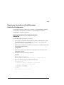
Upgrading Controller Software . . . . . . . . . . . . . . . . . . . . . . . . . . . . . . . . . . . . . . . . 3–2
Installing a New Program Card . . . . . . . . . . . . . . . . . . . . . . . . . . . . . . . . . . . . 3–3
Downloading New Software. . . . . . . . . . . . . . . . . . . . . . . . . . . . . . . . . . . . . . . 3–4
Using CLCP to Install, Delete, and List Software Patches . . . . . . . . . . . . . . . 3–8
Installing a Software Patch . . . . . . . . . . . . . . . . . . . . . . . . . . . . . . . . . . . . 3–8
Compaq HSZ80 Array Controller ACS Version 8.3 Maintenance and Service Guide
viii
Deleting a Software Patch . . . . . . . . . . . . . . . . . . . . . . . . . . . . . . . . . . . 3–10
Listing Software Patches . . . . . . . . . . . . . . . . . . . . . . . . . . . . . . . . . . . . 3–12
Upgrading Firmware on a Device . . . . . . . . . . . . . . . . . . . . . . . . . . . . . . . . . . . . . 3–14
Upgrading to a Dual-Redundant Controller Configuration . . . . . . . . . . . . . . . . . . 3–17
Installing a New Controller, Cache Module, and ECB . . . . . . . . . . . . . . . . . 3–17
Upgrading Cache Memory . . . . . . . . . . . . . . . . . . . . . . . . . . . . . . . . . . . . . . . . . . 3–22
Chapter 4
Troubleshooting
Running the Controller’s Diagnostic Test . . . . . . . . . . . . . . . . . . . . . . . . . . . . . . . . 4–2
Charging Diagnostics . . . . . . . . . . . . . . . . . . . . . . . . . . . . . . . . . . . . . . . . . . . . 4–2
Battery Hysteresis . . . . . . . . . . . . . . . . . . . . . . . . . . . . . . . . . . . . . . . . . . 4–3
Troubleshooting Checklist. . . . . . . . . . . . . . . . . . . . . . . . . . . . . . . . . . . . . . . . . . . . 4–4
Troubleshooting Table . . . . . . . . . . . . . . . . . . . . . . . . . . . . . . . . . . . . . . . . . . . . . . . 4–6
Fault-Tolerance for Write-Back Caching . . . . . . . . . . . . . . . . . . . . . . . . . . . . 4–17
Nonvolatile Memory . . . . . . . . . . . . . . . . . . . . . . . . . . . . . . . . . . . . . . . 4–17
Cache Policies Resulting from Cache Module Failures . . . . . . . . . . . . . 4–17
Significant Event Reporting. . . . . . . . . . . . . . . . . . . . . . . . . . . . . . . . . . . . . . . . . . 4–24
Events that cause controller termination . . . . . . . . . . . . . . . . . . . . . . . . . . . . 4–24
Flashing OCP Pattern Display Reporting . . . . . . . . . . . . . . . . . . . . . . . . 4–25
Solid OCP Pattern Display Reporting . . . . . . . . . . . . . . . . . . . . . . . . . . 4–27
Last Failure Reporting . . . . . . . . . . . . . . . . . . . . . . . . . . . . . . . . . . . . . . 4–33
Events that do not cause controller operation to terminate . . . . . . . . . . . . . . 4–33
Spontaneous Event Log . . . . . . . . . . . . . . . . . . . . . . . . . . . . . . . . . . . . . 4–34
CLI Event Reporting . . . . . . . . . . . . . . . . . . . . . . . . . . . . . . . . . . . . . . . 4–35
Utilities and Exercisers . . . . . . . . . . . . . . . . . . . . . . . . . . . . . . . . . . . . . . . . . . . . . 4–36
Fault Management Utility. . . . . . . . . . . . . . . . . . . . . . . . . . . . . . . . . . . . . . . . 4–36
Displaying Failure Entries . . . . . . . . . . . . . . . . . . . . . . . . . . . . . . . . . . . 4–37
Translating Event Codes . . . . . . . . . . . . . . . . . . . . . . . . . . . . . . . . . . . . 4–39
ix
Instance Codes and Last-Failure Codes . . . . . . . . . . . . . . . . . . . . . . . . . 4–40
Controlling the Display of Significant Events and Failures . . . . . . . . . . 4–40
Using VTDPY to Check for Communication Problems . . . . . . . . . . . . . . . . 4–43
Checking Controller-to-Host Communications
. . . . . . . . . . . . . . . . . . 4–45
Checking Controller-to-Device Communications . . . . . . . . . . . . . . . . . 4–47
Checking Device Type and Location . . . . . . . . . . . . . . . . . . . . . . . . 4–48
Checking Device Status and I/O Activity . . . . . . . . . . . . . . . . . . . . 4–48
Checking Device-Port Status and I/O Activity . . . . . . . . . . . . . . . . 4–50
Checking Unit Status and I/O Activity . . . . . . . . . . . . . . . . . . . . . . . . . . 4–51
Disk Inline Exerciser (DILX) . . . . . . . . . . . . . . . . . . . . . . . . . . . . . . . . . . . . . 4–55
Checking for Disk-Drive Problems . . . . . . . . . . . . . . . . . . . . . . . . . . . . 4–55
Finding a Disk Drive in the Subsystem . . . . . . . . . . . . . . . . . . . . . . 4–55
Testing the Read Capability of a Disk Drive . . . . . . . . . . . . . . . . . . 4–56
Testing the Read and Write Capabilities of a Disk Drive . . . . . . . . 4–57
DILX Error Codes . . . . . . . . . . . . . . . . . . . . . . . . . . . . . . . . . . . . . . . . . 4–60
Configuration Utility . . . . . . . . . . . . . . . . . . . . . . . . . . . . . . . . . . . . . . . . . . . 4–60
Code Load and Code Patch Utility . . . . . . . . . . . . . . . . . . . . . . . . . . . . . . . . . 4–62
Clone Utility . . . . . . . . . . . . . . . . . . . . . . . . . . . . . . . . . . . . . . . . . . . . . . . . . . 4–63
Field Replacement Utility. . . . . . . . . . . . . . . . . . . . . . . . . . . . . . . . . . . . . . . . 4–63
Change Volume Serial Number Utility. . . . . . . . . . . . . . . . . . . . . . . . . . . . . . 4–64
Device Statistics Utility . . . . . . . . . . . . . . . . . . . . . . . . . . . . . . . . . . . . . . . . . 4–64
Chapter 5
Event Reporting: Templates and Codes
Passthrough Device Reset Event Sense Data Response . . . . . . . . . . . . . . . . . . . . . 5–2
Last Failure Event Sense Data Response . . . . . . . . . . . . . . . . . . . . . . . . . . . . . 5–3
Multiple-Bus Failover Event Sense Data Response . . . . . . . . . . . . . . . . . . . . . 5–5
Failover Event Sense Data Response . . . . . . . . . . . . . . . . . . . . . . . . . . . . . . . . 5–7
Nonvolatile Parameter Memory Component Event Sense Data Response . . . 5–9
Compaq HSZ80 Array Controller ACS Version 8.3 Maintenance and Service Guide
x
Backup Battery Failure Event Sense Data Response . . . . . . . . . . . . . . . . . . . 5–11
Subsystem Built-In Self Test Failure Event Sense Data Response . . . . . . . . 5–13
Memory System Failure Event Sense Data Response . . . . . . . . . . . . . . . . . . 5–15
Device Services Non-Transfer Error Event Sense Data Response. . . . . . . . . 5–16
Disk Transfer Error Event Sense Data Response . . . . . . . . . . . . . . . . . . . . . . 5–18
Instance Codes . . . . . . . . . . . . . . . . . . . . . . . . . . . . . . . . . . . . . . . . . . . . . . . . . . . . 5–20
Instance Code Structure . . . . . . . . . . . . . . . . . . . . . . . . . . . . . . . . . . . . . . . . . 5–20
Instance Codes and FMU . . . . . . . . . . . . . . . . . . . . . . . . . . . . . . . . . . . . . . . . 5–20
NR Threshold . . . . . . . . . . . . . . . . . . . . . . . . . . . . . . . . . . . . . . . . . . . . . 5–21
Repair Action . . . . . . . . . . . . . . . . . . . . . . . . . . . . . . . . . . . . . . . . . . . . . 5–21
Event Number . . . . . . . . . . . . . . . . . . . . . . . . . . . . . . . . . . . . . . . . . . . . 5–21
Component ID . . . . . . . . . . . . . . . . . . . . . . . . . . . . . . . . . . . . . . . . . . . . 5–21
Last Failure Codes . . . . . . . . . . . . . . . . . . . . . . . . . . . . . . . . . . . . . . . . . . . . . . . . . 5–48
Last Failure Code Structure . . . . . . . . . . . . . . . . . . . . . . . . . . . . . . . . . . . . . . 5–48
Last Failure Codes and FMU . . . . . . . . . . . . . . . . . . . . . . . . . . . . . . . . . . . . . 5–48
HW . . . . . . . . . . . . . . . . . . . . . . . . . . . . . . . . . . . . . . . . . . . . . . . . . . . . . 5–49
Restart Code . . . . . . . . . . . . . . . . . . . . . . . . . . . . . . . . . . . . . . . . . . . . . . 5–49
Parameter Count . . . . . . . . . . . . . . . . . . . . . . . . . . . . . . . . . . . . . . . . . . . 5–49
Repair Action . . . . . . . . . . . . . . . . . . . . . . . . . . . . . . . . . . . . . . . . . . . . . 5–50
Error Numbers . . . . . . . . . . . . . . . . . . . . . . . . . . . . . . . . . . . . . . . . . . . . 5–50
Component IDs . . . . . . . . . . . . . . . . . . . . . . . . . . . . . . . . . . . . . . . . . . . 5–50
Recommended Repair Action Codes. . . . . . . . . . . . . . . . . . . . . . . . . . . . . . . . . . . 5–95
Component Identifier Codes . . . . . . . . . . . . . . . . . . . . . . . . . . . . . . . . . . . . . . . . 5–101
Event Threshold Codes . . . . . . . . . . . . . . . . . . . . . . . . . . . . . . . . . . . . . . . . . . . . 5–103
ASC/ASCQ Codes. . . . . . . . . . . . . . . . . . . . . . . . . . . . . . . . . . . . . . . . . . . . . . . . 5–104
xi
Chapter 6
Connectors, Switches, and LEDs
Controller Front Panel . . . . . . . . . . . . . . . . . . . . . . . . . . . . . . . . . . . . . . . . . . . . . . . 6–2
Operator Control Panel LEDs . . . . . . . . . . . . . . . . . . . . . . . . . . . . . . . . . . . . . . . . . 6–3
Power Verification and Addressing Module . . . . . . . . . . . . . . . . . . . . . . . . . . . . . . 6–4
Environmental Monitoring Unit (EMU) . . . . . . . . . . . . . . . . . . . . . . . . . . . . . . . . . 6–5
Chapter 7
Controller Specifications
Physical and Electrical Specifications for the Controller . . . . . . . . . . . . . . . . . . . . 7–2
Environmental Specifications . . . . . . . . . . . . . . . . . . . . . . . . . . . . . . . . . . . . . . . . . 7–3
Spare Part Number Cross Reference
System Components Exploded View. . . . . . . . . . . . . . . . . . . . . . . . . . . . . . . . . . . A–2
HSZ80 Array Controller . . . . . . . . . . . . . . . . . . . . . . . . . . . . . . . . . . . . . . . . . . . . A–4
Cache Module . . . . . . . . . . . . . . . . . . . . . . . . . . . . . . . . . . . . . . . . . . . . . . . . . . . . A–6
Environmental Monitoring Unit (EMU) . . . . . . . . . . . . . . . . . . . . . . . . . . . . . . . . A–7
Glossary
Index
Compaq HSZ80 Array Controller ACS Version 8.3 Maintenance and Service Guide
xiii
Figures
The HSZ80 Subsystem . . . . . . . . . . . . . . . . . . . . . . . . . . . . . . . . . . . . . . . . . . . . . . 1–2
HSZ80 Array Controller . . . . . . . . . . . . . . . . . . . . . . . . . . . . . . . . . . . . . . . . . . . . . 1–4
Cache Module . . . . . . . . . . . . . . . . . . . . . . . . . . . . . . . . . . . . . . . . . . . . . . . . . . . . . 1–6
EMU . . . . . . . . . . . . . . . . . . . . . . . . . . . . . . . . . . . . . . . . . . . . . . . . . . . . . . . . . . . . 1–7
PC/Terminal to Maintenance Port Connection . . . . . . . . . . . . . . . . . . . . . . . . . . . . 2–3
ECB SBB Battery Disable Switch Location . . . . . . . . . . . . . . . . . . . . . . . . . . . . . . 2–6
Single-Controller Configuration . . . . . . . . . . . . . . . . . . . . . . . . . . . . . . . . . . . . . . . 2–8
Dual-Redundant Controller Configuration . . . . . . . . . . . . . . . . . . . . . . . . . . . . . . 2–16
ECB SBB Configuration . . . . . . . . . . . . . . . . . . . . . . . . . . . . . . . . . . . . . . . . . . . . 2–38
I/O Module Locations in a BA370 Enclosure . . . . . . . . . . . . . . . . . . . . . . . . . . . 2–46
I/O Module Locations . . . . . . . . . . . . . . . . . . . . . . . . . . . . . . . . . . . . . . . . . . . . . . 2–47
Cache-Module Memory Configurations . . . . . . . . . . . . . . . . . . . . . . . . . . . . . . . . 2–52
DIMM Components . . . . . . . . . . . . . . . . . . . . . . . . . . . . . . . . . . . . . . . . . . . . . . . 2–54
PCMCIA Card . . . . . . . . . . . . . . . . . . . . . . . . . . . . . . . . . . . . . . . . . . . . . . . . . . . 2–55
PCMCIA Card . . . . . . . . . . . . . . . . . . . . . . . . . . . . . . . . . . . . . . . . . . . . . . . . . . . . 3–2
Location of Write-Protection Switch . . . . . . . . . . . . . . . . . . . . . . . . . . . . . . . . . . . 3–5
Upgrading Device Firmware . . . . . . . . . . . . . . . . . . . . . . . . . . . . . . . . . . . . . . . . 3–14
Cache-Module Memory Configurations . . . . . . . . . . . . . . . . . . . . . . . . . . . . . . . . 3–22
DIMM Components . . . . . . . . . . . . . . . . . . . . . . . . . . . . . . . . . . . . . . . . . . . . . . . 3–24
Xfer Rate Region of the Default Display . . . . . . . . . . . . . . . . . . . . . . . . . . . . . . . 4–45
Regions on the Device Display . . . . . . . . . . . . . . . . . . . . . . . . . . . . . . . . . . . . . . . 4–47
Unit Status on the Cache Display . . . . . . . . . . . . . . . . . . . . . . . . . . . . . . . . . . . . . 4–52
Passthrough Device Reset Event Sense Data Response Format . . . . . . . . . . . . . . . 5–2
Template 01 - Last Failure Event Sense Data Response Format . . . . . . . . . . . . . . 5–4
Template 04 - Multiple-Bus Failover Event Sense Data Response Format . . . . . . 5–6
Template 05 - Failover Event Sense Data Response Format . . . . . . . . . . . . . . . . . 5–8
Compaq HSZ80 Array Controller ACS Version 8.3 Maintenance and Service Guide
xiv
Template 11 - Nonvolatile Parameter Memory Component Event Sense
Data Response Format . . . . . . . . . . . . . . . . . . . . . . . . . . . . . . . . . . . . . . . . . . . . 5–10
Template 12 - Backup Battery Failure Event Sense Data Response Format . . . . 5–12
Template 13 - Subsystem Built-In Self Test Failure Event Sense Data
Response Format . . . . . . . . . . . . . . . . . . . . . . . . . . . . . . . . . . . . . . . . . . . . . . . . 5–14
Template 14 - Memory System Failure Event Sense Data Response Format . . . 5–15
Template 41 - Device Services Non-Transfer Error Event Sense Data
Response Format . . . . . . . . . . . . . . . . . . . . . . . . . . . . . . . . . . . . . . . . . . . . . . . . 5–17
Template 51 - Disk Transfer Error Event Sense Data Response Format . . . . . . . 5–19
Structure of an Instance Code . . . . . . . . . . . . . . . . . . . . . . . . . . . . . . . . . . . . . . . . 5–20
Instance Code Format . . . . . . . . . . . . . . . . . . . . . . . . . . . . . . . . . . . . . . . . . . . . . . 5–20
Structure of a Last Failure Code . . . . . . . . . . . . . . . . . . . . . . . . . . . . . . . . . . . . . . 5–48
Last Failure Code Format . . . . . . . . . . . . . . . . . . . . . . . . . . . . . . . . . . . . . . . . . . . 5–48
Controller Front Panel Connectors, Switches, and LEDS . . . . . . . . . . . . . . . . . . . 6–2
Operator Control Panel Switches and LEDs . . . . . . . . . . . . . . . . . . . . . . . . . . . . . 6–3
PVA Module Connectors and Switches . . . . . . . . . . . . . . . . . . . . . . . . . . . . . . . . . 6–4
EMU Connectors, Switches, and LEDs . . . . . . . . . . . . . . . . . . . . . . . . . . . . . . . . . 6–5
The HSZ80 Subsystem . . . . . . . . . . . . . . . . . . . . . . . . . . . . . . . . . . . . . . . . . . . . . .A–2
HSZ80 Array Controller . . . . . . . . . . . . . . . . . . . . . . . . . . . . . . . . . . . . . . . . . . . . .A–4
Cache Module . . . . . . . . . . . . . . . . . . . . . . . . . . . . . . . . . . . . . . . . . . . . . . . . . . . . .A–6
EMU . . . . . . . . . . . . . . . . . . . . . . . . . . . . . . . . . . . . . . . . . . . . . . . . . . . . . . . . . . . .A–7
Compaq HSZ80 Array Controller ACS Version 8.3 Maintenance and Service Guide
xv
Tables
The HSZ80 Subsystem . . . . . . . . . . . . . . . . . . . . . . . . . . . . . . . . . . . . . . . . . . . . . 1–3
HSZ80 Fibre Channel Array Controller . . . . . . . . . . . . . . . . . . . . . . . . . . . . . . . . 1–5
Cache Module . . . . . . . . . . . . . . . . . . . . . . . . . . . . . . . . . . . . . . . . . . . . . . . . . . . . . 1–6
EMU . . . . . . . . . . . . . . . . . . . . . . . . . . . . . . . . . . . . . . . . . . . . . . . . . . . . . . . . . . . . 1–7
Description of PC/Terminal to Maintenance Port Connection . . . . . . . . . . . . . . . . 2–4
Description of ECB SBB Battery Disable Switch . . . . . . . . . . . . . . . . . . . . . . . . . 2–6
Description of Single-Controller Configuration . . . . . . . . . . . . . . . . . . . . . . . . . . . 2–8
Description of Dual-Redundant-Controller Configuration . . . . . . . . . . . . . . . . . . 2–16
ECB SBB Configuration . . . . . . . . . . . . . . . . . . . . . . . . . . . . . . . . . . . . . . . . . . . . 2–38
Description of I/O Modules in a BA370 Enclosure . . . . . . . . . . . . . . . . . . . . . . . 2–46
Cache Module Memory Configurations . . . . . . . . . . . . . . . . . . . . . . . . . . . . . . . . 2–52
DIMM Components . . . . . . . . . . . . . . . . . . . . . . . . . . . . . . . . . . . . . . . . . . . . . . . 2–54
PCMCIA Card . . . . . . . . . . . . . . . . . . . . . . . . . . . . . . . . . . . . . . . . . . . . . . . . . . . 2–55
PCMCIA Card . . . . . . . . . . . . . . . . . . . . . . . . . . . . . . . . . . . . . . . . . . . . . . . . . . . . 3–2
Cache Module Memory Configurations . . . . . . . . . . . . . . . . . . . . . . . . . . . . . . . . 3–22
DIMM Components . . . . . . . . . . . . . . . . . . . . . . . . . . . . . . . . . . . . . . . . . . . . . . . 3–24
Troubleshooting Table . . . . . . . . . . . . . . . . . . . . . . . . . . . . . . . . . . . . . . . . . . . . . . 4–6
Cache Policies and Cache Module Status . . . . . . . . . . . . . . . . . . . . . . . . . . . . . . 4–18
Resulting Cache Policies and ECB Status
. . . . . . . . . . . . . . . . . . . . . . . . . . . . . 4–20
Flashing OCP Patterns . . . . . . . . . . . . . . . . . . . . . . . . . . . . . . . . . . . . . . . . . . . . . 4–25
Solid OCP Patterns . . . . . . . . . . . . . . . . . . . . . . . . . . . . . . . . . . . . . . . . . . . . . . . 4–27
Event-Code Types . . . . . . . . . . . . . . . . . . . . . . . . . . . . . . . . . . . . . . . . . . . . . . . . . 4–39
FMU SET Commands . . . . . . . . . . . . . . . . . . . . . . . . . . . . . . . . . . . . . . . . . . . . . 4–41
VTDPY Key Sequences and Commands . . . . . . . . . . . . . . . . . . . . . . . . . . . . . . . 4–44
Xfer Rate Columns . . . . . . . . . . . . . . . . . . . . . . . . . . . . . . . . . . . . . . . . . . . . . . . 4–46
Device Map Columns . . . . . . . . . . . . . . . . . . . . . . . . . . . . . . . . . . . . . . . . . . . . . 4–48
Device Status Columns . . . . . . . . . . . . . . . . . . . . . . . . . . . . . . . . . . . . . . . . . . . . 4–49
Compaq HSZ80 Array Controller ACS Version 8.3 Maintenance and Service Guide
xvi
Device-Port Status Columns . . . . . . . . . . . . . . . . . . . . . . . . . . . . . . . . . . . . . . . . 4–51
Unit Status Columns . . . . . . . . . . . . . . . . . . . . . . . . . . . . . . . . . . . . . . . . . . . . . . 4–53
DILX Control Sequences . . . . . . . . . . . . . . . . . . . . . . . . . . . . . . . . . . . . . . . . . . . 4–56
Data Patterns for Phase 1: Write Test . . . . . . . . . . . . . . . . . . . . . . . . . . . . . . . . . . 4–58
DILX Error Codes . . . . . . . . . . . . . . . . . . . . . . . . . . . . . . . . . . . . . . . . . . . . . . . . 4–60
HSUTIL Messages and Inquiries . . . . . . . . . . . . . . . . . . . . . . . . . . . . . . . . . . . . . 4–61
Instance Codes . . . . . . . . . . . . . . . . . . . . . . . . . . . . . . . . . . . . . . . . . . . . . . . . . . . 5–22
Controller Restart Codes . . . . . . . . . . . . . . . . . . . . . . . . . . . . . . . . . . . . . . . . . . . . 5–49
Last Failure Codes . . . . . . . . . . . . . . . . . . . . . . . . . . . . . . . . . . . . . . . . . . . . . . . . 5–50
Recommended Repair Action Codes . . . . . . . . . . . . . . . . . . . . . . . . . . . . . . . . . . 5–95
Component Identifier Codes . . . . . . . . . . . . . . . . . . . . . . . . . . . . . . . . . . . . . . . 5–101
Event Notification/Recovery Threshold Classifications . . . . . . . . . . . . . . . . . . . 5–103
ASC and ASCQ Codes . . . . . . . . . . . . . . . . . . . . . . . . . . . . . . . . . . . . . . . . . . . 5–104
Controller Front Panel Connectors, Switches, and LEDs . . . . . . . . . . . . . . . . . . . . 6–2
Operator Control Panel Switches and LEDs . . . . . . . . . . . . . . . . . . . . . . . . . . . . . 6–3
PVA Connectors and Switches . . . . . . . . . . . . . . . . . . . . . . . . . . . . . . . . . . . . . . . . 6–4
EMU Connectors, Switches, and LEDs . . . . . . . . . . . . . . . . . . . . . . . . . . . . . . . . . 6–5
Controller Specifications . . . . . . . . . . . . . . . . . . . . . . . . . . . . . . . . . . . . . . . . . . . . 7–2
Optimum Operating Environmental Specifications . . . . . . . . . . . . . . . . . . . . . . . . 7–3
Maximum Operating Environmental Specifications . . . . . . . . . . . . . . . . . . . . . . . 7–4
Maximum Nonoperating Environmental Specifications . . . . . . . . . . . . . . . . . . . . 7–4
The HSZ80 Subsystem . . . . . . . . . . . . . . . . . . . . . . . . . . . . . . . . . . . . . . . . . . . . .A–3
HSZ80 Array Controller . . . . . . . . . . . . . . . . . . . . . . . . . . . . . . . . . . . . . . . . . . . . .A–5
Cache Module . . . . . . . . . . . . . . . . . . . . . . . . . . . . . . . . . . . . . . . . . . . . . . . . . . . . .A–6
EMU . . . . . . . . . . . . . . . . . . . . . . . . . . . . . . . . . . . . . . . . . . . . . . . . . . . . . . . . . . . .A–7
Compaq HSZ80 Array Controller ACS Version 8.3 Maintenance and Service Guide
xvii
About this Guide
This book describes the features of the HSZ80 array controller and configuration
procedures for the controller and storagesets running Array Controller Software
(ACS) Version 8.3Z.
This book does not contain information about the operating environments to which
the controller may be connected, nor does it contain detailed information about
subsystem enclosures or their components. See the documentation that accompanied
these peripherals for information about them.
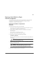
Getting Help
If you have a problem and have exhausted the information in this guide, you can get
further information and other help in the following locations.
Compaq Website
The COMPAQ Website has information on this product as well as the latest drivers
and Flash ROM images. You can access the COMPAQ website by logging on to the
Internet at http://www.compaq.com.
Telephone Numbers
For the name of your nearest COMPAQ Authorized Reseller:
In the United States, call 1-800-345-1518.
In Canada, call 1-800-263-5868.
For Compaq technical support:
In the United States and Canada, call 1-800-386-2172.
For COMPAQ technical support phone numbers outside the United States and
Canada, visit the COMPAQ Website at: http://www.compaq.com.
Compaq HSZ80 Array Controller ACS Version 8.3 Maintenance and Service Guide
xviii
About this Guide
Precautions
Follow these precautions when carrying out the procedures in this book.
Electrostatic Discharge Precautions
Static electricity collects on all nonconducting material, such as paper, cloth, and
plastic. An electrostatic discharge (ESD) can easily damage a controller or other
subsystem component even though you may not see or feel the discharge. Follow
these precautions whenever you’re servicing a subsystem or one of its components:
■
Always use an ESD wrist strap when servicing the controller or other
components in the subsystem. Make sure that the strap contacts bare skin, fits
snugly, and that its grounding lead is attached to a bus that is a verified earth
ground.
■
Before touching any circuit board or component, always touch a verifiable earth
ground to discharge any static electricity that may be present in your clothing.
■
Always keep circuit boards and components away from nonconducting material.
■
Always keep clothing away from circuit boards and components.
■
Always use antistatic bags and grounding mats for storing circuit boards or
components during replacement procedures.
■
Always keep the ESD cover over the program card when the card is in the
controller. If you remove the card, put it in its original carrying case. Never touch
the contacts or twist or bend the card while you’re handling it.
■
Never touch the connector pins of a cable when it is attached to a component or
host.
Component Precaution
System components referenced in this manual comply to regulatory standards
documented herein. Use of other components in their place may violate country
standards, negate regulatory compliance, or invalidate the warranty on your product.
xix
Maintenance Port Precautions
The maintenance port generates, uses, and radiates radio-frequency energy through
cables that are connected to it. This energy may interfere with radio and television
reception. Do not leave a cable connected to this port when you’re not communicating
with the controller.
Compaq HSZ80 Array Controller ACS Version 8.3 Maintenance and Service Guide
xx
About this Guide
Conventions
This book uses the following typographical conventions and special notices to help
you find what you’re looking for.
Typographical Conventions
Convention
ALLCAPS
Meaning
Command syntax that must be entered exactly as shown
and for commands discussed within text, for example:
SET FAILOVER COPY=OTHER_CONTROLLER
“Use the SHOW SPARESET command to show the contents of
the spareset.”
Monospaced
Sans serif italic
Screen display.
Command variable or numeric value that you supply, for
example: SHOW RAIDset-name or
set this_controller id=(n,n,n,n,)
italic
Reference to other books or publications, for example:
“See the HSG80 Array Controller ACS V8.2 Release Notes
for details.”
.
.
.
Indicates that a portion of an example or figure has been
omitted.
“this controller”
The controller serving your current CLI session through a
local or remote terminal.
“other controller”
The controller in a dual-redundant pair that’s connected
to the controller serving your current CLI session.
xxi
Special Notices
This book doesn’t contain detailed descriptions of standard safety procedures.
However, it does contain warnings for procedures that could cause personal injury and
cautions for procedures that could damage the controller or its related components.
Look for these symbols when you’re carrying out the procedures in this book:
WARNING: A warning indicates the presence of a hazard that can cause
personal injury if you do not observe the precautions in the text.
CAUTION: A caution indicates the presence of a hazard that might damage hardware, corrupt software, or cause a loss of data.
IMPORTANT: An important note is a type of note that provides information
essential to the completion of a task. Users can disregard information in a note
and still complete a task, but they should not disregard an important note.
NOTE: A note provides additional information that’s related to the completion of an
instruction or procedure.
Compaq HSZ80 Array Controller ACS Version 8.3 Maintenance and Service Guide
xxii
About this Guide
Required Tools
You will need the following tools to service the controller, cache module, external
cache battery (ECB), the Power Verification and Addressing (PVA) module, the
Gigabit Link Module (GLM), and the I/O module:
■
A flathead screwdriver for loosening and tightening the I/O module retaining
screws.
■
An antistatic wrist strap.
■
An antistatic mat on which to place modules during servicing.
■
A Storage Building Block (SBB) Extractor for removing StorageWorks building
blocks. This tool is not required, but it will enable you to perform more
efficiently.
xxiii
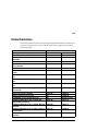
Related Publications
The following table lists some of the Compaq StorageWorks documents related to the
use of the controller, cache module, external cache battery, graphical user interface,
and the subsystem.
Document Title
BA370 Enclosure Rack Template (Compaq 42U Rack)
Command Console Version 2.1 HSZ80 User’s Guide
Disaster Tolerant Solutions Getting Started Guide for
DIGITAL UNIX
Disaster Tolerant Solutions User’s Guide for DIGITAL UNIX
External Cache Battery Shelf Installation Card
(Compaq 42U Rack)
Hardware Configuration Poster for HSZ80
HSZ80 Array Controller ACS V8.3 for DIGITAL UNIX
CD-ROM
HSZ80 Array Controller ACS V8.3 for DIGITIAL UNIX Release
Notes
HSZ80 Array Controller ACS V8.3 for IBM-AIX Release
Notes
HSZ80 Array Controller ACS V8.3 for OpenVMS Release
Notes
HSZ80 Array Controller ACS V8.3 Configuration and CLI
Reference Guide
HSZ80 Array Controller Illustrated Parts Map
Installation Card (Compaq 42U Rack)
Installing a Ferrite Bead on a Host Bus
The RAIDBOOK—A Source for RAID Technology
RA8000/ESA12000 HSZ80 ACS V8.3 for DIGITAL UNIX
Installation Reference Manual
RA8000/ESA12000 HSZ80 ACS V8.3 for DIGITAL UNIX Quick
Setup Guide
RA8000/ESA12000 HSZ80 ACS V8.3 for IBM-AIX Installation
Reference Manual
RA8000/ESA12000 HSZ80 ACS V8.3 for IBM-AIX Quick
Setup Guide
355224-001
388725-001
N/A
Part Number
EK-RKTMP-TP
AA-RF9TA-TE
AA-RC3CA-TE
N/A
355222-001
EK-SWXDT-UG
EK-HSECB-IC
388724-001
N/A
EK-HSZ80-CP
AG-RFA0A-BE
388713-001
AA-RF9YA-TE
388711-001
AA-RFALA-TE
388712-001
AA-RFAEA-TE
388222-001
EK-HSZ80-RG
388220-001
355210-001
N/A
N/A
388701-001
EK-HSZ80-MP
EK-H80RM-IC
EK-SWXES-IG
RAID Advisory Board
AA-RF9ZA-TE
388700-001
AA-RF9XA-TE
388710-001
AA-RFAMA-TE
388709-001
AA-RFAKA-TE
Compaq HSZ80 Array Controller ACS Version 8.3 Maintenance and Service Guide
xxiv
About this Guide
Document Title
RA8000/ESA12000 HSZ80 ACS V8.3 for OpenVMS
Installation Reference Manual
RA8000/ESA12000 HSZ80 ACS V8.3 for OpenVMS Quick
Setup Guide
RA8000/ESA12000 Storage Subsystem User’s Guide
Rail Mounting Installation Card (Compaq 42U Rack)
Ultra SCSI RAID Enclosure (DS-BA370 Series) User’s Guide
Warranty Terms and Conditions
Revision History
This is a new document.
388733-001
Part Number
AA-RFAFA-TE
388732-001
AA-RFADA-TE
387404-001
355223-001
387403-001
N/A
EK-SMCPR-UG
EK-H8RMB-IC
EK-BA370-UG
EK-HSXSW-WC
1–1
Chapter 1
General Description
This chapter provides the illustrated parts breakdown and a spare list for the HSZ80
array controller subsystem. See for the names of referenced spare parts.
Compaq HSZ80 Array Controller ACS Version 8.3 Maintenance and Service Guide
1–2
General Description
System Components
Exploded View
1
16
2
15
13
14
3
12 2x
4
11
10
9 2x
5
8 2x
6
7
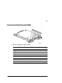
CXO6742A
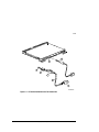
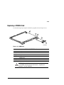
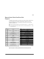
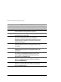
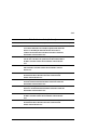
Figure 1–1 The HSZ80 Subsystem
1–3
Table 1–1 The HSZ80 Subsystem
Item
Description
Part Number
1
BA370 rack-mountable enclosure
401914-001
2
Cooling fan, blue
Cooling fan, gray
400293-001
402602-001
3
Power cable kit, white
401915-001
4
I/O module, blue
I/O module, gray
400294-001
401911-001
5
SCSI hub, 3 port
401926-001
6
SCSI hub, 5 port
401927-001
7
SCSI hub, 9 port, upgrade
NOTE: A complete 9-port SCSI hub requires a 5-port
SCSI hub
401929-001
and
401927-001
8
Cache module
400295-001
9
HSZ80 controller
103539-001
10
PVA module
400299-001
11
EMU
400286-001
12
AC input module
400287-001
13
180-watt power supply
400288-001
14
Disk drive, 4 GB, 7200
Disk drive, 9 GB, 7200
Disk drive, 18 GB, 7200
Disk drive, 9 GB, 10K
Disk drive, 18 GB, 10K
402153-001
400289-001
400290-001
402154-001
402229-001
15
Power cable, black
401915-001
16
ECB, dual (shown)
ECB, single (not shown)
400291-001
400292-001
Compaq HSZ80 Array Controller ACS Version 8.3 Maintenance and Service Guide
1–4
General Description
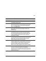
HSZ80 Array Controller
1
1
2
3
4
5
6
2
3
6
4
5
CXO6703A
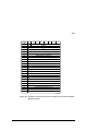
Figure 1–2 HSZ80 Array Controller
1–5
Table 1–2 HSZ80 Fibre Channel Array Controller
Item
Description
Part No.
1
Program card
103474-001
2
Trilink connectors
401948-001
3
Host bus cable, 1.5 meter
Host bus cable, 2 meter
Host bus cable, 10 meter
Host bus cable, 15 meter
Host bus cable, 20 meterr
401941-001
401940-001
401942-001
401943-001
401944-001
4
Terminator
401947-001
5
Jumper cable
401939-001
6
Maintenance port cable
402605-001
Compaq HSZ80 Array Controller ACS Version 8.3 Maintenance and Service Guide
1–6
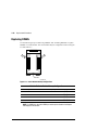
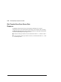
General Description
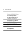
Cache Module
1
~
2
CXO6570A
Figure 1–3 Cache Module
Table 1–3 Cache Module
Item
1
2
Description
Part No.
DIMM, 32 MB
400296-001
DIMM, 128 MB
400297-001
ECB Y cable for the BA370 Enclosure
400298-001
ECB Y cable for the Data Center Cabinet
401913-001
1–7
Environmental Monitoring Unit (EMU)
1
CXO6604A
Figure 1–4 EMU
Table 1–4 EMU
Item
1
Description
EMU communication cable, 4 meter
Part No.
401949-001
Compaq HSZ80 Array Controller ACS Version 8.3 Maintenance and Service Guide
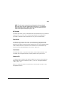
2–1
Chapter 2
Replacement Procedures
This chapter describes the procedures for replacing the controller, cache module,
external cache battery (ECB), power verification and addressing (PVA) module, I/O
module, environmental monitoring unit (EMU), DIMMs, PCMCIA card, and a failed
storageset member. Additionally, there are procedures for shutting down and
restarting the subsystem.
See the enclosure documentation for information about the power supplies, cooling
fans, and cables.
Required Tools
You will need the following tools to service the controller, cache module, external
cache battery (ECB), the Power Verification and Addressing (PVA) module, and the
I/O module:
■
A flathead screwdriver for loosening and tightening the I/O module retaining
screws.
■
An antistatic wrist strap.
■
An antistatic mat on which to place modules during servicing.
■
A Storage Building Block (SBB) Extractor for removing StorageWorks building
blocks. This tool is not required, but it will enable you to work more efficiently.
Electrostatic Discharge
Electrostatic discharge (ESD) is a common problem and may cause data loss, system
down time, and other problems. The most common source of static electricity is the
movement of people in contact with carpets and clothing. Low humidity also
increases the amount of static electricity. You must discharge all static electricity
prior to touching electronic equipment. Follow the precautions in Electrostatic
Discharge Precautions given in the Preface whenever you are replacing any
component.
Compaq HSZ80 Array Controller ACS Version 8.3 Maintenance and Service Guide
2–2
Replacement Procedures
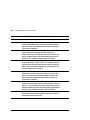
Preparation Procedures
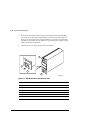
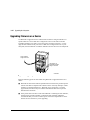
Establishing a Local Connection to the
Controller
You can communicate with a controller locally or remotely. Use a local connection to
configure the controller for the first time. Use a remote connection to your host
system for all subsequent configuration tasks. See the Quick Setup Guide that came
with your platform kit for details.
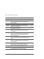
The maintenance port provides a convenient way to connect a PC or terminal to the
controller so that you can troubleshoot and configure the controller. This port accepts
a standard RS-232 jack from any EIA-423 compatible terminal or a PC with a
terminal-emulation program. The maintenance port supports serial communications
with default values of 9600 baud using 8 data bits, 1 stop bit, and no parity.
NOTE: There are two maintenance port cables shown in Figure 2–1. One has a 9pin connector molded onto its end for a PC connection. An optional cable is
available for a terminal connection.
Follow these steps to establish a local connection for setting the controller’s initial
configuration:
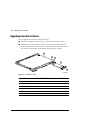
1.
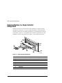
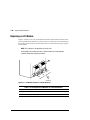
Turn off the PC or terminal, and connect it to the controller, as shown in Figure
2–1.
a.
For a PC connection, plug one end of the maintenance port cable into the terminal; plug the other end into the controller’s maintenance port.
b.
For a terminal connection, refer to Figure 2–1 on page 2–3 for cabling information.
2.
Turn on the PC or terminal.
3.
Configure the terminal emulation software for 9600 baud, 8 data bits, 1 stop bit,
and no parity.
2–3
1
2
3
4
5
6
1
2
3
4
5
6
7
CXO6584A
Figure 2–1. PC/Terminal to Maintenance Port Connection
Compaq HSZ80 Array Controller ACS Version 8.3 Maintenance and Service Guide
2–4
Replacement Procedures
Table 2–1 Description of PC/Terminal to Maintenance Port Connection
Location
Description
➀
Maintenance port cable for a PC
➁
Maintenance Port
Optional maintenance port cable for a terminal connection
➂
BC16E-xx cable assembly
➃
Ferrite bead
➄
RJ-11 adapter
➅
RJ-11 extension cable
➆
PC serial port adapter, 9 pin D-sub to 25 pin D-sub
CAUTION: The cables connecting the controller and the PC (or terminal)
may cause radio and television interference. Only connect a PC or
terminal to the controller via the maintenance port when you need to
communicate with the controller.
4.
Press the Enter or Return key. The CLI prompt appears, indicating that you
established a local connection with the controller.
5.
Optional: to increase the data transfer rate to 19200 baud:
NOTE: If you are replacing a controller, do not increase the data transfer rate to
19200 baud. A new controller is set to 9600 baud (default).
a.
Set the controller to 19200 baud with one of the following commands:
SET THIS_CONTROLLER TERMINAL SPEED=19200
SET OTHER_CONTROLLER TERMINAL SPEED=19200
b.
Configure the PC or terminal for 19200 baud.
When you are entering CLI commands in a dual-redundant controller configuration,
remember that the conroller to which you’re connected is “this controller” and the
remaining controller is the “other controller.”
2–5
Shutting Down the Subsystem
Use the following steps to shut down a subsystem:
1.
From a host console, stop all host activity and dismount the logical units in the
subsystem.
2.
Connect a PC or terminal to the maintenance port of one of the controllers in
your subsystem.
3.
Shut down the controllers. In single controller configurations, you only need to
shut down “this controller.” In dual-redundant controller configurations, shut
down the “other controller” first, then shut down “this controller” with the
following commands:
SHUTDOWN OTHER_CONTROLLER
SHUTDOWN THIS_CONTROLLER
When the controllers shut down, their reset buttons and their first three LEDs are
lit continuously. This may take several minutes, depending on the amount of data
that needs to be flushed from the cache modules.
4.
Turn off the power to the subsystem.
CAUTION: If you are shutting down the controller for longer than one
day, perform the steps in the next section, “Disabling the External Cache
Batteries,” to prevent the write-back cache batteries from discharging.
Disabling the External Cache Batteries
Use the following steps to disable the External Cache Batteries (ECBs):
NOTE: The ECB SBB may contain one or two batteries, depending on the
configuration.
Compaq HSZ80 Array Controller ACS Version 8.3 Maintenance and Service Guide
2–6
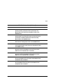
Replacement Procedures
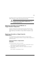
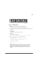
1.
Press the battery-disable switch located on each battery within the ECB SBB.
The switch is the small button labeled SHUT OFF next to the status LED (see
Figure 2–2). Press each switch for approximately five seconds. The status LED
will flash once and then shut off. Make sure you perform this procedure on both
ECB 1 and ECB 2, if appropriate.
2.
The batteries are no longer powering the cache module.
1
3
4
5
2
CXO6164B
Figure 2–2. ECB SBB Battery Disable Switch Location
Table 2–2 Description of ECB SBB Battery Disable Switch
Location
Description
➀
External Cache Battery 1
➁
External Cache Battery 2
➂
Power connector
➃
Status LED
➄
Battery disable switch
2–7
NOTE: To return to normal operation, apply power to the storage subsystem. The
cache battery will be enabled when the subsystem is powered on.
Restarting the Subsystem
Use the following steps to restart a subsystem:
1.
Plug in the subsystem’s power cord, if it is not already plugged in.
2.
Turn on the subsystem. The controllers automatically restart and the ECBs
automatically re-enable themselves to provide backup power to the cache
modules.
Compaq HSZ80 Array Controller ACS Version 8.3 Maintenance and Service Guide
2–8
Replacement Procedures
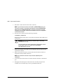
Replacing Modules in a Single-Controller
Configuration
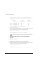
Follow the instructions in this section to replace modules in a single-controller
configuration (see Figure 2–3). If you’re replacing modules in a dual-redundant
controller configuration, see “Replacing Modules in a Dual-Redundant Controller
Configuration,” page 2–16. To upgrade a single controller configuration to a dual
redundant controller configuration, see Chapter 3, “Upgrading the Subsystem.”
1
2
3
4
5
CXO6290B
Figure 2–3. Single-Controller Configuration
Table 2–3 Description of Single-Controller Configuration
Location
Description
➀
EMU
➁
Controller
➂
Trilink connector and cables
➃
Cache Module
➄
PVA Module
2–9
The following sections cover procedures for replacing both the controller and cache
module, replacing the controller, and replacing the cache module.
CAUTION: In a single-controller configuration, you must shut down the
subsystem before removing or replacing any modules. If you remove the
controller or any other module without first shutting down the
subsystem, data loss may occur.
Replacing a Controller and Cache Module in a
Single-Controller Configuration
If both the controller and cache module need to be replaced, follow the steps in
“Replacing a Controller in a Single-Controller Configuration,” page 2–9, and the
steps in “Replacing a Cache Module in a Single-Controller Configuration,” page
2–13.
Replacing a Controller in a Single-Controller
Configuration
Use the following steps in “Removing the Controller in a Single-Controller
Configuration” and “Installing the Controller in a Single-Controller Configuration” to
replace the controller.
Removing the Controller in a Single-Controller
Configuration
Use the following steps to remove the controller:
1.
From the host console, dismount the logical units in the subsystem. If you are
using a Windows NT platform, shut down the server.
2.
If the controller is operating, connect a PC or terminal to the controller’s
maintenance port.
If the controller is not operating, go to step 5.
Compaq HSZ80 Array Controller ACS Version 8.3 Maintenance and Service Guide
2–10
Replacement Procedures
3.
Run FMU to obtain the last failure codes, if desired.
NOTE: If you initialized a container with the SAVE_ CONFIGURATION switch, you
can save this controller’s current device configuration using the CONFIGURATION
SAVE command. If CONFIGURATION SAVE is not used, you will have to manually
configure the new controller as described in HSZ80 ACS Version 8.3 Configuration
and CLI Reference Guide.
4.
Shut down the controller with the following command:
SHUTDOWN THIS_CONTROLLER
When the controller shuts down, its reset button and the first three LEDs are lit
continuously.
CAUTION: ESD can easily damage a controller. Wear a snug-fitting,
grounded ESD wrist strap.
The cache module may contain unwritten data if the controller crashed
and you weren’t able to shut it down with the SHUTDOWN
THIS_CONTROLLER command.
5.
Remove the program card’s ESD cover and program card. Save them for the
replacement controller.
6.
Remove the trilink connectors, but don’t disconnect the host bus cables (or
terminators) from the trilink connectors.
NOTE: One or two trilink connectors may be attached, depending on the
configuration.
7.
If connected, disconnect the PC or terminal from the controller’s maintenance
port.
8.
Disengage both retaining levers and remove the controller, then place the
controller into an antistatic bag or onto a grounded antistatic mat.
2–11
Installing the Controller in a Single-Controller
Configuration
Use the following steps to install the controller:
CAUTION: ESD can easily damage a controller. Wear a snug-fitting,
grounded ESD wrist strap.
Make sure you align the controller in the appropriate guide rails. If you
do not align the module correctly, damage to the backplane can occur.
1.
Insert the new controller into its slot, and engage its retaining levers.
2.
Connect the trilink connectors to the new controller.
NOTE: One or two trilink connectors may be attached, depending on the
configuration.
3.
Connect a PC or terminal to the controller’s maintenance port.
4.
Hold the reset button while inserting the program card into the new controller.
Release the reset button and replace the ESD cover.
5.
When the CLI prompt reappears, display details about the controller you
configured. Use the following command:
SHOW THIS_CONTROLLER FULL
See the SHOW THIS_CONTROLLER FULL in HSZ80 ACS Version 8.3 Configuration and CLI Reference Guide for more information about using this command.
6.
See HSZ80 ACS Version 8.3 Configuration and CLI Reference Guide to configure
the controller.
NOTE: If the controller you’re installing was previously used in another subsystem,
it will need to be purged of the controller’s old configuration (see HSZ80 ACS
Version 8.3 Configuration and CLI Reference Guide).
7.
To restore a configuration saved with the SAVE_CONFIGURATION switch,
hold button 6 while pressing and releasing the reset button.
Compaq HSZ80 Array Controller ACS Version 8.3 Maintenance and Service Guide
2–12
Replacement Procedures
8.
Using CLCP, install any patches that you had installed on the previous controller
(see Chapter 3, “Upgrading the Subsystem.”)
9.
Mount the logical units on the host. If you are using a Windows NT platform,
restart the server.
10. Set the subsystem date and time with the following command:
SET THIS_CONTROLLER TIME=dd-mmm-yyyy:hh:mm:ss
11. Disconnect the PC or terminal from the controller’s maintenance port.
2–13
Replacing a Cache Module in a SingleController Configuration
Use the following steps in “Removing the Cache Module in a Single-Controller
Configuration” and “Installing the Cache Module in a Single-Controller
Configuration” to replace the cache module.
Removing the Cache Module in a Single-Controller
Configuration
Use the following steps to remove the cache module:
1.
From the host console, dismount the logical units in the subsystem. If you are
using a Windows NT platform, shut down the server.
2.
If the controller is operating, connect a PC or terminal to the controller’s
maintenance port.
If the controller is not operating, go to step 5.
3.
Run FMU to obtain the last failure codes, if desired.
4.
Shut down the controller with the following command:
SHUTDOWN THIS_CONTROLLER
When the controller shuts down, its reset button and the first three LEDs are lit
continuously.
CAUTION: ESD can easily damage a cache module or a DIMM. Wear a
snug-fitting, grounded ESD wrist strap.
5.
Disable the ECB by pressing the battery disable switch until the status light stops
blinking—about five seconds.
CAUTION: The ECB must be disabled—the status light is not lit and is
not blinking—before disconnecting the ECB cable from the cache
module. Failure to disable the ECB could damage the cache module.
6.
Disconnect the ECB cable from the cache module.
Compaq HSZ80 Array Controller ACS Version 8.3 Maintenance and Service Guide
2–14
Replacement Procedures
7.
Disengage both retaining levers, remove the cache module, and place the cache
module into an antistatic bag or onto a grounded antistatic mat.
NOTE: Remove the DIMMs from the cache module. They will be installed in the
replacement cache module.
8.
Press down on the DIMM retaining levers at either end of the DIMM you want to
remove.
9.
Grasp the DIMM and gently remove it from the DIMM slot. Repeat for all
DIMMs.
Installing the Cache Module in a Single-Controller
Configuration
Use the following steps to install the cache module:
CAUTION: ESD can easily damage a cache module or a DIMM. Wear a
snug-fitting, grounded ESD wrist strap.
Make sure you align the cache module in the appropriate guide rails. If
you do not align the cache module correctly, damage to the backplane
can occur.
1.
Insert the DIMM straight into the socket of the cache module and ensure that the
notches in the DIMM align with the tabs in the socket (see Figure 2–9).
2.
Press the DIMM gently until it’s seated in the socket.
3.
Double-check to ensure both ends of the DIMM are firmly seated in the slot and
both retaining clips engage the DIMM.
4.
Insert the new cache module into its slot and engage its retaining levers.
CAUTION: The ECB must be disabled—the status light is not lit and is
not blinking—before connecting the ECB cable to the cache module.
Failure to disable the ECB could result in ECB damage.
5.
Connect the ECB cable to the new cache module.
2–15
6.
If not already connected, connect a PC or terminal to the controller’s
maintenance port.
7.
Restart the controller by pressing its reset button.
8.
When the CLI prompt reappears, display details about the controller you
configured. Use the following command:
SHOW THIS_CONTROLLER FULL
9.
Mount the logical units on the host. If you are using a Windows NT platform,
restart the server.
10. Set the subsystem date and time with the following command:
SET THIS_CONTROLLER TIME=dd-mmm-yyyy:hh:mm:ss
11. Disconnect the PC or terminal from the controller’s maintenance port.
Compaq HSZ80 Array Controller ACS Version 8.3 Maintenance and Service Guide
2–16
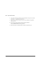
Replacement Procedures
Replacing Modules in a Dual-Redundant
Controller Configuration
Follow the instructions in this section to replace modules in a dual-redundant
controller configuration (see Figure 2–4). If you’re replacing modules in a single
controller configuration, see “Replacing Modules in a Single-Controller
Configuration,” page 2–8.
1
2
3
6
4
5
CXO6291B
Figure 2–4. Dual-Redundant Controller Configuration
Table 2–4 Description of Dual-Redundant-Controller Configuration
Location
Description
➀
EMU
➁
Controller A
➂
Controller B
➃
Cache Module B
➄
PVA Module
➅
Trilink connectors and cables
2–17
The following sections cover procedures for replacing both the controller and cache
module, replacing the controller, and replacing the cache module.
Note the following before starting the replacement procedures:
■
The new controller’s hardware must be compatible with the functioning
controller’s hardware. See the product-specific release notes that accompanied
the software release for information regarding hardware compatibility.
■
The software versions and patch levels must be the same on both controllers.
■
The new cache module must contain the same memory configuration as the
module it’s replacing.
Replacing a Controller and Cache Module in a
Dual-Redundant Controller Configuration
Use the following steps in “Removing a Controller and Cache Module in a DualRedundant Controller Configuration” and “Installing a Controller and its Cache
Module in a Dual-Redundant Controller Configuration” to replace a controller and its
cache module.
Removing a Controller and Cache Module in a DualRedundant Controller Configuration
Use the following steps to remove a controller and its cache module.
1.
Connect a PC or terminal to the operational controller’s maintenance port. The
controller to which you’re connected is “this controller”; the controller that
you’re removing is the “other controller.”
2.
Disable failover with the following command:
SET NOFAILOVER
3.
Remove the ESD cover and program card from the “other controller.” Save them
for the replacement controller.
Compaq HSZ80 Array Controller ACS Version 8.3 Maintenance and Service Guide
2–18
Replacement Procedures
4.
Start FRUTIL with the following command:
RUN FRUTIL
FRUTIL displays the following:
Do you intend to replace this controller’s cache battery? Y/N
5.
Enter N(o). FRUTIL displays the FRUTIL Main menu:
FRUTIL Main Menu:
1. Replace or remove a controller or cache module
2. Install a controller or cache module
3. Replace a PVA module
4. Replace an I/O module
5. Exit
Enter choice: 1, 2, 3, 4, or 5 ->
6.
Enter option 1, Replace or remove a controller or cache module, from the
FRUTIL Main menu. FRUTIL displays the Replace or Remove Options menu:
Replace or remove Options:
1. Other controller and cache module
2. Other controller module
3. Other cache module
4. Exit
Enter choice: 1, 2, 3, or 4 ->
7.
Enter option 1, Other controller and cache module, from the Replace or Remove
Options menu. FRUTIL displays the following:
Slot Designations
(front view)
[
---
[
--------
EMU
---
Controller A
][
-------
]
[
--------
Controller B
-------
]
[
Cache Module A
][
---
PVA
---
Cache Module B
]
]
Remove both the slot A [or B ] controller and cache module? Y/N
2–19
8.
Enter Y(es) and press return. FRUTIL displays the following:
Quiescing all device ports.
Please wait...
Device Port 1 quiesced.
Device Port 2 quiesced.
Device Port 3 quiesced.
Device Port 4 quiesced.
Device Port 5 quiesced.
Device Port 6 quiesced.
All device ports quiesced.
Remove the slot A [ or B] controller (the one without a blinking green
LED) within 4 minutes.
CAUTION: The device ports must quiesce before removing the
controller. Failure to allow the ports to quiesce may result in data loss.
Quiescing may take several minutes.
ESD can easily damage a controller, cache module, or DIMM. Wear a
snug-fitting, grounded ESD wrist strap.
NOTE: A countdown timer allows a total of four minutes to remove both the
controller and cache module. If you exceed four minutes, “this controller” will exit
FRUTIL and resume operations. If this happens, return to step 4.
9.
Remove the trilink connectors from the “other controller” but don’t disconnect
the host bus cables (or terminators) from the trilink connectors.
NOTE: One or two trilink connectors with host bus cables (or terminators) may be
attached, depending on the configuration.
10. Disengage both retaining levers and remove the “other controller,” then place the
controller into an antistatic bag or onto a grounded antistatic mat.
Once the controller is removed, FRUTIL displays the following:
Remove the slot A [or B] cache module within x minutes, xx seconds.
11. Disengage both retaining levers and partially remove the “other controller’s”
cache module—about half way.
Compaq HSZ80 Array Controller ACS Version 8.3 Maintenance and Service Guide
2–20
Replacement Procedures
12. Disable the ECB by pressing the battery disable switch until the status light stops
blinking—about five seconds.
CAUTION: The ECB must be disabled—the status light is not lit and is
not blinking—before disconnecting the ECB cable from the cache
module. Failure to disable the ECB could result in cache module
damage.
13. Disconnect the ECB cable from the “other controller’s” cache module, remove
the cache module, and place it onto a grounded antistatic mat or into an antistatic
bag.
Once the cache module is removed, FRUTIL displays the following:
Restarting all device ports. Please wait...
Device Port 1 restarted.
Device Port 2 restarted.
Device Port 3 restarted.
Device Port 4 restarted.
Device Port 5 restarted.
Device Port 6 restarted.
Do you have a replacement controller and cache module? Y/N
14. Enter N(o) if you don’t have a replacement controller and cache module;
FRUTIL will exit. Disconnect the PC or terminal from the controller’s
maintenance port.
Enter Y(es) if you have a replacement controller and cache module and want to
install it now. FRUTIL displays the following:
Insert both the slot A [or B ] controller and cache module? Y/N
NOTE: If you entered Y(es) go to step 9 on page 2–22.
Remove the DIMMs from the cache module. They will be installed in the
replacement cache module.
15. Press down on the DIMM retaining levers at either end of the DIMM you want to
remove.
2–21
16. Grasp the DIMM and gently remove it from the DIMM slot. Repeat for all
DIMMs.
Installing a Controller and its Cache Module in a DualRedundant Controller Configuration
Use the following steps to install a controller and its cache module.
CAUTION: ESD can easily damage a controller, cache module, or DIMM.
Wear a snug-fitting, grounded ESD wrist strap.
1.
Insert the DIMM straight into the socket in the replacement cache module and
ensure that the notches in the DIMM align with the tabs in the socket (see Figure
2–9).
2.
Press the DIMM gently until it’s seated in the socket.
3.
Double-check to ensure both ends of the DIMM are firmly seated in the slot and
both retaining clips engage the DIMM. Repeat for all DIMMs.
4.
Connect a PC or terminal to the operational controller. The controller to which
you’re connected is “this controller”; the controller whose cache module you’re
installing is the “other controller.”
5.
Start FRUTIL with the following command:
RUN FRUTIL
FRUTIL displays the following:
Do you intend to replace this controller’s cache battery? Y/N
6.
Enter N(o). FRUTIL displays the FRUTIL Main menu:
FRUTIL Main Menu:
1. Replace or remove a controller or cache module
2. Install a controller or cache module
3. Replace a PVA module
4. Replace an I/O module
5. Exit
Enter choice: 1, 2, 3, 4, or 5 ->
Compaq HSZ80 Array Controller ACS Version 8.3 Maintenance and Service Guide
2–22
Replacement Procedures
7.
Enter option 2, Install a controller or cache module, from the FRUTIL Main
menu. FRUTIL displays the Install Options menu:
Install Options:
1. Other controller and cache module
2. Other controller module
3. Other cache module
4. Exit
Enter choice: 1, 2, 3, or 4 ->
8.
Enter option 1, Other controller and cache module, from the Install Options
menu. FRUTIL display the following:
Insert both the slot A [or B ] controller and cache module? Y/N
9.
Enter Y(es) and press return. FRUTIL displays the following:
Quiescing all device ports.
Please wait...
Device Port 1 quiesced.
Device Port 2 quiesced.
Device Port 3 quiesced.
Device Port 4 quiesced.
Device Port 5 quiesced.
Device Port 6 quiesced.
All device ports quiesced.
.
.
.
Perform the following steps:
1. Turn off the battery for the new cache module by pressing
the battery’s shut off button for five seconds
2. Connect the battery to the new cache module.
3. Insert the new cache module in slot A [ or B] within 4
minutes.
NOTE: A countdown timer allows a total of four minutes to install both the cache
module and controller. If you exceed four minutes, “this controller” will exit FRUTIL
and resume operations. If this happens, return to step 5.
2–23
CAUTION: ESD can easily damage a controller or a cache module. Wear
a snug-fitting, grounded ESD wrist strap.
10. Disable the ECB to which you’re connecting the new cache module by pressing
the battery disable switch until the status light stops blinking—about five
seconds.
CAUTION: The ECB must be disabled—the status light is not lit and is
not blinking—before connecting the ECB cable to the cache module.
Failure to disable the ECB could result in ECB damage.
Make sure you align the cache module and controller in the appropriate
guide rails. If you do not align the modules correctly, damage to the
backplane can occur.
11. Connect the ECB cable to the new cache module.
12. Insert the new cache module into its slot and engage its retaining levers. FRUTIL
displays the following:
Insert the controller module, WITH its program card, in slot A [ or B]
within x minutes, xx seconds.
13. Ensure that the program card is in the replacement controller and insert the new
controller into its slot. Engage its retaining levers. When fully seated, the newly
installed controller will boot.
FRUTIL displays the following:
If the other controller did not restart, follow these steps:
1. Press and hold the other controller’s reset button.
2. Insert the other controller’s program card.
3. Release the reset button.
Press return to continue.
NOTE: In mirrored mode, FRUTIL will initialize the mirrored portion of the new cache
module, check for old data on the cache module, and then restart all device ports.
After the device ports have been restarted, FRUTIL will test the cache module and the
ECB. After the test completes, the device ports will quiesce and a mirror copy of the
cache module data will be created on the newly installed cache module.
Compaq HSZ80 Array Controller ACS Version 8.3 Maintenance and Service Guide
2–24
Replacement Procedures
14. Connect the trilink connectors with host bus cables (or terminators) to the new
controller.
NOTE: One or two trilink connectors with host bus cables (or terminators) may be
attached, depending on the configuration.
15. Press return to continue. FRUTIL will exit. If the other controller did not restart,
follow these steps:
a.
Press and hold the other controller’s reset button.
b.
Insert the other controller’s program card.
c.
Release the reset button.
16. See HSZ80 ACS Version 8.3 Configuration and CLI Reference Guide to configure
the controller.
NOTE: If the controller you’ve installed was previously used in another subsystem,
it will need to be purged of the controller’s old configuration (see HSZ80 ACS
Version 8.3 Configuration and CLI Reference Guide).
17. Enable failover, and re-establish the dual-redundant controller configuration with
the following command:
SET FAILOVER COPY=THIS_CONTROLLER
This command copies the subsystem’s configuration from “this controller” to the
new controller.
18. Disconnect the PC or terminal from the controller’s maintenance port.
2–25
Replacing a Controller in a Dual-Redundant
Controller Configuration
Use the following steps in “Removing a Controller in a Dual-Redundant Controller
Configuration” and “Installing a Controller in a Dual-Redundant Controller
Configuration” to replace a controller.
Removing a Controller in a Dual-Redundant Controller
Configuration
Use the following steps to remove a controller:
1.
Connect a PC or terminal to the operational controller’s maintenance port. The
controller to which you’re connected is “this controller”; the controller that
you’re removing is the “other controller.”
2.
Disable failover and take the controllers out of their dual-redundant configuration
with the following command:
SET NOFAILOVER
3.
Remove the program card’s ESD cover and program card. Save them for the
replacement controller.
4.
Start FRUTIL with the following command:
RUN FRUTIL
FRUTIL displays the following:
Do you intend to replace this controller’s cache battery? Y/N
5.
Enter N(o). FRUTIL displays the FRUTIL Main menu:
FRUTIL Main Menu:
1. Replace or remove a controller or cache module
2. Install a controller or cache module
3. Replace a PVA module
4. Replace an I/O module
5. Exit
Enter choice: 1, 2, 3, 4, or 5 ->
Compaq HSZ80 Array Controller ACS Version 8.3 Maintenance and Service Guide
2–26
Replacement Procedures
6.
Enter option 1, Replace or remove a controller or cache module, from the
FRUTIL Main menu. FRUTIL displays the Replace or Remove Options menu:
Replace or remove Options:
1. Other controller and cache module
2. Other controller module
3. Other cache module
4. Exit
Enter choice: 1, 2, 3, or 4 ->
7.
Enter option 2, Other controller module, from the Replace or Remove Options
menu. FRUTIL displays the following:
Slot Designations
(front view)
[
---
[
--------
EMU
---
Controller A
][
-------
]
[
--------
Controller B
-------
]
[
Cache Module A
][
---
PVA
---
Cache Module B
]
]
Remove the slot A [or B] controller? Y/N
8.
Type Y(es) and press return. FRUTIL displays the following:
Quiescing all device ports.
Please wait...
Device Port 1 quiesced.
Device Port 2 quiesced.
Device Port 3 quiesced.
Device Port 4 quiesced.
Device Port 5 quiesced.
Device Port 6 quiesced.
All device ports quiesced.
Remove the slot A [ or B] controller (the one without a blinking green
LED) within 2 minutes.
2–27
CAUTION: The device ports must quiesce before removing the
controller. Failure to allow the ports to quiesce may result in data loss.
Quiescing may take several minutes.
ESD can easily damage a controller. Wear a snug-fitting, grounded ESD
wrist strap.
NOTE: A countdown timer allows a total of two minutes to remove the controller. If
you exceed two minutes, “this controller” will exit FRUTIL and resume operations.
If this happens, return to step 4.
9.
Remove the trilink connectors from the “other controller,” but don’t disconnect
the host bus cables (or terminators) from the trilink connectors.
NOTE: One or two trilink connectors with host bus cables (or terminators) may be
attached, depending on the configuration.
10. Disengage both retaining levers, remove the “other controller,” and place this
controller into an antistatic bag or onto a grounded antistatic mat.
Once the controller is removed, FRUTIL displays the following:
Restarting all device ports. Please wait...
Device Port 1 restarted.
Device Port 2 restarted.
Device Port 3 restarted.
Device Port 4 restarted.
Device Port 5 restarted.
Device Port 6 restarted.
Do you have a replacement controller? Y/N
11. Enter N(o) if you don’t have a replacement controller; FRUTIL will exit.
Disconnect the PC or terminal from the controller’s maintenance port.
Enter Y(es) if you have a replacement controller and want to install it now.
FRUTIL displays the following:
Insert the slot A [or B] controller? Y/N
NOTE: If you entered Y(es) go to step 6 on page 2–29.
Compaq HSZ80 Array Controller ACS Version 8.3 Maintenance and Service Guide
2–28
Replacement Procedures
Installing a Controller in a Dual-Redundant Controller
Configuration
Use the following steps to install a controller:
1.
Connect a PC or terminal to the operational controller’s maintenance port. The
controller to which you’re connected is “this controller”; the controller that
you’re installing is the “other controller.”
2.
Start FRUTIL with the following command:
RUN FRUTIL
FRUTIL displays the following:
Do you intend to replace this controller’s cache battery? Y/N
3.
Enter N(o). FRUTIL displays the FRUTIL Main menu:
FRUTIL Main Menu:
1. Replace or remove a controller or cache module
2. Install a controller or cache module
3. Replace a PVA module
4. Replace an I/O module
5. Exit
Enter choice: 1, 2, 3, 4, or 5 ->
4.
Enter option 2, Install a controller or cache module, from the FRUTIL Main
menu. FRUTIL displays the Install Options menu:
Install Options:
1. Other controller and cache module
2. Other controller module
3. Other cache module
4. Exit
Enter choice: 1, 2, 3, or 4 ->
5.
Enter option 2, Other controller module, from the Install Options menu. FRUTIL
display the following:
Insert the slot A [or B] controller? Y/N
2–29
6.
Enter Y(es) and press return. FRUTIL displays the following:
Quiescing all device ports.
Please wait...
Device Port 1 quiesced.
Device Port 2 quiesced.
Device Port 3 quiesced.
Device Port 4 quiesced.
Device Port 5 quiesced.
Device Port 6 quiesced.
All device ports quiesced.
.
.
.
Insert the controller module, WITH its program card, in slot A [ or B]
within x minutes, xx seconds.
NOTE: A countdown timer allows a total of two minutes to install the controller. If
you exceed two minutes, “this controller” will exit FRUTIL and resume operations.
If this happens, return to step 2.
CAUTION: ESD can easily damage a controller. Wear a snug-fitting,
grounded ESD wrist strap.
Make sure you align the controller in the appropriate guide rails. If you
do not align the controller correctly, damage to the backplane can occur.
7.
Ensure that the program card is in the replacement controller and insert the new
controller into its slot. Engage its retaining levers. When fully seated, the newly
installed controller will boot.
FRUTIL displays the following:
If the other controller did not restart, follow these steps:
1. Press and hold the other controller’s reset button.
2. Insert the other controller’s program card.
3. Release the reset button.
Press return to continue.
Compaq HSZ80 Array Controller ACS Version 8.3 Maintenance and Service Guide
2–30
Replacement Procedures
8.
Connect the trilink connectors with host bus cables (or terminators) to the new
controller.
NOTE: One or two trilink connectors with host bus cables (or terminators) may be
attached, depending on the configuration.
9.
Press return to continue. FRUTIL will exit. If the other controller did not restart,
follow these steps:
a.
Press and hold the other controller’s reset button.
b.
Insert the other controller’s program card.
c.
Release the reset button.
10. See HSZ80 ACS Version 8.3 Configuration and CLI Reference Guide to configure
the controller.
NOTE: If the controller you’ve installed was previously used in another subsystem,
it will need to be purged of the controller’s old configuration (see HSZ80 ACS
Version 8.3 Configuration and CLI Reference Guide).
11. Enable failover, and re-establish the dual-redundant controller configuration with
the following command:
SET FAILOVER COPY=THIS_CONTROLLER
This command copies the subsystem’s configuration from “this controller” to the
new controller.
12. Disconnect the PC or terminal from the controller’s maintenance port.
2–31
Replacing a Cache Module in a DualRedundant Controller Configuration
Use the following steps in “Removing a Cache Module in a Dual-Redundant
Controller Configuration” and “Installing a Cache Module in a Dual-Redundant
Controller Configuration” to replace a cache module.
NOTE: The new cache module must contain the same memory configuration as
the cache module it’s replacing.
Removing a Cache Module in a Dual-Redundant
Controller Configuration
Use the following steps to remove a cache module:
1.
Connect a PC or terminal to the operational controller’s maintenance port. The
controller to which you’re connected is “this controller”; the controller that
you’re removing is the “other controller.”
2.
Disable failover and take the controllers out of their dual-redundant configuration
with the following command:
SET NOFAILOVER
3.
Start FRUTIL with the following command:
RUN FRUTIL
FRUTIL displays the following:
Do you intend to replace this controller’s cache battery? Y/N
4.
Enter N(o). FRUTIL displays the FRUTIL Main menu:
FRUTIL Main Menu:
1. Replace or remove a controller or cache module
2. Install a controller or cache module
3. Replace a PVA module
4. Replace an I/O module
5. Exit
Enter choice: 1, 2, 3, 4, or 5 ->
Compaq HSZ80 Array Controller ACS Version 8.3 Maintenance and Service Guide
2–32
Replacement Procedures
5.
Enter option 1, Replace or remove a controller or cache module, from the
FRUTIL Main menu. FRUTIL displays the Replace or Remove Options menu:
Replace or remove Options:
1. Other controller and cache module
2. Other controller module
3. Other cache module
4. Exit
Enter choice: 1, 2, 3, or 4 ->
6.
Enter option 3, Other cache module, from the Replace or Remove Options menu.
FRUTIL displays the following:
Slot Designations
(front view)
[
---
EMU
---
[
--------
Controller A
][
-------
]
[
--------
Controller B
-------
]
[
Cache Module A
][
---
PVA
---
Cache Module B
]
]
Remove the slot A [or B] cache module? Y/N
7.
Enter Y(es) and press return. FRUTIL displays the following:
Quiescing all device ports.
Please wait...
Device Port 1 quiesced.
Device Port 2 quiesced.
Device Port 3 quiesced.
Device Port 4 quiesced.
Device Port 5 quiesced.
Device Port 6 quiesced.
All device ports quiesced.
Remove the slot A [or B] cache module within 2 minutes. Then
disconnect the external battery from the cache module.
2–33
CAUTION: The device ports must quiesce before removing the cache
module. Failure to allow the ports to quiesce may result in data loss.
Quiescing may take several minutes.
ESD can easily damage the cache module or a DIMM. Wear a snugfitting, grounded ESD wrist strap.
NOTE: A countdown timer allows a total of two minutes to remove the cache
module. If you exceed two minutes, “this controller” will exit FRUTIL and resume
operations. If this happens, return to step 3.
8.
Disengage both retaining levers and partially remove the “other controller’s”
cache module—about half way.
9.
Disable the ECB by pressing the battery disable switch until the status light stops
blinking—about five seconds.
CAUTION: The ECB must be disabled—the status light is not lit and is
not blinking—before disconnecting the ECB cable from the cache
module. Failure to disable the ECB could result in cache module
damage.
10. Disconnect the ECB cable from the “other controller’s” cache module, remove
the cache module, and place it onto a grounded antistatic mat or into an antistatic
bag.
Once the cache module is removed, FRUTIL displays the following:
Restarting all device ports. Please wait...
Device Port 1 restarted.
Device Port 2 restarted.
Device Port 3 restarted.
Device Port 4 restarted.
Device Port 5 restarted.
Device Port 6 restarted.
Do you have a replacement cache module? Y/N
Compaq HSZ80 Array Controller ACS Version 8.3 Maintenance and Service Guide
2–34
Replacement Procedures
11. Enter N(o) if you don’t have a replacement cache module; FRUTIL will exit.
Disconnect the PC or terminal from the controller’s maintenance port.
Enter Y(es) if you have a replacement cache module and want to install it now.
FRUTIL displays the following:
Insert the slot A [or B] cache module? Y/N
NOTE: Remove the DIMMs from the cache module. They will be installed in the
replacement cache module.
12. Press down on the DIMM retaining levers at either end of the DIMM you want to
remove.
13. Grasp the DIMM and gently remove it from the DIMM slot. Repeat for all
DIMMs.
NOTE: If you entered Y(es) in step 11 above, go to step 6 on page 2–35.
Installing a Cache Module in a Dual-Redundant
Controller Configuration
Use the following steps to install a cache module:
CAUTION: ESD can easily damage a cache module or a DIMM. Wear a
snug-fitting, grounded ESD wrist strap.
1.
Connect a PC or terminal to the operational controller’s maintenance port. The
controller to which you’re connected is “this controller”; the controller that
you’re installing is the “other controller.”
2.
Start FRUTIL with the following command:
RUN FRUTIL
FRUTIL displays the following:
Do you intend to replace this controller’s cache battery? Y/N
2–35
3.
Enter N(o). FRUTIL displays the FRUTIL Main menu:
FRUTIL Main Menu:
1. Replace or remove a controller or cache module
2. Install a controller or cache module
3. Replace a PVA module
4. Replace an I/O module
5. Exit
Enter choice: 1, 2, 3, 4, or 5 ->
4.
Enter option 2, Install a controller or cache module, from the FRUTIL Main
menu. FRUTIL displays the Install Options menu:
Install Options:
1. Other controller and cache module
2. Other controller module
3. Other cache module
4. Exit
Enter choice: 1, 2, 3, or 4 ->
5.
Enter option 3, Other cache module, from the Install Options menu. FRUTIL
display the following:
Insert the slot A [or B] cache module? Y/N
NOTE: Use the DIMMs that were removed from the old cache module for the
replacement cache module.
6.
Insert the DIMM straight into the socket in the replacement cache module and
ensure that the notches in the DIMM align with the tabs in the socket (see Figure
2–9).
7.
Press the DIMM gently until it’s seated in the socket.
8.
Double-check to ensure both ends of the DIMM are firmly seated in the slot and
both retaining clips engage the DIMM. Repeat for all DIMMs.
Compaq HSZ80 Array Controller ACS Version 8.3 Maintenance and Service Guide
2–36
Replacement Procedures
9.
Enter Y(es) and press return. FRUTIL displays the following:
Quiescing all device ports.
Please wait...
Device Port 1 quiesced.
Device Port 2 quiesced.
Device Port 3 quiesced.
Device Port 4 quiesced.
Device Port 5 quiesced.
Device Port 6 quiesced.
All device ports quiesced.
.
.
.
Perform the following steps:
1. Turn off the battery for the new cache module by pressing
the battery’s shut off button for five seconds
2. Connect the battery to the new cache module.
3. Insert the new cache module in slot A [ or B] within 2
minutes.
NOTE: A countdown timer allows a total of two minutes to install the cache
module. If you exceed two minutes, “this controller” will exit FRUTIL and resume
operations. If this happens, return to step 2.
CAUTION: Make sure you align the cache module in the appropriate
guide rails. If you do not align the cache module correctly, damage to the
backplane can occur.
10. Disable the ECB to which you’re connecting the new cache module by pressing
the battery disable switch until the status light stops blinking—about five
seconds.
CAUTION: The ECB must be disabled—the status light is not lit and is
not blinking—before connecting the ECB cable to the cache module.
Failure to disable the ECB could result in ECB damage.
11. Connect the ECB cable to the new cache module.
12. Insert the new cache module into its slot and engage its retaining levers.
2–37
NOTE: In mirrored mode, FRUTIL will initialize the mirrored portion of the new
cache module, check for old data on the cache module, and then restart all device
ports. After the device ports have been restarted, FRUTIL will test the cache module
and the ECB. After the test completes, the device ports will quiesce and a mirror
copy of the cache module data will be created on the newly installed cache
module.
13. FRUTIL will restart the other controller. FRUTIL displays the following:
Please wait . . .
If the other controller did not restart, press its reset button.
Field Replacement Utility terminated.
14. If the other controller did not restart, press its reset button.
15. Enable failover, and re-establish the dual-redundant configuration with the
following command:
SET FAILOVER COPY=THIS_CONTROLLER
This command copies the subsystem’s configuration from “this controller” to the
“other controller.”
16. Disconnect the PC or terminal from the controller’s maintenance port.
Compaq HSZ80 Array Controller ACS Version 8.3 Maintenance and Service Guide
2–38
Replacement Procedures
Replacing an External Cache Battery Storage
Building Block
The External Cache Battery (ECB) Storage Building Block (SBB) can be replaced
with cabinet power on or off. An ECB SBB is shown in Figure 2–5. The singlebattery configuration contains one battery and the dual-battery configuration contains
two batteries.
1
2
US
STAT
F
OF
UT
SH
E
CH
CA
R
WE
PO
E
CH
CA
R
WE
PO
US
STAT
F
OF
UT
SH
4
3
~
CXO5713A
Figure 2–5. ECB SBB Configuration
Table 2–5 ECB SBB Configuration
➀
Battery disable switch
➁
Status LED
➂
ECB Y cable
④
Faceplate and controls for second battery
(dual-battery configuration only)
2–39
Replacing an External Cache Battery Storage
Building Block With Cabinet Powered On
Use the following steps to replace the ECB SSB with the cabinet powered on:
NOTE: The procedure for a dual-redundant controller configuration assumes that a
single ECB SBB with a dual battery is installed and an empty slot is available for the
replacement ECB SBB. If an empty slot is not available, place the new ECB SBB on
the top of the enclosure. After the old ECB SBB has been removed, carefully insert
the new ECB SBB into the empty slot.
1.
Connect a PC or terminal to the controller with the ECB SBB that you intend to
replace. The controller to which you’re connected is “this controller.”
2.
Start FRUTIL with the following command:
RUN FRUTIL
FRUTIL displays the following:
Do you intend to replace this controller’s cache battery? Y/N
3.
Enter Y(es). FRUTIL displays the following:
If the batteries were replaced while the cabinet was powered
down, press return.
Otherwise follow this procedure:
WARNING: Ensure that at least one battery is connected to the
Y cable at all times during this procedure.
1.Connect the new battery to the unused end of the 'Y' cable
attached to cache A [or B].
2.Disconnect the old battery.
Do not wait for the new
battery's status light to turn solid green.
3.Press return.
CAUTION: The ECB cable has a 12-volt and a 5-volt pin. Improper
handling or misalignment when connecting or disconnecting could
cause these pins to contact ground, resulting in cache module damage.
4.
Insert the new ECB SBB into the empty battery slot.
Compaq HSZ80 Array Controller ACS Version 8.3 Maintenance and Service Guide
2–40
Replacement Procedures
NOTE: If an empty slot is not available, place the new ECB SBB on the top of the
enclosure.
5.
Connect the new battery to the unused end of the Y cable attached to cache A [or
B]
6.
Disconnect the old battery. Do not wait for the new battery’s status light to turn
solid green.
7.
Press return.
FRUTIL displays the following:
Updating this battery’s expiration date and deep discharge history.
Field Replacement Utility terminated.
8.
Disconnect the PC or terminal from the controller’s maintenance port.
9.
If this is a dual-redundant controller configuration and you installed a dualbattery ECB SBB and you want to connect the other cache module to the new
ECB SBB, connect the PC or terminal to the other controller’s maintenance port.
The controller to which you’re now connected is “this controller.”
10. Repeat steps 2 through 8.
11. Remove the old ECB SBB.
NOTE: If an empty slot was not available, and the new ECB SBB was placed on the
top of the enclosure, carefully insert it now into the empty slot.
Replacing an External Cache Battery Storage
Building Block With Cabinet Powered Off
Use the following steps to replace the ECB SSB with the cabinet powered off:
1.
If the controller and cache module are not operating, go to step 4. Otherwise, go
to the next step.
2.
Connect a PC or terminal to the controller’s maintenance port. The controller to
which you’re connected is “this controller.”
2–41
3.
Shut down the controllers. In single-controller configurations, shut down “this
controller.” In dual-redundant controller configurations, shut down the “other
controller” first, then shut down “this controller” with the following commands:
SHUTDOWN OTHER_CONTROLLER
SHUTDOWN THIS_CONTROLLER
When the controllers shut down, their reset buttons and their first three LEDs are
lit continuously. This may take several minutes, depending on the amount of data
that needs to be flushed from the cache modules.
4.
Turn off the power to the subsystem.
5.
Insert the new ECB SBB into its slot.
CAUTION: The ECB cable has a 12-volt and a 5-volt pin. Improper
handling or misalignment when connecting or disconnecting could
cause these pins to contact ground, resulting in cache module damage.
6.
Connect the open end of the ECB Y cable to the new ECB.
7.
Restore power to the subsystem. The controller automatically restarts.
8.
Disconnect the ECB cable from the old ECB.
9.
Start FRUTIL with the following command:
RUN FRUTIL
FRUTIL displays the following:
Do you intend to replace this controller’s cache battery? Y/N
Compaq HSZ80 Array Controller ACS Version 8.3 Maintenance and Service Guide
2–42
Replacement Procedures
10. Type Y(es). FRUTIL displays the following:
If the batteries were replaced while the cabinet was powered
down, press return.
Otherwise follow this procedure:
WARNING: Ensure that at least one battery is connected to the
Y cable at all times during this procedure.
1.Connect the new battery to the unused end of the ’Y’ cable
attached to cache A [or B].
2.Disconnect the old battery.
Do not wait for the new
battery’s status light to turn solid green.
3.Press return.
11. Press return.
FRUTIL displays the following:
Updating this battery’s expiration date and deep discharge history.
Field Replacement Utility terminated.
12. Disconnect the PC or terminal from the controller’s maintenance port.
13. In a dual-redundant controller configuration and if the ECB was replaced for both
cache modules, connect the PC or terminal to the other controller’s maintenance
port. The controller to which you’re now connected is “this controller.”
14. Repeat steps 9 through 12.
15. Remove the old ECB SBB.
2–43
Replacing a PVA Module
Use the following steps to replace a PVA module in the master enclosure (ID 0), the
first expansion (ID 2), or second expansion enclosure (ID 3). The master enclosure
contains the controllers and the cache modules.
NOTE: This procedure is not applicable for the M1 shelf.
The HSZ80 controller can support up to three enclosures: the master enclosure, the
first expansion enclosure, and the second expansion enclosure.
A PVA can be replaced in either a single or a dual-redundant controller
configuration using this procedure.
1.
Connect a PC or terminal to the controller’s maintenance port.
2.
In a dual-redundant controller configuration, disable failover with the following
command:
SET NOFAILOVER
3.
Start FRUTIL with the following command:
RUN FRUTIL
FRUTIL displays the following:
Do you intend to replace this controller’s cache battery? Y/N
4.
Enter N(o). FRUTIL displays the FRUTIL Main menu:
FRUTIL Main Menu:
1. Replace or remove a controller or cache module
2. Install a controller or cache module
3. Replace a PVA module
4. Replace an I/O module
5. Exit
Enter choice: 1, 2, 3, 4, or 5 ->
Compaq HSZ80 Array Controller ACS Version 8.3 Maintenance and Service Guide
2–44
Replacement Procedures
5.
Enter option 3, Replace a PVA module from the FRUTIL Main menu. FRUTIL
displays the PVA Replacement menu:
FRUTIL PVA Replacement Menu:
1. Master Enclosure (ID 0)
2. First Expansion Enclosure (ID 2)
3. Second Expansion Enclosure (ID 3)
4. Exit
Enter Choice: 1, 2, 3, or 4 ->
NOTE: The HSZ80 controller supports up to three enclosures. The FRUTIL PVA
Replacement Menu has options for three enclosures regardless of how many
enclosures are connected.
6.
Enter option 1, Master Enclosure (ID 0), to replace the PVA in the master
enclosure; enter option 2, First Expansion Enclosure (ID 2), to replace the PVA
in the first expansion enclosure; or enter option 3, Second Expansion Enclosure
(ID 3), to replace the PVA in the second expansion enclosure from the FRUTIL
PVA Replacement menu. FRUTIL displays the following:
Do you have a replacement PVA module? Y/N
7.
Enter Y(es) and press return. FRUTIL displays the following:
Ensure the replacement PVA’s address is set to zero.
Press return to quiesce device port activity.
8.
Set the replacement PVA’s address to zero for the master enclosure, to 2 for the
first expansion enclosure, or to 3 for the second expansion enclosure.
9.
Press return and wait for FRUTIL to quiesce the device ports. This may take
several minutes. FRUTIL displays the following:
All device ports quiesced.
Replace the PVA in the master cabinet.
Press return to resume device port activity.
10. Remove the old PVA and install the new PVA.
2–45
11. Press return to resume device port activity and restart the other controller. When
all port activity has restarted, FRUTIL displays the following:
PVA replacement complete.
Please wait . . .
If the other controller did not restart, press its reset button.
Field Replacement Utility terminated.
12. If the other controller did not restart, press its reset button.
13. Enable failover and re-establish the dual-redundant configuration with the
following command:
SET FAILOVER COPY=THIS_CONTROLLER
This command copies the subsystem’s configuration from “this controller” to the
“other controller.”
14. Disconnect the PC or terminal from the controller’s maintenance port.
Compaq HSZ80 Array Controller ACS Version 8.3 Maintenance and Service Guide
2–46
Replacement Procedures
Replacing an I/O Module
Figure 2–6 shows a rear view of the BA370 enclosure and the relative location of the
six I/O modules (also referred to as ports). Figure 2–7 shows the six I/O modules and
the location of the connectors and securing screws. Use the following steps to replace
an I/O module:
NOTE: This procedure is not applicable for the M1 shelf.
An I/O module can be replaced in either a single-controller or a dual-redundant
controller configuration using this procedure.
1
2
4
6
5
1
3
2
CXO6575A
Figure 2–6. I/O Module Locations in a BA370 Enclosure
Table 2–6 Description of I/O Modules in a BA370 Enclosure
Location
Description
➀
Fans
➁
I/O Modules (6 each)
2–47
6
4
2
5
3
1
CXO5819A
Figure 2–7. I/O Module Locations
NOTE: The controller can function with one failed I/O module.
1.
Connect a PC or terminal to the controller’s maintenance port.
2.
In a dual-redundant controller configuration, disable failover with the following
command:
SET NOFAILOVER
3.
Start FRUTIL with the following command:
RUN FRUTIL
FRUTIL displays the following:
Do you intend to replace this controller’s cache battery? Y/N
4.
Enter N(o). FRUTIL displays the FRUTIL Main menu:
FRUTIL Main Menu:
1. Replace or remove a controller or cache module
2. Install a controller or cache module
3. Replace a PVA module
4. Replace an I/O module
5. Exit
Enter choice: 1, 2, 3, 4, or 5 ->
NOTE: The HSZ80 controller supports up to three enclosures. The I/O Module
status can show the following states: Single Ended – OK, Differential – OK,
Termination only – OK, Missing or bad, Unknown or bad, or N/A (cabinet is not
present).
Compaq HSZ80 Array Controller ACS Version 8.3 Maintenance and Service Guide
2–48
Replacement Procedures
5.
Enter option 4, Replace an I/O module, from the FRUTIL Main menu. In the
following example, cabinet 0, port 5 is missing or bad. FRUTIL displays the
following:
I/O Module Status:
Cabinet 0
Cabinet 2
--------------------------------Port 1: Single Ended - OK
N/A
Port 2: Single Ended - OK
N/A
Port 3: Single Ended - OK
N/A
Port 4: Single Ended - OK
N/A
Port 5: Missing or bad
N/A
Port 6: Single Ended - OK
N/A
Is the replacement I/O module available? Y/N
Cabinet 3
-----------------N/A
N/A
N/A
N/A
N/A
N/A
6.
Enter Y(es) and press return.
7.
Wait for FRUTIL to quiesce the device ports. After the ports have been quiesced
(this may take several minutes), FRUTIL displays the following:
All device ports quiesced.
Press return when the new I/O module is installed.
CAUTION: If you remove the incorrect module, the controller will crash.
8.
Disconnect the cables (there may be one or two) from the appropriate
I/O module.
9.
Remove the failed I/O module.
10. Install a new I/O module.
11. Connect the cables (there may be one or two) to the I/O module.
12. Press return to resume device port activity and restart the other controller. When
all port activity has restarted, FRUTIL displays the following:
I/O module replacement complete.
Please wait . . .
If the other controller did not restart, press its reset button.
2–49
13. If the other controller did not restart, press its reset button.
14. Enable failover and re-establish the dual-redundant configuration with the
following command:
SET FAILOVER COPY=THIS_CONTROLLER
This command copies the subsystem’s configuration from “this controller” to the
“other controller.”
15. Disconnect the PC or terminal from the controller’s maintenance port.
Compaq HSZ80 Array Controller ACS Version 8.3 Maintenance and Service Guide
2–50
Replacement Procedures
Replacing an EMU
Use the following steps in and to replace the EMU.
Removing an EMU
1.
From a host console, stop all host activity and dismount the logical units in the
subsystem.
2.
Connect a PC or terminal to the maintenance port of one of the controllers in
your subsystem.
3.
Shut down the controllers. In single controller configurations, you only need to
shut down “this controller.” In dual-redundant controller configurations, shut
down the “other controller” first, then shut down “this controller” with the
following commands:
SHUTDOWN OTHER_CONTROLLER
SHUTDOWN THIS_CONTROLLER
When the controllers shut down, their reset buttons and their first three LEDs are
lit continuously. This may take several minutes, depending on the amount of data
that needs to be flushed from the cache modules.
4.
Turn off all the ac input boxes for each expansion enclosure.
CAUTION: ESD can easily damage an EMU. Wear a snug-fitting,
grounded ESD wrist strap.
5.
Disengage both retaining levers and remove the EMU.
2–51
Installing an EMU
CAUTION: ESD can easily damage an EMU. Wear a snug-fitting,
grounded ESD wrist strap.
Make sure you align the EMU in the appropriate guide rails. If you do not
align the EMU correctly, damage to the backplane can occur
1.
Align the EMU in the top, left-hand slot and insert it.
2.
Insert the EMU into its slot until the extractor latches engage the enclosure, then
Engage its retaining levers to secure the EMU.
3.
If there are no expansion enclosures, go to step 6.
If there are expansion enclosures, turn on all the ac input boxes for each expansion enclosure.
4.
Turn on all the ac input boxes for the master enclosure.
5.
If not already connected, connect a PC or terminal to the controller’s
maintenance port.
6.
Mount the logical units on the host. If you are using a Windows NT platform,
restart the server.
7.
Set the subsystem date and time with the following command:
SET THIS_CONTROLLER TIME=dd-mmm-yyyy:hh:mm:ss
8.
Disconnect the PC or terminal from the controller’s maintenance port.
Compaq HSZ80 Array Controller ACS Version 8.3 Maintenance and Service Guide
2–52
Replacement Procedures
Replacing DIMMs
Use the following steps in “Removing DIMMs” and “Installing DIMMs” to replace
DIMMs in a cache module. The cache module may be configured as shown in Figure
2–8 and Table 2–7.
3
1
4
2
CXO6576A
Figure 2–8. Cache-Module Memory Configurations
Table 2–7 Cache Module Memory Configurations
Memory
DIMMs
Quantity
Location
64 MB
32 MB
2
➀➂
128 MB
32 MB
4
➀➁➂➃
256 MB
128 MB
2
➀➂
512 MB
128 MB
4
➀➁➂➃
NOTE: If a DIMM fails, note which DIMM you need to replace based on the diagram
that displays on the console.
2–53
CAUTION: ESD can easily damage a cache module or a DIMM. Wear a
snug-fitting, grounded ESD wrist strap.
Removing DIMMs
Use the following steps to remove a DIMM from a cache module:
1.
Remove the cache module using the steps in either “Removing the Cache Module
in a Single-Controller Configuration,” page 2–13, or “Removing a Cache Module
in a Dual-Redundant Controller Configuration,” page 2–31.
2.
Press down on the DIMM retaining levers at either end of the DIMM you want to
remove.
3.
Grasp the DIMM and gently remove it from the DIMM slot.
Installing DIMMs
Use the following steps to install a DIMM in a cache module:
1.
Insert the DIMM straight into the socket and ensure that the notches in the
DIMM align with the tabs in the socket (see Figure 2–9).
2.
Press the DIMM gently until it’s seated in the socket.
3.
Double-check to ensure both ends of the DIMM are firmly seated in the slot and
both retaining clips engage the DIMM.
4.
Install the cache module using the steps in either “Installing the Cache Module in
a Single-Controller Configuration,” page 2–14, or “Installing a Cache Module in
a Dual-Redundant Controller Configuration,” page 2–34.
Compaq HSZ80 Array Controller ACS Version 8.3 Maintenance and Service Guide
2–54
Replacement Procedures
1
2
3
CXO6577A
Figure 2–9. DIMM Components
Table 2–8 DIMM Components
Location
Description
➀
DIMM
➁
DIMM Slot
➂
DIMM Retaining Clip
2–55
Replacing a PCMCIA Card
Use the following steps to replace a PCMCIA (program) card (see Figure 2–10):
1
2
3
4
1
2
3
4
5
6
5
CXO6585A
Figure 2–10. PCMCIA Card
Table 2–9 PCMCIA Card
Location
Description
➀
Controller
➁
Program-card slot
➂
Program-card ejection button
➃
Program card
➄
ESD/PCMCIA card cover
CAUTION: The new PCMCIA card must have the same software version
as the PCMCIA card being replaced. See Chapter 3, “Upgrading the
Subsystem,” for more information.
Compaq HSZ80 Array Controller ACS Version 8.3 Maintenance and Service Guide
2–56
Replacement Procedures
1.
From a host console, stop all host activity and dismount the logical units in the
subsystem.
2.
Connect a maintenance PC or terminal to one of the controllers’ maintenance
port in your subsystem.
3.
Shut down the controllers. In single-controller configurations, shut down “this
controller.” In dual-redundant controller configurations, shut down the “other
controller” first, then shut down “this controller” with the following commands:
SHUTDOWN OTHER_CONTROLLER
SHUTDOWN THIS_CONTROLLER
When the controllers shut down, their reset buttons and their first three LEDs are
lit continuously. This may take several minutes, depending on the amount of data
that needs to be flushed from the cache modules.
4.
Remove the ESD program card cover on “this controller.”
5.
Press and hold the reset button while ejecting the program card from “this
controller” by pressing the program-card eject button.
6.
Press and hold the reset button while inserting the new program card; “this
controller” automatically restarts. The controller is ready to handle I/O when the
CLI is responsive.
7.
Replace the ESD program card cover on “this controller.”
The controller restarts. Your subsystem is now ready for operation.
8.
In a dual-redundant controller configuration, repeat steps 4 through 7 for the
“other controller.”
2–57
Replacing a Failed Storageset Member
If a disk drive fails in a RAIDset or mirrorset, the controller automatically places it
into the failedset. If the spareset contains a replacement drive that satisfies the
storageset’s replacement policy, the controller automatically replaces the failed
member with the replacement drive. If the spareset is empty or doesn’t contain a
satisfactory drive, the controller simply “reduces” the storageset so that it can operate
without one of its members.
The storageset remains in this reduced state until the spareset contains a satisfactory
drive. When the controller senses a satisfactory drive in the spareset, it automatically
places the drive into the storageset and restores the storageset to normal. Therefore,
replacing a failed storageset member means putting a satisfactory drive into the
spareset.
Removing a Failed RAIDset or Mirrorset
Member
Use the following steps to remove a failed RAIDset or mirrorset member:
1.
Connect a PC or terminal to the maintenance port of the controller that accesses
the reduced RAIDset or mirrorset.
2.
Enable AUTOSPARE with the following command:
SET FAILEDSET AUTOSPARE
With AUTOSPARE enabled, any new disk drive—one that has not been in an
array before—that you insert into the PTL location of a failed disk drive is
automatically initialized and placed into the spareset.
3.
Remove the failed disk drive.
Compaq HSZ80 Array Controller ACS Version 8.3 Maintenance and Service Guide
2–58
Replacement Procedures
Installing the New Member
Use the following steps to install a new member:
1.
Insert a new disk drive that satisfies the replacement policy of the reduced
storageset into the PTL location of the failed disk drive.
NOTE: The controller automatically initializes the new disk drive and places it into
the spareset. As soon as it becomes a member of the spareset, the controller
automatically uses the new disk drive to restore the reduced RAIDset or mirrorset.
If initialization fails, the new disk drive is placed into the failedset.
3–1
Chapter 3
Upgrading the Subsystem
This chapter provides instructions for upgrading the controller software, installing
software patches, upgrading firmware on a device, upgrading from a single-controller
configuration to a dual-redundant controller configuration, and upgrading cache
memory.
Required Tools
You will need the following tools to service the controller, cache module, and the
external cache battery (ECB):
■
An antistatic wrist strap.
■
An antistatic mat on which to place modules during upgrading.
■
A Storage Building Block (SBB) Extractor for removing StorageWorks building
blocks. This tool is not required, but it will enable you to perform more
efficiently.
Electrostatic Discharge
Electrostatic discharge (ESD) is a common problem and may cause data loss, system
down time, and other problems. The most common source of static electricity is the
movement of people in contact with carpets and clothing. Low humidity also
increases the amount of static electricity. You must discharge all static electricity
prior to touching electronic equipment. Follow the precautions in the “Electrostatic
Discharge Precautions” given in the Preface whenever you are installing any
component.
Compaq HSZ80 Array Controller ACS Version 8.3 Maintenance and Service Guide
3–2
Upgrading the Subsystem
Upgrading Controller Software
You can upgrade the controller’s software two ways:
■
Install a new program card (see Figure 3–1) that contains the new software.
■
Download a new software image, and use the menu-driven Code Load/Code
Patch (CLCP) utility to write it onto the existing program card. You may also use
this utility to install, delete, and list patches to the controller software.
1
2
3
4
1
2
3
4
5
6
5
CXO6585A
Figure 3–1. PCMCIA Card
Table 3–1 PCMCIA Card
Location
Description
➀
Controller
➁
Program-card slot
➂
Program-card ejection button
➃
Program card
➄
ESD/PCMCIA card cover
3–3
Installing a New Program Card
Use the following steps to install a program card that contains the new software. If
you’re only upgrading the software in a single-controller configuration, disregard
references to the “other controller” and read the plural controllers as the singular
controller.
To upgrade the software by installing a new program card:
1.
From the host console, dismount the storage units in the subsystem.
2.
Connect a PC or terminal to one of the controllers’ maintenance port.
3.
Shut down the controllers. In single-controller configurations, shut down “this
controller.” In dual-redundant controller configurations, shut down the “other
controller” first, then shut down “this controller” with the following commands:
SHUTDOWN OTHER_CONTROLLER
SHUTDOWN THIS_CONTROLLER
When the controllers shut down, their reset buttons and their first three LEDs are
lit continuously. This may take several minutes, depending on the amount of data
that needs to be flushed from the cache modules.
CAUTION: Do not change the subsystem’s configuration or replace any
of its modules until you’ve completed this procedure to upgrade the
controller software.
4.
Remove the program card’s ESD cover on “this controller.”
5.
Press and hold the reset button while ejecting the program card from “this
controller” by pressing the program card eject button.
6.
Press and hold the reset button while inserting the new program card; “this
controller” automatically restarts. The controller is ready to handle I/O when the
CLI is responsive.
7.
Replace the ESD program card cover on “this controller.”
Compaq HSZ80 Array Controller ACS Version 8.3 Maintenance and Service Guide
3–4
Upgrading the Subsystem
8.
In a dual-redundant controller configuration, repeat steps 4 through 7 for the
“other controller.”
9.
Mount the storage units on the host.
Downloading New Software
Use the CLCP to download new software to the program card while it’s installed in
the controller. Use the following steps to upgrade the software with CLCP:
1.
Obtain the new software image file from a customer service representative.
NOTE: The image file can also be loaded by using StorageWorks Command
Console (SWCC) (see the SWCC documentation).
2.
Load the image onto a PC or workstation using its file- or network-transfer
capabilities.
3.
From a host console, quiesce all port activity and dismount the storage units in
the subsystem.
NOTE: Do not remove the program card.
4.
Remove the ESD cover. If your program card is equipped with a write-protection
switch, disable write-protection by sliding the switch to the left, as shown in
Figure 3–2.
5.
Connect a PC or terminal to the controller’s maintenance port.
3–5
Write
protected
Write
CXO5873A
Figure 3–2. Location of Write-Protection Switch
6.
Start CLCP with the following command:
RUN CLCP
CLCP displays the following:
Select an option from the following list:
Code Load & Patch local program Main Menu
0: Exit
1: Enter Code LOAD local program
2: Enter Code PATCH local program
3: Enter EMU Code LOAD Utility
Enter option number
(0..3) [0] ?
Compaq HSZ80 Array Controller ACS Version 8.3 Maintenance and Service Guide
3–6
Upgrading the Subsystem
7.
Enter option 1, Enter Code LOAD local program, from the CLCP Main menu to
start the Code LOAD local program. CLCP displays the following:
You have selected the Code Load Utility. This utility is used to load
a new software image into the program card currently inserted in the
controller.
Type ^Y or ^C (then RETURN) at any time to abort code load.
The code image may be loaded using SCSI Write Buffer commands through
the SCSI Host Port, or using KERMIT through the maintenance terminal
port.
0: Exit
1: Use the SCSI Host Port
2: Use the Maintenance Terminal Port
Enter option number (0..2) [0] ?
NOTE: You can use either the SCSI host port (if your operating sysem supports it) or
the maintenance port. To use the SCSI host port, go to step 8. To use the
maintenance port, go to step 10.
8.
Enter option 1, Use the SCSI Host Port, from the menu. CLCP displays the
following:
WARNING: proceeding with Controller Code Load will overwrite
the current Controller code image with a new image.
Do you want to continue (y/n) [n]: ?
9.
Enter Y(es) and the download starts. When the download is complete, CLCP
writes the new image to the program card and restarts the controller. This process
takes one to three minutes. Go to step 15.
3–7
10. Enter option 2, Use the Maintenance Terminal Port, from the menu. CLCP
displays the following:
Perform the following steps before continuing:
* get new image file on serial line host computer
* configure KERMIT with the following parameters:
terminal speed 19200 baud, eight bit, no parity, 1 stop bit
It will take approximately 35 to 45 minutes to perform the code load
operation.
WARNING: proceeding with Controller Code Load will overwrite
the current Controller code image with a new image.
Do you want to continue (y/n) [n]: ?
11. Enter Y(es) and CLCP displays:
Start KERMIT now...
12. Connect the PC to the controller’s maintenance port.
13. Configure the KERMIT transfer protocol on the PC to 19200 baud, eight bits, no
parity, and one stop bit.
14. Use KERMIT to transfer the binary image from the PC to the controller.
When the download is complete, CLCP automatically writes the new image to
the program card and restarts the controller.
15. Verify that the controller is running the new software version with the following
command:
SHOW THIS CONTROLLER
16. If your program card is equipped with a write-protection switch, re-enable writeprotection by sliding the switch to the right.
17. Replace the program card’s ESD cover.
18. Repeat the procedure to upgrade the other controller in dual-redundant
subsystems.
19. Mount the storage units in the subsystem.
Compaq HSZ80 Array Controller ACS Version 8.3 Maintenance and Service Guide
3–8
Upgrading the Subsystem
Using CLCP to Install, Delete, and List
Software Patches
Use CLCP to manage software patches. These small programming changes are placed
into the controller’s non-volatile memory and become active as soon you restart the
controller. There is space for about ten patches, depending upon the size of the
patches you’re installing.
Keep the following points in mind while installing or deleting patches:
■
Patches are associated with specific software versions. CLCP verifies the patch
against the currently installed version.
■
Patches are sequential: patch one must be entered before patch two, and so on.
■
Deleting one patch also deletes all higher-numbered patches. For example, if you
delete patch two, you’ll automatically delete patches three, four, and so on.
■
Controllers in a dual-redundant configuration must have the same patches. You
must install patches into each controller separately.
Installing a Software Patch
Use the following steps to install a software patch:
1.
Obtain the patch file from a customer service representative or via the Internet at:
http://www.storage.digital.com/menusupport.htm.
2.
Connect a PC or terminal to the controller’s maintenace port.
3.
From the host console, quiesce all port activity.
4.
Start CLCP with the following command:
RUN CLCP
3–9
CLCP displays the following:
Select an option from the following list:
Code Load & Patch local program Main Menu
0: Exit
1: Enter Code LOAD local program
2: Enter Code PATCH local program
3: Enter EMU Code LOAD utility
Enter option number
5.
(0..3) [0] ?
Enter option 2, Enter Code PATCH local program. CLCP displays the following:
You have selected the Code Patch local program. This program is used
to manage software code patches. Select an option from the following
list:
Type ^Y or ^C (then RETURN) at any time to abort Code Patch.
Code Patch Main Menu
0: Exit
1: Enter a Patch
2: Delete Patches
3: List Patches
Enter option number (0..3) [0] ?
6.
Enter option 1, Enter a Patch, to install a patch. CLCP displays the following:
This is the Enter a Code Patch option.
The program prompts you for
the patch information, one line at time.
Be careful to enter the
information exactly as it appears on the patch release. Patches may
be installed for any version of software; however, patches entered
for software versions other than XXXXX are not applied until the
matching version of software is installed.
To enter any patch, you must first install all patches with lower
patch numbers than the patch you are entering, beginning with patch
number 1, for a specific software version. If you incorrectly enter
the patch information, you are given the option to review the patch
one line at a time.
Type ^Y or ^C (then RETURN) at any time to abort Code Patch.
Do you wish to continue (y/n) [y] ?
Compaq HSZ80 Array Controller ACS Version 8.3 Maintenance and Service Guide
3–10
Upgrading the Subsystem
7.
Enter Y(es) and follow the on-screen prompts.
8.
After the patch is installed, press the controller’s reset button to restart the
controller.
Deleting a Software Patch
Use the following steps to delete a software patch:
1.
From a host console, quiesce all port activity.
2.
Connect a PC or terminal to the controller’s maintenance port.
3.
Start CLCP with the following command:
RUN CLCP
CLCP displays the following:
Select an option from the following list:
Code Load & Patch local program Main Menu
0: Exit
1: Enter Code LOAD local program
2: Enter Code PATCH local program
3: Enter EMU Code LOAD utility
Enter option number
4.
(0..3) [0] ?
Enter option 2, Enter Code PATCH local program. CLCP displays the following:
You have selected the Code Patch local program. This program is used
to manage software code patches. Select an option from the following
list:
Type ^Y or ^C (then RETURN) at any time to abort Code Patch.
Code Patch Main Menu
0: Exit
1: Enter a Patch
2: Delete Patches
3: List Patches
Enter option number (0..3) [0] ?
3–11
5.
Enter option 2, Delete Patches, to delete patches. CLCP displays the following:
This is the Delete Patches option.
The program prompts you for the
software version and patch number you wish to delete.
If you select
a patch for deletion that is required for another patch, all dependent
patches are also selected for deletion.
The program lists your
deletion selections and asks if you wish to continue.
Type ^Y or ^C (then RETURN) at any time to abort Code Patch.
The following patches are currently stored in the patch area:
Software Version - Patch number(s)
xxxx
xxxx
Currently, xx% of the patch area is free.
Software Version of patch to delete ?
6.
Enter the software version of the patch to delete and press return. CLCP displays
the following:
Patch Number to delete ?
7.
Enter the patch number to delete and press return. CLCP displays the following:
The following patches have been selected for deletion:
Software Version - Patch #
xxxx
xxxx
Do you wish to continue (y/n) [n] ?
8.
Enter Y(es) and the patches are deleted. CLCP displays the following:
Code Patch Main Menu
0: Exit
1: Enter a Patch
2: Delete Patches
3: List Patches
Enter option number (0..3) [0] ?
9.
Enter option 0, Exit.
10. Press the controller’s reset button to restart the controller.
Compaq HSZ80 Array Controller ACS Version 8.3 Maintenance and Service Guide
3–12
Upgrading the Subsystem
Listing Software Patches
Use the following steps to list software patches:
1.
Connect a PC or terminal to the controller’s maintenance port.
2.
Start CLCP with the following command:
RUN CLCP
CLCP displays the following:
Select an option from the following list:
Code Load & Patch local program Main Menu
0: Exit
1: Enter Code LOAD local program
2: Enter Code PATCH local program
3: Enter EMU Code LOAD utility
Enter option number
3.
(0..3) [0] ?
Enter option 2, Enter Code PATCH local program. CLCP displays the following:
You have selected the Code Patch local program. This program is used
to manage software code patches. Select an option from the following
list:
Type ^Y or ^C (then RETURN) at any time to abort Code Patch.
Code Patch Main Menu
0: Exit
1: Enter a Patch
2: Delete Patches
3: List Patches
Enter option number (0..3) [0] ?
3–13
4.
Enter option 3, List Patches, to list patches. CLCP displays the following:
The following patches are currently stored in the patch area:
Software Version - Patch number(s)
xxxx
xxxx
Code Patch Main Menu
0: Exit
1: Enter a Patch
2: Delete Patches
3: List Patches
Enter option number (0..3) [0] ?
5.
Enter option 0, Exit.
Compaq HSZ80 Array Controller ACS Version 8.3 Maintenance and Service Guide
3–14
Upgrading the Subsystem
Upgrading Firmware on a Device
Use HSUTIL to upgrade a device with firmware located in contiguous blocks at a
specific LBN on a source disk drive configured as a unit on the same controller.
Upgrading firmware on a disk is a two-step process as shown in Figure 3–3. First,
copy the new firmware from your host to a disk drive configured as a unit in your
subsystem, then use HSUTIL to load the firmware onto the devices in the subsystem.
Copy software
image from host
Use HSUTIL to
download software
image to devices
CXO5606A
Figure 3–3. Upgrading Device Firmware
Keep the following points in mind while using HSUTIL to upgrade firmware on a
device:
■
HSUTIL has been tested with the qualified devices listed in the product-specific
release notes that accompanied the software release. You may attempt to install
firmware on unsupported devices—HSUTIL won’t prevent this—but if the
upgrade fails, the device may be rendered unusable and therefore require the
manufacturer’s attention.
■
If the power fails or the bus is reset while HSUTIL is installing the new firmware,
the device may become unusable. To minimize this possibility, DIGITAL
recommends that you secure a reliable power source and suspend all I/O to the
bus that services the device you’re upgrading.
3–15
■
HSUTIL cannot install firmware on devices that have been configured as single
disk drive units or as members of a storageset, spareset, or failedset. If you want
to install firmware on a device that has previously been configured as a single
disk drive, delete the unit number and storageset name associated with it.
■
During the installation, the source disk drive is not available for other subsystem
operations.
■
Some devices may not reflect the new firmware version number when viewed
from the “other” controller in a dual-redundant configuration. If you experience
this, enter the following CLI command: CLEAR_ERRORS device-name
UNKNOWN.
■
Do not issue any CLI commands that access or inspect devices that are being
formatted.
Use the following steps to upgrade firmware with HSUTIL:
1.
Connect a PC or terminal to the maintenance port on the controller that accesses
the device you want to upgrade.
2.
Configure a single-disk unit.
NOTE: In the next steps, you’ll copy the firmware image to this unit, then use
HSUTIL to distribute it to the devices you’re upgrading. This unit must be a newly
initialized disk with no label or file structure to ensure that the firmware image
resides in contiguous blocks starting from LBN 0 or another known LBN.
Additionally, write-back caching must be disabled (see HSZ80 ACS Version 8.3
Configuration and CLI Reference Guide ).
3.
Copy the firmware image to the single-disk unit that you configured in step 2.
The firmware image must begin at a known LBN—usually 0—and must be
contiguous. See the documentation that accompanied your host’s operating
system for instructions on copying firmware images to a disk drive.
CAUTION: You must quiesce the host load before running HSUTIL or
damage to the storage device can occur.
4.
Start HSUTIL with the following command:
RUN HSUTIL
Compaq HSZ80 Array Controller ACS Version 8.3 Maintenance and Service Guide
3–16
Upgrading the Subsystem
HSUTIL displays the following:
HSUTIL Main Menu:
0. Exit
1. Disk Format
2. Disk Device Code Load
3. Tape Device Code Load
4. Disaster Tolerance Backend Controller Code Load
Enter function number: (0:4) [0]?
5.
Enter option 2, Disk Device Code Load, from the HSUTIL menu.
6.
Choose the single-disk unit as the source disk for the download.
7.
Enter the starting LBN of the firmware image—usually LBN 0.
8.
Enter the product ID of the device you want to upgrade. This ID corresponds to
the product information that’s reported in the Type column when you issue the
SHOW DISK FULL command.
HSUTIL lists all devices that correspond to the product ID you entered.
9.
Enter the disk or tape name of the device you want to upgrade.
10. Confirm or enter the byte count of the firmware image.
11. Confirm the download.
12. Some disk firmware releases require that you reformat the disk after upgrading
its firmware. See the documentation that accompanied the firmware to determine
if you need to reformat the device.
13. When HSUTIL finishes downloading the firmware, it displays the new firmware
revision for the disk drive.
3–17
Upgrading to a Dual-Redundant Controller
Configuration
Use the following steps to upgrade a single-configuration subsystem to a dualredundant configuration subsystem. To replace failed components, see Chapter 2,
“Replacement Procedures,” for more information. Before you complete this
procedure, you’ll need the following items:
■
Controller with the same software version and patch level that’s installed on the
subsystem’s current single controller
■
Cache module with the same memory configuration that’s installed in the current
cache module
■
ECB storage building block (SBB) for a dual-redundant configuration
■
ECB cable
Installing a New Controller, Cache Module, and
ECB
Use the following steps to install a new controller, cache module and ECB:
1.
Connect a PC or terminal to the controller’s maintenance port. The controller to
which you’re connected is “this controller”; the controller that you’re installing is
the “other controller.”
2.
Start FRUTIL with the following command:
RUN FRUTIL
FRUTIL displays the following:
Do you intend to replace this controller’s cache battery? Y/N
Compaq HSZ80 Array Controller ACS Version 8.3 Maintenance and Service Guide
3–18
Upgrading the Subsystem
3.
Enter N(o). FRUTIL displays the FRUTIL Main menu:
FRUTIL Main Menu:
1. Replace or remove a controller or cache module
2. Install a controller or cache module
3. Replace a PVA module
4. Replace an I/O module
5. Exit
Enter choice: 1, 2, 3, 4, or 5 ->
4.
Enter option 2, Install a controller or cache module, from the FRUTIL Main
menu. FRUTIL displays the Install Options menu:
Install Options:
1. Other controller and cache module
2. Other controller module
3. Other cache module
4. Exit
Enter choice: 1, 2, 3, or 4 ->
5.
Enter option 1, Other controller and cache module, from the Install Options
menu. FRUTIL display the following:
Insert the both the slot B controller and cache module? Y/N
3–19
6.
Enter Y(es) and press return. FRUTIL displays the following:
Quiescing all device ports.
Please wait...
Device Port 1 quiesced.
Device Port 2 quiesced.
Device Port 3 quiesced.
Device Port 4 quiesced.
Device Port 5 quiesced.
Device Port 6 quiesced.
All device ports quiesced.
.
.
.
Perform the following steps:
1. Turn off the battery for the new cache module by pressing
the battery’s shut off button for five seconds.
2. Connect the battery to the new cache module.
3. Insert the new cache module in slot B within 4 minutes.
NOTE: A countdown timer allows a total of four minutes to install the controller and
cache module. If you exceed four minutes, “this controller” will exit FRUTIL and
resume operations. If this happens, return to step 2.
CAUTION: ESD can easily damage a cache module or controller. Wear a
snug-fitting, grounded ESD wrist strap.
7.
Insert the new ECB SBB into an empty slot.
8.
Disable the ECB to which you’re connecting the new cache module by pressing
the battery disable switch until the status light stops blinking—about five
seconds.
Compaq HSZ80 Array Controller ACS Version 8.3 Maintenance and Service Guide
3–20
Upgrading the Subsystem
CAUTION: The ECB must be disabled—the status light is not lit and is
not blinking—before connecting the ECB cable to the cache module.
Failure to disable the ECB could result in the ECB being damaged.
Make sure you align the cache module and controller in the appropriate
guide rails. If you do not align the modules correctly, damage to the
backplane can occur.
9.
Connect the ECB cable to the new cache module.
10. Insert the new cache module into its slot and engage its retaining levers. FRUTIL
displays the following:
Insert the controller module, WITH its program card, in slot B within
x minutes, xx seconds.
11. Ensure that the program card is in the replacement controller and insert the new
controller into its slot. Engage its retaining levers. When fully seated, the newly
installed controller will boot.
FRUTIL displays the following:
If the other controller did not restart, follow these steps:
1. Press and hold the other controller’s reset buttons.
2. Insert the other controller’s program card.
3. Release the reset button.
Press return to continue.
NOTE: In mirrored mode, FRUTIL will initialize the mirrored portion of the new
cache module, check for old data on the cache module, and then restart all device
ports. After the device ports have been restarted, FRUTIL will test the cache module
and the ECB. After the test completes, the device ports will quiesce and a mirror
copy of the cache module data will be created on the newly installed cache
module.
12. Connect the trilink connectors with host bus cables (or terminators) to the new
controller.
NOTE: One or two trilink connectors with host bus cables (or terminators) may be
attached, depending on the configuration.
3–21
13. Press return to continue. If the other controller did not restart, follow these steps:
a.
Press and hold the other controller’s reset buttons.
b.
Insert the other controller’s program card.
c.
Release the reset button.
14. See HSZ80 ACS Version 8.3 Configuration and CLI Reference Guide to configure
the controller.
NOTE: If the controller you’ve installed was previously used in another subsystem,
it will need to be purged of the controller’s old configuration (see HSZ80 ACS
Version 8.3 Configuration and CLI Reference Guide).
15. Enable failover, and re-establish the dual-redundant controller configuration with
the following command:
SET FAILOVER COPY=THIS_CONTROLLER
This command copies the subsystem’s configuration from “this controller” to the
new controller.
16. Disconnect the PC or terminal from the controller’s maintenance port.
Compaq HSZ80 Array Controller ACS Version 8.3 Maintenance and Service Guide
3–22
Upgrading the Subsystem
Upgrading Cache Memory
The cache module may be configured as shown in Figure 3–4 and Table 3–2.
3
1
4
2
CXO6576A
Figure 3–4. Cache-Module Memory Configurations
Table 3–2 Cache Module Memory Configurations
Memory
DIMMs
Quantity
Location
64 MB
32 MB
2
➀➂
128 MB
32 MB
4
➀➁➂➃
256 MB
128 MB
2
➀➂
512 MB
128 MB
4
➀➁➂➃
3–23
In order to upgrade cache memory, the controller must be shut down. Use the
following steps to upgrade or add DIMMs:
1.
From the host console, dismount the logical units in the subsystem. If you are
using a Windows NT platform, shut down the server.
2.
If the controller is operating, connect a PC or terminal to the controller’s
maintenance port.
3.
Shut down the controllers. In single controller configurations, shut down “this
controller.” In dual-redundant controller configurations, shut down the “other
controller” first, then shut down “this controller” with the following commands:
SHUTDOWN OTHER_CONTROLLER
SHUTDOWN THIS_CONTROLLER
When the controllers shut down, their reset buttons and their first three LEDs are
lit continuously. This may take several minutes, depending on the amount of data
that needs to be flushed from the cache modules.
CAUTION: ESD can easily damage a cache module or a DIMM. Wear a
snug-fitting, grounded ESD wrist strap.
4.
Disable the ECB for the cache module in which you will be adding or replacing
DIMMS by pressing the battery disable switch until the status light stops
blinking—about five seconds.
CAUTION: The ECB must be disabled—the status light is not lit and is
not blinking—before disconnecting the ECB cable from the cache
module. Failure to disable the ECB could result in cache module
damage.
5.
Disconnect the ECB cable from the cache module.
6.
Disengage the two retaining levers, remove the cache module, and place the
cache module onto a grounded antistatic mat.
7.
If you are adding DIMMs, insert the new DIMM straight into the socket and
ensure that the notches in the DIMM align with the tabs in the socket (see Figure
3–5).
Compaq HSZ80 Array Controller ACS Version 8.3 Maintenance and Service Guide
3–24
Upgrading the Subsystem
1
2
3
CXO6577A
Figure 3–5. DIMM Components
Table 3–3 DIMM Components
Location
Description
➀
DIMM
➁
DIMM Slot
➂
DIMM Retaining Clip
3–25
8.
If you are replacing DIMMs, press down on the DIMM retaining levers at either
end of the DIMM you want to remove.
9.
Grasp the DIMM and gently remove it from the DIMM slot.
10. Insert the replacement DIMM straight into the socket and ensure that the notches
in the DIMM align with the tabs in the socket (see Figure 3–5).
11. In a dual-redundant controller configuration, repeat steps 4 through 10, as
appropriate, for the other cache module.
NOTE: In a dual-redundant controller configuration, both cache modules must
contain the same memory configuration.
CAUTION: Make sure you align the cache module in the appropriate
guide rails. If you do not align the module correctly, damage to the
backplane can occur.
12. Insert the cache module into its slot and engage its retaining levers.
13. Connect the ECB cable to the cache module.
14. In a dual-redundant controller configuration, repeat steps 12 and 13, as
appropriate, for the other cache module.
15. Mount the logical units on the host. If you are using a Windows NT platform,
restart the server.
16. Set the subsystem date and time. In single controller configurations, set “this
controller.” In dual-redundant controller configurations, set “this controller,” then
set the “other controller” with the following command:
SET THIS_CONTROLLER TIME=dd-mmm-yyyy:hh:mm:ss
SET OTHER_CONTROLLER TIME=dd-mmm-yyyy:hh:mm:ss
17. Disconnect the PC or terminal from the controller’s maintenance port.
Compaq HSZ80 Array Controller ACS Version 8.3 Maintenance and Service Guide
4–1
Chapter 4
Troubleshooting
This chapter provides guidelines for troubleshooting the controller, cache module,
and external cache battery (ECB). It also describes the utilities and exercisers that you
can use to aid in troubleshooting these components. See Chapter 5, “Event Reporting:
Templates and Codes,” for a list of the event codes. See the documentation that
accompanied the enclosure for information on troubleshooting its hardware, such as
the power supplies, cooling fans, and environmental monitoring unit (EMU).
Compaq HSZ80 Array Controller ACS Version 8.3 Maintenance and Service Guide
4–2
Troubleshooting
Running the Controller’s Diagnostic Test
During start up, the controller automatically tests its device ports, host port, cache
module, and value-added functions. If you’re experiencing intermittent problems with
one of these components, you can run the controller’s diagnostic test in a continuous
loop, rather than restarting the controller over and over again.
Use the following steps to run the controller’s diagnostic test:
1.
Connect a terminal to the controller’s maintenance port.
2.
Start the self test with one of the following commands:
SELFTEST THIS CONTROLLER
SELFTEST OTHER_CONTROLLER
NOTE: The self test runs until it detects an error or until you press the controller’s
reset button.
If the self test detects an error, it saves information about the error and produces
an OCP LED code for a “daemon hard error.” Restart the controller to write the
error information to the host’s error log, then check the log for a “built-in self-test
failure” event report. This report will contain an instance code, located at offset
32 through 35, that you can use to determine the cause of the error. See “Translating Event Codes,” page 4-39 for help on translating instance codes.
Charging Diagnostics
Whenever you restart the controller, its diagnostic routines automatically check the
charge in the ECB’s batteries. If the batteries are fully charged, the controller reports
them as good and rechecks them every 24 hours. If the batteries are charging, the
controller rechecks them every four minutes. Batteries are reported as being either
above or below 50 percent in capacity. Batteries below 50 percent in capacity are
referred to as being low.
4–3
This four-minute polling continues for up to 10 hours—the maximum time it should
take to recharge the batteries. If the batteries have not been charged sufficiently after
10 hours, the controller declares them to be failed.
Battery Hysteresis
When charging a battery, write-back caching will be allowed as long as a previous
down time has not drained more than 50 percent of a battery’s capacity. When a
battery is operating below 50 percent capacity, the battery is considered to be low and
write-back caching is disabled.
CAUTION: Compaq recommends that you replace the ECB every two
years to prevent battery failure.
IMPORTANT: If a UPS is used for backup power, the controller does not check
the battery. See HSZ80 Array Controller ACS Version 8.3 Configuration and CLI
Reference Guide for information about the CACHE_UPS and NOCACHE_UPS
switches.
Compaq HSZ80 Array Controller ACS Version 8.3 Maintenance and Service Guide
4–4
Troubleshooting
Troubleshooting Checklist
The following checklist provides a general procedure for diagnosing the controller
and its supporting modules. If you follow this checklist, you’ll be able to identify
many of the problems that occur in a typical installation. When you’ve identified the
problem, use Table 4–1 to confirm your diagnosis and fix the problem.
If your initial diagnosis points to several possible causes, use the tools described later
in this chapter to further refine your diagnosis. If the problem can’t be diagnosed
using the checklist and tools, call customer service for additional support.
To troubleshoot the controller and its supporting modules:
1.
Check the power to the cabinet and its components. Are the cords properly
connected? Is the power within specifications?
2.
Check the component cables. Are the bus cables to the controllers connected
properly? Are the ECB cables properly connected?
3.
Check the program cards to ensure they’re fully seated.
4.
Check the operator control panel and devices for LED codes. See “Flashing OCP
Pattern Display Reporting,” page 4-25, and “Solid OCP Pattern Display
Reporting,” page 4-27, to interpret the LED codes.
5.
Connect a local terminal to the controller and check its configuration with the
following command:
SHOW THIS_CONTROLLER FULL
Ensure that the ACS version is correct and that pertinent patches have been
installed. Also, check the status of the cache module and its ECB.
In a dual redundant configuration, check the other controller with the following
command:
SHOW OTHER_CONTROLLER FULL
6.
Using FMU, check for last failure or memory-system failure entries. Show these
codes and translate the last failure codes they contain. “Significant Event
Reporting,” page 4-24.
4–5
If the controller has failed to the extent that it cannot support a local terminal for
FMU, check the host’s error log for the instance or last-failure codes. See Chapter
5, “Event Reporting: Templates and Codes,” to interpret the event codes.
7.
Check the status of the devices with the following command:
SHOW DEVICES FULL
Look for errors such as “misconfigured device” or “No device at this PTL.” If a
device reports misconfigured or missing, check its status with the following command:
SHOW device-name
8.
Check the status of the storagesets with the following command:
SHOW STORAGESETS FULL
Ensure that all storagesets are normal (or normalizing if it’s a RAIDset or mirrorset). Check again for misconfigured or missing devices.
9.
Check the status of the units with the following command:
SHOW UNITS FULL
Ensure that all of the units are available or online. If the controller reports that a
unit is unavailable or offline, recheck the storageset it belongs to with the following command:
SHOW storageset-name
If the controller reports that a unit has lost data or is unwriteable, recheck the status of the devices that make up the storageset. If the devices are OK, recheck the
status of the cache module. If the unit reports a media format error, recheck the
status of the storageset and its devices.
Compaq HSZ80 Array Controller ACS Version 8.3 Maintenance and Service Guide
4–6
Troubleshooting
Troubleshooting Table
Use the troubleshooting checklist that begins on page 4–4 to find a symptom, then use
this table to verify and fix the problem.
Table 4–1 Troubleshooting Table
Symptom
Reset button not lit
Possible Cause
No power to
subsystem.
Investigation
Check power to
subsystem and power
Remedy
Replace cord or AC input
power module.
supplies on controller’s
shelf.
Reset button lit
steadily; other LEDs
also lit.
Ensure that all cooling
fans are installed. If one
or more fans are missing
or all are inoperative for
more than eight
minutes, the EMU shuts
down the subsystem.
Turn off power switch on
AC input power module.
Replace cooling fan.
Restore power to
subsystem.
Verify that the standby
power switch on the PVA
was not depressed for
more than five seconds.
Depress the alarm control
switch on the EMU.
Failed controller.
If the foregoing check
fails to produce a
remedy, check for OCP
LED codes.
Replace controller.
Various
See Operator Control
Panel LED Codes.
Follow repair action.
4–7
Table 4–1 Troubleshooting Table (Continued)
Symptom
Possible Cause
Investigation
Remedy
Reset button blinking;
other LEDs also lit.
Device in error or FAIL
set on corresponding
device port with other
LEDs lit.
SHOW device FULL
Follow repair action.
Cannot set failover to
create dual-redundant
configuration.
Incorrect command
syntax.
See HSZ80 Array
Controller ACS Version
8.3 Configuration and
CLI Reference Guide for
the SET FAILOVER
command.
Use the correct command
syntax.
Different software
versions on controllers.
Check software versions
on both controllers.
Update one or both
controllers so that both
controllers are using the
same software version.
Incompatible hardware.
Check hardware
versions.
Upgrade controllers so
that they’re using
compatible hardware.
Compaq HSZ80 Array Controller ACS Version 8.3 Maintenance and Service Guide
4–8
Troubleshooting
Table 4–1 Troubleshooting Table (Continued)
Symptom
Possible Cause
Investigation
Remedy
Controller previously
set for failover.
Ensure that neither
controller is configured
for failover.
Use the SET NOFAILOVER
command on both
controllers, then reset
“this controller” for
failover.
Failed controller.
If the foregoing checks
fail to produce a remedy,
check for OCP LED
codes.
Follow repair action.
Node ID is all zeros.
SHOW
THIS_CONTROLLER to
see if node ID is all
zeros.
Set node ID using the
node ID (bar code) that is
located on the frame in
which the controller sits.
See SET THIS
CONTROLLER NODE_ ID in
HSZ80 Array Controller
ACS Version 8.3
Configuration and CLI
Reference Guide Also, be
sure that you are copying
in the right direction. If
you are cabled to the new
controller, use SET
FAILOVER COPY=OTHER.
If cabled to old controller,
use SET FAILOVER
COPY=THIS.
4–9
Table 4–1 Troubleshooting Table (Continued)
Symptom
Possible Cause
Investigation
Remedy
Nonmirrored cache;
controller reports
failed DIMM in cache
module A or B.
Improperly installed
DIMM.
Remove cache module
and ensure that DIMM is
fully seated in its slot.
Reseat DIMM.
Failed DIMM.
If the foregoing check
fails to produce a
remedy, check for OCP
LED codes.
Replace DIMM.
Mirrored cache;
“this controller”
reports DIMM 1 or 2
failed in cache module
A or B.
Improperly installed
DIMM in “this
controller’s” cache
module.
Remove cache module
and ensure that DIMMs
are installed properly.
Reseat DIMM.
Failed DIMM in “this
controller’s” cache
module.
If the foregoing check
fails to produce a
remedy, check for OCP
LED codes.
Replace DIMM in “this
controller’s” cache
module.
Mirrored cache;
“this
controller”reports
DIMM 3 or 4 failed in
cache module A or B.
Improperly installed
DIMM in “other
controller’s” cache
module.
Remove cache module
and ensure that DIMMs
are installed properly.
Reseat DIMM.
Failed DIMM in “other
controller’s” cache
module.
If the foregoing check
fails to produce a
remedy, check for OCP
LED codes.
Replace DIMM in “other
controller’s” cache
module.
Mirrored cache;
controller reports
battery not present.
Memory module was
installed before it was
connected to an ECB.
ECB cable not connected
to cache module.
Connect ECB cable to
cache module, then
restart both controllers
by pushing their reset
buttons simultaneously.
Compaq HSZ80 Array Controller ACS Version 8.3 Maintenance and Service Guide
4–10
Troubleshooting
Table 4–1 Troubleshooting Table (Continued)
Symptom
Mirrored cache;
controller reports
cache or mirrored
cache has failed.
Possible Cause
Investigation
Primary data and its
mirrored copy data are
not identical.
SHOW
THIS_CONTROLLER
indicates that the cache
or mirrored cache has
failed.
Spontaneous FMU
message displays:
“Primary cache declared
failed - data inconsistent
with mirror,” or
“Mirrored cache
declared failed - data
inconsistent with
primary.”
Remedy
Enter the SHUTDOWN
command on controllers
that report the problem.
(This command flushes
the contents of cache to
synchronize its primary
and mirrored data.)
Restart the controllers
that you shut down.
4–11
Table 4–1 Troubleshooting Table (Continued)
Symptom
Invalid cache.
Possible Cause
Mirrored-cache mode
discrepancy. This may
occur after you’ve
installed a new
controller. Its existing
cache module is set for
mirrored caching, but
the new controller is
set for unmirrored
caching. (It may also
occur if the new
controller is set for
mirrored caching but
its existing cache
module is not.)
Investigation
SHOW
THIS_CONTROLLER
indicates “invalid
cache.”
Spontaneous FMU
message displays:
“Cache modules
inconsistent with mirror
mode.”
Remedy
Connect a terminal to the
maintenance port on the
controller reporting the
error and clear the error
with the following
command—all on one
line: CLEAR_ERRORS
THIS_CONTROLLER
NODESTROY
INVALID_CACHE.
Compaq HSZ80 Array Controller ACS Version 8.3 Maintenance and Service Guide
4–12
Troubleshooting
Table 4–1 Troubleshooting Table (Continued)
Symptom
Possible Cause
Cache module may
erroneously contain
unflushed write-back
data. This may occur
after you’ve installed a
new controller. Its
existing cache module
may indicate that it
contains unflushed
write-back data, but
the new controller
expects to find no data
in the existing cache
module.
(This error may also
occur if you install a
new cache module for a
controller that expects
write-back data in the
cache.)
Investigation
SHOW
THIS_CONTROLLER
indicates “invalid
cache.”
No spontaneous FMU
message.
Remedy
Connect a terminal to the
maintenance port on the
controller reporting the
error, and clear the error
with the following
command—all on one
line: CLEAR_ERRORS
THIS_CONTROLLER
DESTROY
INVALID_CACHE. See
HSZ80 Array Controller
ACS Version 8.3
Configuration and CLI
Reference Guide for more
information.
4–13
Table 4–1 Troubleshooting Table (Continued)
Symptom
Cannot add device.
Possible Cause
Investigation
Remedy
Illegal device.
See product-specific
release notes that
accompanied the
software release for the
most recent list of
supported devices.
Replace device.
Device not properly
installed in shelf.
Check that SBB is fully
seated.
Firmly press SBB into
slot.
Failed device.
Check for presence of
device LEDs.
Follow repair action in the
documentation provided
with the enclosure or
device.
Failed power supplies.
Check for presence of
power supply LEDs.
Follow repair action in the
documentation provided
with the enclosure or
power supply.
Failed bus to device.
If the foregoing checks
fail to produce a remedy,
check for OCP LED
codes.
Replace enclosure or
shelf.
Compaq HSZ80 Array Controller ACS Version 8.3 Maintenance and Service Guide
4–14
Troubleshooting
Table 4–1 Troubleshooting Table (Continued)
Symptom
Cannot configure
storagesets.
Can’t assign unit
number to storageset.
Possible Cause
Investigation
Remedy
Incorrect command
syntax.
See HSZ80 Array
Controller ACS Version
8.3 Configuration and
CLI Reference Guide for
the ADD storageset
command.
Reconfigure storageset
with correct command
syntax.
Exceeded maximum
number of storagesets.
Use the SHOW command
to count the number of
storagesets configured
on the controller.
Delete unused
storagesets.
Failed battery on ECB.
(An ECB or UPS is
required for RAIDsets
and mirrorsets.)
Use the SHOW command
to check the ECB’s
battery status.
Replace the ECB if
required.
Incorrect command
syntax.
See the HSZ80 Array
Controller ACS Version
8.3 Configuration and
CLI Reference Guide for
correct syntax.
Reassign the unit number
with the correct syntax.
Incorrect SCSI target ID
numbers set for
controller that
accesses desired unit.
(First number of unit
number must be one of
the SCSI target ID
numbers for the
controller.)
Use the SHOW command
to check the controller’s
SCSI target ID numbers.
Reset the controller’s
SCSI target ID numbers or
assign a new unit number
as desired.
4–15
Table 4–1 Troubleshooting Table (Continued)
Symptom
Possible Cause
Investigation
Remedy
Unit is available but
not online.
This is normal. Units
are “available” until the
host accesses them, at
which point their status
is changed to “online.”
None.
None.
Host cannot see
device.
Broken cables or a
missing, incorrect, or
defective terminator.
Check for broken cables
or a missing, incorrect,
or defective terminator.
Replace broken cablesor
the missing, incorrect, or
defective terminator.
Host cannot access
unit.
Host files or device
drivers not properly
installed or configured.
Check for the required
device special files.
Configure device special
files as described in the
getting started manual
that accompanied your
software release.
Invalid Cache
See the description for
the invalid cache
symptom.
See the description for
the invalid cache
symptom.
Unit(s) have lost data.
Issue the SHOW_UNIT
command.
CLEAR_ERRORS unit lost
data.
Compaq HSZ80 Array Controller ACS Version 8.3 Maintenance and Service Guide
4–16
Troubleshooting
Table 4–1 Troubleshooting Table (Continued)
Symptom
Possible Cause
Investigation
Remedy
Host’s log file or
maintenance terminal
indicates that a forced
error occurred when
the controller was
reconstructing a
RAIDset or mirrorset.
Unrecoverable read
errors may have
occurred when
controller was
reconstructing the
storageset. Errors
occur if another
member fails while the
controller is
reconstructing the
storageset.
Conduct a read scan of
the storageset using the
appropriate utility from
the host’s operating
system, such as the
“dd” utility for a DIGITAL
UNIX host.
Rebuild the storageset,
then restore its data from
a backup source. While
the controller is
reconstructing the
storageset, monitor the
host error log activity or
spontaneous event
reports on the
maintenance terminal for
any unrecoverable errors.
If unrecoverable errors
persist, note the device
on which they occurred,
and replace the device
before proceeding.
Host requested data
from a normalizing
storageset that didn’t
contain the data.
Use the SHOW
storageset-name to see
if all of its members are
“normal.”
Wait for normalizing
members to become
normal, then resume
I/O to them.
4–17
Fault-Tolerance for Write-Back Caching
The cache module supports nonvolatile memory and dynamic cache policies to
protect the availability of its unwritten (write-back) data.
Nonvolatile Memory
Except for disaster-tolerant supported mirrorsets, the controller can provide writeback caching for storage units as long as the controller’s cache memory is nonvolatile.
In other words, to enable write-back caching, you must provide a backup power
source to the cache module to preserve the unwritten cache data in the event of a
power failure. If the cache memory were volatile—that is, if it didn’t have a backup
power supply—the unwritten cache data would be lost during a power failure.
By default, the controller expects to use an ECB as the backup power source for its
cache module. However, if your subsystem is backed up by an uninterruptable power
supply (UPS), you can tell the controller to use the UPS as the backup power source
with the command, SET Controller, and using the CACHE_UPS switch.
Cache Policies Resulting from Cache Module Failures
If the controller detects a full or partial failure of its cache module or ECB, it
automatically reacts to preserve the unwritten data in its cache module. Depending
upon the severity of the failure, the controller chooses an interim caching technique—
also called the cache policy—which it uses until you repair or replace the cache
module.
Table 4–2 shows the cache policies resulting from a full or partial failure of cache
module A in a dual-redundant controller configuration. The consequences shown in
this table are the same for cache module B.
Table 4–3 shows the cache policies resulting from a full or partial failure of cache
module A’s ECB in a dual-redundant controller configuration. When cache module A
is at least 50% charged, the ECB is still good and is charging. When it is less than
50% charged, the ECB is low, but still charging. The consequences shown are the
opposite for a failure of cache module B’s ECB.
Compaq HSZ80 Array Controller ACS Version 8.3 Maintenance and Service Guide
4–18
Troubleshooting
Table 4–2 Cache Policies and Cache Module Status
Cache Module Status
Cache A
Good
Multibit
cache
memory
failure
Cache B
Good
Good
Cache Policy
Unmirrored Cache
Mirrored Cache
Data loss: No.
Data loss: No.
Cache policy: Both controllers
support write-back caching.
Cache policy: Both controllers support
write-back caching.
Failover: No.
Failover: No.
Data loss: Forced error and loss of
write-back data for which the
multibit error occurred. Controller A
detects and reports the lost blocks.
Data loss: No. Controller A recovers its
lost write-back data from the mirrored
copy on cache B.
Cache policy: Both controllers
support write-back caching.
Failover: No.
Cache policy: Both controllers support
write-back caching.
Failover: No.
4–19
Table 4–2 Cache Policies and Cache Module Status (Continued)
Cache Module Status
Cache A
DIMM or
cache
memory
controller
chip
failure
Cache B
Good
Cache Policy
Unmirrored Cache
Mirrored Cache
Data integrity: Write-back data that
was not written to media when
failure occurred was not recovered.
Data integrity: Controller A recovers all
of its write-back data from the
mirrored copy on cache B.
Cache policy: Controller A supports
write-through caching only;
controller B supports write-back
caching.
Cache policy: Controller A supports
write-through caching only; controller
B supports write-back caching.
Failover: In transparent failover, all
units failover to controller B. In
multiple-bus failover with hostassist, only those units that use
write-back caching, such as
RAIDsets and mirrorsets, failover to
controller B. All units with lost data
become inoperative until you clear
them with the CLEAR LOST_DATA
command. Units that didn’t lose data
operate normally on controller B.
Failover: In transparent failover, all
units failover to controller B and
operate normally. In multiple-bus
failover with host-assist, only those
units that use write-back caching,
such as RAIDsets and mirrorsets,
failover to controller B.
In single controller configurations,
RAIDsets, mirrorsets, and all units
with lost data become inoperative.
Although you can clear the lost data
errors on some units, RAIDsets and
mirrorsets remain inoperative until
you repair or replace the nonvolatile
memory on cache A.
Compaq HSZ80 Array Controller ACS Version 8.3 Maintenance and Service Guide
4–20
Troubleshooting
Table 4–2 Cache Policies and Cache Module Status (Continued)
Cache Module Status
Cache A
Cache
Board
Failure
Cache B
Good
Cache Policy
Unmirrored Cache
Same as for DIMM failure.
Mirrored Cache
Data integrity: Controller A recovers all
of its write-back data from the
mirrored copy on cache B.
Cache policy: Both controllers support
write-through caching only. Controller
B cannot execute mirrored writes
because cache module A cannot
mirror controller B’s unwritten data.
Failover: No.
Table 4–3 Resulting Cache Policies and ECB Status
Cache Module Status
Cache A
At least
50%
charged
Cache B
At least
50%
charged
Cache Policy
Unmirrored Cache
Mirrored Cache
Data loss: No.
Data loss: No.
Cache policy: Both controllers
continue to support write-back
caching.
Cache policy: Both controllers continue
to support write-back caching.
Failover: No.
Failover: No.
4–21
Table 4–3 Resulting Cache Policies and ECB Status (Continued)
Cache Module Status
Cache A
Less than
50%
charged
Cache B
At least
50%
charged
Cache Policy
Unmirrored Cache
Mirrored Cache
Data loss: No.
Data loss: No.
Cache policy: Controller A supports
write-through caching only;
controller B supports write-back
caching.
Cache policy: Both controllers continue
to support write-back caching.
Failover: No.
Failover: In transparent failover, all
units failover to controller B.
In multiple-bus failover with hostassist, only those units that use
write-back caching, such as
RAIDsets and mirrorsets, failover to
controller B.
In single-controller configurations,
the controller only provides writethrough caching to its units.
Compaq HSZ80 Array Controller ACS Version 8.3 Maintenance and Service Guide
4–22
Troubleshooting
Table 4–3 Resulting Cache Policies and ECB Status (Continued)
Cache Module Status
Cache A
Failed
Cache B
At least
50%
charged
Cache Policy
Unmirrored Cache
Mirrored Cache
Data loss: No.
Data loss: No.
Cache policy: Controller A supports
write-through caching only;
controller B supports write-back
caching.
Cache policy: Both controllers continue
to support write-back caching.
Failover: No.
Failover: In transparent failover, all
units failover to controller B and
operate normally.
In multiple-bus failover with hostassist, only those units that use
write-back caching, such as
RAIDsets and mirrorsets, failover to
controller B.
In single-controller configurations,
the controller only provides writethrough caching to its units.
Less than
50%
charged
Less than
50%
charged
Data loss: No.
Data loss: No.
Cache policy: Both controllers
support write-through caching only.
Cache policy: Both controllers support
write-through caching only.
Failover: No.
Failover: No.
4–23
Table 4–3 Resulting Cache Policies and ECB Status (Continued)
Cache Module Status
Cache A
Failed
Cache B
Less than
50%
charged
Cache Policy
Unmirrored Cache
Mirrored Cache
Data loss: No.
Data loss: No.
Cache policy: Both controllers
support write-through caching only.
Cache policy: Both controllers support
write-through caching only.
Failover: In transparent failover, all
units failover to controller B and
operate normally.
Failover: No.
In multiple-bus failover with hostassist, only those units that use
write-back caching, such as
RAIDsets and mirrorsets, failover to
controller B.
In single-controller configurations,
the controller only provides writethrough caching to its units.
Failed
Failed
Data loss: No.
Data loss: No.
Cache policy: Both controllers
support write-through caching only.
Cache policy: Both controllers support
write-through caching only.
Failover: No. RAIDsets and mirrorsets
become inoperative. Other units that
use write-back caching operate with
write-through caching only.
Failover: No. RAIDsets and mirrorsets
become inoperative. Other units that
use write-back caching operate with
write-through caching only.
Compaq HSZ80 Array Controller ACS Version 8.3 Maintenance and Service Guide
4–24
Troubleshooting
Significant Event Reporting
The controller’s fault-management software reports information about significant
events that occur. These events are reported via the:
■
Maintenance terminal
■
Host error log
■
Operator control panel (OCP)
Some events cause controller operation to terminate; others allow the controller to
remain operable. Each of these two instances are detailed in the following sections.
Events that cause controller termination
When an event causes the controller to terminate, there are three possible ways in
which it is reported:
■
Flashing OCP Pattern Display
■
Solid OCP Pattern Display
■
Last Failure
Use Table 4–4 to interpret flashing OCP patterns and Table 4–5 to interpret solid
OCP patterns. In the ERROR column of the solid OCP patterns, there are two
separate descriptions. The first denotes the actual error message that appears on your
terminal, and the second provides a more detailed explanation of the designated
error. Use this legend for both tables:
■
=
=
● =
❍ =
❏
reset button on
reset button off
LED on
LED off
4–25
NOTE: If the reset button is flashing and an LED is lit continuously, either the
devices on that LED’s bus don’t match the controller’s configuration, or an error has
occurred in one of the devices on that bus. Also, a single LED that is lit indicates a
failure of the drive on that port.
Flashing OCP Pattern Display Reporting
Certain events can cause an alternating display of the OCP LEDs. These patterns are
described in Table 4–4.
Table 4–4 Flashing OCP Patterns
Pattern
OCP
Code
Error
Repair Action
■❍❍❍❍❍●
1
Program card EDC error.
Replace program card.
■❍❍❍●❍❍
4
Timer zero on the processor is bad.
Replace controller.
■❍❍❍●❍●
5
Timer one on the processor is bad.
Replace controller.
■❍❍❍●●❍
6
Processor Guarded Memory Unit
(GMU) is bad.
Replace controller.
■❍❍●❍●●
B
Nonvolatile Journal Memory
(JSRAM) structure is bad because of
a memory error or an incorrect
upgrade procedure.
First, verify correct upgrade (see
Release Notes). If error continues,
replace controller.
■❍❍●●❍●
D
One or more bits in the diagnostic
registers did not match the expected
reset value.
Press the reset button to restart the
controller. If this does not correct the
error, replace the controller.
■❍❍●●●❍
E
Memory error in the JSRAM.
Replace controller.
■❍❍●●●●
F
Wrong image found on program
card.
Replace program card or replace
controller if needed.
■❍●❍❍❍❍
10
Controller Module memory is bad.
Replace controller.
■❍●❍❍●❍
12
Controller Module memory
addressing is malfunctioning.
Replace controller.
Compaq HSZ80 Array Controller ACS Version 8.3 Maintenance and Service Guide
4–26
Troubleshooting
Table 4–4 Flashing OCP Patterns (Continued)
Pattern
OCP
Code
Error
Repair Action
■❍●❍❍●●
13
Controller Module memory parity is
not working.
Replace controller.
■❍●❍●❍❍
14
Controller Module memory controller
timer has failed.
Replace controller.
■❍●●❍❍●
15
The Controller Module memory
controller interrupt handler has
failed.
Replace controller.
■❍●●●●❍
1E
During the diagnostic memory test,
the Controller Module memory
controller caused an unexpected
Non-Maskable Interrupt (NMI).
Replace controller.
■●❍❍●❍❍
24
The card’s code image changed
when the contents were copied to
memory.
Replace controller.
■●●❍❍❍❍
30
The JSRAM battery is bad.
Replace controller.
■●●❍❍●❍
32
First-half diagnostics of the Time of
Year Clock failed.
Replace controller.
■●●❍❍●●
33
Second-half diagnostics of the Time
of Year Clock failed.
Replace controller.
■●●❍●❍●
35
The processor bus-to-device bus
bridge chip is bad.
Replace controller.
■●●●❍●●
3B
There is an unnecessary interrupt
pending .
Replace controller.
■●●●●❍❍
3C
There was an unexpected fault
during initialization.
Replace controller.
4–27
Table 4–4 Flashing OCP Patterns (Continued)
Pattern
OCP
Code
Error
Repair Action
■●●●●❍●
3D
There was an unexpected maskable
interrupt during initialization.
Replace controller.
■●●●●●❍
3E
There was an unexpected NMI during
initialization.
Replace controller.
■●●●●●●
3F
An invalid process ran during
initialization.
Replace controller.
Solid OCP Pattern Display Reporting
Some events cause a steady pattern to be displayed in the OCP LEDs, as described in
Table 4–5.
Table 4–5 Solid OCP Patterns
Pattern
■●●●●●●
OCP
Code
3F
Error
DAEMON diagnostic failed hard in
non-fault tolerant mode.
DAEMON diagnostic detected critical
hardware component failure;
controller can no longer operate.
■●●●●❍●
3D
NVPM structure revision greater than
image’s.
Repair Action
Verify that cache module is present.
If the error persists, replace
controller.
Replace program card with one that
contains the latest software version.
NVPM structure revision number is
greater than the one that can be
handled by the software version
attempting to be executed.
Compaq HSZ80 Array Controller ACS Version 8.3 Maintenance and Service Guide
4–28
Troubleshooting
Table 4–5 Solid OCP Patterns (Continued)
Pattern
■●●●●❍❍
OCP
Code
3C
Error
NVPM write loop hang.
Repair Action
Replace controller.
Attempt to write data to NVPM failed.
■●●●❍●●
3B
NVPM read loop hang.
Replace controller.
Attempt to read data from NVPM
failed.
■●●●❍●❍
3A
An unexpected NMI occurred during
Last Failure processing.
Reset controller.
Last Failure processing interrupted by
a Non-Maskable Interrupt (NMI).
■●●●❍❍●
39
NVPM configuration inconsistent.
Reset controller.
Device configuration within the NVPM
is inconsistent.
■●●●❍❍❍
38
Controller operation terminated.
Reset controller.
Last Failure event required
termination of controller operation
(e.g. SHUT DOWN VIA CLI).
■●●❍●●●
37
■●●❍●●❍
36
■●●❍●❍●
35
Software-induced controller reset
expected.
Replace controller.
Software-induced reset failed.
Hardware-induced controller reset
expected.
Replace controller.
Automatic hardware reset failed.
An unexpected bugcheck occurred
during Last Failure processing.
Last Failure Processing interrupted by
another Last Failure event.
Reset controller.
4–29
Table 4–5 Solid OCP Patterns (Continued)
Pattern
■●●❍❍●●
OCP
Code
33
Error
NVPM structure revision too low.
NVPM structure revision number is
less than the one that can be handled
by the software version attempting to
be executed.
■●●❍❍●❍
32
Code load program card write failure.
Repair Action
Verify that the program card
contains the latest software version.
If the error persists, replace
controller.
Replace card.
Attempt to update program card
failed.
■●●❍❍❍●
31
ILF$INIT unable to allocate memory.
Replace controller.
Attempt to allocate memory by
ILF$INIT failed.
■●●❍❍❍❍
■●❍●●●●
30
2F
An unexpected bugcheck occurred
before subsystem initialization
completed.
An unexpected Last Failure occurred
during initialization.
Reinsert controller. If that does not
correct the problem, reset the
controller. If the error persists, try
resetting the controller again, and
replace it if no change occurs.
Memory module has illegal DIMM
configuration.
Verify that DIMMs are installed
correctly.
Compaq HSZ80 Array Controller ACS Version 8.3 Maintenance and Service Guide
4–30
Troubleshooting
Table 4–5 Solid OCP Patterns (Continued)
Pattern
■●❍●●●❍
OCP
Code
Error
2E
Multiple cabinets have the same SCSI
ID.
More than one cabinet have the same
SCSI ID .
■●❍●●❍●
2D
All master cabinet SCSI buses are not
set to ID 0.
Repair Action
Reconfigure PVA ID to uniquelyidentify each cabinet in the
subsystem. The cabinet with the
controllers must be set to
PVA ID 0; additional cabinets must
use PVA IDs 2 and 3. If error
continues after PVA settings are
unique, replace each PVA module
one at a time. Check cabinet if
problem remains.
Set PVA ID to 0 for the cabinet with
the controllers. If problem persists,
try the following repair actions:
1. Replace the PVA module.
2. Replace the EMU.
3. Remove all devices.
4. Replace the cabinet.
■●❍●●❍❍
2C
Cabinet IO termination power out of
range.
Faulty or missing IO module causes
cabinet IO termination power to be out
of range.
■●❍●❍●●
2B
Jumpers not terminators found on
backplane.
One or more SCSI bus terminators are
either missing from the backplane or
broken.
Ensure that all of the cabinet’s
device SCSI buses have an I/O
module. If problem persists, replace
the failed I/O module.
Ensure that cabinet’s SCSI bus
terminators are installed and that
there are no jumpers. Replace the
failed terminator if the problem
continues.
4–31
Table 4–5 Solid OCP Patterns (Continued)
Pattern
■●❍●❍●❍
OCP
Code
2A
Error
All cabinet IO modules are not of the
same type.
Cabinet I/O modules are a
combination of single-sided and
differential.
■●❍●❍❍●
29
EMU protocol version incompatible
The microcode in the EMU and the
software in the controller are not
compatible.
■●❍●❍❍❍
28
An unexpected Machine Fault/NMI
occurred during Last Failure
processing
Repair Action
Ensure that the I/O modules in an
extended subsystem are either all
single-ended or all differential, not
both.
Upgrade either the EMU microcode
or the software (refer to the Release
Notes that accompanied the
controller’s software).
Reset the controller.
A machine fault was detected while a
Non-Maskable Interrupt was
processing.
■●❍❍●●●
■●❍❍●●❍
27
26
Memory module has insufficient
usable memory.
Replace indicated DIMM(s)
Indicated memory module is missing.
Insert memory module (cache
board).
Controller is unable to detect a
particular memory module.
■●❍❍●❍●
25
Recursive Bugcheck detected
The same bugcheck has occurred
three times within ten minutes, and
controller operation has terminated.
(This indication is only provided
when Fault LED logging is enabled).
Reset the controller. If this fault
pattern is displayed repeatedly,
follow the repair action(s)
associated with the Last Failure code
that is repeatedly terminating
controller execution.
Compaq HSZ80 Array Controller ACS Version 8.3 Maintenance and Service Guide
4–32
Troubleshooting
Table 4–5 Solid OCP Patterns (Continued)
Pattern
■❍❍❍❍❍❍
OCP
Code
0
Error
No program card detected or kill
asserted by other controller.
Controller unable to read program
card.
❏❍❍❍❍❍❍
0
Catastrophic controller or power
failure.
Repair Action
Ensure that program card is properly
seated while resetting the controller.
If the error persists, try the card with
another controller; or replace the
card. Otherwise, replace the
controller that reported the error.
Check power. If good, reset
controller. If problem persists, reseat
controller module and reset
controller. If problem is still evident,
replace controller module.
In addition, information related to the solid OCP patterns may be displayed on the
maintenance terminal using %FLL formatting, as detailed in the following examples:
%FLL--HSZ> --13-JAN-1946 04:39:45 (time not set)-- OCP Code: 38
Controller operation terminated.
%FLL--HSZ> --13-JAN-1946 04:32:26 (time not set)-- OCP Code: 26
Memory module is missing.
4–33
Last Failure Reporting
Last Failures are displayed on the maintenance terminal using %LFL formatting. The
example below details an occurrence of a Last Failure report:
%LFL--HSZ> --13-JAN-1946 04:39:45 (time not set)-- Last Failure Code: 20090010
Power On Time: 0.Years, 14.Days, 19.Hours, 58.Minutes, 42.Seconds
Controller Model: HSZ80
Serial Number: AA12345678 Hardware Version: 0000(00)
Software Version: V083Z(50)
Informational Report
Instance Code: 0102030A
Last Failure Code: 20090010 (No Last Failure Parameters)
Additional information is available in Last Failure Entry: 1.
In addition, Last Failures are reported to the host error log using Template 01,
following a reboot of the controller. See Figure 5–2, “Template 01 - Last Failure
Event Sense Data Response Format,” for a more detailed explanation.
Events that do not cause controller operation
to terminate
Events that do not cause controller operation to terminate are displayed in one of two
ways:
■
Spontaneous Event Log
■
CLI Event Reporting
Compaq HSZ80 Array Controller ACS Version 8.3 Maintenance and Service Guide
4–34
Troubleshooting
Spontaneous Event Log
Spontaneous event logs are displayed on the maintenance terminal using %EVL
formatting, as illustrated in the following examples:
%EVL--HSZ> --13-JAN-1946 04:32:47 (time not set)-- Instance Code: 0102030A (not
yet reported to host)
Template: 1.(01)
Power On Time: 0.Years, 14.Days, 19.Hours, 58.Minutes, 43.Seconds
Controller Model: HSZ80
Serial Number: AA12345678 Hardware Version: 0000(00)
Software Version: V083Z(50)
Informational Report
Instance Code: 0102030A
Last Failure Code: 011C0011
Last Failure Parameter[0.] 0000003F
%EVL--HSG> --13-JAN-1946 04:32:47 (time not set)-- Instance Code: 82042002 (not
yet reported to host)
Template: 19.(13)
Power On Time: 0.Years, 14.Days, 19.Hours, 58.Minutes, 43.Seconds
Controller Model: HSG80
Serial Number: AA12345678 Hardware Vesion: 0000(00)
Software Version: V083Z(50)
Header type: 00 Header flags: 00
Test entity number: 0F Test number Demand/Failure: F8 Command: 01
Error Code: 0008 Return Code: 0005 Address of Error: A0000000
Expected Error Data: 44FCFCFC Actual Error Data: FFFF01BB
Extra Status(1): 00000000 Extra Status(2): 00000000 Extra Status(3): 00000000
Instance Code: 82042002
HSG>
Spontaneous event logs are reported to the host error log using SCSI Sense Data
Templates 01, 04, 05, 11, 12, 13, 14, 41, and 51. See Chapter 5, “Event Reporting:
Templates and Codes,” for a more detailed explanation.
4–35
CLI Event Reporting
CLI event reports are displayed on the maintenance terminal using %CER formatting,
as shown in the following example:
%CER--HSZ> --13-JAN-1946 04:32:20 (time not set)-- Previous controlleroperation terminated with display of solid fault code, OCP Code: 3F
HSZ>
Compaq HSZ80 Array Controller ACS Version 8.3 Maintenance and Service Guide
4–36
Troubleshooting
Utilities and Exercisers
The controller’s software includes the utilities and exercisers to assist in
troubleshooting and maintaining the controller and the other modules that support its
operation.
Fault Management Utility
The Fault Management Utility (FMU) provides a limited interface to the controller’s
fault-management software. Use FMU to:
■
Display the last-failure and memory-system-failure entries that the faultmanagement software stores in the controller’s non-volatile memory.
■
Translate many of the code values contained in event messages. For example,
entries may contain code values that indicate the cause of the event, the software
component that reported the event, the repair action, and so on.
■
Control the display characteristics of significant events and failures that the faultmanagement system displays on the maintenance terminal. See “Controlling the
Display of Significant Events and Failures,” page 4-40, for specific details on this
feature.
4–37
Displaying Failure Entries
The controller stores the 16 most recent last-failure reports as entries in its nonvolatile memory. The occurrence of any failure event will terminate operation of the
controller on which it occurred.
NOTE: Memory system failures are reported via the last failure mechanism but can
be displayed separately.
Use the following steps to display the last-failure entries:
1.
Connect a PC or a local terminal to the controller.
2.
Start FMU with the following command:
RUN FMU
3.
Show one or more of the entries with the following command:
SHOW event_type entry# FULL
where:
■
event-type is LAST_FAILURE or MEMORY_SYSTEM_FAILURE
■
entry# is ALL, MOST_RECENT, or 1 through 16
■
FULL displays additional information, such as the I960 stack and hardware
component register sets (for example, the memory controller, FX, host port, and
device ports, and so on).
4.
Exit FMU with the following command:
EXIT
Compaq HSZ80 Array Controller ACS Version 8.3 Maintenance and Service Guide
4–38
Troubleshooting
The following example shows a last-failure entry. The Informational Report—the
lower half of the entry—contains the instance code, reporting component, and so
forth that you can translate with FMU to learn more about the event.
Last Failure Entry: 4. Flags: 006FF300
Template: 1.(01) Description: Last Failure Event
Power On Time: 0. Years, 14. Days, 19. Hours, 51. Minutes, 31. Seconds
Controller Model: HSZ80
Serial Number: AA12345678 Hardware Version: 0000(00)
Software Version: V083Z(50)
Informational Report
Instance Code: 0102030A Description:
An unrecoverable software inconsistency was detected or an intentional
restart or shutdown of controller operation was requested.
Reporting Component: 1.(01) Description:
Executive Services
Reporting component’s event number: 2.(02)
Event Threshold: 10.(0A) Classification:
SOFT. An unexpected condition detected by a controller software component
(e.g., protocol violations, host buffer access errors, internal
inconsistencies, uninterpreted device errors, etc.) or an intentional
restart or shutdown of controller operation is indicated.
Last Failure Code: 20090010 (No Last Failure Parameters)
Last Failure Code: 20090010 Description:
This controller requested this controller to shutdown.
Reporting Component: 32.(20) Description:
Command Line Interpreter
Reporting component’s event number: 9.(09)
Restart Type: 1.(01) Description: No restart
4–39
Translating Event Codes
Use the following steps to translate the event codes in the fault-management reports
for spontaneous events and failures:
1.
Connect a PC or a local terminal to the controller’s maintenance port.
2.
Start FMU with the following command:
RUN FMU
3.
Show one or more of the entries with the following command:
DESCRIBE code_type code#
where code_type is one of those listed in Table 4–6 and code# is the alphanumeric value displayed in the entry. The code types marked with an asterisk (*)
require multiple code numbers.
Table 4–6 Event-Code Types
Event-Code Type
Event-Code Type
ASC_ASCQ_CODE*
COMPONENT_CODE
CONTROLLER_UNIQUE_ASC_ASCQ_CODE*
DEVICE_TYPE_CODE
EVENT _THRESHOLD_CODE
INSTANCE_CODE
LAST_FAILURE_CODE
REPAIR_ACTION_CODE
RESTART_TYPE
SCSI_COMMAND_OPERATION_CODE*
SENSE_DATA_QUALIFIERS*
SENSE_KEY_CODE
TEMPLATE_CODE
Compaq HSZ80 Array Controller ACS Version 8.3 Maintenance and Service Guide
4–40
Troubleshooting
The following example shows the FMU translation of a last-failure code.
FMU>DESCRIBE LAST_FAILURE_CODE 206C0020
Last Failure Code: 206C0020
Description: Controller was forced to restart in order for new controller
code image to take effect.
Reporting Component: 32.(20)
Description: Command Line Interpreter
Reporting component’s event number: 108.(6C)
Restart Type: 2.(02)
Description: Automatic hardware restart
Instance Codes and Last-Failure Codes
Instance codes identify and accompany significant events that do not cause the
controller to terminate operation; last-failure codes identify and accompany failure
events that cause the controller to stop operating. Last-failure codes are sent to the
host only after the affected controller is restarted successfully.
Controlling the Display of Significant Events and
Failures
You can control how the fault-management software displays significant events and
failures with FMU’s SET command.
4–41
Table 4–7 describes various SET commands that you can enter while running FMU.
These commands remain in effect only as long as the current FMU session remains
active, unless you enter the PERMANENT qualifier—the last entry in Table 4–7.
Table 4–7 FMU SET Commands
Command
SET EVENT_LOGGING
SET NOEVENT_LOGGING
Result
enable and disable the spontaneous display of significant events to the
local terminal; preceded by “%EVL.” By default, logging is enabled (SET
EVENT_LOGGING).
When logging is enabled, the controller spontaneously displays
information about the events on the local terminal. Spontaneous event
logging is suspended during the execution of CLI commands and
operation of utilities on a local terminal. Because these events are
spontaneous, logs are not stored by the controller.
SET LAST_FAILURE LOGGING
SET NOLAST_FAILURE LOGGING
enable and disable the spontaneous display of last failure events;
preceded by “%LFL.” By default, logging is enabled (SET LAST_FAILURE
LOGGING).
The controller spontaneously displays information relevant to the sudden
termination of controller operation.
In cases of automatic hardware reset (for example, power failure or
pressing the controller’s reset button), the fault LED log display is
inhibited because automatic resets do not allow sufficient time to
complete the log display.
SET log_type REPAIR_ACTION
SET log_type NOREPAIR_ACTION
enable and disable the inclusion of repair action information for event
logging or last-failure logging. By default, repair actions are not displayed
for these log types (SET log_type NOREPAIR_ACTION). If the display of
repair actions is enabled, the controller displays any of the recommended
repair actions associated with the event.
Compaq HSZ80 Array Controller ACS Version 8.3 Maintenance and Service Guide
4–42
Troubleshooting
Table 4–7 FMU SET Commands (Continued)
Command
Result
SET log_type VERBOSE
SET log_type NOVERBOSE
enable and disable the automatic translation of event codes that are
contained in event logs or last-failure logs. By default, this descriptive text
is not displayed (SET log_type NOVERBOSE). See “Translating Event
Codes,” page 4–39, for instructions to translate these codes manually.
SET PROMPT
SET NOPROMPT
enable and disable the display of the CLI prompt string following the log
identifier “%EVL,” or “%LFL,” or “%FLL.” This command is useful if the
CLI prompt string is used to identify the controllers in a dual-redundant
configuration (see HSZ80 Array Controller ACS Version 8.3 Configuration
and CLI Reference Guide for instructions to set the CLI command string for
a controller). If enabled, the CLI prompt will be able to identify which
controller sent the log to the local terminal. By default, the prompt is set
(SET PROMPT).
SET TIMESTAMP
SET NOTIMESTAMP
enable and disable the display of the current date and time in the first line
of an event or last-failure log. By default, the timestamp is set (SET
TIMESTAMP)
SET FMU_REPAIR_ACTION
SET FMU_NOREPAIR_ACTION
enable and disable the inclusion of repair actions with SHOW
LAST_FAILURE and SHOW MEMORY_SYSTEM_FAILURE commands. By
default, the repair actions are not shown (SET FMU NOREPAIR_ACTION). If
repair actions are enabled, the command outputs display all of the
recommended repair actions associated with the instance or last-failure
codes used to describe an event.
SET FMU VERBOSE
SET FMU NOVERBOSE
enable and disable the inclusion of instance and last failure code
descriptive text with SHOW LAST_FAILURE and SHOW MEMORY_SYSTEM_
FAILURE commands. By default, this descriptive text is not displayed (SET
FMU_NOVERBOSE). If the descriptive text is enabled, it identifies the fields
and their numeric content that comprise an event or last-failure entry.
4–43
Table 4–7 FMU SET Commands (Continued)
Command
Result
SET CLI_EVENT_REPORTING
SET NOCLI_EVENT_REPORTING
enable and disable the asynchronous errors reported at the CLI prompt
(for example, “swap signals disabled” or “shelf has a bad power supply”).
Preceded by “%CER.” By default, these errors are reported (SET
CLI_EVENT_REPORTING). These errors are cleared with the CLEAR
ERRORS_CLI command.
SET FAULT_LED_LOGGING
enable and disable the solid fault LED event log display on the local
terminal. Preceded by “%FLL.” By default, logging is enabled (SET
FAULT_LED_LOGGING).
SET NOFAULT_LED_LOGGING
When enabled, and a solid fault pattern is displayed in the OCP LEDs, the
fault pattern and its meaning are displayed on the maintenance terminal.
For many of the patterns, additional information is also displayed to aid in
problem diagnosis.
In cases of automatic hardware reset (for example, power failure or
pressing the controller’s reset button), the fault LED log display is
inhibited because automatic resets do not allow sufficient time to
complete the log display.
SHOW PARAMETERS
displays the current settings associated with the SET command.
SET command PERMANENT
preserves the SET command across controller resets.
Using VTDPY to Check for Communication
Problems
Use the virtual terminal display (VTDPY) utility to get information about the
following communications:
■
Communication between the controller and its hosts
■
Communication between the controller and the devices in the subsystem
Compaq HSZ80 Array Controller ACS Version 8.3 Maintenance and Service Guide
4–44
Troubleshooting
■
The state and I/O activity of the logical units, devices, and device ports in the
subsystem
Use the following steps to run VTDPY:
1.
Connect a terminal to the controller. The terminal must support ANSI control
sequences.
2.
Set the terminal to NOWRAP mode to prevent the top line of the display from
scrolling off of the screen.
3.
Start VTDPY with the following command:
RUN VTDPY
Use the key sequences and commands liosted in Table 4–8 to control VTDPY.
Table 4–8 VTDPY Key Sequences and Commands
Command
Ctrl/C
Action
Enables command mode; after entering Ctrl/C, enter one of the following
commands and press Return:
CLEAR
DISPLAY CACHE
DISPLAY DEFAULT
DISPLAY DEVICE
DISPLAY HOST
DISPLAY STATUS
HELP
INTERVAL seconds (to change update interval)
Ctrl/G
Updates screen
Ctrl/O
Pauses (and resumes) screen updates
Ctrl/R
Refreshes current screen display
Ctrl/Y
Exits VTDPY
4–45
You may abbreviate the commands to the minimum number of characters necessary
to identify the command. Enter a question mark (?) after a partial command to see the
values that can follow the supplied command. For example, if you enter DISP ?, the
utility will list CACHE, DEFAULT, and so forth. (Separate “DISP” and “?” with a
space.) Upon successfully executing a command—other than HELP—VTDPY exits
command mode. Pressing Return without a command also causes VTDPY to exit
command mode.
Checking Controller-to-Host Communications
Use the display host VTDPY command to see how or if the controller is
communicating with the host (see Figure 4–1).
VTDPY>DISPLAY DEFAULT:
HSZ80
S/N: 0000000000 SW: 00000-0
Target
0.0% Idle
111111
P:1 Xfer Rate
0123456789012345
HW: 00-00
1108 KB/S
2165 Rq/S
P:2 Xfer Rate
Up:
Unit
ASWC
KB/S
Rd% Wr% Cm% HT% Unit
ASWC
1
KB/S
0:26:38
Rd% Wr% Cm% HT%
T W
I
Mhz
T W
I
Mhz
D0000 x
a
0
0
0
0
0 D0302 o^ a
238
50
49
0
38
P1 D D
HhDDDD
1 W
7 20.00
3 W
7 20.00
D0001 x
a
0
0
0
0
0 D0303 o^ a
247
49
50
0
35
o2?DDD
HhDDDD
2 W
7 20.00
4 W
7 20.00
D0002 x
a
0
0
0
0
0 D0304 o^ a
25
47
52
0
35
r3DDDD
HhDDDD
5 W
7 20.00
D0003 x
a
0
0
0
0
0 D0305 o^ a
33
51
48
0
55
t4DDDD
HhDDDD
D0004 x
a
0
0
0
0
0 D0306 o^ a
19
47
52
0
30
5DDDD
HhDDDD
D0005 x
a
0
0
0
0
0 D0307 o^ a
0
0
0
0
0
6DDDD
HhDDDD
D0006 x
a
0
0
0
0
0 D0400 o^ a
0
0
0
0
0
D0007 x
a
0
0
0
0
0 D0401 o^ a
0
0
0
0
0
0
Pr
Name
Stk/Max Typ Sta
CPU%
0
NULL
0/
0
Rn
0.0
D0100 o^ a
0
0
0
0
0 D0402 o^ a
0
0
0
0
1
FCTRL
1/
1 FNC
Rn
1.7
D0101 o^Wa
0
0
0
0
0 D0403 o^ a
0
0
0
0
0
2
BUNNY
10/
2 FNC
Rn
36.7
D0102 o^ a
0
0
0
0
0 D0404 o^ a
18
47
52
0
29
4 HP_MAIN
40/
2 FNC
Rn
51.2
D0103 o^Wa
0
0
0
0
0 D0405 o^ a
27
50
49
0
34
20
RMGR
40/
2 FNC
Rn
0.8
D0200 o^ a
0
0
0
0
0 D0406 o^ a
19
52
47
0
40
22
DS_1
40/
2 FNC
Bl
9.4
D0202 o^ a
0
0
0
0
0 D0407 o^ a
0
0
0
0
0
D0203 o^ a
0
0
0
0
0 D0504 o^ a
0
0
0
0
0
D0204 o^ a
0
0
0
0
0 D0505 o^ a
0
0
0
0
0
D0205 o^ a
0
0
0
0
0 D0506 o^ a
0
0
0
0
0
D0206 o^ a
0
0
0
0
0
D0207 o^ a
0
0
0
0
0
D0300 o^ a
238
49
50
0
34
D0301 o^ a
238
49
50
0
31
Figure 4–1. Xfer Rate Region of the Default Display
Compaq HSZ80 Array Controller ACS Version 8.3 Maintenance and Service Guide
4–46
Troubleshooting
Table 4–9 lists the heading and contents for each column of the Xfer Rate region
(indicated by bold text in Figure 4–1).
Table 4–9 Xfer Rate Columns
Column
Contents
T
SCSI target ID.
W
Transfer width: W for 16-bit; blank for 8-bit.
I
Initiator that negotiated synchronous communication.
MHz
Synchronous data rate negotiated by the initiator at the specified SCSI
ID number. Async indicates that no communication has been established
between the initiator (controller or host) and the SCSI target.
4–47
Checking Controller-to-Device Communications
Use the VTDPY display device to see how or if the controller is communicating with
the devices in the subsystem (see Figure 4–2). This display contains three important
regions:
■
Device map region (upper left)
■
Device status region (upper right)
■
Device-port status region (lower left)
VTDPY>DISPLAY DEVICE
HSZ80
S/N: 0000000000 SW: 00000-0
0.0% Idle
Target
HW: 00-00
1091 KB/S
1312 Rq/S
Up:
P TL ASWF Rq/S RdKB/S WrKB/S Que Tg CR BR TR
111111
0123456789012345
1
0:30:51
P TL ASWF Rq/S RdKB/S WrKB/S Que Tg CR BR TR
D1010 a
0
0
0
0
0
0
0
0 D3110 A^
0
0
0
0
0
0
0
0
D1030 A^
0
0
0
0
0
0
0
0 D4000 a
0
0
0
0
0
0
0
0
P1 D D
HhDDDD
D1080 A^
0
0
0
0
0
0
0
0 D4010 a
0
0
0
0
0
0
0
0
o2?DDD
HhDDDD
D1090 A^
0
0
0
0
0
0
0
0 D4020 A^
0
0
0
0
0
0
0
0
r3DDDD
HhDDDD
D1100 A^
0
0
0
0
0
0
0
0 D4030 A^
0
0
0
0
0
0
0
0
t4DDDD
HhDDDD
D1110 a
0
0
0
0
0
0
0
0 D4080 A^
253
175
13
7
7
0
0
0
5DDDD
HhDDDD
?2000
0
0
0
0
0
0
0
0 D4090 A^
0
0
0
0
0
0
0
0
6DDDD
HhDDDD
D2010 a
0
0
0
0
0
0
0
0 D4100 a
0
0
0
0
0
0
0
0
D2020 A^
0
0
0
0
0
0
0
0 D4110 A^
0
0
0
0
0
0
0
0
D2030 A^
0
0
0
0
0
0
0
0 D5000 a
0
0
0
0
0
0
0
0
D2080 A^
0
0
0
0
0
0
0
0 D5010 a
0
0
0
0
0
0
0
0
D2090 A^
0
0
0
0
0
0
0
0 D5020 A^
0
0
0
0
0
0
0
0
D2100 a
0
0
0
0
0
0
0
0 D5030 A^
0
0
0
0
0
0
0
0
Port Rq/S RdKB/S WrKB/S
CR BR TR
F
1
0
0
0
0
0
0
D2110 a
0
0
0
0
0
0
0
0 D5080 A^
410
171
171
7
7
0
0
0
2
0
0
0
0
0
0
D3000 A^
0
0
0
0
0
0
0
0 D5090 A^
0
0
0
0
0
0
0
0
3
0
0
0
0
0
0
D3010 a
0
0
0
0
0
0
0
0 D5100 a
0
0
0
0
0
0
0
0
4
253
175
13
0
0
0
D3020 A^
0
0
0
0
0
0
0
0 D5110 A^
114
50
51
8
8
0
0
0
5
525
222
222
0
0
0
D3030 A^
0
0
0
0
0
0
0
0 D6000 a
0
0
0
0
0
0
0
0
6
533
230
227
0
0
0
D3080 A^
0
0
0
0
0
0
0
0 D6010 a
0
0
0
0
0
0
0
0
D3090 A^
0
0
0
0
0
0
0
0 D6020 A^
0
0
0
0
0
0
0
0
D3100 A^
0
0
0
0
0
0
0
0 D6030 A^
0
0
0
0
0
0
0
0
Figure 4–2. Regions on the Device Display
Compaq HSZ80 Array Controller ACS Version 8.3 Maintenance and Service Guide
4–48
Troubleshooting
Checking Device Type and Location
The device map region of the device display (upper left) shows all of the devices that
the controller recognizes through its device ports. Table 4–10 lists the heading and
contents for each column of the device map region.
Table 4–10 Device Map Columns
Column
Port
Target
Contents
SCSI ports 1 through 6.
SCSI targets 0 through 15. Single controllers occupy 7; dual-redundant
controllers occupy 6 and 7.
D
=
disk drive or CD-ROM drive
F
=
foreign device
H
=
this controller
h
=
other controller in dual-redundant configurations
P
=
passthrough device
?
=
unknown device type
=
no device at this port/target location
Checking Device Status and I/O Activity
The device status region of the device display (upper right) shows the name and I/O
characteristics for all of the devices that the controller recognizes. Table 4–11 lists the
heading and contents for each column of the device status region.
4–49
Table 4–11 Device Status Columns
Column
PTL
A
S
Contents
Kind of device and its port-target-lun (PTL) location:
D
=
disk drive
P
=
passthrough device
?
=
unknown device type
=
no device at this port/target location
Availability of the device:
A
=
available to this controller
a
=
available to other controller
U
=
unavailable, but configured on “this controller”
u
=
unavailable, but configured on “other controller”
=
unknown availability state
Spindle state of the device:
^
=
disk spinning at correct speed; tape loaded
>
=
disk spinning up
<
=
disk spinning down
v
=
disk not spinning
=
unknown spindle state
W
Write-protection state of the device. For disk drives, a W in this column
indicates that the device is hardware write-protected. This column is blank
for other kinds of devices.
F
Fault state of the device. An F in this column indicates an unrecoverable
device fault. If this field is set, the device fault LED should also be lit.
Rq/S
Average request rate for the device during the last update interval. Requests
can be up to 32K and generated by host or cache activity.
Compaq HSZ80 Array Controller ACS Version 8.3 Maintenance and Service Guide
4–50
Troubleshooting
Table 4–11 Device Status Columns (Continued)
Column
Contents
RdKB/S
Average data transfer rate from the device (reads) during the last update
interval.
WrKB/S
Average data transfer rate to the device (writes) during the last update
interval.
Que
Maximum number of I/O requests waiting to be transferred to the device
during the last update interval.
Tg
Maximum number of requests queued to the device during the last update
interval. If the device doesn’t support tagged queuing, the maximum value is
1.
CR
Number of SCSI command resets that occurred since VTDPY was started.
BR
Number of SCSI bus resets that occurred since VTDPY was started.
TR
Number of SCSI target resets that occurred since VTDPY was started.
Checking Device-Port Status and I/O Activity
The device-port status region of the device display (lower left) shows the I/O
characteristics for the controller’s device ports. Table 4–12 lists the heading and
contents for each column of the device-port status region.
4–51
Table 4–12 Device-Port Status Columns
Column
Contents
Port
SCSI device ports 1 through 6.
Rq/S
Average request rate for the port during the last update interval. Requests
can be up to 32K and generated by host or cache activity.
RdKB/S
Average data transfer rate from the devices on the port (reads) during the last
update interval.
WrKB/S
Average data transfer rate to the devices on the port (writes) during the last
update interval.
CR
Number of SCSI command resets that occurred since VTDPY was started.
BR
Number of SCSI bus resets that occurred since VTDPY was started.
TR
Number of SCSI target resets that occurred since VTDPY was started.
Checking Unit Status and I/O Activity
Use the cache display to see the status and I/O activity for the logical units configured
on the controller (see Figure 4–3). Table 4–13 lists the heading and contents for each
column of the device status region.
Compaq HSZ80 Array Controller ACS Version 8.3 Maintenance and Service Guide
4–52
Troubleshooting
VTDPY>DISPLAY CACHE
HSZ80
S/N: CX13245768 SW: RDGMZ-0
0.0% Idle
Unit
ASWC
KB/S
HW: 00-00
901 KB/S
Rd% Wr% Cm% HT% PH% MS% Purge
1760 Rq/S
BlChd
Up:
BlHit RH% Unit
ASWC
KB/S
Rd% Wr% Cm% HT% PH% MS% Purge
1
0:32:23
BlChd
BlHit RH%
D0000 x
a
0
0
0
0
0
0
0
0
0
0
0 D0302 o^ a
190
50
49
0
37
0
63
2827
5173
823
37
D0001 x
a
0
0
0
0
0
0
0
0
0
0
0 D0303 o^ a
177
49
50
0
35
0
65
2673
4804
716
35
D0002 x
a
0
0
0
0
0
0
0
0
0
0
0 D0304 o^ a
28
46
53
0
34
0
66
413
781
102
34
D0003 x
a
0
0
0
0
0
0
0
0
0
0
0 D0305 o^ a
27
49
50
0
47
0
53
343
776
150
47
D0004 x
a
0
0
0
0
0
0
0
0
0
0
0 D0306 o^ a
20
47
52
0
44
0
56
273
576
101
44
D0005 x
a
0
0
0
0
0
0
0
0
0
0
0 D0307 o^ a
0
0
0
0
0
0
0
0
0
0
0
D0006 x
a
0
0
0
0
0
0
0
0
0
0
0 D0400 o^ a
0
0
0
0
0
0
0
0
0
0
0
D0007 x
a
0
0
0
0
0
0
0
0
0
0
0 D0401 o^ a
0
0
0
0
0
0
0
0
0
0
0
D0100 o^ a
0
0
0
0
0
0
0
0
0
0
0 D0402 o^ a
0
0
0
0
0
0
0
0
0
0
0
D0101 o^Wa
0
0
0
0
0
0
0
0
0
0
0 D0403 o^ a
0
0
0
0
0
0
0
0
0
0
0
D0102 o^ a
0
0
0
0
0
0
0
0
0
0
0 D0404 o^ a
25
52
47
0
49
0
51
324
692
148
49
D0103 o^Wa
0
0
0
0
0
0
0
0
0
0
0 D0405 o^ a
31
48
51
0
47
0
53
407
883
165
47
D0200 o^ a
0
0
0
0
0
0
0
0
0
0
0 D0406 o^ a
18
51
48
0
28
0
72
284
479
61
29
D0202 o^ a
0
0
0
0
0
0
0
0
0
0
0 D0407 o^ a
0
0
0
0
0
0
0
0
0
0
0
D0203 o^ a
0
0
0
0
0
0
0
0
0
0
0 D0504 o^ a
0
0
0
0
0
0
0
0
0
0
0
D0204 o^ a
0
0
0
0
0
0
0
0
0
0
0 D0505 o^ a
0
0
0
0
0
0
0
0
0
0
0
D0205 o^ a
0
0
0
0
0
0
0
0
0
0
0 D0506 o^ a
0
0
0
0
0
0
0
0
0
0
0
D0206 o^ a
0
0
0
0
0
0
0
0
0
0
0
D0207 o^ a
0
0
0
0
0
0
0
0
0
0
0
D0300 o^ a
179
50
49
0
36
0
64
2672
4843
744
36
D0301 o^ a
201
50
49
0
38
0
62
3026
5478
884
38
Figure 4–3. Unit Status on the Cache Display
4–53
Table 4–13 Unit Status Columns
Column
Unit
A
S
Contents
Kind of unit (and its unit number):
D
=
disk drive or CD-ROM drive
P
=
passthrough device
?
=
unknown device type
Availability of the unit:
a
=
available to other controller
d
=
disabled for servicing, offline
e
=
mounted for exclusive access by a user
f
=
media format error
i
=
inoperative
m
=
maintenance mode for diagnostic purposes
o
=
online. Host may access this unit through “this controller.”
r
=
rundown with the SET NORUN command
v
=
no volume mounted due to lack of media
x
=
online. Host may access this unit through “other controller.”
=
unknown availability
Spindle state of the device:
^
=
disk spinning at correct speed; tape loaded
>
=
disk spinning up; tape loading
<
=
disk spinning down; tape unloading
v
=
disk not spinning; tape unloaded
=
unknown spindle state
Compaq HSZ80 Array Controller ACS Version 8.3 Maintenance and Service Guide
4–54
Troubleshooting
Table 4–13 Unit Status Columns (Continued)
Column
Contents
W
Write-protection state. For disk drives, a W in this column indicates that the
device is hardware write-protected. This column is blank for units that
comprise other kinds of devices.
C
Caching state of the device:
a
=
read, write-back, and read-ahead caching enabled
b
=
read and write-back caching enabled
c
=
read and read-ahead caching enabled
p
=
read-ahead caching enabled
r
=
read caching only
=
caching disabled
KB/S
Average amount of data transferred to and from the unit during the last
update interval in 1000-byte increments.
Rd%
Percentage of data transferred between the host and the unit that were read
from the unit.
Wr%
Percentage of data transferred between the host and the unit that were
written to the unit.
CM%
Percentage of data transferred between the host and the unit that were
compared. A compare operation can accompany a read or a write operation,
so this column is not the sum of columns Rd% and Wr%.
HT%
Cache-hit percentage for data transferred between the host and the unit.
PH%
Partial cache-hit percentage for data transferred between the host and the
unit.
MS%
Cache-miss percentage for data transferred between the host and the unit.
Purge
Number of blocks purged from the cache during the last update interval.
4–55
Table 4–13 Unit Status Columns (Continued)
Column
Contents
BlChd
Number of blocks added to the cache during the last update interval.
BlHit
Number of blocks hit during the last update interval.
RH%
Read cache-hit percentage for data transferred between the host and the
unit..
Disk Inline Exerciser (DILX)
Checking for Disk-Drive Problems
Use the disk inline exerciser (DILX) to check the data-transfer capability of disk
drives. DILX generates intense read/write loads to the disk drive while monitoring the
drive’s performance and status. You may run DILX on as many disk drives as you’d
like, but because this utility creates substantial I/O loads on the controller, Compaq
recommends that you stop host-based I/O during the test. You may also use DILX to
exercise the read capability of CD-ROM drives.
Finding a Disk Drive in the Subsystem
Use the following steps to find a disk drive or device in the subsystem:
1.
Connect a PC or a terminal to the controller’s maintenance port.
2.
Show the devices that are configured on the controller with the following
command:
SHOW DEVICES
3.
Find the device in the enclosure with the following command:
LOCATE device-name
This command causes the device’s LED to blink continuously.
Compaq HSZ80 Array Controller ACS Version 8.3 Maintenance and Service Guide
4–56
Troubleshooting
4.
Enter the following command to turn off the LED:
LOCATE CANCEL
Testing the Read Capability of a Disk Drive
Use the following steps to test the read capability of a disk drive:
1.
From a host console, dismount the logical unit that contains the disk drive you
want to test.
2.
Connect a terminal to the maintenace port of the controller that accesses the disk
drive you want to test.
3.
Run DILX with the following command:
RUN DILX
4.
Decline the Auto-configure option so that you can specify the disk drive to test.
5.
Accept the default test settings and run the test in read-only mode.
6.
Enter the unit number of the disk drive you want to test. For example, to test
D107, enter the number 107.
7.
If you want to test more than one disk drive, enter the appropriate unit numbers
when prompted. Otherwise, enter “n” to start the test. Use the control sequences
listed in Table 4–14 to control DILX during the test.
Table 4–14 DILX Control Sequences
Command
Action
Ctrl/C
Terminates the test
Ctrl/G
Displays the performance summary for the current test and continue
testing
Ctrl/Y
Terminates the test and exits DILX
4–57
Testing the Read and Write Capabilities of a Disk Drive
Run a DILX Basic Function test to test the read and write capability of a disk drive.
During the Basic Function test, DILX runs the following four tests. (DILX repeats the
last three tests until the time that you specify in step 6 on page 4-59 expires.)
■
Write test. Writes specific patterns of data to the disk drive (see Table 4–15.)
DILX does not repeat this test.
■
Random I/O test. Simulates typical I/O activity by issuing read, write, access,
and erase commands to randomly-chosen logical block numbers (LBNs). You
can set the ratio of these commands as well as the percentage of read and write
data that are compared throughout this test. This test takes six minutes.
■
Data-transfer test. Tests throughput by starting at an LBN and transferring data
to the next LBN that has not been written to. This test takes two minutes.
■
Seek test. Stimulates head motion on the disk drive by issuing single-sector erase
and access commands. Each I/O uses a different track on each subsequent
transfer. You can set the ratio of access and erase commands. This test takes two
minutes.
Compaq HSZ80 Array Controller ACS Version 8.3 Maintenance and Service Guide
4–58
Troubleshooting
Table 4–15 Data Patterns for Phase 1: Write Test
Pattern
Pattern in Hexadecimal Numbers
1
0000
2
8B8B
3
3333
4
3091
5
0001, 0003, 0007, 000F, 001F, 003F, 007F, 00FF, 01FF, 03FF, 07FF, 0FFF, 1FFF, 3FFF, 7FFF
6
FIE, FFFC, FFFC, FFFC, FFE0, FFE0, FFE0, FFE0, FE00, FC00, F800, F000, F000, C000, 8000,
0000
7
0000, 0000, 0000, FFFF, FFFF, FFFF, 0000, 0000, FFFF, FFFF, 0000, FFFF, 0000, FFFF, 0000, FFFF
8
B6D9
9
5555, 5555, 5555, AAAA, AAAA, AAAA, 5555, 5555, AAAA, AAAA, 5555, AAAA, 5555, AAAA,
5555, AAAA, 5555
10
DB6C
11
2D2D, 2D2D, 2D2D, D2D2, D2D2, D2D2, 2D2D, 2D2D, D2D2, D2D2, 2D2D, D2D2, 2D2D, D2D2,
2D2D, D2D2
12
6DB6
13
0001, 0002, 0004, 0008, 0010, 0020, 0040, 0080, 0100, 0200, 0400, 0800, 1000, 2000, 4000,
8000
14
FIE, FFFD, FFFB, FFF7, FFEF, FFDF, FFBF, FF7F, FEFF, FDFF, FBFF, F7FF, EFFF, BFFF, DFFF, 7FFF
15
DB6D, B6DB, 6DB6, DB6D, B6DB, 6DB6, DB6D, B6DB, 6DB6, DB6D, B6DB, 6DB6, DB6D
16
3333, 3333, 3333, 1999, 9999, 9999, B6D9, B6D9, B6D9, B6D9, FFFF, FFFF, 0000, 0000, DB6C,
DB6C
17
9999, 1999, 699C, E99C, 9921, 9921, 1921, 699C, 699C, 0747, 0747, 0747, 699C, E99C, 9999,
9999
18
FFFF
4–59
Use the following steps to test the read and write capabilities of a specific disk drive:
1.
From a host console, dismount the logical unit that contains the disk drive you
want to test.
2.
Connect a terminal to the maintenance port of the controller that accesses the
disk drive you want to test.
3.
Run DILX with the following command:
RUN DILX
4.
Decline the auto-configure option so that you can specify the disk drive to test.
IMPORTANT: Use the auto-configure option if you want to test the read and
write capabilities of every disk drive in the subsystem.
5.
Decline the default settings.
6.
Enter the number of minutes you want the DILX Basic Function test to run.
NOTE: To ensure that DILX accesses the entire disk space, you should enter 120 or
more.
7.
Enter the number of minutes between the display of performance summaries.
8.
Choose to include performance statistics in the summary.
9.
Choose to display both hard and soft errors.
10. Choose to display the hex dump.
11. Accept the hard-error limit default.
12. Accept the soft-error limit default.
13. Accept the queue depth default.
14. Choose option 1 to run a Basic Function test.
15. Enable phase 1, the write test.
16. Accept the default percentage of requests that DILX issues as read requests
during phase 2, the random I/O test. DILX issues the balance as write requests.
17. Choose ALL for the data patterns that DILX issues for write requests.
Compaq HSZ80 Array Controller ACS Version 8.3 Maintenance and Service Guide
4–60
Troubleshooting
18. Perform the initial write pass.
19. Allow DILX to compare the read and write data.
20. Accept the default percentage of reads and writes that DILX compares.
21. Enter the unit number of the disk drive you want to test. For example, if you want
to test D107, enter the number 107.
22. If you want to test more than one disk drive, enter the appropriate unit numbers
when prompted, otherwise, enter “n” to start the test. Use the command
sequences shown in Table 4–14 to control the write test.
DILX Error Codes
Table 4–16 explains the error codes that DILX may display during and after testing.
Table 4–16 DILX Error Codes
Error Code
Explanation
1
Illegal Data Pattern Number found in data pattern header. DILX read data
from the disk and discovered that the data did not conform to the
pattern in which it was previously written.
2
No write buffers correspond to data pattern. DILX read a legal data
pattern from the disk, but because no write buffers correspond to the
pattern, the data must be considered corrupt.
3
Read data does not match write buffer. DILX compared the read and
write data and discovered that they didn’t correspond.
Configuration Utility
Use the configuration (CONFIG) utility to add one or more storage devices to the
subsystem. This utility checks the device ports for new disk drives then adds them to
the controller’s configuration and automatically names them. See HSZ80 Array
Controller ACS Version 8.3 Configuration and CLI Reference Guide, for more
information about using the CONFIG utility.
4–61
HSUTIL
Use HSUTIL to upgrade the firmware on disk drives in the subsystem and to format
disk drives. See Chapter 3, “Upgrading Firmware on a Device,” page 3–14, for more
infomration on using HSUTIL. While you are formatting disk drives or installing
new firmware, HSUTIL may produce one or more of the messages in Table 4–17
(many of the self-explanatory messages have been omitted).
Table 4–17 HSUTIL Messages and Inquiries
Message
Description
Insufficient resources
HSUTIL cannot find or perform the operation because internal
controller resources are not available.
Unable to change operation mode to
maintenance for unit
HSUTIL was unable to put the source single disk drive unit into
maintenance mode to enable formatting or code load.
Unit successfully allocated
HSUTIL has allocated the single disk drive unit for code load
operation. At this point, the unit and its associated device are not
available for other subsystem operations.
Unable to allocate unit
HSUTIL could not allocate the single disk drive unit. An
accompanying message explains the reason.
Unit is owned by another sysop
Device cannot be allocated because it is being used by another
subsystem function or local program.
Unit is in maintenance mode
Device cannot be formatted or code loaded because it is being used
by another subsystem function or local program.
Exclusive access is declared for unit
Another subsystem function has reserved the unit shown.
The other controller has exclusive
access declared for unit
The companion controller has locked out this controller from
accessing the unit shown.
The RUNSTOP_SWITCH is set to
RUN_DISABLED for unit
The RUN\NORUN unit indicator for the unit shown is set to NORUN;
the disk cannot spin up.
Compaq HSZ80 Array Controller ACS Version 8.3 Maintenance and Service Guide
4–62
Troubleshooting
Table 4–17 HSUTIL Messages and Inquiries (Continued)
Message
Description
What BUFFER SIZE, (in BYTES), does
the drive require (2048, 4096, 8192)
[8192]?
HSUTIL detects that an unsupported device has been selected as
the target device and the firmware image requires multiple SCSI
Write Buffer commands.You must specify the number of bytes to be
sent in each Write Buffer command. The default buffer size is 8192
bytes. A firmware image of 256 K, for example, can be code loaded
in 32 Write Buffer commands, each transferring 8192 bytes.
What is the TOTAL SIZE of the code
image in BYTES [device default]?
HSUTIL detects that an unsupported device has been selected as
the target device. You must enter the total number of bytes of data
to be sent in the code load operation.
Does the target device support only
the download microcode and save?
HSUTIL detects that an unsupported device has been selected as
the target device. You must specify whether the device supports
the SCSI Write Buffer command’s download and save function.
Should the code be downloaded with
a single write buffer command?
HSUTIL detects that an unsupported device has been selected as
the target device. You must indicate whether to download the
firmware image to the device in one or more contiguous blocks,
each corresponding to one SCSI Write Buffer command.
Code Load and Code Patch Utility
Use Code Load/Code Patch (CLCP) utility to upgrade the controller software and the
EMU software. You can also use it to patch the controller software. When you install
a new controller, you must have the correct software version and patch number. See
Chapter 3, “Upgrading Controller Software,” page 3–2, for more information about
using this utility.
NOTE: Only COMPAQ field service personnel are authorized to upload EMU
microcode updates. Contact the Customer Service Center (CSC) for directions in
obtaining the appropriate EMU microcode and installation guide.
4–63
Clone Utility
Use the Clone utility to duplicate the data on any unpartitioned single-disk unit,
stripeset, mirrorset, or striped mirrorset. Back up the cloned data while the actual
storageset remains online. When the cloning operation is done, you can back up the
clones rather than the storageset or single-disk unit, which can continue to service its
I/O load. When you are cloning a mirrorset, CLONE does not need to create a
temporary mirrorset. Instead, it adds a temporary member to the mirrorset and copies
the data onto this new member.
The CLONE utility creates a temporary, two-member mirrorset for each member in a
single-disk unit or stripeset. Each temporary mirrorset contains one disk drive from
the unit you are cloning and one disk drive onto which CLONE copies the data.
During the copy operation, the unit remains online and active so the clones contain
the most up-to-date data.
After the CLONE utility copies the data from the members to the clones, it restores
the unit to its original configuration and creates a clone unit you can backup. See
HSZ80 Array Controller ACS Version 8.3 Configuration and CLI Reference Guide for
more information about using the Clone utility.
Field Replacement Utility
Use the field replacement utility (FRUTIL) to replace a failed controller (in a dualredundant configuration) without shutting down the subsystem.You can also use this
menu-driven utility to replace cache modules and external cache batteries. See
Chapter 2, “Replacement Procedures,” for a more detailed explanation of how
FRUTIL is used during rreplacement.
Compaq HSZ80 Array Controller ACS Version 8.3 Maintenance and Service Guide
4–64
Troubleshooting
Change Volume Serial Number Utility
NOTE: Only COMPAQ authorized service personnel may use this utility.
The Change Volume Serial Number (CHVSN) utility generates a new volume serial
number (called VSN) for the specified device and writes it on the media. It is a way to
eliminate duplicate volume serial numbers and to rename duplicates with different
volume serial numbers.
Device Statistics Utility
The Device Statistics (DSTAT) utility allows you to log I/O activity on a controller
over an extended period of time. Later, you can analyze that log to determine where
the bottlenecks are and how to tune the controller for optimum performance.
5–1
Chapter 5
Event Reporting: Templates and Codes
This appendix describes the event codes that the fault-management software
generates for spontaneous events and last-failure events.
The HSZ80 controller uses various codes to report different types of events, and these
codes are presented in template displays. Instance Codes are unique codes that
identify events, ASC and ASCQ codes explain the cause of the events, and Last
Failure codes describe unrecoverable conditions that may occur with the controller.
Compaq HSZ80 Array Controller ACS Version 8.3 Maintenance and Service Guide
5–2
Event Reporting: Templates and Codes
Passthrough Device Reset Event Sense Data
Response
Events reported by passthrough devices during host/device operations are conveyed
directly to the host system without intervention or interpretation by the HSZ80
controller, with the exception of device sense data that is truncated to 160 bytes when
it exceeds 160 bytes.
Events related to passthrough device recognition, initialization, and SCSI bus
communication events that result in a reset of a passthrough device by the HSZ80
controller are reported using standard SCSI Sense Data, as shown in Figure 5–1. For
all other events, refer to the templates to follow.
■
Instance Codes (byte offset 32-35) are described in Table 5–1, “Instance Codes.”
■
ASC and ASCQ codes (byte offsets 12 and 13) are described in Table 5–7, “ASC
and ASCQ Codes.”
off
bit
0
7
6
5
Valid
1
2
4
3
2
1
Segment
FM
EOM
ILI
Sense Key
3-6
Rsvd
Information
7
Additional Sense Length
8-11
Instance Code
12
Additional Sense Code (ASC)
13
Additional Sense Code Qualifier (ASCQ)
14
15
16
0
Error Code
Field Replaceable Unit Code
SKSV
Sense Key Specific
17
CXO-5093A-MC
Figure 5–1 Passthrough Device Reset Event Sense Data Response Format
5–3
Last Failure Event Sense Data Response
Unrecoverable conditions detected by either software or hardware and certain
operator-initiated conditions result in the termination of HSZ80 controller operation.
In most cases, following such a termination, the controller will attempt to restart (that
is, reboot) with hardware components and software data structures initialized to the
states necessary to perform normal operations (see Figure 5–2).
■
Instance Codes (byte offset 32-35) are described in Table 5–1, “Instance Codes.”
■
ASC and ASCQ codes (byte offsets 12 and 13) are described in Table 5–7, “ASC
and ASCQ Codes.”
■
Last Failure Codes (byte offset 104-107) are described in Table 5–3, “Last
Failure Codes.”
Compaq HSZ80 Array Controller ACS Version 8.3 Maintenance and Service Guide
5–4
Event Reporting: Templates and Codes
off
bit
0
7
6
5
Unusd
1
2
4
3
2
1
0
Error Code
Unused
Sense Key
Unused
3-6
Unused
7
Additional Sense Length
8-11
Unused
12
Additional Sense Code (ASC)
13
Additional Sense Code Qualifier (ASCQ)
14
Unused
15–17
Unused
18–31
Reserved
32-35
Instance Code
36
Template
37
Template Flags
38–53
Reserved
54–69
Controller Board Serial Number
70–73
Controller Software Revision Level
74–75
Reserved
76
LUN Status
77–103
Reserved
104-107
Last Failure Code
108–111
Last Failure Parameter[0]
112–115
Last Failure Parameter[1]
116–119
Last Failure Parameter[2]
120–123
Last Failure Parameter[3]
124–127
Last Failure Parameter[4]
128–131
Last Failure Parameter[5]
132–135
Last Failure Parameter[6]
136–139
Last Failure Parameter[7]
140-159
Reserved
CXO6175A
Figure 5–2 Template 01 - Last Failure Event Sense Data Response Format
5–5
Multiple-Bus Failover Event Sense Data
Response
The HSZ80 SCSI Host Interconnect Services software component reports Multiple
Bus Failover events via the Multiple Bus Failover Event Sense Data Response (see
Figure 5–3).
■
Instance Codes (byte offset 32-35) are described in Table 5–1, “Instance Codes.”
■
ASC and ASCQ codes (byte offsets 12 and 13) are described in Table 5–7, “ASC
and ASCQ Codes.”
Compaq HSZ80 Array Controller ACS Version 8.3 Maintenance and Service Guide
5–6
Event Reporting: Templates and Codes
off
bit
0
7
6
5
Unusd
1
2
4
3
2
1
0
Error Code
Unused
Unused
Sense Key
3-6
Unused
7
Additional Sense Length
8-11
Unused
12
Additional Sense Code (ASC)
13
Additional Sense Code Qualifier (ASCQ)
14
Unused
15–17
Unused
18–26
Reserved
27
Failed Controller Target Number
28–31
Affected LUNs
32–35
Instance Code
36
Template
37
Template Flags
38–53
Other Controller Board Serial Number
54–69
Controller Board Serial Number
70–73
Controller Firmware Revision Level
74-75
Reserved
76
LUN Status
77–103
Reserved
104-131
Affected LUNs Extension (TM0)
132-159
Reserved
CXO5314B
Figure 5–3 Template 04 - Multiple-Bus Failover Event Sense Data Response Format
5–7
Failover Event Sense Data Response
The HSZ80 controller Failover Control software component reports errors and other
conditions encountered during redundant controller communications and failover
operation via the Failover Event Sense Data Response (see Figure 5–4).
■
Instance Codes (byte offset 32-35) are described in Table 5–1, “Instance Codes.”
■
ASC and ASCQ codes (byte offsets 12 and 13) are described in Table 5–7, “ASC
and ASCQ Codes” on page –104.
■
Last Failure Codes (byte offset 104-107) are described in Table 5–3, “Last
Failure Codes” on page –50.
Compaq HSZ80 Array Controller ACS Version 8.3 Maintenance and Service Guide
5–8
Event Reporting: Templates and Codes
off
bit
0
7
6
5
Unusd
1
2
4
3
2
1
0
Error Code
Unused
Unused
Sense Key
3–6
Unused
7
Additional Sense Length
8–11
Unused
12
Additional Sense Code (ASC)
13
Additional Sense Code Qualifier (ASCQ)
14
Unused
15–17
Unused
18–31
Reserved
32–35
Instance Code
36
Template
37
Template Flags
38–53
Reserved
54–69
Controller Board Serial Number
70–73
Controller Software Revision Level
74–75
Reserved
76
LUN Status
77-103
Reserved
104–107
Last Failure Code
108–111
Last Failure Parameter[0]
112–115
Last Failure Parameter[1]
116–119
Last Failure Parameter[2]
120–123
Last Failure Parameter[3]
124–127
Last Failure Parameter[4]
128–131
Last Failure Parameter[5]
132–135
Last Failure Parameter[6]
136–139
Last Failure Parameter[7]
140–159
Reserved
CXO6177A
Figure 5–4 Template 05 - Failover Event Sense Data Response Format
5–9
Nonvolatile Parameter Memory Component
Event Sense Data Response
The HSZ80 controller Executive software component reports errors detected while
accessing a Nonvolatile Parameter Memory Component via the Nonvolatile
Parameter Memory Component Event Sense Data Response (see Figure 5–5).
■
Instance Codes (byte offset 32-35) are described in Table 5–1, “Instance Codes.”
■
ASC and ASCQ codes (byte offsets 12 and 13) are described in Table 5–7, “ASC
and ASCQ Codes.”
Compaq HSZ80 Array Controller ACS Version 8.3 Maintenance and Service Guide
5–10
Event Reporting: Templates and Codes
off
bit
0
7
6
5
Unusd
1
2
4
3
2
1
0
Error Code
Unused
Unused
Sense Key
3-6
Unused
7
Additional Sense Length
8-11
Unused
12
Additional Sense Code (ASC)
13
Additional Sense Code Qualifier (ASCQ)
14
Unused
15–17
Unused
18–31
Reserved
32-35
Instance Code
36
Template
37
Template Flags
38–53
Reserved
54–69
Controller Board Serial Number
70–73
Controller Software Revision Level
74–75
Reserved
76
LUN Status
77-103
Reserved
104–107
Memory Address
108–111
Byte Count
112–114
Number of Times Written
115
Undefined
116–159
Reserved
CXO6178A
Figure 5–5 Template 11 - Nonvolatile Parameter Memory Component Event Sense Data
Response Format
5–11
Backup Battery Failure Event Sense Data
Response
The HSZ80 controller Value Added Services software component reports backup
battery failure conditions for the various hardware components that use a battery to
maintain state during power failures via the Backup Battery Failure Event Sense Data
Response (see Figure 5–6).
■
Instance Codes (byte offset 32-35) are described in Table 5–1, “Instance Codes.”
■
ASC and ASCQ codes (byte offsets 12 and 13) are described in Table 5–7, “ASC
and ASCQ Codes.”
■
For more information on Instance Codes, see page 5–20.
■
For a table of ASC and ASCQ codes, see page 5–104.
Compaq HSZ80 Array Controller ACS Version 8.3 Maintenance and Service Guide
5–12
Event Reporting: Templates and Codes
off
bit
0
7
6
5
Unusd
1
2
4
3
2
1
0
Error Code
Unused
Unused
Sense Key
3-6
Unused
7
Additional Sense Length
8-11
Unused
12
Additional Sense Code (ASC)
13
Additional Sense Code Qualifier (ASCQ)
14
Unused
15–17
Unused
18–31
Reserved
32-35
Instance Code
36
Template
37
Template Flags
38–53
Reserved
54–69
Controller Board Serial Number
70–73
Controller Software Revision Level
74-75
Reserved
76
LUN Status
77–103
Reserved
104–107
Memory Address
108–159
Reserved
CXO6179A
Figure 5–6 Template 12 - Backup Battery Failure Event Sense Data Response
Format
5–13
Subsystem Built-In Self Test Failure Event
Sense Data Response
The HSZ80 controller Subsystem Built-In Self Tests software component reports
errors detected during test execution via the Subsystem Built-In Self Test Failure
Event Sense Data Response (see Figure 5–7).
■
Instance Codes (byte offset 32-35) are described in Table 5–1, “Instance Codes.”
■
ASC and ASCQ codes (byte offsets 12 and 13) are described in Table 5–7, “ASC
and ASCQ Codes.”
Compaq HSZ80 Array Controller ACS Version 8.3 Maintenance and Service Guide
5–14
Event Reporting: Templates and Codes
off
bit
0
7
6
5
Unusd
1
2
4
3
2
1
0
Error Code
Unused
Unused
Sense Key
3-6
Unused
7
Additional Sense Length
8-11
Unused
12
Additional Sense Code (ASC)
13
Additional Sense Code Qualifier (ASCQ)
14
Unused
15–17
Unused
18–31
Reserved
32-35
Instance Code
36
Template
37
Template Flags
38–53
Reserved
54–69
Controller Board Serial Number
70–73
Controller Software Revision Level
74–75
Reserved
76
LUN Status
77-103
Reserved
104–105
Undefined
106
Header Type
107
Header Flags
108
TE
109
Test Number
110
Test Command
111
Test Flags
112–113
Error Code
114–115
Return Code
116–119
Address of Error
120–123
Expected Error Data
124–127
Actual Error Data
128–131
Extra Status 1
132–135
Extra Status 2
136–139
Extra Status 3
140-159
Reserved
CXO6180A
Figure 5–7 Template 13 - Subsystem Built-In Self Test Failure Event Sense Data
Response Format
5–15
Memory System Failure Event Sense Data
Response
The HSZ80 controller Memory Controller Event Analyzer software component and
the Cache Manager, part of the Value Added software component, report the
occurrence of memory errors via the Memory System Failure Event Sense Data
Response (see Figure 5–8).
off
bit
0
7
■
Instance Codes (byte offset 32-35) are described in Table 5–1, “Instance Codes.”
■
ASC and ASCQ codes (byte offsets 12 and 13) are described in Table 5–7, “ASC
and ASCQ Codes.”
6
5
Unusd
1
2
4
3
2
1
Error Code
Unused
Unused
Sense Key
0
off
74-75
bit
7
6
5
4
3
Reserved
76
LUN Status
77-79
Reserved
2
3-6
Unused
80-83
Reserved or FXPAEC(TM1)
Reserved or FXCAEC(TM1)
1
7
Additional Sense Length
84-87
8-11
Unused
88-91
Reserved or FXPAEP(TM1)
12
Additional Sense Code (ASC)
92-95
Reserved or CHC (TM0) or FXCAEP(TM1)
13
Additional Sense Code Qualifier (ASCQ)
96-99
Reserved or CMC (TM0) or CFW(TM1)
14
Unused
100-103
Reserved or DSR2 (TM0) or RRR(TM1)
15-17
Unused
104-107
Memory Address
18-19
Reserved
108-111
Byte Count
20-23
Reserved or RDR2 (TM1)
112-115
DSR or PSR(TM1)
24-27
Reserved or RDEAR (TM1)
116-119
CSR or CSR(TM1)
28-31
Reserved
120-123
DCSR or EAR(TM1)
32–35
Instance Code
124-127
DER or EDR1(TM1)
36
Template
128-131
EAR or EDR0(TM1)
37
Template Flags
132-135
EDR or ICR TM1)
38-39
Reserved
136-139
ERR or IMR(TM1)
40-43
Reserved or FXPSCR (TM1)
140-143
RSR or DIO(TM1)
44-47
Reserved or FXCSR (TM1)
144-147
RDR0
48-51
Reserved or FXCCSR (TM1)
148-151
RDR1
52-53
Reserved
152-155
WDR0
54-69
Controller Board Serial Number
156-159
WDR1
70-73
Controller Software Revision Level
0
CXO6181A
Figure 5–8 Template 14 - Memory System Failure Event Sense Data Response Format
Compaq HSZ80 Array Controller ACS Version 8.3 Maintenance and Service Guide
5–16
Event Reporting: Templates and Codes
Device Services Non-Transfer Error Event
Sense Data Response
The HSZ80 controller Device Services software component reports errors detected
while performing non-transfer work related to disk (including CD-ROM and optical
memory) device operations via the Device Services Non-Transfer Event Sense Data
Response (see Figure 5–9).
■
Instance Codes (byte offset 32-35) are described in Table 5–1, “Instance Codes.”
■
ASC and ASCQ codes (byte offsets 12 and 13) are described in Table 5–7, “ASC
and ASCQ Codes.”
5–17
off
bit
0
7
6
5
Unusd
1
2
4
3
2
1
0
Error Code
Unused
Unused
Sense Key
3-6
Unused
7
Additional Sense Length
8-11
Unused
12
Additional Sense Code (ASC)
13
Additional Sense Code Qualifier (ASCQ)
14
Unused
15–17
Unused
18–31
Reserved
32-35
Instance Code
36
Template
37
Template Flags
38–53
Reserved
54–69
Controller Board Serial Number
70-73
Controller Software Revision Level
74-75
Reserved
76
LUN Status
77–103
Reserved
104
Associated Port
105
Associated Target
106
Associated Additional Sense Code
107
Associated Additional Sense Code Qualifier
108–159
Reserved
CXO6182A
Figure 5–9 Template 41 - Device Services Non-Transfer Error Event Sense Data
Response Format
Compaq HSZ80 Array Controller ACS Version 8.3 Maintenance and Service Guide
5–18
Event Reporting: Templates and Codes
Disk Transfer Error Event Sense Data
Response
The HSZ80 controller Device Services and Value Added Services software
components report errors detected while performing work related to disk (including
CD-ROM and optical memory) device transfer operations via the Disk Transfer Error
Event Sense Data Response (see Figure 5–10).
■
Instance Codes (byte offset 32-35) are described in Table 5–1, “Instance Codes.”
■
ASC and ASCQ codes (byte offsets 12 and 13) are described in Table 5–7, “ASC
and ASCQ Codes.”
5–19
off
bit
7
6
5
0–17
4
3
2
18–19
Reserved
20
Total Number of Errors
21
Total Retry Count
22–25
ASC/ASCQ Stack
26–28
Device Locator
29–31
Reserved
32–35
Instance Code
36
Template
37
Template Flags
38
Reserved
39
Command Opcode
40
Sense Data Qualifier
41–50
Original CDB
51
Host ID
52–53
Reserved
54–69
Controller Board Serial Number
70–73
Controller Software Revision Level
74–75
Reserved
76
LUN Status
77–78
Reserved
79-82
Device Firmware Revision Level
83–98
Device Product ID
99–100
Reserved
101
Device Type
102–103
104
Error Code
Segment
FM
EOM
ILI
Rsvd
Sense Key
Information
107–110
111
Additional Sense Length
112–115
Command Specific Information
116
Additional Sense Code (ASC)
117
Additional Sense Code Qualifier (ASCQ)
Field Replaceable Unit Code
118
119
120
0
Reserved
Valid
105
106
1
Standard Sense Data
SKSV
Sense Key Specific
121
122–159
Reserved
CXO6183B
Figure 5–10 Template 51 - Disk Transfer Error Event Sense Data Response
Format
Compaq HSZ80 Array Controller ACS Version 8.3 Maintenance and Service Guide
5–20
Event Reporting: Templates and Codes
Instance Codes
An Instance Code is a number that uniquely identifies an event being reported.
Instance Code Structure
Figure 5–11 shows the structure of an instance code. If you understand its structure,
you will be able to translate it, bypassing the fault management utility (FMU).
Component ID number
Repair action
01010302
Event #
Event threshold
Figure 5–11 Structure of an Instance Code
Instance Codes and FMU
The format of an Instance Code as it appears in Sense Data Responses is shown in
Figure 5–12.
off
bit
(8)32
7
6
5
4
3
2
1
0
NR Threshold
(9)33
Repair Action
(10)34
Error Number
(11)35
Component ID
CXO6470A
Figure 5–12 Instance Code Format
5–21
NOTE: The offset values enclosed in braces ({}) apply only to the passthrough
device reset event sense data response format (see Figure 5–1). The nonbraced
offset values apply only to the logical device event sense data response formats
shown in the templates that begin on page 5–104.
NR Threshold
Located at byte offset {8}32, the NR Threshold is the notification/recovery threshold
assigned to the event. This value is used during Symptom-Directed Diagnosis
procedures to determine when notification/recovery action should be taken.
Repair Action
The Repair Action found at byte offset {9}33 indicates the recommended repair
action code assigned to the event. This value is used during Symptom-Directed
Diagnosis procedures to determine what notification/recovery action should be taken
when the NR Threshold is reached. For more details about recommended repair
actions, see “Recommended Repair Action Codes,” page 5–95.
Event Number
Located at byte offset {10}34, the Event Number, when combined with the value
contained in the Component ID field, uniquely-identifies the reported event.
Component ID
A component ID is a number that uniquely-identifies the software component that
detected the event and is found at byte offset {11}35 (see “Component Identifier
Codes,” page 5–101).
Table 5–1 contains the instance codes that can be issued by the controller’s faultmanagement software.
Compaq HSZ80 Array Controller ACS Version 8.3 Maintenance and Service Guide
5–22
Event Reporting: Templates and Codes
Table 5–1 Instance Codes
Instance Code
Description
Template
01010302
An unrecoverable hardware detected fault occurred.
01
0102030A
An unrecoverable software inconsistency was detected or an intentional
restart or shutdown of controller operation was requested.
01
01032002
Nonvolatile parameter memory component EDC check failed; content of
the component reset to default settings.
11
02020064
Disk Bad Block Replacement attempt completed for a write within the
user data area of the disk. Note that due to the way Bad Block
Replacement is performed on SCSI disk drives, information on the actual
replacement blocks is not available to the controller and is therefore not
included in the event report.
51
02032001
Journal SRAM backup battery failure; detected during system restart.
The Memory Address field contains the starting physical address of the
Journal SRAM.
12
02042001
Journal SRAM backup battery failure; detected during periodic check.
The Memory Address field contains the starting physical address of the
Journal SRAM.
12
02052301
A processor interrupt was generated by the CACHEA0 Memory Controller
with an indication that the CACHE backup battery has failed or is low
(needs charging). The Memory Address field contains the starting
physical address of the CACHEA0 memory.
12
02072201
The CACHEA0 Memory Controller failed testing performed by the Cache
Diagnostics. The Memory Address field contains the starting physical
address of the CACHEA0 memory.
14
02082201
The CACHEA1 Memory Controller failed testing performed by the Cache
Diagnostics. The Memory Address field contains the starting physical
address of the CACHEA1 memory.
14
5–23
Table 5–1 Instance Codes (Continued)
Instance Code
Description
Template
02090064
A data compare error was detected during the execution of a compare
modified READ or WRITE command.
51
020B2201
Failed read test of a write-back metadata page residing in cache. Dirty
write-back cached data exists and cannot be flushed to media. The dirty
data is lost. The Memory Address field contains the starting physical
address of the CACHEA0 memory.
14
020C2201
Cache Diagnostics have declared the cache bad during testing. The
Memory Address field contains the starting physical address of the
CACHEA0 memory.
14
020D2401
The wrong write cache module is configured. The serial numbers do not
match. Either the existing or the expected cache contains dirty writeback cached data. Note that in this instance the Memory Address, Byte
Count, FX Chip Register, Memory Controller register, and Diagnostic
register fields are undefined.
14
020E2401
The write cache module is missing. A cache is expected to be configured
and contains dirty write-back cached data. Note that in this instance the
Memory Address, Byte Count, FX Chip Register, Memory Controller
register, and Diagnostic register fields are undefined.
14
02102401
The write cache modules are not configured properly for a dualredundant configuration. One of the cache modules is not the same size
to perform cache failover of dirty write-back cached data. Note that in
this instance the Memory Address, Byte Count, FX Chip Register,
Memory Controller register, and Diagnostic register fields are undefined.
14
02110064
Disk Bad Block Replacement attempt completed for a read within the
user data area of the disk. Note that due to the way Bad Block
Replacement is performed on SCSI disk drives, information on the actual
replacement blocks is not available to the controller and is therefore not
included in the event report.
51
Compaq HSZ80 Array Controller ACS Version 8.3 Maintenance and Service Guide
5–24
Event Reporting: Templates and Codes
Table 5–1 Instance Codes (Continued)
Instance Code
Description
Template
021A0064
Disk Bad Block Replacement attempt completed for a write of controller
metadata to a location outside the user data area of the disk. Note that
due to the way Bad Block Replacement is performed on SCSI disk drives,
information on the actual replacement blocks is not available to the
controller and is therefore not included in the event report.
41
021B0064
Disk Bad Block Replacement attempt completed for a read of controller
metadata from a location outside the user data area of the disk. Note
that due to the way Bad Block Replacement is performed on SCSI disk
drives, information on the actual replacement blocks is not available to
the controller and is therefore not included in the event report.
41
021D0064
Unable to lock the other controller’s cache in a write-cache failover
attempt. Either a latent error could not be cleared on the cache or the
other controller did not release its cache. Note that in this instance the
Memory Address, Byte Count, FX Chip register, Memory Controller
register, and Diagnostic register fields are undefined.
14
021E0064
The device specified in the Device Locator field has been added to the
RAIDset associated with the logical unit.The RAIDset is now in
Reconstructing state.
51
02280064
The device specified in the Device Locator field has been added to the
Mirrorset associated with the logical unit. The new Mirrorset member is
now in Copying state.
51
022C0064
The device specified in the Device Locator has transitioned from Copying
or Normalizing state to Normal state.
51
022E0064
The device specified in the Device Locator field has been converted to a
Mirrorset associated with the logical unit.
51
022F0064
The mirrored device specified in the Device Locator field has been
converted to a single device associated with the logical unit.
51
5–25
Table 5–1 Instance Codes (Continued)
Instance Code
Description
Template
02383A01
The CACHEB0 Memory Controller, which resides on the other cache
module failed testing performed by the Cache Diagnostics. This is the
mirrored cache Memory Controller. The Memory Address field contains
the starting physical address of the CACHEB0 memory.
14
02392201
Both the CACHEB0 Memory Controller and CACHEB1 Memory Controller,
which resides on the other cache module, failed testing performed by
the Cache Diagnostics. Data cannot be accessed in the primary cache or
the mirror cache. The Memory Address field contains the starting
physical address of the CACHEA0 memory.
14
023E2401
Metadata residing in the controller and on the two cache modules
disagree as to the mirror node. Note that in this instance the Memory
Address, Byte Count, FX Chip register, Memory Controller register, and
Diagnostic register fields are undefined.
14
023F2301
The cache backup battery covering the mirror cache is insufficiently
charged. The Memory Address field contains the starting physical
address of the CACHEB1 memory.
12
02402301
The cache backup battery covering the mirror cache has been declared
bad. Either it failed testing performed by the Cache Diagnostics during
system startup or it was low (insufficiently charged) for longer than the
expected duration. The Memory Address field contains the starting
physical address of the CACHEB1 memory.
12
02412401
Mirrored cache writes have been disabled. Either the primary or the
mirror cache has been declared bad or data invalid and will not be used.
Note that in this instance the Memory Address, Byte Count, FX Chip
register, Memory Controller register, and Diagnostic register fields are
undefined.
14
Compaq HSZ80 Array Controller ACS Version 8.3 Maintenance and Service Guide
5–26
Event Reporting: Templates and Codes
Table 5–1 Instance Codes (Continued)
Instance Code
Description
Template
02422464
Cache failover attempt failed because the other cache was illegally
configured with DIMMs. Note that in this instance the Memory Address,
Byte Count, FX Chip register, Memory Controller register, and Diagnostic
register fields are undefined.
14
02492401
The write cache module which is the mirror for the primary cache is
unexpectedly not present (missing). A cache is expected to be
configured and it may contain dirty write cached data. Note that in this
instance, the Memory Address, Byte Count, FX Chip register, Memory
Controller register, and Diagnostic register fields are undefined.
14
024A2401
Mirroring is enabled and the primary write cache module is expectedly
not present (missing). A cache is expected to be configured and it may
contain dirty write cached data. Note that in this instance, the Memory
Address, Byte Count, FX Chip register, Memory Controller register, and
Diagnostic register fields are undefined.
14
024B2401
Write-back caching has been disabled either due to a cache or batteryrelated problem. The exact nature of the problem is reported by other
instance codes. Note that in this instance the Memory Address, Byte
Count, FX Chip register, Memory Controller register, and Diagnostic
register fields are undefined.
14
024F2401
This cache module is populated with DIMMs incorrectly. Cache metadata
resident in the cache module indicates that unflushed write cache data
exists for a cache size different than what is found present. Note that in
this instance the Memory Address, Byte Count, FX Chip register, Memory
Controller register, and Diagnostic register fields are undefined.
14
0251000A
This command failed because the target unit is not online to the
controller. The Information field of the Device Sense Data contains the
block number of the first block in error.
51
5–27
Table 5–1 Instance Codes (Continued)
Instance Code
Description
Template
0252000A
The last block of data returned contains a forced error. A forced error
occurs when a disk block is successfully reassigned, but the data in that
block is lost. Re-writing the disk block will clear the forced error
condition. The Information field of the Device Sense Data contains the
block number of the first block in error.
51
0253000A
The data supplied from the host for a data compare operation differs
from the data on the disk in the specified block. The Information field of
the Device Sense Data contains the block number of the first block in
error.
51
0254000A
The command failed due to a host data transfer failure. The Information
field of the Device Sense Data contains the block number of the first
block in error.
51
0255000A
The controller was unable to successfully transfer data to target unit.
The Information field of the Device Sense Data contains the block
number of the first block in error.
51
0256000A
The write operation failed because the unit is Data Safety Write
Protected. The Information field of the Device Sense Data contains the
block number of the first block in error.
51
0257000A
An attempt to reassign a bad disk block failed. The contents of the disk
block is lost. The Information field of the Device Sense Data contains the
block number of the first block in error.
51
0258000A
This command was aborted prior to completion. The Information field of
the Device Sense Data contains the block number of the first block in
error.
51
0259000A
The write operation failed because the unit is hardware write protected.
The Information field of the Device Sense Data contains the block
number of the first block in error.
51
Compaq HSZ80 Array Controller ACS Version 8.3 Maintenance and Service Guide
5–28
Event Reporting: Templates and Codes
Table 5–1 Instance Codes (Continued)
Instance Code
Description
Template
025A000A
The command failed because the unit became inoperative prior to
command completion. The Information field of the Device Sense Data
contains the block number of the first block in error.
51
025B000A
The command failed because the unit became unknown to the controller
prior to command completion. The Information field of the Device Sense
Data contains the block number of the first block in error.
51
025C000A
The command failed because of a unit media format error. The
Information field of the Device Sense Data contains the block number of
the first block in error.
51
025D000A
The command failed for an unknown reason. The Information field of the
Device Sense Data contains the block number of the first block in error
51
025F2201
Memory diagnostics performed during controller initialization detected
an excessive number (512 pages or more) of memory errors detected on
the primary cache memory. Diagnostics have not declared the cache
failed, due to the isolated bad memory regions, but this is a warning to
replace the cache as soon as possible in case of further degradation.
The software performed the necessary error recovery as appropriate.
Note that in this instance the Memory Address and Byte Count fields are
undefined.
14
02603A01
Memory diagnostics performed during controller initialization detected
an excessive number (512 pages or more) of memory errors detected on
mirrored cache memory. Diagnostics has not declared the cache failed,
due to the isolated bad memory regions, but this is a warning to replace
the cache as soon as possible in case of further degradation. The
software performed the necessary error recovery as appropriate. Note
that in this instance the Memory Address, Byte Count fields are
undefined.
14
5–29
Table 5–1 Instance Codes (Continued)
Instance Code
Description
Template
02613801
Memory diagnostics performed during controller initialization detected
that the DIMM in location 1 failed on the cache module. Note that in this
instance the Byte Count field in undefined.
14
02623801
Memory diagnostics performed during controller initialization detected
that the DIMM in location 2 failed on the cache module. Note that in this
instance the Byte Count field in undefined.
14
02633801
Memory diagnostics performed during controller initialization detected
that the DIMM in location 3 failed on the cache module. Note that in this
instance the Byte Count field in undefined.
14
02643801
Memory diagnostics performed during controller initialization detected
that the DIMM in location 4 failed on the cache module. Note that in this
instance the Byte Count field in undefined.
14
02653C01
Memory diagnostics performed during controller initialization detected
that the DIMM in location 3 on the other controller’s cache module (on
mirrored cache) failed. Mirroring has been disabled. Note that in this
instance the Byte Count field is undefined.
14
02663C01
Memory diagnostics performed during controller initialization detected
that the DIMM in location 4 on the other controller’s cache module (on
mirrored cache) failed. Mirroring has been disabled. Note that in this
instance the Byte Count field is undefined.
14
02675201
The device specified in the Device Locator field has been removed from
the RAIDset associated with the logical unit. The removed device is now
in the Failedset. The RAIDset is now in Reduced state.
51
0268530A
The device specified in the Device Locator field failed to be added to the
RAIDset associated with the logical unit. The device will remain in the
Spareset.
51
Compaq HSZ80 Array Controller ACS Version 8.3 Maintenance and Service Guide
5–30
Event Reporting: Templates and Codes
Table 5–1 Instance Codes (Continued)
Instance Code
Description
Template
02695401
The device specified in the Device Locator field failed to be added to the
RAIDset associated with the logical unit. The failed device has been
moved to the Failedset.
51
026A5001
The RAIDset associated with the logical unit has gone inoperative.
51
026B0064
The RAIDset associated with the logical unit has transitioned from
Normal state to Reconstructing state.
51
026C0064
The RAIDset associated with the logical unit has transitioned from
Reconstructing state to Normal state.
51
026D5201
The device specified in the Device Locator field has been removed from
the Mirrorset associated with the logical unit. The removed device is
now in the Failedset.
51
026E0001
The device specified in the Device Locator field has been reduced from
the Mirrorset associated with the logical unit. The nominal number of
members in the mirrorset has been decreased by one. The reduced
device is now available for use.
51
026F530A
The device specified in the Device Locator field failed to be added to the
mirrorset associated with the logical unit. The device will remain in the
spareset.
51
02705401
The device specified in the Device Locator field failed to be added to the
mirrorset associated with the logical unit. The failed device has been
moved to the Failedset.
51
02710064
The mirrorset associated with the logical unit has had its nominal
membership changed. The new nominal number of members for the
mirrorset is specified in the Device Sense Data Information field.
51
02725101
The Mirrorset associated with the logical unit has gone inoperative.
51
02730001
The device specified in the Device Locator field had a read error which
has been repaired with data from another mirrorset member.
51
5–31
Table 5–1 Instance Codes (Continued)
Instance Code
Description
Template
02745A0A
The device specified in the Device Locator field had a read error.
Attempts to repair the error with data from another mirrorset member
failed due to lack of alternate error-free data source.
51
02755601
The device specified in the Device Locator field had a read error.
Attempts to repair the error with data from another mirrorset member
failed due to a write error on the original device. The original device will
be removed from the mirrorset.
51
02773D01
The mirrored cache is not being used because the data in the mirrored
cache is inconsistent with the data in the primary cache. The primary
cache contains valid data, so the controller is caching solely from the
primary cache. The mirrored cache is declared “failed”, but this is not
due to a hardware fault, only inconsistent data. Mirrored writes have
been disabled until this condition is cleared. NOte that in this instance
the Memory Address, Byte Count, FX Chip register, Memory Controller
register, and Diagnostic register fields are undefined.
14
02782301
The cache backup battery is not present. The Memory Address field
contains the starting physical address of the CACHEA0 memory.
12
02792301
The cache backup battery covering the mirror cache is not present. The
Memory Address field contains the starting physical address of the
CACHEB1 memory.
12
027A2201
The CACHEB0 Memory Controller failed Cache Diagnostics testing
performed on the other cache during a cache failover attempt. The
Memory Address field contains the starting physical address of the
CACHEB0 memory.
14
027B2201
The CACHEB1 Memory Controller failed Cache Diagnostics testing
performed on the other cache during a cache failover attempt. The
Memory Address field contains the starting physical address of the
CACHEB1 memory.
14
Compaq HSZ80 Array Controller ACS Version 8.3 Maintenance and Service Guide
5–32
Event Reporting: Templates and Codes
Table 5–1 Instance Codes (Continued)
Instance Code
Description
Template
027C2201
The CACHEB0 and CACHEB1 Memory Controllers failed Cache
Diagnostics testing performed on the other cache during a cache
failover attempt. The Memory Address field contains the starting
physical address of the CACHEB0 memory.
14
027D5B01
The Mirrorset associated with the logical unit has gone inoperative due
to a disaster tolerance failsafe locked condition.
51
027E5B01
The command failed because the disaster tolerance mirrorset went
failsafe locked prior to command completion. The Information field of
the Device Sense Data contains the block number of the first block in
error.
51
027F2301
The CACHE backup battery has been declared bad. The battery did not
become fully charged within the expected duration. The Memory
Address field contains the starting physical address of the CACHEA0
memory.
12
02805B01
The command failed because the disaster tolerance mirrorset is failsafe
locked. The Information field of the Device Sense Data contains the
block number of the first block in error.
51
02815B01
The command failed because the disaster tolerance mirrorset is failsafe
locked. The Information field of the Device Sense Data contains the
block number of the first block in error.
51
02825C64
The Mirrorset associated with the logical unit has just had a
membership change such that disaster tolerance failsafe error mode
can now be enabled if desired.
51
02864002
The controller has set the specified unit DATA Safety Write Protected due
to an unrecoverable device failure which prevents writing cached data.
51
5–33
Table 5–1 Instance Codes (Continued)
Instance Code
Description
Template
02872301
The CACHE backup battery has exceeded the maximum number of deep
discharges. Battery capacity may be below specified values. The
Memory Address field contains the starting physical address of the
CACHEA0 memory.
12
02882301
The CACHE backup battery covering the mirror cache has exceeded the
maximum number of deep discharges. Battery capacity may be below
specified values. The Memory Address field contains the starting
physical address of the CACHEB1 memory.
12
02892301
The CACHE backup battery is near its end of life. The Memory Address
field contains the starting physical address of the CACHEA0 memory.
12
028A2301
The CACHE backup battery covering the mirror cache is nearing its end
of life. The Memory Address field contains the starting physical address
of the CACHEB1 memory.
12
03010101
No command control structures available for disk operation. Note that in
this instance the Associated Additional Sense Code and Associated
Additional Sense Code Qualifier fields are undefined.
41
03022002
SCSI interface chip command timeout during disk operation. Note that in
this instance the Associated Additional Sense Code and Associated
Additional Sense Code Qualifier fields are undefined.
41
03034002
Byte transfer timeout during disk operation. Note that in this instance
the Associated Additional Sense Code and Associated Additional Sense
Code Qualifier fields are undefined.
41
03044402
SCSI bus errors during disk operation. Note that in this instance the
Associated Additional Sense Code and Associated Additional Sense
Code Qualifier fields are undefined.
41
Compaq HSZ80 Array Controller ACS Version 8.3 Maintenance and Service Guide
5–34
Event Reporting: Templates and Codes
Table 5–1 Instance Codes (Continued)
Instance Code
Description
Template
03052002
Device port SCSI chip reported gross error during disk operation. Note
that in this instance the Associated Additional Sense Code and
Associated Additional Sense Code Qualifier fields are undefined.
41
03062002
Non-SCSI bus parity error during disk operation. Note that in this
instance the Associated Additional Sense Code and Associated
Additional Sense Code Qualifier fields are undefined.
41
03070101
Source driver programming error encountered during disk operation.
Note that in this instance the Associated Additional Sense Code and
Associated Additional Sense Code Qualifier fields are undefined.
41
03080101
Miscellaneous SCSI Port Driver coding error detected during disk
operation. Note that in this instance the Associated Additional Sense
Code and Associated Additional Sense Code Qualifier fields are
undefined.
41
03094002
An unrecoverable disk drive error was encountered while performing
work related to disk unit operations.
51
030C4002
A Drive failed because a Test Unit Ready command or a Read Capacity
command failed.
51
030D000A
Drive was failed by a Mode Select command received from the host.
51
030E4002
Drive failed due to a deferred error reported by drive.
51
030F4002
Unrecovered Read or Write error.
51
03104002
No response from one or more drives.
51
0311430A
Nonvolatile memory and drive metadata indicate conflicting drive
configurations.
51
0312430A
The Synchronous Transfer Value differs between drives in the same
storageset.
51
03134002
Maximum number of errors for this data transfer operation exceeded.
51
5–35
Table 5–1 Instance Codes (Continued)
Instance Code
Description
Template
03144002
Drive reported recovered error without transferring all data.
51
03154002
Data returned from drive is invalid.
51
03164002
Request Sense command to drive failed.
51
03170064
Illegal command for pass through mode.
51
03180064
Data transfer request error.
51
03194002
Premature completion of a drive command.
51
031A4002
Command timeout.
51
031B0101
Watchdog timer timeout.
51
031C4002
Disconnect timeout.
51
031D4002
Unexpected bus phase.
51
031E4002
Disconnect expected.
51
031F4002
ID Message not sent by drive.
51
03204002
Synchronous negotiation error.
51
03214002
The drive unexpectedly disconnected from the SCSI bus.
51
03224002
Unexpected message.
51
03234002
Unexpected Tag message.
51
03244002
Channel busy.
51
03254002
Message Reject received on a valid message.
51
0326450A
The disk device reported Vendor Unique SCSI Sense Data.
51
03270101
A disk related error code was reported which was unknown to the Fault
Management firmware. Note that in this instance the Associated
Additional Sense Code and Associated Additional Sense Code Qualifier
fields are undefined.
41
0328450A
The disk device reported standard SCSI Sense Data.
51
Compaq HSZ80 Array Controller ACS Version 8.3 Maintenance and Service Guide
5–36
Event Reporting: Templates and Codes
Table 5–1 Instance Codes (Continued)
Instance Code
Description
03324002
SCSI bus selection timeout.
03330002
Device power on reset.
03344002
Target assertion of REQ after WAIT DISCONNECT.
03354002
During device initialization a Test Unit Ready command or a Read
Capacity command to the device failed.
03364002
During device initialization the device reported a deferred error.
03374002
During device initialization the maximum number of errors for a data
transfer operation was exceeded.
03384002
Request Sense command to the device failed.
03394002
Command timeout.
033A4002
Disconnect timeout.
033B4002
Unexpected bus phase.
033C4002
The device unexpectedly disconnected from the SCSI bus.
033D4002
Unexpected message.
033E4002
Message Reject received on a valid message.
033F0101
No command control structures available for passthrough device
operation.
03402002
Device port SCSI chip reported gross error.
03410101
Miscellaneous SCSI Port Driver coding error.
03420101
A passthrough device related internal error code was reported which is
not recognized by the Fault Management firmware.
03434002
During device initialization the device reported unexpected standard
SCSI Sense Data.
Template
5–37
Table 5–1 Instance Codes (Continued)
Instance Code
Description
Template
03BE0701
The EMU for the cabinet indicated by the Associated Port field has
powered down the cabinet because there are less than four working
power supplies present. Note that in this instance the Associated Target,
Associated Additional Sense Code, and Associated Additional Sense
Code Qualifier fields are undefined.
41
03C00601
The EMU for the cabinet indicated by the Associated Port field has
powered down the cab because a fan has been missing for more than
eight minutes. Note that in this instance the Associated Target,
Associated Additional Sense Code, and Associated Additional Sense
Code Qualifier fields are undefined.
41
03C80101
No command control structures available for operation to a device which
is unknown to the controller. Note that in this instance the Associated
Additional Sense Code and Associated Additional Sense Code Qualifier
fields are undefined.
41
03C92002
SCSI interface chip command timeout during operation to a device
which is unknown to the controller. Note that in this instance the
Associated Additional Sense Code and Associated Additional Sense
Code Qualifier fields are undefined.
41
03CA4002
Byte transfer timeout during operation to a device which is unknown to
the controller. Note that in this instance the Associated Additional Sense
Code and Associated Additional Sense Code Qualifier fields are
undefined.
41
03CB0101
Miscellaneous SCSI Port Driver coding error detected during operation to
a device which is unknown to the controller. Note that in this instance
the Associated Additional Sense Code and Associated Additional Sense
Code Qualifier fields are undefined.
41
Compaq HSZ80 Array Controller ACS Version 8.3 Maintenance and Service Guide
5–38
Event Reporting: Templates and Codes
Table 5–1 Instance Codes (Continued)
Instance Code
Description
Template
03CC0101
An error code was reported which was unknown to the Fault
Management software. Note that in this instance the Associated
Additional Sense Code and Associated Additional Sense Code Qualifier
fields are undefined.
41
03CD2002
Device port SCSI chip reported gross error during operation to a device
which is unknown to the controller. Note that in this instance the
Associated Additional Sense Code and Associated Additional Sense
Code Qualifier fields are undefined.
41
03CE2002
Non-SCSI bus parity error during operation to a device which is
unknown to the controller. Note that in this instance the Associated
Additional Sense Code and Associated Additional Sense Code Qualifier
fields are undefined.
41
03CF0101
Source driver programming error encountered during operation to a
device which is unknown to the controller. Note that in this instance the
Associated Additional Sense Code and Associated Additional Sense
Code Qualifier fields are undefined.
41
03D04002
A failure occurred while attempting a SCSI Test Unit Ready or Read
Capacity command to a device. The device type is unknown to the
controller. Note that in this instance the Associated Additional Sense
Code and Associated Additional Sense Code Qualifier fields are
undefined.
41
03D14002
The identification of a device does not match the configuration
information. The actual device type is unknown to the controller. Note
that in this instance the Associated Additional Sense Code, and
Associated Additional Sense Code Qualifier fields are undefined.
41
5–39
Table 5–1 Instance Codes (Continued)
Instance Code
Description
Template
03D24402
SCSI bus errors during device operation. The device type is unknown to
the controller. Note that in this instance the Associated Additional Sense
Code and Associated Additional Sense Code Qualifier fields are
undefined.
41
03D3450A
During device initialization, the device reported the SCSI Sense Key NO
SENSE. This indicates that there is no specific sense key information to
be reported for the designated logical unit. This would be the case for a
successful command or a command that received CHECK CONDITION or
COMMAND TERMINATED status because one of the FM, EOM, or ILI bits is
set to one in the sense data flags field.
41
03D4450A
During device initialization, the device reported the SCSI Sense Key
RECOVERED ERROR. This indicates the last command completed
successfully with some recovery action performed by the target.
41
03D5450A
During device initialization, the device reported the SCSI Sense Key NOT
READY. This indicates that the logical unit addressed cannot be
accessed. Operator intervention may be required to correct this
condition.
41
03D6450A
During device initialization, the device reported the SCSI Sense Key
MEDIUM ERROR. This indicates that the command terminated with a
non-recovered error condition that was probably caused by a flaw in the
medium or an error in the recorded data. This sense key may also be
returned if the target is unable to distinguish between a flaw in the
medium and a specific hardware failure (HARDWARE ERROR sense key).
41
03D7450A
During device initialization, the device reported the SCSI Sense Key
HARDWARE ERROR. This indicates that the target detected a nonrecoverable hardware failure (for example, controller failure, device
failure, parity error, etc.) while performing the command or during a self
test.
41
Compaq HSZ80 Array Controller ACS Version 8.3 Maintenance and Service Guide
5–40
Event Reporting: Templates and Codes
Table 5–1 Instance Codes (Continued)
Instance Code
Description
Template
03D8450A
During device initialization, the device reported the SCSI Sense Key
ILLEGAL REQUEST. Indicates that there was an illegal parameter in the
command descriptor block or in the additional parameters supplied as
data for some commands (FORMAT UNIT, SEARCH DATA, etc.). If the
target detects an invalid parameter in the command descriptor block,
then it shall terminate the command without altering the medium. If the
target detects an invalid parameter in the additional parameters
supplied as data, then the target may have already altered the medium.
This sense key may also indicate that an invalid IDENTIFY message was
received.
41
03D9450A
During device initialization, the device reported the SCSI Sense Key UNIT
ATTENTION. This indicates that the removable medium may have been
changed or the target has been reset.
41
03DA450A
During device initialization, the device reported the SCSI Sense Key DATA
PROTECT. This indicates that a command that reads or writes the
medium was attempted on a block that is protected from this operation.
The read or write operation is not performed.
41
03DB450A
During device initialization, the device reported the SCSI Sense Key
BLANK CHECK. This indicates that a write-once device encountered
blank medium or format-defined end-of-data indication while reading or
a write-once device encountered a non-blank medium while writing.
41
03DC450A
During device initialization, the device reported a SCSI Vendor Specific
Sense Key. This sense key is available for reporting vendor specific
conditions.
41
03DD450A
During device initialization, the device reported the SCSI Sense Key
COPY ABORTED. This indicates a COPY, COMPARE, or COPY AND VERIFY
command was aborted due to an error condition on the source device,
the destination device, or both.
41
5–41
Table 5–1 Instance Codes (Continued)
Instance Code
Description
Template
03DE450A
During device initialization, the device reported the SCSI Sense Key
ABORTED COMMAND. This indicates the target aborted the command.
The initiator may be able to recover by trying the command again.
41
03DF450A
During device initialization, the device reported the SCSI Sense Key
EQUAL. This indicates a SEARCH DATA command has satisfied an equal
comparison.
41
03E0450A
During device initialization, the device reported the SCSI Sense Key
VOLUME OVERFLOW. This indicates a buffered peripheral device has
reached the end-of-partition and data may remain in the buffer that has
not been written to the medium. A RECOVER BUFFERED DATA
command(s) may be issued to read the unwritten data from the buffer.
41
03E1450A
During device initialization, the device reported the SCSI Sense Key
MISCOMPARE. This indicates the source data did not match the data
read from the medium.
41
03E2450A
During device initialization, the device reported a reserved SCSI Sense
Key.
41
03EE0064
The EMU for the cabinet indicated by the Associated Port field has
become available. Note that the Associated Target, Associated
Additional Sense Code, and the Associated Additional Sense Code
Qualifier fields are undefined.
41
03EF8301
The EMU for the cabinet indicated by the Associated Port field has
become unavailable. Note that the Associated Target, Associated
Additional Sense Code, and the Associated Additional Sense Code
Qualifier fields are undefined.
41
Compaq HSZ80 Array Controller ACS Version 8.3 Maintenance and Service Guide
5–42
Event Reporting: Templates and Codes
Table 5–1 Instance Codes (Continued)
Instance Code
Description
Template
03F10502
The SWAP interrupt from the device port indicated by the Associated
Port field can not be cleared. All SWAP interrupts from all ports will be
disabled until corrective action is taken. When SWAP interrupts are
disabled, both controller front panel button presses and removal/
insertion of devices are not detected by the controller. Note that in this
instance the Associated Target, Associated Additional Sense Code, and
Associated Additional Sense Code Qualifier fields are undefined.
41
03F20064
The SWAP interrupts have been cleared and re-enabled for all device
ports. Note that in this instance the Associated Port, Associated Target,
Associated Additional Sense Code, and Associated Additional Sense
Code Qualifier fields are undefined.
41
03F30064
An asynchronous SWAP interrupt was detected by the controller for the
device port indicated by the Associated Port field. Possible reasons for
this occurrence include:
41
device insertion or removal.
shelf power failure.
SWAP interrupts reenabled.
Note that in this instance the Associated Target, Associated Additional
Sense Code, and Associated Additional Sense Code Qualifier fields are
undefined.
03F40064
Device services had to reset the port to clear a bad condition. Note that
in this instance the Associated Target, Associated Additional Sense
Code, and Associated Additional Sense Code Qualifier fields are
undefined.
41
5–43
Table 5–1 Instance Codes (Continued)
Instance Code
Description
Template
03F60402
The controller shelf is reporting a problem. This could mean one or both
of the following:
41
If the shelf is using dual power supplies, one power supply has failed.
One of the shelf cooling fans has failed.
Note that in this instance the Associated Target, Associated Additional
Sense Code, and Associated Additional Sense Code Qualifier fields are
undefined.
03F70401
The shelf indicated by the Associated Port field is reporting a problem.
This could mean one or both of the following:
41
If the shelf is using dual power supplies, one power supply has failed.
One of the shelf cooling fans has failed.
Note that in this instance the Associated Target, Associated Additional
Sense Code, and Associated Additional Sense Code Qualifier fields are
undefined.
03F80701
The EMU has detected one or more bad power supplies. Note that in this
instance the Associated Target, Associated Additional Sense Code, and
Associated Additional Sense Code Qualifier fields are undefined.
41
03F90601
The EMU has detected one or more bad fans. Note that in this instance
the Associated Target, Associated Additional Sense Code, and
Associated Additional Sense Code Qualifier fields are undefined.
41
03FA0D01
The EMU has detected an elevated temperature condition. Note that in
this instance the Associated Target, Associated Additional Sense Code,
and Associated Additional Sense Code Qualifier fields are undefined.
41
03FB0E01
The EMU has detected an external air sense fault. Note that in this
instance the Associated Target, Associated Additional Sense Code, and
Associated Additional Sense Code Qualifier fields are undefined.
41
Compaq HSZ80 Array Controller ACS Version 8.3 Maintenance and Service Guide
5–44
Event Reporting: Templates and Codes
Table 5–1 Instance Codes (Continued)
Instance Code
Description
Template
03FC0F01
The EMU-detected power supply fault is now fixed. Note that in this
instance the Associated Target, Associated Additional Sense Code, and
Associated Additional Sense Code Qualifier fields are undefined.
41
03FD0F01
The EMU-detected bad-fan fault is now fixed. Note that in this instance
the Associated Target, Associated Additional Sense Code, and
Associated Additional Sense Code Qualifier fields are undefined.
41
03FE0F01
The EMU-detected elevated temperature fault is now fixed. Note that in
this instance the Associated Target, Associated Additional Sense Code,
and Associated Additional Sense Code Qualifier fields are undefined.
41
03FF0F01
The EMU-detected external air sense fault is now fixed. Note that in this
instance the Associated Target, Associated Additional Sense Code, and
Associated Additional Sense Code Qualifier fields are undefined.
41
03E40F64
The EMU has indicated that Termination Power is good on all ports. Note
that in this instance the Associated Target, Associated Additional Sense
Code, and Associated Additional Sense Code Qualifier fields are
undefined.
41
03E58002
The EMU has detected bad Termination Power on the indicated port. Note
that in this instance the Associated Target, Associated Additional Sense
Code, and Associated Additional Sense Code Qualifier fields are
undefined.
41
07030B0A
Failover Control detected a receive packet sequence number mismatch.
The controllers are out of synchronization with each other and are
unable to communicate. Note that in this instance the Last Failure Code
and Last Failure Parameters fields are undefined.
05
07040B0A
Failover Control detected a transmit packet sequence number
mismatch. The controllers are out of synchronization with each other
and are unable to communicate. Note that in this instance the Last
Failure Code and Last Failure Parameters fields are undefined.
05
5–45
Table 5–1 Instance Codes (Continued)
Instance Code
Description
Template
07050064
Failover Control received a Last Gasp message from the other controller.
The other controller is expected to restart itself within a given time
period. If it does not, it will be held reset with the “Kill” line.
05
07060C01
Failover Control detected that both controllers are acting as SCSI ID 6.
Since ids are determined by hardware, it is unknown which controller is
the real SCSI ID 6. Note that in this instance the Last Failure Code and
Last Failure Parameters fields are undefined.
05
07070C01
Failover Control detected that both controllers are acting as SCSI ID 7.
Since ids are determined by hardware, it is unknown which controller is
the real SCSI ID 7. Note that in this instance the Last Failure Code and
Last Failure Parameters fields are undefined.
05
07080B0A
Failover Control was unable to send keepalive communication to the
other controller. It is assumed that the other controller is hung or not
started. Note that in this instance the Last Failure Code and Last Failure
Parameters fields are undefined.
05
0C00370A
Memory System Error Analysis is indicated in the information preserved
during a previous last failure but no error conditions are indicated in the
available Memory Controller registers. The Quadrant 0 Memory
Controller (CACHEA0) registers content is supplied.
14
0C103E02
The Quadrant 0 Memory Controller (CACHEA0) detected an Address
Parity error.
14
0C113E02
The Quadrant 1 Memory Controller (CACHEA1) detected an Address
Parity error.
14
0C123E02
The Quadrant 2 Memory Controller (CACHEB0) detected an Address
Parity error.
14
0C133E02
The Quadrant 3 Memory Controller (CACHEB1) detected an Address
Parity error.
14
Compaq HSZ80 Array Controller ACS Version 8.3 Maintenance and Service Guide
5–46
Event Reporting: Templates and Codes
Table 5–1 Instance Codes (Continued)
Instance Code
Description
Template
0C203E02
The Quadrant 0 Memory Controller (CACHEA0) detected a Data Parity
error.
14
0C213E02
The Quadrant 1 Memory Controller (CACHEA1) detected a Data Parity
error.
14
0C223E02
The Quadrant 2 Memory Controller (CACHEB0) detected a Data Parity
error.
14
0C233E02
The Quadrant 3 Memory Controller (CACHEB1) detected a Data Parity
error.
14
0C303F02
The Quadrant 0 Memory Controller (CACHEA0) detected a Multibit ECC
error.
14
0C313F02
The Quadrant 1 Memory Controller (CACHEA1) detected a Multibit ECC
error.
14
0C323F02
The Quadrant 2 Memory Controller (CACHEB0) detected a Multibit ECC
error.
14
0C333F02
The Quadrant 3 Memory Controller (CACHEB1) detected a Multibit ECC
error.
14
0C403E02
The Quadrant 0 Memory Controller (CACHEA0) detected a Firewall error.
14
0C413E02
The Quadrant 1 Memory Controller (CACHEA1) detected a Firewall error.
14
0C423E02
The Quadrant 2 Memory Controller (CACHEB0) detected a Firewall error.
14
0C433E02
The Quadrant 3 Memory Controller (CACHEB1) detected a Firewall error.
14
43010064
Host Port Protocol component has detected that the other controller has
failed and that this controller has taken over the units specified in the
extended sense data.
4
43020064
Host Port Protocol component has detected that this controller has taken
over (failed back) the units specified in the extended sense data.
5–47
Table 5–1 Instance Codes (Continued)
Instance Code
Description
Template
82042002
A spurious interrupt was detected during the execution of a Subsystem
Built-In Self Test.
13
82052002
An unrecoverable error was detected during execution of the HOST PORT
Subsystem Test. The system will not be able to communicate with the
host.
13
82062002
An unrecoverable error was detected during execution of the UART/
DUART Subsystem Test. This will cause the console to be unusable.
This will cause failover communications to fail.
13
82072002
An unrecoverable error was detected during execution of the FX
Subsystem Test.
13
820A2002
An unrecoverable error was detected during execution of the PCI9060ES
Test.
13
820B2002
An unrecoverable error was detected during execution of the Device Port
Subsystem Built-In Self Test. One or more of the device ports on the
controller module has failed; some/all of the attached storage is no
longer accessible via this controller.
13
Compaq HSZ80 Array Controller ACS Version 8.3 Maintenance and Service Guide
5–48
Event Reporting: Templates and Codes
Last Failure Codes
A Last Failure Code is a number that uniquely-describes an unrecoverable condition.
It is found at byte offset 104 to 107 and will only appear in Figure 5–2, “Template 01
- Last Failure Event Sense Data Response Format” on page 5–4, and Figure 5–4,
“Template 05 - Failover Event Sense Data Response Format” on page 5–8.
Last Failure Code Structure
Figure 5–13 shows the structure of a Last Failure Code. If you understand its
structure, you will be able to translate it, bypassing the FMU.
Repair
action
Component ID number
Parameter Count
01000102
Error #
Restart Code and HW flag
Figure 5–13 Structure of a Last Failure Code
Last Failure Codes and FMU
The format of an Last Failure Code is shown in Figure 5–14.
off
bit
104
7
HW
6
5
4
3
Restart Code
105
Repair Action
106
Error Number
107
Component ID
2
1
0
Parameter Code
CXO6469A
Figure 5–14 Last Failure Code Format
5–49
NOTE: Do not confuse the Last Failure Code with the Instance Code (see page
5–20). They appear at different byte offsets and convey different information.
HW
This hardware/software flag is located at byte offset 104, bit 7. If this flag is equal to
1, the unrecoverable condition is due to a hardware-detected fault. If this flag is equal
to 0, the unrecoverable condition is due to an inconsistency with the software, or an
intentional restart or shutdown of the controller was requested.
Restart Code
Located at byte offset 104, bits 4-6, the Restart Code describes the actions taken to
restart the controller after the unrecoverable condition was detected. Table 5–2 gives a
description of restart codes and their descriptions.
Table 5–2 Controller Restart Codes
Restart Code
Description
0
Full software restart
1
No restart
2
Automatic hardware restart
Parameter Count
The Parameter Count, located at byte offset 104, bits 0-3, indicates the number of Last
Failure Parameters containing supplemental information supplied.
Compaq HSZ80 Array Controller ACS Version 8.3 Maintenance and Service Guide
5–50
Event Reporting: Templates and Codes
Repair Action
The Repair Action found at byte offset 105 indicates the recommended repair action
code assigned to the event. This value is used during Symptom-Directed Diagnosis
procedures to determine what notification/recovery action should be taken. For more
details, see “Recommended Repair Action Codes,” page 5–95.
Error Numbers
Located at byte offset 106, the Error Number, when combined with the value
contained in the Component ID field, uniquely-identifies the condition detected.
Component IDs
A component ID uniquely identifies the software component that detected the event
and is found at byte offset {11}35 (see “Component Identifier Codes,” page 5–101).
Table 5–3 contains the last failure codes that can be issued by the controller’s faultmanagement software.
Table 5–3 Last Failure Codes
Code
Description
01000100
Memory allocation failure during executive initialization.
01010100
An interrupt without any handler was triggered.
01020100
Entry on timer queue was not of type AQ or BQ.
01030100
Memory allocation for a facility lock failed.
01040100
Memory initialization called with invalid memory type.
5–51
Table 5–3 Last Failure Codes (Continued)
Code
01082004
01090105
Description
The core diagnostics reported a fault.
■
Last Failure Parameter[0] contains the error code value (same as blinking OCP LEDs error
code).
■
Last Failure Parameter[1] contains the address of the fault.
■
Last Failure Parameter[2] contains the actual data value.
■
Last Failure Parameter[3] contains the expected data value.
An NMI occurred during EXEC$BUGCHECK processing.
■
Last Failure Parameter[0] contains the executive flags value.
■
Last Failure Parameter[1] contains the RIP from the NMI stack.
■
Last Failure Parameter[2] contains the read diagnostic register 0 value.
■
Last Failure Parameter[3] contains the FX Chip CSR value.
■
Last Failure Parameter[4] contains the SIP last failure code value
010D0110
The System Information structure within the System Information Page has been reset to
default settings. The only known cause for this event is an I960 processor hang caused by a
reference to a memory region that is not implemented. When such a hang occurs, controller
modules equipped with inactivity watchdog timer circuitry will spontaneously reboot after the
watchdog timer expires (within seconds of the hang). Controller modules not so equipped will
just hang as indicated by the green LED on the OCP remaining in a steady state.
010E0110
All structures contained in the System Information Page (SIP) and the Last Failure entries have
been reset to their default settings. This is a normal occurrence for the first boot following
manufacture of the controller module and during the transition from one software version to
another if and only if the format of the SIP is different between the two versions. If this event is
reported at any other time, follow the recommended repair action associated with this Last
Failure code.
Compaq HSZ80 Array Controller ACS Version 8.3 Maintenance and Service Guide
5–52
Event Reporting: Templates and Codes
Table 5–3 Last Failure Codes (Continued)
Code
Description
010F0110
All structures contained in the System Information Page and the Last Failure entries have been
reset to their default settings as the result of certain controller manufacturing configuration
activities. If this event is reported at any other time, follow the recommended repair action
associated with this Last Failure code.
01100100
Non-maskable interrupt entered but no Non-maskable interrupt pending. This is typically
caused by an indirect call to address 0.
01110106
A bugcheck occurred during EXEC$BUGCHECK processing.
01150106
■
Last Failure Parameter [0] contains the executive flags value.
■
Last Failure Parameter [1] contains the RIP from the bugcheck call stack.
■
Last Failure Parameter [2] contains the first SIP last failure parameter value.
■
Last Failure Parameter [3] contains the second SIP last failure parameter value.
■
Last Failure Parameter [4] contains the SIP last failure code value.
■
Last Failure Parameter [5] contains the EXEC$BUGCHECK call last failure code value.
A bugcheck occurred before subsystem initialization completed.
■
Last Failure Parameter [0] contains the executive flags value.
■
Last Failure Parameter [1] contains the RIP from the bugcheck call stack.
■
Last Failure Parameter [2] contains the first SIP last failure parameter value.
■
Last Failure Parameter [3] contains the second SIP last failure parameter value.
■
Last Failure Parameter [4] contains the SIP last failure code value.
■
Last Failure Parameter [5] contains the EXEC$BUGCHECK call last failure code value.
5–53
Table 5–3 Last Failure Codes (Continued)
Code
01170108
01180105
011B0108
Description
The I960 reported a machine fault (parity error) while an NMI was being processed.
■
Last Failure Parameter [0] contains the RESERVED value.
■
Last Failure Parameter [1] contains the access type value.
■
Last Failure Parameter [2] contains the access address value.
■
Last Failure Parameter [3] contains the number of faults value.
■
Last Failure Parameter [4] contains the PC value.
■
Last Failure Parameter [5] contains the AC value.
■
Last Failure Parameter [6] contains the fault type and subtype values.
■
Last Failure Parameter [7] contains the RIP value.
A machine fault (parity error) occurred during EXEC$BUGCHECK processing.
■
Last Failure Parameter [0] contains the executive flags value.
■
Last Failure Parameter [1] contains the RIP from the machine fault stack.
■
Last Failure Parameter [2] contains the read diagnostic register 0 value.
■
Last Failure Parameter [3] contains the FX Chip CSR value.
■
Last Failure Parameter [4] contains the SIP last failure code value.
The I960 reported a machine fault (nonparity error).
■
Last Failure Parameter [0] contains the Fault Data (2) value.
■
Last Failure Parameter [1] contains the Fault Data (1) value.
■
Last Failure Parameter [2] contains the Fault Data (0) value.
■
Last Failure Parameter [3] contains the Number of Faults value.
■
Last Failure Parameter [4] contains the PC value.
■
Last Failure Parameter [5] contains the AC value.
■
Last Failure Parameter [6] contains the Fault Flags, Type and Subtype values.
■
Last Failure Parameter [7] contains the RIP value (actual).
Compaq HSZ80 Array Controller ACS Version 8.3 Maintenance and Service Guide
5–54
Event Reporting: Templates and Codes
Table 5–3 Last Failure Codes (Continued)
Code
011C0011
Description
Controller execution terminated via display of solid fault code in OCP LEDs. Note that upon
receipt of this Last Failure in a last gasp message the other controller in a dual controller
configuration will inhibit assertion of the KILL line.
■
Last Failure Parameter [0] contains the OCP LED solid fault code value.
011D0100
Relocated zero (for example, C0000000) entered cia call or branch.
018000A0
A powerfail interrupt occurred.
018600A0
A processor interrupt was generated with an indication that the other controller in a dual
controller configuration asserted the KILL line to disable this controller.
018700A0
A processor interrupt was generated with an indication that the (//) RESET button on the
controller module was depressed.
018800A0
A processor interrupt was generated with an indication that the program card was removed.
018900A0
A processor interrupt was generated with an indication that the controller inactivity watch dog
timer expired.
018F2087
A NMI interrupt was generated with an indication that a controller system problem occurred.
■
Last Failure Parameter [0] contains the value of read diagnostic register 0.
■
Last Failure Parameter [1] contains the value of read diagnostic register 1.
■
Last Failure Parameter [2] contains PCI status. Bits 31:24 hold PCFX PSCR status and bits
15:08 hold PLX PSCR status.
■
Last Failure Parameter [3] contains the PCFX PDAL control/status register.
■
Last Failure Parameter [4] contains the IBUS address of error register.
■
Last Failure Parameter [5] contains the previous PDAL address of error register.
■
Last Failure Parameter [6] contains the current PDAL address of error register.
5–55
Table 5–3 Last Failure Codes (Continued)
Code
01902086
01910084
01920186
Description
The PCI bus on the controller will not allow a mAster to initiate a transfer. Unable to provide
further diagnosis of the problem.
■
Last Failure Parameter [0] contains the value of read diagnostic register 0.
■
Last Failure Parameter [1] contains the value of read diagnostic register 1.
■
Last Failure Parameter [2] contains the value of read diagnostic register 2.
■
Last Failure Parameter [3] contains the value of write diagnostic register 0.
■
Last Failure Parameter [4] contains the value of write diagnostic register 1.
■
Last Failure Parameter [5] contains the IBUS address of error register.
A Cache Module was inserted or removed.
■
Last Failure Parameter [0] contains the value of actual Cache Module A exists state.
■
Last Failure Parameter [1] contains the value of actual Cache Module B exists state.
■
Last Failure Parameter [2] contains the value of expected Cache Module A exists state.
■
Last Failure Parameter [3] contains the value of expected Cache Module B exists state.
Unable to read the FX because a Device Port or a Host Port locked the PDAL bus.
■
Last Failure Parameter [0] contains the value of read diagnostic register 0.
■
Last Failure Parameter [1] contains the value of read diagnostic register 1.
■
Last Failure Parameter [2] contains the value of read diagnostic register 2.
■
Last Failure Parameter [3] contains the value of write diagnostic register 0.
■
Last Failure Parameter [4] contains the value of write diagnostic register 1.
■
Last Failure Parameter [5] contains the IBUS address of error register.
Compaq HSZ80 Array Controller ACS Version 8.3 Maintenance and Service Guide
5–56
Event Reporting: Templates and Codes
Table 5–3 Last Failure Codes (Continued)
Code
01932588
01942088
Description
An error has occurred on the CDAL.
■
Last Failure Parameter [0] contains the value of read diagnostic register 0.
■
Last Failure Parameter [1] contains the value of read diagnostic register 1.
■
Last Failure Parameter [2] contains the value of write diagnostic register 0.
■
Last Failure Parameter [3] contains the value of write diagnostic register 1.
■
Last Failure Parameter [4] contains the IBUS address of error register.
■
Last Failure Parameter [5] contains the PCFX CDAL control/status register.
■
Last Failure Parameter [6] contains the previous CDAL address of error register.
■
Last Failure Parameter [7] contains the current CDAL address of error register.
An error has occurred on the PDAL.
■
Last Failure Parameter [0] contains the value of read diagnostic register 0.
■
Last Failure Parameter [1] contains the value of read diagnostic register 1.
■
Last Failure Parameter [2] contains the value of write diagnostic register 0.
■
Last Failure Parameter [3] contains the value of write diagnostic register 1.
■
Last Failure Parameter [4] contains the IBUS address of error register.
■
Last Failure Parameter [5] contains the PCFX PDAL control/status register.
■
Last Failure Parameter [6] contains the previous PDAL address of error register.
■
Last Failure Parameter [7] contains the current PDAL address of error register.
5–57
Table 5–3 Last Failure Codes (Continued)
Code
01950188
01960186
01970188
Description
An error has occurred that caused the FX to be reset, when not permissible.
■
Last Failure Parameter [0] contains the value of read diagnostic register 0.
■
Last Failure Parameter [1] contains the value of read diagnostic register 1.
■
Last Failure Parameter [2] contains the value of write diagnostic register 0.
■
Last Failure Parameter [3] contains the value of write diagnostic register 1.
■
Last Failure Parameter [4] contains the IBUS address of error register.
■
Last Failure Parameter [5] contains the PCFX PDAL control/status register.
■
Last Failure Parameter [6] contains the PCFX CDAL control/status register.
■
Last Failure Parameter [7] contains the current PDAL address of error register.
The Ibus is inaccessible.
■
Last Failure Parameter [0] contains the value of read diagnostic register 0.
■
Last Failure Parameter [1] contains the value of read diagnostic register 1.
■
Last Failure Parameter [2] contains the value of read diagnostic register 2.
■
Last Failure Parameter [3] contains the value of write diagnostic register 0.
■
Last Failure Parameter [4] contains the value of write diagnostic register 1.
■
Last Failure Parameter [5] contains the IBUS address of error register.
Software indicates all NMI causes cleared, but some remain.
■
Last Failure Parameter [0] contains the value of read diagnostic register 0.
■
Last Failure Parameter [1] contains the value of read diagnostic register 1.
■
Last Failure Parameter [2] contains the value of read diagnostic register 2.
■
Last Failure Parameter [3] contains the value of write diagnostic register 0.
■
Last Failure Parameter [4] contains the value of write diagnostic register 1.
■
Last Failure Parameter [5] contains the IBUS address of error register.
■
Last Failure Parameter [6] contains the PCFX PDAL control/status register.
■
Last Failure Parameter [7] contains the PCFX CDAL control/status register.
Compaq HSZ80 Array Controller ACS Version 8.3 Maintenance and Service Guide
5–58
Event Reporting: Templates and Codes
Table 5–3 Last Failure Codes (Continued)
Code
01982087
01992088
Description
The Ibus encountered a parity error.
■
Last Failure Parameter [0] contains the value of read diagnostic register 0.
■
Last Failure Parameter [1] contains the value of read diagnostic register 1.
■
Last Failure Parameter [2] contains the value of read diagnostic register 2.
■
Last Failure Parameter [3] contains he value of write diagnostic register 0.
■
Last Failure Parameter [4] contains the value of write diagnostic register 1.
■
Last Failure Parameter [5] contains the IBUS address of error register.
■
Last Failure Parameter [6] contains the RIP.
An error was detected by the PLX.
■
Last Failure Parameter [0] contains the value of read diagnostic register 0.
■
Last Failure Parameter [1] contains the value of read diagnostic register 1.
■
Last Failure Parameter [2] contains the value of write diagnostic register 0.
■
Last Failure Parameter [3] contains the value of write diagnostic register 1.
■
Last Failure Parameter [4] contains the IBUS address of error register.
■
Last Failure Parameter [5] contains the PLX status register.
■
Last Failure Parameter [6] contains the previous PDAL address of error register.
■
Last Failure Parameter [7] contains the RIP.
02010100
Initialization code was unable to allocate enough memory to set up the send data descriptors.
02040100
Unable to allocate memory necessary for data buffers.
02050100
Unable to allocate memory for the Free Buffer Array.
02080100
A call to EXEC$ALLOCATE_MEM_ZEROED failed to return memory when populating the disk
read DWD stack.
02090100
A call to EXEC$ALLOCATE_MEM_ZEROED failed to return memory when
populating the disk write DWD stack.
5–59
Table 5–3 Last Failure Codes (Continued)
Code
Description
020C0100
A call to EXEC$ALLOCATE_MEM_ZEROED failed to return memory when populating the
miscellaneous DWD stack.
02100100
A call to EXEC$ALLOCATE_MEM_ZEROED failed to return memory when creating the device
services state table.
02170100
Unable to allocate memory for the Free Node Array.
021D0100
Unable to allocate memory for the Free Buffer Array.
021F0100
Unable to allocate memory for WARPs and RMDs.
02210100
Invalid parameters in CACHE$OFFER_META call.
02220100
No buffer found for CACHE$MARK_META_DIRTY call.
02270104
A callback from DS on a transfer request has returned a bad or illegal DWD status.
■
Last Failure Parameter [0] contains the DWD Status.
■
Last Failure Parameter [1] contains the DWD address.
■
Last Failure Parameter [2] contains the PUB address.
■
Last Failure Parameter [3] contains the Device Port.
022C0100
A READ_LONG operation was requested for a Local Buffer Transfer. READ_LONG is not
supported for Local Buffer Transfers.
022D0100
A WRITE_LONG operation was requested for a Local Buffer Transfer. WRTE_LONG is not
supported for Local Buffer Transfers.
023A2084
A processor interrupt was generated by the controller’s XOR engine (FX), indicating an
unrecoverable error condition.
02440100
■
Last Failure Parameter [0] contains the FX Control and Status Register (CSR).
■
Last Failure Parameter [1] contains the FX DMA Indirect List Pointer register (DILP).
■
Last Failure Parameter [2] contains the FX DMA Page Address register (DADDR).
■
Last Failure Parameter [3] contains the FX DMA Command and control register (DCMD).
The logical unit mapping type was detected invalid in va_set_disk_geometry()
Compaq HSZ80 Array Controller ACS Version 8.3 Maintenance and Service Guide
5–60
Event Reporting: Templates and Codes
Table 5–3 Last Failure Codes (Continued)
Code
02530102
02560102
02570102
025A0102
02620102
02690102
027B0102
Description
An invalid status was returned from CACHE$LOOKUP_LOCK().
■
Last Failure Parameter[0] contains the DD address.
■
Last Failure Parameter[1] contains the invalid status.
An invalid status was returned from CACHE$LOOKUP_LOCK().
■
Last Failure Parameter[0] contains the DD address.
■
Last Failure Parameter[1] contains the invalid status.
An invalid status was returned from VA$XFER() during an operation.
■
Last Failure Parameter[0] contains the DD address.
■
Last Failure Parameter[1] contains the invalid status.
An invalid status was returned from CACHE$LOOKUP_LOCK().
■
Last Failure Parameter[0] contains the DD address.
■
Last Failure Parameter[1] contains the invalid status.
An invalid status was returned from CACHE$LOOKUP_LOCK().
■
Last Failure Parameter[0] contains the DD address.
■
Last Failure Parameter[1] contains the invalid status.
An invalid status was returned from CACHE$OFFER_WRITE_DATA().
■
Last Failure Parameter[0] contains the DD address.
■
Last Failure Parameter[1] contains the invalid status.
An invalid status was returned from VA$XFER() in a complex ACCESS operation.
■
Last Failure Parameter[0] contains the DD address.
■
Last Failure Parameter[1] contains the invalid status.
027D0100
Unable to allocate memory for a Failover Control Block.
027E0100
Unable to allocate memory for a Failover Control Block.
027F0100
Unable to allocate memory for a Failover Control Block.
5–61
Table 5–3 Last Failure Codes (Continued)
Code
Description
02800100
Unable to allocate memory for a Failover Control Block.
02840100
Unable to allocate memory for the XNode Array.
02860100
Unable to allocate memory for the Fault Management Event Information Packet used by the
Cache Manager in generating error logs to the host.
02880100
Invalid FOC Message in cmfoc_snd_cmd.
028A0100
Invalid return status from DIAG$CACHE_MEMORY_TEST.
028B0100
Invalid return status from DIAG$CACHE_MEMORY_TEST.
028C0100
Invalid error status given to cache_fail.
028E0100
Invalid DCA state detected in init_crashover.
02910100
Invalid metadata combination detected in build_raid_node.
02920100
Unable to handle that many bad dirty pages (exceeded MAX_BAD_DIRTY). Cache memory is
bad.
02930100
There was no free or freeable buffer to convert bad metadata or to borrow a buffer during
failover of bad dirty.
02940100
A free Device Correlation Array entry could not be found during write-back cache failover.
02950100
Invalid DCA state detected in start_crashover.
02960100
Invalid DCA state detected in start_failover.
02970100
Invalid DCA state detected in init_failover.
02990100
A free RAID Correlation Array entry could not be found during write-back cache failover.
029A0100
Invalid cache buffer metadata detected while scanning the Buffer Metadata Array. Found a
page containing dirty data but the corresponding Device Correlation Array entry does exist.
029D0100
Invalid metadata combination detected in build_bad_raid_node.
029F0100
The Cache Manager software has insufficient resources to handle a buffer request pending.
02A00100
VA change state is trying to change device affinity and the cache has data for this device.
02A10100
Pubs not one when transportable
Compaq HSZ80 Array Controller ACS Version 8.3 Maintenance and Service Guide
5–62
Event Reporting: Templates and Codes
Table 5–3 Last Failure Codes (Continued)
Code
Description
02A20100
Pubs not one when transportable
02A30100
No available data buffers. If the cache module exists then this is true after testing the whole
cache. Otherwise there were no buffers allocated from BUFFER memory on the controller
module.
02A40100
A call to EXEC$ALLOCATE_MEM_ZEROED failed to return memory when allocating VAXDs.
02A50100
A call to EXEC$ALLOCATE_MEM_ZEROED failed to return memory when allocating DILPs.
02A60100
A call to EXEC$ALLOCATE_MEM_ZEROED failed to return memory when allocating Change
State Work Items.
02A70100
A call to EXEC$ALLOCATE_MEM_ZEROED failed to return memory when allocating VA Request
Items.
02A90100
Too many pending FOC$SEND requests by the Cache Manager. Code is not designed to handle
more than one FOC$SEND to be pending because there’s no reason to expect more than one
pending.
02AA0100
An invalid call was made to CACHE$DEALLOCATE_CLD. Either that device had dirty data or it
was bound to a RAIDset.
02AB0100
An invalid call was made to CACHE$DEALLOCATE_SLD. A RAIDset member either had dirty data
or write-back already turned on.
02AC0100
An invalid call was made to CACHE$DEALLOCATE_SLD. The RAIDset still has data (strip nodes).
02AD0180
The FX detected a compare error for data that was identical. This error has always previously
occurred due to a hardware problem.
02AE0100
The mirrorset member count and individual member states are inconsistent. Discovered
during a mirrorset write or erase.
02AF0102
An invalid status was returned from VA$XFER() in a write operation.
■
Last Failure Parameter[0] contains the DD address.
■
Last Failure Parameter[1] contains the invalid status.
5–63
Table 5–3 Last Failure Codes (Continued)
Code
02B00102
Description
An invalid status was returned from VA$XFER () in an erase operation.
■
Last Failure Parameter [0] contains the DD address.
■
Last Failure Parameter [1] contains the invalid status.
02B10100
A mirrorset read operation was received and the round robin selection algorithm found no
normal members in the mirrorset. Internal inconsistency.
02B20102
An invalid status was returned from CACHE$LOCK_READ during a mirror copy operation.
■
Last Failure Parameter[0] contains the DD address.
■
Last Failure Parameter[1] contains the invalid status.
02B30100
CACHE$CHANGE_MIRROR_MODE invoked illegally (cache bad, dirty data still resident in the
cache.)
02B90100
Invalid code loop count attempting to find the Cache ID Blocks.
02BD0100
A mirrorset metadata online operation found no normal members in the mirrorset. Internal
inconsistency.
02BE0100
No free pages in the other cache. In performing mirror cache failover, a bad page was found,
and an attempt was made to recover the data from the good copy (primary/mirror), but no free
good page was found on the other cache to copy the data to.
02BF0100
Report_error routine encountered an unexpected failure status returned from
DIAG$LOCK_AND_TEST_CACHE_B.
02C00100
Copy_buff_on_this routine expected the given page to be marked bad and it wasn’t.
02C10100
Copy_buff_on_other routine expected the given page to be marked bad and it wasn’t.
02C30100
CACHE$CREATE_MIRROR was invoked by C_SWAP under unexpected conditions
(e.g., other controller not dead, bad lock state).
02C60100
Mirroring transfer found CLD with writeback state OFF.
02C70100
Bad BBR offsets for active shadowset, detected on write.
02C80100
Bad BBR offsets for active shadowset, detected on read.
Compaq HSZ80 Array Controller ACS Version 8.3 Maintenance and Service Guide
5–64
Event Reporting: Templates and Codes
Table 5–3 Last Failure Codes (Continued)
Code
Description
02C90100
Illegal call made to CACHE$PURGE_META when the storageset was not quiesced.
02CA0100
Illegal call made to VA$RAID5_META_READ when another read (of metadata) is already in
progress on the same strip.
02CB0000
A restore of the configuration has been done. This cleans up and restarts with the new
configuration.
02CC0100
On an attempt, which is not allowed to fail, to allocate a cache node, no freeable cache node
was found.
02D00100
Not all alter_device requests from VA_SAVE_CONFIG completed within the timeout interval.
02D30100
The controller has insufficient memory to allocate enough data structures used to manage
metadata operations.
02D60100
An invalid storage set type was specified for metadata initialization.
02D90100
Bad CLD pointer passed setwb routine.
02DA0100
A fatal logic error occurred while trying to restart a stalled data transfer stream.
02DB0100
A call to EXEC$ALLOCATE_MEM_ZEROED failed to return memory when populating the disk
read PCX DWD stack.
02DC0100
A call to EXEC$ALLOCATE_MEM_ZEROED failed to return memory when populating the disk
write PCX DWD stack.
02DD0101
The VA state change deadman timer expired, and at least one VSI was still interlocked.
■
Last Failure Parameter [0] contains the nv_index.
02DE0100
An attempt to allocate memory for a null pub failed to get the memory.
02DF0101
License identified in Last Failure Parameter [0] was not forced valid.
02E00180
Mirror Functionality is broken.
5–65
Table 5–3 Last Failure Codes (Continued)
Code
Description
02E11016
While attempting to restore saved configuration information, data for two unrelated controllers
was found. The restore code is unable to determine which disk contains the correct
information. The Port/Target/LUN information for the two disks is contained in the parameter
list. Remove the disk containing the incorrect information, reboot the controller, and issue the
SET THIS_CONTROLLER INITIAL_CONFIGURATION command. When the controller reboots, the
proper configuration will be loaded.
■
Last Failure Parameter [0] contains the first disk port.
■
Last Failure Parameter [1] contains the first disk target.
■
Last Failure Parameter [2] contains the first disk LUN.
■
Last Failure Parameter [3] contains the second disk port.
■
Last Failure Parameter [4] contains the second disk target.
■
Last Failure Parameter [5] contains the second disk LUN.
02E20100
An attempt to allocate a va_cs_work item from the S_va_free_cs_work_queue failed.
02E30100
An attempt to allocate a free VAR failed.
02E40100
An attempt to allocate a free VAR failed.
O2E50100
An attempt to allocate a free VAR failed.
02E60100
An attempt to allocate a free VAR failed.
02E70100
An attempt to allocate a free VAR failed.
02E80100
An attempt to allocate a free VAR failed.
02E90100
An attempt to allocate a free VAR failed.
02EA0100
An attempt to allocate a free VAR failed.
02EB0100
An attempt to allocate a free metadata WARP failed.
02EC0101
An online request was received for a unit when both controllers had dirty data for the unit. The
crash is to allow the surviving controller to copy over all of the dirty data. Last Failure
Parameter [0] contains the nv_index of the unit.
02ED0100
On an attempt, which is not allowed to fail, to allocate a BDB, no freeable BDB was found.
Compaq HSZ80 Array Controller ACS Version 8.3 Maintenance and Service Guide
5–66
Event Reporting: Templates and Codes
Table 5–3 Last Failure Codes (Continued)
Code
02EE0102
02EF0102
Description
A CLD is already allocated when it should be free.
■
Last Failure Parameter [0] contains the requesting entity.
■
Last Failure Parameter [1] contains the CLD index.
A CLD is free when it should be allocated.
■
Last Failure Parameter [0] contains the requesting entity.
■
Last Failure Parameter [1] contains the CLD index.
02F00100
The controller has insufficient free resources for the configuration restore process to obtain a
facility lock.
02F10102
The configuration restore process encountered an unexpected non-volatile parameter store
format. The process cannot restore from this version.
■
Last Failure Parameter [0] contains the version found.
■
Last Failure Parameter [1] contains the expected version.
02F20100
The controller has insufficient free resources for the configuration restore process to release a
facility lock.
02F34083
A device read operation failed during the configuration restore operation. The controller is
crashed to prevent possible loss of saved configuration information on other functioning
devices.
02F44083
■
Last Failure Parameter [0] contains the disk port.
■
Last Failure Parameter [1] contains the disk target.
■
Last failure Parameter [2] contains the disk LUN.
The calculated error detection code on the saved configuration information is bad. The
controller is crashed to prevent destruction of other copies of the saved configuration
information. Remove the device with the bad information and retry the operation.
■
Last Failure Parameter [0] contains the disk port.
■
Last Failure Parameter [1] contains the disk target.
■
Last Failure Parameter [2] contains the disk LUN.
5–67
Table 5–3 Last Failure Codes (Continued)
Code
02F54083
02F60103
Description
The device saved configuration information selected for the restore process is from an
unsupported controller type. Remove the device with the unsupported information and retry
the operation.
■
Last Failure Parameter [0] contains the disk port.
■
Last Failure Parameter [1] contains the disk target.
■
Last Failure Parameter [2] contains the disk LUN.
An invalid modification to the no_interlock VSI flag was attempted.
■
Last Failure Parameter [0] contains the nv_index of the config on which the problem was
found.
■
Last Failure Parameter [1] contains modification flag.
■
Last Failure Parameter [2] contains the current value of the no_interlock flag.
If the modification flag is 1, then an attempt was being made to set the no_interlock flag, and
the no_interlock flag was not clear at the time. If the modification flag is 0, then an attempt
was being made to clear the no_interlock flag, and the no_interlock flag was not set (== 1) at
the time.
02F70100
During boot testing, one or more device ports (SCSI) were found to be bad. Due to a problem in
the SYMBIOS 770 chip, the diagnostic may occasionally fail the port even though the hardware
is OKAY. A reboot should clear up the problem. If the port is actually broken, logic to detect a
loop that repeatedly causes the same bugcheck will cause a halt.
02F80103
An attempt was made to bring a unit online when the cache manager says that a member CLD
was not in the appropriate state.
■
Last Failure Parameter [0] contains the nv_index of the config on which the problem was
found.
■
Last Failure Parameter [1] contains the map type of that config.
■
Last Failure Parameter [2] contains the value from CACHE$CHECK_CID that was not
acceptable.
Compaq HSZ80 Array Controller ACS Version 8.3 Maintenance and Service Guide
5–68
Event Reporting: Templates and Codes
Table 5–3 Last Failure Codes (Continued)
Code
Description
02F90100
A call to EXEC$ALLOCATE_MEM_ZEROED failed to return memory when allocating structures
for read ahead caching.
02FA0100
A read ahead caching data structure (RADD) is inconsistent.
02FB2084
A processor interrupt was generated by the controller’s XOR engine (FX), indicating an
unrecoverable error condition.
■
Last Failure Parameter [0] contains the FX Control and Status Register (CSR).
■
Last Failure Parameter [1] contains the FX DMA Indirect List Pointer register (DILP).
■
Last Failure Parameter [2] contains the FX DMA Page Address register (DADDR).
■
Last Failure Parameter [3] contains the FX DMA Command and control register (DCMD).
02FC0180
The FX detected a compare error for data that was identical. This error has always previously
occurred due to a hardware problem.
02FD0100
The controller has insufficient free memory to restore saved configuration information from
disk.
02FE0105
A field in the VSI was not cleared when an attempt was made to clear the interlock.
■
Last Failure Parameter [0] contains NV index of the VSI on which the problem was found.
■
Last Failure Parameter [1] contains the contents of the enable_change field of the VSI,
which should be zero.
■
Last Failure Parameter [2] contains the contents of the desired_state field of the VSI,
which should be zero.
■
Last Failure Parameter [3] contains the contents of the completion_routine field of the
VSI, which should be zero.
■
Last Failure Parameter [4] contains the contents of the open_requests field of the VSI,
which should be zero.
03010100
Failed request for port-specific scripts memory allocation.
03020101
Invalid SCSI direct-access device opcode in misc command DWD.
■
Last Failure Parameter [0] contains the SCSI command opcode.
5–69
Table 5–3 Last Failure Codes (Continued)
Code
03040101
Description
Invalid SCSI CDROM device opcode in misc command DWD.
■
03060101
Invalid SCSI device type in PUB.
■
03070101
Last Failure Parameter [0] contains the SCSI device type.
Invalid CDB Group Code detected during create of misc cmd DWD
■
03080101
Last Failure Parameter [0] contains the SCSI command opcode.
Last Failure Parameter [0] contains the SCSI command opcode.
Invalid SCSI OPTICAL MEMORY device opcode in misc command DWD.
■
Last Failure Parameter [0] contains the SCSI command opcode.
03090101
Failed request for allocation of pci miscellaneous block Last Failure Parameter [0] contains the
failed dwd command class.
030A0100
Error DWD not found in port in_proc_q.
030B0188
A dip error was detected when pcb_busy was set.
■
Last Failure Parameter [0] contains the PCB port_ptr value.
■
Last Failure Parameter [1] contains the new info NULL-SSTAT0-DSTAT-ISTAT.
■
Last Failure Parameter [2] contains the PCB copy of the device port DBC register.
■
Last Failure Parameter [3] contains the PCB copy of the device port DNAD register.
■
Last Failure Parameter [4] contains the PCB copy of the device port DSP register.
■
Last Failure Parameter [5] contains the PCB copy of the device port DSPS register.
■
Last Failure Parameter [6] contains the PCB copies of the device port SSTAT2/SSTAT1/
SSTAT0/DSTAT registers.
■
Last Failure Parameter [7] contains the PCB copies of the device port LCRC/RESERVED/
ISTAT/DFIFO registers.
031E0100
Can’t find in_error dwd on in-process queue.
031F0100
Either DWD_ptr is null or bad value in dsps.
03280100
SCSI CDB contains an invalid group code for a transfer command.
Compaq HSZ80 Array Controller ACS Version 8.3 Maintenance and Service Guide
5–70
Event Reporting: Templates and Codes
Table 5–3 Last Failure Codes (Continued)
Code
Description
03290100
The required Event Information Packet (EIP) or Device Work Descriptor (DWD) were not
supplied to the Device Services error logging code.
032B0100
A Device Work Descriptor (DWD) was supplied with a NULL Physical Unit Block (PUB) pointer.
03320101
An invalid code was passed to the error recovery thread in the error_stat field of the PCB.
■
03330188
Last Failure Parameter[0] contains the PCB error_stat code.
A parity error was detected by a device port while sending data out onto the SCSI bus.
■
Last Failure Parameter [0] contains the PCB port_ptr value.
■
Last Failure Parameter [1] contains the PCB copy of the device port TEMP register.
■
Last Failure Parameter [2] contains the PCB copy of the device port DBC register.
■
Last Failure Parameter [3] contains the PCB copy of the device port DNAD register.
■
Last Failure Parameter [4] contains the PCB copy of the device port DSP register.
■
Last Failure Parameter [5] contains the PCB copy of the device port DSPS register.
■
Last Failure Parameter [6] contains the PCB copies of the device port SSTAT2/SSTAT1/
SSTAT0/DSTAT registers.
■
Last Failure Parameter [7] contains the PCB copies of the device port LCRC/RESERVED/
ISTAT/DFIFO registers.
5–71
Table 5–3 Last Failure Codes (Continued)
Code
03350188
03370108
Description
The TEA (bus fault) signal was asserted into a device port.
■
Last Failure Parameter [0] contains the PCB port_ptr value.
■
Last Failure Parameter [1] contains the PCB copy of the device port TEMP register.
■
Last Failure Parameter [2] contains the PCB copy of the device port DBC register.
■
Last Failure Parameter [3] contains the PCB copy of the device port DNAD register.
■
Last Failure Parameter [4] contains the PCB copy of the device port DSP register.
■
Last Failure Parameter [5] contains the PCB copy of the device port DSPS register.
■
Last Failure Parameter [6] contains the PCB copies of the device port SSTAT2/SSTAT1/
SSTAT0/DSTAT registers.
■
Last Failure Parameter [7] contains the PCB copies of the device port LCRC/RESERVED/
ISTAT/DFIFO registers.
A device port detected an illegal script instruction.
■
Last Failure Parameter [0] contains the PCB port_ptr value.
■
Last Failure Parameter [1] contains the PCB copy of the device port TEMP register.
■
Last Failure Parameter [2] contains the PCB copy of the device port DBC register.
■
Last Failure Parameter [3] contains the PCB copy of the device port DNAD register.
■
Last Failure Parameter [4] contains the PCB copy of the device port DSP register.
■
Last Failure Parameter [5] contains the PCB copy of the device port DSPS register.
■
Last Failure Parameter [6] contains the PCB copies of the device port SSTAT2/SSTAT1/
SSTAT0/DSTAT registers.
■
Last Failure Parameter [7] contains the PCB copies of the device port LCRC/RESERVED/
ISTAT/DFIFO registers.
Compaq HSZ80 Array Controller ACS Version 8.3 Maintenance and Service Guide
5–72
Event Reporting: Templates and Codes
Table 5–3 Last Failure Codes (Continued)
Code
Description
03380188
A device port’s DSTAT register contains multiple asserted bits, or an invalidily asserted bit, or
both.
03390108
033C0101
■
Last Failure Parameter [0] contains the PCB port_ptr value.
■
Last Failure Parameter [1] contains the PCB copy of the device port TEMP register.
■
Last Failure Parameter [2] contains the PCB copy of the device port DBC register.
■
Last Failure Parameter [3] contains the PCB copy of the device port DNAD register.
■
Last Failure Parameter [4] contains the PCB copy of the device port DSP register.
■
Last Failure Parameter [5] contains the PCB copy of the device port DSPS register.
■
Last Failure Parameter [6] contains the PCB copies of the device port SSTAT2/SSTAT1/
SSTAT0/DSTAT registers.
■
Last Failure Parameter [7] contains the PCB copies of the device port LCRC/RESERVED/
ISTAT/DFIFO registers.
An unknown interrupt code was found in a device port’s DSPS register.
■
Last Failure Parameter [0] contains the PCB port_ptr value.
■
Last Failure Parameter [1] contains the PCB copy of the device port TEMP register.
■
Last Failure Parameter [2] contains the PCB copy of the device port DBC register.
■
Last Failure Parameter [3] contains the PCB copy of the device port DNAD register.
■
Last Failure Parameter [4] contains the PCB copy of the device port DSP register.
■
Last Failure Parameter [5] contains the PCB copy of the device port DSPS register.
■
Last Failure Parameter [6] contains the PCB copies of the device port SSTAT2/SSTAT1/
SSTAT0/DSTAT registers.
■
Last Failure Parameter [7] contains the PCB copies of the device port LCRC/RESERVED/
ISTAT/DFIFO registers.
An invalid code was seen by the error recovery thread in the er_funct_step field of the PCB.
■
Last Failure Parameter [0] contains the PCB er_funct_step code.
5–73
Table 5–3 Last Failure Codes (Continued)
Code
033E0108
033F0108
03410101
Description
An attempt was made to restart a device port at the SDP DBD.
■
Last Failure Parameter [0] contains the PCB port_ptr value.
■
Last Failure Parameter [1] contains the PCB copy of the device port TEMP register.
■
Last Failure Parameter [2] contains the PCB copy of the device port DBC register.
■
Last Failure Parameter [3] contains the PCB copy of the device port DNAD register.
■
Last Failure Parameter [4] contains the PCB copy of the device port DSP register.
■
Last Failure Parameter [5] contains the PCB copy of the device port DSPS register.
■
Last Failure Parameter [6] contains the PCB copies of the device port SSTAT2/SSTAT1/
SSTAT0/DSTAT registers.
■
Last Failure Parameter [7] contains the PCB copies of the device port LCRC/RESERVED/
ISTAT/DFIFO registers.
An EDC error was detected on a read of a soft-sectored device path not yet implemented.
■
Last Failure Parameter [0] contains the PCB port_ptr value.
■
Last Failure Parameter [1] contains the PCB copy of the device port TEMP register.
■
Last Failure Parameter [2] contains the PCB copy of the device port DBC register.
■
Last Failure Parameter [3] contains the PCB copy of the device port DNAD register.
■
Last Failure Parameter [4] contains the PCB copy of the device port DSP register.
■
Last Failure Parameter [5] contains the PCB copy of the device port DSPS register.
■
Last Failure Parameter [6] contains the PCB copies of the device port SSTAT2/SSTAT1/
SSTAT0/DSTAT registers.
■
Last Failure Parameter [7] contains the PCB copies of the device port LCRC/RESERVED/
ISTAT/DFIFO registers.
Invalid SCSI device type in PUB.
■
Last Failure Parameter [0] contains the PUB SCSI device type.
Compaq HSZ80 Array Controller ACS Version 8.3 Maintenance and Service Guide
5–74
Event Reporting: Templates and Codes
Table 5–3 Last Failure Codes (Continued)
Code
03450188
Description
A Master Data Parity Error was detected by a port.
■
Last Failure Parameter [0] contains the PCB port_ptr value.
■
Last Failure Parameter [1] contains the PCB copies of the device port DCMD/DBC
registers.
■
Last Failure Parameter [2] contains the PCB copy of the device port DNAD register.
■
Last Failure Parameter [3] contains the PCB copy of the device port DSP register.
■
Last Failure Parameter [4] contains the PCB copy of the device port DSPS register.
■
Last Failure Parameter [5] contains the PCB copies of the device port DSTAT/SSTAT0/
SSTAT1/SSTAT2 registers.
■
Last Failure Parameter [6] contains the PCB copies of the device port DFIFO/ISTAT/SBCL/
RESERVED registers.
■
Last Failure Parameter [7] contains the PCB copies of the device port SIST0/SIST1/SXFER/
SCNTL3 registers.
03470100
Insufficient memory available for target block allocation.
03480100
Insufficient memory available for device port info block allocation.
03490100
Insufficient memory available for autoconfig buffer allocation.
034A0100
Insufficient memory available for PUB allocation.
034B0100
Insufficient memory available for DS init buffer allocation.
034C0100
Insufficient memory available for static structure allocation.
034D0100
DS init DWDs exhausted.
034E2080
Diagnostics report all device ports are broken.
034F0100
Insufficient memory available for reselect target block allocation.
03500100
Insufficient memory available for command disk allocation.
03520100
A failure resulted when an attempt was made to allocate a DWD for use by DS CDI.
035A0100
Invalid SCSI message byte passed to DS.
5–75
Table 5–3 Last Failure Codes (Continued)
Code
Description
035B0100
Insufficient DWD resources available for SCSI message passthrough.
03640100
Processing run_switch disabled for LOGDISK associated with the other controller.
03650100
Processing pub unblock for LOGDISK associated with the other controller.
03660100
No memory available to allocate pub to tell the other controller of reset to one if its LUNs
03670100
No memory available to allocate pub to tell the other controller of a BDR to one if its LUNs
036F0101
Either send_sdtr or send_wdtr flag set in a non-miscellaneous DWD. Last Failure Parameter [0]
contains the invalid command class type.
03780181
In ds_get_resume_addr, the buffer address is non-longword aligned for FX access. Last
Failure Parameter [0] contains the re-entry dbd address value.
03820100
Failed request for mapping table memory allocation.
03830100
Failed request pci 875 block memory allocation.
03850101
ds_alloc_mem called with invalid memory type Last Failure Parameter [0] contains the invalid
memory type.
03860100
ds_alloc_mem was unable to get requested memory allocated: NULL pointer returned.
038C0100
Insufficient memory available for completion dwd array allocation.
03980100
Failed to allocate expandable EMU static work structures.
03990100
Failed to allocate expandable EMU work entry.
039A0100
Failed to allocate expandable EMU FOC work entry.
039B0100
EMU request work queue corrupted.
039C0100
EMU response work queue corrupted.
039D0100
EMU work queue corrupted.
039E0100
EMU foc request work queue corrupted.
039F0100
EMU foc response work queue corrupted.
Compaq HSZ80 Array Controller ACS Version 8.3 Maintenance and Service Guide
5–76
Event Reporting: Templates and Codes
Table 5–3 Last Failure Codes (Continued)
Code
03A08093
03A28193
Description
A configuration or hardware error was reported by the EMU.
■
Last Failure Parameter [0] contains the solid OCP pattern which identifies the type of
problem encountered.
■
Last Failure Parameter [1] contains the cabinet ID reporting the problem.
■
Last Failure Parameter [2] contains the SCSI Port number where the problem exists (if
port-specific).
The EMU reported Terminator Power out of range.
■
Last Failure Parameter [0] contains a bit mask indicating which SCSI Port numbers where
the problem exists for cab 0. Bit 0 set indicates SCSI Port 1, Bit 1 set indicates SCSI port 2,
etc.
■
Last Failure Parameter [1] contains a bit mask indicating which SCSI Port numbers where
the problem exists for cab 2.
■
Last Failure Parameter [2] contains a bit mask indicating which SCSI Port numbers where
the problem exists for cab 3.
03A30790
The EMU in cab 0 is performing an emergency shutdown because there are less than four
functioning power supplies.
03A40D90
The EMU in cab 0 is performing an emergency shutdown because it has determined that the
temperature is above the maximum limit.
03A50690
The EMU in cab 0 is performing an emergency shutdown because a fan has been missing for
more than eight minutes.
04010101
The requester id component of the instance code passed to FM$REPORT_EVENT is larger than
the maximum allowed for this environment.
■
Last Failure Parameter[0] contains the instance code value.
5–77
Table 5–3 Last Failure Codes (Continued)
Code
04020102
04030102
04040103
Description
The requester’s error table index passed to FM$REPORT_EVENT is larger than the maximum
allowed for this requester.
■
Last Failure Parameter[0] contains the instance code value.
■
Last Failure Parameter[1] contains the requester error table index value.
The USB index supplied in the Event Information Packet (EIP) is larger than the maximum
number of USBs.
■
Last Failure Parameter[0] contains the instance code value.
■
Last Failure Parameter[1] contains the USB index value.
The event log format found in V_fm_template_table is not supported by the Fault Manager. The
bad format was discovered while trying to fill in a supplied Event Information Packet (EIP).
■
Last Failure Parameter[0] contains the instance code value.
■
Last Failure Parameter[1] contains the format code value.
■
Last Failure Parameter[2] contains the requester error table index value.
04050100
The Fault Manager could not allocate memory for its Event Information Packet (EIP) buffers.
040A0100
The caller of FM$CANCEL_SCSI_DE_NOTIFICATION passed an address of a deferred error
notification routine which doesn’t match the address of any routines for which deferred error
notification is enabled.
040E0100
FM$ENABLE_DE_NOTIFICATION was called to enable deferred error notification but the
specified routine was already enabled to receive deferred error notification.
040F0102
The Event Information Packet (EIP)->generic.mscp1.flgs field of the EIP passed to
FM$REPORT_EVENT contains an invalid flag.
04100101
■
Last Failure Parameter[0] contains the instance code value.
■
Last Failure Parameter[1] contains the value supplied in the Event Information Packet
(EIP)->generic.mscp1.flgs field.
Unexpected template type found during fmu_display_errlog processing.
■
Last Failure Parameter[0] contains the unexpected template value.
Compaq HSZ80 Array Controller ACS Version 8.3 Maintenance and Service Guide
5–78
Event Reporting: Templates and Codes
Table 5–3 Last Failure Codes (Continued)
Code
04110101
Description
Unexpected instance code found during fmu_memerr_report processing.
■
04120101
CLIB$SDD_FAO call failed.
■
04140103
Last Failure Parameter[0] contains the unexpected instance code value.
Last Failure Parameter[0] contains the failure status code value.
The template value found in the eip is not supported by the Fault Manager. The bad template
value was discovered while trying to build an esd.
■
Last Failure Parameter [0] contains the instance code value.
■
Last Failure Parameter [1] contains the template code value.
■
Last Failure Parameter [2] contains the requester error table index value.
05010100
In recursive_nonconflict could not get enough memory for scanning the keyword tables for
configuration name conflicts.
06010100
The DUART was unable to allocate enough memory to establish a connection to the CLI.
06020100
A port other than terminal port A was referred to by a set terminal characteristics command.
This is illegal.
06030100
A DUP question or default question message type was passed to the DUART driver, but the
pointer to the input area to receive the response to the question was NULL.
06040100
Attempted to detach unattached maintenance terminal.
06050100
Attempted output to unattached maintenance terminal.
06060100
Attempted input from output only maintenance terminal service.
06070100
The DUART was unable to allocate enough memory for its input buffers
06080000
Controller was forced to restart due to entry of a CNTRL-K character on the maintenance
terminal.
07010100
All available slots in the FOC notify table are filled.
07020100
FOC$CANCEL_NOTIFY() was called to disable notification for a rtn that did not have notification
enabled.
5–79
Table 5–3 Last Failure Codes (Continued)
Code
Description
07030100
Unable to start the Failover Control Timer before main loop.
07040100
Unable to restart the Failover Control Timer.
07050100
Unable to allocate flush buffer.
07060100
Unable to allocate active receive fcb.
07070100
The other controller killed this, but could not assert the kill line because nindy on or in debug.
So it killed this now.
07080000
The other controller crashed, so this one must crash too.
07090100
A call to EXEC$ALLOCATE_MEM_ZEROED failed to return memory when allocating VA Request
Items.
08010101
A remote state change was received from the FOC thread that NVFOC does not recognize.
■
Last Failure Parameter[0] contains the unrecognized state value.
08020100
No memory could be allocated for a NVFOC information packet.
08030101
Work received on the S_nvfoc_bque did not have a NVFOC work id.
■
08040101
Last Failure Parameter[0] contains the id type value that was received on the NVFOC work
queue.
Unknown work value received by the S_nvfoc_bque.
■
Last Failure Parameter[0] contains the unknown work value.
08060100
A really write command was received when the NV memory was not locked.
08070100
A write to NV memory was received while not locked.
08080000
The other controller requested this controller to restart.
08090010
The other controller requested this controller to shutdown.
080A0000
The other controller requested this controller to selftest.
080B0100
Could not get enough memory to build a FCB to send to the remote routines on the other
controller.
080C0100
Could not get enough memory for FCBs to receive information from the other controller.
Compaq HSZ80 Array Controller ACS Version 8.3 Maintenance and Service Guide
5–80
Event Reporting: Templates and Codes
Table 5–3 Last Failure Codes (Continued)
Code
Description
080D0100
Could not get enough memory to build a FCB to reply to a request from the other controller.
080E0101
An out-of-range receiver ID was received by the NVFOC communication utility (master send to
slave send ACK). Last Failure Parameter[0] contains the bad id value.
080F0101
An out-of-range receiver ID was received by the NVFOC communication utility (received by
master). Last Failure Parameter[0] contains the bad id value.
08100101
A call to NVFOC$TRANSACTION had a from field (id) that was out of range for the NVFOC
communication utility.
■
Last Failure Parameter [0] contains the bad id value.
08110101
NVFOC tried to defer more than one FOC send. Last Failure Parameter[0] contains the master ID
of the connection that had the multiple delays.
08140100
Could not allocate memory to build a workblock to queue to the NVFOC thread.
08160100
A request to clear the remote configuration was received but the memory was not locked.
08170100
A request to read the next configuration was received but the memory was not locked.
08180100
Could not get enough memory for FLS FCBs to receive information from the other controller.
08190100
An unlock command was received when the NV memory was not locked.
081A0100
Unable to allocate memory for remote work.
081B0101
Bad remote work received on remote work queue.
■
081C0101
Last Failure Parameter[0] contains the id type value that was received on the NVFOC
remote work queue.
Bad member management work received.
■
Last Failure Parameter[0] contains the bad member management value that was
detected.
081D0000
In order to go into mirrored cache mode, the controllers must be restarted.
081E0000
In order to go into nonmirrored cache mode, the controllers must be restarted.
081F0000
An FLM$INSUFFICIENT_RESOURCES error was returned from a FLM lock or unlock call.
5–81
Table 5–3 Last Failure Codes (Continued)
Code
Description
08200000
Expected restart so the write_instance may recover from a configuration mismatch.
08210100
Unable to allocate memory to setup NVFOC lock/unlock notification routines.
09010100
Unable to acquire memory to initialize the FLM structures.
09640101
Work that was not FLM work was found on the FLM queue. Bad format is detected or the
formatted string overflows the output buffer.
■
09650101
Work that was not FLM work was found on the FLM queue.
■
09670101
Last Failure Parameter [0] contains the work type found.
Remote FLM detected an invalid work type.
■
09CB0012
Last Failure Parameter [0] contains the facility found.
Remote FLM detected an invalid work type.
■
09CA0101
Last Failure Parameter [0] contains the reason for the request.
Remote FLM detected an invalid facility to act upon.
■
09C90101
Last Failure Parameter [0] contains the faciltiy found.
Remote FLM detected an error and requested the local controller to restart.
■
09C80101
Last Failure Parameter [0] contains the structure found.
Local FLM detected an invalid facility to act upon.
■
09680101
Last Failure Parameter [0] contains the work found.
Last Failure Parameter [0] contains the work type found.
Remote FLM detected that the other controller has a facility lock manager at an incompatible
revision level with this controller.
■
Last Failure Parameter [0] contains the controller’s FLM revision.
■
Last Failure Parameter [1] contains the other controller’s FLM revision.
0A020100
ILF$CACHE_READY unable to allocate necessary DWDs.
0A030100
ILF$CACHE_READY buffers_obtained > non-zero stack entry count.
Compaq HSZ80 Array Controller ACS Version 8.3 Maintenance and Service Guide
5–82
Event Reporting: Templates and Codes
Table 5–3 Last Failure Codes (Continued)
Code
Description
0A040100
ILF$CACHE_READY DWD overrun.
0A050100
ILF$CACHE_READY DWD underrun.
0A060100
ILF$CACHE_READY found buffer marked for other controller.
0A070100
CACHE$FIND_LOG_BUFFERS returned continuation handle > 0.
0A080100
Not processing a bugcheck.
0A090100
No active DWD.
0A0A0100
Current entry pointer is not properly aligned.
0A0B0100
Next entry pointer is not properly aligned.
0A0C0100
Next entry was partially loaded.
0A0E0100
Active DWD is not a DISK WRITE DWD as expected.
0A0F0100
New active DWD is not a DISK WRITE DWD as expected.
0A100100
Data buffer pointer is not properly aligned.
0A120100
Data buffer pointer is not properly aligned.
0A130100
Data buffer pointer is not properly aligned.
0A140100
New entry pointer is not properly aligned.
0A150100
New entry record type is out of range.
0A190102
ilf_depopulate_DWD_to_cache first page guard check failed.
0A1C0102
■
Last Failure Parameter [0] contains the DWD address value
■
Last Failure Parameter [1] contains the buffer address value.
ILF$LOG_ENTRY page guard check failed.
■
Last Failure Parameter [0] contains the DWD address value
■
Last Failure Parameter [1] contains the buffer address value.
5–83
Table 5–3 Last Failure Codes (Continued)
Code
0A1D0102
0A1E0102
Description
ILF$LOG_ENTRY page guard check failed.
■
Last Failure Parameter [0] contains the DWD address value
■
Last Failure Parameter [1] contains the buffer address value.
ILF$LOG_ENTRY page guard check failed.
■
Last Failure Parameter [0] contains the DWD address value
■
Last Failure Parameter [1] contains the buffer address value.
0A1F0100
ilf_rebind_cache_buffs_to_DWDs found duplicate buffer for current DWD.
0A200101
Unknown bugcheck code passed to ilf_cache_interface_crash.
■
Last Failure Parameter [0] contains the unknown bugcheck code value.
0A210100
ilf_rebind_cache_buffs_to_DWDs found buffer type not IDX_ILF.
0A220100
ilf_rebind_cache_buffs_to_DWDs found buffer DBD index too big.
0A240100
ilf_check_handle_array_edc found ihiea EDC bad.
0A250100
ilf_get_next_handle found no free ihiea entry.
0A260100
ilf_remove_handle could not find specified handle.
0A270100
ilf_depopulate_DWD_to_cache could not find handle for first buffer.
0A280100
ilf_depopulate_DWD_to_cache buffer handle does not match current handle.
0A290100
ilf_rebind_cache_buffs_to_DWDs could not find handle for DWD being rebound.
0A2B0100
ILF$CACHE_READY cache manager did not return multiple of DWD DBDs worth of buffers.
0A2C0100
ilf_rebind_cache_buffs_to_DWDs page guard check failed.
0A2D0100
ilf_populate_DWD_from_cache buffer stack entry zero or not page aligned.
0A2E0100
ilf_populate_DWD_from_cache returned buffer type not IDX_ILF.
0A2F0100
ilf_rebind_cache_buffs_to_DWDs buffer stack entry not page aligned.
0A300100
ilf_depopulate_DWD_to_cache buffer stack entry zero or not page aligned.
0A310100
ilf_distribute_cache_DWDs active handle count not as expected.
Compaq HSZ80 Array Controller ACS Version 8.3 Maintenance and Service Guide
5–84
Event Reporting: Templates and Codes
Table 5–3 Last Failure Codes (Continued)
Code
0A320102
Description
ILF$LOG_ENTRY, page guard check failed.
■
Last Failure Parameter [0] contains the DWD address value.
■
Last Failure Parameter [1] contains the buffer address value.
0A330100
ilf_output_error, message_keeper_array full.
0A340101
ilf_output_error, no memory for message display.
0A350100
DWD failed validation.
0B010010
Due to an operator request, the controllers non-volatile configuration information has been
reset to its initial state.
0B020100
The controller has insufficient free memory to allocate a Configuration Manager work item
needed to perform the requested configuration reset.
0B030100
The controller has insufficient free memory to allocate a Configuration Manager work item
needed to perform the requested configuration restore.
0B040100
The controller has insufficient free memory to allocate a Configuration Manager WWL work
item needed to perform the requested World-Wide LUN ID change.
0B050100
More requests to WWL$NOTIFY have been made than can be supported.
0B060100
A call to WWL$UPDATE resulted in the need for another World-Wide LUN ID slot, and no free
slots were available.
0D000011
The EMU firmware returned a bad status when told to poweroff. Last Failure Parameter [0]
contains the value of the bad status.
12000103
Two values found not equal.
■
Last Failure Parameter [0] contains the ASSUME instance address.
■
Last Failure Parameter [1] contains first variable value.
■
Last Failure Parameter [2] contains second variable value.
5–85
Table 5–3 Last Failure Codes (Continued)
Code
12010103
12020103
12030103
12040103
12050103
12060102
Description
Two values found equal.
■
Last Failure Parameter [0] contains the ASSUME instance address.
■
Last Failure Parameter [1] contains first variable value.
■
Last Failure Parameter [2] contains second variable value.
First value found bigger or equal.
■
Last Failure Parameter [0] contains the ASSUME instance address.
■
Last Failure Parameter [1] contains first variable value.
■
Last Failure Parameter [2] contains second variable value.
First value found bigger.
■
Last Failure Parameter [0] contains the ASSUME instance address.
■
Last Failure Parameter [1] contains first variable value.
■
Last Failure Parameter [2] contains second variable value.
First value found smaller or equal.
■
Last Failure Parameter [0] contains the ASSUME instance address.
■
Last Failure Parameter [1] contains first variable value.
■
Last Failure Parameter [2] contains second variable value.
First value found smaller.
■
Last Failure Parameter [0] contains the ASSUME instance address.
■
Last Failure Parameter [1] contains first variable value.
■
Last Failure Parameter [2] contains second variable value.
vsi_ptr->no_interlock not set.
■
Last Failure Parameter [0] contains the ASSUME instance address.
■
Last Failure Parameter [1] contains nv_index value.
Compaq HSZ80 Array Controller ACS Version 8.3 Maintenance and Service Guide
5–86
Event Reporting: Templates and Codes
Table 5–3 Last Failure Codes (Continued)
Code
12070102
12080102
12090102
Description
vsi_ptr->allocated_this not set.
■
Last Failure Parameter [0] contains the ASSUME instance address.
■
Last Failure Parameter [1] contains nv_index value.
vsi_ptr->cs_interlocked not set.
■
Last Failure Parameter [0] contains the ASSUME instance address.
■
Last Failure Parameter [1] contains nv_index value.
Unhandled switch case.
■
Last Failure Parameter [0] contains the ASSUME instance address.
■
Last Failure Parameter [1] contains the switch value.
20010100
The action for work on the CLI queue should be CLI_CONNECT, CLI_COMMAND_IN or
CLI_PROMPT. If it isn’t one of these three, this bugcheck will result.
20020100
The FAO returned a non-successful response. This will only happen if a bad format is detected
or the formatted string overflows the output buffer.
20030100
The type of work received on the CLI work queue wasn’t of type CLI.
20060100
A work item of an unknown type was placed on the CLI’s SCSI Virtual Terminal thread’s work
queue by the CLI.
20080000
This controller requested this controller to restart.
20090010
This controller requested this controller to shutdown.
200A0000
This controller requested this controller to selftest.
200B0100
Could not get enough memory for FCBs to receive information from the other controller.
200D0101
After many calls to DS$PORT_BLOCKED, we never got a FALSE status back (which signals that
nothing is blocked).
■
Last Failure Parameter[0] contains the port number (1 - n) that we were waiting on to be
unblocked.
5–87
Table 5–3 Last Failure Codes (Continued)
Code
200E0101
Description
While traversing the structure of a unit, a config_info node was discovered with an
unrecognized structure type.
■
200F0101
A config_info node was discovered with an unrecognized structure type.
■
20100101
Last Failure Parameter[0] contains the structure type number that was unrecognized.
Last Failure Parameter[0] contains the structure type number that was unrecognized.
A config_node of type VA_MA_DEVICE had an unrecognized SCSI device type.
■
Last Failure Parameter[0] contains the SCSI device type number that was unrecognized.
20110100
An attempt to allocate memory so the CLI prompt messages could be deleted failed.
20120101
While traversing the structure of a unit, a config_info node was discovered with an
unrecognized structure type.
■
20130101
Last Failure Parameter[0] contains the structure type number that was unrecognized.
While traversing the structure of a unit, the device was of an unrecognized type.
Last Failure Parameter[0] contains the SCSI device type that was unrecognized.
20150100
On failover, both controllers must be restarted for failover to take effect. This is how this
controller is restarted in COPY=OTHER.
20160000
In order to go into mirrored cache mode, the controllers must be restarted.
20160100
Unable to allocate resources needed for the CLI local program.
20170000
In order to go into unmirrored cache mode, the controllers must be restarted.
20190010
A cache state of a unit remains WRITE_CACHE_UNWRITTEN_DATA. The unit is not ONLINE, thus
this state would only be valid for a very short period of time.
201A0100
An attempt to allocate memory so a CLI prompt message could be reformatted failed.
201B0100
Insufficient resources to get memory to lock CLI.
201C0100
Insufficient resources to get memory to unlock CLI.
201E0101
CLI$ALLOCATE_STRUCT() was called by a process which it does not support
■
Last Failure Parameter [0] contains pscb address.
Compaq HSZ80 Array Controller ACS Version 8.3 Maintenance and Service Guide
5–88
Event Reporting: Templates and Codes
Table 5–3 Last Failure Codes (Continued)
Code
201F0101
Description
CLI$DEALLOCATE_ALL_STRUCT() was called by a process which it does not support.
■
Last Failure Parameter [0] contains pscb address.
20200100
CLI$ALLOCATE_STRUCT() could not obtain memory for a new nvfoc_rw_remote_nvmem
structure.
20220020
This controller requested this subsystem to poweroff.
20230000
A restart of both controllers is required when exiting multibus failover.
20240000
A restart of both controllers is required when entering multibus failover.
20260000
With “set failover copy=other”, the controller which is having the configuration copied to will
automatically be restarted via this bugcheck.
20640000
Nindy was turned on.
20650000
Nindy was turned off.
20692010
To enter dual-redundant mode, both controllers must be of the same type.
206A0000
Controller restart forced by DEBUG CRASH REBOOT command.
206B0010
Controller restart forced by DEBUG CRASH NOREBOOT command.
206C0020
Controller was forced to restart in order for new controller code image to take effect.
206D0000
Controller code load was not completed because the controller could not rundown all units.
43000100
Encountered an unexpected structure type on hp_work_q.
43030100
Unable to allocate the necessary number of large Sense Data buckets in HPP_init().
43100100
Encountered a NULL completion routine pointer in a DD.
43130100
Could not allocate a large sense bucket.
43160100
A sense data bucket of unknown type (neither LARGE or SMALL) was passed to
deallocate_SDB().
43170100
Call to VA$ENABLE_NOTIFICATION() failed due to INSUFFICIENT_RESOURCES.
43190100
Unable to allocate necessary memory in HPP_int().
5–89
Table 5–3 Last Failure Codes (Continued)
Code
Description
431A0100
Unable to allocate necessary timer memory in HPP_int().
43210101
HPP detected unknown error indicated by HPT.
■
Last Failure Parameter [0] contains the error value.
43220100
Unable to obtain Free CSR in HPP().
43230101
During processing to maintain consistency of the data for Persistent Reserve SCSI commands,
an internal inconsistency was detected.
■
Last Failure Parameter [0] contains a code defining the precise nature of the
inconsistency.
440C0100
No available Abort Records to process abort request.
440D0100
No available FOR Records to process Failover request.
440E0100
Unable to allocate the necessary number of HTBS in hpt_init ().
44110100
Unable to allocate the necessary memory for abort records in hpt_init ().
44136904
Interrupt from SCSI host port chip indicated condition that is not handled (unexpected).
44146904
■
Last Failure Parameter [0] contains ISTAT Register.
■
Last Failure Parameter [1] contains DSTAT Register.
■
Last Failure Parameter [2] contains SIEN/SIST Registers.
■
Last Failure Parameter [3] contains Chip Register Base.
Interrupt from SCSI host port chip indicated ATN condition at unexpected script location.
■
Last Failure Parameter [0] contains ISTAT Register.
■
Last Failure Parameter [1] contains DSTAT Register.
■
Last Failure Parameter [2] contains Script PC (DSP).
■
Last Failure Parameter [3] contains Chip Register Base.
Compaq HSZ80 Array Controller ACS Version 8.3 Maintenance and Service Guide
5–90
Event Reporting: Templates and Codes
Table 5–3 Last Failure Codes (Continued)
Code
Description
44156904
Interrupt from SCSI host port chip indicated interrupt with an unexpected reason (pass value).
44166904
44176904
44186904
■
Last Failure Parameter [0] contains ISTAT Register.
■
Last Failure Parameter [1] contains DSTAT Register.
■
Last Failure Parameter [2] contains Pass Value (DSPS).
■
Last Failure Parameter [3] contains Chip Register Base.
Interrupt from SCSI host port chip indicated interrupt with an expected reason but invalid
conditions.
■
Last Failure Parameter [0] contains ISTAT Register.
■
Last Failure Parameter [1] contains DSP Register.
■
Last Failure Parameter [2] contains cODE (Condition).
■
Last Failure Parameter [3] contains Chip Register Base.
Interrupt from SCSI host port chip indicated ATN condition at unexpected script location.
■
Last Failure Parameter [0] contains ISTAT Register.
■
Last Failure Parameter [1] contains DSTAT Register.
■
Last Failure Parameter [2] contains Script PC (DSP).
■
Last Failure Parameter [3] contains Chip Register Base.
Interrupt from SCSI host port chip indicated STO condition at unexpected script location.
■
Last Failure Parameter [0] contains ISTAT Register.
■
Last Failure Parameter [1] contains DSTAT Register.
■
Last Failure Parameter [2] contains Script PC (DSP).
■
Last Failure Parameter [3] contains Chip Register Base.
5–91
Table 5–3 Last Failure Codes (Continued)
Code
44196904
Description
Interrupt from SCSI host port chip indicated HTH condition at unexpected script location.
■
Last Failure Parameter [0] contains ISTAT Register.
■
Last Failure Parameter [1] contains DSTAT Register.
■
Last Failure Parameter [2] contains Script PC (DSP).
■
Last Failure Parameter [3] contains Chip Register Base.
441A6900
Unable to locate the IDENTIFY msg in HTB.
441C6900
Encountered an unknown MESSAGE OUT message.
441D6904
Interrupt from SCSI host port chip indicated parity error at unexpected script location.
■
Last Failure Parameter [0] contains ISTAT Register.
■
Last Failure Parameter [1] contains DSTAT Register.
■
Last Failure Parameter [2] contains Script PC (DSP).
■
Last Failure Parameter [3] contains Chip Register Base.
441E6900
Encountered unknown structure on port queue in HPT$ABORT_HTB
441F6904
Interrupt from SCSI host port chip indicated interrupt with an expected reason but invalid
conditions.
■
Last Failure Parameter [0] contains ISTAT Register.
■
Last Failure Parameter [1] contains DSP Register.
■
Last Failure Parameter [2] contains Code (Condition).
■
Last Failure Parameter [3] contains Chip Register Base.
448A0100
One or more host ports failed diagnostics. This controller can not run!
64000100
Insufficient buffer memory to allocate data structures needed to propagate SCSI Mode Select
changes to other controller.
64010100
During an initialization of LUN specific mode pages, an unexpected device type was
encountered.
Compaq HSZ80 Array Controller ACS Version 8.3 Maintenance and Service Guide
5–92
Event Reporting: Templates and Codes
Table 5–3 Last Failure Codes (Continued)
Code
Description
64020100
A DD is already in use by a RCVDIAG command—cannot get two RCV_DIAGs without sending
the data for the first.
80010100
An HTB was not available to issue an I/O when it should have been.
80030100
DILX tried to release a facility that wasn’t reserved by DILX.
80040100
DILX tried to change the unit state from MAINTENANCE_MODE to NORMAL but was rejected
because of insufficient resources.
80050100
DILX tried to change the usb unit state from MAINTENANCE_MODE to NORMAL but DILX never
received notification of a successful state change.
80060100
DILX tried to switch the unit state from MAINTENANCE_MODE to NORMAL but was not
successful.
80070100
DILX aborted all cmds via va$d_abort() but the HTBS haven’t been returned.
80090100
DILX received an end msg which corresponds to an op code not supported by DILX.
800A0100
DILX was not able to restart his timer.
800B0100
DILX tried to issue an I/O for an opcode not supported.
800C0100
DILX tried to issue a oneshot I/O for an opcode not supported.
800D0100
A DILX device control block contains an unsupported unit_state.
800F0100
A DILX cmd completed with a sense key that DILX does not support.
80100100
DILX could not compare buffers because no memory was available from
EXEC$ALLOCATE_MEM_ZEROED.
80110100
While DILX was deallocating his deferred error buffers, at least one could not be found.
80120100
DILX expected an Event Information Packet (EIP) to be on the receive EIP queue but no EIPs
were there.
80130100
DILX was asked to fill a data buffer with an unsupported data pattern.
80140100
DILX could not process an unsupported answer in dx$reuse_params().
80150100
A deferred error was received with an unsupported template.
5–93
Table 5–3 Last Failure Codes (Continued)
Code
Description
83020100
An unsupported message type or terminal request was received by the CONFIG virtual terminal
code from the CLI.
83030100
Not all alter_device requests from the CONFIG utility completed within the timeout interval.
84010100
An unsupported message type or terminal request was received by the CLONE virtual terminal
code from the CLI.
85010100
HSUTIL tried to release a facility that wasn’t reserved by HSUTIL.
85020100
HSUTIL tried to change the unit state from MAINTENANCE_MODE to NORMAL but was rejected
because of insufficient resources.
85030100
HSUTIL tried to change the usb unit state from MAINTENANCE_MODE to NORMAL but HSUTIL
never received notification of a successful state change.
85040100
HSUTIL tried to switch the unit state from MAINTENANCE_MODE to NORMAL but was not
successful.
86000020
Controller was forced to restart in order for new code load or patch to take effect.
86010010
The controller code load function is about to update the program card. This requires controller
activity to cease. This code is used to inform the other controller this controller will stop
responding to inter-controller communications during card update. An automatic restart of the
controller at the end of the program card update will cause normal controller activity to
resume.
86020011
The EMU firmware returned a bad status when told to prepare for a code load. Last Failure
Parameter [0] contains the value of the bad status.
Compaq HSZ80 Array Controller ACS Version 8.3 Maintenance and Service Guide
5–94
Event Reporting: Templates and Codes
Table 5–3 Last Failure Codes (Continued)
Code
Description
8A040080
New cache module failed diagnostics. The controller has been reset to clear the error.
8A050080
Could not initialize new cache module. The controller has been reset to clear the error.
8B000186
A single bit error was found by software scrubbing.
■
Last Failure Parameter [0] contains the address of the first single bit ecc error found.
■
Last Failure Parameter [1] contains the count of single bit ecc errors found in the same
region below this address.
■
Last Failure Parameter [2] contains the lower 32-bits of the actual data read at the
Parameter [0] address.
■
Last Failure Parameter [3] contains the higher 32-bits of the actual data read at the
Parameter [0] address.
■
Last Failure Parameter [4] contains the lower 32-bits of the expected data read at the
Parameter [0] address.
■
Last Failure Parameter [5] contains the higher 32-bits of the expected data read at the
Parameter [0] address.
5–95
Recommended Repair Action Codes
Recommended Repair Action Codes are embedded in Instance and Last Failure
codes. Refer to “Instance Codes,” page -20, and “Last Failure Codes,” page -48, for
a more detailed description of the relationship between these codes.
Table 5–4 contains the repair action codes assigned to each significant event in the
system.
Table 5–4 Recommended Repair Action Codes
Code
Description
00
No action necessary.
01
An unrecoverable hardware detected fault occurred or an unrecoverable software
inconsistency was detected. Proceed with controller support avenues.
03
Follow the recommended repair action contained as indicated in the Last Failure Code.
04
Two possible problem sources are indicated:
05
■
In the case of a shelf with dual power supplies, one of the power supplies has failed.
Follow repair action 07 for the power supply with the Power LED out.
■
One of the shelf blowers has failed. Follow repair action 06.
Four possible problem sources are indicated:
■
Total power supply failure on a shelf. Follow repair action 09.
■
A device inserted into a shelf that has a broken internal SBB connector. Follow repair
action 0A.
■
A standalone device is connected to the controller with an incorrect cable. Follow repair
action 08.
■
A controller hardware failure. Follow repair action 20.
06
Determine which blower has failed and replace it.
07
Replace power supply.
08
Replace the cable. Refer to the specific device documentation.
Compaq HSZ80 Array Controller ACS Version 8.3 Maintenance and Service Guide
5–96
Event Reporting: Templates and Codes
Table 5–4 Recommended Repair Action Codes (Continued)
Code
Description
09
Determine power failure cause.
0A
Determine which SBB has a failed connector and replace it.
0B
The other controller in a dual-redundant configuration has been reset with the “Kill” line by
the controller that reported the event.
To restart the “Killed” controller enter the CLI command RESTART OTHER on the “Surviving”
controller and then depress the (//) RESET button on the “Killed” controller.
If the other controller is repeatedly being “Killed” for the same or a similar reason, follow
repair action 20.
0C
Both controllers in a dual-redundant configuration are attempting to use the same SCSI ID
(either 6 or 7 as indicated in the event report).
The other controller of the dual-redundant pair has been reset with the “Kill” line by the
controller that reported the event. Two possible problem sources are indicated:
■
A controller hardware failure.
■
A controller backplane failure.
First, follow repair action 20 for the “Killed” controller. If the problem persists follow repair
action 20 for the “Surviving” controller. If the problem still persists replace the controller
backplane.
0D
The Environmental Monitor Unit has detected an elevated temperature condition. Check the
shelf and its components for the cause of the fault.
0E
The Environmental Monitor Unit has detected an external air-sense fault. Check components
outside of the shelf for the cause of the fault.
0F
An environmental fault previously detected by the Environmental Monitor Unit is now fixed.
This event report is notification that the repair was successful.
10
Restore on-disk configuration information to original state.
20
Replace the controller module.
5–97
Table 5–4 Recommended Repair Action Codes (Continued)
Code
Description
22
Replace the indicated cache module or the appropriate memory DIMMs on the indicated
cache module.
23
Replace the indicated write cache battery. CAUTION: BATTERY REPLACEMENT MAY CAUSE
INJURY.
24
Check for the following invalid write cache configurations:
■
If the wrong write cache module is installed, replace with the matching module or clear
the invalid cache error via the CLI. Refer to HSZ80 ACS Version 8.3 Configuration and CLI
Reference Guide for more information.
■
If the write cache module is missing, reseat cache if it is actually present, or add the
missing cache module, or clear the invalid cache error via the CLI. Refer to HSZ80 ACS
Version 8.3 Configuration and CLI Reference Guide for more details.
■
If in a dual-redundant configuration and one of the write cache modules is missing,
match write cache boards with both controllers.
25
An unrecoverable Memory System failure occurred. Upon restart the controller will generate
one or more Memory System Failure Event Sense Data Responses; follow the repair action(s)
contained therein.
37
The Memory System Failure translator could not determine the failure cause. Follow repair
action 01.
38
Replace the indicated cache memory DIMM.
39
Check that the cache memory DIMMs are properly configured.
3A
This error applies to this controller’s mirrored cache. Since the mirrored cache is physically
located on the other controller’s cache module, replace the other controller’s cache module,
or the appropriate memory DIMMs on the other controller’s cache module.
3C
This error applies to this controller’s mirrored cache. Since the mirrored cache is physically
located on the other controller’s cache module, replace the indicated cache memory DIMM
on the other controller’s cache module.
Compaq HSZ80 Array Controller ACS Version 8.3 Maintenance and Service Guide
5–98
Event Reporting: Templates and Codes
Table 5–4 Recommended Repair Action Codes (Continued)
Code
3D
Description
Either the primary cache or the mirrored cache has inconsistent data. Check for the
following conditions to determine appropriate means to restore mirrored copies.
■
If the mirrored cache is reported as inconsistent and a previous FRU Utility warmswap
of the mirrored cache module was unsuccessful, retry the procedure via the FRU Utility,
by removing the module and re-inserting the same or a new module.
■
Otherwise, enter the CLI command SHUTDOWN THIS to clear the inconsistency upon
reboot.
3E
Replace the indicated cache module.
3F
No action necessary, cache diagnostics will determine whether the indicated cache module
is faulty.
40
If the Sense Data FRU field is non-zero, follow repair action 41. Otherwise, replace the
appropriate FRU associated with the device’s SCSI interface or the entire device.
41
Consult the device’s maintenance manual for guidance on replacing the indicated device
FRU.
43
Update the configuration data to correct the problem.
44
Replace the SCSI cable for the failing SCSI bus. If the problem persists, replace the controller
backplane, drive backplane, or controller module.
45
Interpreting the device supplied Sense Data is beyond the scope of the controller’s firmware.
See the device’s service manual to determine the appropriate repair action, if any.
50
The RAIDset is inoperative for one or more of the following reasons:
■
More than one member malfunctioned. Perform repair action 55.
■
More than one member is missing. Perform repair action 58.
■
Before reconstruction of a previously replaced member completes another member
becomes missing or malfunctions. Perform repair action 59.
■
The members have been moved around and the consistency checks show mismatched
members. Perform repair action 58.
5–99
Table 5–4 Recommended Repair Action Codes (Continued)
Code
51
52
Description
The mirrorset is inoperative for one or more of the following reasons:
■
The last NORMAL member has malfunctioned. Perform repair actions 55 and 59.
■
The last NORMAL member is missing. Perform repair action 58.
■
The members have been moved around and the consistency checks show mismatched
members. Perform repair action 58.
The indicated Storageset member was removed for one of the following reasons:
■
The member malfunctioned. Perform repair action 56.
■
By operator command. Perform repair action 57.
53
The STORAGESET may be in a state that prevents the adding of a replacement member,
check the state of the STORAGESET and its associated UNIT and resolve the problems found
before adding the replacement member.
54
The device may be in a state that prevents adding it as a replacement member or may not be
large enough for the STORAGESET. Use another device for the ADD action and perform repair
action 57 for the device that failed to be added.
55
Perform the repair actions indicated in any and all event reports found for the devices that
are members of the STORAGESET.
56
Perform the repair actions indicated in any and all event reports found for the member
device that was removed from the STORAGESET. Then perform repair action 57.
57
Delete the device from the FAILEDSET and redeploy, perhaps by adding it to the SPARESET so
it will be available to be used to replace another failing device.
58
Install the physical devices that are members of the STORAGESET in the proper Port, Target,
and LUN locations.
59
Delete the STORAGESET, recreate it with the appropriate ADD, INITIALIZE, and ADD UNIT
commands and reload its contents from backup storage.
5A
Restore the MIRRORSET data from backup storage.
Compaq HSZ80 Array Controller ACS Version 8.3 Maintenance and Service Guide
5–100
Event Reporting: Templates and Codes
Table 5–4 Recommended Repair Action Codes (Continued)
Code
Description
5B
The mirrorset is inoperative due to a disaster tolerance failsafe locked condition, as a result
of the loss of all local or remote NORMAL/NORMALIZING members while
ERROR_MODE=FAILSAFE was enabled. To clear the failsafe locked condition, enter the CLI
command SET unit-number ERROR_MODE=NORMAL.
5C
The mirrorset has at least one local NORMAL/NORMALIZING member and one remote
NORMAL/NORMALIZING member. Failsafe error mode can now be enabled by entering the CLI
command SET unit-number ERROR_MODE=FAILSAFE.
80
An EMU fault has occurred.
81
The EMU reported terminator power out of range. Replace the indicated I/O module(s).
83
An EMU (Environmental Monitoring Unit) has become unavailable.
■
This EMU Unit (and associated cabinet) may have been removed from the subsystem; no
action is required.
■
The cabinet has lost power; restore power to the cabinet.
■
The EM- to-EMU communications bus cable has been disconnected or broken; replace
or reconnect the cable to reestablish communications.
■
The specified EMU is broken; replace the EMU module.
■
The EMU in cabinet 0 is broken; replace the EMU module.
5–101
Component Identifier Codes
Component Identifier Codes are embedded in Instance and Last Failure codes. Refer
to “Instance Codes,” page 5-20, and “Last Failure Codes,” page 5-48, for a more
detailed description of the relationship between these codes.
Table 5–5 lists the component identifier codes.
Table 5–5 Component Identifier Codes
Code
Description
01
Executive Services
02
Value Added Services
03
Device Services
04
Fault Manager
05
Common Library Routines
06
Dual Universal Asynchronous Receiver/Transmitter Services
07
Failover Control
08
Nonvolatile Parameter Memory Failover Control
09
Facility Lock Manager
0A
Integrated Logging Facility
0B
Configuration Manager Process
0C
Memory Controller Event Analyzer
0D
Poweroff Process
12
Value Added Services (extended)
20
Command Line Interpreter
43
Host Port Protocol Layer
44
Host Port Transport Layer
64
SCSI Host Value Added Services
Compaq HSZ80 Array Controller ACS Version 8.3 Maintenance and Service Guide
5–102
Event Reporting: Templates and Codes
Table 5–5 Component Identifier Codes (Continued)
Code
Description
80
Disk Inline Exercise (DILX)
82
Subsystem Built-In Self Tests (BIST)
83
Device Configuration Utilities (CONFIG)
84
Clone Unit Utility (CLONE)
85
Format and Device Code Load Utility (HSUTIL)
86
Code Load/Code Patch Utility (CLCP)
8A
Field Replacement Utility (FRUTIL)
8B
Periodic Diagnostics (PDIAG)
5–103
Event Threshold Codes
Table 5–6 lists the classifications for event notification and recovery threshold values.
Table 5–6 Event Notification/Recovery Threshold Classifications
Threshold
Value
Classification
Description
01
IMMEDIATE
02
HARD
Failure of a component that affects controller performance or
precludes access to a device connected to the controller is
indicated.
0A
SOFT
An unexpected condition detected by a controller firmware
component (e.g., protocol violations, host buffer access errors,
internal inconsistencies, uninterpreted device errors, etc.) or an
intentional restart or shutdown of controller operation is indicated.
64
INFORMATIONAL
Failure or potential failure of a component critical to proper
controller operation is indicated; immediate attention is required.
An event having little or no effect on proper controller or device
operation is indicated.
Compaq HSZ80 Array Controller ACS Version 8.3 Maintenance and Service Guide
5–104
Event Reporting: Templates and Codes
ASC/ASCQ Codes
Table 5–7 lists HSZ80-specific SCSI ASC and ASCQ codes. These codes are
Template-specific and appear at byte offsets 12 and 13.
NOTE: Additional codes that are common to all SCSI devices can be found in the
SCSI specification.
Table 5–7 ASC and ASCQ Codes
ASC Code
ASCQ Code
Description
04
80
Logical unit is disaster tolerant failsafe locked (inoperative).
3F
85
Test Unit Ready or Read Capacity Command failed
3F
87
Drive failed by a Host Mode Select command.
3F
88
Drive failed due to a deferred error reported by drive.
3F
90
Unrecovered Read/Write error.
3F
C0
No response from one or more drives.
3F
C2
NV memory and drive metadata indicate conflicting drive configurations.
3F
D2
Synchronous Transfer Value differences between drives.
80
00
Forced error on Read
82
01
No Command control structures available.
84
04
Command failed - SCSI ID verification failed.
85
05
Data returned from drive is invalid.
89
00
Request Sense command to drive failed.
8A
00
Illegal command for pass through mode.
8C
04
Data transfer request error.
8F
00
Premature completion of a drive command.
93
00
Drive returned vendor unique sense data.
A0
00
Last failure event report.
5–105
Table 5–7 ASC and ASCQ Codes (Continued)
ASC Code
ASCQ Code
Description
A0
01
Nonvolatile parameter memory component event report.
A0
02
Backup battery failure event report.
A0
03
Subsystem built-in self test failure event report.
A0
04
Memory system failure event report.
A0
05
Failover event report.
A0
07
RAID membership event report.
A0
08
Multiple Bus failover event.
A0
09
Multiple Bus failback event.
A0
0A
Disaster Tolerance failsafe error mode can now be enabled.
A1
00
Shelf OK is not properly asserted.
A1
01
Unable to clear SWAP interrupt. Interrupt disabled.
A1
02
Swap interrupt re-enabled.
A1
03
Asynchronous SWAP detected.
A1
04
Controller shelf OK is not properly asserted.
A1
0A
EMU fault: Power Supplies not OK.
A1
0B
EMU fault: Fans not OK.
A1
0C
EMU fault: Temperature not OK.
A1
0D
EMU fault: External Air Sense not OK.
A1
10
Power supply fault is now fixed.
A1
11
Fans fault is now fixed.
A1
12
Temperature fault is now fixed.
A1
13
External Air Sense fault is now fixed.
A1
14
EMU and cabinet now available.
A1
15
EMU and cabinet now unavailable.
Compaq HSZ80 Array Controller ACS Version 8.3 Maintenance and Service Guide
5–106
Event Reporting: Templates and Codes
Table 5–7 ASC and ASCQ Codes (Continued)
ASC Code
ASCQ Code
Description
B0
00
Command timeout.
B0
01
Watchdog timer timeout.
D0
01
Disconnect timeout.
D0
02
Chip command timeout.
D0
03
Byte transfer timeout.
D1
00
Bus errors.
D1
02
Unexpected bus phase.
D1
03
Disconnect expected.
D1
04
ID Message not sent.
D1
05
Synchronous negotiation error.
D1
07
Unexpected disconnect.
D1
08
Unexpected message.
D1
09
Unexpected Tag message.
D1
0A
Channel busy.
D1
0B
Device initialization failure. Device sense data available.
D2
00
Miscellaneous SCSI driver error.
D2
03
Device services had to reset the bus.
D3
00
Drive SCSI chip reported gross error.
D4
00
Non-SCSI bus parity error.
D5
02
Message Reject received on a valid message.
D7
00
Source driver programming error.
E0
03
Fault Manager detected an unknown error code.
E0
06
Maximum number of errors for this I/O exceeded.
E0
07
Drive reported recovered error without transferring all data.
6–1
Chapter 6
Connectors, Switches, and LEDs
This chapter provides connector, switches, and LED infomation for the HSZ80 Array
Controller.
Compaq HSG80 Array Controller ACS Version 8.3 Maintenance and Service Guide
6–2
Connectors, Switches, and LEDs
Controller Front Panel
4
5
1
1
2
3
4
5
6
6
3
2
CXO6586A
Figure 6–1. Controller Front Panel Connectors, Switches, and LEDS
Table 6–1 Controller Front Panel Connectors, Switches, and LEDs
Location
Description
➀
Controller reset button
➁
Operator control panel
➂
Maintenance port
➃
Host connection ports
➄
Program-card slot
➅
Program-card ejection button
6–3
Operator Control Panel LEDs
1
2
1
2
3
4
5
6
CXO6216B
Figure 6–2. Operator Control Panel Switches and LEDs
Table 6–2 Operator Control Panel Switches and LEDs
Location
Description
➀
Controller reset button
➁
Port buttons/LEDs (1 through 6)
Compaq HSG80 Array Controller ACS Version 8.3 Maintenance and Service Guide
6–4
Connectors, Switches, and LEDs
Power Verification and Addressing Module
1
2
3
CXO5821A
Figure 6–3. PVA Module Connectors and Switches
Table 6–3 PVA Connectors and Switches
Location
Description
➀
Standby power switch
➁
Communications port
➂
SCSI ID switch
6–5
Environmental Monitoring Unit (EMU)
1
2
3
4
5
6
7
CXO5774A
Figure 6–4. EMU Connectors, Switches, and LEDs
Table 6–4 EMU Connectors, Switches, and LEDs
Location
Description
➀
EMU communications connector (labeled IIC)
➁
System fault LED and alarm control switch
➂
Temperature fault LED
➃
Power status LED
➄
Maintenance terminal connector
➅
Blower fault LEDs (8 LEDs)
➆
EMU communications connector (labeled IIC)
Compaq HSG80 Array Controller ACS Version 8.3 Maintenance and Service Guide
7–1
Chapter 7
Controller Specifications
This chapter contains physical, electrical, and environmental specifications for the
HSZ80 array controller.
Compaq HSG80 Array Controller ACS Version 8.3 Maintenance and Service Guide
7–2
Controller Specifications
Physical and Electrical Specifications for the
Controller
Table 7–1 lists the physical and electrical specifications for the controller and cache
modules.
Table 7–1 Controller Specifications
Hardware
Length
Width
HSZ80 Array Controller
module
12.5 inches
8.75 inches
23.27 W
Write-back Cache, 512 MB
12.5 inches
7.75 inches
2.48 W
(Battery charging)
Power
8.72 W
Current at
+5 V
Current at +12 V
6.04 A
Cache idle, no
battery 230 mA
Cache running
diagnostics, no
battery 400 mA
Cache idle, fully
discharged
battery 710 mA
Voltage measurements in Table 7–1 are nominal measurements (at +5 and +12 V).
This table does not included tolerances.
7–3
Environmental Specifications
The HSZ80 array controller is intended for installation in a Class A computer room
environment.
The optimum environmental specifications are listed in Table 7–2; the maximum
operating environmental specifications are listed in Table 7–3; and the maximum
nonoperating environmental specifications are listed in Table 7–4. These are the same
as for other Compaq storage devices.
Table 7–2 Optimum Operating Environmental Specifications
Condition
Specification
Temperature
+18° to +24°C (+65° to +75°F)
Temperature rate of change
11°C (20°F per hour)
Relative humidity
40% to 60% (noncondensing) with a step change of 10% or less
(noncondensing)
Altitude
From sea level to 2400 m (8000 ft)
Air quality
Maximum particle count 0.5 micron or larger, not to exceed 500,000
particles per cubic foot of air
Inlet air volume
0.026 cubic m per second (50 cubic ft per minute)
Compaq HSG80 Array Controller ACS Version 8.3 Maintenance and Service Guide
7–4
Controller Specifications
Table 7–3 Maximum Operating Environmental Specifications
Condition
Specification
Temperature
+10° to +40°C (+50° to +104°F)
Derate 1.8°C for each 1000 m (1.0°F for each 1000 ft) of altitude
Maximum temperature gradient 11°C/hour (20°F/hour) ±2°C/hour (4°F/
hour)
Relative humidity
10% to 90% (noncondensing)
Maximum wet bulb temperature: 28°C (82°F)
Minimum dew point: 2°C (36°F)
Table 7–4 Maximum Nonoperating Environmental Specifications
Condition
Specification
Temperature
-40° to +66°C (-40° to +151°F)
(During transportation and associated short-term storage)
Relative Humidity
8% to 95% in original shipping container (noncondensing);
otherwise, 50% (noncondensing)
Altitude
From -300 m (-1000 ft) to +3600 m (+12,000 ft) Mean Sea Level (MSL)
A–1
Appendix A
Spare Part Number Cross Reference
This appendix contains the spare part number cross reference list for the COMPAQ
spare part numbers and the DIGITAL spare part numbers.
Compaq HSG80 Array Controller ACS Version 8.3 Maintenance and Service Guide
A–2
Spare Part Number Cross Reference
System Components
Exploded View
1
16
2
15
13
14
3
12 2x
4
11
10
9 2x
5
8 2x
6
7
CXO6742A
Figure A–1. The HSZ80 Subsystem
A–3
Table A–1 The HSZ80 Subsystem
Item
Description
COMPAQ
Part Number
DIGITAL
Part Number
1
BA370 rack-mountable enclosure
401914-001
DS-BA370-MA
2
Cooling fan, blue
Cooling fan, gray
400293-001
402602-001
FC-BA35X-MK
FC-BA35X-ML
3
Power cable kit, white
401915-001
17-03718-09
4
I/O module, blue
I/O module, gray
400294-001
401911-001
FC-BA35X-MN
70-32856-S2
5
SCSI hub, 3 port
401926-001
FC-DWZZH-03
6
SCSI hub, 5 port
401927-001
FC-DWZZH-05
7
SCSI hub, 9 port
NOTE: A complete 9-port SCSI hub
requires a 5-port SCSI hub
401929-001
and
401927-001
FC-DWZZH-A5
and
FC-DWZZH-05
8
Cache module
400295-001
70-33256-S1
9
HSZ80 controller
103539-001
70-33252-S1
10
PVA module
400299-001
FC-BA35X-EC
11
EMU
400286-001
FC-BA35X-EB
12
AC input module
400287-001
FC-BA35X-HE
13
180-watt power supply
400288-001
FC-BA35X-HH
14
Disk drive, 4 GB, 7200
Disk drive, 9 GB, 7200
Disk drive, 18 GB, 7200
Disk drive, 9 GB, 10K
Disk drive, 18 GB, 10K
402153-001
400289-001
400290-001
402154-001
402229-001
FC-RZ1CF-VW
FC-RZ1DF-VW
FC-RZ1EF-VW
FC-RZ1DD-VW
FC-RZ1ED-VW
15
Power cable, black
401915-001
17-03718-09
16
ECB, dual (shown)
ECB, single (not shown)
400291-001
400292-001
FC-HS35X-BD
FC-HS35X-BC
Compaq HSG80 Array Controller ACS Version 8.3 Maintenance and Service Guide
A–4
Spare Part Number Cross Reference
HSZ80 Array Controller
1
1
2
3
4
5
6
2
3
6
4
5
CXO6703A
Figure A–2. HSZ80 Array Controller
A–5
Table A–2 HSZ80 Array Controller
Item
Description
COMPAQ
Part Number
DIGITAL
Part Number
1
Program card
103474-001
BG-RFNXA-BA
2
Trilink connector
401948-001
12-44100-01
3
Host bus cable, 1.5 meter
Host bus cable, 2 meter
Host bus cable, 10 meter
Host bus cable, 15 meter
Host bus cable, 20 meter
401941-001
401940-001
401942-001
401943-001
401944-001
17-04377-04
17-04377-05
17-04377-09
17-04377-10
17-04377-11
4
Terminator
401947-001
12-44101-01
5
Jumper cable
401939-001
17-04377-02
6
Maintenance port cable
402905-001
70-32873-02
Compaq HSG80 Array Controller ACS Version 8.3 Maintenance and Service Guide
A–6
Spare Part Number Cross Reference
Cache Module
1
~
2
CXO6570A
Figure A–3. Cache Module
Table A–3 Cache Module
Item
Description
COMPAQ
Part Number
DIGITAL
Part Number
1
DIMM, 32 MB
DIMM, 128 MB
400296-001
400297-001
70-DIMS1-01
70-DIMS1-02
2
ECB Y cable for the BA370 Enclosure
ECB Y cable for the Data Center Cabinet
400298-001
401913-001
17-04479-03
17-04479-04
A–7
Environmental Monitoring Unit (EMU)
1
CXO6604A
Figure A–4. EMU
Table A–4 EMU
Item
1
Description
COMPAQ
Part Number
DIGITAL
Part Number
EMU communication cable, 4 meter
401949-001
17-03194-04
Compaq HSG80 Array Controller ACS Version 8.3 Maintenance and Service Guide
GL–1
Glossary
This glossary defines terms pertaining to the HSG80 Fibre Channel array
controller. It is not a comprehensive glossary of computer terms.
8B/10B
A type of byte encoding and decoding to reduce errors in data transmission
patented by the IBM Corporation. This process of encoding and decoding
data for transmission has been adopted by ANSI.
adapter
A device that converts the protocol and hardware interface of one bus type
into another without changing the function of the bus.
ACS
See array controller software.
ANSI
American National Standards Institute. An organization who develops
standards used voluntarily by many manufacturers within the USA. ANSI is
not a government agency.
array controller
See controller.
array controller
software
Abbreviated ACS. Software contained on a removable ROM program card
that provides the operating system for the array controller.
asynchronous
Pertaining to events that are scheduled as the result of a signal asking for the
event; pertaining to that which is without any specified time relation. See
also synchronous.
autospare
A controller feature that automatically replaces a failed disk drive. To aid
the controller in automatically replacing failed disk drives, you can enable
the AUTOSPARE switch for the failedset causing physically replaced disk
drives to be automatically placed into the spareset. Also called
“autonewspare.”
bad block
A data block that contains a physical defect.
bad block
replacement
Abbreviated BBR. A replacement routine that substitutes defect-free disk
blocks for those found to have defects. This process takes place in the
controller, transparent to the host.
backplane
The electronic printed circuit board into which you plug subsystem
devices—for example, the SBB or power supply.
Compaq HSG80 Array Controller ACS Version 8.3 Maintenance and Service Guide
GL–2
Glossary
BBR
See bad block replacement.
BIST
See built-in self-test.
bit
A single binary digit having a value of either 0 or 1. A bit is the smallest
unit of data a computer can process.
block
Also called a sector. The smallest collection of consecutive bytes
addressable on a disk drive. In integrated storage elements, a block contains
512 bytes of data, error codes, flags, and the block’s address header.
bootstrapping
A method used to bring a system or device into a defined state by means of
its own action. For example, a machine routine whose first few instructions
are enough to bring the rest of the routine into the computer from an input
device.
built-in self-test
A diagnostic test performed by the array controller software on the
controller’s policy processor.
byte
A binary character string made up of 8 bits operated on as a unit.
cache memory
A portion of memory used to accelerate read and write operations.
CCITT
Acronym for Consultive Committee International Telephone and Telegraph.
An international association that sets worldwide communication standards,
recently renamed International Telecommunications Union (ITU).
CDU
Cable distribution unit. The power entry device for StorageWorks cabinets.
The CDU provides the connections necessary to distribute power to the
cabinet shelves and fans.
channel
An interface which allows high speed transfer of large amounts of data.
Another term for a SCSI bus. See also SCSI.
chunk
A block of data written by the host.
chunk size
The number of data blocks, assigned by a system administrator, written to
the primary RAIDset or stripeset member before the remaining data blocks
are written to the next RAIDset or stripeset member.
GL–3
CLCP
An abbreviation for code-load code-patch utility.
CLI
See command line interpreter.
coax
See coaxial cable.
coaxial cable
A two-conductor wire in which one conductor completely wraps the other
with the two separated by insulation.
cold swap
A method of device replacement that requires the entire subsystem to be
turned off before the device can be replaced. See also hot swap and warm
swap.
command line
interpreter
The configuration interface to operate the controller software.
configuration file
A file that contains a representation of a storage subsystem’s configuration.
container
1) Any entity that is capable of storing data, whether it is a physical device
or a group of physical devices. (2) A virtual, internal controller structure
representing either a single disk or a group of disk drives linked as a
storageset. Stripesets and mirrorsets are examples of storageset containers
the controller uses to create units.
controller
A hardware device that, with proprietary software, facilitates
communications between a host and one or more devices organized in an
array. HS family controllers are examples of array controllers.
copying
A state in which data to be copied to the mirrorset is inconsistent with other
members of the mirrorset. See also normalizing.
copying member
Any member that joins the mirrorset after the mirrorset is created is
regarded as a copying member. Once all the data from the normal member
(or members) is copied to a normalizing or copying member, the copying
member then becomes a normal member. See also normalizing member.
CSR
An acronym for control and status register.
Compaq HSG80 Array Controller ACS Version 8.3 Maintenance and Service Guide
GL–4
Glossary
DAEMON
Pronounced “demon.” A program usually associated with a UNIX systems
that performs a utility (housekeeping or maintenance) function without
being requested or even known of by the user. A daemon is a diagnostic and
execution monitor.
data center cabinet A generic reference to large DIGITAL subsystem cabinets, such as the
SW600-series and 800-series cabinets in which StorageWorks components
can be mounted.
data striping
The process of segmenting logically sequential data, such as a single file, so
that segments can be written to multiple physical devices (usually disk
drives) in a round-robin fashion. This technique is useful if the processor is
capable of reading or writing data faster than a single disk can supply or
accept the data. While data is being transferred from the first disk, the
second disk can locate the next segment.
device
See node and peripheral device.
differential I/O
module
A 16-bit I/O module with SCSI bus converter circuitry for extending a
differential SCSI bus. See also I/O module.
differential SCSI
bus
A bus in which a signal’s level is determined by the potential difference
between two wires. A differential bus is more robust and less subject to
electrical noise than is a single-ended bus.
DIMM
Dual inline Memory Module.
dirty data
The write-back cached data that has not been written to storage media, even
though the host operation processing the data has completed.
DMA
Direct Memory Access.
DOC
DWZZA-On-a-Chip. An NCR53C120 SCSI bus extender chip used to
connect a SCSI bus in an expansion cabinet to the corresponding SCSI bus
in another cabinet.
driver
A hardware device or a program that controls or regulates another device.
For example, a device driver is a driver developed for a specific device that
allows a computer to operate with the device, such as a printer or a disk
drive.
GL–5
dual-redundant
configuration
A controller configuration consisting of two active controllers operating as a
single controller. If one controller fails, the other controller assumes control
of the failing controller’s devices.
dual-simplex
A communications protocol that allows simultaneous transmission in both
directions in a link, usually with no flow control.
DUART
Dual universal asynchronous receiver and transmitter. An integrated circuit
containing two serial, asynchronous transceiver circuits.
ECB
External cache battery. The unit that supplies backup power to the cache
module in the event the primary power source fails or is interrupted.
ECC
Error checking and correction.
EDC
Error detection code.
EIA
The abbreviation for Electronic Industries Association. EIA is a standards
organization specializing in the electrical and functional characteristics of
interface equipment. Same as Electronic Industries Association.
EMU
Environmental monitoring unit. A unit that provides increased protection
against catastrophic failures. Some subsystem enclosures include an EMU
which works with the controller to detect conditions such as failed power
supplies, failed blowers, elevated temperatures, and external air sense faults.
The EMU also controls certain cabinet hardware including DOC chips,
alarms, and fan speeds.
ESD
Electrostatic discharge. The discharge of potentially harmful static electrical
voltage as a result of improper grounding.
extended subsystem A subsystem in which two cabinets are connected to the primary cabinet.
external cache
battery
See ECB.
failedset
A group of failed mirrorset or RAIDset devices automatically created by the
controller.
Compaq HSG80 Array Controller ACS Version 8.3 Maintenance and Service Guide
GL–6
Glossary
failover
The process that takes place when one controller in a dual-redundant
configuration assumes the workload of a failed companion controller.
Failover continues until the failed controller is repaired or replaced.
FCC
Federal Communications Commission. The federal agency responsible for
establishing standards and approving electronic devices within the United
States.
FCC Class A
This certification label appears on electronic devices that can only be used
in a commercial environment within the United States.
FCC Class B
This certification label appears on electronic devices that can be used in
either a home or a commercial environment within the United States.
FDDI
Fiber Distributed Data Interface. An ANSI standard for 100 megabaud
transmission over fiber optic cable.
FD SCSI
The fast, narrow, differential SCSI bus with an 8-bit data transfer rate of 10
MB/s. See also FWD SCSI and SCSI.
fiber
A fiber or optical strand. Spelled fibre in Fibre Channel.
fiber optic cable
A transmission medium designed to transmit digital signals in the form of
pulses of light. Fiber optic cable is noted for its properties of electrical
isolation and resistance to electrostatic contamination.
flush
The act of writing dirty data from cache to a storage media.
FMU
Fault management utility.
forced errors
A data bit indicating a corresponding logical data block contains
unrecoverable data.
frame
An invisible unit used to transfer information in Fibre Channel.
FRU
Field replaceable unit. A hardware component that can be replaced at the
customer’s location by DIGITAL service personnel or qualified customer
service personnel.
GL–7
full duplex (n)
A communications system in which there is a capability for 2-way
transmission and acceptance between two sites at the same time.
full duplex (adj)
Pertaining to a communications method in which data can be transmitted
and received at the same time.
FWD SCSI
A fast, wide, differential SCSI bus with a maximum 16-bit data transfer rate
of 20 MB/s. See also SCSI and FD SCSI.
giga
A prefix indicating a billion (109) units, as in gigabaud or gigabyte.
gigabaud
An encoded bit transmission rate of one billion (109) bits per second.
gigabyte
A value normally associated with a disk drives storage capacity, meaning a
billion (109) bytes. The decimal value 1024 is usually used for one
thousand.
half-duplex (adj)
Pertaining to a communications system in which data can be either
transmitted or received but only in one direction at one time.
hard address
The AL_PA which an NL_Port attempts to acquire during loop
initialization.
host
The primary or controlling computer to which a storage subsystem is
attached.
host adapter
A device that connects a host system to a SCSI bus. The host adapter
usually performs the lowest layers of the SCSI protocol. This function may
be logically and physically integrated into the host system.
host compatibility
mode
A setting used by the controller to provide optimal controller performance
with specific operating systems. This improves the controller’s performance
and compatibility with the specified operating system. The supported modes
are A, Normal (including DIGITAL UNIX®, OpenVMS, Sun®, and
Hewlett-Packard® HP–UX); B, IBM AIX ®; C, Proprietary; and D,
Microsoft Windows NTTM Server.
hot disks
A disk containing multiple hot spots. Hot disks occur when the workload is
poorly distributed across storage devices which prevents optimum
subsystem performance. See also hot spots.
Compaq HSG80 Array Controller ACS Version 8.3 Maintenance and Service Guide
GL–8
Glossary
hot spots
A portion of a disk drive frequently accessed by the host. Because the data
being accessed is concentrated in one area, rather than spread across an
array of disks providing parallel access, I/O performance is significantly
reduced. See also hot disks.
hot swap
A method of device replacement that allows normal I/O activity on a
device’s bus to remain active during device removal and insertion. The
device being removed or inserted is the only device that cannot perform
operations during this process. See also cold swap and warm swap.
IBR
Initial Boot Record.
ILF
Illegal function.
INIT
Initialize input and output.
initiator
A SCSI device that requests an I/O process to be performed by another
SCSI device, namely, the SCSI target. The controller is the initiator on the
device bus. The host is the initiator on the host bus.
instance code
A four-byte value displayed in most text error messages and issued by the
controller when a subsystem error occurs. The instance code indicates when
during software processing the error was detected.
interface
A set of protocols used between components, such as cables, connectors,
and signal levels.
I/O
Refers to input and output functions.
I/O driver
The set of code in the kernel that handles the physical I/O to a device. This
is implemented as a fork process. Same as driver.
I/O interface
See interface.
I/O module
A 16-bit SBB shelf device that integrates the SBB shelf with either an 8-bit
single ended, 16-bit single-ended, or 16-bit differential SCSI bus.
I/O operation
The process of requesting a transfer of data from a peripheral device to
memory (or visa versa), the actual transfer of the data, and the processing
and overlaying activity to make both of those happen.
GL–9
IPI
Intelligent Peripheral Interface. An ANSI standard for controlling peripheral
devices by a host computer.
IPI-3 Disk
Intelligent Peripheral Interface Level 3 for Disk
IPI-3 Tape
Intelligent Peripheral Interface Level 3 for Tape
JBOD
Just a bunch of disks. A term used to describe a group of single-device
logical units.
kernel
The most privileged processor access mode.
LBN
Logical Block Number.
LED
Light Emitting Diode.
link
A connection between two Fibre Channel ports consisting of a transmit fibre
and a receive fibre.
logical block
number
See LBN.
local connection
A connection to the subsystem using either its serial maintenance port or the
host’s SCSI bus. A local connection enables you to connect to one
subsystem controller within the physical range of the serial or host SCSI
cable.
local terminal
A terminal plugged into the EIA-423 maintenance port located on the front
bezel of the controller. See also maintenance terminal.
logical bus
A single-ended bus connected to a differential bus by a SCSI bus signal
converter.
logical unit
A physical or virtual device addressable through a target ID number. LUNs
use their target’s bus connection to communicate on the SCSI bus.
logical unit number A value that identifies a specific logical unit belonging to a SCSI target ID
number. A number associated with a physical device unit during a task’s I/O
operations. Each task in the system must establish its own correspondence
between logical unit numbers and physical devices.
Compaq HSG80 Array Controller ACS Version 8.3 Maintenance and Service Guide
GL–10
Glossary
logon
Also called login. A procedure whereby a participant, either a person or
network connection, is identified as being an authorized network
participant.
LRU
Least recently used. A cache term used to describe the block replacement
policy for read cache.
Mbps
Approximately one million (106) bits per second—that is, megabits per
second.
MBps
Approximately one million (106) bytes per second—that is, megabytes per
second.
maintenance
terminal
An EIA-423-compatible terminal used with the controller. This terminal is
used to identify the controller, enable host paths, enter configuration
information, and check the controller’s status. The maintenance terminal is
not required for normal operations.
See also local terminal.
member
A container that is a storage element in a RAID array.
metadata
The data written to a disk for the purposes of controller administration.
Metadata improves error detection and media defect management for the
disk drive. It is also used to support storageset configuration and
partitioning. Nontransportable disks also contain metadata to indicate they
are uniquely configured for StorageWorks environments. Metadata can be
thought of as “data about data.”
mirroring
The act of creating an exact copy or image of data.
mirrorset
See RAID level 1.
MIST
Module Integrity Self-Test.
network
A data communication, a configuration in which two or more terminals or
devices are connected to enable information transfer.
node
In data communications, the point at which one or more functional units
connect transmission lines.
GL–11
nominal
membership
The desired number of mirrorset members when the mirrorset is fully
populated with active devices. If a member is removed from a mirrorset, the
actual number of members may fall below the “nominal” membership.
node
In data communications, the point at which one or more functional units
connect transmission lines.
nonredundant
controller
configuration
(1) A single controller configuration. (2) A controller configuration that
does not include a second controller.
normal member
A mirrorset member that, block-for-block, contains the same data as other
normal members within the mirrorset. Read requests from the host are
always satisfied by normal members.
normalizing
Normalizing is a state in which, block-for-block, data written by the host to
a mirrorset member is consistent with the data on other normal and
normalizing members. The normalizing state exists only after a mirrorset is
initialized. Therefore, no customer data is on the mirrorset.
normalizing
member
A mirrorset member whose contents is the same as all other normal and
normalizing members for data that has been written since the mirrorset was
created or lost cache data was cleared. A normalizing member is created by
a normal member when either all of the normal members fail or all of the
normal members are removed from the mirrorset. See also copying member.
NVM
Non-Volatile Memory. A type of memory where the contents survive power
loss. Also sometimes referred to as NVMEM.
OCP
Operator control panel. The control or indicator panel associated with a
device. The OCP is usually mounted on the device and is accessible to the
operator.
other controller
The controller in a dual-redundant pair that is connected to the controller
serving your current CLI session. See also this controller.
parallel data
transmission
A data communication technique in which more than one code element (for
example, bit) of each byte is sent or received simultaneously.
Compaq HSG80 Array Controller ACS Version 8.3 Maintenance and Service Guide
GL–12
Glossary
parity
A method of checking if binary numbers or characters are correct by
counting the ONE bits. In odd parity, the total number of ONE bits must be
odd; in even parity, the total number of ONE bits must be even.
parity bit
A binary digit added to a group of bits that checks to see if errors exist in
the transmission.
parity check
A method of detecting errors when data is sent over a communications line.
With even parity, the number of ones in a set of binary data should be even.
With odd parity, the number of ones should be odd.
participating mode A mode within an L_Port that allows the port to participate in loop
activities. A port must have a valid AL_PA to be in participating mode.
PCM
Polycenter Console Manager.
PCMCIA
Personal Computer Memory Card Industry Association. An international
association formed to promote a common standard for PC card-based
peripherals to be plugged into notebook computers. The card commonly
known as a PCMCIA card is about the size of a credit card.
parity
A method of checking if binary numbers or characters are correct by
counting the ONE bits. In odd parity, the total number of ONE bits must be
odd; in even parity, the total number of ONE bits must be even. Parity
information can be used to correct corrupted data. RAIDsets use parity to
improve the availability of data.
parity bit
A binary digit added to a group of bits that checks to see if there are errors
in the transmission.
parity RAID
See RAIDset.
partition
A logical division of a container, represented to the host as a logical unit.
peripheral device
Any unit, distinct from the CPU and physical memory, that can provide the
system with input or accept any output from it. Terminals, printers, tape
drives, and disks are peripheral devices.
GL–13
port
(1) In general terms, a logical channel in a communications system. (2) The
hardware and software used to connect a host controller to a
communications bus, such as a SCSI bus or serial bus.
Regarding the controller, the port is (1) the logical route for data in and out
of a controller that can contain one or more channels, all of which contain
the same type of data. (2) The hardware and software that connects a
controller to a SCSI device.
primary cabinet
The primary cabinet is the subsystem enclosure that contains the controllers,
cache modules, external cache batteries, and the PVA module.
program card
The PCMCIA card containing the controller’s operating software.
protocol
The conventions or rules for the format and timing of messages sent and
received.
PTL
Port-Target-LUN. The controller’s method of locating a device on the
controller’s device bus.
PVA module
Power Verification and Addressing module.
quiesce
The act of rendering bus activity inactive or dormant. For example, “quiesce
the SCSI bus operations during a device warm-swap.”
RAID
Redundant Array of Independent Disks. Represents multiple levels of
storage access developed to improve performance or availability or both.
RAID level 0
A RAID storageset that stripes data across an array of disk drives. A single
logical disk spans multiple physical disks, allowing parallel data processing
for increased I/O performance. While the performance characteristics of
RAID level 0 is excellent, this RAID level is the only one that does not
provide redundancy. Raid level 0 storagesets are sometimes referred to as
stripesets.
RAID level 0+1
A RAID storageset that stripes data across an array of disks (RAID level 0)
and mirrors the striped data (RAID level 1) to provide high I/O performance
and high availability. This RAID level is alternatively called a striped
mirrorset. Raid level 0+1 storagesets are sometimes referred to as striped
mirrorsets.
Compaq HSG80 Array Controller ACS Version 8.3 Maintenance and Service Guide
GL–14
Glossary
RAID level 1
A RAID storageset of two or more physical disks that maintains a complete
and independent copy of the entire virtual disk’s data. This type of
storageset has the advantage of being highly reliable and extremely tolerant
of device failure. Raid level 1 storagesets are sometimes referred to as
mirrorsets.
RAID level 3
A RAID storageset that transfers data parallel across the array’s disk drives
a byte at a time, causing individual blocks of data to be spread over several
disks serving as one enormous virtual disk. A separate redundant check disk
for the entire array stores parity on a dedicated disk drive within the
storageset. See also RAID level 5.
RAID Level 5
A RAID storageset that, unlike RAID level 3, stores the parity information
across all of the disk drives within the storageset. See also RAID level 3.
RAID level 3/5
A DIGITAL-developed RAID storageset that stripes data and parity across
three or more members in a disk array. A RAIDset combines the best
characteristics of RAID level 3 and RAID level 5. A RAIDset is the best
choice for most applications with small to medium I/O requests, unless the
application is write intensive. A RAIDset is sometimes called parity RAID.
Raid level 3/5 storagesets are sometimes referred to as RAIDsets.
RAIDset
See RAID level 3/5.
RAM
Random access memory.
read ahead caching A caching technique for improving performance of synchronous sequential
reads by prefetching data from disk.
read caching
A cache management method used to decrease the subsystem’s response
time to a read request by allowing the controller to satisfy the request from
the cache memory rather than from the disk drives.
reconstruction
The process of regenerating the contents of a failed member’s data. The
reconstruct process writes the data to a spareset disk and then incorporates
the spareset disk into the mirrorset, striped mirrorset, or RAIDset from
which the failed member came. See also regeneration.
reduced
Indicates that a mirrorset or RAIDset is missing one member because the
member has failed or has been physically removed.
GL–15
redundancy
The provision of multiple interchangeable components to perform a single
function in order to cope with failures and errors. A RAIDset is considered
to be redundant when user data is recorded directly to one member and all
of the other members include associated parity information.
regeneration
(1) The process of calculating missing data from redundant data. (2) The
process of recreating a portion of the data from a failing or failed drive
using the data and parity information from the other members within the
storageset. The regeneration of an entire RAIDset member is called
reconstruction. See also reconstruction.
request rate
The rate at which requests are arriving at a servicing entity.
RFI
Radio frequency interference. The disturbance of a signal by an unwanted
radio signal or frequency.
replacement policy The policy specified by a switch with the SET FAILEDSET command
indicating whether a failed disk from a mirrorset or RAIDset is to be
automatically replaced with a disk from the spareset. The two switch
choices are AUTOSPARE and NOAUTOSPARE.
SBB
StorageWorks building block. (1) A modular carrier plus the interface
required to mount the carrier into a standard StorageWorks shelf. (2) any
device conforming to shelf mechanical and electrical standards installed in a
3.5-inch or 5.25-inch carrier, whether it is a storage device or power supply.
SCSI
Small computer system interface. (1) An ANSI interface standard defining
the physical and electrical parameters of a parallel I/O bus used to connect
initiators to devices. (2) a processor-independent standard protocol for
system-level interfacing between a computer and intelligent devices
including hard drives, floppy disks, CD-ROMs, printers, scanners, and
others.
SCSI-A cable
A 50-conductor (25 twisted-pair) cable generally used for single-ended,
SCSI-bus connections.
Compaq HSG80 Array Controller ACS Version 8.3 Maintenance and Service Guide
GL–16
Glossary
SCSI bus signal
converter
Sometimes referred to as an adapter. (1) A device used to interface between
the subsystem and a peripheral device unable to be mounted directly into
the SBB shelf of the subsystem. (2) a device used to connect a differential
SCSI bus to a single-ended SCSI bus. (3) A device used to extend the length
of a differential or single-ended SCSI bus. See also I/O module.
SCSI device
(1) A host computer adapter, a peripheral controller, or an intelligent
peripheral that can be attached to the SCSI bus. (2) Any physical unit that
can communicate on a SCSI bus.
SCSI device ID
number
A bit-significant representation of the SCSI address referring to one of the
signal lines, numbered 0 through 7 for an 8-bit bus, or 0 through 15 for a
16-bit bus. See also target ID number.
SCSI ID number
The representation of the SCSI address that refers to one of the signal lines
numbered 0 through 15.
SCSI-P cable
A 68-conductor (34 twisted-pair) cable generally used for differential bus
connections.
SCSI port
(1) Software: The channel controlling communications to and from a
specific SCSI bus in the system. (2) Hardware: The name of the logical
socket at the back of the system unit to which a SCSI device is connected.
serial transmission
A method transmission in which each bit of information is sent sequentially
on a single channel rather than simultaneously as in parallel transmission.
service rate
The rate at which an entity is able to service requests For example, the rate
at which an Arbitrated Loop is able to service arbitrated requests.
signal converter
See SCSI bus signal converter.
SIMM
Single Inline Memory Module.
single ended I/O
module
A 16-bit I/O module. See also I/O module.
GL–17
single-ended SCSI
bus
An electrical connection where one wire carries the signal and another wire
or shield is connected to electrical ground. Each signal’s logic level is
determined by the voltage of a single wire in relation to ground. This is in
contrast to a differential connection where the second wire carries an
inverted signal.
spareset
A collection of disk drives made ready by the controller to replace failed
members of a storageset.
storage array
An integrated set of storage devices.
storage array
subsystem
See storage subsystem.
storageset
(1) A group of devices configured with RAID techniques to operate as a
single container. (2) Any collection of containers, such as stripesets,
mirrorsets, striped mirrorsets, and RAIDsets.
storage subsystem
The controllers, storage devices, shelves, cables, and power supplies used to
form a mass storage subsystem.
storage unit
The general term that refers to storagesets, single-disk units, and all other
storage devices that are installed in your subsystem and accessed by the
host. A storage unit can be any entity that is capable of storing data, whether
it is a physical device or a group of physical devices.
StorageWorks
A family of DIGITAL modular data storage products that allow customers
to design and configure their own storage subsystems. Components include
power, packaging, cabling, devices, controllers, and software. Customers
can integrate devices and array controllers in StorageWorks enclosures to
form storage subsystems.
StorageWorks systems include integrated SBBs and array controllers to
form storage subsystems. System-level enclosures to house the shelves and
standard mounting devices for SBBs are also included.
stripe
The data divided into blocks and written across two or more member disks
in an array.
striped mirrorset
See RAID level 0+1.
Compaq HSG80 Array Controller ACS Version 8.3 Maintenance and Service Guide
GL–18
Glossary
stripeset
See RAID level 0.
stripe size
The stripe capacity as determined by n–1 times the chunksize, where n is
the number of RAIDset members.
striping
The technique used to divide data into segments, also called chunks. The
segments are striped, or distributed, across members of the stripeset. This
technique helps to distribute hot spots across the array of physical devices to
prevent hot spots and hot disks.
Each stripeset member receives an equal share of the I/O request load,
improving performance.
surviving controller The controller in a dual-redundant configuration pair that serves its
companion’s devices when the companion controller fails.
switch
A method that controls the flow of functions and operations in software.
synchronous
Pertaining to a method of data transmission which allows each event to
operate in relation to a timing signal. See also asynchronous.
tape
A storage device supporting sequential access to variable sized data records.
target
(1) A SCSI device that performs an operation requested by an initiator. (2)
Designates the target identification (ID) number of the device.
this controller
The controller that is serving your current CLI session through a local or
remote terminal. See also other controller.
topology
An interconnection scheme that allows multiple Fibre Channel ports to
communicate with each other. For example, point-to-point, Arbitrated Loop,
and switched fabric are all Fibre Channel topologies.
transfer data rate
The speed at which data may be exchanged with the central processor,
expressed in thousands of bytes per second.
ULP
Upper Layer Protocol.
GL–19
ULP process
A function executing within a Fibre Channel node which conforms to the
Upper Layer Protocol (ULP) requirements when interacting with other ULP
processes.
Ultra-SCSI bus
A wide, Fast-20 SCSI bus.
unit
A container made accessible to a host. A unit may be created from a single
disk drive or tape drive. A unit may also be created from a more complex
container such as a RAIDset. The controller supports a maximum of eight
units on each target. See also target and target ID number.
unwritten cached
data
Sometimes called unflushed data. See dirty data.
UPS
Uninterruptible power supply. A battery-powered power supply guaranteed
to provide power to an electrical device in the event of an unexpected
interruption to the primary power supply. Uninterruptible power supplies are
usually rated by the amount of voltage supplied and the length of time the
voltage is supplied.
VHDCI
Very high-density-cable interface. A 68-pin interface. Required for
Ultra-SCSI connections.
virtual terminal
A software path from an operator terminal on the host to the controller’s
CLI interface, sometimes called a host console. The path can be established
via the host port on the controller (using HSZterm) or via the maintenance
port through an intermediary host.
VTDPY
An abbreviation for Virtual Terminal Display Utility.
warm swap
A device replacement method that allows the complete system remains
online during device removal or insertion. The system bus may be halted, or
quiesced, for a brief period of time during the warm-swap procedure.
Worldwide name
A unique 64-bit number assigned to a subsystem by the Institute of
Electrical and Electronics Engineers (IEEE) and set by DIGITAL
manufacturing prior to shipping. This name is referred to as the node ID
within the CLI.
Compaq HSG80 Array Controller ACS Version 8.3 Maintenance and Service Guide
GL–20
Glossary
write-back caching A cache management method used to decrease the subsystem’s response
time to write requests by allowing the controller to declare the write
operation “complete” as soon as the data reaches its cache memory. The
controller performs the slower operation of writing the data to the disk
drives at a later time.
write-through
caching
A cache management method used to decrease the subsystem’s response
time to a read. This method allows the controller to satisfy the request from
the cache memory rather than from the disk drives.
write hole
The period of time in a RAID level 1 or RAID level 5 write operation when
an opportunity emerges for undetectable RAIDset data corruption. Write
holes occur under conditions such as power outages, where the writing of
multiple members can be abruptly interrupted. A battery backed-up cache
design eliminates the write hole because data is preserved in cache and
unsuccessful write operations can be retried.
write-through cache A cache management technique for retaining host write requests in read
cache. When the host requests a write operation, the controller writes data
directly to the storage device. This technique allows the controller to
complete some read requests from the cache, greatly improving the
response time to retrieve data. The operation is complete only after the data
to be written is received by the target storage device.
This cache management method may update, invalidate, or delete data from
the cache memory accordingly, to ensure that the cache contains the most
current data.
I–1
Index
A
AC input module
part number, 1–3, A–3
Adding
DIMMs, 3–22
Adding cache memory, 3–22
Adding DIMMs, 3–22
Array Controller. See Controller
ASC/ASCQ codes, 5–104
ASC_ASCQ codes, 4–39
B
BA370 enclosure
ECB Y cable, 1–6, A–6
BA370 rack-mountable enclosure
part number, 1–3, A–3
Backup power source
enabling write-back caching, 4–17
Battery hysteresis, 4–3
C
Cables
ECB Y cable part numbers
BA370 enclosure, 1–6, A–6
data center cabinet, 1–6, A–6
Cache module
companion cache module, 1–6, A–6
general description, 1–6, A–6
illustration of parts, 1–6, A–6
installing
dual-redundant controller configuration,
2–34
single-controller configuration, 2–14
part number, 1–3, A–3
removing
dual-redundant controller configuration,
2–31
single-controller configuration, 2–13
replacing
dual-redundant controller configuration,
2–31
single-controller configuration, 2–13
replacing cache modules with FRUTIL, 4–63
Cache policies
fault-tolerance for write-back caching, 4–17
Caution, defined, xxi
Change volume serial number utility. See
CHVSN utility
Charging diagnostics
battery hysteresis, 4–3
general description, 4–2
CHVSN utility
general description, 4–64
CLCP
downloading new software, 3–4
patches
installing, 3–8
CLCP utility
general description, 4–62
CLI event reporting
no controller termination, 4–35
Clone utility
general description, 4–63
Code load and code patch utility. See CLCP
utility
Codes
ASC/ASCQ, 5–104
ASC_ASCQ, 4–39
component identifier codes, 5–101
Compaq HSZ80 Array Controller ACS Version 8.3 Maintenance and Service Guide
I–2
Index
device_type, 4–39
event codes, 4–39
event threshold codes, 5–103
instance, 4–39, 5–22 to 5–47
last_failure, 4–39
last-failure, 5–50 to 5–93
repair action, 5–95 to 5–100
repair_action, 4–39
structure of events and last-failures, 4–40
translating, 4–39
types of, 4–39
Component codes, 4–39
Component identifier codes, 5–101
CONFIG utility
general description, 4–60
Configuration
map of devices in subsystem, 4–48
upgrading to dual-redundant controller, 3–17
Configuration utility. See CONFIG utility
Connecting
local connection to the controller, 2–2
PC connection to the controller, 2–2
terminal connection to the controller, 2–2
Controller
“this” and “other” defined, xx
checking communication with devices, 4–47
checking communication with host, 4–45
checking transfer rate with host, 4–45
ECB diagnostics, 4–2
general description, 1–3, A–3
installing
dual-redundant controller configuration,
2–28
single-controller configuration, 2–11
local connection, 2–2
patching controller software with the CLCP
utility, 4–62
removing
dual-redundant controller configuration,
2–25
single-controller configuration, 2–9
replacing
dual-redundant controller configuration,
2–25
single-controller configuration, 2–9
replacing a failed controller with FRUTIL,
4–63
self-test, 4–2
shutting down, 2–5
upgrading software, 3–2
Controller and its cache module
installing
dual-redundant controller configuration,
2–21
removing
dual-redundant controller configuration,
2–17
replacing
dual-redundant controller configuration,
2–17
single-controller configuration, 2–9
Controller termination
events, 4–24
flashing OCP, 4–25
last failure reporting, 4–33
solid OCP, 4–27
Controller, cache module, and ECB
upgrade installation, 3–17
Conventions
typographical, xx
warnings, cautions, tips, notes, xx
I–3
Cooling fan
part number, 1–3, A–3
D
DAEMON tests, 4–2
Data
duplicating with the Clone utility, 4–63
Data center cabinet
ECB Y cable, 1–6, A–6
Data patterns for DILX write test, 4–58
Deleting
patches, 3–8, 3–10
software patches, 3–8, 3–10
Describing event codes, 4–39
Device ports
checking status, 4–50
Device statistics utility. See DSTAT utility
Device_type codes, 4–39
Devices
adding with the CONFIG utility, 4–60
checking communication with controller,
4–47
checking I/O, 4–48
checking port status, 4–50
checking status, 4–48
exercising, 4–55
finding, 4–55
generating a new volume serial number with
the CHVSN utility, 4–64
mapping in subsystem, 4–48
renaming the volume serial number with the
CHVSN utility, 4–64
replacing, 2–57
testing read and write capability, 4–57
testing read capability, 4–56
upgrading firmware, 3–14
Diagnostics
ECB charging, 4–2
DILX, 4–55
DIMMs
installing, 2–53
dual-redundant controller configuration,
2–53
single-configuration controller, 2–53
removing, 2–53
dual-redundant controller configuration,
2–53
single-configuration controller, 2–53
replacing, 2–52
replacing in a dual-redundant controller
configuration, 2–52
replacing in a single-configuration controller,
2–52
Disabling the ECBs
shutting down the subsystem, 2–5
Disk drive. See devices
Disk drives
adding with the CONFIG utility, 4–60
generating a new volume serial number with
the CHVSN utility, 4–64
renaming the volume serial number with the
CHVSN utility, 4–64
Displaying
current FMU settings, 4–43
event codes, 4–39
last-failure codes, 4–37
memory-system failures, 4–37
Documentation, related, xxiii
Downloading
software, 3–4
Dual-battery ECB
part number, 1–3, A–3
Compaq HSZ80 Array Controller ACS Version 8.3 Maintenance and Service Guide
I–4
Index
Dual-redundant controller configuration
installing
cache module, 2–34
controller, 2–28
controller and its cache module, 2–21
DIMMs, 2–53
removing
cache module, 2–31
controller, 2–25
controller and its cache module, 2–17
DIMMs, 2–53
replacing
cache module, 2–31
controller, 2–25
controller and its cache module, 2–17
DIMMs, 2–52
ECB, 2–38
ECB with cabinet powered off, 2–40
ECB with cabinet powered on, 2–39
I/O module, 2–46
PCMCIA card, 2–55
replacing modules, 2–16
upgrading from single controller, 3–17
E
ECB
battery hysteresis, 4–3
diagnostics, 4–2
disabling
shutting down the subsystem, 2–5
dual-battery ECB part number, 1–3, A–3
dual-redundant controller configuration
replacing with cabinet powered off, 2–40
replacing with cabinet powered on, 2–39
enabling
shutting down the subsystem, 2–5
replacing, 2–38
replacing ECBs with FRUTIL, 4–63
replacing in a dual-redundant controller
configuration, 2–38
replacing in a single-configuration controller,
2–38
replacing with cabinet powered off, 2–40
replacing with cabinet powered on, 2–39
single-battery ECB part number, 1–3, A–3
single-controller configuration
replacing with cabinet powered off, 2–40
replacing with cabinet powered on, 2–39
ECB Y cable
BA370 enclosure
part numbers, 1–6, A–6
data center cabinet
part numbers, 1–6, A–6
Electrostatic discharge precautions, xviii, 2–1,
3–1
EMU
part number, 1–3, A–3
Enabling the ECBs
shutting down the subsystem, 2–5
Event codes
list, 5–103
structure, 4–40
translating, 4–39
types, 4–39
Event threshold codes, 4–39
Events
controller termination, 4–24
flashing OCP, 4–25
last failure reporting, 4–33
solid OCP, 4–27
I–5
H
no controller termination, 4–33
CLI event reporting, 4–35
spontaneous event log, 4–34
Exercising drives and units, 4–55
F
Fault remedy table, 4–6
Fault-tolerance for write-back caching
general description, 4–17
nonvolatile memory, 4–17
Field Replacement utility. See FRUTIL
Finding
devices, 4–55
Firmware
upgrading with HSUTIL, 3–14
Flashing OCP
events
controller termination, 4–25
FMU
displaying current display settings, 4–43
enabling event logging, 4–41
enabling repair-action logging, 4–41
enabling timestamp, 4–42
enabling verbose logging, 4–42
general description, 4–36
interpreting last-failures, 4–36
interpreting memory-system failures, 4–36
logging last-failure codes, 4–41
setting display for, 4–40
translating event codes, 4–39
FRUTIL
general description, 4–63
History, revision of this manual, xxiv
Host
checking transfer rate to controller, 4–45
Host port
checking status, 4–45
HSG80 Array Controller. See Controller
HSUTIL
general description, 4–61
upgrading device firmware, 3–14
Hysteresis. See Battery hysteresis
I
I/O
checking to devices, 4–48
checking to host, 4–45
checking to units, 4–51
logging I/O activity with DSTAT, 4–64
I/O module
part number, 1–3, A–3
replacing, 2–46
replacing in a dual-redundant controller
configuration, 2–46
replacing in a single-configuration controller,
2–46
Installing
cache module
dual-redundant controller configuration,
2–34
single-controller configuration, 2–14
controller
dual-redundant controller configuration,
2–28
single-controller configuration, 2–11
Compaq HSZ80 Array Controller ACS Version 8.3 Maintenance and Service Guide
I–6
Index
controller and its cache module
dual-redundant controller configuration,
2–21
controller, cache module, and ECB, 3–17
DIMMs, 2–53
dual-redundant controller configuration,
2–53
single-controller configuration, 2–53
dual-redundant controller configuration
cache module, 2–34
controller, 2–28
controller and its cache module, 2–21
DIMMs, 2–53
mirrorset member, 2–58
patches, 3–8
PCMCIA card, new, 3–3
RAIDset member, 2–58
single-controller configuration
cache module, 2–14
controller, 2–11
DIMMs, 2–53
software patches, 3–8
Instance codes, 5–22 to 5–47
structure, 4–40
translating, 4–39
Interpreting event codes, 4–40
L
Last failure codes
list, 5–50 to 5–93
Last failure reporting
events
controller termination, 4–33
Last-failure codes
displaying, 4–37
logging, 4–41
structure, 4–40
translating, 4–39
Listing
patches, 3–8, 3–12
software patches, 3–8, 3–12
Local connection
connecting to the controller, 2–2
Locating
devices, 4–55
Locking the program card, 3–5
Logging
enabling in FMU, 4–41
enabling verbose logging, 4–42
timestamping, 4–42
M
Maintenance port
precautions, xix
terminal or PC connection, 2–2
See also Maintenance port cable, Terminal
connection
Maintenance port cable
See also Maintenance port, Terminal
connection
Map of devices in subsystem, 4–48
Member
replacing, 2–57
Memory-system failures, 4–37
Mirrorset member
installing, 2–58
removing, 2–57
Mirrorsets
duplicating data with the Clone utility, 4–63
I–7
N
Nonvolatile memory
fault-tolerance for write-back caching, 4–17
Note, defined, xxi
P
Part numbers
AC input module, 1–3, A–3
BA370 rack-mountable enclosure, 1–3, A–3
cache module, 1–3, A–3
cooling fan, 1–3, A–3
dual-battery ECB, 1–3, A–3
ECB, 1–3, A–3
ECB Y cable
BA370 enclosure, 1–6, A–6
data center cabinet, 1–6, A–6
EMU, 1–3, A–3
I/O module, 1–3, A–3
power supply, 1–3, A–3
PVA module, 1–3, A–3
single-battery ECB, 1–3, A–3
Patches
deleting, 3–10
installing, 3–8
listing, 3–12
listing, installing, deleting, 3–8
PCMCIA card
installing a new card, 3–3
replacing, 2–55
dual-redundant controller configuration,
2–55
single-configuration controller, 2–55
Power source
enabling write-back caching, 4–17
Power supply
part number, 1–3, A–3
Power, verification, and addressing module. See
PVA module
Precautions
electrostatic discharge, xviii
maintenance port, xix
Problem solving, 4–4
Program card
write-protection switch, 3–5
Publications, related, xxiii
PVA module
part number, 1–3, A–3
replacing, 2–43
replacing in a dual-redundant controller
configuration, 2–43
replacing in a single-configuration controller,
2–43
R
RAIDset member
installing, 2–58
removing, 2–57
Rate of transfer, checking to host, 4–45
Read capability, testing, 4–56
Reduced storageset, 2–57
Related publications, xxiii
Remedies, 4–6
Removing
cache module
dual-redundant controller configuration,
2–31
single-controller configuration, 2–13
controller
dual-redundant controller configuration,
2–25
single-controller configuration, 2–9
Compaq HSZ80 Array Controller ACS Version 8.3 Maintenance and Service Guide
I–8
Index
controller and its cache module
dual-redundant controller configuration,
2–17
DIMMs, 2–53
dual-redundant controller configuration,
2–53
single-controller configuration, 2–53
dual-redundant controller configuration
cache module, 2–31
controller, 2–25
controller and its cache module, 2–17
DIMMs, 2–53
failed mirrorset member, 2–57
failed RAIDset member, 2–57
single-controller configuration
cache module, 2–13
controller, 2–9
DIMMs, 2–53
Repair action codes
list, 5–95 to 5–100
Repair-action codes
logging, 4–41
translating, 4–39
Replacing
cache module
dual-redundant controller configuration,
2–31
single-controller configuration, 2–13
controller
dual-redundant controller configuration,
2–25
single-controller configuration, 2–9
controller and its cache module
dual-redundant controller configuration,
2–17
single-controller configuration, 2–9
DIMMs, 2–52
dual-redundant controller configuration,
2–52
single-controller configuration, 2–52
dual-redundant controller configuration, 2–16
cache module, 2–31
controller, 2–25
controller and its cache module, 2–17
DIMMs, 2–52
ECB, 2–38
ECB with cabinet powered off, 2–40
ECB with cabinet powered on, 2–39
I/O module, 2–46
PCMCIA card, 2–55
PVA module, 2–43
ECB, 2–38
ECB with cabinet powered off, 2–40
ECB with cabinet powered on, 2–39
I/O module, 2–46
modules
dual-redundant controller configuration,
2–16
modules in a single-controller configuration,
2–8
PCMCIA card, 2–55
PVA module, 2–43
single-controller configuration, 2–8
cache module, 2–13
controller, 2–9
DIMMs, 2–52
ECB, 2–38
ECB with cabinet powered off, 2–40
ECB with cabinet powered on, 2–39
I/O module, 2–46
PCMCIA card, 2–55
PVA module, 2–43
I–9
storageset member, 2–57
Required tools, xxii, 2–1, 3–1
Restart_type codes, 4–39
Restarting the subsystem, 2–7
Revision history, xxiv
Running
controller self-test, 4–2
DAEMON tests, 4–2
DILX, 4–55
FMU, 4–37
VTDPY, 4–43
S
SCSI command operations, 4–39
Self-test, 4–2
Setting
display characteristics for FMU, 4–40
Shutting down the subsystem, 2–5
disabling the ECBs, 2–5
enabling the ECBs, 2–5
Significant event reporting, 4–24
Single-battery ECB
part number, 1–3, A–3
Single-controller configuration
installing
cache module, 2–14
controller, 2–11
DIMMs, 2–53
removing
cache module, 2–13
controller, 2–9
DIMMs, 2–53
replacing
cache module, 2–13
controller, 2–9
controller and its cache module, 2–9
DIMMs, 2–52
ECB, 2–38
ECB with cabinet powered off, 2–40
ECB with cabinet powered on, 2–39
I/O module, 2–46
PCMCIA card, 2–55
PVA module, 2–43
replacing modules, 2–8
upgrading to dual-redundant controller
configuration, 3–17
Software
patches, 3–8
upgrading, 3–2
Software patches
deleting, 3–10
installing, 3–8
listing, 3–12
listing, installing, deleting, 3–8
Solid OCP
events
controller termination, 4–27
Spontaneous event log
no controller termination, 4–34
Starting the subsystem, 2–7
Status
device ports, 4–50
devices, 4–48
host port, 4–45
units, 4–51
Storageset member
replacing, 2–57
Compaq HSZ80 Array Controller ACS Version 8.3 Maintenance and Service Guide
I–10
Index
Storagesets
adding devices with the CONFIG utility, 4–60
duplicating data with the Clone utility, 4–63
generating a new volume serial number with
the CHVSN utility, 4–64
renaming the volume serial number with the
CHVSN utility, 4–64
Structure of event codes, 4–40
Subsystem
restarting, 2–7
shutting down, 2–5
upgrading, 3–1
Symptoms, 4–6
renaming the volume serial number with the
CHVSN utility, 4–64
replacing a failed controller with FRUTIL,
4–63
replacing cache modules with FRUTIL, 4–63
replacing ECBs with FRUTIL, 4–63
table, 4–6
See also Config utility
See also HSUTIL
Turning off the subsystem, 2–5
Turning on the subsystem, 2–7
Typographical conventions, xx
U
T
Templates, 5–104
Terminal connection
See also Maintenance port, Maintenance port
cable
Testing read capability, 4–56
This controller, defined, xx
Timestamp for logging, 4–42
Tip, defined, xxi
Tools, xxii, 2–1, 3–1
Transfer rate
checking to devices, 4–47
checking to host, 4–45
Translating event codes, 4–39
Troubleshooting
checklist, 4–4
CLCP utility, 4–62
generating a new volume serial number with
the CHVSN utility, 4–64
logging I/O activity with DSTAT, 4–64
patching controller software with the CLCP
utility, 4–62
Units
checking I/O, 4–51
checking status, 4–51
exercising, 4–55
Unpartitioned mirrorsets
duplicating data with the Clone utility, 4–63
Upgrading
cache memory, 3–22
controller software, 3–2
controller software with the CLCP utility,
4–62
device firmware, 3–14
DIMMs, 3–22
downloading new software, 3–4
EMU software with the CLCP utility, 4–62
installing
controller, cache module, and ECB, 3–17
installing a new program card, 3–3
single controller to dual-redundant controller,
3–17
I–11
using CLCP, 3–8
deleting patches, 3–10
deleting software patches, 3–10
installing patches, 3–8
installing software patches, 3–8
listing patches, 3–12
listing software patches, 3–12
Utilities and exercisers
CHVSN utility, 4–64
CLCP utility, 4–62
Clone utility, 4–63
CONFIG utility, 4–60
DSTAT, 4–64
FRUTIL, 4–63
HSUTIL, 4–61
V
Verbose logging, 4–42
Virtual terminal display. See VTDPY
Volume serial number
generating a new one with the CHVSN utility,
4–64
renaming with the CHVSN utility, 4–64
VTDPY
checking communication with host, 4–45
commands, 4–44
general description, 4–43
running, 4–43
W
Warning, defined, xxi
Write capability, test for devices, 4–57
Write protection for program card, 3–5
Write-back caching
fault-tolerance, 4–17
Compaq HSZ80 Array Controller ACS Version 8.3 Maintenance and Service Guide