1
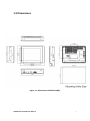
ARCDIS-1XX (TB-6028) 8”, 15.6”, 17”, 18.5”, 21.5” front panel IP65 aluminum die-casting chassis Display User Manual Release Date Revision Jul. 2015 V1.2 ®2015 Aplex Technology, Inc. All Rights Reserved. Published in Taiwan Aplex Technology, Inc. 15F-1, No.186, Jian Yi Road, Zhonghe District, New Taipei City 235, Taiwan Tel: 886-2-82262881 Fax: 886-2-82262883 ARCDIS-1XX (TB-6028) User Manual E-mail: [email protected] URL: www.aplextec.com 0 Revision History Reversion Date Description 1.0 2014/10/03 Official Version 1.1 2015/06/10 Add 15.6”, 17”, and 18.5” 1.2 2015/07/24 Delete description of die-casting, Modify Power Consumption ARCDIS-1XX (TB-6028) User Manual 1 Warning!___________________________ This equipment generates, uses and can radiate radio frequency energy and if not installed and used in accordance with the instructions manual, it may cause interference to radio communications. It has been tested and found to comply with the limits for a Class A computing device pursuant to FCC Rules, which are designed to provide reasonable protection against such interference when operated in a commercial environment. Operation of this equipment in a residential area is likely to cause interference in which case the user at his own expense will be required to take whatever measures may be required to correct the interference. Electric Shock Hazard – Do not operate the machine with its back cover removed. There are dangerous high voltages inside. Disclaimer This information in this document is subject to change without notice. In no event shall Aplex Technology Inc. be liable for damages of any kind, whether incidental or consequential, arising from either the use or misuse of information in this document or in any related materials. ARCDIS-1XX (TB-6028) User Manual 2 Table of Contents Revision History………………………………………………………………………………….1 Warning!………………………………………………………………………………….……..….2 Disclaimer……………………….……………………………………………….…………………2 Chapter 1 Getting Started 1.1 Features…………………………………………………..…………………………….5 1.2 Specifications…………………………………………………………………………5 1.3 Dimensions……………………...……………...…..…………………………….…7 1.4 System Diagram(Full Function)................................................12 1.5 Brief Description of ARCDIS-1XX …………….………..………………….13 1.6 Display Mode…………………………………………..…………………………..19 Chapter 2 OSD 2.1 AD Board OSD Functions………….…...………..….…..……………….….20 2.2 OSD Controls……………………………..…………….…………………….……21 2.3 OSD Functions…………………………………………..………………………...22 2.4 OSD Default Parameter……………..…………….………………………....22 2.5 Main Menu………………………………..…………….……………………......23 Chapter 3 Installation 3.1 Windows 2000/XP/2003/Vista Universal Driver Installation for PenMount 6000 Series…..……………………..………………………...…27 3.2 Installing Software (Resistive Touch Screen Type)…………..…..27 3.3 Software Functions (Resistive Touch Screen Type)………………30 3.4 Installing Software (Projected Capacitive Touch)…….............38 3.5 Software Functions (Projected Capacitive Touch)………….……43 Appendix A: Board Descriptions & Specifications 51 Descriptions…………………………………….………………………………………...51 Specifications…………………………..…………….………………………………....51 Board Dimensions………………….…………………….……………………………52 ARCDIS-1XX (TB-6028) User Manual 3 Appendix B: Panel Mounting and VESA Mounting 53 Figures Figure 1.1: Dimensions of ARCDIS-108(P)………….…………………..…..7 Figure 1.2: Dimensions of ARCDIS-116(P)……………………………………8 Figure 1.3: Dimensions of ARCDIS-117(P)..………………………………...9 Figure 1.4: Dimensions of ARCDIS-118(P)…………………………………10 Figure 1.5: Dimensions of ARCDIS-121(P)…………………………………11 Figure 1.6: System Diagram of ARCDIS-1XX……………………………...12 Figure 1.7: Front View of ARCDIS-108(P)……….………………………….14 Figure 1.8: Rear View of ARCDIS-108(P)……………….…………………..14 Figure 1.9: Front View of ARCDIS-116(P)…………………………………..15 Figure 1.10: Rear View of ARCDIS-116(P)……………………………….…15 Figure 1.11: Front View of ARCDIS-117(P)…………………………………16 Figure 1.12: Rear View of ARCDIS-117(P)………………………….………16 Figure 1.13: Front View of ARCDIS-118(P)…………………………………17 Figure 1.14: Rear View of ARCDIS-118(P)………………………………....17 Figure 1.15: Front View of ARCDIS-121(P)…………………………….….18 Figure 1.16: Rear View of ARCDIS-121(P)………….……………………...18 Figure A: Dimensions of TB-6028……………………………………………..52 Figure B: Panel mounting and VESA mounting………………………….53 ARCDIS-1XX (TB-6028) User Manual 4 Chapter 1 Getting Started 1.1 Features Solid Aluminum chassis Variety of LCD panel size selections Front bezel IP65 VGA and DVI input, RCA is for option 9~36V DC wide range power input 1.2 Specifications ARCDIS-108(P) ARCDIS-116(P) ARCDIS-117(P) ARCDIS-118(P) ARCDIS-121(P) 8” color TFT 15.6”color TFT 17”color TFT 18.5”color TFT 21.5”color TFT LCD LCD LCD LCD LCD Hardware Display Type Default I/O: 1 x 3 pins terminal block power input 9~36V DC 1 x DVI 1 x VGA External I/O Port 1 x USB for Touch control Option I/O: 1 x RCA 1 x RS-232 DB-9 for Resistive Touch control On board controller, extendable key pad from connector OSD Control Transfer Board OSD Membrane Keypad Speaker 1 x 3W AMP internal pin header for option LCD Max. Resolution 800 x 600 1366 x 768 1280 x 1024 1366 x 768 1920 x 1080 Max. Color 16.2M 16.7M 16.7M 16.7M 16.7M Luminance(cd/m²) 350 300 350 300 250 Contrast Ratio 500 : 1 500 : 1 800 : 1 1000 : 1 3000 : 1 Viewing Angle 140°/125° 160°/160° 160°/140° 170°/160° 178°/178° 40,000 hrs 50,000 hrs 50,000 hrs 50,000 30,000 hrs (H/V) Backlight Lifetime ARCDIS-1XX (TB-6028) User Manual 5 9~36V DC on board Power Input MAX: MAX: MAX: MAX: MAX: Power 4.7W(108) 12.3W(116) 14.3W(117) 21.5W(118) 21.7W(121) Consumption MAX: MAX: MAX: MAX: MAX: 3.6W(108P) 12.8W(116P) 18.4W(117P) 20.4W(118P) 24.9W(121P) Touch Screen (ARCDIS-1XX) Type Resistive Touch Window Interface USB / RS-232 Light Transmission Over 80% Touch Screen (ARCDIS-1XXP) Type Projected Capacitive Interface USB Light Transmission Over 90% Mechanical Aluminum chassis Construction Dimensions Net Weight Mounting Aluminum Die-casting chassis only for 8” 231 x 176 x 51 412 x 277.5 x 439 x 348 x 64.8 499.6 x 314.6 x 557 x 362 x 64.8 mm 60.4 mm mm 59.9 mm mm 1.8 kg 4.5 kg 9.56 kg 5.9 kg 7.3 kg Panel / VESA Panel / VESA 100x100 75x75 Environment Specifications Operating 0 ~ 50 ℃ (32 ~ 122 ℉) Temperature -20 ~ 60 ℃ (-4 ~ 140 ℉) Storage Temperature Storage Humidity 10 ~ 90% @40℃ Non-condensing IP Rating Front Panel IP65 Certificate CE/FCC Class A ARCDIS-1XX (TB-6028) User Manual 6 1.3 Dimensions Figure 1.1: Dimensions of ARCDIS-108(P) ARCDIS-1XX (TB-6028) User Manual 7 Figure 1.2: Dimensions of ARCDIS-116(P) ARCDIS-1XX (TB-6028) User Manual 8 Figure 1.3: Dimensions of ARCDIS-117(P) ARCDIS-1XX (TB-6028) User Manual 9 Figure 1.4: Dimensions of ARCDIS-118(P) ARCDIS-1XX (TB-6028) User Manual 10 Figure 1.5: Dimensions of ARCDIS-121(P) ARCDIS-1XX (TB-6028) User Manual 11 1.4 System Diagram (Full Function) Figure 1.6: System diagram of ARCDIS-1xx ARCDIS-1XX (TB-6028) User Manual 12 1.5 Brief Description of ARCDIS-1XX ARCDIS-1XX with TB-6028 AD Board is a total IP65 aluminum front bezel and chassis LCD Display, which comes with 8 inch (luminance of 350 cd/m²), 15.6 inch (luminance of 300 cd/m²), 17 inch (luminance of 350 cd/m²), 18.5 inch (luminance of 300 cd/m²) and 21.5 inch (luminance of 250 cd/m²) TFT LCD. ARCDIS-108(P) comes with a viewing angle of 140 (H) degrees and 125 (V) degrees. ARCDOS-116(P) comes with a viewing angle of 160 (H) degrees and 160 (V) degrees. ARCDIS-117(P) comes with a viewing angle of 160 (H) degrees and 140 (V) degrees. ARCDIS-118(P) comes with a viewing angle of 170(H) degrees and 160 (V) degrees. ARCDIS-121(P) comes with a viewing angle of 178 (H) degrees and 178 (V) degrees. ARCDIS-1XX has more outstanding features, thus giving the best in monitoring and control applications. ARCDIS-108 can be VESA-75 mounted. ARCDIS-116, 117, 118 and ARCDSI-121 can be VESA-100 mounted. ARCDIS-1XX (TB-6028) User Manual 13 Figure 1.7: Front View of ARCDIS-108(P) Figure 1.8: Rear View of ARCDIS-108(P) ARCDIS-1XX (TB-6028) User Manual 14 Figure 1.9: Front View of ARCDIS-116(P) Figure 1.10: Rear View of ARCDIS-116(P) ARCDIS-1XX (TB-6028) User Manual 15 Figure 1.11: Front View of ARCDIS-117(P) Figure 1.12: Rear View of ARCDIS-117(P) ARCDIS-1XX (TB-6028) User Manual 16 Figure 1.13: Front View of ARCDIS-118(P) Figure 1.14: Rear View of ARCDIS-118(P) ARCDIS-1XX (TB-6028) User Manual 17 Figure 1.15: Front View of ARCDIS-121(P) Figure 1.16: Rear View of ARCDIS-121(P) ARCDIS-1XX (TB-6028) User Manual 18 1.6 Display Mode Item Resolution H Freq.(kHz) V Freq.(Hz) Remark 1 640x350@70 31.469 70.087 VGA 2 640x400@70 31.469 70.087 VGA 3* 640x480@60 31.469 59.940 VESA 4 640x480@66 35.000 66.667 MAC 5 640x480@72 37.861 72.809 VESA 6* 640x480@75 37.500 75.000 VESA 7 720x400@70 31.469 75.000 TEXT 8 800x600@56 35.156 56.250 VESA 9* 800x600@60 37.879 60.317 VESA 10 800x600@72 48.077 72.188 VESA 11* 800x600@75 46.875 75.000 VESA 12 832x624@75 49.107 75.087 MAC 13 848x480@60 31.020 60.000 VESA 14* 1024x768@60 48.363 60.004 VESA 15* 1024x768@75 60.023 75.029 VESA 17 1152x864@70 63.850 70.000 VESA 18 1152x864@75 67.500 75.000 VESA 19 1152x900@76 71.809 76.149 SUN 20* 1280x768@60 47.730 60.000 VESA 21* 1280x768@75 60.290 74.890 VESA 22 1280x960@60 60.000 60.000 VESA 23* 1280x1024@60 63.980 60.000 VESA 24* 1280x1024@75 79.976 75.025 VESA 25* 1366x768@60 47.710 60.020 VESA 26 1440x900@60 56.040 60.000 VESA 27 1440x1050@60 65.320 59.980 VESA 28 1440x1050@75 82.280 74.870 VESA 29* 1920x1080@60 67.500 60.000 VESA ARCDIS-1XX (TB-6028) User Manual 19 Chapter 2 OSD 2.1 AD Board OSD Functions Auto Adjust Up/Left Menu/Entry Down/Right Power Power Indicator Power switch: To turn ON or OFF the power Shift the icon to the right side or shift it up Shift the icon to the left side or shift it down Menu: To enter OSD menu for related icon and item. Auto Button: One-touch auto adjustment 1.) Getting into Burn-in Mode Before setting into a burn-in mode, first disconnect the AC power cord. Then press (don’t let them go) the buttons until the AC power cord is connected and the “RGB” appears on the top left corner of your screen. Now it can be put into the burn-in mode for changing colors. 2.) Getting Out of Burn-in Mode Before getting out of the burn-in mode, please first disconnect the AC power cord. Then press the button (If not workable, press the button and don’t let them go) until the AC power cord is connected. Please don’t let your fingers go until the AC power cord is connected again and the wording of “RGB” appears on the top left corner of your screen, and wait for 3 second. Under the non-signal entry situation, if Cable Not Connected is seen, exit is thus successfully made. ARCDIS-1XX (TB-6028) User Manual 20 When the Burn-in Mode is Unable to Eradicate… 1.) If the “RGB” is still on the top left corner of the screen, press “Miscellaneous” and choose “Reset”, and then Yes, and press to enter . When the screen goes black, disconnect power and repeat the above steps. 2.) If the “RGB” is not found, disconnect the AC power cord first. Then press the buttons (don’t let them go) until the AC power cord is connected, and wait for 2 to 3 seconds. When “RGB” appears, repeat the above steps. 2.2 OSD Controls To make any adjustment, select the following: 1. Press (Menu) to show the OSD menu or disable the OSD menu. 2. Select the icon that you wish to adjust with the ( / 3. Press (Menu) and then choose the item with the ( 4. Press (Menu) and then adjust the quality with the ARCDIS-1XX (TB-6028) User Manual or +/-) key in the menu. / ( or +/-) key. / or +/-) key. 21 2.3 OSD Function 1. Power button: Power on/off 2. Down button: Brightness 3. Up button: Volume 4. Menu button: Menu 5. Auto button: Auto adjustment 2.4 OSD Default Parameter ARCDIS-108(P) ARCDIS-116(P) ARCDIS-117(P) ARCDIS-118(P) ARCDIS-121(P) 50 50 50 50 50 50 50 50 50 50 Management H. Position V. Position Pixel Clock Phase auto auto auto auto auto auto auto auto auto auto auto auto auto auto auto auto auto auto auto auto Color Red Green Blue sRGB 50 50 50 sRGB 50 50 50 sRGB 50 50 50 sRGB 50 50 50 sRGB 50 50 50 50 50 7 50 50 7 50 50 7 50 50 7 50 50 7 Luminance Brightness Contrast OSD H. Position V. Position OSD time Language English ARCDIS-1XX (TB-6028) User Manual 22 2.5 Main Menu In the Main menu, there are the following items: Color Image Setting Position OSD Menu Language Misc. Exit For Color, check out the following: Contrast Brightness Color Adjust Color Temp Back ARCDIS-1XX (TB-6028) User Manual 23 For Image setting, check out the following: Clock Phase Gamma Sharpness Back In the Position, there are the following: H. Position V. Position Back ARCDIS-1XX (TB-6028) User Manual 24 In the OSD menu, there are: OSD H. Pos. OSD V. Pos. OSD Timer Back In the Language menu, there are: English Frances Germany Spanish Traditional Chinese Simplified Chinese Japanese ARCDIS-1XX (TB-6028) User Manual 25 In the Misc menu, there are: Signal Source Select VGA: Analogue VGA Input Select DVI: Digital DVI-D Input Select AV: Composite Video Input Select SV: S-Video Video Input Reset Back ARCDIS-1XX (TB-6028) User Manual 26 Chapter 3 Installation 3.1 Windows XP/2003/Vista/7 Universal Driver Installation for PenMount 6000 Series Before installing the Windows XP/2003/Vista/7 driver software, you must have the Windows XP/2003/Vista/7 system installed and running on your computer. You must also have one of the following PenMount 6000 series controller or control boards installed: PM6500, PM6300. 3.2 Installing Software (Resistive Touch Screen Type) If you have an older version of the PenMount Windows XP/2003/Vista/7 driver installed in your system, please remove it first. Follow the steps below to install the PenMount DMC6000 Windows XP/2003/Vista/7 driver. Step 1. Click Next to continue. ARCDIS-1XX (TB-6028) User Manual 27 Step 2. Read the license agreement. Click I Agree to agree the license agreement. Step 3. Choose the folder in which to install PenMount Windows Universal Driver. Click Install to start the installation. ARCDIS-1XX (TB-6028) User Manual 28 Step 4. Wait for installation. Then click Next to continue. Step 5. Click Continue Anyway. ARCDIS-1XX (TB-6028) User Manual 29 Step 6. Click Finish to complete installation. 3.3 Software Functions (Resistive Touch Screen Type) Upon rebooting, the computer automatically finds the new 9036CH5 control board. The touch screen is connected but not calibrated. Follow the procedures below to carry out calibration. 1. After installation, click the PenMount Monitor icon “PM” in the menu bar. 2. When the PenMount Control Panel appears, click “Calibrate”. PenMount Control Panel The functions of the PenMount Control Panel are Calibrate, Multiple Monitors, Tools, and About, which are explained in the following sections. Device In this window, you can find out that how many devices are detected on your system. ARCDIS-1XX (TB-6028) User Manual 30 Calibrate This function offers two ways to calibrate your touch screen. “Standard Calibration” adjusts most touch screens. “Advanced Calibration” adjusts aging touch screens. Standard Calibration Click this button and arrows appear pointing to red squares. Use your finger or stylus to touch the red squares in sequence. After the fifth red point calibration is complete. To skip, press “ESC”. Advanced Calibration Advanced Calibration uses 4, 9, 16 or 25 points to effectively calibrate touch panel linearity of aged touch screens. Click this button and touch the red squares in sequence with a stylus. To skip, press “ESC”. Standard Calibration Step 1. Please select a device then click “Configure”. You can also double click the device too. ARCDIS-1XX (TB-6028) User Manual 31 Step 2. Click Standard Calibration NOTE: The older the touch screen is, the more Advanced Mode calibration points you need for an accurate calibration. Use a stylus during Advanced Calibration for greater accuracy. ARCDIS-1XX (TB-6028) User Manual 32 Advanced Calibration – click Advanced Calibration Plot Calibration Data Check this function and a touch panel linearity comparison graph appears when you have finished Advanced Calibration. The blue lines show linearity before calibration and black lines show linearity after calibration. Multiple Monitors Multiple Monitors support from two to six touch screen displays for one system. The PenMount drivers for Windows XP/2003/Vista/7 support Multiple Monitors. This function supports from two to six touch screen displays for one system. Each monitor requires its own PenMount touch screen control board, either installed inside the display or in a central unit. The PenMount control boards must be connected to the computer COM ports via the RS-232 interface. Driver installation procedures are the same as for a single monitor. Multiple Monitors support the following modes: ARCDIS-1XX (TB-6028) User Manual 33 Windows Extends Monitor Function Matrox DualHead Multi-Screen Function nVidia nView Function NOTE: The Multiple Monitor function is for use with multiple displays only. Do not use this function if you have only one touch screen display. Please note once you turn on this function the rotating function is disabled. Enable the multiple display function as follows: 1. Check the Multiple Monitor Support box; then click Map Touch Screens to assign touch controllers to displays. 2. When the mapping screen message appears, click OK. 3. Touch each screen as it displays “Please touch this monitor”. Following this sequence and touching each screen is called mapping the touch screens. ARCDIS-1XX (TB-6028) User Manual 34 4. Touching all screens completes the mapping and the desktop reappears on the monitors. 5. Select a display and execute the “Calibration” function. A message to start calibration appears. Click OK. NOTES: 1. If you use a single VGA output for multiple monitors, please do not use the Multiple Monitor function. Just follow the regular procedure for calibration on each of your desktop monitors. 2. The Rotating function is disabled if you use the Multiple monitor function. 3. If you change the resolution of display or screen address, you have to redo Map Touch Screens, so the system understands where the displays are. Tools Draw Tests or demonstrates the PenMount touch screen operation. Right Button Icon Enable right button function. The icon can show on Desktop or System Tray (menu bar). ARCDIS-1XX (TB-6028) User Manual 35 About This panel displays information about the PenMount controller and this driver version. PenMount Monitor Menu Icon The PenMount monitor icon (PM) appears in the menu bar of Windows XP/2003/Vista/7 system when you turn on the PenMount Monitor in the PenMount Utilities. The PenMount Monitor has the following functions: ARCDIS-1XX (TB-6028) User Manual 36 Control Panel Open Control Panel Windows Beep Setting Beep function for each device Right Button When you select this function, a mouse icon appears in the right-bottom of the screen. Click this icon to switch between Right and Left Button functions. Exit Exits the PenMount Monitor function. Configuring the Rotation Function 1. Install the rotation software package. 2. Choose the rotating function (0°, 90°, 180°, 270°) in the 3rd party software. The calibration screen appears automatically. Touch this point and rotation is mapped. NOTE: The rotating function is disabled if you use Monitor Mapping ARCDIS-1XX (TB-6028) User Manual 37 3.4 Installing Software (Projected Capacitive Touch) Step 1. Insert Driver CD, the screen below would appear. Click Next to continue. Step 2. Select I accept the terms of the license agreement. Click Next. ARCDIS-1XX (TB-6028) User Manual 38 Step 3. Click Install RS232 interface driver, then click Next to continue. Step 4. Select None. Click Next. Step 5. Click OK. ARCDIS-1XX (TB-6028) User Manual 39 Step 6. Click Support Muti-Monitor System. Click Next. Step 7. Go to C:\Program Files\eGalaxTouch. Click Next. ARCDIS-1XX (TB-6028) User Manual 40 Step 8. Click Next. Step 9. Tick Create a eGalaxTouch Utility shortcut on desktop. Click Next. ARCDIS-1XX (TB-6028) User Manual 41 Step 10. Wait for installation. Step 11. Click Yes to do 4 point calibration. ARCDIS-1XX (TB-6028) User Manual 42 3.5 Software Functions (Projected Capacitive Touch) General In this window, you can see there is USB Controller. Click OK to continue. Monitor Mapping to adjust touch panel Add to search for device ARCDIS-1XX (TB-6028) User Manual 43 Setting Beep Beep On Touch Beep On Release Beep From System Beep Beep From Sound Card Linearization Style 9 points 25 points Double Click Time Shorter Longer Double Click Area Smaller Bigger Normal mode Simulate the mouse mode ARCDIS-1XX (TB-6028) User Manual 44 Option Function Enable Constant Touch Enable Auto Right Click Enable Touch Enable Cursor Stabilization Constant Touch Area Auto Right Click Time ARCDIS-1XX (TB-6028) User Manual 45 Tools Click OK to continue the settings. 4 Points Calibration Do 4 points alignment to match display. Clear and Calibrate Clear linearization parameter and do 4 points alignment. Linearization Do 9 points linearization for better touchscreen linearity. Draw Test Do draw test to verify the touch accuracy. ARCDIS-1XX (TB-6028) User Manual 46 Display In this window, it shows the mode of display. Enable Multiple Monitors. Map to main display if system has only one display monitor Full Screen Lower Screen Left Screen Upper Screen Right Screen ARCDIS-1XX (TB-6028) User Manual 47 Other Other mode of display. Quarter1~4 and Customized area. Active Area Drag active area to enable Active Area Function. ARCDIS-1XX (TB-6028) User Manual 48 Hardware Saturn Hardware Configuration ARCDIS-1XX (TB-6028) User Manual 49 About To display information about eGalaxTouch and its version. ARCDIS-1XX (TB-6028) User Manual 50 Appendix A: Board Descriptions & Specifications Descriptions Model TB-6028 Function Descriptions AD board,VGA /DVI-D/RCA input,LVDS output TB-6028TU AD board,VGA /DVI-D/RCA input,LVDS output,USB/Touch controller TB-6028TR AD board,VGA /DVI-D/RCA input,LVDS output,RS232/Touch controller TB-6028TRS AD board, VGA/DVI-D input, LVDS output, RE232/Touch controller Specifications Specifications Board Size 170 x 113 x 1.6 mm Chipset Realtek RTD2533VH PenMount 6000 Input 1 x VGA input Port 1 x DB15 connector(Default) 1 x 1*12Pin Wafer (option) 1 x DVI-D input 1 x RCA input(option) 1 x RS232 input port, DB9 connector (option) 1 x USB 2.0 input port, Single USB connector (option) 1 x Line in port, Phone Jack (option) 1 x 3-pin power input connector (Wide range DC+9V~36V) 1 x OSD function support 1 x Touch controller(option) Output 1 x 24bit Dual Channel LVDS output interface 1 x Audio Power Amplifier (Line out, option) 1 x USB 2.0 Port(option) Resolution Up to 1920 x1200 for LVDS Power input DC9V-36V Temperature Operating: -20℃ to 70℃ Storage: -40℃ to 85℃ Humidity 0% - 80%, non-condensing, operating EMI/EMS Meet CE/FCC class A ARCDIS-1XX (TB-6028) User Manual 51 Board Dimensions (units :mm) Figure A: Dimensions of TB-6028 ARCDIS-1XX (TB-6028) User Manual 52 Appendix B: Panel Mounting and VESA Mounting The ARCDIS-1XX is designed to be panel-mounted and VESA mounted as shown in Picture. Just carefully place the unit through the hole and tighten the given screws from the rear to secure the mounting. Figure B: Panel mounting and VESA mounting *Notice: Tighten the mounting clip screws by hand until the gasket seal contacts the mounting surface uniformly. Tighten the mounting clips screws to a torque of 8 ~ 10 kgf-cm by using the specified sequence, making sure not to overtighten. *Tighten the mounting clips to the specified torque to provide a proper seal and to prevent damage to the product. Aplex assumes no responsibility for water or chemical damage to the product or other equipment within the enclosure due to improper installation. ARCDIS-1XX (TB-6028) User Manual 53