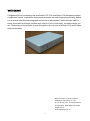
1
Installation and User Guide avaControl-100 WELCOME Congratulations on purchasing the avaControl-100. The avaControl-100 integrates multiple complicated control, automation and internet protocols into one simple plug-and-play device. It is a central controller that integrated and control of all wireless Z-wave devices used for home automation and keeps connect and control of your home easily, no matter where you are. Please take a few minutes to read this guide to set up your avaControl-100 and Z-wave network smoothly. Manual version V1.00 25-12-2014 Avadesign Technology Co. Ltd. 4F.-10, No.351, Sec. 2, Zhongshan Rd., Zhonghe Dist., New Taipei City 23504, Taiwan R.O.C. www.avadesign.com.tw 1 Table of Contents Chapter 1 Introduction . . . . . . . . . . . . . . . . . . . . . . . . . . . . . .. . . . . . . . . . . . . . . . . . . . . . . . . 4 1.1 Benefits . . . . . . . . . . .. . . . . . . . . . . . . . . . . . . . . . . . . . .. . . . . . . . . . . . . . . . . . . . . . . . .. . . 4 1.2 Key Features . . . . . . . . . . . . . . . . . . . . . . . . . . . . . . . . . . . .. . . . . . . . . . . . . . . . . . . . . . . . . 1.3 Technical Specifications . . . . . . . . . . . . . . . . . . . . . . . . . . . .. . . . . . . . . . . . . . . . . . . . . . . . . 1.4 Hardware Overview. . . . . . . . . . . . . . . . . .. . . . . . . . . . . . . .. . . . . . . . . . . . . . . . . . . . . . . . . 1.4.1 Front Panel and LED Indicator . . . . . .. . . . . . . . . . . . . .. . . . . . . . . . . . . . . . . . . . . . . . . 1.4.2 Back Panel . . . . . .. . . . . . . .. . . . . . . . . . . . .. . . . . . . .. . . . . . . . . . . . . . . . . . . . . . . . . 5 5 6 6 7 Chapter 2 Quick Install. . . . . . . . . . . . . . . . . . . . . . . . . . . . . . . . . . . . . . . . . . . . . . . . . . . . 8 2.1 Unpacking . . . . . . . . . . . . . . . . . . . . . . . . . . . . . . .. . . . . . . . . . .. . . . . . . . . . . . . . . . . . . . . . . . . . .8 2.2 The Procedure of Connection . . . . . . . . . . . . . . . . . . . . . . . . . . . . . . . . . . . . . . . . . . . . . . . . . . . . . . . .8 2.3 Find the IP address of your avaControl-100 . . . . . . . . . . . . . . . . . . . . . . . . . . . . . . . . . .. . . . .. . . . .10 2.4 Initial setup procedure for avaControl-100 web configuration . . . . . . . . . . . . . . . . . . . .. . . .. . . . .10 Chapter 3 Full web configurations . . . . . . . . . . . . . . . . . . . . . . . . .. . . . . . . . . . . . .. . . . . . . .11 3.1 Enter web configure page . . . . . . . . . . . . . . . . . . . . . . . . . . . . . . . . . . . . . . . . . . . . . . . . . . . . 11 3.2 SetZwave – Z-Wave device settings . . . . . . . . . . . . . . . . . . . . . . . . . . . . . . . . . . . . . . . . . . . 12 3.2.1 The Z-Wave device configuration . . . . . . . . . . . . . . . . . . . . . . . . . . . . . . . . . . . . . . . . . . 12 3.2.1.1 Add a Z-Wave device . . . . . . . . . . . . . . . . . . . . . . . . . . . . . . . . . . . . . . . . . . . . . 12 3.2.1.2 Remove a Z-Wave device 3.2.2 Z-Wave Control and Log . . . . . . . . . . . . . . . . . . . . . . . . . . . . . . . . . . . . . . . . . . 14 . . . . . . . . . . . . . . . . . . . . . . . . . . . . . . .. . . . . . . . . . . . . . . . . 16 3.2.3 Topology . . . . . . . . . . . . . . . . . . . . . . . . . . . . . . . . .. . . . . . . . . . . . . . . . . . . .. . . . . . . . 17 3.2.4 Door Lock Security . . . . . . . .. . . . . . . . . . . . . . . . . . . . . . . . . . . . . . . . . . . . . . . . . . . . . 18 3.2.5 Version Information . . . . . . . . . . . . . . . . . . . . . . . . . . 3.3 Room Setting . . . . . . . . . . . . . . . . . . . . . . . . . . . . . . . . . . . . . . . . . . . . . . . . . 19 . . . . . . . . . . . . . . . . . . . . . . . . . . . . . . . . . . . . . 20 3.3.1 Create Room . . . . . .. . . . . . . . . . . . . . . . . . . . . . . . . . . . . . . . . . 3.3.2 All Rooms . . . . . . . . . . . . . . . . . . . . . . . . . . . . . . . . . . . . . . . . 20 . . . . . . . . . . . . . . . . . . . . . . . . . . . . . . . . . . . . 21 3.4 Device Setting . . . . . . . . . . . . . . . . . . . . . . . . . . . . . . . . . . . . . . . . . . . . . . . . . . . . . . . . . . . 22 3.5 Scene Setting . . . . . . . . . . . . . . . . . . . . . . . . . . . . . . . . . . . . . . . . . . . . . . . . . . . . . . . . . . . 26 3.5.1 Create Scene . . . . . . . . . . . . . . . . . . . . . . . . . . . . . . . . . . . . . . . . . . . . . . . . . . . . . . . . . . . . . . . 26 3.5.2 All Scenes . . . . . . . . . . . . . . . . . . . . . . . . . . . . . . . . . . . . . . .. . . . . . . . . . . . . . . . . . . . .. . . . . . 28 3.6 Trigger – Monitor the Z-Wave Devices . . . . . . . . . . . . . . . . . . . . . . ... . . . . . . . . . . . . . . . . . . . . 29 3.6.1 Create Trigger. . . . . . . . . . . . . . . . . . . . . . . . . . . . . . . . . . . . . . .. . . . . . . . . . . . . . . . . . 29 2 3.7 Schedule – Arrangement for Z-Wave Devices on Schedule . . . . . . . . . . . . . . . . . . . . . . . . . . . 30 3.7.1 Create Schedule . . . . . . . . . . . . . . . . . . . . .. . . . . . . . . . . . . . . . . . . . . . . . . . . . . . . . . . . 30 3.8 Report . . . . . . . . . . . . . . . . . . . . . . . . . . . . . . . . . . . . . . . . . . . . . . . . . . . . . . . . . . . . . . . . . . 31 3.9 Camera . . . . . . . . . . . . . . . . . . . . . . . . . . . . . . . . . . . . . . . . . . . . . . . . . . . . . .. . . . . . . . 33 3.9.1 Camera Setting . . . . . . . . . . . . . . . . . . . . . . . . . . . . . . 3.9.2 Camera View 3.10 Help . . . . . . . . . . . . . . . . . . . . . . . . 33 ..................................... . . . . . . . . . . . . . . . . . 34 . . . . . . . . . . . . . . . . . . . . . . . . . . . . . . . . . . . . . . . . . . . . . . . . . . . . . . . . . . . . . . . . 35 3 Chapter 1 Introduction Avacontrol-100 is a central controller that integrated and control of all wireless Z-wave devices used for home automation. It also provides Gateway to connect to Internet. Through Internet you can see all kinds of devices status of your home at any time and any place via your smartphone. You can control the home devices such as lighting, air conditioning, door lock and unlock, you can also receive the alarm message of your home. Energy usage monitors of your home at any time is real-time recording to the cloud host, home alarm messages are immediately delivered to the cloud message monitoring center for the necessary treatment. The Avacontrol-100 controls switches, dimmers, motion sensors, temperature sensors and so on many Z-Wave devices. Avacontrol-100 integrates complicated control, automation and internet protocols into one simple plug-and-play device. It provides an interface that allows you to manage your home easily, whether you are at home or not. 1.1 Benefits No ongoing cost Secure, remote access over the internet is FREE for all users. Send unlimited notification emails without any pay! For sending free text messages to your mobile phone is through Push notification. Compatibility with all Z-Wave devices Includes deadbolt locks, scene controllers, sensors, lighting controls, thermostats, energy usage monitors, and even more, Avadesign lets you take advantage of everything that Z-Wave offers, with the ability to add IP cameras, alarm panels, IR devices and so on. Powerful applications Avacontrol APP extends your experience, such as weather forecasting, media control, alarm panel integration, remote live video streaming, etc. Energy monitoring Avacontrol advanced energy metering capabilities empower you to take control of your electricity bill and start to save money. Security surveillance and video monitoring You can stream live video from plug and play IP cameras to your smartphone now! You can also store video footage on secure servers that you can access from anywhere, anytime. Open API Avacontrol-100 allows you or your developers to create new Apps to offer to all other Avacontrol’s users. 4 No Internet Connection Required! Even without internet access, Avacontrol can set-up and configure your wired or Wi-Fi wireless network, allowing you to control all your devices locally. 1.2 Key Features Provide one WAN port and four LAN port Router function Provide two USB Host port, you can connect Z-Wave USB Dongle and 3G USB Ethernet card Provide compatible Z-Wave Plus communication protocol that connects all kinds of Z-Wave devices that includes window sensors, electric locks, lighting dimmer controls, energy usage monitor, air quality detector, temperature and humidity sensors, fire safety sensors. Provide a service platform to connect to the cloud service. Provide IP-Cam viewing interface Provide high level application program development tool interface (HTTP / CGI interface API). System integrators can develop their own unique user interface APP. Provide free download APP. 1.3 Technical Specifications Technical Specifications Hardware Specifications CPU CKVIUM ECONA CNS3410, 600MHZ RAM 128MB Flash ROM 32MB OS Linux 2.6.31 USB Port USB Host 2.0 x2 Ethernet port RJ-45 10/100Mb , support 1 WAN + 4 LAN Physical and Environmental Characteristics Dimensions 155(W) x 106(H) x 29(D) mm Weight 300g Operating Temp: 0°C~45°C (32°F~113°F) Temp. & Humidity: 10% ~ 90% relative humidity, non-condensing Humidity INPUT: AC100V~240V, 50/60Hz Power Adaptor OUTPUT: DC 12V, 2.0A outer casing Plastic Approvals FC、CE、RoHS Made in Taiwan Country of origin 5 Avacontrol-100 main unit x 1 pcs Packing Accessories AC to DC+12V Power adapter x 1 pcs Z-WAVE USB Dongle (ZU1401US) USB adapter One RJ-45 cable Software Specifications Protocol Z-Wave HA Functions Sense Control Lighting Control Door Lock Control Sensor Trigger Even Schedule setting Support mobile phone Push Notification Support Devices Place Location User account Management (admin and normal user) Support Remote update software Z-Wave Capacity Support 100 Z-Wave notes 1.4 Hardware Overview 1.4.1 Front Panel and LED Indicator avaControl RESET Z WAN LAN 4 3 2 1 PWR 1 RESET: If avaControl-100 encounters any system crash, you may press this button to reload factory default value as press the button over 3 seconds or reset back to latest configuration file while pushing the button. Z : When the LED flash slowly, avaControl-100 boot successfully. : When the LED flash slowly, avaControl-100 connects to Avadesign cloud server successfully. LAN: avaControl-100 provides four RJ45 type LAN ports connecting to your computer or network device such as Hub/Switch via RJ45 cable. Light on means link 100 Mbps. Flash when data is transmitting or receiving with 100 Mbps. Light off means disconnected or undetected. WAN: avaControl-100 provides one RJ45 type WAN port connecting to broadband transmission equipment such as ADSL or Fiber or CABLE Modem via RJ45 cable. Light on means link 100 Mbps. Flash when data is transmitting or receiving with 100 6 Mbps. Light off means disconnected or undetected. PWR: Light on when avaControl-100 is powered by on. 1.4.2 Back Panel 1 2 I O POWER DC+12V WAN1 LAN1 LAN2 LAN3 LAN4 USB POWER: A switch for power on or off DC 12V/2A: Connecting to AC adapter. Input AC 100V~240V, 50/60Hz; Output DC12V 2.0A LAN/WAN: RJ-45 socket, complied with Ethernet 10/100base-T. USB: USB 2.0 ports, USB Type A. 7 Chapter 2 Quick Install After you’ve created your Z-Wave network, you’ll need to install your AvaContorl-100. Follow these steps: 2.1 Unpacking Open the carton and unpack the items. Your package should include: Avacontrol-100 main unit x 1 pcs AC to DC+12V Power adapter x 1 pcs Z-WAVE USB Dongle (ZU1401US) USB adapter One RJ-45 cable Avacontrol-100 USB Dongle AC/DC adapter USB adapter RJ-45 cable If items are missing or damaged, notify your Avadesign representative. Keep the carton and packing material. 2.2 The Procedure of Connection Step 1: Plug in DC power adapter to avaControl-100. Step 2: Connect the Ethernet cable to your AvaContorl-100 WAN port and to a network port of your internet router. WAN port Ethernet cable Step 3: Connect the Z-Wave Dongle to USB adapter then connect to the USB port of your avaContorl-100. 8 The step 2 and step 3 have finished as above picture. Step 4: Plug in AC power cord to power source. Step 5: avaControl-100 begins the boot process. Step 6: Check the earth icon flash is ready to use. LED in the front panel of avaControl-100 flash or not, Flash is ready to use AvaControl-100 provides three kinds of operational platforms, Web page, Android and iOS, for users. Therefore user can configure the avaControl-100 by his/her PC or smart phone or tablet. The web configuration guide is available in this manual. The installation guide for smart phone/tablet with Android system or iOS system, please refer to other document. 9 2.3 Find the IP address of your avaControl-100 Please download the Java program file named avaControlFinderJava from the website of Avadesign Co., Ltd. http://www.avadesign.com.tw/support/support.html to your PC. Decompress the file and click it twice by left button of your mouse. Then you will see the IP address listing of all of your avaControl-100 as right side. avaControl Finder 2.4 Initial setup procedure for avaControl-100 web configuration In order to set proper functions for each Z-Wave device, you can follow this flow chart before you start to configure avaControl-100. START Add the Z-wave device Function Name in the top menu SetZwave Please refer to section 3.2 Create Room Room Please refer to section 3.3 Create Scene Scene Please refer to section 3.5 Create Trigger Trigger Please refer to section 3.6 Setup Schedule Schedule Please refer to section 3.7 Report 10 Report Please refer to section 3.8 Chapter 3 Full web configurations 3.1 Enter web configure page Move the cursor to the IP address of avaControl-100 on the screen and click it that as shown the diagram of avaControl Finder at section 2.3. Then you will enter the web page for configuration as follows. Please input user name and password. Cancel Login Please input with username: admin and password: admin then click “Login” button on the screen. After login avaControl-100, you will see the home page as shown below. Language selection: English, Traditional Chinese, Simplified Chinese This message indicates there is new version of configuration software for you. You can click the “Update” button to update your software. At right side of home page, you can see the national flag of different country for different language selection. Just click the national flag you will get which language you want. You also can see the orange color button with characters of update. Click “Update” button to update your configuration software. Finished the update procedure, you will see the screen as shown below. A message of “This is the newest version” displays on the screen now. 11 Home Page After Login avaControl-100 user will see screen as above, and there are ten main categories, user can click on each category to extend detail items. Home Room Device Camera Scene Trigger Schedule SetZwave Report Help The various configuration menus are explained below. You can select various function listed in the first line of Home page display. 3.2 SetZwave - Z-Wave device settings One of main functions of avaControl-100 is control and monitoring the room. If you would like to implementation of these efforts require the help of Z-Wave devices in order to complete the task. At first, you need to add the new Z-Wave devices to avaControl-100 for control and monitoring the room or remove the Z-wave device which not used. 3.2.1 The Z-Wave device configuration 3.2.1.1 Add a Z-Wave device You can add the Z-Wave device by clicking on the category of “SetZwave” in the menu bar. The procedure of adding the Z-wave device is described as follows. Step 1: Enter the "SetZwave" page and select "Device Configuration" 12 Step 1a: Click on “SetZwave” category of main menu. SetZwave-Device Configuration Step 2: Click on “Include New Device” button. Step 1b: Click on “Device Configuration” item. Step 2: Click on the "Include New Device", the screen will appear "Add Device: Waiting for a user action." Step 3: Press the programming switch button on the Z-Wave device for connection. The location of programming switch button depends on the type of Z-Wave device that you use. Please refer to the user manual of the Z-Wave device. Step 3: Press the programming switch button on the Z-wave device. The Z-wave device was added successfully. Plug-in on/off module 13 p.s. You also can buy these Z-Wave devices such as Plug-in on/off module, Door sensor, PIR sensor, Wireless siren…etc. from Avadesign Technology. Step 4: When your Z-Wave device has added successfully, the message of "Add Device: Command has completed successfully" will display on the screen. Step 5: When the new Z-Wave device was found, you can modify the name and room settings as shown below. Step 6: Then click "device", the new Z-wave device is ready to use now. 3.2.1.2 Remove a Z-Wave device You also can remove the Z-Wave device by clicking on the category of “SetZwave” in the menu bar. The procedure of removing the Z-wave device is described as follows. Step 1: Enter the "SetZwave" page and select "Device Configuration" 14 SetZwave-Device Configuration Step 1a: Click on “SetZwave” category of main menu. Step 2: Click on “Exclude Device” button. Step 1b: Click on “Device Configuration” item. Step 2: Click on the "Exclude Device", the screen will appear "Remove Device: Waiting for a user action." Step 3: Press the programming switch button on the Z-Wave device for removing. The location of programming switch button depends on the type of Z-Wave device that you use. Please refer to the user manual of the Z-Wave device. Step 3: Press the programming switch button on the Z-wave device. Plug-in on/off module The Z-wave device was removed successfully. 15 Step 4: When your Z-Wave device has removed successfully, the message of "Remove Device: Command has completed successfully" will display on the screen. 3.2.2 Z-Wave Control and Log AvaControl-100 provides alarm records of all Z-Wave control devices for user as follows. SetZwave-ZwaveControl & Log When you click on “Update” button, you will see the listing of software version updated. Clicking on the “Version” button at the end of screen, the system will check the software version of avaControl-100 for you automatically. Click on “Version” button to check the version. You also can click the “reset” button to reset the system. 16 You can click the “Update” button to download the newest version for updating. You also can click the “reset” button to reset the system shown as above diagram. Then you can click on “OK” button to reset the system or “Cancel” button to quit the reset process. 3.2.3 Topology The topology diagram shows the connection relationship of avaControl-100 and all of Z-wave devices. The small square at row 1 and column 1 represents the avaControl-100. The small square at row 1 and column 2 represents a Z-Wave device. Applying the topology diagram, user can decide the control path of avaControl-100 and each Z-Wave device. For example, the avaControl-100 can control the remote device B indirectly by device A. SetZwave-Topology B A 17 3.2.4 Door Lock Security You can select a door lock to add password or modify password. SetZwave-Door Lock Security Select a door lock to add or modify password. Then you will see the listing of user name and password. Clicking on the pen icon to modify the password. You also can click on the X symbol to delete the password. You can click on the “Add” button to add new password as below. The maximum length of password is 10 digits and you can input numeric 0 ~ 9. 18 You can click on the “Log” button to get the door lock records as below. The maximum number of logs is 5. Please input the record number that equal or less than 5 then click on “Search” button. The “Time” button on the right side of screen is used for time setting by manually. You have to input the right date and time by yourself. When you replace the battery of Electric Deadbolt, please remember to modify the date and time here. 3.2.5 Version Information Clicking on “Version Information” item, you will get the information of software version. SetZwave-Version Information 19 3.3 Room setting AvaControl-100 can classify and integrate all kinds of Z-Wave devices to do home automation includes room, scene, trigger, schedule and report. 3.3.1 Create room Create rooms to distribute Z-Wave devices According to the different room in the family, you can distribute the Z-Wave devices to each room. And you can learn which room was invaded or controlled household appliances quickly. Now, you can create a new room by clicking on “Create Room” item. Then input the room name and click on “Add” button. Room-Create Room Please input the room name. Then click on “Add” button to create a new room. You also can change the icon of the room by clicking on “Change ICON” button. Then you will see some pictures that you can choose for the proper room as below screen. 20 Bathroom Bedroom Kitchen Study room Living room or Meeting room Dining room Hallway If you change icon and input “meeting room” in the field of room name, and click on “Add” button. Then you will see the meeting room appear on the left side of screen. Congratulation! You have created a meeting room successfully. 21 3.3.2 All rooms You can see the device status in each room easily by clicking on “All rooms” item. 3.4 Device setting You can place the Z-wave device in the right room by selecting device function in the top menu and choosing a device which you want. For example, you create a meeting room at section 3.3, and you would like to place light device in this room. The setting procedure is described as following: Step 1: Select “Device” function and clicking on “All Devices” item to show all of the Z-Wave devices on the screen. Step 2: Choose the device that you need and click on the icon of pen to edit the content of device. For example, you place light device in this room. Please refer to the following screen. 22 Device-All Devices Step 1 Step 2: Edit 23 Step 3: Edit the content of light device. Please input the device name and room name. Then click on “Save” button to save the configuration. You also can check this node by clicking on “Check and Remove” button and the message of “The node is OK” displays on the screen. Step 4: Go back to “Room” function and click on “Meeting room” item, then you will see the light device Room-Meeting room Now, you can place another device to other room continuously. For example, you want to place electronic deadbolt in hallway. Please refer to the following screens. 24 Then you will find the electronic deadbolt in hallway now. 25 3.5 Scene Setting - Control Z-Wave devices You can control and combine a number of Z-Wave devices together and execute a designed operation action by clicking one key only. 3.5.1 Create Scene Step 1: Select "Scene" function in the top menu on the screen. Then click on “Create Scene” item. Please input the scene name and click on “Add” button. Scene-Create Scene Step 2: Now, you can see the scene was created and named as “Turn on the light for meeting room”. You also can edit the scene name by clicking on the icon of pen. You also can edit the scene name by clicking on the icon of pen. 26 Then add controlled Z-Wave devices in this scenario that shown as below. For example: you add a switch of light in this scenario. Add a new device Scrolling menu You can add more controlled Z-Wave devices in this scenario by selecting one device in the scrolling menu and clicking on the icon of plus sign on the screen. Then you will see a new controlled device display on the screen now. Delete a controlled Z-Wave device in this scenario by clicking on the icon of “X”. You also can delete a controlled Z-Wave device in this scenario by clicking on the icon of “X”. Then you will see this controlled device disappear on the screen now. Step 3: Setting the proper action for each device. For example: you can turn on the light by clicking on “On” button. Then you will see the color of light has changed to bright yellow. 27 Step 4: You can click on “Run” button of the scene that has set by yourself. The corresponding Z-Wave device will be used. 3.5.2 All Scenes You can see all of scenes by clicking on “All Scenes” item and select the scene that you want to execute. 28 3.6 Trigger - Monitor the Z-Wave devices 3.6.1 Create Trigger The trigger function is used to monitor the setting of Z-wave devices, when an alarm is triggered to launch. Please refer to the following diagram for alarm setting. Trigger-Create Trigger You also can combine both of trigger and scene functions setting. For example: when people enter the meeting room, the light will be turn on automatically. Input the trigger situation and select a scene by clicking on the scrolling menu. 29 Then press the “Save” button. You will see the screen as below. A new trigger is created and displays on You also can modify the trigger and the left of screen. mode by clicking on “Modify” button. 3.7 Schedule – Arrangement for Z-Wave devices on schedule 3.7.1 Create Schedule You can set up a schedule to monitor the security of your home regularly. For example: When nobody at home on Saturday set up to open the Z-Wave device automatically for monitoring. Please click the check square of every week and select the day and time from the scrolling bar. And select the scene that you wanted and input the name of schedule. Then click on “Save” button to save the configuration of schedule. 30 Schedule-Create Schedule Now you will find a new schedule of “alert on Saturday” is created and displayed on the screen. You can decide whether the alarm active You also can modify the schedule or not by clicking on the check square. name by clicking on “Modify” button. 3.8 Report You can get the power consumption of the Z-Wave device by using the report function. This function requires purchase the Smart Energy Switch device to monitor the amount of current. You can see how much power was used at which time period as shown below. Step 1: At first, select a device and unit. Then input time period. 31 Report Step 2: Click on “Search” button. Please waiting for few seconds, then the result is displayed on the screen. Amount of electricity consumption 32 3.9 Camera You can connect and control all of cameras in the house by the function of camera. 3.9.1 Camera Setting You can add a camera by clicking on the icon of “+” or remove a camera by clicking on the icon of “X” or edit and modify the configuration of camera by clicking on the icon of pen as shown below. Camera – Camera Setting Add a camera Edit and modify the configuration of camera Remove a camera Add a Camera Please input the camera name, IP address of camera, camera port, camera URL, MJPG URL, camera account and password. Then click on “OK” button to save the configuration. You also can edit and modify the configuration of camera as shown below. 33 Edit and Modify 3.9.2 Camera View You can view the real-time image by clicking on “Camera View” or the camera name. 34 3.10 Help The function of help in the top menu on the screen will assist you to understand how to set up and use the avaControl-100 by hyperlink to Avadesign company web page to download those documents that you need. 35