1
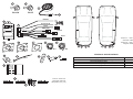
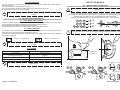
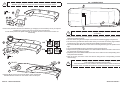
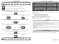
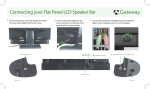
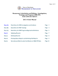
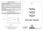
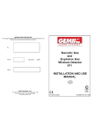
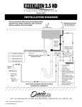
INSTALLATION CERTIFICATE
The undersigned qualified installer attests to have personally fitted the here described system following the
manufacturer instructions.
By :
KIT Parking
Sensor 814
Type of product :
Sold on :
814
.................................................................
INSTALLATION AND
USE MANUAL
Car :
..........................................................................................................................
UK
GEMINI Technologies S.p.A.
Via Luigi Galvani 12 - 21020 Bodio Lomnago (VA) - Italia
Tel. +39 0332 943211 - Fax +39 0332 948080
Web site: www.gemini-alarm.com
Reg. n.532-A
UNI EN ISO 9001:2008
AC 2745/UK Rev. 02 - 10/11
1
2
3
2x
BLACK
2x
BLUE
15
3
5
BROWN
4
BLACK-BLUE
5
13
MAIN UNIT
R
MUTE
GREY-RED
BLACK
20
24
BLUE
7
6a
6
Sensor 1: rear with
shortest cable.
Sensor 4: rear with
longest cable.
9
8
1
12
10 x
4x
PR
3M IMER
429
8UV
11
13
14
4
3
2
1
13
How to remove a
terminal with the
adequate tool (13).
13
TECHNICAL SPECIFICATIONS
Supply voltage
15
13
4
4x
4x
10
3
4x
4x
4x
2
From 9 to 30 Vdc
Current consumption when system running
350mA max.
Service temperature range
From -30°C to +70°C
Ultrasound frequency
40Khz
Software version reference (reported on control unit)
SW04
UK
USER MANUAL
CONTENTS
1.0 - PRELIMINARY ADVICE............................................................................................. PAGE 02
2.0 - WARRANTY CONDITIONS....................................................................................... PAGE 02
USER MANUAL
3.0 - SYSTEM OPERATION..............................................................................................
3.1 - Detection Zones......................................................................................................
3.2 - Rear sensors...........................................................................................................
4.0 - TROUBLESHOOTING GUIDE...................................................................................
4.1 - Low power supply signal..........................................................................................
4.2 - Faulty sensors.........................................................................................................
4.3 - Others......................................................................................................................
.
PAGE 03
PAGE 03
PAGE 04
PAGE 04
PAGE 04
PAGE 04
PAGE 04
INSTALLER MANUAL
5.0 - INSTALLATION OF SENSORS.................................................................................. PAGE 05
6.0 - CONNECTIONS......................................................................................................... PAGE 07
7.0 - PROGRAMMING....................................................................................................... PAGE 08
8.0 - SETTING OF PARAMETERS.................................................................................... PAGE 09
9.0 - TESTING................................................................................................................... PAGE 09
10.0 - WASTE ELECTRICAL AND ELECTRONIC EQUIPMENT (WEEE) DIRECTIVE.... PAGE 09
1.0 - PRELIMINARY ADVICE
Dear customer,
Before installing, identify your kit and refer to it for the correct instructions.
The Caution and Warning signs in this manual provide important notices for installing and using this
product.
Be sure to follow them in order to ensure a safe and reliable use:
3.0 - SYSTEM OPERATION
Remember to always look behind the vehicle while parking.
Small obstacles or objects with low reflectance might not be detected.
The parking system is designed only as a parking aid, it should not be considered to
replace care and attentiveness while manoeuvring.
3.1 - DETECTION ZONES
Detection zones are indicated as “R” (rear).
Detection zones closest to the obstacle are indicated as “RC”.
The STOP zone is the minimum distance detected between an obstacle and the sensor.
In this case the warning tone is solid.
The detection range and the volume of the buzzer can be adjusted (see setting of
parameters) according to the needs of the user and the vehicle on which the system is
installed.
The stage-by-stage sound alert will vary according to the detection zone.
For the overall functionality of the parking system, check the programming of the
sensors.
For the user.
This sign highlights useful information or indications regarding the use of the parking
system.
!
For the installer.
This sign indicates various operating modes according to connections and
programming of the system or it simply provides useful indications for the installation.
2.0 - WARRANTY CONDITIONS
This product is guaranteed to be free from defects in workmanship for a period of 24 months from the
date of installation reported on this warranty, in compliance with the 1999/44/CE Warranty Directive
(L. D. N° 24 of the 02/02/2002).
Please fill-in entirely the guarantee certificate included in this booklet and DO NOT REMOVE the
guarantee label from the device.
The warranty will become void if labels are missing or torn, if the installation certificate is not fully
compiled or if the enclosed sale document is missing.
The warranty is valid exclusively at authorized Gemini Technologies centers.
The manufacturer declines any responsability for eventual malfunctions of the parking sensors or any
damage to the vehicle electrical system due to improper installation, use or tampering.
The parking system is strictly a parking assist device, it should not be considered to be a safety device
for any purpose.
PAGE 02
RC R1 R2 R3
ZONE
DISTANCE
RC
R1
R2
R3
35 cm
55 cm
115 cm
160 cm
USER MANUAL - PAGE 03
3.2 - REAR SENSORS
The rear sensors are activated when reverse gear is engaged; an audible signal will indicate the
sensors are active.
Detection of obstacles is signalled by the buzzer.
The tone of the buzzer indicates in which detection zone the obstacle is located.
The faster the beeping, the closer the obstacle..
By means of a specific connection, the system functioning can be inhibited in case of
towing.
4.0 - TROUBLESHOOTING GUIDE
4.1 - LOW POWER SUPPLY SIGNAL
If, when the control unit is turned on, the battery level is too low to guarantee the accuracy of the
system, the buzzer will almost immediately give out a deep warning tone for 5”.
This will inform the user that ALL the sensors are deactivated.
The driver will therefore know that he will have to do without the parking sensors.
4.2 - FAULTY SENSORS
If, when the control unit is turned on or the reverse gear is engaged, one of the sensors turns out to be
inoperative or not connected,an audio signal will sound for 3”.
If more than one sensor is inoperative, the number of the faulty sensors will be alternatively displayed
on the main control unit.
Sensor 1 inoperative.
INSTALLER MANUAL
5.0 - INSTALLATION OF SENSORS
To install the sensors on a metal bumper, you must use appropriate adapters (not
supplied).
!
Choose the suitable type of plastic bracket and mark the center of the holes to drill.
For brackets “6” drill holes with a 18mm diameter, for brackets “6a” drill holes with a 22mm
diameter and for brackets “8” and “9” drill holes with a 24mm diameter.
Sensors and plastic brackets can be painted to match the color of your bumpers.
1
!
1
2 + 6
1
2 + 6a
18
22
24
2 + 8 9
4x
Before drilling, inspect behind the bumper to check for any possible obstruction such as
iron struts and, in any case, be careful to avoid damaging parts behind the bumper.
Sensor 4 inoperative
One single faulty sensor alters the correct functioning of the whole parking
system.
600
MAX
250
4.3 - OTHERS
POSSIBLE CAUSE
Ice on sensors
Sensors mounted too low
Back part of sensors in contact with frame
Sensors detect external spare wheel
SOLUTION
Clean the sensors
Use the angle brackets (6a or 9) to tilt axe of sensors
upwards
Create a separation between the sensors and the vehicle
Modify the setting of parameter 10
250
H = 500 mm
600
H H = 650 mm
H = 500 mm H = 650 mm
If necessary, adjust the sensors sensitivity level (see chap. 8.0, Setting of parameter parameter 17).
1
2
9
1
2
8
0°
+10°
+0°
6a
6
-10°
H = 350 mm
+10°
PAGE 04 - USER MANUAL
INSTALLER MANUAL - PAGE 05
6.0 - CONNECTIONS
Clean thoroughly the plastic brackets (6 or 6a) and around the holes, apply
“PRIMER” (12), let dry for at least one minute and then proceed as follows.
+18°C
12
2
PR
3M IMER
429
8UV
!
6 6a
MUTE
1
7
1
3
4
2
R
Remove the protective film from the adhesive (7) and apply it to the bracket (6 or 6a) or snap the
bracket (8 or 9) in the hole from the outer part of the bumper.
In both cases position the plastic brackets so that the connector of the sensor comes out
horizontally.
8
9
YES
6 6a
+18°C
2
Check the length of the cables before proceeding with the final positioning of the
accessories.
! Position the control unit (4) in the luggage compartment, in a dry place, away from eventual water
infiltrations and heat sources.
! Run the cables along the rear bumper and route them inside the luggage compartment.
! Fix the buzzer (3) inside the vehicle cabin where you can hear the warning signal. Make sure you
install it in a dry spot, away from eventual water infiltrations and heat sources.
! Connect the BLACK-BLUE wire of the control unit wiring harness (5) to the positive of the reverse
light.
! Connect the BROWN wire to the metal frame of the vehicle (ground).
! Plug the buzzer (3) terminals with the YELLOW and BLUE wires to the main control unit connector
(5), respectively in positions 15 and 3.
! (Optional) connect the GREY-RED wire for the “mute” feature to the corresponding wire of the car
radio preset for this feature.
! Plug the 24-way connector of the rear sensors wiring into the corresponding connector of the
control unit (4).
NO
1 BLACK
!
10
!
To inhibit the system, ground pin 19 inside the wiring connector (5).
This connection is usefull in case of towing.
Automatic inhibition is also possible if the vehicle and the trailer are electrically
connected and an eventual free position is used to ground pin 19 of the connector (5).
BLUE
Install the BLUE sensors on the outer edges of the rear bumper.
Install the BLACK sensors on the center of the rear bumper.
PAGE 06 - INSTALLER MANUAL
INSTALLER MANUAL - PAGE 07
7.0 - PROGRAMMING
!
Only expert users should modify these settings to avoid malfunctions of the parking
system.
The display will indicate:
FS: Factory Setting, standard adjustment , “Factory parameters”.
CS: Custom Setting, user-chosen adjustment, “Custom Parameters”.
To activate the programming procedure proceed as follows:
Press one of the two push-buttons on the control unit and keep it pressed for at least two seconds;
the system will activate and enter in the programming mode.
Press the left push-button to go to the previous
parameter.
Press the right push-button to go to the next
parameter.
When the parameter you want to modify is displayed, press one of the push-buttons and keep it
pressed until the display starts to blink; at this point you can modify the parameter.
Press the left push-button to decrease the value Press the right push-button to increase the value
of the parameter.
of the parameter.
Press one of the two push-buttons on the control unit and keep it pressed for at least two seconds
to register the value.
The display will stop blinking and the selected parameter will be displayed.
8.0 - SETTING OF PARAMETERS
Nr.
PARAMETERS
RANGE
SETTING
01
04
05
08
09
10
13
15
17
Volume of buzzer
Detection range of rear central sensors
Detection range of rear corner sensors
STOP zone of rear central sensors
STOP zone of rear corner sensors
Suppression of spare wheel indication
Delay of rear sensors activation
Service display (testing)
Sensitivity to detect obstacles
0, 1, 2 (Ref.1)
From 120 to 180 cm (Ref.2)
From 50 to 95 cm
From 35 to 70 cm
From 35 to 70 cm
0, 1, 2, 3 (Ref.3)
0, 1 (Ref.4)
0, 2 (Ref.5)
1, 2, 3 (Ref.6)
2
160
55
35
35
0
0
0
2
Ref.1: 0 = deactivated, 1 = low, 2 = high.
Ref.2: the display having only 2 numbers, the range will be indicated as 20 and 80 instead of 120 and
180.
Ref.3: 0= no activated.
1= minimum detection range from bumper, 10cm.
2= minimum detection range from bumper, 20cm.
3= minimum detection range from bumper, 30cm.
Ref.4: if your vehicle has an automatic transmission, select “ 1”.
Ref.5: 0 = not activated, 2 = distance from the closest rear obstacle.
Ref.6: 1 low, 2 standard, 3 high.
9.0 - TESTING
! Press one of the two push-buttons on the control unit (4) to enter in the programming mode.
! Select parameter “15” (see “Setting of parameters”).
! Press and keep pressed one of the two push-buttons and select the test (2 for testing the sensors).
! Press and keep pressed one of the two push-buttons; the display will show “--”.
! Proceed with the test of rear sensors; the sistem will indicate the value detected in real time.
! Reprogram setting of parameter to “0”.
! Press one of the two push-buttons and keep it pressed until the previously selected parameter is
displayed (15).
! The system will automatically exit the programming mode 10 seconds after the push-button has
been pressed.
10.0 - WASTE ELECTRICAL AND ELECTRONIC EQUIPMENT
(WEEE) DIRECTIVE
The present device does not fall within the scope of Directive 2002/96/EC on Waste Electrical and
Electronic Equipment (WEEE) as specified in art. 2.1 of L.D. no. 151 of 25/07/2005.
If no button is pressed within10 seconds, the system will exit the programming mode.
!
Press the two push-buttons on the control unit and keep them pressed for more than
two seconds to reset all the factory settings (FS).
PAGE 08 - INSTALLER MANUAL
INSTALLER MANUAL - PAGE 09