1
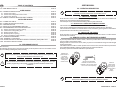
INSTALLATION CERTIFICATE
The undersigned qualified installer attests to have personally fitted the here described system
following the manufacturer instructions.
By :
Sold on :
Type of product :
839
839
................................................
Vehicle :
..........................................................................................................................
INSTALLATION AND
USE MANUAL
UK
GEMINI Technologies S.p.A.
Via Luigi Galvani 12 - 21020 Bodio Lomnago (VA) - Italia
Tel. +39 0332 943211 - Fax +39 0332 948080
Web site: www.gemini-alarm.com
Reg. n.532-A
UNI EN ISO 9001:2008
Made in Italy
AC 2729/UK Rev. 00 - 06/10
UK
USER MANUAL
TABLE OF CONTENTS
2.0 - OPERATING DESCRIPTION
1.0 - PRELIMINARY ADVICE............................................................................................. PAGE 02
USER MANUAL
2.0 - OPERATING DESCRIPTION..................................................................................... PAGE 03
2.1 - Vehicle CDL locking................................................................................................. PAGE 03
2.2 - Vehicle CDL locking and comfort control................................................................. PAGE 03
2.3 - Vehicle CDL unlocking.............................................................................................. PAGE 03
3.0 - REMOTE CONTROL BATTERIES REPLACEMENT.................................................. PAGE 03
INSTALLER MANUAL
4.0 - CONNECTOR TABLE................................................................................................ PAGE 04
5.0 - COMPLETE ELECTRIC DIAGRAM........................................................................... PAGE 05
6.0 - ADD NEW DEVICES.................................................................................................. PAGE 06
7.0 - DELETION OF PROGRAMMED DEVICES............................................................... PAGE 07
8.0 - PROGRAMMABE FUNCTIONS DESCRIPTION....................................................... PAGE 08
8.1 - System self-rearming and door locking.................................................................... PAGE 08
8.2 - Central door locking setting time.............................................................................. PAGE 08
8.3 - Window comfort closure........................................................................................... PAGE 08
8.4 - Double impulse in opening....................................................................................... PAGE 08
8.5 - Doors push-buttons polarity selection...................................................................... PAGE 08
9.0 - SYSTEM PROGRAMMING........................................................................................ PAGE 08
10.0 - WARRANTY CONDITIONS...................................................................................... PAGE 09
11.0 - WASTE ELECTRICAL AND ELECTRONIC EQUIPMENT (WEE) DIRECTIVE........ PAGE 09
12.0 - TECHNICAL SPECIFICATIONS............................................................................... PAGE 09
1.0 - PRELIMINARY ADVICE
Dear Customer,
the following warning signs in the present manual provide important notices to the installer and the
user for installing and using this product correctly:
Indications useful for the user.
This icon provides the user with indications for a diversificated use of the system or it
simply provides indications useful for the use.
!
Indications useful for the installer.
This icon indicates to the installer a diversificated operating, according to the connection
and the programming of the system or it simply provides indications useful for the
installation.
This manual also refers to the LED and to its various optical signals.
The LED is optional and therefore not included in the kit.
2.1 - VEHICLE CDL LOCKING
Press the button on the remote control; the LED will light up steady for 10” and the turn indicators will
blink twice to confirm that the vehicle has been locked .
After this lapse of time, the LED will start blinking until the system is disarmed.
2.2 - VEHICLE CDL LOCKING AND COMFORT CONTROL
If the comfort feature is activated, the vehicle doors will lock and the windows will roll up.
In this case the LED will light up steady during the comfort locking and stay lit for 10” afterwards.
If the remote has two buttons, the comfort feature can be excluded by pressing first the dotted button
(lock) and then the smooth button (comfort exclusion).
2.3 - VEHICLE CDL UNLOCKING
Press the button on the remote control; the turn indicators will blink three times to confirm that the
vehicle has been unlocked..
3.0 - REMOTE CONTROL BATTERIES REPLACEMENT
To prevent problems with the remote control, it has been provided with a device that will signal the
charge condition of the batteries inside.
During normal use of the remote control, when you press a command button the green LED will light
up with a steady light.
If the batteries are too weak for normal operation of the remote control, when the button is pressed the
green LED will start blinking, advising you that it is time to replace the batteries.
For battery replacement follow the indications reported below.
Separate the
plastic shells of
the remote
control, paying
attention to not
damage the
internal circuit.
BATTERIES
Remove the discharged
batteries and insert the new
batteries in their housing, taking
care not to invert the polarity.
Close the
plastic shells
of the remote
and verify the
remote control
works
properly.
Use only batteries of Cr1616 type.
Discard used batteries properly in special dedicated containers.
PAGE 02
USEER MANUAL - PAGE 03
INSTALLER MANUAL
5.0 - COMPLETE ELECTRIC DIAGRAM
4.0 - CONNECTOR TABLE
POSITION
!
WIRE FUNCTION
WIRE COLOUR
-1-
-------
-------
-2-
Doors push-button input
GREEN-BROWN
-3-
Positive under key
YELLOW
-4-
-------
-------
-5-
-------
-------
-6-
Power supply ground
BROWN
-7-
-------
-------
-8-
Positive output with system armed (+A)
PINK
-9-
LED negative output
BLACK
- 10 -
LED positive output
RED
- 11 -
Power suppply positive
RED
- 12 -
Antenna
BLACK
- 13 -
-------
-------
- 14 -
-------
-------
- 15 -
-------
-------
- 16 -
Turn signals positive/negative output
ORANGE
- 17 -
Turn signals positive/negative output
ORANGE
- 18 -
Turn signals positive/negative common
WHITE-RED
- 19 -
CDL
RED-GREY
- 20 -
CDL
RED-BROWN
- 21 -
CDL
RED-BLUE
- 22 -
CDL
YELLOW-BLUE
- 23 -
CDL
YELLOW-BROWN
- 24 -
CDL
YELLOW-GREY
The positive under key (YELLOW wire) and the door signal (GREEN-BROWN wire)
MUST BE CONNECTED for some operating modes and configurations.
Therefore these connections must ALWAYS be done.
!
Before carrying out all
electrical connections,
disconnect the negative
battery terminal and reconnect again after
completion.
KIT2322NF
KIT2323S
BLACK
Antenna, do not tamper
15A
RED
POSITIVE
+
Battery
BROWN
GROUND
Red
Black
RED-GREY
RED-BROWN
RED-BLUE
YELLOW-BLUE
YELLOW-BROWN
YELLOW-GREY
10A
It is reccomended to use a 10A fuse
WHITE-RED
Turn signals relay common
ORANGE
See CDL diagrams
GREEN-BROWN
Doors push-button input
ORANGE
Turn signals output
PINK
Positive output with
system armed (+A)
+30
YELLOW
Positive under key
PAGE 04 - USER MANUAL
INSTALLER MANUAL - PAGE 05
6.0 - ADD NEW DEVICES
!
In order to carry out successfully the operation, it is necessary to make the required
electrical connections (door switch and positive under key).
The system can learn up to 50 remote controls.
For procedure activation follow the indications reported below.
!With the system being disarmed, open and keep opened vehicle driver side door.
!
The following operations must be carried out within four seconds, otherwise the
procedure will be invalidated.
!Turn the vehicle ignition key in “ON”-“OFF”-“ON”-“OFF”-“ON”-“OFF”-“ON” position.
!After the fourth commutation, let the vehicle ignition key to “ON”.
!The system will indicate the remote control learning procedure starting by two flashes of the LED
and the turn indicators.
!
Do not modify the door position otherwise previously saved to memory devices will be
deleted, like described in the next paragraph.
!The system is now waiting to receive the new device code.
!Press the button on th remote control; the system will indicate the new device learning by a flash of
the LED
!Repeat the procedure to save to memory other devices.
!Turn the vehicle ignition key to “OFF” position and close the door.
!The procedure completion will be indicated by one long flash of the LED and one of the turn
indicators.
!
7.0 - DELETION OF PROGRAMMED DEVICES
!
In order to carry out successfully the operation, it is necessary to make the required
electrical connections (door switch and positive under key).
The system includes a devices deletion procedure.
PFor procedure activation follow the indications reported below.
!With the system being disarmed, open and keep opened vehicle driver side door.
!
The following operations must be carried out within four seconds, otherwise the
procedure will be invalidated.
!Turn the vehicle ignition key in “ON”-“OFF”-“ON”-“OFF”-“ON”-“OFF”-“ON” position.
!After the fourth commutation, let the vehicle ignition key to “ON”.
!The system will indicate the devices deletion procedure starting by two flashes of the LED and the
turn indicators.
!Close the door; the LED will be illuminated constantly.
!Keep the door close till the moment, after about eight seconds, the complete deletion of devices
will take place.
!
If the door is opened before 8 seconds, devices will not be deleted.
!The procedure completion will be indicated by LED’s turning off.
!Turn the vehicle ignition key to “OFF” position.
Storing memory is for 50 devices. When an extra one is added, it will automatically
delete the first device registered.
PAGE 06 - INSTALLER MANUAL
INSTALLER MANUAL - PAGE 07
8.0 - PROGRAMMABLE FUNCTIONS DESCRIPTION
10.0 - WARRANTY CONDITIONS
This chapter covers the various features of the system which can be programmed as described in
“SYSTEM PROGRAMMING”.
8.1 - SYSTEM SELF-REARMING AND DOOR LOCKING
This function allows vehicle's protection in case the user disarms accidentally the system.
Thus, the system will be automatically rearmed after 30”, if no intervention on the vehicle is done (i.e.
door opening, engine start).
Together with the system self-rearming, the automatic door locking of the vehicle is done when
running.
Being closed all the doors of the vehicle, turn the ignition key to “ON”; after 20”, all doors will be locked.
By turning the ignition key to “OFF”, all doors of the vehicle will be automatically unlocked.
8.2 - CENTRAL DOOR LOCKING SETTING TIME
Function that allows to select the CDL closure time.
8.3 - COMFORT CLOSURE CONTROL
This function allows activating the comfort control (window closing) when the system is armed.
8.4 - DOUBLE IMPULSE IN OPENING
This function activates twice the opening control and it is used on vehicles with diversified opening.
8.5 - DOORS PUSH-BUTTONS POLARITY SELECTION
This function modifies the alarm input signal (positive or negative) according to the signal deriving
from the door’s button.
This product is guaranteed to be free from manufacturing defects 24 months from the installation date
shown on this warranty coupon, taking into consideration the 1999/44/CE.
Therefore, you are kindly requested to fill entirely the guarantee certificate included in this booklet and
to NOT REMOVE the guarantee label from the device.
The warranty will become void if labels are missing or torn, if the installation certificate is not fully
compiled or if the enclosed sale document is missing.
The guarantee is valid exclusively at authorized Gemini Technologies S.p.A. Service Centers.
The manufacturer declines any responsibility for eventual malfunctions of the device or any damage
to the vehicle electrical system due to improper installation, use or tampering.
11.0 - WASTE ELECTRICAL AND ELECTRONIC EQUIPMENT
(WEEE) DIRECTIVE
In the European Union, this lable indicates that this product must not be disposed of with household
waste. It should be deposited at an appropriate facility to enable recovery and recycling (directive
2002/95/CE, 2002/96/CE and 2003/108/CE).
For information on how to recycle this product responsibly in your Country, please visit the web-site:
Www.eur-lex.europa.eu
!
APPROPRIATE
CONTAINER
ONLY
9.0 - SYSTEM PROGRAMMING
!
Do not modify the functions which have been programmed during the installation.
Entering the programming procedure resets the functions to the default Setting.
12.0 - TECHNICAL SPECIFICATIONS
The system has a “standard configuration” programmed during manufacturing procedure by Gemini.
For programming modification proceed as follows:
!With the system disarmed and doors closed, turn the vehicle ignition key to “ON” position.
!The status LED stay on for one second; during this time, push the button on the remote control.
!Starting of programming procedure is indicated by three flashed of the LED and the turn indicators
and furthermore the LED is permanently illuminated.
!To able and disable the functions, follow the below table, take into consideration that every press
of the push button or rotation of the ignition key will cycle to the next feature. The LED will turn off
briefly after each press of the remote and turn off twice after each key rotation.
FUCTION
STATUS
BUTTON
System self-rearming
Disabled
Enable
Disable
Setting of opening/closing time (1” or 6”)
Selected 1”
Enable 6”
Enable 1”
Disable
Power supply 839
12/24 Vdc
Current absorption @ 12Vdc with system armed and LED flashing
15 mA
Working temperature range
From -30°C to +70°C
Turn signals relay contact capacity
8 A at 20°C
Maximum positive current output when armed (+A)
10 mA
VEHICLE KEY
25” comfort closure
Disabled
Attiva
Doors lock double impulse in opening
Disabled
Attiva
Disable
Selection of doors input polarity
Enabled
negative
Enable positive
polarity
Enable positive
polarity
!Once the last function has been programmed, the system indicates the end of programming
procedure by three flashed of LED and turn indicators.
!Turn the vehicle ignition key to “OFF” position.
PAGE 08 - INSTALLER MANUAL
INSTALLER MANUAL - PAGE 9
Declaration of conformity to type
Dichiarazione di conformità
I hereby declare that the product
Qui di seguito si dichiara che il prodotto
7208E - 7218E
(Name of product, type or model, batch or serial number)
(nome del prodotto o modello, categoria o numero di serie)
Is conform to all relevant essential requirements of the R&TTE-directive 1999/5/EC, issued March
9,1999. According to Annex IV of the R&TTE directive. The following standards and essential radio
test suites published in the “Official Journal” of the European Communities, have been used to
demonstrate the conformity of the product:
Product in class 1 frequency identification - subclass 20
EN 60950-1 (2001) + A11 (2004)
Electrical safety:
Radio and spectrum parameters:
EN 300220-2 V2.1.1 EN 50371 (2002)
Electromagnetic compatibility EMC:
EN 301489-3 V1.4.1 EN 301489-1 V1.6.1
Soddisfa tutti i requisiti applicabili alla tipologia del prodotto e richiesti dalla regolamentazione delle
telecomunicazioni secondo direttiva R&TTE 1999/5/CE allegato IV tramite l’utilizzo delle norme
pubblicate nella gazzetta ufficiale della Comunità Europea:
Prodotto in frequenza identificata come classe 1 - sottoclasse 20
Sicurezza elettrica:
EN 60950-1 (2001) + A11 (2004)
Radio e parametri di trasmissione:
EN 300220-2 V2.1.1 EN 50371 (2002)
Compatibilità elettromagnetica EMC:
EN 301489-3 V1.4.1 EN 301489-1 V1.6.1
The product can be used in the following European Countries:
Il prodotto può essere immesso nei seguenti Stati Europei:
Company responsible for placing on the market:
Società responsabile per l’immissione nel mercato:
Address:
Indirizzo:
Point of contact:
Persona di contatto:
A, B, D, DK, F, FR, GR, IR, I, L, NL, P,
SP, S, UK
GEMINI TECHNOLOGIES S.p.A.
Via Luigi Galvani 12 - 21020 BODIO LOMNAGO (VA) ITALY
Andrea Rossi
Bodio Lomnago - 19/09/2003
(Signature) - (Firma)