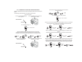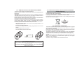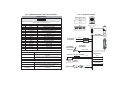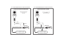
1
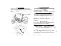
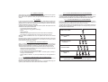
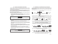
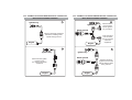
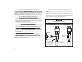
System type:
...........................................................................
Sold on:
...........................................................................
By:
Installed on bike
model, number
plate/frame:
954
INSTALLATION AND
USE MANUAL
UK
GEMINI Technologies S.p.A.
Via Luigi Galvani 12 - 21020 Bodio Lomnago (VA) - Italia
Tel. +39 0332 943211 - Fax +39 0332 948080
Web site: www.gemini-alarm.com
NOTE: please send a copy to the insurance company if secessay.
For all EU Countries
AC 2737UK-REV.00- 10/03/09
UK
CONTENTS
1.0 - PRELIMINARY ADVICE
USER MANUAL
2.0 - ALARM SYSTEM CONTROL DEVICES DESCRIPTION
2.1 - Remote control
2.2 - Electronic key
3.0 - SYSTEM OPERATION WITH BASIC CONFIGURATION
3.1 - Arming
3.2 - Trunk open or seat lifted-up signalling
3.3 - Neutral time
3.4 - Siren exclusion
3.5 - Built-in sensors exclusion
3.6 - Armed condition
3.7 - Alarm
3.8 - Limiting the alarm acoustic signal
3.9 - Neutral time between two alarm signals
3.10 - System disarming without alarm memory
3.11 - System disarming with alarm memory
4.0 - EXTRA FUNCTIONS DESCRIPTION
4.1 - Acoustic and optic signalling
4.2 - Remote controlled panic alarm
4.3 - Shock sensor
4.4 - Shock sensor adjustment
4.5 - Passive arming
4.6 - Anti-hijacking function
4.7 - Pre-alarm
4.8 - System self-rearming
5.0 - SLEEP MODE ACTIVATION/DEACTIVATION
6.0 - HAZARD SIGNALLING
7.0 - USE AND MAINTENANCE
8.0 - SYSTEM UNLOCK PROCEDURE BY PIN-CODE
9.0 - EXAMPLE OF SYSTEM UNLOCK BY PIN-CODE
10.0 - EXAMPLE OF PIN-CODE PERSONALIZATION
11.0 - REMOTE CONTROL BATTERIES REPLACEMENT
12.0 - WASTE ELECTRICAL AND ELECTRONIC EQUIPMENT (WEEE)
DIRECTIVE
13.0 - WARRANTY CONDITIONS
CONTENTS
INSTALLER MANUAL
14.0 - INSTRUCTIONS FOR ALARM SYSTEM INSTALLATION
15.0 - TECHNICAL DATA
16.0 - CONTROL UNIT POSITIONING
17.0 - CONTROL UNIT POSITIONING FOR CORRECT OPERATION OF
THE DISPLACEMENT SENSOR
18.0 - ACCESSORIES POSITIONING
18.1 - Receptacle for electronic key
18.2 - Perimetral push-button (optional)
19.0 - CONTROL UNIT SEALING
20.0 - SUMMARY REPORT FOR THE ELECTRICAL CONNECTIONS
21.0 - ELECTRIC DIAGRAM
22.0 - ENGINE IMMOBILISATION CONNECTING DIAGRAM (ground wire)
23.0 - ENGINE IMMOBILISATION CONNECTING DIAGRAM (cut wire)
24.0 - EXAMPLE OF ENGINE IMMOBILISATION CONNECTION WITH
SPECIFIC WIRING HARNESS
25.0 - ELECTRICAL CONNECTIONS WITH SPECIFIC WIRING
HARNESS
25.1 - Engine immobilisation connection
25.2 - Turn signals connections
25.3 - Ground connection
25.4 - Receptacle for electronic key with built-in LED
26.0 - INSTRUCTION FOR DIODE APPLICATION
27.0 - LEARNING OF NEW DEVICES (with ground wire)
28.0 - LEARNING OF NEW DEVICES (without ground wire)
29.0 - EXTRA FUNCTIONS PROGRAMMING
30.0 - EXAMPLE OF PROGRAMMING
1.0 - PRELIMINARY ADVICE
Dear Customer,
Thank you for having chosen a Gemini alarm system.
This manual has been written for you so that you can acquaint yourself with
and get the best operation results with your motorbike alarm system.
We recommend you to read this manual both carefully and entirely here you
will find some important information, advices and warnings that will assist you
in operating and making the most of your device.
Gemini’s alarm systems, model 954, are specifically designed for two-wheel
vehicle protection.
We kindly ask you to check the model you own, verifying the function and the
accessories available with your installer.
Thanks to a safety and comfort functionality, you can program the device
according to your actual needs.
Indeed, although equipped with a number of available functions, the device is
programmed and delivered to the final customer in the so-called “basic”
configuration.
Your alarm is also provided with a PIN-CODE.
In case of emergency, the alarm may be switched off by using the vehicle
ignition key, without the need of control modules such as remote controls and
electronic keys.
In order to prevent unauthorized alarm deactivation, we strongly recommend
to change the initial code, which is the same in all systems by factory settings.
For this reason too, we also suggest to keep this manual safely for future use.
The following signs, intended for the installer or the user, indicate particular
functions or connections as follows:
! WARNING
It shows a real risk of severe damages to the vehicle and to its alarm
system in case these instructions are not complied with.
CAUTION
It shows a risk of damages to the system or of any operative malfunctions
of the system in case these instructions are not complied with.
We also recommend you to always wear your crash helmet, keep lights on and
observe the speed limit, when riding your motorbike.
Enjoy your reading… and have a nice trip!
USER MANUAL
2.0 - DESCRIPTION OF ALARM SYSTEM
CONTROL DEVICES
In order to use the alarm system, it needs to receive commands by the user;
this can be done by means of remote controls and electronic keys.
A further possibility to deactivate the system, when needed, is given by the
PIN-CODE.
Such procedure can be activated by means of the ignition key of the vehicle
itself and is detailed in the relevant chapter.
2.1 - REMOTE CONTROL
The remote control is the main user “interface”; therefore, we recommend you
to acquaint yourself with it.
The remote control buttons activate several functions that differ according to
the operational condition and the system programming.
Please also note that buttons have been made different in form, in order to be
better recognized and identified.
The alarm activation/deactivation button is dotted, while the siren button is
smooth.
To prevent problems with the remote control, it has been provided with a device
that will signal the charge condition of the batteries inside.
During normal use of the remote control, when you press a command button
the green transmission LED will light up with a steady light.
If the battery charge drops below the level needed to assure correct operation
of the remote control, when you press a command button the green
transmission LED will blink, advising you that it is time to replace the batteries.
Button Nr.1: !Alarm system
arming/disarming.
!Anti hijacking function
activation.
Button Nr.2: !Hazard function activation.
!Anti hijacking function
activation.
!Panic alarm
activation/deactivation.
!Siren control during alarm
conditions.
!Siren control during system
activation.
Signalling
LED
Button Nr.1
Button Nr.2
2.2 - ELECTRONIC KEY
The electronic key can be considered a kind of “simplified remote control”.
As a matter of fact, in emergency situations (e.g. a failure in the remote
control), it can activate and deactivate the alarm, or activate and deactivate the
anti-hijacking function (if previously programmed).
To use the electronic key, simply put it on the receptacle, and join the metallic
contacts.
The receptacle also incorporates the alarm system status LED.
Electronic key
Example of receptacle
positioning on the vehicle
plastic side cover.
3.0 - SYSTEM OPERATION WITH
BASIC CONFIGURATION
3.1 - ARMING
Pressing the (dotted) button N.1 on the remote control or inserting the
electronic key into the receptacle will activate the system.
This action is indicated by one long flashing of the turn signals, two short
acoustic signals and the permanent turning on of the LED.
3.2 - TRUNK OPENED OR LIFTED-UP SEAT SIGNALLING
During alarm system activation, should the seat or the trunk be opened, the
system will signal the failure by means of a low-tone signal after the alarm
arming signalling.
In any case the system will be activated and, at the end of the “neutral time”, an
alarm condition will be generated.
3.3 - NEUTRAL TIME
When the activation signals are finished, the system goes in standby or
neutral-time condition, which is signalled with a steady-light LED.
This time duration is about 20 seconds.
The engine immobilization function and the connectors for optional modules
are already active.
3.4 - SIREN EXCLUSION
During the first 4 seconds of neutral time, the alarm siren can be deactivated,
by simply pressing (smooth) button N. 2 on the remote control (obviously after
N. 1 remote control push-button pressure, system arming).
Siren exclusion will be signalled by a short flashing of the turn signals.
CAUTION
When the siren is excluded, the alarm signals will be changed; indeed
only visual signals will be active, i.e. with flashing of the turn signals, but
the engine immobilization function will still work.
The siren sound exclusion is bound to the single arming cycle.
Electronic key
Example of receptacle positioning on the vehicle dashboard.
3.5 - BUILT-IN SENSORS EXCLUSION
During the first 4 seconds of neutral time, it is possible to exclude the alarm
system internal sensors (shock and lifting); to do this, you must just put the
electronic key into the specific receptacle, after the alarm system has been
activated.
The exclusion is bound to a single arming cycle and will be indicated by a short
flashing of the status LED.
3.6 - ARMED CONDITION
At the end of the neutral time, after about 20 seconds, the alarm system goes in
the armed condition and signals this with a blinking LED.
From now on, the system is ready to signal possible attempts to force the
vehicle.
3.10 - SYSTEM DISARMING WITHOUT ALARM MEMORY
Pressing the button N.1 (dotted) on the remote control or inserting the
electronic key in the receptacle will deactivate the system.
The alarm system will signal this change of status with the LED switched off,
three beeps and three flashes of the direction indicators at the same time.
3.7 - ALARM
If, during the armed condition, should occur any theft attempt against the
vehicle, the alarm system will signal this by activating the high-volume siren,
lighting up the red LED with a steady light and causing the direction indicators
to flash repeatedly for about 30 seconds.
The alarm may be activated by different causes (which also depend on the
activated functions) described below:
!Cut-off of the power supply cables.
!Turn on the ignition key (positive under key).
!Shock.
!Shifting attempt.
!Seat/trunk opening (if the protection push-button has been installed).
!Panic alarm, by pushing button N. 2 (smooth) on the remote control.
When the alarm conditions are over, the system will revert to the armed
condition.
During the alarm condition it is still possible to deactivate the siren sound and
the turn signals flashes by pushing button N. 2 (smooth) on the remote control
(without disarming the alarm system).
3.11 - SYSTEM DISARMING WITH ALARM MEMORY
If during the armed period attempts have been made to force the vehicle,
during the deactivation stage the alarm will signal the event with two flashes of
the turn signals and, simultaneously, with two low-tone beeps.
The last cause of alarm will be signalled with one or more flashes of the turn
signals and a corresponding number of beeps, according to the type of event,
like indicated in the table below.
3.8 - LIMITING THE ACOUSTIC SIGNALS
Alarm conditions caused by shock, displacement, seat/trunk opening or
ignition key will be signalled by the activation of the siren for 7 times for each
cause. From the eighth alarm condition on, the siren will cease to be active.
This deactivation of the siren is performed because of these simple reasons:
!Observance of the regulations in force in the subject of acoustic emissions
caused by vehicle alarm systems.
!Power saving to maximize the vehicle battery.
!It is no use keeping the alarm on if, after 7 acoustic signals, nobody is
coming to check the vehicle.
!Noise pollution reduction, to prevent penalties as per the regulations in
force.
3.9 - NEUTRAL TIME BETWEEN TWO ALARM SIGNALS
Once the alarm cycle is over, the device will ignore any other alarm cause for 5
seconds, while keeping the LED steadily on
During the neutral time between alarm signals, it is possible disarming the
system by PIN CODE, like as described in the relative chapter.
Shock sensor alarm:
Starting attempt
alarm:
Trunk open or lift-up
seat alarm:
Cut wires alarm:
Shifting-hitting
alarm:
CAUTION
If regulated with “reduced” sensibility the shock alarm has thee pre-alarm
optical signals, which are indicated by the LED’s flashing.
4.0 - DESCRIPTION OF THE EXTRA FUNCTIONS
The table below shows the programmable functions.
The manufacturer supplies the system with some of these functions disabled
(in order to achieve a good trade-off between ease and completeness of use),
being the shock sensor regulated with standard sensibility.
Factory setting
Function
Acoustic signals
Panic alarm
Shock sensor
Shock sensor sensibility
Passive arming
Anti-hijacking procedure
Pre-alarm
Anti-distraction
Stato
Enabled
Enabled
Enabled
Standard
Disabled
Disabled
Disabled
Disabled
4.1 - ACOUSTIC AND OPTIC SIGNALLING
In the different using conditions, the alarm system signals the current
operation or the alarm memory.
This is done using the turn signals an the LED for the optical signals and using
the siren for the acoustic signals (the last one can be disabled).
FUNCTIONNING
During the stages of activation, deactivation, alarm memory, function
programming and learning of new devices, the system will produce specific
acoustic and optic signals in order to show which function is being run.
Optic signallings concern either LED or turn signals.
The acoustic signals can be high-tone or low-tone.
4.2 - REMOTE CONTROLLED PANIC ALARM
It allows to generate an alarm condition by pressing button N. 2 (smooth) on
the remote control.
The panic signals can be as many as desired, but a minimum 5-seconds
interval must occur between two consecutive signals.
FUNCTIONNING
Pressing button N. 2 on the remote control will activate the siren and the
direction indicators for about 30 seconds.
To deactivate the panic alarm, just press again button N. 2 on the remote
control.
This alarm signalling can be activated indifferently of the system status
(activated/deactivated).
4.3 - SHOCK SENSOR
The system may generate an alarm condition caused by a shock or a shifting of
the vehicle.
The shock sensor is buil in the alarm system and is adjustable.
FUNCTIONNING
In armed condition, if the vehicle is hit or shifted, the sensor included in the
alarm system will detect this anomaly and generate an alarm.
If regulated with “reduced” sensibility the shock alarm has thee pre-alarm
optical signals, which are indicated by the LED’s flashing.
4.4 - SHOCK SENSOR REGULATION
This function aims to modify the shock sensor sensibility, which is regulated by
Gemini on “standard”.
FUNCTIONNING
If it is necessary to regulate the shock sensor, by increasing or decreasing its
sensibility, push the button Nr.1 or Nr.2 of the remote control, during the
programming phases.
4.5 - PASSIVE ARMING
This function allows the user to leave the vehicle sure that the alarm system
protection arms itself automatically.
FUNCTIONNING
Once the engine is switched off, the system automatically activates the
passive arming.
This will be signalled by one turn signals flash, two LED flashes and two siren
high-tone beeps
After 35 seconds the system will activate steadly, signalling the operation with
a single flash of the turn signals, two acoustic signal and the lighting up of the
LED (blinking).
The procedure can be interrupted, by turning on the ignition switch within 35”.
If the trunk or the seat are open, the passive arming time will be interrupted,
until the trunk or the seat closing.
4.6 - ANTI-HIJACKING FUNCTION
This function ensures a sort of protection against criminals when a theft
attempt happens while the vehicle is in use.
The function indeed allows to activate the system while stopping the vehicle
with the ignition key switch on and the engine running.
FUNCTIONNING
With the ignition key switch on, it is possible to activate the anti-hijacking
function in the ways reported in the next page.
!By pressing button N. 1 on the remote control.
!By pressing button N. 2 on the remote control.
!By inserting the electronic key in the receptacle.
CAUTION
The activation of the anti-hijacking function will be signalled by the system
with two rapid flashes of the turn signals and a steady LED.
Once enabled the anti-hijacking function, the remote controls won’t work
anymore.
20 seconds after the activation, the system will immobilize the vehicle’s
engine; two seconds later the siren will be activated at high volume and the
direction indicators will start blinking repeatedly.
This signalling will continue for a minute and, after this time, the siren will be
deactivated; the turn signals will continue blinking until the anti-hijacking
function is disabled.
To deativate the function insert the electronic key in the receptacle.
4.7 - PRE-ALARM
In alarm condition, this implies the activation of the siren for just 2,5 seconds
(first 3 alarm cause only) rather than the standard 30 seconds.
This considerably reduces power consumption while preserving the vehicle’s
battery, and it reduces the environmental acoustic pollution.
FUNCTIONNING
When the system is activated, providing an alarm condition is generated (i.e.
the vehicle is accidentally hit), the siren will be activated for about 2,5 seconds.
This condition of pre-alarm will be activated for the first 3 alarm causes.
Indeed, from the fourth cause on, the siren will be activated for about 30
seconds.
The alarm cycles will be reset every time the alarm is deactivated or when the
panic alarm is activated.
4.8 - SYSTEM SELF-REARMING
This function protects the vehicle in case the system would be unintentionally
deactivated.
FUNCTIONNING
The system is activated by the user, then unintentionally deactivated (e.g. the
relevant button on the remote control is pressed).
The user, unconscious about this, will leave the vehicle unprotected, although
being sure of the contrary.
35 seconds after this unintentional deactivation, the alarm will automatically
reactivate, signalling this with the standard acoustic and optical signals.
5.0 - SLEEP MODE ACTIVATION/DEACTIVATION
When the vehicle is not used, it is possible to switch completely off the alarm
system (sleep mode) in order to reduce the battery charge consumption.
To activate this function, proceed as follows:
!Turn the ignition key to “ON” position; the LED will light for about one
second.
!After the LED flash put the electronic key into the receptable, within 4
seconds; an acoustic signal will indicate that the system is turned off.
!Turn the ignition key of the vehicle to “OFF” position.
!To re-activate the alarm system, turn the ignition key of the vehicle to “ON”
and “OFF”.
6.0 - HAZARD SIGNALLING
The hazard signalling is useful when you want to park the vehicle, being the
vehicle engine off and the turn signals on.
To activate/deactivate this function, proceed as follows:
!With system disarmed, turn the ignition key to “ON”; the LED will be
illuminated for about 1”.
!During this period, push the button N.1 of the remote control.
!Turn the ignition key to “OFF”; the turn signals will start flashing.
!To deactivate the function, you must just turn again the ignition key to “ON”
(and eventually to “OFF”), or arm and disarm the system.
7.0 - USE AND MAINTENANCE
Please note that the alarm system is still an electronic device, so must be
handled carefully.
The following are simple hints which are useful if you want to prevent device
damage because of an improper use.
!Do not clean the control unit with water but only use a damp cloth.
!Do not use power supply voltages which are different than those specified
by the factory.
!If the motorbike is cleaned with a washing machine, be careful not to
directly expose the alarm system to the water jet.
! WARNING
Gemini Technologies S.p.A. is not responsible for damages to the system
in case of an improper use of it.
8.0 - UNLOCK PROCEDURE BY PIN-CODE
9.0 - EXAMPLE OF SYSTEM UNLOCK BY PIN-CODE
The PIN-CODE procedure allows deactivating the alarm system in case of
emergency, that is to say when, for any reason whatsoever, the remote control
or the electronic key cannot be used.
To have the system deactivated, the final user shall “communicate” a four-digit
numeric code to the system, originally set up by the manufacturer as 1-1-1-1.
Due to obvious safety reasons, we recommend to replace this original code
with another user’s customized code.
Please see next pages to carry out this operation, than read the instructions
below to unlock the alarm with the PIN-CODE:
!Cause an alarm situation; as soon as the alarm condition is finished, the
installed LED will turn on and stay fixed for about 5”.
!While the LED is on with a fixed light, connect and disconnect the ignition
key switch.
To better understand the alarm system unlock by means of PIN-CODE, please
refer to the following example considering the case of a PIN-CODE formed by
these digits: 2-3-4-1.
CAUTION
If, during this phase, the ignition key switch is kept connected for more
than 5”, the system will read this as a theft attempt, so causing another
alarm condition.
!The installed LED will turn off so showing the beginning of the unlock
procedure.
!After 4” from the LED turning off, it will start flashing for 9 blinks.
!As soon as the number of blinks is equal to the first digit of the PIN-CODE,
connect and disconnect the ignition key switch, so confirming the first digit
of the code.
!After others 4”, this LED will start flashing for 9 blinks again.
!As soon as the number of blinks is equal to the second digit of the PINCODE, connect and disconnect the ignition key switch, so confirming the
second digit of the code.
!Repeat the same as above for the remaining two digits to be entered.
!As soon as the last digit is stored, the system will be deactivated by
signalling this operation as shown in the paragraph 3.11, “system disarming
with alarm memory”.
CAUTION
In case the LED blinks exceeds the number of 9, this procedure will fail
and this will be read as a theft attempt.
After the system is armed, wait for the end of “neutral time” and then cause
an alarm condition.
Key in
“ON” position.
An alarm condition
will occur.
Key in “OFF”
position.
As soon as the alarm condition is finished, the installed led will turn on and
stay fixed for about 5”.
While the LED is on, connect and disconnect the ignition key, the LED will turn
off showing the beginning of the unlock procedure by means of PIN-CODE.
LED fixed
on for
about 5”.
Key in
“OFF”
position.
Key in “ON”
position.
LED turned off.
Unlock
procedure starts
After 4” from the led turning off, it will start blinking.
As soon as the number of blinks is equal to the first digit of the PIN-CODE
(which is 2 in this case), connect and disconnect the ignition key switch.
After another 4”, this LED will start blinking again.
As soon as the number of blinks is equal to the second digit of the PINCODE (which is 3, in this case), connect and disconnect the gnition key
switch.
4 Sec.
4 Sec.
1st. number: “2” “ON” “OFF”
2nd. number: “3”
“ON” “OFF”
After 4 seconds, the system restarts counting to set up the other following
two digits (which are 4 and 1 in this case).
4 Sec.
4 Sec.
3rd. number: “4”
“ON” “OFF” 4th. number: “1” “ON” “OFF”
As soon as the fourth digit of the PIN-CODE is entered, the alarm system
will be deactivated by showing the last alarm cause.
PAG.13
10.0 - EXAMPLE OF PIN-CODE PERSONALIZATION
To better understand how to set up the PIN-CODE, please refer to the example
below.
The following customized PIN-Code 2-3-4-1 will be entered.
Push both remote control buttons at the same time.
The LED will go off.
LED
off
Turn off the system.
Connect the BROWN-GREEN
wire to ground.
Turn the ignition key in “OFF” position.
Open the saddle of the vehicle if the
safety button is fitted.
Key in “OFF” position.
BROWN-GREEN
NEGATIVE
After four seconds have passed, the LED will begin a series of nine flashes.
Turn the ignition key in “ON” when we intends to memorize the first
figure of the new PIN-CODE.
Turn the ignition key in “ON” position.
Key in “ON”
position.
Key in “ON” position.
The LED installed on the vehicle will light up for 0.5 seconds.
During this time period, press both buttons on the remote control.
The alarm will emit two acoustic signals and then it will light the LED.
Boop
Boop
0.5
Sec.
Remove from negative the
BROWN-GREEN wire.
Afte four seconds have passed, the LED will begin a new series of nine
flashes.
Repeat the operations described above to insert the second number.
Fixed
light
Close the saddle of the vehicle if the
safety button is fitted.
Key in “ON”
position.
LED
off
Key in “OFF”
position.
Repeat the same operations described above to insert the other two numbers.
When you have finished inserting the fourth number of the pin-code, the
system will automatically exit the procedure. It will confirm the successful
termination with two low tone acoustic signals and one high tone signal.
BROWN-GREEN
Last
number.
NEGATIVE
LED
off
Key in “OFF”
position.
Key in
“ON”
position.
Key in
“OFF”
position.
Boop
Boop
11.0 - REMOTE CONTROL BATTERIES REPLACEMENT
The remote control operates using alkaline batteries.
Under normal use conditions of the remote control these will gradually lose
their charge.
The more you use the remote control, the sooner the batteries will become
discharged.
To prevent problems with the remote control, it has been provided with a device
that will signal the charge condition of the batteries inside.
During normal use of the remote control, when you press a command button
the green transmission LED will light up with a steady light.
If the battery charge drops below the level needed to assure correct operation
of the remote control, when you press a command button the green
transmission LED will blink, advising you that it is time to replace the batteries.
For battery replacement follow the indications reported below:
!Separate the plastic shells of the remote control, paying attention to not
damage the internal circuit.
!Remove the discharged batteries.
!Insert the new batteries in their housing, being careful to not invert the
polarity.
!Close the plastic shells of the remote.
!Verify the efficiency of the remote control.
BATTERIES
! WARNING
Use only batteries CR1616 type.
Using batteries different from those advised can seriously damage the
remote control unit.
Do not discard used batteries in the environment; they should be disposed
in appropriate containers.
12.0 - WASTE ELECTRICAL AND ELECTRONIC EQUIPMENT
(WEEE) DIRECTIVE
In the European Community, the present label indicates that this product must
not be disposed of with household waste.
It should be deposited at an appropriate facility to enable recovery and
recycling (directive 2002/95/CE, 2002/96/CE and 2003/108/CE).
For information on how to recycle this product in your Country, please visit the
web-site: www.eur-lex.europa.eu
!
APPROPRIATE
CONTAINER
ONLY
13.0 - WARRANTY CONDITIONS
This product is guaranteed to be free from manufacturing defects for a period
of 24 month from the installation date shown on this warranty, in compliance
with the directive 1999/44/CE.
Please fill-in entirely the guarantee certificate included in this booklet and do
NOT REMOVE the guarantee label from the device.
The warranty will become void if labels are missing or torn, if the installation
certificate is not fully compiled or if the enclosed sale document is missing.
The guarantee is valid exclusively at Authorized Gemini Technologies S.p.A.
Centers.
The manufacturer declines any responsibility for eventual malfunctions of the
device or any damage to the vehicle electrical system due to improper
installation, use or tampering.
This alarm is solely intended to be a theft-deterrent device.
INSTALLER MANUAL
16.0 - CONTROL UNIT POSITIONING
14.0 - INSTRUCTIONS FOR ALARM
SYSTEM INSTALLATION
Before starting the installation procedures, please pay a special
attention to what follows:
!Read this manual thoroughly: it includes important information so that a job
can be carried out workmanlike; moreover, the manual is also an integral
part of the alarm system.
!All information included in this publication are based on technical
characteristics of GEMINI TECHNOLOGIES S.p.A. alarm systems.
!GEMINI TECHNOLOGIES S.p.A. reserves its right to make any changes
to these characteristics without giving prior notice to its potential buyers.
!No part of this document can be reproduced without GEMIN’s prior written
authorization.
!GEMINI original accessories have been designed for this alarm system
and they have been tested on it.
As the manufacturer cannot check their market availability, the installer or
the final user of the vehicle shall bear the risk of selecting the part.
15.0 - TECHNICAL DATA
Power supply
Power supply range
Load @ 12-Vdc
Currente absorption in sleep-mode
Sound power radiated
Relay capacity
12 Vdc
9Vdc-15Vdc
<0,7mA (system armed and
flashing LED)
< 1µA
118 dBA @ 1 meter
8A
! WARNING
Installing the alarm system in this
position, will promote water infiltration
trought the rubber cap.
Note that the water entering the unit
can damage the electronic circuity,
making both system and vehicle
unreliable.
!Installing tha control unit in this position, will
prevent water entering the unit through the
rubber cap.
!It is important to position the wiring shealt so
that it forms a kind of siphon.
!The gearcase must be placed in such a way so
that the siren may play its sound without
restraints and can be shielded against the
weather agents at the same time.
!The control unit positioning must not be
performed near moving mechanical parts and
electric or electronics parts (which could
generate high intensity electromagnetic
disturbances) as well as near such devices,
which during the vehicle operation could reach
high temperatures.
!The alarm gearcase must not be directly
assembled on the vehicle metallic frame.
17.0 - CONTROL UNIT POSITIONING FOR CORRECT
OPERATION OF THE DISPLACEMENT SENSOR
4
In order to guarantee the correct operation of the displacement sensor, which
is incorporated in the alarm, install the alarm following the instructions below.
1
OK
OK
OK
OK
Figure “4” shows the displacement sensor operation, being the alarm fixed
in lateral position.
This positioning is suitable only for vehicles equipped with lateral kickstand.
It is possible to install the alarm either to the right or the left side of the
vehicle, on condition that the siren grid is turned toward the right side of the
vehicle (opposite to the kickstand).
5
2
OK
Figures “1” show the
horizontal positioning of the
alarm, while figures “2”, show
the maximum applicable
inclination.
3
45°
MAX
45°
MAX
Figure “3” shows the
displacement sensor
operation, being the alarm
fixed in horizontal position.
By fixing the control unit with
the siren grid turned upwards
or downwards, but anyway in
horizontal position, the
sensor will intervene when
the vehicle is moved in any
direction.
Figure “5” shows the displacement
sensor operation, being the alarm
fixed in vertical position.
This positioning is suitable only for
vehicles equipped with central
kickstand.
To avoid eventual water infiltration, it
is suggested to fit the wire boot
turned downwards.
! WARNING
Operation test is suggested in all types of alarm positioning, when
installation has been completed.
18.0 - ACCESSORIES POSITIONING
19.0 - CONTROL UNIT SEALING
18.1 - RECEPTACLE FOR ELECTRONIC KEY
The receptacle with buil-in LED must be set up where the user can easily see
and access to it.
Please remember that the LED represents the first deterrent against an illintentioned person.
Before drilling the plastic parts of the vehicle, please check the handlebar with
respect to the steering lock on ON.
You will thus avoid putting the receptacle in such a way as to be covered by the
handlebar when the vehicle is parked.
Should you put them otherwise, we always recommend paying a particular
attention during the drilling phase, not to damage the vehicle.
The fastening drilling diameter for the electronic key slot is equal to 13mm.
Sealing the control unit
Put the electronic
key receptacle with
built-in LED in such
a way so that they
can be easily seen
and found.
Electronic key
Control unit sealed
18.2 - PERIMETRAL PUSH-BUTTON (OPTIONAL)
This push-button, if fitted, must be placed in such a way as to detect any saddle
or trunk opening but it must not be found from their outer part.
The alarm threshold adjustment shall be carried out very carefully, to prevent
from any false alarm.
The push-button terminal to be earthed must not be connected to the frame as
it is not connected to the battery negative pole.
This connection can be made to a cable, which constantly provides for a
negative pole (ex.: turn signal lamp earth).
If the under-seat push-button is not installed, the GREEN/BROWN wire is free.
We suggest you to keep this wire available for other possible uses.
20.0 - SUMMARY REPORT FOR THE ELECTRICAL
CONNECTIONS
21.0 - ELECTRIC DIAGRAM
CAUTION
The tables below refer to the generic wiring harness (KITCA 417).
Refere to installation sheets for available specific wiring harness (wwwgemini-alarm.com private area).
Pos.
Wire colour
Wire function
-1-2-3-4-5-6-7-8-9- 10 - 11 - 12 - 13 - 14 - 15 - 16 -
Brown
Brown
White-Violet
Green-Brown
----Yellow
Black
Green
Grey
White
White-Grey
Orange
Red
Orange
Black
Electronic key ground
Ground
Self learning push-button input
Perimetral push-button input
Not used
Not used
Positive under key
LED negative output
Electronic key input
Engine block (N.C.)
Engine block (Com.)
Engine block (N.O.)
Turn signals
Positive
Turn signals
Antenna
16 15 14 13 12 11 10 9
8 7 6 5 4 3 2 1
Receptacle
with built-in LED
Orange
Turn signals
connections
White
Grey
ELECTRICAL CONNECTIONS FOR EARTHED ENGINE BLOCK
WIRE COLOUR
White
White/Grey
CONNECTION TO BE PERFORMED
Connect to a vehicle permanent negative pole
(do not connect to the frame)
Connect to the cable end which, if earthed, will lock
the engine
15A
Seat-trunk
push-button
Installation
reccomanded
in all cases
Green/Brown
Ground
CONNECTION TO BE PERFORMED
Connect to the cut crop end coming from the ignition
key switch
Connect to the cut cable end coming from the
vehicle electric system
15A
Orange
ELECTRICAL CONNECTIONS FOR DISCONNECTED ENGINE BLOCK
WIRE COLOUR
Electronic key
Engine block
Optional fuse (reccomended)
10A
Red
Brown
Battery
12 Volt
Grey
White/Grey
White
Vehicle
battery
Green/Black
Brown
Yellow
Ignition key
22.0 - ENGINE IMMOBILISATION CONNECTING DIAGRAM
ENGINE BLOCK WITH GROUNDED WIRE
23.0 - ENGINE IMMOBILISATION CONNECTING DIAGRAM
ENGINE BLOCK WITH CUT WIRE
Most small motorbikes with
two-stroke engines use
this system.
Most large motorcycles with
four-stroke
engines use this system.
White
White
White/Grey
Ground
Grey
Ignition key
Engine immobilisation wire
Ignition key
Engine immobilisation wire
Cut
To vehicle’s engine
To vehicle’s engine
24.0 - EXAMPLE OF ENGINE IMMOBILISATION CONNECTION
WITH SPECIFIC WIRING HARNESS
24.0 - EXAMPLE OF ENGINE IMMOBILISATION CONNECTION
WITH SPECIFIC WIRING HARNESS
3
1
Ignition key
Ignition key
Alarm system
Vehicle’s electrical equipment
before the installing of the
specific wiring harness
Engine
Engine
2
Ignition key
Disconnect the ignition
connector from
the vehicle’s electrical
equipment
Engine
Insert the alarm
unit connector
into the ignition
key connector
Insert the alarm
unit connector
into the vehicle’s
electrical
equipment
4
Ignition key
Alarm system
Vehicle’s electrical
equipment connected
with the alarm system
wiring harness
Engine
25.0 - ELECTRICAL CONNECTIONS WITH SPECIFIC
WIRING HARNESS
Once the secure position of the system and its peripherals (receptacle for
electronic key, under-saddle or trunk push-button) has been found, the
electrical connections can be carried out.
Please pay a special attention to the following instructions in order to correctly
perform this phase and refer to the drawing shown into the specific paragraph.
25.1 - ENGINE IMMOBILISATION CONNECTION
!Disconnect the ignition key switch block connector (or the equipped device
for engine immobilisation) from the vehicle electric equipment connector.
!Insert the alarm system wiring connectors as follows: one into the ignition
key switch connector and another into the vehicle electric equipment (or the
equipped device for engine immobilisation).
!Connectors can not be inverted because they are polarized.
25.2 - TURN SIGNALS CONNECTION
!Connect the alarm system wiring harness to the vehicle cables having the
same colour and providing for a positive pole to the direction indicator light.
25.3 - GROUND CONNECTION (WHEN NOT AVAILABLE ON THE
IGNITION KEY SWITCH BLOCK)
!In case the vehicle has no earthed cable on the switch key block (it usually
happens with four-stroke engine vehicles) the alarm system earth cable
needs to be connected to a vehicle conductive part (ex.: earth cable of the
turn signal lamps).
!Do not connect the earth cable to the vehicle frame.
25.4 - RECEPTACLE FOR ELECTRONIC KEY WITH BUILT-IN LED
Connect the slot BLACK 2-way connectors to the correspondent alarm system
2-way BLACK connectors.
Cables inside the two connectors are RED and BLACK as for the first and
BROWN and GREEN as for the second.
26.0 - INSTRUCTIONS FOR DIODE APPLICATION
In order to verify if it must be installed on the vehicle, please follow the
procedure below:
!Switch on the turn signal switch of the direction indicator lights and arm the
system.
!Verify that the instrument panel lights together with the direction indicator
lights.
!If so, install a diode as specified in the diagram below.
!If the instrument panel does not light, do not connect the diode.
CAUTION
Diode installation is not necessary, if in phase of alarm system arming the
instrument board is activated too.
Actually, the absence of a diode does not imply any damage for the vehicle.
Vehicle electrial
equipment before
Turn signal relay
Vehicle electrial
equipment after
Turn signal relay
WHITE wire
Cut
Diode into
the electrical
equipment
BLACK wire
Cable providing for
the positive pole to
the turn signals lamp
flasher by means of
the switch key
PAG.14
Vehicle original
equipment
Vehicle original
equipment
27.0 - LEARNING OF NEW DEVICES
28.0 - LEARNING OF NEW DEVICES
(BY BROWN/GREEN WIRE GROUND CONNECTION)
(WITHOUT BROWN/GREEN WIRE GROUND CONNECTION)
The system is supplied with two remote controls and an electronic key, but
saving to memory or replacement of electronic keys or radio controls could be
necessary.
To perform these steps, follow the procedure below, keeping in mind that the
passive arming function MUST be disabled.
!Disarm the system with a remote control or an electronic key.
!Lift up the seat or open a top case or, in case the perimeter protection
button is not installed, ground the BROWN-GREEN wire.
!Insert the saving to memory connector with button into the specific
connector; you can recognize it by the connector’s yellow colour or the
connector’s yellow sheath.
!Press and hold the above-mentioned button.
!Turn the ignition keiy in “ON” position.
!Two flashes of the turn signals and two acoustic signals, one loud tone and
the other acute tone, will indicate that new devices learning procedure has
been started.
!Release the provost push-button.
!Press one of the buttons on the remote control to be recognized or insert
the electronic key in the receptacle.
!One flash of the turn signals and one acute tone acoustic signal will
indicate the new control device learning.
!In case of other devices to be saved to memory, press and release again
the saving to memory button, press the radio control button or put the
electronic key in its receptacle.
!Turn the ignition key to “OFF” when the device saving to memory
procedure is over. The system will notify the quitting from the program
mode with a low-tone beep and a single flash of the direction indicators.
!Close the seat or the trunk of the vehicle or remove the BROWN/GREEN
wire from ground, if a perimeter protection button has not been mounted.
The system is supplied with two remote controls and an electronic key, but
saving to memory or replacement of electronic keys or radio controls could be
necessary.
To perform these steps, follow the procedure below, keeping in mind that the
passive arming function MUST be disabled.
!Disarm the system with a remote control or an electronic key.
!With the system being disarmed, turn the ignition key to “ON”.
!The status LED stay on for one second; during this period, push both
buttons of the remote control or insert the electronic key into the specific
receptacle.
!Two flashes of the turn signals and two acoustic signals, one loud tone and
the other acute tone, will indicate that new devices learning procedure has
been started.
!Press one of the buttons on the remote control to be recognized or insert
the electronic key in the receptacle.
!In case of other devices to be saved to memory, wait for two seconds and
press one of the buttons on the remote control to be recognized or insert the
electronic key in the receptacle.
!Turn the ignition key to “OFF”, when the device saving to memory
procedure is over.
!The system will notify the quitting from the program mode with a low-tone
beep and a single flash of the direction indicators.
CAUTION
Storing memory is for 8 devices.
They can be remote controls, electronic keys or both of them.
If you store an extra device, it will automatically delete the first one
installed (position one of the alarm system memory).
CAUTION
Storing memory is for 8 devices.
They can be remote controls, electronic keys or both of them.
If you store an extra device, it will automatically delete the first one
installed (position one of the alarm system memory).
29.0 - EXTRA FUNCTIONS PROGRAMMIG
In this section we describe the procedure to perform in case you want to
activate or deactivate one of the extra functions.
Please ALWAYS activate and deactivate the alarm system before
beginning the programming procedure.
After reading point 4, follow the instructions as reported in the following page,
where the extra functions and their activation are described.
1
With the system disabled, lift up the seat
(or open the trunk).
If the seat/top case button has
not been installed on the vehicle,
ground the GREEN/BROWN wire.
Once terminated the
programming operations,
unground this wire.
When step 4 has been done, i.e. both buttons pushed simultaneously on the
remote control, the actual programming procedure will start.
FUNCTION
ENABLING
Push the button
N. 1 to enable
the function
3
4
Turning the ignition key to “ON” position, the
LED will light up for about one second.
Warning: only during this period you can
proceed with step 4.
While the LED is “ON”, push the two buttons
simultaneously on the remote control.
The alarm system will confirm that the
programming has been enabled
and will cause the LED to light up
steadily two acoustic signals,
the first one in a low-tone beep, and second
in an high-tone bee.
Push the button
N. 2 to disable
the function
ACOUSTIC SIGNALS
(enabled by Gemini)
Button N.1: ENABLE
PANIC ALARM
(enabled by Gemini)
Button N.1: ENABLE
SHOCK SENSOR
(enabled by Gemini)
Button N.1: ENABLE
SHOCK SENSOR
ADJUSTMENT
(“standard” setting)
Button N.1: REDUCED
PASSIVE ARMING
(disabled by Gemini)
Button N.1: ENABLE
ANTI-HIJACKING
(disabled by Gemini)
Button N.1: ENABLE
PRE-ALARM
(disabled by GEMINI)
Button N.1: ENABLE
SYSTEM SELF-REARMING
(disabled by Gemini)
Button N.1: ENABLE
2
Turn the ignition key to “ON”
position.
FUNCTION
DISABLING
Button N.2: DISABLE
Button N.2: DISABLE
Button N.2: DISABLE
Button N.2: STANDARD
Button N.2: DISABLE
Button N.2: DISABLE
Button N.2: DISABLE
Button N.2: DISABLE
QUIT PROGRAMMING
30.0 - EXAMPLE OF PROGRAMMING
To better understand how the programming procedure works, here is an
example.
In this example, the system will be programmed, being activated the acoustic
signals, the panic alarm and the shock sensor and the pre-alarm; moreover the
the shock sensor sensibility will be regulated.
We remind that the system goes automatically to the next function, every time
a remote control button is pushed.
!Being the system disarmed, lift up the seat or open the trunk or, in case the
perimeter protection button is not installed, connect to ground the
BROWN/GREEN wire.
!Turn “ON” ignition key; the LED will stay on for a second.
!During this period, push simultaneously the two radio control buttons. The
system will confirm that the programming has been enabled with two
acoustic signals and lighting up the LED with a steady light.
!Press the button Nr.1 on the remote control; the system will produce a
high-tone beep, meaning that acoustic signalling has been enabled.
!Press button Nr.1 on the remote control; the system will produce a hightone beep, meaning that the panic alarm has been enabled.
!Press the button Nr.1 on the remote control; the system will produce a
high-tone beep, meaning that the shock sensor has been enabled.
!Press the button Nr.2 on the remote control; the system will produce a lowtone beep to indicate the “standard” regulation of the shock sensor.
!Press the button Nr.2 on the remote control; the system will produce a lowtone beep, meaning that the passive arming has not been enabled.
!Press the button Nr.2 on the remote control; the system will produce a lowtone beep, meaning that the anti-hijacking function has not been enabled.
!Press the button Nr.1 on the remote control; the system will produce a
high-tone beep, meaning that the pre-alarm has been enabled.
!Press thebutton Nr.1 on the remote control; the system will produce a lowtone beep, meaning that the self-rearming function has not been enabled.
!Once the last function has been (or not) enabled, the programming
procedure is automatically over. This will be signalled by two low-tone
beeps, a high-tone beep and the turning off of the LED on the vehicle.
!Turn “OFF” the ignition key, close the trunk (or the seat) or unground the
BROWN/GREEN wire.
CAUTION
You can quit the programming procedure at any time, by simply
turning“OFF” ignition key.
All the functions already programmed will be stored automatically, while
the remainder of them will be unchanged.
Declaration of conformity to type
Dichiarazione di conformità
I hereby declare that the product
Qui di seguito si dichiara che il prodotto
7208E - 7218E
(Name of product, type or model, batch or serial number)
(nome del prodotto o modello, categoria o numero di serie)
Is conform to all relevant essential requirements of the R&TTE-directive
1999/5/EC, issued March 9,1999. According to Annex IV of the R&TTE
directive. The following standards and essential radio test suites published in
the “Official Journal” of the European Communities, have been used to
demonstrate the conformity of the product:
Product in class 1 frequency identification - subclass 20
EN 60950-1 (2001) + A11 (2004)
Electrical safety:
Radio and spectrum parameters: EN 300220-2 V2.1.1 EN 50371 (2002)
Electromagnetic compatibility EMC:EN 301489-3 V1.4.1 EN 301489-1 V1.6.1
Soddisfa tutti i requisiti applicabili alla tipologia del prodotto e richiesti dalla
regolamentazione delle telecomunicazioni secondo direttiva R&TTE
1999/5/CE allegato IV tramite l’utilizzo delle norme pubblicate nella gazzetta
ufficiale della Comunità Europea:
Prodotto in frequenza identificata come classe 1 - sottoclasse 20
Sicurezza elettrica:
EN 60950-1 (2001) + A11 (2004)
Radio e parametri di trasmissione: EN 300220-2 V2.1.1 EN 50371 (2002)
Compatibilità elettromagnetica EMC: EN 301489-3 V1.4.1 EN 301489-1 V1.6.1
The product can be used in the following European Countries: A, B, D, DK, F,
Il prodotto può essere immesso nei seguenti Stati Europei: FR, GR, IR, I, L,
NL, P, SP, S, UK
GEMINI
Company responsible for placing on the market:
TECHNOLOGIES
Società responsabile per l’immissione nel mercato:
S.p.A.
Via Luigi Galvani 12 - 21020 BODIO LOMNAGO
Address:
(VA) - ITALY
Indirizzo:
Point of contact:
Andrea Rossi
Persona di contatto:
Bodio Lomnago - 19/09/2003
(Place, date) - (Luogo, data)
(Signature) - (Firma)