1
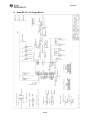
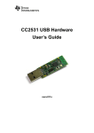
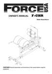
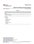
CC1110 & CC2510
Mini Development Kit
User’s Guide
SWRU236a
swru236a
Table of contents
1
INTRODUCTION ..........................................................................................................................3
2
ABOUT THIS MANUAL ..............................................................................................................4
3
ACRONYMS...................................................................................................................................5
4
MINI DEVELOPMENT KIT CONTENT ...................................................................................6
5
GETTING STARTED....................................................................................................................8
5.1
6
SETUP ........................................................................................................................................8
USING THE HARDWARE .........................................................................................................10
6.1
POWER SOURCES .....................................................................................................................10
6.1.1
Battery Power .................................................................................................................10
6.1.2
External Power Supply ...................................................................................................11
6.2
BUTTONS .................................................................................................................................11
6.3
LEDS ......................................................................................................................................11
6.4
DEBUG CONNECTOR (DEBUG) ............................................................................................11
6.5
I/O PIN CONNECTORS (INTIO)................................................................................................12
6.6
ANTENNA OPTIONS .................................................................................................................12
6.7
HARDWARE DEVELOPMENT ....................................................................................................13
7
USING SMARTRF STUDIO WITH SMARTRF CC1110/CC2510 TARGET BOARDS .....14
7.1
7.2
7.3
TESTING TX PARAMETERS ......................................................................................................17
TESTING RX PARAMETERS ......................................................................................................17
LINK AND RANGE TESTING ......................................................................................................17
8 USING SMARTRF PACKET SNIFFER WITH SMARTRF CC1110/CC2510 TARGET
BOARDS ...............................................................................................................................................19
9
SOFTWARE APPLICATION EXAMPLES .............................................................................21
9.1
RUNNING AND DEVELOPING SOFTWARE APPLICATION EXAMPLES .........................................21
10
FREQUENTLY ASKED QUESTIONS..................................................................................22
11
REFERENCES .........................................................................................................................23
12
DOCUMENT HISTORY .........................................................................................................24
A
SMARTRF CC1110 TARGET BOARD.....................................................................................25
B
SMARTRF CC2510 TARGET BOARD.....................................................................................26
2/26
swru236a
1
Introduction
Thank you for purchasing the CC1110 Mini Development Kit 868-915 MHz or the CC2510
Mini Development Kit.
The CC1110 and CC2510 are System-on-Chip (SoC) devices from Texas Instruments
designed for low power wireless applications. CC1110 operates in the sub-1 GHz unlicensed
ISM bands while the CC2510 operates in the 2.4 GHz unlicensed ISM bands. The CC1110
and CC2510 combine the excellent performance of the state-of-the-art CC1101 and CC2500
RF transceivers respectively with an industry-standard enhanced 8051 MCU, up to 32 kB of
in-system programmable flash memory and up to 4 kB of RAM, and many other powerful
features.
The CC1110 and CC2510 are highly suited for systems where very low power consumption is
required. This is ensured by several advanced low-power operating modes. The small 6x6
mm package further makes it suited for applications with size limitations.
The CC1110 and CC2510 mini development kits include all the necessary hardware in order
to evaluate, demonstrate, prototype and develop software targeting proprietary applications
requiring a sub-1 GHz or 2.4 GHz radio.
Make sure to subscribe to the Low-Power RF eNewsletter to receive information about
updates to documentation, new product releases and more. Sign up on the Texas
Instruments Low Power RF web site www.ti.com/lprf.
3/26
swru236a
2
About this Manual
This manual contains both tutorial and reference information regarding the hardware
components of both the CC1110 Mini Development Kit and the CC2510 Mini Development
Kit.
Chapter 4 briefly describes the content of this development kit and chapter 5 and 6 gives a
quick introduction to how to set-up and use the hardware. Chapter 7 describes how to use the
kit with SmartRF® Studio [7] and chapter 8 briefly shows how to use the kit hardware as
capture devices with the SmartRF Packet sniffer [8]. Chapter 9 mentions other software that
is available for the mini development kits. A troubleshooting guide can be found in chapter 10.
Chapter 11 provides a list of relevant documents and links. Appendix A and B contain the
schematics for the SmartRF CC1110 and SmartRF CC2510 target boards respectively. The
complete reference design for both the target boards are further available on the mini
development kit web pages on the TI web site, see [4] and [5].
The CC1110 Mini Development Kit 868-915 MHz Quick Start Guide [1] and the CC2510 Mini
Development Kit Quick Start Guide [2] are short tutorials on how to quickly and easy get
started with the two mini development kits and how to use the preprogrammed link test on the
kits. The CC1110 & CC2510 Mini DK Software Example User's Guide [3] describes the
source code and has more detailed documentation on the preprogrammed link test that
comes with the kit.
The CC Debugger User’s Guide [6] covers all the details regarding the CC Debugger tool that
comes with this kit. The user’s guides for the PC tools SmartRF Studio [7] and SmartRF Flash
Programmer [9] give details on the use of these PC tools. Relevant design notes and
application notes for the CC1110 and CC2510 mini development kits, and the CC1110 and
CC2510 datasheet and errata note can be in the device product folders ([14] and [15]). Also
visit the kit web pages [4] and [5] for additional information.
4/26
swru236a
3
Acronyms
DK
IC
ISM
I/O
kB
LED
LPRF
MCU
PCB
RAM
RF
RX
SoC
SPI
SRD
TI
TX
UART
USB
PCB
Development Kit
Integrated Circuit
Industrial, Scientific and Medical
Input/ Output
Kilo Byte (1024 byte)
Light Emitting Diode
Low Power RF
Micro Controller
Printed Circuit Board
Random Access Memory
Radio Frequency
Receive
System on Chip
Serial Peripheral Interface
Short Range Device
Texas Instruments
Transmit
Universal Asynchronous Receive Transmit
Universal Serial Bus
Printed Circuit Board
5/26
swru236a
4
Mini Development Kit Content
The CC1110 and CC2510 mini Development Kits include the necessary hardware and
software tools to allow quick testing of the CC1110 or CC2510 performance. They further
offer a complete platform to develop prototype RF systems.
•
Evaluate the CC1110/CC2510 right out of the box. The kits can be used for range
testing using the pre-programmed link test.
•
Prototype development. All I/Os from the CC1110 and CC2510 are available on pin
connectors and/or through holes on the PCB, allowing easy interconnection to other
devices or controllers and also easy debugging.
•
Together with the CC Debugger, the SmartRF CC1110/CC2510 target board can be
configured through SmartRF Studio [7] or programmed using SmartRF Flash
Programmer [9]. Debugging can be done using the IAR Embedded Workbench [10].
The CC1110 and CC2510 mini development kits contain:
• 2 x SmartRF CC1110 or SmartRF CC2510 target boards
• 1 x CC Debugger including the necessary cables and connector convertors
• 4 x AAA batteries
• CD with Evaluation version of the IAR EW8051
• Documentation
Figure 4-1 – CC1110 Mini Development Kit 868-915 MHz Content
Figure 4-2 – CC2510 Mini Development Kit Content
6/26
swru236a
SmartRF CC1110 Target Board
The SmartRF CC1110 target board contains
the RF IC, necessary external components,
battery holders, LEDs, and a PCB antenna.
The module is pre-programmed with a link
test for easy use. The board further includes
user I/Os and access to CC1110 peripherals.
•
•
•
•
•
•
CC1110 DEBUG interface
CC1110 SPI
CC1110 UART
2 Buttons
2 LEDs
General purpose I/Os
SmartRF CC2510 Target Board
The SmartRF CC2510 target board contains
the RF IC, necessary external components,
battery holders, LEDs, and a PCB antenna.
The module is pre-programmed with a link
test for easy use. The board further includes
user I/Os and access to CC2510 peripherals.
•
•
•
•
•
•
CC2510 DEBUG interface
CC2510 SPI
CC2510 UART
2 Buttons
2 LEDs
General purpose I/Os
CC Debugger
The CC Debugger enables programming
and debugging the flash of the CC1110/
CC2510. It connects to the PC via USB and
uses the DEBUG interface to communicate
with the radio. The PC Tools available for
these purposes are SmartRF Flash
Programmer [9] from Texas Instruments and
IAR Embedded Workbench for 8051 [10]
from IAR Systems. The CC Debugger also
allows the user to control and run tests on
the SmartRF CC1110/CC2510 target boards
using SmartRF Studio [7].
7/26
swru236a
5
5.1
Getting Started
Setup
The SmartRF CC1110/CC2510 target board is a complete standalone RF reference platform
with user interfaces and connections needed for development with the CC1110/CC2510.
It can be used both standalone (powered from batteries) or together with the CC Debugger
(for testing and debugging purposes) as shown in Figure 5-1 and Figure 5-2 respectively.
Figure 5-1 – SmartRF CC2510 target board standalone
Figure 5-2 – SmartRF CC2510 target board connected to the CC Debugger
The two SmartRF CC1110/CC2510 target boards in the mini development kit are identical
and come pre-programmed with a link test application. When running the out of the box link
test, the boards can be used standalone. The boards can then be powered from either the 2 x
1.5V AAA batteries that are included in this kit or an external regulated power source (not
included in this kit). The power source can be selected with the jumper on the power selection
connector P1 on the boards. Read more about this in section 6.1.
When not using the out of the box link test (i.e. the preprogrammed application) e.g. for RF
evaluation or software development, the SmartRF CC1110/CC2510 target board can be
connected to the CC Debugger. The SmartRF CC1110/CC2510 target board includes
interfaces for programming and debugging the CC1110/CC2510 via the small connector
marked “Debug”.
The boards further provide access to all the I/O signals from the CC1110/CC2510, two LEDs
and two push buttons.
8/26
swru236a
After assembling the hardware, there are several options for working with the CC1110 and
CC2510 devices:
•
Run the link test application that is preprogrammed on the CC1110’s/CC2510’s. The
CC1110 Mini Development Kit 868-915 MHz Quick Start Guide [1] or the CC2510
Mini Development Kit Quick Start Guide [2] included in the kits describes the
necessary steps to run this application.
•
Evaluate and explore the RF capabilities of the CC1110/CC2510 using SmartRF
Studio [7]. Chapter 7 provides the details how to do so.
•
Develop your own software for the CC1110/CC2510. Install IAR Embedded
Workbench for 8051 [10] and set up your first software project. Section 9.1 explains
how.
•
Develop your own hardware with the CC1110/CC2510. See section 6.7.
9/26
swru236a
6
Using the hardware
Figure 6-1 shows the main components of the board and outlines the main communication
buses. Please refer to Appendix A and B for the full schematics of the boards.
2 LEDs
2 Push Buttons
Batteries
CC1110/CC2510
GDIOs
SPI
UART
DEBUG connector
Figure 6-1 – The SmartRF CC1110/CC2510 target board architecture
6.1
Power Sources
There are several solutions for applying power to the SmartRF CC1110/CC2510 target
boards; batteries, external power or power from the CC Debugger. The desired power source
is selected with a jumper on the power selection connector P1.
Figure 6-2 – The power selection connector on the SmartRF CC1110 and the SmartRF
CC2510 target boards
All power sources are disconnected when no jumper short either pin 1-2 or 3-4 on the power
selection connector. The SmartRF CC1110/CC2510 target boards are reset by disconnecting
the power selection jumper, pressing either of the buttons and then reconnecting the power
selection jumper. The button must be pushed to ensure that the large capacitor on the power
line gets completely discharged; otherwise this could take minutes depending on the current
drawn by the board.
6.1.1
Battery Power
The SmartRF CC1110/CC2510 target boards include two battery solutions. They have battery
holders for both two AAA batteries; normal 1.5 V AAA can be used, and for a 3 V 2032 coin
cell battery on the reverse side of the PCB. The power selection jumper shall short circuit pin
10/26
swru236a
1 and 2 of the power selection connector P1 when using battery power. The jumper can
optionally be replaced with an Ampere meter for current measurements
Note that only one of the battery sources (AAA or coin cell) should be present in the battery
holders at the same time to avoid damaging the batteries.
The pre-programmed link test is optimized for making a robust link and is thus not power
optimized; see more in the CC1110 & CC2510 Mini DK Software Example User’s Guide [3].
For this reason, due to limitations of coin cell batteries, it is not recommended to run the
preprogrammed link test SW on a coin cell battery.
6.1.2
External Power Supply
The SmartRF CC1110/CC2510 target board can optionally be powered from the CC
Debugger or an external power supply. To power the board from the CC Debugger, the CC
Debugger must be connected to the DEBUG connector on the SmartRF CC1110/CC2520
target board, and the jumper must be placed between pin 3 and 4 on the power selection
connector P1. The board will be powered with 3.3 V when powered from the CC Debugger.
To power the board using an external power source, a voltage in the range from 2.0 V to 3.6
V must be applied to pin 3 on the power selection connector P1 or to pin 9 on the DEBUG
connector. Ground from the power supply must be connected to any of the GND pads on the
board. The jumper must be placed between pin 3 and 4 on the power selection connector P1.
The jumper can optionally be replaced with an Ampere meter for current measurements.
Make sure to only have one power source connected at the same time. Note that the voltage
from the external power supply must never exceed the maximum ratings for the CC1110/
CC2510 (-0.3 V to 3.9 V) to avoid damaging the chip.
6.2
Buttons
There are two buttons, MASTER (S1) and SLAVE (S2), on the SmartRF CC1110/ CC2510
target boards. The two buttons are connected to the SoC at pin P1.2 and P1.3 respectively.
Both the buttons are connected to I/O ports without any filtering. On the SmartRF CC1110
target boards, the signals from P1.2 and P1.3 are also available through the test points TP3
and TP6.
6.3
LEDs
There are 2 LEDs on the target boards, D1 (red) and D2 (green). The two LEDs are controlled
from the SoC through pin P1.1 and P1.0 respectively as these have LED driving capabilities.
On the SmartRF CC1110 target boards, these signals are also available through the test
points TP4 and TP5.
6.4
DEBUG Connector (DEBUG)
The SmartRF CC1110/CC2510 target boards contain a debug interface for easy
programming and debugging of the modules. The debug interface connector (DEBUG) pinout is shown in Table 1. Note that this connector also provides an SPI or UART interface to
the CC1110/CC2510 (connected to USART0, alternative 1, on the chip) in addition to the
DEBUG interface.
The DEBUG connector includes two VDD connections, one on pin 2 and one on pin 9. The
functions for these connections are different. Pin 2 VDD supplies voltage from the target
board to the signal level converter on the CC Debugger, making it possible to operate at
separate voltages internally on the Debugger and on the SmartRF CC1110/CC2510 target
board. This pin must always be connected when using the CC Debugger. Pin 9 VDD supplies
VDD (3.3 V) from the CC Debugger or from an external power supply.
11/26
swru236a
Signal name
Pin
Pin
Signal name
GND
1
2
VDD (local)
DC (Debug Clock)
3
4
DD (Debug Data)
CSn/ RT
5
6
SCLK/ CT
RESET_N
7
8
MOSI/ TX
VDD (external)
9
10
MISO/ RX
Table 1 – DEBUG connector pin-out
6.5
I/O Pin Connectors (INTIO)
The INTIO connector brings out the remaining I/O signals from the SoC, see Table 2 for pinout. The I/O signals are available through separate test points to provide easy access for
debugging or for connection to external devices.
Signal name
Pin
Pin
Signal name
GND
1
2
P1.7
P2.0
3
4
P1.6
P0.7
5
6
P1.5
P0.6
7
8
P1.4
P0.5
9
10
P0.0
P0.4
11
12
P0.1
P0.3
13
14
P0.2
Table 2 - I/O connector IOPIN pin-out
6.6
Antenna Options
The SmartRF CC1110 and the SmartRF CC2510 target boards both contain PCB antennas
for transmitting/ receiving the RF signals.
Figure 6-3 – The antennas on the SmartRF CC1110 and SmartRF CC2510 target boards
The PCB antenna can optionally be disconnected by turning the R1 resistor on SmartRF
CC1110 target board or the R2 resistor on the SmartRF CC2510 target board 90 degrees
from the PCB antenna position to a test point. By turning the R1/R2 resistor to the test point
12/26
swru236a
position, debugging of the RF signal can be performed or other antenna solutions can be
tested. This is explained in more details in section 7.1.
The antenna on the SmartRF CC1110 target board is highly directive, see more in DN024
[19]. For optimal range when using these boards, it is crucial to place the boards so that the
arrow in the silk print next to the antenna points upwards towards the sky or roof as seen in
Figure 6-4 below.
Figure 6-4 – Correct placement of the SmartRF CC1110 target boards for optimal PCB
antenna performance
Note that the PCB antenna lengths on the SmartRF CC1110 and SmartRF CC2510 target
boards are tuned for optimal performance with two AAA batteries present in the battery
holder. The SmartRF CC1110 target board is tuned for optimal performance in the 868 MHz
band while the SmartRF CC2510 target board is tuned for optimal performance in the 2.4
GHz band. The optimal antenna length for 915 MHz operation (still with the two AAA batteries
in the battery holder) is shown in the silk print on the SmartRF CC1110 target boards.
Removing the two AAA batteries from the battery holder on the board, encapsulating the
board etc. detunes the PCB antenna and thus alters the antenna performance. The detuning
can be compensated for by changing the length of the antenna or adding tuning components
just before the antenna. This is explained in more details in DN024 [19] for the SmartRF
CC1110 target board and AN043 [20] for the SmartRF CC2510 target board.
6.7
Hardware Development
When designing new hardware using the CC1110/CC2510, it is recommended to use either
the CC1110EM/CC2510EM or the SmartRF CC1110/CC2510 target boards as reference
designs. The full CC1110EM/CC2510EM or the SmartRF CC1110/CC2510 target board
reference design files can be downloaded from the CC1110/CC2510 product folder on the
web ([14]/[15]) or the CC1110/CC2510 Mini Development Kit website ([4]/[5]).
13/26
swru236a
7
Using SmartRF Studio with SmartRF CC1110/CC2510 Target Boards
RF testing on the mini development kit is best performed by using the PC tool SmartRF
Studio [7]. SmartRF Studio can be downloaded from www.ti.com/smartrfstudio. Follow the
instructions given in the SmartRF Studio User’s Guide [11] to install this tool. The installation
also installs the necessary drivers for the CC Debugger.
To use SmartRF Studio, the SmartRF CC1110/CC2510 target board must be connected to
the CC Debugger as shown in Figure 7-1. Decide which power source to use with the jumper
on P1 (see section 6.1). Connect the CC Debugger to the PC via USB.
Figure 7-1 – SmartRF CC2510 target board connected to CC Debugger
After starting SmartRF Studio and plugging the CC Debugger to the PC via USB, the window
shown in Figure 7-2 or Figure 7-3 will appear depending on which board you have. Make sure
you select the tab called SmartRF®05DK in the top part of the window. The connected
SmartRF CC1110 or SmartRF CC2510 target board will be listed as “CC1110 – new device”
or “CC2510 – new device” respectively. Double click on the new device item, and the window
shown in Figure 7-4 and Figure 7-5 will appear. This is the main control panel for the CC1110/
CC2510. In this window, settings can be changed, tests performed and registers adjusted.
It is highly recommended to use SmartRF Studio actively when finding the optimal RF and
register settings. The following paragraphs will describe how to use SmartRF Studio for
testing TX and RX performance and how to use the tool to send and receive packets.
14/26
swru236a
Figure 7-2 - Start window for the SmartRF CC1110 target board when starting SmartRF
Studio
Figure 7-3 - Start window for the SmartRF CC2510 target board when starting SmartRF
Studio
15/26
swru236a
Figure 7-4 - Control window for the SmartRF CC1110 target board from SmartRF Studio
Figure 7-5 - Control window for the SmartRF CC2510 target board from SmartRF Studio
16/26
swru236a
7.1
Testing TX Parameters
To investigate the TX performance of the CC1110 and CC2510 mini development kits with
the SmartRF Studio, the RF measurement equipment may be connected to the target board
in three different ways:
•
•
•
Connect an appropriate antenna to a spectrum analyzer and make sure that R1 on
the SmartRF CC1110 target board or R2 on the SmartRF CC2510 target board is
mounted in the PCB antenna direction. Use the “Simple TX” test mode in SmartRF
Studio and set the desired parameters.
Solder a semi rigid cable to test point T2 on the SmartRF CC1110 target board or T3
on the SmartRF CC2510 target board and turn the R1/R2 resistor from the PCB
antenna position to the test point position, see more in section 6.6. Connect a 50
Ohm coaxial cable from the spectrum analyzer to the semi rigid cable and use the
“Simple TX” test mode in SmartRF Studio to set the desired parameters. This is
illustrated in Figure 7-6.
Turn the R1/R2 resistor (SmartRF CC1110/ SmartRF CC2510 target board
respectively) from the PCB antenna position to the test point position and connect the
test point to the desired antenna. Connect an appropriate antenna to the spectrum
analyzer. Use the “Simple TX” test mode in SmartRF Studio and set the desired
parameters.
Figure 7-6 - Output power measurement
When testing RF performance, make sure that the spectrum analyzer is calibrated. If
possible, check it against a calibrated instrument such as an RF signal generator. Uncalibrated spectrum analyzers can display errors of several dBs. Also be aware of the
Resolution Band Width (RBW) setting on the spectrum analyzer. By using good-quality RF
cabling, the loss in the cabling should be negligible. When antennas are used in the
measurements, the “Max Hold” option on the spectrum analyzer should be used.
7.2
Testing RX Parameters
For information regarding sensitivity measurement, refer to DN002 [17]. For conducted
measurements, the kit should be set up with a semi rigid cable as explained in section 7.1. By
adding a jammer (a third node that generates either noise on the same channel or a strong
signal on an adjacent channel), it is also possible to evaluate co-channel rejection and
selectivity/blocking performance.
7.3
Link and Range testing
To test the link quality and range using the CC1110/CC250 mini development kit, you have
several options. You can run “Packet TX” and “Packet RX” tests from SmartRF Studio or you
can use the SmartRF CC1110/CC2510 target boards stand-alone using the preprogrammed
link test.
17/26
swru236a
When using the “Packet TX” and “Packet RX” tests from SmartRF Studio, the two target
boards must be connected to the PC through separate CC Debuggers. Note that the kit only
includes one CC Debugger. To test the link, follow the procedure given below.
•
•
•
•
•
•
Double click on both of the devices in the device list in SmartRF Studio (Figure 7-2 or
Figure 7-3), opening two windows, and giving control of the two radios at the same
time.
Select one device to be the transmitter, by selecting the “Packet TX” tab shown in the
lower middle of Figure 7-4 and Figure 7-5.
On the other device (the receiver), select the “Packet RX” tab.
Set up basic test parameters and press the “Start packet RX” button.
Now you can start transmission by pressing the “Start packet TX” button for the
transmitter.
The status window, in the lower right corner of the device control panel, will show the
number of packets sent on the transmitter side and the number of received on the
receiver side.
To perform practical range testing with the preprogrammed link test application on the
SmartRF CC1110/CC2510 target boards, follow the directions given in the CC1110 Mini
Development Kit 868-915 MHz Quick Start Guide [1] or the CC2510 Mini Development Kit
Quick Start Guide [2]. Note that several parameters like the antenna, register settings and the
environment will affect the range. For more information regarding range testing, please refer
to DN018 [18] and section 6.6.
18/26
swru236a
8
Using SmartRF Packet Sniffer with SmartRF CC1110/CC2510 Target
Boards
You can use the SmartRF CC1110/CC2510 target boards to capture radio packets with the
SmartRF Packet Sniffer [8].
When the board is connected to the CC Debugger, as depicted in Figure 5-2, you can start
the Packet Sniffer.
Figure 8-1 - Start up window of the SmartRF Packet Sniffer
Select and appropriate software protocol (Generic or SimpliciTI) and click the Start button.
Figure 8-2 - Packet Sniffer Setup Panel
In the setup panel of the sniffer, you will see the CC Debugger connected to, in this case, the
CC1110 on the SmartRF CC1110 target board. Also note the “Sniffer communication
interface” radio button in the lower right corner of the window. Please make sure USART0 is
selected.
19/26
swru236a
Figure 8-3 - Packet Sniffer Radio Settings
Before starting, it is necessary to select the radio settings to use for correct packet capturing.
These are the RF register settings which will be written to the CC1110 before it starts to
receive packets. The register settings can be exported from SmartRF Studio in a format that
the SmartRF Packet Sniffer is capable of understanding. Use the “Code export” option in
SmartRF Studio and select the “Packet Sniffer Template”. Save the exported settings in a file
(with extension .prs) and the Sniffer will now be able to open this file and use these settings.
Figure 8-4 - Exporting register settings from SmartRF Studio to the Packet Sniffer
You can now start to capture packets by pressing the “Play” button in the sniffer. Please refer
to the SmartRF Packet Sniffer User Manual [13] for further details.
20/26
swru236a
9
Software Application Examples
The SmartRF CC1110/CC2510 target boards come pre-programmed with a link test
application which makes it possible to e.g. perform simple range testing out of the box. For
more details regarding how to run the pre-programmed link test, see the CC1110 Mini
Development Kit 868-915 MHz Quick Start Guide [1], the CC2510 Mini Development Kit
Quick Start Guide [2] and the CC1110 & CC2510 Mini DK Software Example User’s Guide
[3]. Refer to the CC Debugger [6] and SmartRF Flash Programmer [12] User’s Guides for
more information regarding these tools.
9.1
Running and Developing Software Application Examples
In order to program and debug the SmartRF CC1110/CC2510 target board with proprietary
application software, connect the CC Debugger to the DEBUG interface on the SmartRF
CC1110/CC2510 target board. Use SmartRF Flash Programmer [9] to program the
CC1110/CC2510 or use IAR Embedded Workbench [10] to download and debug.
All the kit software examples available from TI are provided as source code and are written
for the IAR Embedded Workbench for 8051. It is necessary to have the Embedded
Workbench installed to be able to compile or debug the source code. An evaluation version of
IAR Embedded Workbench is included in this CC1110/CC2510 Mini Development Kit (CD).
To ensure that you get the newest version of the IAR Embedded Workbench Evaluation
Edition, we recommend that you download it from the IAR web page www.iar.com/ew8051.
From the IAR web site, a free kick start edition of the IAR Embedded Workbench is also
available. The kick start edition of IAR Embedded Workbench is code size limited, but it is still
a fully functional and integrated development environment and it is ideal for creating small
applications or for getting started fast on a new project. The only requirement is that you
register to get a license key. The CC1110 Mini Development Kit 868-915 MHz and CC2510
Mini Development Kit benefit from an extended code size limit in the IAR Embedded
Workbench for 8051 version 7.51A and above. A 16kb “SimpliciTI-mode” will be activated by
passing the command line option ‘--ks_version’ to the linker (project->options->linker->extra
options). In “SimpliciTI-mode”, the simulator will still have a 4kb code size limit, so a
development kit with CC2510Fx, CC1110Fx or CC2430Fx is needed benefit from the extra
code size.
Both the evaluation and the kick start edition of IAR Embedded Workbench include project
manager, editor, C/C++ compiler, assembler, linker, librarian and debugger tools. User
manuals and additional information is found on the IAR web page www.iar.com. Make sure to
choose the version for the 8051 processor family/core, not the version for the Texas
Instruments MSP430 processor family/core.
21/26
swru236a
10 Frequently Asked Questions
Q1
What kind of coin cell batteries can I use?
A1
Normal 3 V 2032 coin cell batteries may be used to power the SmartRF
CC1110/CC2510 target boards.
Q2
Nothing happens when I power up the board.
A2
Make sure that the jumper on the P1 header on the SmartRF CC1110/CC2510 board is
set in the correct position. Please refer to section 6.1 for correct jumper setting.
Q3
How can I measure the current consumption of the radio on the SmartRF
CC1110/CC2510 boards?
A3
The easiest way to measure current consumption of the chip in various modes is to
connect the board directly to the CC Debugger and disconnect everything on the board
that consumes power. Replace the power source selection jumper on P1 with the
ampere meter. Use SmartRF Studio to set the radio in different modes (RX, TX, etc.).
Q4
The two boards will not establish a link/ are loosing packets even though the boards are
not far apart.
A4
Make sure that the boards are not saturated. Place the boards a couple of meters apart
and try again. Take care when moving the boards closer together to avoid saturation.
Q5
The two LEDs on the SmartRF CC1110/CC2510 boards do not come on after reset of
the board when re-adding the power selection jumper and running the pre-programmed
link test.
A5
Reset the board once more and be sure to press one of the buttons while the power
selection jumper is disconnected. This will ensure that the large capacitor on the power
line is discharged.
22/26
swru236a
11 References
[1]
CC1110 Mini Development Kit 868-915 MHz Quick Start Guide
http://www.ti.com/lit/swru234
[2]
CC2510 Mini Development Kit Quick Start Guide
http://www.ti.com/lit/swru235
[3]
CC1110 & CC2510 Mini DK Software Example User’s Guide
http://www.ti.com/lit/swru237
[4]
CC1110 Mini Development Kit 868-915 MHz website
http://focus.ti.com/docs/toolsw/folders/print/cc1110dk-mini-868.html
[5]
CC2510 Mini Development Kit website
http://focus.ti.com/docs/toolsw/folders/print/cc2510dk-mini.html
[6]
CC Debugger User’s Guide
http://www.ti.com/lit/swru197
[7]
SmartRF Studio
http://www.ti.com/smartrfstudio
[8]
SmartRF Packet Sniffer
http://focus.ti.com/docs/toolsw/folders/print/packet-sniffer.html
[9]
SmartRF Flash Programmer
http://focus.ti.com/docs/toolsw/folders/print/flash-programmer.html
[10] IAR Embedded Workbench for 8051
http://www.iar.com/ew8051
[11] SmartRF Studio User’s Guide
http://www.ti.com/lit/pdf/swru070
[12] SmartRF Flash Programmer User’s Guide
http://www.ti.com/lit/pdf/swru069
[13] SmartRF Packet Sniffer User Manual
http://www.ti.com/lit/pdf/swru187
[14] CC1110 Product Folder
http://focus.ti.com/docs/prod/folders/print/cc1110f32.html
[15] CC2510 Product Folder
http://focus.ti.com/docs/prod/folders/print/cc2510f32.html
[16] CC1110, CC2510 Basic Software Examples
http://www.ti.com/lit/zip/swrc117
[17] DN002 - Practical Sensitivity Testing
http://www.ti.com/lit/swra097
[18] DN018 - Range Measurements in an Open Field Environment
http://www.ti.com/lit/swra169
[19] DN024 – 868 MHz, 915_MHz and 955 MHz Monopole PCB Antenna
http://www.ti.com/lit/swra227
[20] AN043 – Small Size 2.4 GHz PCB Antenna
http://www.ti.com/lit/swra117
23/26
swru236a
12 Document history
Revision
Date
swru236a
2009-11-17
swru236
2009-07-17
Description/Changes
Updated links, added information regarding how to extend the code size limited IAR
Embedded Workbench for 8051 version 7.51A and above so that it can be used with
SimpliciTI.
First revision.
24/26
swru236a
A
SmartRF CC1110 Target Board
25/26
swru236a
B
SmartRF CC2510 Target Board
26/26
IMPORTANT NOTICE
Texas Instruments Incorporated and its subsidiaries (TI) reserve the right to make corrections, modifications, enhancements, improvements,
and other changes to its products and services at any time and to discontinue any product or service without notice. Customers should
obtain the latest relevant information before placing orders and should verify that such information is current and complete. All products are
sold subject to TI’s terms and conditions of sale supplied at the time of order acknowledgment.
TI warrants performance of its hardware products to the specifications applicable at the time of sale in accordance with TI’s standard
warranty. Testing and other quality control techniques are used to the extent TI deems necessary to support this warranty. Except where
mandated by government requirements, testing of all parameters of each product is not necessarily performed.
TI assumes no liability for applications assistance or customer product design. Customers are responsible for their products and
applications using TI components. To minimize the risks associated with customer products and applications, customers should provide
adequate design and operating safeguards.
TI does not warrant or represent that any license, either express or implied, is granted under any TI patent right, copyright, mask work right,
or other TI intellectual property right relating to any combination, machine, or process in which TI products or services are used. Information
published by TI regarding third-party products or services does not constitute a license from TI to use such products or services or a
warranty or endorsement thereof. Use of such information may require a license from a third party under the patents or other intellectual
property of the third party, or a license from TI under the patents or other intellectual property of TI.
Reproduction of TI information in TI data books or data sheets is permissible only if reproduction is without alteration and is accompanied
by all associated warranties, conditions, limitations, and notices. Reproduction of this information with alteration is an unfair and deceptive
business practice. TI is not responsible or liable for such altered documentation. Information of third parties may be subject to additional
restrictions.
Resale of TI products or services with statements different from or beyond the parameters stated by TI for that product or service voids all
express and any implied warranties for the associated TI product or service and is an unfair and deceptive business practice. TI is not
responsible or liable for any such statements.
TI products are not authorized for use in safety-critical applications (such as life support) where a failure of the TI product would reasonably
be expected to cause severe personal injury or death, unless officers of the parties have executed an agreement specifically governing
such use. Buyers represent that they have all necessary expertise in the safety and regulatory ramifications of their applications, and
acknowledge and agree that they are solely responsible for all legal, regulatory and safety-related requirements concerning their products
and any use of TI products in such safety-critical applications, notwithstanding any applications-related information or support that may be
provided by TI. Further, Buyers must fully indemnify TI and its representatives against any damages arising out of the use of TI products in
such safety-critical applications.
TI products are neither designed nor intended for use in military/aerospace applications or environments unless the TI products are
specifically designated by TI as military-grade or "enhanced plastic." Only products designated by TI as military-grade meet military
specifications. Buyers acknowledge and agree that any such use of TI products which TI has not designated as military-grade is solely at
the Buyer's risk, and that they are solely responsible for compliance with all legal and regulatory requirements in connection with such use.
TI products are neither designed nor intended for use in automotive applications or environments unless the specific TI products are
designated by TI as compliant with ISO/TS 16949 requirements. Buyers acknowledge and agree that, if they use any non-designated
products in automotive applications, TI will not be responsible for any failure to meet such requirements.
Following are URLs where you can obtain information on other Texas Instruments products and application solutions:
Products
Amplifiers
Data Converters
DLP® Products
DSP
Clocks and Timers
Interface
Logic
Power Mgmt
Microcontrollers
RFID
RF/IF and ZigBee® Solutions
amplifier.ti.com
dataconverter.ti.com
www.dlp.com
dsp.ti.com
www.ti.com/clocks
interface.ti.com
logic.ti.com
power.ti.com
microcontroller.ti.com
www.ti-rfid.com
www.ti.com/lprf
Applications
Audio
Automotive
Broadband
Digital Control
Medical
Military
Optical Networking
Security
Telephony
Video & Imaging
Wireless
www.ti.com/audio
www.ti.com/automotive
www.ti.com/broadband
www.ti.com/digitalcontrol
www.ti.com/medical
www.ti.com/military
www.ti.com/opticalnetwork
www.ti.com/security
www.ti.com/telephony
www.ti.com/video
www.ti.com/wireless
Mailing Address: Texas Instruments, Post Office Box 655303, Dallas, Texas 75265
Copyright © 2009, Texas Instruments Incorporated
Mouser Electronics
Authorized Distributor
Click to View Pricing, Inventory, Delivery & Lifecycle Information:
Texas Instruments:
CC2510DK-MINI