1
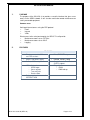
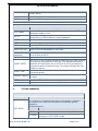
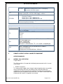
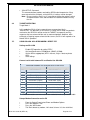
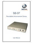
SS-81SA
User Manual
SS-81SA USER MANUAL
REVISION HISTORY
Revision 01
Original document
15 JULY 2009
CONTENTS
1.
PURPOSE ............................................................................................. 3
2.
FEATURES ........................................................................................... 3
3.
DESCRIPTION OF FRONT PANEL ...................................................... 4
4.
DESCRIPTION OF REAR PANEL ......................................................... 4
5.
APPLICATIONS .................................................................................... 5
6.
GETTING STARTED ............................................................................. 6
7.
COMMANDS ......................................................................................... 7
8.
TESTING COMMANDS ......................................................................... 8
9.
9.1
9.2
REMOTE ACCESS TO SERIAL CONNECTED EQUIPMENT ............... 9
NORMAL SS-81 OPERATION .............................................................. 9
TARGET OPERATION ........................................................................ 10
10.
USING SS-81SA AS A GPRS MODEM - DIRECT PPP....................... 10
11.
GETTING IMEI NUMBER AND OTHER INFO ..................................... 11
12.
CONTACT DETAILS ........................................................................... 12
DOC. NO: SS-81SA (REV. 01)
Page 2 of 12
SS-81SA USER MANUAL
1.
PURPOSE
The purpose of the SS-81SA is to provide a versatile interface that gives users
access to the GPRS network. It can also be used to do remote maintenance on
serially connected equipment.
Common uses:
Serial port internet access using the PPP protocol
•
Email
•
Internet
•
VPNs
Direct access to the serial port remotely via GPRS. This will provide
•
Maintenance access to an FCT Mux
•
Maintenance access to an SS-87
•
Logging
2.
FEATURES
FEATURES
•
Direct access so that PCs can
use PPP sessions
•
Direct TARGET setup
•
Single 5 volt power supply
•
Remote TARGET setup
•
Remote SS-81 setup
•
Simple Network Time Protocol
(SNTP) support
•
LED indicators for
o GPRS logon
o Server contact
o Transmit Data
o Receive Data
•
Diagnostics
o PING
o DNS look up
•
Push operation allows use of
INTERNET APN
DOC. NO: SS-81SA (REV. 01)
Page 3 of 12
SS-81SA USER MANUAL
3.
DESCRIPTION OF FRONT PANEL
Front Panel
LED INDICATORS
LED INDICATORS
PWR
F1
Indicates that the unit is supplied with a mains voltage
Auxiliary function Indicator (not implemented)
PORT 1 HS Indicates Handshaking on the specific Port
&
TX Indicates transmission to device connected at Port0 or Port1
PORT 0 RX Indicates Data reception from Port0 or Port1
RX Indicates that data is being received from the GSM module
GPRS
TX Indicates that data is being sent to the GSM module
SVR Indicates that contact has been established with the server
NET Indicates that the unit is logged on to the GPRS network.
4.
DESCRIPTION OF REAR PANEL
Rear panel
•
SMA ANTENNA CONNECTOR
•
SERIAL PORTS
PORT 0
PORT 1
9 way ‘D’ type MALE
9 way ‘D’ type FEMALE
Pi Description
n
Pin Description
2 Receive from device.
2 Transmit to device
3 Transmit to device
3 Receive from device.
4 Handshake to Port 0 device.
4 Handshake from PC
5 Common ground signal.
5 Common ground signal.
6
Handshake from Port 0
device.
DOC. NO: SS-81SA (REV. 01)
6 Handshake to device.
Page 4 of 12
SS-81SA USER MANUAL
•
5.
POWER SUPPLY - External
o External 12 volt power supply (centre pin positive)
APPLICATIONS
BASIC SETUP
Remote access to serially connected equipment. (Etc. FCT Mux)
Connecting to the Internet using PPP protocol.
DOC. NO: SS-81SA (REV. 01)
Page 5 of 12
SS-81SA USER MANUAL
6.
GETTING STARTED
Preparing the SIM card
Some SIM cards require initialising for proper operation.
•
To initialise the SIM card follow the following steps:
•
Place SIM card in cellular phone
•
Enter PIN (if required)
•
Request and accept MMS and Data settings
•
Reply to SMS messages from Network if Network requests a reply.
•
Accept more settings if required
•
Make a ‘missed’ call to a regular cellular phone.
•
Remove PIN request if no security on SIM is required.
Note:
If the pin code is required use SIMPIN command.
•
Put SIM card in the slot provided on the SS-81SA
GPRS SETUP
•
•
•
•
•
•
•
•
•
•
Connect a serial cable between PC and Port1 of the SS-81SA.
Use a coms package like HyperTerminal to connect to the SS-81SA.
o Baud Rate : 19200
o Parity : None
o Stop Bits : One
o Flow Control: None
Set the buffer name – Make sure it is unique and 8 characters long.
Set the Host – either to an IP address or an internet name.
Ensure the Port and CmdPort are both 1122
If a private APN is used, set the username and password
Check that the Time Server is set
Set the interval to 90
SAVE the settings
RESET the GPRS module (using ‘RESET’ command)
EXAMPLE OF COMMANDS
bufid SS81GPRS
host sstelecoms.pointclark.net
port 1122
cmdport 1122
timesvr time-a.nist.gov
interval 90
save
reset
DOC. NO: SS-81SA (REV. 01)
Page 6 of 12
SS-81SA USER MANUAL
7.
COMMANDS
COMMAND TABLE
Command
Description
Sets an alternate IP address for the DNS server.
When this is set (i.e. not equal to 0.0.0.0) then it will override all other DNS
ALTDNS <a.b.c.d>
settings. This address would normally be obtained from the service provider
or network operator.
APN <apn>
This is the Access Point Name used by the particular network or it can be a
private APN. Normally Vodacom & MTN use 'internet' and Virgin uses 'vdata'.
AT <cmd>
Will send <cmd> to the GPRS modem.
BUFID
<BuffName>
An 8 character field (it will be padded if less than 8 characters are entered)
CMDPORT <pppp> The port from which remote commands are accepted. Default value is 1122
Turns on (1) or off (0) diagnostic output. The following values can also be
used.
Value
DIAG <n>
Diagnostic function of code
01
Outputs the PPP messages for debugging of the PPP state
machine.
02
Outputs the GSM engine control messaging for debug of the GSM
engine state machine.
04
Outputs target message for diagnostic purposes.
08
Outputs DNS diagnostic messages.
The command parameters should be the sum of the options desired
expressed in Hex Decimal. I.e. DIAG 0F will turn on all the current options.
DISP
Displays the current settings on the unit
This setting will provide DNS options as listed below:
Value
DNSOPT <n>
Option
0
Automatic selection
1
Always use DNS 1
2
Always use DNS 2
Note:
The Automatic option will select the other DNS address if the currently
selected address fails. This toggles between DNS 1 and DNS 2 as provided
by the network operator or service provider. Changeover will take place when
an Answer type message was not received in time.
HANGUP
Stops GPRS operation
HOST <address>
This is the IP address or the FQDN of the logging server. If it is an FQDN,
the SS-81 will perform a DNS search to determine the IP address
IMEI
Outputs the IMEI number of the GPRS module
INTERVAL <nnn>
The time in seconds between polling the server when no data transfer is
taking place. Recommended setting is between 60 & 120. This allows the
'NATTED' address to remain in place.
LBAUD <baudrate> This is the 'buffer' or logging input baud rate. Can be set from 2400 to
DOC. NO: SS-81SA (REV. 01)
Page 7 of 12
SS-81SA USER MANUAL
115200. For TARGET mode operation it should be set to the baud rate of the
TARGET device.
LOAD
Restore the settings from non-volatile memory.
PASW
If a private APN is used a password may be required
COMMAND TABLE
Command
Description
PORT <pppp>
This is the IP port number that the SS-81 will address at the host. The
default port number is 1122.
PPP <n>
Enables (1) direct access after Network Logon. Used when the SS-81 is to
be operated as a GPRS module on external equipment.
RESET
Closes the GPRS session and restarts the SS-81 firmware.
SAVE
Saves the settings to non-volatile memory.
SCID
Outputs the SIM card ID.
SIMPIN <Sim Pin>
Sets the PIN that will be supplied to the SIM (if requested). This field is
numeric and should be between 4 and 8 digits.
TARGET
<command>
This sends the text <command> to the device on the Local Port. This may
be an SS-83 or an SS-76.
TARGET MODE <n> Enables (1) or Disables (0) semi transparent target based operation.
TARGET SETUP
Sets the SS-81 into a 'through connection mode' where the setup serial port
is transparently connected to the 'data' port (That would be connected to
some form of Target Device such as an SS-83 or SS-76) and allows the
Target device to be set up from this port. This mode will timeout after 120
seconds of inactivity.
TARGET TIME
Enables (1) or Disables (0) the setting of the Target time upon successful
Time Server queries.
TIMESVR <address>
A suitable time server. Either IP address or FQDN. The default is 'timea.nist.gov'
USER <username>
If a private APN is used a username may be required.
VER
Displays the firmware Version Number.
8.
TESTING COMMANDS
TESTING COMMAND TABLE
Command
Description
This command is used when direct access to the module is needed. In
this mode one can check the airtime balance and do other general
diagnostics.
Related commands:
TEST GPRS 1
Command
Description
ATD*101#; This will retrieve the airtime balance on Virgin Mobile
AT^SMSO
DOC. NO: SS-81SA (REV. 01)
This causes the GSM engine to power down, allowing the
exiting on the TEST GPRS 1 mode.
Page 8 of 12
SS-81SA USER MANUAL
Displays the signal strength. In fact any of the MC-55
commands can be given as there is a completely
transparent link to the module.
AT+CSQ
Displays the voltages relating to the GSM engine e.g.:
Voltages: GSM VDD = 2871mV, GSM Supply = 4101mV
VOLT
TESTMEM
Tests the 512K RAM that is fitted to the SS-81.
Executing TestMem
Memtest part 1: addr 80000 data 55
Memtest part 2: addr 80000 data 00 e: 00
If different results are obtained it suggests a memory fault. Note: This test
will erase everything in memory.
TESTING COMMAND TABLE
Command
Description
This will display the state of the 'input' handshaking line on the serial
ports in a small table.
RTS
The format is PORT.PIN = STATE
RTS Lines:
0.6 = 0
1.7 = 1
1.4 = 1
DNS
This command is used to find out the IPV4 address from an FQDN
DNS >www.google.com<
Options:- 8180, ID 305
Name: www.google.com
Returned IP = 216.239.59.103, TTL = 121 seconds accepted by #0
PING
Ping will test the path and response time to a host. It requires an IPV4
address. Subsequent 'pings' can be without an IP address.
Pinging 216.239.59.103
Ping reply from 216.239.59.103 time = 910 msec
9.
REMOTE ACCESS TO SERIAL CONNECTED EQUIPMENT
OPERATION MODES
9.1
NORMAL SS-81 OPERATION
Target mode 0
The SS-81 modules will respond to the following two commands while in normal
SS-81 mode.
• ‘DIRECT’ Command
This command will enable a 'pass through' mode of operation where any packets
that are received by GPRS are sent directly to the serial port without any
modification. Any data received on the serial port is coalesced using the Nagle
algorithm and send as packets on the GPRS link. This mode is time limited. It will
timeout after 90 seconds if no packets are received.
DOC. NO: SS-81SA (REV. 01)
Page 9 of 12
SS-81SA USER MANUAL
• ‘SS81SETUP’ Command
This command allows packets received by GPRS to be interpreted as if they
were entered at the serial port, so that the SS-81 settings can be changed.
Note: Be very careful using this as it is possible to change the settings so that
all communication is lost and cannot be re-established without visiting
the site.
9.2
TARGET OPERATION
Target Mode 1
In this mode the SS-81 will only respond to one command and that is
'SS81SETUP'. The behaviour is the same as in normal SS-81 mode. Any packets
received on the GPRS link will be sent to the TARGET transparently and any
responses that are returned will be sent as coalesced packets. However, while
waiting for a Greeting response from the Host server, the SS-81 will respond as for
Normal SS-81 Operation.
10.
USING SS-81SA AS A GPRS MODEM - DIRECT PPP
Settings on SS-81-SA
Enable PPP operation by setting 'PPP 1'
Set Local Baud rate to 115200 baud. (LBAUD 115200)
Set the APN as appropriate (MTN = internet, Virgin = vdata or private
APN)
Save settings
•
•
•
•
Connect serial cable between PC and Port0 of the SS-81SA
Connections between PC Serial port & SS-81-SA Port 0
SS-81-SA (DB9 Female)
PC Serial Port (DB9 Female)
PIN
DESCRIPTIONS
DESCRIPTIONS
PIN
1
No Connection (DCD)
No Connection (DCD)
1
2
Transmit (Input)
Transmit (Output)
3
3
Receive (Output)
Receive (Input)
2
4
Handshake (Output)
Handshake (Input)
8
5
Ground - Common
5
6
Handshake (Input)
Handshake (Output)
7
7
Handshake (Output)**
Handshake (Input)
6
8
Handshake (Input)**
Handshake (Output)
4
9
No Connection
No Connection
9
**These connections are not used, but are needed to make a symmetrical cable
Setup a Modem Connection on the PC
•
•
•
•
From the Control Panel select Phone and Modem Options
Press the 'Modems' TAB
Press the 'ADD' button
Tick 'Don't detect my modem; I will select it from a list.' then click Next
DOC. NO: SS-81SA (REV. 01)
Page 10 of 12
SS-81SA USER MANUAL
Under Manufacturer select (Standard Modem Types)
Under Models select ‘Standard 33600 bps Modem’ then click Next
Choose the com port that you want to use it on and click Next
Click Finish
The chosen modem should now be displayed. Close Phone and modem options
by clicking the 'OK' button.
•
•
•
•
Set up a Network connection on the PC
•
•
•
•
•
•
•
•
•
Open Network Connections.
Click on ‘Create New Connection’ to open Wizard.
Select 'Connect to the Internet' and click Next.
Select 'Set up my connection manually' and click Next.
Select 'Connect using a dial-up modem' and click Next.
Choose the modem shown that was set up earlier and click Next (Make
sure all the others are 'Un-Checked').
Type in a name such as 'SS-81 GPRS' then click Next.
Type in *99***1# for the phone number then click Next.
Leave the Username and Password blank unless using a private APN then
click Next.
To prevent all internet traffic from routing out via this link:
•
•
•
•
•
11.
Open the ‘Properties’ of the dial up connection.
Select 'Networking' tab.
Select Internet Protocol -> Properties
Select 'Advanced'
Make sure that the 'Use default gateway on remote network' is UN-ticked.
GETTING IMEI NUMBER AND OTHER INFO
S/W version '2.01' and above
•
•
Type in the command IMEI
Type in the command SCID for SIM card ID.
DOC. NO: SS-81SA (REV. 01)
Page 11 of 12
SS-81SA USER MANUAL
12.
CONTACT DETAILS
Office:
23 Botha Avenue
Lyttelton Manor
Pretoria, Gauteng
South Africa
Tel: +27 12 664 4644
Fax:+27 86 614 5625
E-mail: [email protected]
Postal address:
Postnet Suite 48
Private Bag x 1015
Lyttelton, 0140
Pretoria, Gauteng
South Africa
Sales Support:
E-mail: [email protected]
United Kingdom
E-mail: [email protected]
Technical Support:
E-mail: [email protected]
DOC. NO: SS-81SA (REV. 01)
Page 12 of 12