1
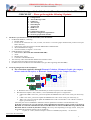
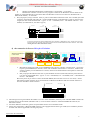
HIROLINK SMM
SERVICE MANUAL
English
Italian
cod. 272399 - Rev. 17.07.2003
English
HIROLINK SMM - SERVICE MANUAL
Package Checklist
Carefully unpack the contents of the package and verify them against the checklist given below.
þ
Hirolink SMM
þ
Cable for the connection between the Hirolink SMM to the GSM modem
þ
AC power adapter
þ
Connectivity CD-ROM with the Service Manual (Installation & Reference Guide)
þ
Technical Checklist (also in Appendix to the Manual – and available in internet www.connectivity.it in
“Supervision Systems” – “Hirolink SMM”- in the documentation - where it is constantly updated)
Please inform your dealer immediately should there be any wrong, missing or damaged part.
If possible, retain the carton, including the original packing materials. Use them again to repack the unit in case
there is a need to return it for repair.
Not included in the Hirolink SMM package but necessary for the Hirolink SMM system are:
Ø
the GSM modem (Wavecom 900-1800 Mhz) kit, with its antenna and AC power adapter (please always
verify with Our company what models have been tested as compatible with Hirolink SMM)
Ø
the SIM-card (voice & data, able to send and receive SMS) to insert into the GSM modem
2
cod. 272399 - Rev. 17.07.2003
English
HIROLINK SMM - SERVICE MANUAL
About this Guide
This guide is designed both for the installer and the user. It describes how to install and operate the Hirolink
SMM. Other information not included in this manual can be found in www.connectivity.it web page.
This manual covers the following topics:
Chapter 1: - Product Overview
Brief description of Hirolink SMM and a summary of its important features and specifications.
Chapter 2: - Installing the System
Installing the Hirolink SMM and making the proper connections.
Chapter 3: - Configuring the system
Configuration of the Hirolink SMM in order to implement the desired communication system. Configuration of
the other devices connected to Hirolink SMM.
Detailed description of the commands, indicators and connectors on Hirolink SMM and of the jumpers inside the
Hirolink SMM.
Appendix A: - Technical Checklist
A checklist of the issues and some practical guidelines on how to proceed with an installation
cod. 272399 - Rev. 17.07.2003
3
English
HIROLINK SMM - SERVICE MANUAL
Contents:
Package Checklist __________________________________________________________ 2
About this Guide ___________________________________________________________ 3
Contents: _________________________________________________________________ 4
Chapter 1: Product Overview _________________________________________________ 5
Basic Features __________________________________________________________________5
Short Messages Service Description ________________________________________________5
Chapter 2: Installing the System ______________________________________________ 8
Pre-Installation Requirements _____________________________________________________8
Connecting the Hirolink SMM_____________________________________________________8
Chapter 3: Configuring the system ___________________________________________ 12
Jumper settings on Hirolink SMM ________________________________________________12
Setting the Hiromatics___________________________________________________________12
Configuring the Hirolink SMM & SIM Card________________________________________12
Configuring the GSM modem ____________________________________________________13
Appendix A: Technical Checklist _____________________________________________ 13
4
cod. 272399 - Rev. 17.07.2003
English
HIROLINK SMM - SERVICE MANUAL
Chapter 1: Product Overview
The Hirolink SMM (Short Message Manager) is the communication manager that enables (in combination with a
GSM modem) the units to send SMS messages to GSM receivers. Its use is suitable for service purposes, to keep
up to four different users informed about the alarms occurring to the air conditioning units. The users must be
provided with a GSM mobile phone with a subscription to the SMS service. The SMSs can also be received by a
PC if connected to a GSM modem with SIM-card and equipped with the SMS collector software, called SMM
Server.
Basic Features
n
Up to 40 (forty) different SMS-messages
n
Customisable SMS-messages
n
Up to 100 (one hundred) characters per message
n
Messages can be sent to up to 4 GSM users
n
Capability to forward the incoming messages from one GSM user to the other
n
Capability to send “alive” messages
n
Possibility to interrogate the system via SMS on the connection status
n
Possibility to customise the system according to service people needs
Short Messages Service Description
The Hirolink SMM is capable to inform up to four different users, provided with a GSM mobile phone1, about
the status of the Air Conditioning units connected to the Hirolink itself.
Each time that one of the selected and configured alarms (or warning) affects a unit, Hirolink SMM will transmit
the associated message to the GSM mobile phones whose numbers are listed in a table stored in the Hirolink
SMM itself.
The SMS-messages that can be sent are defined during the configuration of the Hirolink SMM and are stored
into an array of 40 elements (SMS-message-array). As the number of alarms (or warning or status), that can be
generated by the electronic control system embedded into the AC unit, is greater than 40 (up to 120, depending
on the application running in the embedded control2), the Hirolink SMM must be configured in order to map
each alarm/warning into the desired message. An array of 120 elements implements the alarm mapping as
depicted in Figura 1 (alarm-to-SMS-array). Different alarms can be mapped into the same message.
1
One of these GSM mobile phone number can be that of the GSM modem connected to a Personal Computer
running SMM Server software application. More information can be found into www.connectivity.it web page
or in the SMM Server user manual.
2
The actual number of alarms/warnings and the code number of each of them available with each electronic
control system embedded into the unit has to be read in the corresponding control user manual where an
alarms/warnings list is available; on that list each alarm/warning is uniquely identified with a code number. The
same code numbers on different applications - e.g. WXG and SCG - have different meanings and this makes it
impossible to have different applications connected to the same Hirolink SMM
cod. 272399 - Rev. 17.07.2003
5
English
HIROLINK SMM - SERVICE MANUAL
Figure 1
Alarms
Mapping
SMS-messages
1
2
…
119
120
1
39
…
1
2
Message 1
Message 2
…
Message 39
Message 40
Alarm mapping into SMS-messages.
The maximum size of the messages that can be defined is 50 characters. The complete message that is
transmitted by the Hirolink SMM has the following format:
Location
30 characters
Message
50 characters
Unit Nr
2-5 characters
Group
18 characters
where:
Location is a configurable string with up to 30 characters stored in the Hirolink SMM. It is used to identify the
location of all units connected to the Hirolink SMM.
Message is one of the 40 configurable strings with up to 50 characters stored in the Hirolink SMM. The
Message string is taken from SMS-message-array according to the activated alarm. The mapping from
the alarm number to the corresponding SMS-message is provided by the alarm-to-SMS-array.
Unit Nr
is the number of the unit, equipped with ID number (Hiromatic or Microface Evolution in case of
direct connection to Hirolink SMM), from which the alarm is coming and in case of alarm it will
correspond to the Nr of Hiromatic/Nr of the Microface affected by the alarm.
Group
is a configurable string of up to 18 characters, stored into Hirolink SMM, containing the name of the
units group.
Example of an alarm message arriving:
“LH Padua” “High
room
temperature”
“01/03” “Himod 2nd fl”
The sequence of the message:
1- “Location”
2 -”Message”
3 -“Coordinates of the affected controls”
4- ”Group”
In this case the Microface Nr 3
of the Hiromatic Nr 1 is sending
out the alarm message.
Up to 4 GSM-phone numbers can be stored into Hirolink SMM. It is possible to define for each GSM-phone
number a propriety called forwarding. If enabled, all incoming messages are forwarded to the selected GSMphone. (For example if one of the GSM users makes a connection request, by sending the SMS with the 2
characters 01, all the GSM users, whose autoforward is enabled, will receive the answering message).
6
cod. 272399 - Rev. 17.07.2003
English
HIROLINK SMM - SERVICE MANUAL
An "Alive message" can be sent to the group of configured GSM-phones with an interval that can be configured.
The content of the "Alive message" can be defined as desired. The format is the following:
Location
30 characters
Alive Message
50 characters
Installation Status
2 characters
Unit
18 characters
where Installation Status is the number of connected and visible units.
Such an alive message will be received also any time the Hirolink SMM has a “power on” and every time the
installation is addressed by the connection request “01”.
Example of an alive message by connection request:
èThe
user interrogates the system on the
connection:
01
•He writes the SMS message of request (01)
•He sends such SMS to the unit telephone number (the
voice number of the Sim card inside the GSM Modem
connected to the Hirolink SMM)
“ Padua site ”
“Connection
OK”
“02” “-Himod 2nd fl
èThe system answers
•The answer contains the information configured + the
number of the units connected (i.e. the number of
Hiromatic connected in the very moment the question is
asked).
The sequence of the message:
1- “Location”
2 -”Alive Message”
3 -“number of ID controls connected”
4- ”Group”
Further information can be found in the Appendix 1
(Technical Checklist) and by consulting
www.connectivity.it web page. See also the SMM Server user manual.
cod. 272399 - Rev. 17.07.2003
7
English
HIROLINK SMM - SERVICE MANUAL
Chapter 2: Installing the System
This chapter provides information on how to install the Hirolink SMM, establishing the proper connections3 and
configuring the system. You may install the Hirolink SMM on any level surface (e.g. a table or shelf).
Pre-Installation Requirements
Before you start the actual hardware installation, make sure you can provide the right operating environment,
including power requirements, sufficient physical space and proximity to other network devices that are to be
connected. Verify the following installation requirements:
n
Power source
n
The Hirolink SMM should be located in a cool dry place, out of direct sunlight and away from heat sources
or areas with a high amount of electromagnetic interference.
n
Check if the Hironet network cables and connectors, needed for the installation, are available. (Please
consult the Technical Checklist and the official MPL Reference Guide for specific details)
n
Find a suitable location close to the units that must be connected and close to a Power outlet.
n
A SIM Card (voice + data type) to be inserted into the GSM Modem – see first the configuration
instructions in the Appendix 1 (Technical Checklist- points 9 and 12).
Connecting the Hirolink SMM
The Hirolink SMM has one 4-poles modular socket and a power connector on the front panel and one 9-poles Dsub male connector on the back panel.
The 4-poles modular socket is used to connect Hirolink SMM to the first Hiromatic G /E or Microface Evolution
(the Hiromatic G in Hironet must be provided with the RS422 bus card, while Hiromatic E integrates already the
RS422) on the Hironet network. The 9-poles D-sub male connector is used to connect Hirolink SMM to the
RS232 port of the GSM modem.
For the connection to Hiromatic E and/ or Microface Evolution, the cable used is Hironet with simple 4pole modular jack connectors and there is no wire crossing required. (Please consult the MPL Visual
Order Guide – Hironet type F).
The following drawings refer only to the connection to Hiromatic G, as they represent a more complex
cabling.
3
The connection described in this chapter is for a standard connection with Hiromatic Graphic. In case of new
units using Microface Evolution, there is the possibility of a direct connection of Hirolink SMM to the Microface
LAN. For such a configuration, please refer to the Technical Checklist (in Appendix) point 2b.
8
cod. 272399 - Rev. 17.07.2003
English
HIROLINK SMM - SERVICE MANUAL
FIRST HIROMATIC G (BACKSIDE)
SECOND HIROMATIC G (BACKSIDE)
RS422 serial card
RS422 serial card
9-PIN D-SUB MALE
CONNECTOR
TO NEXT HIROMATIC
9-PIN D-SUB MALE
CONNECTOR
POWER
SUPPLY
(9 ÷ 13 VAC
OR 8 ÷ 11 VAC)
HIRONET:
FOUR WIRES FLAT SCREENED CABLE
WITH
9-POLES
D-SUB
MALE
CONNECTORS ON BOTH SIDES.
4-POLES MODULAR JACK (QUICK PLUG-IN)
HIROLINK SMM
Figure 2
HIRONET connections: Hirolink SMM to Hiromatic G and Hiromatic G to Hiromatic G (using standard RS422 9pin D-SUB connector module on Hiromatic PCB - more frequent installation). Ready-made cables and T connector
are available – please consult the official MPL Visual Order Guide on electronics.
HIROLINK
SECOND
HIROMATIC G
1
1
Figure 3
FIRST
HIROMATIC G
1
4
4
4
3
3
3
2
2
2
1
1
1
4-poles flat cable between Hirolink SMM and Hiromatic G (HIRONET) (using standard RS422 9-pin D-SUB
connector module on Hiromatic G PCB; please, note the crossing between 1 and 2 and between 3 and 4 between
Hirolink SMM and the first Hiromatic G).
cod. 272399 - Rev. 17.07.2003
9
English
HIROLINK SMM - SERVICE MANUAL
FIRST HIROMATIC G (BACKSIDE)
Optocoupled RS422
serial card
SECOND HIROMATIC G (BACKSIDE)
Optocoupled RS422
serial card
TO NEXT HIROMATIC
POWER
SUPPLY
(9 ÷ 13 VAC
OR 8 ÷ 11 VAC)
HIRONET:
FOUR WIRES FLAT SCREENED CABLE
WITH FOUR POLES MODULAR JACK
ON BOTH ENDS
HIROLINK SMM
Figure 4
Figure 5
Figure 6
10
HIRONET connections: Hirolink SMM to Hiromatic G and Hiromatic G to Hiromatic G (using optocoupled RS422
modular jack module on Hiromatic PCB – N.B. very few old installations).
1
1
4
3
2
1
4
3
2
1
4-poles flat cable between Hirolink SMM and the first Hiromatic G (HIRONET) (using optocoupled RS422 modular
jack module on Hiromatic PCB; please, note the crossing between 1 and 2 and between 3 and 4).
1
1
4
3
2
1
4
3
2
1
4-poles flat cable between Hiromatic and Hiromatic (HIRONET) (using optocoupled RS422 modular jack module on
Hiromatic PCB).
cod. 272399 - Rev. 17.07.2003
English
HIROLINK SMM - SERVICE MANUAL
HIROLINK SMM
9-PIN D-SUB
CONNECTOR (MALE)
9-PIN D-SUB
CONNECTOR (FEMALE)
TO THE GSM MODEM
(9-poles connector)
Figure 7
RS232 serial port of Hirolink SMM. Connect here the RS232 serial port of the Modem.
9-POLES D-SUB FEMALE CONNECTOR
(TO HIROLINK SMM) (FRONT VIEW)
9
5
5
1
1
6
9
6
9-POLES D-SUB MALE CONNECTOR
(TO RS232 SERIAL PORT OF THE WAVECOM WM01/02-G900 GSM MODEM)
(FRONT VIEW)
2
3
5
7
8
2
3
5
7
8
MODEM
SIDE
HIROLINK
SIDE
Figure 8
Schematic of the cable between the RS232 serial port of Hirolink SMM and the RS232 serial port of the
WAVECOM dual band 900-1800 MHz GSM modem (with 9-poles D-SUB male connector on the modem).
cod. 272399 - Rev. 17.07.2003
11
English
HIROLINK SMM - SERVICE MANUAL
Chapter 3: Configuring the system
Hirolink SMM is equipped with pre-configured jumper settings. (Such configuration is done by our testing staff
before sending it to the client).
Jumper settings on Hirolink SMM
In case it is needed to verify the jumpers’ settings of the Hirolink SMM printed circuit board, loosen the screws
and remove the external cover of the Hirolink. You will see the internal layout which appears as in the following
figure:
Figure 9
Internal layout of the Hirolink SMM.
The Modem jumper is set.
Always set the RS 232/485 jumper to 232 position (between left and middle pins). Don’t set the two 485
jumpers (on the up-left corner).
Setting the Hiromatics
Each Hiromatic G connected to Hirolink SMM must be set as follows:
•
Communication protocol:
HIROSS;
•
Baude Rate:
20833;
•
Crystal selection jumper:
12 MHz.
Make reference to the Service Manual of the Hiromatics installed in the Hironet network to know how to set the
corresponding parameters and jumpers on Hiromatic.
N.B. The Hiromatic E and Microface E (connected directly to Hirolink SMM) do not need any hardware
setting.
Configuring the Hirolink SMM & SIM Card
(The configuration of the Hirolink SMM is performed by Information & CONTROLS staff along the client’s
requirements); please consult the Technical Checklist in Appendix (and available on the Web) and follow
the suggested procedure.
12
cod. 272399 - Rev. 17.07.2003
English
HIROLINK SMM - SERVICE MANUAL
Configuring the GSM modem
Please note that so far the only GSM Modems tested to work with Hirolink SMM are the models mentioned
below.
If the GSM modem is bought from our company, the configuration is already performed before shipping
it.
The Wavecom 900-1800 MHz - VM02DB – (as well as previous models WM01-G900 and Wavecom WM02G900) GSM modems must be configured (e.g. using Hyperterminal of Windows) in the following way:
Predial string:
ATZ
ATQ0
ATE0
AT&D0
ATS0=0
AT&W
'D'
restore factory configuration
DCE transmits result codes
disable echo
ignore DTR
disable automatic answering
store configuration
Appendix A: Technical Checklist
SEE NEXT PAGE
cod. 272399 - Rev. 17.07.2003
13
HIROLINK SMM (Short Message Manager)
BE COOL AND SAFELY INFORMED!
This checklist is the Appendix I of the Service Manual (contained in the CD-rom)
CHECKLIST - Please go through the following 12 points 1.
2.
3.
4.
5.
6.
7.
8.
9.
10.
11.
12.
Devices for a basic installation
Configurations
Alarms-Messages table
GSM users
Alive message
Status Request
Autoforward
SMM Server
SIM-card
Configuration request
Distance Configuration appointment
Necessary preparation activities.
1.
The devices you need for a basic Hirolink SMM system installation:
• the Hirolink SMM kit, containing:
1. Hirolink SMM
2. Licence for the connection to 1 unit, 2-3 units, 4-10 units or 11-16 units (paper document that you have to keep for
future reference).
3. Cable for the connection between Hirolink SMM and the GSM Modem
4. Hirolink SMM Power Supply
5. Technical manual (in English – in CD-rom)
• GSM Modem Kit, containing:
6. GSM Modem (Wavecom dual band 900-1800 MHz)
7. Aerial
8. Modem power supply
9. Connection cable Modem-aerial
• The necessary cables from Hirolink SMM to the installation unit/s.
• (the place and power supply for the above devices)
• the SIM-card Voice & Data for the GSM Modem (any provider supporting 900-1800 MHz)
2.
Verify the configuration of the installation:
a) The connection required is through Hiromatic Evolution, Hiromatic Graphic (for compact,
advance and with Microface) or Hiromatic Custom (only for the Compact version):
A
B
Modem
GSM
E
HK
SMM
HM
A
C
Microface
HM
Microface
•
•
If Hiromatic G have not the serial cards RS422 you need to buy them (order code 482992)
Has Hiromatic Graphic a SW (software) version (EPROM) that equals or is higher than:
• GWX-GTF-GSH 2.6X? If not, you need to update the EPROM with a SW version 2.6X (you need to buy
it )
• CWX 2.6X? If not, you need to update the EPROM with a SW version 2.6X (you need to buy it)
• WXG 1.51? If not you need to update the EPROM with a SW version WXG 1.51X or WXG 1.60.036 or
higher (you need to buy it)
(Obviously the version of EPROM in Microface must be updated in accordance with the Hiromatic one).
If the SW versions are ok, you can select the serial communication parameters in the system set-up menu of
Hiromatic G so that the communication between the Hiromatic G controls and Hirolink are permitted (N.B.
Hiromatic E does not need any hardware setting). The set-up varies depending on the type of SW. In any case
the fundamental parameters that have to be verified are:
a:
Crystal (or “clock”) Selection Jumper: selection of 12MHz (left position) – on the board
Information & CONTROLS
Cod. 271602- Rev. 17.07.2003
1
HIROLINK SMM (Short Message Manager)
BE COOL AND SAFELY INFORMED!
b
baudrate of the Hirolink-Hiromatic communication: select 20883 - on the menu
c:
identification number: it needs to be in a progressive order for the Hiromatic controls whatever the
number of connected Microfaces (this means that each Hiromatic control in LAN has to be identified with a
different ID number) – on the menu
• Did you prepare (or buy) a Hironet cable (4- poles screened data transmission cable with “modular jack” RJ9
connector on the Hirolink side and with a 9-pin D-SUB connector on the Hiromatic G side) of the necessary
length? (the offer of the finished cable – type E - is 8 m – cod 480003, 20 m – cod 480004 and 50 m – cod
480005). (For Hiromatic E, the cable is type F)
HIROLINK
FIRST
HIROMATIC G
SECOND
HIROMATIC G
1
1
1
4
4
4
3
3
3
2
2
2
1
1
1
Figure 1
4-poles flat cable between Hirolink SMM and the first Hiromatic G (HIRONET) (using RS422 serial card with
9-pin D-SUB on the Hiromatic side; please note that between Hirolink SMM and the first Hiromatic there is the
crossing between 1 and 2 and between 3 and 4).
b) the connection is direct to Microface Evolution:
A
Hirobus and Hironet
connections
Connector for Hironet
(the A1M Kit contains a Tconnector + special A1M
SW; if EVM SW, then just Tconnector needed)
HK
SMM
Microface E
Microface E
Microface E
Modem
GSM
F
Connectors for Hirobus
KIT A1M or
EVM +T
KIT A1M or
EVM +T
A
KIT A1M or
EVM +T
F
•
Microface Evolution has a SW version (EPROM) A1M 1.60.xxx or higher, or EVM? If not, you need to
buy the special EPROM (the A1M kit, whose code is 480009 contains also a T-connector , needed if the
system is made by several Microface E controls; otherwise the EVM software and separate T-connectors
are needed).
• Did you prepare the Hironet cable with 4-poles modular connector (male-male) like the picture below?
(you can buy the finished cable – type F- in 2 m –cod 480038, 8 m – cod 480006, 20 m – cod 480007 and
in 50 m – cod 480008)
How many units do you want to connect to Hirolink SMM? (N.B. The max. licence is of 16 units). All the
Microface Evolution will have to be connected both via Hirobus and Hironet and each of them will have to
have the A1M Kit or EVM software.
HIROLINK SMM
Microface E
1
4
Ø
Ø
Ø
4
3
3
2
2
1
1
The messages arriving will indicate the number of “Units” of the installation, where by “unit” Hirolink SMM considers the
units that possess an ID number (Hiromatic E/G or, in case of direct connection of Hirolink SMM- Microface E, the
Microface E itself).
For all the different connections, please verify the Master Price List Visual Order Guide.
All the units connected to 1 Hirolink SMM will have to be equipped with the same type of SW (this is mandatory because
an alarm code must be applicable to all the group units).
Information & CONTROLS
Cod. 271602- Rev. 17.07.2003
2
HIROLINK SMM (Short Message Manager)
BE COOL AND SAFELY INFORMED!
3.
Depending on the type of SW installed, the possible alarms, warnings/ status of the system are different. The total
messages number that can be managed with Hirolink SMM is 40. Every message can contain up to 100 digits,
divided as follows:
place- 30 digits
Message-50 digits
Nr units –2/5 digits
Group- 18 digits
What messages do you want to record?
•
•
•
You need to define what alarms, warnings or status messages you are interested in receiving in the form
of SMS message. Prepare the list of the alarms -warnings/ messages by selecting them from the list that
you find in the Microface manual (it is a list with the numbers of the alarms). The number of alarms is
higher than the number of messages that Hirolink SMM can manage (the number varies depending on the
SW application which you have installed; it can vary from 80 to 120). One message can refer to several
alarms (for example the text “compressor alarm” can be referred to both the High Pressure and Low
Pressure alarms, i.e. Alarm 1,2,3 à Message 1; etc.)
For each type of alarm you decide to select, write down what message you would like to read on the
display of your mobile phone (they can be in whatever language as long as supported by the GSM
communication).
Create a list in EXCEL (with the code number and description of the alarms -the message part describing
the alarm, warning or status is 50 digits. In the total count you should consider all characters and the
spaces).
Example:
Alarm
A03
A08
Message (Alarm descrip.):50 digits Place: 30 digits
Compressor high pressure
(the same for all)
Clogged filters
Group Description.: 18 digits
(the same for all)
• For those installations where all units are the same you can transmit together with the alarm “clogged filters” also the filter
code you need (it is important to note that the message will apply to all units with the same ID – for example all units connected
to the same Hiromatic Graphic, therefore the units should be the same model).
• The SMS that the GSM phone will receive, when an alarm is sent, will have the following structure: “(place) (message) (n°
of Hiromatic ID/n° of the Microface sending out the alarm or ID of Microface E if directly connected) (Group
Description)
4.
What are the telephone numbers of the GSM mobile phones that have to be recorded in Hirolink SMM as users?
• Prepare the list of the GSM phones numbers (up to 4) -after verifying their capability to send and receive SMSs.
5.
You will also receive an “alive message” (message on the status of the communication - useful to inform the user that
the units are powered and that the communication is working ) which arrives directly from the unit when a “power-on”
takes place in the Hirolink SMM and also, if you want, at intervals that you choose . If you wish to have this last
optional functionality you have to decide what interval you want for the automatic check. - interval suggested: 12 or 24 hours
(N.B: it is NOT possible to fix a time; the interval counting starts from the last SMS sent).
N.B. The connection can be also checked at your initiative by sending (from any GSM phone) the message “01” to the
voice number of the installation. There will be the alive message back (to all the connected GSM users).
The length of the message is the same as the standard messages. The text that will appear on the phone will be: “(place)
(message) (number of Hiromatic – or of Microface E in case there is a direct connection to Hirolink SMM - connected in that
moment) (Unit description)”
6.
You can interrogate the units for a “status message” ONLY IF there is a direct
connection of Microface E to Hirolink SMM (evolution) – without connection via
Hiromatic.
N.B. The request from any GSM phone with the message “M01xx” (where xx is the ID set in
the Microface E) to the voice number, will produce an answer with a list of parameters.
• The answer will contain: Status (1-on/0-off/2-standby); T (return air temperature); TSP (temperature
setpoint); H (return air humidity); HSP (humidity setpoint); SUP (Supply air temperature); OUT (outdoor air temperature): GLY (glycole
temperature); CW/FC (% of status freecoling); CO (status compressor/0=off,1=on); AL (alarm status /0=no; 1= yes)
7. The configuration of Hirolink SMM can set the “autoforwarding” to YES or NO for each GSM user recorded.
By setting YES, any request made to the Hirolink SMM (by “01” or “M01xx” coming from any GSM number), the answer will
be sent to that recorded GSM user. By setting to NO, the GSM number will not receive such answer message.
Information & CONTROLS
Cod. 271602- Rev. 17.07.2003
3
HIROLINK SMM (Short Message Manager)
BE COOL AND SAFELY INFORMED!
8.
9.
Are you interested in having also a PC connected with the units (besides the mobile phones )?
Also a PC can receive SMSs and record them. Such an option is supplied either as “Messages
Gathering Service” by your Service provider or you can directly manage it by buying the
appropriate SW (SMM Server) and by buying a GSM modem to connect to your PC (a SIMcard will have to be inserted in the Modem). The voice number of the SIM-card will have to
be indicated in the list of the numbers to be recorded in Hirolink SMM (total max. 4
numbers). Please contact I&C for the Message Gathering Service or consult the MPL
to buy the SMM Server SW for your PC.
SMS
A
SMM
Server
GSM
Modem
you need to buy a SIM-Card for each GSM modem in the system. The SIM-card will
have to possess the
following characteristics:
• Voice & Data (please verify with the provider whether that is a standard ability or not) – (the
numbers are 2: one for the voice and the other for data)
• from whatever provider - but verify the band is 900-1800 MHz)
• abilitated to send and receive SMSs.
10. Send an E-mail to [email protected] with object “HIROLINK SMM CONFIGURATION REQUEST” indicating
the licence number of your Hirolink SMM and attaching:
• The alarms/messages table (EXCEL file)
• The GSM phone numbers (max 4) – with indication of AutoForward YES or NO
• The message text for the “alive message” and the time interval for the automatic sending (if
required).
• The phone numbers of the SIM-card to be inserted in the modem connected to Hirolink SMM
If you want you can send the e-mail as above, requiring the Excel format in which to insert all the information. Such
Excel format can also be downloaded from the Web: www.connectivity.it “Supervision Systems” – “Hirolink SMM”.
11. You will receive an answer with the indicative “date” for the distance configuration.
•
The appointment date will be fixed depending on the time needed to elaborate the data you sent.
•
The appointment implies that you have in the meantime covered the preparation activities for the Hirolink
SMM and Modem
12. For the preparation activities of Hirolink SMM and GSM Modem the procedure to follow is:
• Disabilitate the PIN code of the SIM-card by inserting it in a mobile phone (please verify the instructions of
your mobile phone – usually you enter the security codes menu and select “off” for the Pin code) – try to switch the
phone off and switch it on again to verify that the PIN is off.
• Try to send an SMS message to another GSM phone. If everything is ok switch the phone off and take the SIM
card out.
• Write down the SIM card numbers (voice and data numbers) as well as the serial number of the card (this is a piece
of advice for your future contacts with the provider etc.)
• Insert the SIM card into the GSM modem (if you bought it from ss, the Wavecom Modem is already configured
– if not, do configure it - short instructions appear in the Hirolink SMM technical manual).
• Connect the modem to the Hirolink SMM
• Give power to both of them (using the respective power supplies)
• Verify that the red LED next to the switch of Hirolink SMM is first red and then after around 30 seconds is
off (the red light means that the Hirolink SMM is communicating with the modem; when the light is off, it means
that the Hirolink SMM has managed to initialise the modem successfully).
• Verify that the green LED flashes (this means that at least one Hiromatic – or Microface E in case of direct
connection – is visible). If it does not flash, please verify the setting of the Crystal (or “clock”) Selection Jumper on
the electronic board on the back of the Hiromatic and the cables.
• With the Green LED flashing, your installation is ready for the distance configuration.
During the configuration time, we will proceed with the remote connection and the data that you supplied will be
transferred to your Hirolink SMM through a special SW installed in I&C.
If you have any doubt on any of the above 12 points, send an e-mail to [email protected] or phone to +39 049 9719461
Legend:
GSM (Global System for Mobile), SIM (=subscriber identity module), SW (= software), SMM (Short Message Manager),
SMS (short message system – it is the way to call the message).
Information & CONTROLS
Cod. 271602- Rev. 17.07.2003
4