1
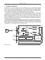
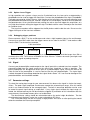
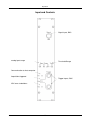
TR20-160
Lidar transient recorder
Manual
December 7, 2012
Licel GmbH, Gustav-Meyer-Allee 25, 13355 Berlin, Germany
CONTENTS
Contents
1 Product description
3
2 Principle of operation
4
3 Preparation for use
3.1 Installation of I/O card (only for systems with NI-DIO interface)
3.2 Software driver installation . . . . . . . . . . . . . . . . . . . . .
3.3 Transient recorder hardware address . . . . . . . . . . . . . . .
3.4 Memory Length . . . . . . . . . . . . . . . . . . . . . . . . . . .
3.5 Trigger . . . . . . . . . . . . . . . . . . . . . . . . . . . . . . . .
3.5.1 Option: Trigger-Splitter . . . . . . . . . . . . . . . . . . .
3.5.2 Option: Laser-Trigger . . . . . . . . . . . . . . . . . . .
3.5.3 Debugging trigger problems . . . . . . . . . . . . . . . .
3.6 Signal . . . . . . . . . . . . . . . . . . . . . . . . . . . . . . . .
3.7 Parameter settings . . . . . . . . . . . . . . . . . . . . . . . . .
.
.
.
.
.
.
.
.
.
.
5
5
5
5
6
7
7
8
8
8
8
4 Operation
4.1 Signal acquisition . . . . . . . . . . . . . . . . . . . . . . . . . . . . . . . . . . . . . . .
4.2 Bin shift . . . . . . . . . . . . . . . . . . . . . . . . . . . . . . . . . . . . . . . . . . . .
4.3 Analog background . . . . . . . . . . . . . . . . . . . . . . . . . . . . . . . . . . . . . .
9
9
11
11
5 Maintenance
5.1 Safety . . . . . . . . . . . . . . . . . . . . . . . . . . . . . . . . . . . . . . . . . . . . .
5.2 Cooling . . . . . . . . . . . . . . . . . . . . . . . . . . . . . . . . . . . . . . . . . . . .
5.3 Calibration . . . . . . . . . . . . . . . . . . . . . . . . . . . . . . . . . . . . . . . . . .
11
11
12
12
6 Trouble shooting
14
7 Specifications
15
2
.
.
.
.
.
.
.
.
.
.
.
.
.
.
.
.
.
.
.
.
.
.
.
.
.
.
.
.
.
.
.
.
.
.
.
.
.
.
.
.
.
.
.
.
.
.
.
.
.
.
.
.
.
.
.
.
.
.
.
.
.
.
.
.
.
.
.
.
.
.
.
.
.
.
.
.
.
.
.
.
.
.
.
.
.
.
.
.
.
.
.
.
.
.
.
.
.
.
.
.
.
.
.
.
.
.
.
.
.
.
.
.
.
.
.
.
.
.
.
.
Product description
1
Product description
The licel transient recorder is a data acquisition system for fast repetitive photomultiplier current signals, which are transformed at the internal 50 Ohm termination to a voltage between 0... -500 mV.
The signal is recorded simultaneously by a 12Bit, 20MHz analog to digital converter and a discriminator which detects voltage pulses above a selected threshold in the range 0... -100 mV. By using this
combination of analog and photon counting detection the licel transient recorder is especially suited
to record high dynamic range signals in lidar applications.
Each TR 20-160 contains 2 preamplifiers optimized for high linearity for analog detection and for
maximum speed and gain for photon counting, a 12-Bit A/D converter with fast memory for 16k of
single shot data, a discriminator with variable threshold, counter and multi channel scaler as well as
a hardware adder to perform summation of up to 4094 shots on board. Data transfer and selection
of input ranges and discriminator threshold is realized by a paralell data bus, connected to a PC
I/O-card or Ethernet controller. Up to 16 transient recorders can be controlled and readout using the
same bus.
3
Principle of operation
2
Principle of operation
An acquisition system using the TR20-160 can be configured for up to 16 simultaneous detection
channels. Such a system is configured by using a HF cassette mounted transient recorder module
for each channel, a rack comprising power supplies and interface ports and a PC or Apple computer
which is equipped with a Ethernet connection or a National Instruments digital I/O card (DIO-32HS).
Each channel can be configured and controlled separately by the host computer.
The basic setup used to amplify and record signals in the licel transient recorder is shown in the
schematic below: For analog detection the signal is amplified, according to the input range selected,
and signals below a frequency of 10MHz are passing the anti-alias filter to be digitized by a 12Bit
20MHz analog to digital converter. Each signal is written to a fast memory which is readout after
each shot and added to the summed signal in a RAM. Depending on the trigger input on Trigger A or
Trigger B, the signal is added to RAM A or B, which allows acquisitions of two repetitive channels if
these signals can be measured sequentially.
At the same time the signal part in the high frequency domain above 10 MHz is amplified and a
250 MHz fast discriminator detects single photon events above the selected threshold voltage. Two
different settings (threshold low and threshold high mode) of the preamplifier can be controlled by
software together with 64 different discriminator levels. Again the signal is written to a fast memory
and added to the summation RAM after each acquisition cycle.
'
$
@
@
@
@
@
@
@
@
@
@
Discriminator Level
Trigger
A
&%
'$
FIFO
'$
AntiHH
H
- Amp
- Alias- 12bit - 20MHz
AD Converter
filter
'$
&%
- Input
Range Selection
H
&% HH
H
250MHz
- Amp HH Counter
- Discriminator
'$ HH
H
?
-
ASIC
RAM Bank A RAM Bank B -
Trigger
B
Summation
-
&%
Interface 16 bit
&
%
Schematic setup
4
Preparation for use
3
3.1
Preparation for use
Installation of I/O card (only for systems with NI-DIO interface)
Your computer should be turned off and the power cable removed before you open the housing and
plug a NI DIO-32HS into a slot of your PC.
For further information on the NI card please refer to the National Instruments documentation.
3.2
Software driver installation
The software package supplied with your licel transient recorder contains LabVIEW modules and
alternatively C-sources to be integrated in your own acquisition programs and a few ready to use
LabVIEW acquisition modules to perform multichannel measurements.
The module ”track.vi” can be used to check your signal at different input ranges and discriminator
thresholds. The output is displayed on screen only.
The module ”live display.vi” can be used can be used to have an oscilloscope like display for a
single transient recorder.
The module ”acquis.vi” can be used to perform a set of consecutive measurements with a predefined number of shots where the summed signals are written to disk.
3.3
Transient recorder hardware address
Each transient recorder is identified by its hardware address, which can be set using the DIL-4 switch
on the board, which is located close to the 50-pin interface connector. In multichannel systems the
transient recorders are factory set to consecutive addresses, starting at 0 for the leftmost channel in
the rack.
The addresses range from 0 to 15. Each address should be unique in the system. In order to
change the transient recorder address later you need to unmount the transient recorder first. Once
the right side panel is open on the right side of the board a red switch should be visible. The switch
encodes binary the address
The ON position corresponds to a binary 1.
5
Preparation for use
before Oct. 2009
since Oct. 2009
All switches are off, the resulting address is 0. This is
the factory default for the left most transient recorder in
a Rack-6 or the topmost in a Rack-2.
The lowest switch is on (20 ), the resulting address is 1
The lowest switch is on (20 ), the switch corresponding to
four is also on (22 ), the resulting address is 5
Connect the rear connector of the transient housing to the Ethernet or to the I/O-card, using the
interface cable supplied and turn on the power of transient recorder and computer. The hardware
address of each channel can now be verified by watching the Host I/O indicator, when different
channel numbers are selected in the acquisition software and any command is sent.
3.4
Memory Length
Starting from October 2009 TR units will have 64k deep memory, which can be configured by the
user for shorter memory depths.
Memory Depth
512
1k
2k
4k
8k
16k
32k
64k
6
7
8
OFF
ON
OFF
ON
OFF
ON
OFF
ON
OFF
OFF
ON
ON
OFF
OFF
ON
ON
OFF
OFF
OFF
OFF
ON
ON
ON
ON
The address selection above shows a 16k memory configuration
Setting the switch 5 to the ON position will limit the memory length to 322 bins. Setting it
to OFF will activate the behavior shown above
6
Preparation for use
3.5
Trigger
Connect your trigger source to the Trigger A or Trigger B input. Make sure, that your trigger source
is able to drive the required 50 Ohm input load. Depending on your input the signal acquired will be
summed and stored to memory A or B. This can be used to acquire two alternating signals.
Any trigger pulse which occurs during the acquisition and summation will be ignored as well as
trigger pulses after more than 4094 acquisitions on either trigger A or B.
A valid trigger pulse is indicated by the ”Run” LED.
Typical trigger sources are:
• The laser Q-switch out pulse,
• the a photodiode picking up a fraction of the outgoing beam,
• a function generator
• a timing pulse generator.
Laser Q-switch out The signal coincides with the actual laser shot. Typical lasers migh have
difficulties to drive the required 50 Ω input impedance and produce a pulse that excceds 2.5V for
more than 150ns. In this case the pulse needs amplification. A driving circuit scheme can be found
at http://www.licel.com/PulseShaperTrigger.pdf.
Photodiode Licel supplies a solution for this as described under Option: Laser-Trigger which will
drive the transient recorder. A custom made solution should deliver 2.5V @ 50 Ω for more than
150ns.
Function generator This is very convenient source for lab testing, connect the sync out of the
function generator to the transient recorder input as described below.
Timing generator One should use this option if a pretrigger is required or a chopper wheel is used.
Licel supplies a small module that fullfills the typical LIDAR system requirements.
3.5.1
Option: Trigger-Splitter
In multichannel systems a trigger splitter is integrated into the power supply in the 6-channel rack.
You can select between two setups to trigger all transient recorders in a rack 6 simultaneously or
individual triggering of each transient recorder.
a) Common trigger using the trigger splitter: The trigger splitter is integrated into the power
supply in the 6-channel rack. Connect your electrical trigger source to the ”Trigger in” input. This
trigger source will trigger all transient recorders in the rack 6 together and acquire signals into memory
A. An additional connection to the BNC trigger inputs of each transient recorder is NOT required.
b) Individual trigger for each transient recorder: Connect your trigger source to the Trigger A or
Trigger B input of each transient recorder. Make sure, that your trigger source is able to drive the
required 50 Ohm input load. Depending on your input the signal acquired will be summed and stored
to memory A or B. This can be used to acquire two alternating signals or to store two consecutive
sets of up to 4094 acquisitions.
7
Preparation for use
3.5.2
Option: Laser-Trigger
In high repetition rate systems using a passive Q-switched laser, the laser pulse as detected by a
photodiode can be used to trigger the acquisition. Connect the photodiode to the input ”Photodiode”
(Cathode connected to shield), Direct a small fraction of the laser light (use any back-reflection) onto
the photodiode while observing the ”Monitor” output on an oscilloscope. Increase the threshold with
the potentiometer. At very low discriminator settings the noise signal will trigger the acquisition, at a
very high discriminator setting the trigger will stop. Find both extreme values and adjust the threshold
to a medium level.
The transient recorders will be triggered via the 50 pin bus cable inside the rack. Do not use the
Trigger A/B inputs of the transient recorders.
3.5.3
Debugging trigger problems
Please connect a BNC T to the oscilloscope and select a high impedant input at the oscilloscope.
Connect then one BNC cable from the trigger source to one side of the BNC T and another cable
from the BNC-T to the transient recorder.
1 MΩ termination
Trigger source
?
?
Oscilloscope
Transient recorder
Record then the shape of the trigger pulse at the oscilloscope, it should be longer than 150 ns
and more than 2.5V. The rise time should be less than 20 nsec. If it does not match you might need
to amplify the signal or prolong the pulse.
3.6
Signal
Connect your photomultiplier anode output to the signal input of the selected transient recorder. The
connecting cable from the signal source to the signal input should be as short as possible. The
builtin preamplifier are designed for direct input of a photomultiplier signal, where the internal 50
Ohm resistor of the preamplifier is used as load resistor for your photomultiplier. The signal input
is diode clamped for overvoltage detection but signal levels above -15 V can lead to damage of the
protection diodes and should be avoided.
3.7
Parameter settings
To select the analog input range for your measurement first observe the signal in single shot acquisitions. The peak signal amplitude should never exceed the selected input range, since this would
result in an underestimation of the averaged signal. The built in overrange detection can be used
to control the peak signal during an acquisition. If any single signal exceeds the input range selected, the affected memory bin will be marked as clipped. By evaluation of this information after the
measurement, the affected memory bins can be identified.
The discriminator setting should be selected based on the pulse height distribution. Too low
discriminator levels (below 3) make the system vulnerable to RF noise.
The Threshold Range can be set to high if large photons will cause an after pulsing that would
otherwise overflow the internal preamplifier.
8
Operation
4
Operation
4.1
Signal acquisition
Using the LabVIEW module ”aquis.vi” you can perform automatic data acquisitions using multiple
signal sources and transient recorders. Each acquisition cycle is performed by the following steps:
1. The discriminator is set to the selected discriminator threshold, the preamplifier is set to the
desired input range.
2. The internal summation memory and acquisition cycle counter is cleared. This step is indicated
by the ”Run” LED of each transient recorder.
3. The trigger is armed. Start of your measurement.
4. Deactivation of the trigger input, end of acquisition. This step can be done by the user or is
performed automatically after 4094 acquisitions.
5. Readout of the summed data for analog and photon counting signals from memory 1 and/or 2.
Readout of the counted number of shots.
During the measurement valid trigger pulses are displayed by the LED ”Run” of each module. A
signal above the selected analog input range, leading to clipping of the signal is indicated by the LED
”Clip”. Each communication between transient recorder and host computer is indicated by the LED ”
I/O”.
9
Operation
Input and Controls
9
analog input range
HH
j
H
)
Signal Input, BNC
Threshold Range
Communication to host computer
PP
P
q
P
Acquisition triggered
ADC over-/underflows
@
I
@
@
PP
Pq
P
@
PP
Pq
P
10
Trigger Inputs, BNC
Maintenance
4.2
Bin shift
The analog and the photon counting data has a fixed shift between them. This is a result of two
factors:
• Analog Bandwidth, the preamplifier contains an antialias filter which has a bandpass of half the
sampling frequency this delays the analog signal with respect to the photon counting by 2 bins
• ADC pipelining, modern ADCs sample the voltage in a multiple step process so that the sample
result will be available several clock cycles later after the actual sampling took place.
You can verify the bin shift for your TR by measuring under dark conditions the dark counts
from a PMT with applied HV. When you take single shot measurements with Track.vi and switch
between the analog and photon counting data set you will see that the needles in photon counting
also correspond to needles in the analog but they are at slightly different positions. This shift is fixed
and does not change with time for a given TR.
4.3
Analog background
The analog background is elevated intentionally, there are several reasons
a) We use a unipolar input range of the ADC instead of a bipolar, where the signal could go from
-500mV to +500mV. The reason to use the unipolar is to give you the best possible ADC resolution,
as positive signals will not come out from a PMT, it is negative going usually. There are PMT’s out
that make this different but they are seldom and use typically a preamp inside the housing which will
not fit to the TR without a modification of the preamp.
b) The signal however can not start from 0 directly because every single photon while going
negative typically also shows a slight overshot into the positive direction. You can observe this using
the Track.vi. Connect a dark PMT with HV to the transient recorder and look for the photon counting
data, once you see a single count switch the display to the analog mode. You will see a spike and the
little undershoot below the baseline. The signal is displayed inverted so negative going photons will
be go in the positive direction.
c) As those overshoots are part of the signal they need to take part in the average computation.
A too low offset will clip them and then your average is compromised. To make sure that this will not
happen we do two things:
• we elevate the analog background level
• we provide the clipping information both on the front panel and in the data that is retrieved from
the transient recorder.
d) The clipping lamp goes bright when the ADC sees a 0 or a full scale 0xFFF =4095 value. At both
conditions we are not sure that the average is not compromised by clipping. As soon as the lamp goes
on we will also mark internally the bin as clipped. (See http://www.licel.com/programmingManual.pdf
page 19 Memory organization.)
This clipping information is used in the Track.vi and Live display.vi when you switch the Set Overflow Values to 0 and it will when overflows occur mark ”innocent” looking averages with down to zero
going needles. It is not used in the Acquis.vi as it would reduce signal quality and make a lot of
algorithms grinding to a halt.
5
5.1
Maintenance
Safety
Before opening the rack the power supply should be turned off and the power cable removed for your
personal safety. When opening the power supply cassette be aware of capacitors that can be still
charged and lead to high currents although the unit is not connected to AC power.
11
Maintenance
Each transient recorder can be removed after opening the 4 screws at the front panel.
To remove the power supply unit, 2 additional screws below the side cover of the 19” rack have to
be removed.
5.2
Cooling
The power supply of the transient recorders is using linear voltage controllers and therefore should be
air cooled during operation. The air inlet is located at the lower front side of the housing the outlet is at
the top rear side. Make sure that the ventilation system is not obstructed. Three LED’s are indicating
the supply voltage of 5 and +15V. If any of these LED’s is off, check the power supply fuses. They
are located at the rear side of the housing. Additional fuses are located on the power supply boards
inside the cassette. AC fuses are located in the power cable terminal at the rear side of the housing.
5.3
Calibration
If the clip lamp at the transient recorder flashes during acquisitions you might need to check for the
over/-underflow. This is done with the Track or Live Display.vi where the ”Set Overflow to 0” switch
is activated. If you see then needles that go down to 0 for small signals, then the offset for the input
might be to low and changing the calibration would help to solve this. If you are in doubt send a
screen shot of the Track.vi with the signal to Licel to discuss if a recalibration is required.
The offset and gain of each channel can be recalibrated by using the following procedure:
1. Turn on the system for at least 20 minutes to reach stable temperature conditions.
2. Unscrew the 4 screws at the front plate of the transient recorder to be calibrated and pull out
the cassette about 15 cm.
3. Use a plastic shielded screwdriver to turn the trimmers which can now be accessed from the
right hand side. Connect a trigger source and start with the offset in the 500 mV range. Without
input signal the offset should be 5 mV.
4. Apply a -480 mV DC signal and set the gain until this voltage readout correct.
5. Calibrate again alternating the offset and gain until both settings are correct. The repetitive
procedure is necessary since the gain setting affects also the offset level.
6. Calibrate the 100 mV and 20 mV range using the same procedure as above.
An offset level above your single shot noise amplitude is necessary to prevent clipping by underflows of the A/D converter. Like overrange signals this would lead to wrong results in the summed
signal of an acquisition.
12
Maintenance
BNC Input
100mV gain
100mV offset
500mV offset
20mV offset
20mV gain
The arrows show the direction to increase the offset or gain
13
500mV gain
Trouble shooting
6
Trouble shooting
Failure of a power supply: Three LED’s in the front of the power supply unit show the operation for
+5V, -5V and +15V supply. In case of failure of one supply check the fuses in the back of the power
supply. Check the fuses inside the power supply cassette.
No data transfer: The LabVIEW error message ”Error -10800 occurred at ...” means that no handshake signal from the transient recorder was received with the hardware address selected. Check
the hardware address selected in your configuration first. Check the interface cable for correct connection. The host I/O LED of each transient recorder indicates a handshake signal between I/O card
and transient recorder.
Analog and photon counting signal is 0 Check whether memory 1 is readout when you use
Trigger input A, or memory 2 is readout when you use trigger input B. Do the ”Run” LED and the
number of shots readout indicate valid trigger pulses? Check the slope of your trigger source (trigger
on rising edge).
14
Specifications
7
Specifications
Analog acquisition:
Signal input range:
A/D Resolution:
Sampling rate:
Lidar spatial resolution:
Bandwidth:
A/D differential nonlinearity:
A/D integral nonlinearity:
Spurious free dynamic range:
S/N single shot:
Memory depth:
Typical binshift:
Summation memory:
Protection:
Input impedance:
Coupling:
0... -20 mV, 0... -100 mV, 0... -500 mV
12Bit
20 MSamples/second.
7.5 m.
DC-10 MHz.
typ. 0.65 LSB, max. 1.25 LSB @25o C.
typ. 1 LSB @25o C.
74 dB
66 dB @ 100 mV input range (50 µV).
322 bins.
7 bins
2 channels 24 Bit, 4094 acquisitions.
Diode clamped.
50 Ω
DC
Photon Counting Acquisition:
Max. count rate:
Signal input range:
Input impedance:
Protection:
Discriminator:
Lidar spatial resolution:
Memory depth:
Summation memory:
Input impedance:
Bandwidth:
250 MHz.
0... -25 mV/0..-100 mV (thresh low/high)
50 Ω
Diode clamped.
64 levels for each input range, software controlled.
7.5 m.
322 bins.
2 channels 16 Bit, 4094 acquisitions.
50 Ω
0 - 300 MHz
no dead time or overlap between bins
Trigger:
Impedance:
Threshold:
Slope:
Trigger delay and jitter:
Repetition Rate:
Power Consumption:
+5.1V
-5V
2 Trigger inputs to acquire signals in 2 separate summation
memories.
50 Ω
2.5 V
positive
50 ± 25 ns.
300 Hz
0.6A
0.5A
15