Transcript
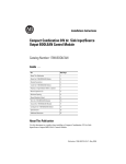
Specifications
ATTENTION
Disconect power to device before installing or servicing.
Do not touch the terminals of controller when voltage is applied.
Do not allow metal fragments or lead wire scraps to fall inside this product. This may cause electric
shock, fire or malfunction.
Do not use this product where subject to flammable or explosive gas.
This product is UL listed as open type Process Control Equipment and must be mounted in an
enclosure.
More than one disconnect switch may be required to de-energize the equipment before servicing.
Signal inputs are SELV, limited energy.
Caution - To reduce risk of fire or Electrical shock, Do not interconnect the outputs of different Class 2
circuits.
Never disassemble, repair or modify the product.
The life expectancy of the output relays varies greatly with the switching capacity and other switching
conditions. Always use the output relays within their rated load and electrical life expectancy. If an
output relay is used beyond its life expectancy, its contacts may become fused or burned.
Use copper wire only 24-14 AWG stranded or solid. Torque screws to 0.74 to 0.90 Nm or 6.5 to 8 lb-in.
Only two wires of same type and size per terminal.
To maintain safety in the event of malfunction of the temperature controller, we recommend taking
safety measures, for example, installing an excessive temperature rise prevention alarm on a separate
line. If malfunction prevents control, they may result in an accident.
To reduce the risk of electrical shock or fire, install in a Pollution Degree 2 environment (controlled
environment relatively free of contaminants).
Set the configuration parameters of the controller and test them to ensure they are suitable for the
application being controlled. If not properly configured unexpected operations may occur resulting in
property damage or accidents.
Temperature/ Process Controller
Model 900-TC16
(Series B)
English
10000022595 (Version 00)
Printed In China
If the semiconductor (Triac) output is used and an excessive electrical surge or noise spike is
impressed on the output terminals, a short circuit failure of the triac output is likely to occur. This could
result in excessive current draw and possible fire. Use surge suppression to prevent excessive surges
and fusing to help prevent an over current condition.
For detailed operating instructions, please refer to the 900-TC16 User's Manual
(900-UM007_-EN-E).
It can be found online at http://www.ab.com/manuals/.
ATTENTION
When the product is used under the circumstances or environment below, ensure adherence to
limitations of the ratings and functions. Also, take countermeasures for safety precautions such as
fail-safe installations.
injury,
ON before you turn the controller ON.
(11) A switch or circuit breaker should be provided close to this unit.
The switch or circuit breaker should be within easy reach of the operator, and must be marked
as a disconnecting means for this unit.
(12) If you remove the controller from its case, or put the controller into its case, never touch nor
apply shock to the terminals and the electronic parts inside.
Make sure the electronic components and the case are not contacted when inserting the internal
mechanism. Always ensure power is OFF when doing any maintenance on the controller or
associated circuits.
(13) Cleaning: Do not use paint thinner or the equivalent. Use standard grade alcohol to clean the
outside of the product.
(14) Consider the 2 second delay required for the controller relay outputs to respond when you
design your control system.
(15) If an option unit is used in the system refer to its Installation Manual before operating.
(16) Make sure that the Digital Controller has 30 minutes or more to warm up after turning ON the power
(17) The output may turn OFF when shifting to certain levels. Take this into consideration when
performing control.
(18) The number of EEPROM write operations is limited. Therefore, use RAM write mode when frequently
overwriting data during communications or other operations.
Memory protection---EPROM (non-volatile memory) (Number of write operations:1,000,000)
* Use for applications where death or serious property damage is possible and extensive safety
precautions are required.
Dimensions
Mounting
In the pack:
• Main unit
• Watertight packing
• Adapter
• Instruction manual
• Terminal cover
Dimensions (mm)
6
91.0
1.5
Connections (The applicability of the electric terminals varies with the type of 900-TC16.)
Individual mounting (mm)
Side-by-side mounting (waterproof not possible) (mm)
(48 x number of units -2.5)
+1
0
Adapter
12
7
3
13
8
4
14
9
5
15
10
Solderless terminal size: M3.5
Terminal
cover
* The main unit can be removed for maintenance without disconnecting the terminal wiring.
* Do not remove the terminal block. Doing so may result in failure or malfunction.
45 0
2
+.06
45 0
V
When waterproofing is required, be sure to mount
the controller separately.
Attach the waterproof packing from the terminal
side and then insert the controller to the panel.
Recommended panel thickness is 1 to 5 mm.
• Insert the controller through the hole in the panel. Push the adapter on from the rear and
fasten temporarily, removing any gap between the controller, panel and adapter. Finally,
secure two mounting screws alternately keeping the torque to between 0.29 to 0.39 N•m.
• Make sure that the surrounding temperature does not exceed the allowable operating
temperature given in the specifications especially when two or more controllers are mounted.
Names of parts on front panel
• No.1 display
Process value or set data symbol
• Press the key and the
key
together for at least 3 seconds to switch
to protect group .
• No.2 display
Set point, set data read-out value or changed
input value
• Mode key
Press this key to change the contents of
the display.
Press this button for 1 s or longer for
reverse scroll.
• Up and Down keys
Use the keys to change the values displayed on
the No.2 display.
Each press of
key increments or advances the
values displayed on the No.2 display.
Each press of key decrements or returns the
values displayed on the No.2 display.
• SUB1: Auxiliary output 1 indicator
Lit when the function assigned to auxiliary
output 1 is ON.
• SUB2: Auxiliary output 2 indicator
Lit when the function assigned to auxiliary
output 2 is ON.
• SUB3: Auxiliary output 3 indicator
Lit when the function assigned to auxiliary
output 3 is ON.
• HA: Heater burnout alarm/Heater short
alarm/Heater overcurrent alarm indicator
Lit when a heater burnout alarm, heater
short alarm, or heater overcurrent alarm
has occurred.
Operation menu
Input type
Thermocouple
Temperature input type
●Initial setting group Operation stopped.(control/alarm are both stopped.)
Setting
0
1
2
3
JPt100
4
5
K
6
7
J
8
9
T
10
11
E
12
L
13
U
14
15
N
16
R
17
S
18
B
19
10 - 70°C
20
60 - 120°C
21
115 - 165°C
22
140 - 260°C
23
0 - 50mV
Input
Platinum
resistance
thermometer
Infrared
Thermosensor
Analog input
Thermocouple
Pt100
24
25
W
PLII
Setting range
/ -300 to 1500 (°F)
–200 to 850 (°C)
–199.9 to 500.0 (°C) / -199.9 to 900.0 (°F)
/ 0.0 to 210.0 (°F)
0.0 to 100.0 (°C)
–199.9 to 500.0 (°C) / -199.9 to 900.0 (°F)
/ 0.0 to 210.0 (°F)
0.0 to 100.0 (°C)
/ -300 to 2300 (°F)
–200 to 1300 (°C)
–20.0 to 500.0 (°C) / 0.0 to 900.0 (°F)
/ -100 to 1500 (°F)
–100 to 850 (°C)
–20.0 to 400.0 (°C) / 0.0 to 750.0 (°F)
/ -300 to 700 (°F)
–200 to 400 (°C)
–199.9 to 400.0 (°C) / -199.9 to 700.0 (°F)
/ -300 to 1100 (°F)
-200 to 600 (°C)
/ -100 to 1500 (°F)
–100 to 850 (°C)
/ -300 to 700 (°F)
–200 to 400 (°C)
–199.9 to 400.0 (°C) / -199.9 to 700.0 (°F)
/ -300 to 2300 (°F)
–200 to 1300 (°C)
/ 0 to 3000 (°F)
0 to 1700 (°C)
/ 0 to 3000 (°F)
0 to 1700 (°C)
/ 300 to 3200 (°F)
100 to 1800 (°C)
/ 0 to 190 (°F)
0 to 90 (°C)
/ 0 to 240 (°F)
0 to 120 (°C)
/ 0 to 320 (°F)
0 to 165 (°C)
/ 0 to 500 (°F)
0 to 260 (°C)
Use the following ranges for scaling: –1999 to 9999,
–199.9 to 999.9, Vary Depending on "L", "H" value
/ 0 to 3200 (°F)
0 to 2300 (°C)
/ 0 to 2300 (°F)
0 to 1300 (°C)
Analog
input type
Input type
Voltage input
*6
*6
Scaling Lower Limit
(only when setting analog input)
*1
0
No alarm function
1
Deviation upper/lower limit
ON
OFF
2
Deviation upper limit
ON
OFF
3
*1
*1
Alarm output function
Positive alarm value (X) Negative alarm value (X)
*6
Decimal Point
(only when setting analog input)
Temperature Unit
*6
4
5
6
7
8
X
ON
OFF
Deviation lower limit
Deviation upper/lower range
Deviation upper/lower limit
standby sequence ON
SP
*6
ON
OFF
Deviation lower limit
standby sequence ON
ON
OFF
Absolute value upper limit
ON
OFF
Absolute value lower limit
ON
OFF
10
Absolute value upper limit
standby sequence ON
ON
OFF
Absolute value lower limit
standby sequence ON
ON
OFF
SP
LBA (only for alarm 1)
13
PV Change Rate Alarm
°F=
(C stands for Celsius, F for Fahrenheit)
(No. 1 display flushes
then the control stops)
Hold down
for at least
1 second
SP
X
SP
X
0
X
0
X
0
X
0
TC/PT
Analog input multi-input
Standard or Heating/Cooling
Standard control =
Heating and cooling control =
(Select standard control or heating
and cooling control as required)
ST (Self-Tuning)
ST ON =
ST OFF =
X
*6
*6
*4
*6
(S. Err)
(E333)
(E111)
Input error
*2
Action
A/D converter error
*2
After the correction of A/D converter error, turn the
power OFF then back ON again. If the display remains
the same, the controller must be repaired. If the display
is restored to normal, then a probable cause can be
external noise affecting the control system. Check for
external noise.
Memory error
Turn the power OFF then back ON again. If the display
remains the same, the controller must be repaired. If the
display is restored to normal, then a probable cause can
be external noise affecting the control system. Check for
external noise.
Control
output
Alarm
OFF
Operates
as above the
upper limit.
Alarm 2 Type: Specified models only
*3
*4
Transfer Output Type
*6
Transfer Output Upper Limit
*6
If the input value exceeds the display limit (–1999 to 9999), though it is within the control range, [[[[ will
be displayed under –1999 and
above 9999. Under these conditions, control output and alarm
output will operate normally.
Refer to "900-TC User's Manual" for details of control range.
*2: Error shown only for"Process value / Set point". Not shown for other status.
15
900TC16P1V2
*6
Manual Reset Value
(Unit: %)
100%AT Execute
*6
Hysteresis
(Heating)
Temperature Input Shift
(Unit:°C or °F)
*6
Hysteresis
(Cooling)
Upper Limit Temperature
Input Shift Value
when 2 point input shift
is selected
Lower Limit Temperature
Input Shift Value
when 2 point input shift
is selected
*6
Soak Time
*6
Wait Band
*6
Integral Time
(Unit: secs)
*6
MV Upper Limit
*6
Derivative Time
(Unit: secs)
*6
MV Lower Limit
*6
Cooling Coefficient
*6
MV Change Rate Limit
*6
Dead Band
*6
Extraction of Square
Root Low-cut Point
Alarm value 1 *4
*6
Alarm value upper limit 1
*4
*6
Alarm value lower limit 1
*4
*6
Alarm value 2 *4
*6
Alarm value upper limit 2
*4
* 6: The grayed-out parameters may not be displayed according to the model and
parameter.
Alarm value lower limit 2
*4
Protection function is to prevent unwanted settings. It restricts the parameter to be used
-----------------------------------------------------------------------------------------------------------------------------------------------------------------------or designates if operation of the key is valid or invalid.
------------------------------------------------------------------------------------------------------
Hold and
keys
down for at least
3 seconds
Protect group
Adjustment group is for entering set
values and shift values for control.
●Protection function
Operation / Adjustment protection
The following table shows the relationship between settings and protect limits related to
Operation group and Adjustment group.
: Can be displayed and changed
Set value
Group
: Can be displayed
1 2 3
0
: Can not be displayed and change
Process value ○
to other groups not possible
◎
Operation group Set point
◎
Others
Default setting : 0 (shaded)
◎
Adjustment group
Initial setting/Communications protection
Operation / adjustment
protect
Initial / Communication
protect
Parameter change protect
Move to protect group
*6
Linear Current Output
Extraction of Square Root Enable
(Only when analog input is set)
OFF
OFF
14
15
SP Ramp Set Value
Transfer Output Lower Limit
Initial setting group enables users to specify their
preferred operating conditions (input type, alarm type,
control method, etc.)
OFF
13
CT1
CT1
*6
Alarm 2 Hysteresis
*6
*6
OFF
14
Proportional Band
*6
This protect level restricts movement to the initial setting group,
communications setting group and advanced function setting group.
Set value
Check the wiring of inputs, disconnections, shorts
and input type.
DO
NOT
USE
*6
Status at error
Meaning
DO NOT
15
USE
-
When control stop =
0
When an error has occurred, the No.1 display shows the error code. Take
necessary action according to the error code, referring the table below.
15
13
CT2
+
11 Control output 2
Control output 2 ・Voltage output:
12 12 VDC, 21 mA
Run/Stop
When control start =
Error display (trouble shooting)
No.1 display
*6
Press
(less than
1 second)
X
*1: Upper and lower limits can be set for parameters 1, 4 and 5 to provide for
different types of alarm. These are indicated by the letter "L" and "H".
• Default = "2" (shaded)
14
DO NOT
USE
14
12
*6
0
ON
OFF
11
Soak time remain
Hold and
keys
down for at least 1 second
Alarm 1 Hysteresis
X
0
DO NOT
USE
13
A
Only the value set to the
: Temperature Input Shift parameter is
applied to the entire temperature input range. When the process
value is 200°C, the process value is treated as 201.2°C after input
shift if the input shift value is set to 1.2°C.
The process value is treated as 198.8°C after input shift if the input
shift value is set to -1.2°C.
AT Execute / Cancel
Operation group should normally
be used during operations.
Alarm 1 Type: Specified models only *3
0
ON
OFF
13
CT1
B
RS-485
12
• °C / °F : temperature unit
The temperature unit is displayed
when the configured display value is
a temperature.
When this parameter is set to "°C",
“C ” is displayed, and when set to
“ °F”, “F ” is displayed.
This flashes while ST(Self-Tuning) is
activated.
•
: Protection indicator
Lit when Setting Change Protect is
ON (disables the Up and Down Keys).
• MANU: Manual output indicator
Lit when the Auto/Manual Mode is set
to Manual Mode.
Adjustment group
X
ON
OFF
15
11
A
•100-240V AC Type
900900900900900900•24V AC/DC Type
TC16NEIM TC16NACEIM TC16NCOMV2 TC16NCOM TC16NACCOM TC16NCOMP3
(no polarity)
• OUT2: Control output 2 indicator
Lit when control output 2 is ON and not lit
when it's OFF.
• STOP: control stop indicator
Lights when event input or “Run/Stop” is
stopped during operation.
During control stop, functions other than
control output are valid.
• CMW: communications writing enable/
disable indicator
Lights when communications writing is
“enabled” and is out when it is “disabled”.
In Direct operation (Cooling) =
X
-
DO
NOT
USE
14
Control output2
• OUT1: Control output 1 indicator
Lit when control output 1 is ON and not lit
when it's OFF. For a current output, lit for
greater than a 0% output.
SP
ON
OFF
DO NOT
15
USE
13
B
RS-485
12
*6
In Reverse operation (Heating) =
SP
15
11
· Since the voltage output (control output 1) is not electrically insulated from the internal wiring, one or other of the control output
terminals must be left unearthed when using an earthed (grounding) type thermocouple. (Connection makes measurements unreliable
due to ground loop currents.) Basic insulation is provided between the voltage outputs (control output 2) and internal circuits.
· Basic insulation is provided between power supply, input, output and communications (for applicable models). If double insulation is
required provide supplemental insulation as defined by IEC60664.
・This is a class A product.
In residential environment areas it may cause radio interference, in which case the user may be required to take adequate measures to
reduce interference.
Set point during
SP ramp
*6
Direct/Reverse Operation
X
ON
OFF
14
+
A
Program start
*6
Control Period (Cooling)
(Unit: Seconds)
Vary with "L", "H" values
ON
OFF
15 10
DO
NOT
USE
B
RS-485
12
*6
PID/ONOFF
In ON/OFF control =
In 2-PID control = pid
*6
SP
X
*6
*6
SP
Vary with "L", "H" values
5
POWER ON
SP Lower Limit
*6
*6
12
Hold down
for at least
3 seconds
°C=
Control Period (Heating)
(Unit: Seconds)
X
ON
OFF
B
+
11
40%AT Execute
X
SP
L H
ON
OFF
Deviation upper limit
standby sequence ON
ON
OFF
Input power supply
A
13
DO NOT
USE
14
CT1
9
B
12
Program Pattern
Vary with "L", "H" values
L H
ON
OFF
9
11
X
14
EV1
EV2
13
8
*6
SP
SP
4
EV2
12
Adjustment group
SP Upper Limit
Output off
L H
13
PV/SP
Alarms
Alarm type
3
11
RS-485
EV1
Operation group
Scaling Upper Limit
(only when setting analog input)
• The default is “0” (shaded).
Setting
11
Auxiliary
output 2
2 12 7
Auxiliary
output 1
The setting data for the 900-TC-8 is shown here as an
example.
*5
Setting range
Setting
0
Use the following ranges for scaling: –1999
1
to 9999, –199.9 to 999.9, –19.99 to 99.99,
2
–1.999 to 9.999
3
4
Input
4 - 20mA
0 - 20mA
1 - 5V
0 - 5V
0 - 10V
Auxiliary output
Input Type *3
• The default is “5” (shaded).
•
will be display when a platinum resistance thermometer is mistakenly connected while input
type is not set for it. To clear the
display, correct the wiring and cycle the power supply.
Current input
+
11 6
1
Operation indicators
• Group key
Use this key to change groups:
Input type
+
-
+.06
6
45 0
11
60 min.
44.8
48.8
58
Watertight
packing
1
Control output 1
• Relay output
250 VAC 3A
Control output 1
(resistive load)
• Voltage output
12 VDC 21mA
A
• Current output +
DC4-20mA
mA
DC0-20mA
B
-
+.06
48 x 48
100-240VAC type
24V AC/DC type
50-60Hz
85 to 110% of the rated voltage
Approx. 7.5VA (AC100-240V)
Approx. 5VA (AC24V)
Approx. 3W (DC24V)
Indication accuracy
Thermocouple:
(Ambient temperature: 23°C) (±0.3 % of indication value or ±1°C,
whichever is greater) ±1 digit max.
Platinum resistance thermometer:
(±0.2 % of indication value or ±0.8°C,
whichever is greater) ±1 digit max.
Analog input:
±0.2 % FS ±1 digit max.
Event input
Output current: approx. 7 mA per contact.
ON:1 k ohm max., OFF: 100 k ohm min.
Contact input
ON: residual voltage 1.5 V max.,
No-contact input
OFF: leakage current 0.1 mA max.
Control output 1
Relay output: SPST-NO,
250 VAC, 3A(resistive load)
Voltage output: 12 VDC, 21 mA
Current output: 4 to 20 mA DC and
0 to 20 mA DC, load: 600 ohms max.
Electrical life of relay:
100,000 operations
Triac model: 1 million operations
Voltage output: 12 VDC, 21 mA
Control output 2
1ON/OFF or 2-PID control
Control method
SPST-NO, 250 VAC,
Auxiliary output
3 A(resistive load), electrical life:
100,000 operations
–10 to 55 C
Ambient temperature
(Avoid freezing or condensation)
RH 25 to 85%
Ambient humidity
–25 to 65 C
Storage temperature
(Avoid freezing or condensation)
Max. 2,000m
Altitude
T2A, 250V AC, time-lag,
Recommended fuse
low-breaking capacity
Front panel: Type 4X (UL50)
Degree of protection
IP66 (IEC 61010-1)
Rear case: IP20. Terminal section: IP00
*The temperature controller is mounted
on the flat surface of an enclosure that is rated
and marked “Type 4X for Indoor Use Only”
Weight
Approx. 150g (main unit only)
Setup category II, pollution
Installation environment
degree 2 (as per IEC61010-1)
Operating frequency
Operating voltage range
Power consumption
(1) Do not use this product in the following:
• Places directly subject to heat radiated from heating equipment.
• Places subject to splashing liquid or oil atmosphere (Excceds NEMA 4X).
• Places subject to direct sunlight, could discolor or cause excessive heat.
• Places subject to dust or corrosive gas (in particular, sulfide gas and ammonia gas).
• Places where intense temperature changes exceed the published ratings.
• Places subject to icing and condensation.
• Places subject to vibration and large shocks.
(2) Use/store within the rated temperature and humidity ranges.
Provide forced-cooling if required.
(3) To allow heat to escape, do not block the area around the product.
Do not block the ventilation holes on the product.
(4) Be sure to wire properly with correct polarity of terminals.
(5) Use specified size (M3.5, width 7.2 mm or less) crimped terminals for wiring.
(6) Do not wire the terminals which are not used.
(7) Allow as much space as possible between the controller and devices that generate a powerful highfrequency or surge.
Separate the high-voltage or large-current power lines from other lines, and avoid parallel or common
wiring with the power lines when you are wiring to the terminals.
(8) Use this product within the rated load and power supply.
(9) Make sure that the rated voltage is attained within two seconds of turning the power ON.
(10) When executing self-tuning, turn the load and the controller ON simultaneously, or turn the load
* Use under circumstances or environment which are not described in the instruction manual.
RC1 9458732-2A
Installation
Power supply voltage
before starting actual control operations to ensure the correct temperature display.
Significance of CAUTIONS
Indicates information that, if not heeded, could result in
damage to the product, or faulty operation.
NOTICE
*3: Refer to the adjoining tables for details of input types and alarm types.
*4: Applicable only to models with alarm functions.
*5: Operation is stopped when moved to the initial setting group.
Restricts which parameters can be
displayed or changed, and restricts
change by key operation.
AT (auto-tuning)
* AT
in Adjustment level
Designate "
: 100% AT execute" or "
: 40%
AT execute" to execute AT and "off: AT cancel" to
cancel AT.
“ ” flashes
“100%AT Execute”
(control/alarm are both stopped.)
Other functions
In addition to the aforementioned, there are alarm hysteresis, automatic return of
display mode and others in the advanced setting group.
Refer to "900-TC16 User's Manual" for details.
For communications details, please refer to "900-TC communications User's
Manual".
“AT cancel”
Also when AT execution ends, the display
automatically returns to “
”.
Initial setting
group
Communications
setting group
Advanced function
setting group
0
1
2
Parameter change protection
Parameter changes by key operation are restricted.
OFF “
”: Parameter can be changed by key operation
ON “ ” : Parameter cannot be changed by key operation (“
(Protect group parameters can all be changed.)
: Change to
other groups
possible
: Change to
other groups
not possible
Default setting : 1
(shaded)
” will light.)