1
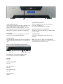
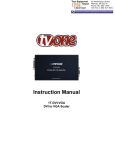
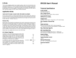
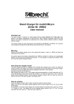
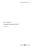
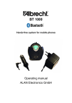
User manual
Hardware manual
Casablanca S series
S-2000 / S-4000 / S-4100
The following products carry the CE seal of conformity on the basis of the guidelines 89/336/EWG of the Commission of the European Community from
29. April 1991 for the alignment of legal regulations in the signatory states concerning communications devices, including mutual recognition of their
conformity. The following products are confirm to the low voltage directive 2006/95/EC.
These digital video editing systems are meant for use with hard-drives carrying the CE seal of conformity.
This product fullfills the requirements for CE labeling:
• EN 55022 (1994) + A1 (1995) + A2 (1997) Klasse A
• EN 55024 (1998) + A1 (2001) + A2 (2003)
• EN 55013 (2001)
• EN 55020 (2002)
• EN 61000-3-2 (2000)
• EN 61000-3-3 (1995) + A1 (2001)
FCC Class B Statement
This device complies with Part 15 of the FCC Rules. Operation is subject to
the following two conditions:
• This device may not cause harmful interference.
• This device must accept any interference received, including
interference that may cause undesired operation.
Warning: This equipment has been tested and found to comply with the limits
for a Class B digital device, pursuant to Part 15 of the FCC Rules. These limits
are designed to provide reasonable protection. This equipment generates, uses
and can radiate radio frequency energy and, if not installed and used in
accordance with the instructions, may cause interference to radio
communications. However, there is no guarantee that interference will not
occur in a particular installation. If this equipment does cause harmful
interference to radio or television reception, which can be determined by
turning the equipment off and on, the user is encouraged to try to correct the
interference by one or more of the following measures:
• Reorient or relocate the receiving antenna.
• Increase the separation between the equipment and receiver.
• Connect the equipment into an outlet on a circuit different from that to
which the receiver is connected.
• Consult the dealer or an experienced radio/TV technician for help.
Notice: Shielded interface cable must be used in order to comply with
emission limits.
Notice: Changes or modification not expressly approved by the party
responsible for compliance could void the user’s authority to operate the
equipment.
Remarks on Safety
These devices conform to the relevant safety regulations for computer equipment, including electrical office machines. In case you are in doubt as to
permission regarding setup in the intended surroundings, please contact your dealer or our service department.
• Transport the device only in the original packing or in other appropriate packing that guarantees protection against sudden movements or impacts.
• Condensation may result if the device is set up for operation after having been in colder surroundings. You should wait about 2 hours to let the device become dry and attain the temperature of the operating location.
• Read the notes below „Location Environment“ when setting up and before operating the device.
• Check that the operating voltage indicated on the type label is the same as the power outlet.
• The equipment is intended for connection to TN power system and IT power system for Norway only (phase to phase 230V).
• The equipment is a class 1 equipment and must be connected to an earthed outlet.
• This device is equipped with a safety-approved power cable and may only be connected to a grounded shockproof socket.
• The ON/OFF switch does not electrically separate the device from power. For complete separation from power the power cable must be pulled from the power outlet socket.
• Make sure that the power connector on the machine and the room shockproof socket are easily accessible.
• Place the power cables so that they are not a danger (tripping) and will not be damaged.
• Data lines must not remain connected during electrical storms.
• In emergencies (e.g. damaged casing, operating elements, or power line, liquid poured on the device, or foreign substances) you must turn off the device immediately, pull the power plug, and contact your dealer or our service department.
• Only qualified and authorized personnel may repair the device or install extensions. Unauthorized opening and improper repairs can mean real
danger for the user. In such cases the guarantee is no longer valid.
• The equipment was evaluated for use in a maximum ambient temperature of 35°C.
• System extensionsmust be conform to the requirements and rules for safety, electromagnetic interference, and telecommunications end devices. Installing other extensions may violate these requirements and rules, or damage the system. Your dealer or our service department can tell you which
system extensions are allowed.
• The unit contains a Lithium battery. It may only be removed or exchanged by authorized personnel. Incorrectly replacing the battery may lead to the battery exploding. Replace the battery only with the same or equivalent type recommended by the manufacturer. Dispose of used battery according to the manufacture‘s instructions.
Location Environment
• Make sure that the machine is operated at a location temperature of 10 to 35° centigrade.
• The location must be dry. Air humidity must not be more than 80% and must not be condensing.
•Make sure that there is sufficient circulation of the air in order to prevent thermal buildup. Do not cover up the machine. If you mount the
machine in a rack make sure that any warm air can directly be released. Generally, the room temperature (e.g. in the rack) should not exceed 30°
Celsius.
• Do not set up the machine on carpeting, blankets, or the like. Do not set up the machine near curtains, etc., because this entails the danger of
blocking the ventilation ducts on the machine.
• Do not set up the machine near heating or the like, and not in locations that are overly dusty, affected by direct sunlight, mechanical vibrations, or
where the machine can be knocked.
• The machine should be in a horizontal position when being operated. Do not set up the machine on an incline.
• Keep the machine at a distance from devices that emit a strong magnetic field (microwave ovens, large loudspeakers).
Proper waste disposal of this product (regulation of electronic device disposal):
(Applies to countries of the European Union and other countries with similar waste collection systems)
Please dispose of this device separately from other waste in order to prevent damage to the environment or human health by
uncontrolled waste disposal. Recycle the device to allow for lasting recycling of recourses.
Private users should contact the dealer they purchased the product from or contact the responsible public authorities to find
out how to dispose the product in an environment-friendly way. Industrial or commercial users should contact their suppliers
and check the terms and conditions of the purchase contract. This product may not be disposed together with other
commercial waste.
Casablanca S-2000 / S-4000 / S-4000 Pro / 4100
© Copyright 2008
All product names mentioned are registered trademarks of the corresponding firms. This document is protected by copyright. Any change, copy,
translation, or distribution without prior permission of the author is prohibited.
No liability is assumed for information in this document. We reserve the right to make technical changes.
Notes and connections
After you have unpacked and connected the system, you may want to turn it on and try it out right
away.
Important information on connecting
your systems:
What‘s in the package?
The following items are included in the package:
1. Before connecting your system, please make
absolutely sure that you first disconnect all the
aerial/cable-TV or satellite reception cables from
the television set, from the video recorder and from
the set-top box.
1. The editing system
2. Trackball
3. CD/DVD
4. DVD with additional software
5. User manuals
6. Connecting cables
7. Registration card
2. Next, connect up all the necessary video and
audio cable connections between your system and
the TV monitor or video recorder.
3. Only after you have carried out all of these steps
should you plug the mains power supply cable into
the device.
(Depending on the country that you live in, there
may be other pieces of literature or other items
included, so be sure to inspect the contents of your
package carefully.)
4. Finally, you should reconnect the aerial/cable-TV
or satellite reception cables back into their original
positions on the television set, video recorder and
set-top box.
If some items are missing, please contact the dealer where you bought the unit.
Please save the packaging in case you ever have to
transport your unit or send it to the manufacturer.
The packaging has been specially designed for the
system and is very sturdy. (MacroSystem is not
responsible for damage incurred from improper
packing during shipping).
These steps are intended to protect the high quality
video inputs and outputs against damage.
Any damage resulting from these instructions being
ignored is not covered by the guarantee.
Connectors on the rear of S-4000 (Pro)
11 13
12
1 2
3
4
5
6
18
Connectors on the rear of S-2000 / 4100
6B
3
4
5
7
8
14 15 16
9 10
100- 240V
50 / 60Hz
10- 5A
7
15 / 16
13 / 14
9
6
12
6A
4
17
4 7 18
11
Connecting
Your device is equipped with the following
connections:
(1) Power connection
Here you connect the machine to the power line
(220-240 V in most parts of Europe, 115 V in North
America). Connect the supplied power cable to the
power plug on the rear side of the machine and
then connect the other end to the power outlet.
Never turn off the machine by pulling the power
cable from the electrical outlet or by cutting power
between the machine and the outlet. Always use
the switch on the front side of the system, or use
the “Off” button in the Main Menu screen, or data
may be lost.
(2) VGA
You can use the VGA port to connect a computer
monitor in addition or alternatively to your TV
monitor. (see Chapter 5 in the Bogart SE manual).
The first time you use Bogart SE, make sure to
connect your TV Set using S-Video or CVBS –
setting up VGA can only be achieved once Bogart
SE is up and running.
(3) DV (IN/OUT)
This „DV“ connection serves as input and output
for MiniDV/DV decks, cameras and other equipment with DV connectability, such as PC systems
with firewire cards, and offers optimum quality. Be
sure that only one DV device is connected at any
time, or errors may occur.
monitors. In this case, you must change the software setting for the screen mode to VGA. In order
to use a VGA monitor, you must connect via a DVIVGA adapter.
(7) S/PDIF OUT (optical)
The optical S/PDIF output is used to connect with a
digital audio receiver.
(8) High Quality Audio IN/OUT
This connection consists of both, a left (white) and
right (red) High Quality audio in and output. Special
wiring and construction is used to reach higher quality (for instance higher signal-to-noise ratio).
(9) Video/TV Monitor RGB (Europe only)
(The following information is not applicable in North
America.)
Connect your TV monitor to this SCART port. For
televisions supporting RGB in addition to CVBS,
the user interface appears very sharp. Be sure to
choose the correct AV input on your television. (If
your TV does not have a SCART port, then connect it through the CVBS (RCA) input or through
the antenna socket of the VCR. This configuration
results in lower picture quality. If you normally do
not connect the VCR to the TV through the antenna socket, then you must first program the video
recorder channel in your television.)
(10) SCART IN/OUT
This SCART output can be used to connect a video
recorder in order to tape footage.
(4) USB (4x)
This USB ports should be used for the included
trackball, the other USB ports can be used for further hardware options (e.g. PowerKey Option, etc.).
(11) L/R Audio IN (RCA)
To capture audio you must connect the cable to
the Audio IN L and R inputs. Sources for mixing
(e.g. CD player) can also be connected here when
needed.
(5) Ethernet
This port is an interface for exchanging data with
other devices (e.g. computers).
(12) L/R Audio OUT (RCA)
The audio outputs are here, and should be used to
output to your VCR or TV.
(6) DVI
The DVI output serves as a fully digital conenction to the monitor. You can find more informaiton
about this in chapter 6 of the Bogart SE manual.
(13) Video IN (RCA)
This CVBS (RCA) input is used to connect (via RCA
cables) from a VHS or Video8 input device.
(6A) HDMI
The HDMI output serves as a fully digital connection (including audio) to the monitor. This output is
not yet supported.
(6B) DVI-I
In addition to the digital signal, the DVI-I output is
also capable of delivering analogue signals for VGA
(14) Video OUT ( RCA)
Here you can connect a VHS vcr, Video8 recorder
or TV.
(15) S-Video IN (YC)
If you have a Hi8 or SVHS input device, then you
should use the YC (s-video) input because picture
quality will be better than CVBS (RCA).
H
(16) S-Video OUT (YC)
You can connect VCR (Hi8, SVHS, or MiniDV) to this
port to output to tape once your project is completed. If your video recorder supports a YC (S-video) signal, then you should use this as your output,
because YC (S-video) is superior to CVBS (RCA).
(17) eSATA
This connector is not yet supported. This port will
connect to external eSATA harddrives.
(18) Microphone
Use this input for microphones with an impendance
of app. 2200 Ohm and connect via a 3,5mm Stereo
jack.
There are further frontside connection plugs:
A
B
C D E F G
(A) Headphone jack (not for S-2000 / 4100)
6,3 mm jack for connecting headphones.
(B) USB
See (4)
(C) Video IN (FBAS)
See (13)
(D + E) Audio IN
See (11)
(F) S-Video IN (YC)
See (15)
(G) DV (IN/OUT)
See (3)
I
J
(H) CD/DVD burner/drive
This is the flap that conceals the optical drive.
Press the eject button (I)
to open the drive and insert a CD/DVD.
(I) Eject button for the optical device
This button opens the drive bay. Pressing it again
closes the drive.
(J) On/Off button
Powers the editing device up or down when
pressed.
Note: Your device is might also equipped with
more buttons and connections, some of which are
yet without function at time of print.
Stand: 31.03.2009
© 2009 Macrosystem Digital Video AG