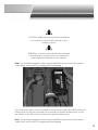
1
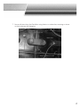
Information Solutions
Douglas
DataTrac™
Wireless Battery Data
Recorder and Transmitter
Installation and Operation Manual
June 2013
3-3005-44-01
If after carefully following the instructions in this manual, you have
difficulty installing or operating the product described, contact
technical support at www.DouglasBattery.com
Note
This document is based on information available at the time of its publication.
While efforts have been made to be accurate, the information contained herein
does not purport to cover all details or variations in hardware or software, nor to
provide for every possible contingency in connection with installation, operation, or
maintenance. Features may be described herein which are not present in all systems.
Aker Wade Power Technologies, LLC
4035 Hunterstand Court
Charlottesville, VA 22911
T 434.975.6001
F 434.975.0984
© Copyright 2013 Aker Wade Power Technologies, LLC. All rights reserved. All trademarks and logos are
the property of Aker Wade® except DataTrac™ and Douglas Data Manager™, which are trademarks of
EnerSys®. Subject to change without notice. E.&O.E.
2
Contents
Section 1: Introduction
4
4
5
5
Features and Capabilities
Data Available for Analysis
DataTrac Software Tools
Section 2: Specifications
Section 3: Safety Precautions
Section 4: Setup and Initialization
6
7
9
9
10
Configuring a PC to Communicate with the DataTrac
Testing Communications with the DataTrac
Initializing the DataTrac
Section 5: DataTrac Installation
For Battery Installation to Track Single-Battery Usage Data
Truck Installation for Tracking Throughput Measurements in Battery Change-Out Operations
Removing the DataTrac Unit for All Installations
Section 6: Optional Accessories
Section 7: Reading DataTrac Battery Data
Index
9
12
12
18
19
21
22
23
3
Section 1: Introduction
Connect the DataTrac and enhance your ability to manage battery usage,
maintenance and overall life. Start tracking daily usage, charge return,
temperature, water level and equalization events. With the DataTrac, you’ll collect
data needed to:
•
•
•
Confirm operator compliance charging and equalizing
Identify battery maintenance needs
Easily optimize fleet size and truck operation
Features and Capabilities
DataTrac is an intelligent battery data-collection device for use with industrial
battery applications. It contains instrumentation to continuously measure
temperature, current and voltage. DataTrac is available with a split-core current
transducer, for applications which require portability and with a solid core
transducer, which is designed to be installed permanently on a single battery for
long term energy metering applications. DataTrac has an internal sensor which it
uses to monitor temperature. It can also be configured with an external thermistor
which can be inserted between two battery cells, for more precise temperature
measurements. It can optionally be configured to monitor battery electrolyte level
and to drive a 24V solid-state relay.
DataTrac can have one or two serial ports. One serial port is used for host
communication and is typically configured with a Bluetooth® radio for wireless
communications but can also be configured as an RS232 port for communicating
with a truck based host computer. The other serial port may be used in some
applications to communicate with the charger via an isolated RS232 serial port.
It continuously monitors the state of the battery after being configured and
started by the user. Data is retained in onboard flash memory and events are
recorded detailing the operating condition of the battery. At all times the battery is
considered to be in one of three states:
•
•
•
Charging
Discharging
Idle
When DataTrac determines that the state of the battery has changed, an event
record is generated and stored that records the cumulative data of the state that
has just ended, and a new summary recording the data of the new state is started.
In addition, key high and low values measured during the operating state are
recorded with this event record.
® Bluetooth is a registered trademark of Bluetooth SIG, Inc.
4
Data Available For Analysis
• Start Time and Date, Total Time and Total Ampere hours for each charge profile
state (Charge, Discharge or Idle)
• Battery Temperature, voltage and electrolyte sensor level (for units with this
option installed) at beginning and end of each charge profile state
• Summaries for total plug-ins, average charge duration, average AHRs returned,
calculated daily and averaged over entire measurement period
• Battery or Truck Identification (Serial/ Model Number) can be configured on the
DataTrac for easy report identification
DataTrac data is divided into three types:
Configuration Data contains the data necessary to manage the operation of
DataTrac, including battery and truck serial numbers, battery configuration and put
in service date.
Event Data is a record of the operation of the battery to which DataTrac is
attached. Events are recorded for each operating state of the battery (charge,
discharge and idle). Event data is used to compile an accurate record of battery
use.
Summary Data contains aggregate usage data which is compiled by software
analysis tools.
DataTrac Software Tools
The Douglas Data Manager application software is used to configure the DataTrac
and analyze the data that it collects. Douglas Data Manager communicates with
DataTrac via Bluetooth and compiles and displays the data in different formats for
the end users: analysis such as ampere hours returned, temperature over time and
SOC over time. Douglas Data Manager uses a standard SQL database to maintain
DataTrac data, so that it can be easily accessed by any third party application.
For more information on using Douglas Data Manager with DataTrac devices, see
the Douglas Data Manager User’s Manual.
5
Section 2: Specifications
Name
Description
Nominal Battery Voltage
24 V – 80 V
Operating Voltage
10 V – 110 V
Operating Temperature
-4º F – 158º F (-20º C – 70º C)
Bi-directional Current Measurement
Allows for throughput data collection using a Hall effect sensor which can measure +/- 600A
Voltage Measurement
Continuous monitoring of overall battery voltage. Can be installed on truck or battery
Temperature
Internal sensor or optional external thermistor
Electrolyte Level Detection
With optional electrolyte sensor
Interface
Bluetooth® communication
Real Time Clock
Time keeping and stamping of data
Data Collection
Upload data to PC or ExpressLink™ via Bluetooth®
Data Storage
4000 event log records
Wireless Range
Up to 100 meters
Power Consumption
1 Watt (integrated 950mWhr backup)
Protection
• Over voltage
• Reverse Polarity Protection
Packaging
• Water and acid resistant
• UL 94V-0
Physical Dimensions
5.0”L × 2.0”W ×1.2”H
Compliance
Classified by UL® to UL 583
Table 1. Specifications for DataTrac
® Bluetooth is a registered trademark of Bluetooth SIG, Inc.
6
Section 3: Safety Precautions
SAVE THESE INSTRUCTIONS
This manual contains important safety and operating instructions.
This danger symbol indicates that personnel must
practice safety procedures in order to prevent
equipment damage, bodily injury, or death.
CAUTION! Installation of DataTrac must be performed by qualified
personnel only.
CAUTION! Working in the vicinity of lead-acid batteries is dangerous.
Batteries can generate explosive gases during normal battery operation. For this
reason, it is of utmost importance that you read these instructions and follow them
exactly.
• Wear complete eye protection and clothing protection. Avoid touching eyes
while working near the battery.
• If battery acid contacts the skin or clothing, wash immediately with soap and
water. If acid enters eye, immediately flood eye with running cold water for a
minimum of 10 minutes and get medical attention immediately.
• Make sure that the area in which you are working is well ventilated.
• NEVER smoke or allow a spark or flame in vicinity of battery.
• Be extra cautious to reduce risk of dropping a metal tool onto battery. It is
capable of producing a spark or short-circuiting the battery or other electrical
part and causing an explosion
• Turn off all the electrical loads on the vehicle and set the brake before installing
or removing the DataTrac unit.
7
CONSERVER CES INSTRUCTIONS
Ce manuel comporte des consignes importantes de sécurité et
d’utilisation.
Ce symbole de danger indique que le personnel
doit suivre les procédures de sécurité de façon à
prévenir une détérioration de l’équipement, un
dommage corporel ou la mort.
ATTENTION! L’installation de L’DataTrac doit être effectuée
uniquement par du personnel qualifié.
ATTENTION! Travailler à proximité de batteries plomb-acide est
dangereux.
• Les batteries peuvent générer des gaz explosifs durant leur fonctionnement
normal. Pour cette raison, il est de la plus grande importance de lire ces
instructions et de les suivre à la lettre.
• Porter des lunettes de protection et une combinaison de protection. Éviter de se
toucher les yeux pendant le travail à proximité de la batterie.
• Si l’acide de la batterie entre en contact avec la peau ou les vêtements, laver
immédiatement avec du savon et de l’eau. Si l’acide entre dans l’œil, rincer
immédiatement abondamment à l’eau froide en la laissant couler pendant un
minimum de 10 minutes et consulter immédiatement un médecin.
• S’assurer que l’espace de travail est ventilé correctement.
• Ne JAMAIS fumer ou allumer d’étincelle ou de flamme à proximité de la
batterie.
• Être extrêmement prudent pour ne pas laisser tomber un outil en métal sur la
batterie. Ceci pourrait produire une étincelle ou un court-circuit au niveau de
la batterie ou d’un autre composant électrique et provoquer une explosion.
• Éteindre toutes les charges électriques sur le véhicule et serrer le frein à main
avant d’installer ou de retirer l’unité DataTrac.
8
Section 4: Setup and Initialization
Configuring a PC to Communicate with the DataTrac
To communicate with the DataTrac from a PC, the PC must have a Bluetooth
radio installed (supplied with the Douglas Data Manager product) and be running
the Douglas Data Manager software. Refer to the Douglas Data Manager User’s
Manual for installing the software and the Bluetooth radio.
Testing Communications with the DataTrac
To verify that PC can communicate with DataTrac, prior to installing the DataTrac
on a truck or battery:
1. Gather Tools: DataTrac unit, DC power supply with output of at least 12 volts and
no more than 100 volts (such as bench power supply or 12V DC transformer), PC
with Douglas Data Manager software and Bluetooth radio.
2. Attach the red wire power lead of the DataTrac unit to the positive connection
of the DC power supply and the black wire power lead to the negative
connection. Apply power to the DC supply.
3. The red and green LEDs will blink rapidly as the DataTrac unit powers up. After a
delay of several seconds, you will see the green light of the unit begin to blink,
indicating that it is collecting data and ready to communicate with a host PC.
Note:
Only the green LED should be blinking on the DataTrac unit. If the DataTrac unit
is configured with an Electrolyte level sensor and the sensor is either not installed
or detects a low Electrolyte level, the red LED will blink steadily. Any other blink
patterns are indicative of an error. If the unit displays any of the following LED
patterns, please call customer service:
• Red and green LED flashing simultaneously – Real time clock error (Battery may
need to be replaced)
• Red and green LED flashing alternating – Unit has not been calibrated or has lost
calibration
• Red LED flashing 3 short bursts, followed by long burst - hardware error.
9
Initializing DataTrac
Follow the instructions in the Douglas Data Manager User’s Manual for Creating an
Douglas Data Manager database and Configuring the DataTrac unit.
Once the unit has been configured, the “get current values” function can be used
to make sure that the unit is reading voltage, current and temperature properly.
If the DataTrac unit is being deployed in a new location, you may also want to
clear the event data on the unit. DataTrac can store 4087 charge/discharge
events, so it is generally not necessary to clear events.
10
If the DataTrac unit is being deployed in a new location, you may also want to
clear the event data on the unit. DataTrac can store 4087 charge/discharge
events, so it is generally not necessary to clear events.
Note: The internal temperature sensor of the DataTrac unit will usually read a
few degrees higher than the ambient temperature, because of a slight rise in
temperature from components inside the unit case.
Note: Generally it is a good idea to clear events when changing the Data Trac
time, to avoid confusion when reading event reports.
11
Section 5: DataTrac Installation
Installation of DataTrac must be performed by
qualified personnel only. Be sure to follow all
safety instructions described in Section 3.
L’installation de l’DataTrac doit être effectuée
uniquement par du personnel qualifié. S’assurer
de suivre toutes les consignes de sécurité
décrites dans la section 3.
Note: For dual lead batteries, make sure the Hall Effect goes around the positive
cable that is used for BOTH charging AND discharging.
Note: For all installation scenarios, the red LED on the DataTrac unit should always
be OFF. If it is ON or blinking, contact qualified service personnel.
For Battery Installation to Track Single-Battery Usage Data
1. Gather Tools, DataTrac unit, 2 (#6) self-tapping screws with ring terminals, 4” and
8” cable ties, 1/4” socket & ratchet or nut driver, 1A inline fuse, 1/8” drill bit and
drill.
2. Attach the Hall Effect transducer. For the solid core unit, remove the battery
SB, SBX or Euro connector and slide the positive battery cable through the Hall
Effect unit, so that the arrows on the HE unit point towards the positive battery
post.
12
CAUTION! Make sure that the battery lead does
not come into contact with any part of the
battery or truck.
ATTENTION! S’assurer que le plomb de la batterie
ne rentre pas en contact avec un composant
quelconque de la batterie ou du camion.
Note: For dual lead batteries, make sure the Hall Effect goes around the positive
cable that is used for BOTH charging AND discharging.
For the split core unit, it is not necessary to remove the battery SB or SBX connector.
Simply open the HE unit and snap it shut around the positive battery lead, so that
the arrows on the HE unit point towards the positive battery post.
Note: For dual lead batteries, make sure the Hall Effect goes around the positive
cable that is used for BOTH charging AND discharging.
13
3. Once the Hall Effect device has been secured around the positive battery
cable, lay the DataTrac unit on top of the battery, in a location where it will not
interfere with the normal operation of the truck or battery.
4. Connect Power. To attach the power leads to battery terminals, first drill a
pilot hole on the positive and negative battery terminals with a 1/8” drill bit. Be
careful to only drill into the lead a little at a time and then remove the excess
material from the bit. Place the red wire ring terminal over pre-drilled hole on
the positive terminal and secure by screwing in #6 self-tapping screw, use 1/4”
socket or nut driver. Repeat this procedure for the negative terminal.
14
CAUTION! A (1) Amp, 250V inline fuse must be
added at the termination point of the DataTrac
positive power connection, so that in the event
that the DataTrac power lead is damaged, it
does not create a possible current path.
ATTENTION! Un fusible en série de 250 V, 1 A
doit être ajouté au point de terminaison de la
connexion électrique positive de l’DataTrac,
afin qu’un passage de courant ne soit pas
créé dans le cas où le câble d’alimentation est
endommagé.
5. For units configured with external thermistor only - To install the thermistor, locate
a position near the middle of the battery between four cells. This location should
not have a metal plate running between the cells. Use the Phillips screwdriver to
make a small passage for the battery thermistor. Holding the battery thermistor
at the top, slide it down and into the passage made by the screwdriver.
15
6. For units configured with electrolyte level sensor only - To install the electrolyte
level sensor, drill a ½ inch diameter hole in the top of the cell to be monitored.
This must not be the first (lowest voltage) cell of the battery. Insert the level
sensor into the cell. Connect the blue return wire to the negative post of battery
cell which is immediately adjacent to, and 2V less than the cell with the sensor.
Note: Pay careful attention to the orientation of the cells when connecting the EL
sensor wires. The voltage across the two wires must not exceed 4V.
16
7. Secure all wires from the DataTrac using Velcro or cables ties, ensuring no loose
or slack wires are left hanging.
17
Truck Installation for Tracking Throughput Measurements in Battery Change-Out
Operations
1. Gather Tools, DataTrac unit, 2(#6) self-tapping screws with ring terminals, 4” and
8” cable ties, 1/4” socket and ratchet or nut driver, small Phillips screwdriver,
electrical tape.
2. Position the DataTrac on the lift truck in a location where it will not be damaged
nor create interference during normal operation and battery change-out.
3. Attach the Hall Effect transducer. For the solid core unit, remove the SB
connector that goes to the battery, and slide the positive cable through the Hall
Effect unit, so that the arrows on the HE unit point towards the positive battery
post. For the split core unit, clamp the Hall effect sensor around the positive
cable of the truck. You will feel a “click” as the two halves of the Hall Effect
sensor snap together.
4. Attach the DataTrac power leads to a terminal block where the battery leads
are terminated. For front panel truck harness installation, make sure that if there
is a truck kill switch, that the DataTrac is installed between the kill switch and
battery (otherwise, if the kill switch is hit, the DataTrac will record that a battery
change out occurred).
5. Secure all wires from the DataTrac, using Velcro or cables ties, ensuring no loose
or slack wires are left hanging.
18
Removing the DataTrac Unit – for All Installations
To move the DataTrac unit to a different truck or battery, follow the reverse of the
instructions for installation. To remove a solid core Hall Effect sensor, remove the SB,
SBX or Euro connector and slide the HE unit off the end of the cable.
CAUTION! Make sure that the battery lead does
not come into contact with any part of the
battery or truck.
ATTENTION! S’assurer que le plomb de la batterie
ne rentre pas en contact avec un composant
quelconque de la batterie ou du camion.
1. For the split core Hall Effect unit, insert a flat blade screwdriver into the pry point
at the side of the unit, where the two halves snap together.
19
2. Keeping the blade of the screwdriver against the pry point, raise the screwdriver
to unlock the two halves of the Hall effect unit 20
Section 6: Optional Accessories
DataTrac units may be special ordered with several additional options that allow it
to be used in custom applications. All of these optional accessories require custom
software on the DataTrac unit, which is typically only provided for high volume
custom applications. Contact your sales representative for more information.
External Relay connection – this connection can be used to sink up to 100mA, for
the purpose of driving a solid state relay. The control voltage of the relay must not
exceed 24V. An inline fuse with a rating of 100mA max, 24Vdc min must be added
by the installer between the relay connection and the relay.
21
Section 7: Reading DataTrac Battery Data
Once the DataTrac unit has been initialized, it will collect charge, discharge and
idle data for the battery during the daily operations of the equipment. After it
has been accumulating battery data, you can download this data at any time,
as long as the DataTrac unit is powered and within range of the PC. This can be
accomplished while the unit is still attached to the battery/truck, or by connecting
the DataTrac unit to a power supply at any time after it has been removed.
Follow the instructions in the Douglas Data Manager User’s Manual for transferring
data into an Douglas Data Manager data base and generating reports.
22
Index
A
Accessories 21
B
Battery Temperature 5
C
Communications between PC and DataTrac 9
Communications Interface 9
D
Data Available for Analysis 5
Data Collection 6
Data Storage Amount and Time 6
E
Electrolyte Level Sensor 16
Electrolyte Sensor 16
External Relay Connection 21
F
Features and Capabilities 4
H
Hall-Effect Sensor 12, 18
I
Initializing DataTrac 10
Installation of DataTrac 12
M
Douglas Data Manager 5
N
Nominal Battery Voltage 6
O
Operating Temperature 5
Operating Voltage 5
23
P
Power Consumption 5
Power Leads 14
R
Reading DataTrac Battery Data 22
Real Time Clock 9
Removing the DataTrac Unit 19
RS232 Host Communication Cable 21
S
Safety Precautions 7
Setup and Initialization 9
Software Tools for DataTrac 5
Specifications 6
T
Thermistor 15
Tracking Single-Battery Usage Data 4
Tracking Throughput Measurements in Battery Change-Out Operations 4
V
Voltage Measurement 6
24