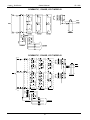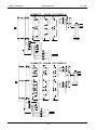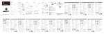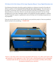
1
Models: LG1 & LG3 Legacy® Gold Series Battery Charger Owner’s Manual I.B. 1592 REV: A To be automatically connected to your closest Service Center, call us toll-free at: 1-800-DOUGLAS (1-800-368-4527) Or, visit us at: http://www.douglasbattery.com/ Model: Installed by: S/N: AC Input Voltage: Date: IMPORTANT Read and understand your user's manual before installing, operating, or servicing this product. DO NOT DESTROY THIS BOOK Legacy® Gold Series Owner’s Manual I.B. 1592 AC LINE VOLTAGE LETTER CODES The following table describes the code letters to be used in new charger part numbers to indicate the AC line voltage(s) and AC line frequency at which the charger can be operated. Code Letters Voltage(s) (volts rms.) Line Frequency (Hz) B A D J T* W* X* Y* 208/240/480 120/208/240 220/380/440 480/550/600 208 240 240/480 480 SPECIAL VOLTAGES 60 60 50 60 60 60 60 60 UNSPECIFIED Comments Applicable to all charger families; single or three phase chargers. Applicable to all charger families; single phase chargers only. Applicable to all charger families; single or three phase chargers. Applicable to all charger families; single or three phase chargers. Use only for special designs; single or three phase. Use only for special designs; single or three phase. Use only for special designs; single or three phase. Use only for special designs; single or three phase. Use only for special designs; Contact the plant for further information. * Replacement part numbers for chargers with such letter codes shall be referred to the charger's tables with code letter "B" SPECIALTY CHARGER OPTIONS LIST Check items included () Suffix C6 C8 C10 C12 CF CF12 CR D HD3 HD4 L13 L15 L18 L20 L25 L30 P PP Q S T WF WFB WR WGF Description Kit part #** 6’ of #10AWG AC Cord with 30 AMP Plug.* (3ph) X225-77-2 (1ph) X225-77-4 8' of #10AWG AC Cord with 30 AMP Plug.* N/A 10' of #10AWG AC Cord with 30 AMP Plug.* N/A 12' of #10AWG AC Cord with 30 AMP Plug.* N/A 10’ of #8AWG AC Cord with 50 AMP Plug.* N/A 12’ of #8AWG AC Cord with 50 AMP Plug.* N/A 6’ of #10AWG AC Cord with 30 AMP Plug and 30AMP receptacle.* (3ph) X225-77-1 (1ph) X225-77-3 Charger with AC Disconnect Switch. 6’ of #10AWG AC Cord with 30 AMP Plug.* (3ph) X225-77-2 (1ph) X225-77-4 6’ of #10AWG AC Cord with 30 AMP Plug and Receptacle.* (3ph) X225-77-1 (1ph) X225-77-3 13' of DC cable. See OUTPUT CABLE 15' of DC cable. See OUTPUT CABLE 18' of DC cable. See OUTPUT CABLE 20' of DC cable. See OUTPUT CABLE 25' of DC cable. See OUTPUT CABLE 30' of DC cable. See OUTPUT CABLE Parallel DC cables, standard size. N/A Charger shipped on a Plastic Pallet N/A AC input change Quick Tap™ N/A Series DC cables N/A Block Out Timer switch. Ferro Charger with WaterGenius P/N 1003 position front Ferro Charger with WaterGenius P/N 1003 position front, DC cables through bottom. Ferro Charger with WaterGenius P/N 1006 position right Ferro Charger with WaterGenius P/N 1006 position front (door) Stacking Hardware Kit** X225-99-0-2 Wall Mounting Brackets** X225-99-0-1 *When AC cord is installed at the factory only one input voltage is marked on the charger. **Accessories Note: refer specialty charger part numbers to the standard models contained in this manual. 1 Legacy® Gold Series Owner’s Manual I.B. 1592 TABLE OF CONTENTS AC LINE VOLTAGE LETTER CODES .....................................................................................................................................................1 SPECIALTY CHARGER OPTIONS LIST .................................................................................................................................................1 IMPORTANT SAFETY INSTRUCTIONS ..................................................................................................................................................3 TECHNICAL INFORMATION ...................................................................................................................................................................4 INSTALLATION ........................................................................................................................................................................................5 LOCATION........................................................................................................................................................................................5 Stacking Multiple Chargers .......................................................................................................................................................5 ELECTRICAL CONNECTIONS ........................................................................................................................................................5 On single phase units ...............................................................................................................................................................5 On three phase units.................................................................................................................................................................5 Connecting Input Power............................................................................................................................................................6 AC Disconnect ..........................................................................................................................................................................6 Plug Polarity..............................................................................................................................................................................6 Grounding the Charger .............................................................................................................................................................6 DESCRIPTION OF OPERATION .............................................................................................................................................................6 GENERAL .........................................................................................................................................................................................6 BEGINNING THE CHARGING .........................................................................................................................................................6 CHARGING.......................................................................................................................................................................................6 POWER DIODES..............................................................................................................................................................................6 AC POWER FAIL ..............................................................................................................................................................................6 PARALLEL CHARGING (OPTIONAL) ..............................................................................................................................................7 SERIES CHARGING (OPTIONAL) ...................................................................................................................................................7 AC DISCONNECT (OPTIONAL).......................................................................................................................................................7 TM AC INPUT CHANGE QUICK TAP (OPTIONAL)............................................................................................................................7 OPERATING INSTRUCTIONS .................................................................................................................................................................7 CONTROL BOARD ..................................................................................................................................................................................7 NORMAL OPERATION.....................................................................................................................................................................7 CHARGER FEATURES ....................................................................................................................................................................8 Auto Start/Delayed Start ...........................................................................................................................................................8 Auto Equalize Cycle..................................................................................................................................................................8 Manual Equalize Cycle .............................................................................................................................................................8 Refresh Cycle ...........................................................................................................................................................................8 Cool Down ................................................................................................................................................................................8 USER PARAMETER CONFIGURATION..........................................................................................................................................9 Adjusting Parameter Settings ...................................................................................................................................................9 DEFAULT SETTINGS.......................................................................................................................................................................9 CHARGER FAULTS .........................................................................................................................................................................10 VOLTAGE CONVERSION........................................................................................................................................................................10 AC INPUT CHANGE (STANDARD)..................................................................................................................................................10 3PH Wiring Conn. Chart ...........................................................................................................................................................11 1PH Wiring Conn. Chart ...........................................................................................................................................................11 TM AC INPUT CHANGE WITH QUICK TAP .......................................................................................................................................12 1PH & 3PH Wiring Conn. Illustration ........................................................................................................................................12 MAINTENANCE & SERVICE ...................................................................................................................................................................12 COMMON REPLACEMENT PARTS ........................................................................................................................................................13 SHUNT & DC FUSES .......................................................................................................................................................................16 Shunt, 1PH & 3PH ....................................................................................................................................................................16 DC Fuse, 1PH & 3PH ...............................................................................................................................................................16 AC INPUT & FUSES .........................................................................................................................................................................16 3PH Volt Model B (208/240/480 V)...........................................................................................................................................16 1PH Volt Model B (208/240/480 V)...........................................................................................................................................16 3PH Volt model D (220/380/440 V) ..........................................................................................................................................17 3PH Volt model J (480/550/600 V) ..........................................................................................................................................17 1PH Volt model D (220/380/440 V) ..........................................................................................................................................18 1PH Volt model J (480/550/600 V) ..........................................................................................................................................18 1PH Volt model A (120/208/240 V) ..........................................................................................................................................18 OUTPUT CABLE REPLACEMENT ..........................................................................................................................................................19 1PH STANDARD WIRING........................................................................................................................................................................20 3PH STANDARD WIRING........................................................................................................................................................................20 SCHEMATIC, 1 PH, VOLT MODEL B......................................................................................................................................................21 SCHEMATIC, 3 PH, VOLT MODEL B......................................................................................................................................................21 SCHEMATIC, 1 PH, VOLT MODEL D......................................................................................................................................................22 SCHEMATIC, 3 PH, VOLT MODEL D......................................................................................................................................................22 SCHEMATIC, 1 PH, VOLT MODEL J ......................................................................................................................................................23 SCHEMATIC, 3 PH, VOLT MODEL J ......................................................................................................................................................23 SCHEMATIC, 1 PH, VOLT MODEL A......................................................................................................................................................24 MAINTENANCE LOG ...............................................................................................................................................................................25 2 Legacy® Gold Series Owner’s Manual I.B. 1592 IMPORTANT SAFETY INSTRUCTIONS 1) 2) 3) 4) 5) 6) 7) 8) 9) 10) 11) 12) 13) This manual contains important safety and operating instructions. Before using the battery charger, read all instructions, cautions, and warnings on the battery charger, the battery, and the product using the battery. These chargers are designed to charge industrial flooded lead-acid batteries. Read and understand all setup and operating instructions before using the battery charger to prevent damage to the battery and to the charger. Do not touch non-insulated parts of the output connector or the battery terminals to prevent electrical shock. During charge, batteries product hydrogen gas, which can explode if ignited. Never smoke, use an open flame, or create sparks in the vicinity of the battery. Ventilate well when the battery is in an enclosed space. Do not connect or disconnect the battery plug while the charger is on. Doing so will cause arcing and burning of the connector resulting in charger damage or battery explosion. Lead-acid batteries contain sulfuric acid, which causes burns. Do not get in eyes, on skin, or on clothing. In cases of contact with eyes, flush immediately with clean water for 15 minutes. Seek medical attention immediately. Only factory qualified personnel can service this equipment. For service, contact the nearest Douglas Battery authorized representative at: 1-866-443-9433. De-energize all AC and DC power connections before servicing the charger. This charger is not for outdoor use. Do not expose the charger to moisture. Operating conditions should be 0° to 104°F; 0 to 70% relative humidity. Do not operate the charger if it has been dropped, received a sharp hit, or otherwise damaged in any way. For continued protection and to reduce the risk of fire, install chargers on a floor of non-combustible material such as stone, brick, or grounded metal. WARNING: The shipping pallet must be removed for proper and safe operation. INSTRUCTIONS DE SÉCURITÉ IMPORTANTES 1. 2. 3. 4. 5. 6. 7. 8. 9. 10. 11. 12. 13. Ce manuel contient des informations et des consignes importantes pour l’installation et l’utilisation du chargeur de batteries industrielles. Avant tout emploi, il est fortement conseillé de lire l’ensemble des instructions, recommandations, et avertissements concernant le chargeur et la batterie. Ce chargeur a été conçu pour la charge des batteries industrielles de type plomb-acide dites « ouverte ». (il ne peut pas être adapté pour les batteries étanches.) Lisez toutes les consignes d’installation et d’utilisation avant d’employer le chargeur de batteries afin de prévenir tout dommage envers la batterie et/ou le chargeur. Ne pas se mettre en contact avec les pièces sous-tension non-isolées tels que la prise de charge ou les éléments de connexion de la batterie pour empêcher tout choc électrique. Pendant la charge, le dégagement d’hydrogène rend l’emploi de feu strictement interdit: « risque d’explosion ». Ne jamais fumer, employer une flamme nue ou créer d’étincelles à proximité de la batterie. Ventiler suffisamment le local de charge pour éviter toute condensation de gaz dans un espace restreint. Ne brancher ou débrancher la batterie que si le chargeur est à l’arrêt. Procéder ainsi permet d’éviter d’endommager la prise de charge et de causer des dommages au chargeur ou l’explosion de la batterie. Les batteries d’acide que plomb contiennent de l’acide sulfurique pouvant causer des brûlures. Eviter le contact avec les yeux, la peau ou les vêtements. Dans le cas d’un contact avec les yeux, rincer aussitôt avec de l’eau propre pendant 15 minutes et consulter un médecin immédiatement. Seul le personnel qualifié par l’usine peut entretenir cet équipement. Avant toute intervention d’entretien ou de réparation, il est impératif de s’assurer que le chargeur est hors tension ainsi que la batterie déconnectée du chargeur. Le chargeur n’est pas conçu pour fonctionner en usage extérieur. Ne pas exposez le chargeur à l’humidité. Les conditions de fonctionnement doit être comprise entre -15° et + 40°C avec une humidité relative de 0 â de 70%. Ne pas mettre en fonctionnement le chargeur s’il a reçu un choc mécanique ou tout autre dommage de quelque façon. Pour une protection permanente et pour réduire le risque du feu, installez les chargeurs sur un plancher ou un matériel non-combustible tel qu’un mur plein en béton, en brique ou l’acier. 3 Legacy® Gold Series Owner’s Manual I.B. 1592 TECHNICAL INFORMATION The nameplate, located on the outside of the charger, should be used to check this application before installation. Part Number This number specifies in general the characteristics of this particular charger and for this reason it is required in any discussion or correspondence regarding this unit. MBP-CC-AAA(A)VOOOO Model type PC Board type Phase Cell capacity Ampere hour (3 - 4 digits) Volt code Option(s) Serial Number This number indicates complete information about the specific charger. It must be supplied with the part number on any correspondence or discussion regarding this charger. Battery Type The chemical content construction of the battery this unit is designed to charge is given in this part of the nameplate. (L-A = Flooded Lead-Acid) Ampere-Hours The information supplied here is the ampere-hour battery capacity which this unit has been factory adjusted to recharge. Charging batteries of ampere-hour capacities not specified here might cause the charger to deviate from the specifications. Cells This portion of the nameplate gives the number of cells this unit will charge. This number must match exactly with any battery connected to the charger output. Input AC Volts The nameplate shows the input voltage(s) accommodated by this charger. IMPORTANT: The charger will operate only on nominal line voltages stamped on the nameplate. Failure to select the correct voltage will result in damage to the charger and/or the battery. The Voltage Conversion section of this manual provides jumper settings for a specific input voltage. Input AC Amps The external fusing and/or the line disconnect circuit breaker should be as specified in the National Electrical Code. (AC fuse values can be found on the decal inside the charger). Hz This gives the frequency in cycles per second of the AC input voltage. Under no conditions operate charger at a different frequency or from a generator with unstable frequency. Phase Number "1" indicates a Single Phase Charger Number "3" indicates a Three Phase Charger. A single phase charger can be operated from a single phase line, or from two lines of a three phase line, provided that the line voltage is correct. DC Volts This gives the nominal DC output voltage of the system. Rated DC Amps This is the nominal DC value of current that this unit will deliver to a battery that is 100% discharged. 4 Legacy® Gold Series Owner’s Manual I.B. 1592 INSTALLATION WARNING: The shipping pallet must be removed for proper and safe operation. Location For maximum trouble-free service, choose a location which is free of excess moisture, dust, and corrosive fumes. Also, avoid locations where temperatures are high or where liquids will drip on the charger. Allow six (6) inches of clearance at rear and sides of the charger for air circulation. Do not obstruct the ventilating openings or the space under the charger. Stacking Multiple Chargers These chargers can be stacked up to a maximum of 3 units high. Chargers are not designed to be stacked side by side due to ventilation requirements. 18.63 .88 Single Phase chargers require holes drilled on the top. Use drawing template for drills. 3.91 Ø.56 (TYP X4) 1. Position the first charger so that a minimum of 6 inches of space is between the charger and any wall, and 12 inches between the charger and any other equipment. 25.06 17.25 2. Place the second charger on top of the first. Align the bolt holes on each charger. 3. Fasten both charger cabinets together securely using 3/8” bolts and nuts. NOTE: the two bolts toward the back of the charger may be omitted if an after market metal strap (about 8 inches) is used to secure both chargers. Remove existing 1/4" screws of the chargers' sides and attach strap with screws. Refer to picture. Hardware kit # X225-99-0-2 can be ordered to attach two chargers. 16.88 4. Repeat steps 2 and 3 for the third charger. 5. Stacked chargers must be fastened to the wall using devices suitable for the wall construction and the bolt holes at the top of the highest charger. NOTE: Ambient temperature at all levels cannot exceed 104OF / 40OC. METAL STRAP Electrical Connections To prevent failure of the charger, be sure it is connected to the correct line voltage. Single phase units: Connect power to the charger as follows: Phase A to L1 (fuse block) Phase C to L2 (fuse block) TWO STACKED CHARGERS, RIGHT SIDE VIEW Three phase units: Connect all the chargers as follows: Phase A to L1 (fuse block) Phase B to L2 (fuse block) Phase C to L3 (fuse block) 5 Legacy® Gold Series Owner’s Manual I.B. 1592 Connecting Input Power WARNING: Make sure the disconnect is in the OFF position and the battery is disconnected before connecting the input power to the terminals of the charger. Connect the input power to the appropriate terminals, including ground. Follow your local electrical or National Electric Code in making these connections. The figure that follows shows both the top and right side installation options for routing the incoming power cable. IMPORTANT: When the AC Disconnect Switch is factory installed connect the input power to the Switch instead the AC fuse block. AC Disconnect The user must provide suitable branch circuit protection and a disconnect method from the AC power supply to the charger to allow for safe servicing. (Even if the charger has an optional factory installed Disconnect Switch) Plug Polarity The charging cable is connected to the DC output of the charger with the positive lead marked RED. The output polarity of the charger must be strictly observed when connecting to the battery (read warning above). Improper connection will open the DC fuse. Grounding the Charger DANGER: FAILURE TO GROUND THE CHARGER COULD LEAD TO FATAL ELECTRIC SHOCK. Follow local codes or National Electric Code for ground wire sizing. Connect a grounding conductor to the lug provided on the horizontal support panel. This lug is marked as shown: DESCRIPTION OF OPERATION General This battery charger is designed to charge flooded lead-acid storage batteries only of the cell and ampere-hour rating as marked on the nameplate. Beginning the Charging When a battery is connected to the charger, the control board senses voltage and after a 5 second delay, the charger energizes. During this delay the CHARGING LED flashes. NOTE: For Deluxe type of chargers; a programmable Auto Start delay can be set anywhere from 0 up to 25 hours. Read more about each type of charger under the heading OPERATING INSTRUCTIONS Charging Charging current is determined by the battery voltage and interaction of the ferroresonant charger. Charging current tapers automatically as battery voltage rises during the charge. As the battery charges, the LED bar graph will display the percentage of battery capacity. Power Diodes The power diodes rectify the output of the ferroresonant transformer. AC Power Fail The charger will not detect an AC power fault or AC fuse open. If the AC power fails with a battery connected to the charger during a charge cycle, the charger will reset and start a new charge cycle when power is restored. 6 Legacy® Gold Series Owner’s Manual I.B. 1592 Parallel Charging (Optional) Available for Deluxe chargers only (Auto Start delay is required) In parallel charging, batteries must have an equal number of cells and must match the charger nameplate’s ratings. Ampere-Hour rating of charger must be equal to the ampere-hour of both batteries combined. Theoretically, charging current is equally divided between both batteries provided that batteries % of discharge and ages are equal. Make sure both batteries are connected before charge cycle starts. Series Charging (Optional) In series charging, the voltages of both batteries add up and must match charger’s nameplate rating. Charger’s ampere-hour rating must be equal to each of the batteries ampere-hour rating. Charge cycle will not start unless both batteries are connected. AC Disconnect (Optional) When an AC disconnect is installed, access to the charger through the front door is denied unless the AC disconnect is switched off. When the AC disconnect is in the off position, power is only present at the disconnect switch input terminals. Make sure that main breaker is switched off before working on the charger. AC Input Change Quick Tap™ (Optional) Quick Tap™ is a feature to Douglas chargers that allows the user to change AC input easily and quickly. See the heading VOLTAGE CONVERSION for more information. OPERATING INSTRUCTIONS Read operating Instructions for the type of control board that matches your charger. CONTROL BOARD Normal Operation 1. Make sure that the battery is properly matched for the particular charger. For charger characteristics refer to the nameplate label located on the front panel of the charger. Failure to properly match charger and battery can result in damage to both. 2. Idle Mode: When AC input voltage is applied to the charger and no battery is connected, the POWER LED will be lit. This message will display in rotation on the front panel display: Conn Batt 3. During Idle Mode, toggling the UP or DOWN pushbuttons will display the previous charge cycle parameters. Toggle the UP or DOWN to display the total charge time, ampere-hours delivered, highest voltage during the previous charge cycle, the number of charge cycles since the last equalize and the equalize count. Only the charge count and equalize count remains in non-volatile memory. These values will be saved even when AC power is removed. The other values will remain in volatile memory until the next charge cycle begins or if AC power is removed. 4. Plug the battery connector into the charger connector. Once the battery is connected to the charger, the START/STOP LED will flash for approximately 5 seconds while the display shows this message: Strt ## Cells The contactor will engage and charging will begin. The START/STOP LED will light steadily, the LED bar graph will indicate the percent charged status of the battery and the display will now begin to show: ####. # (Charger output current) #### (Ampere-hours returned) ##. ## (Time) #. ### (Cell Voltage) These values are displayed in rotation for about 2 seconds each. The display can be changed so that current or voltage, or current and voltage or all the above will be displayed. The default setting is for all the above to be displayed. 7 Legacy® Gold Series Owner’s Manual I.B. 1592 CAUTION: To prevent arcing and burning at the connector and possible battery explosion, press the START/STOP pushbutton first to stop the charge cycle before removing a battery that is currently on charge. 5. When the battery reaches Gassing Voltage, the yellow 80% LED will light. 6. When the battery is fully charged the green CHARGE COMPLETE LED will light, the START/STOP LED will extinguish and the charger will shut off. At this time the battery is at full capacity and ready for use. Charger Features Auto Start/Delayed Start Auto Start enables the battery charger to start the charge cycle automatically after the battery is connected to the charger. A programmable delay can be programmed so that Auto Start will begin after a set time period. This delay can be set through the front panel display, refer to d - S t in section User Parameter Configuration. Auto start can be delayed anywhere from 0 up to 25 hours, in one minute intervals. Auto Equalize Cycle An Equalize Cycle adds a predetermined amount of time to extend the battery's charge cycle. This charger is equipped with an Auto Equalize function. This is a configurable parameter, consult your service representative for more information. The factory default setting for the Auto Equalize cycle is 3 hours of charge time for every fifth charge cycle. A charge cycle consists of at least one hour of continuous charging of the battery by the charger. Every time the battery completes a charge cycle, the charge counter is incremented. When the charge counter reaches the programmed Equalize count value, an equalize cycle will occur immediately after the battery completes its normal charge cycle. When an equalize charge cycle is pending, the EQUALIZE LED will flash. The equalize button can be pressed at any time during the normal charge cycle to stop the pending equalize cycle. Once the battery has completed a successful charge cycle, the Charge Complete LED will light and the charger will immediately go into the equalize charge cycle. The EQUALIZE LED will then light steadily. Pressing the EQUALIZE button during the equalize charge cycle will have no effect on the charger. Manual Equalize Cycle With this charger, the battery can also be equalized manually. Pressing the EQUALIZE button at any time during the charge cycle will activate the equalize function. Once pressed, the EQUALIZE LED will begin to flash indicating that an equalize cycle will occur once the battery has completed a successful charge cycle. The EQUALIZE button can again be pressed at any time during the normal charge cycle to stop the pending equalize cycle. The CHARGE counter is reset every time the battery completes a successful Equalize charge cycle. Pressing the EQUALIZE button during the Equalize charge cycle will have no effect on the charger. NOTE: Since Equalize charging extends the recharge time, it is best to do this when additional cooling time is available (example: on a weekend). Consult your factory representative to determine Equalize intervals that meet your needs. Refresh Cycle If a battery remains connected to the charger for a predetermined amount of time after a charge cycle has been completed, a Refresh charge cycle will be given to the battery. The factory default setting for the Refresh Cycle is to refresh for 20 minutes every 12 hours. This is a configurable parameter, consult your service representative for more information. Cool Down When a battery completes a charge cycle without error, it ideally should cool down before being used. This is a configurable parameter that can be set through the front panel display, refer to c o o L in section User Parameter Configuration. The factory default setting for the Cool Down is 1 hour. 8 Legacy® Gold Series Owner’s Manual I.B. 1592 User Parameter Configuration Adjusting Parameter Settings The charger's user parameters may be configured only while the charger is in idle mode. In order to do so, press the EQUALIZE pushbutton and hold for approximately five seconds. The display will read USEr and is now ready for user parameter configuration. When you release the EQUALIZE pushbutton the display will then read diSP. For a list of available user parameters and their definitions, see the table below. You can scroll up through the different parameters by using the EQUALIZE pushbutton. In order to adjust the parameters press the UP or DOWN pushbuttons. If you press and hold the UP or DOWN pushbuttons for 3 seconds when adjusting the parameters, the options will scroll through at a rapid pace. Release the pushbutton to return to normal scrolling mode. When finished adjusting parameters, press the START/STOP pushbutton to exit the user parameter configuration mode and save the parameter settings. The display will now read CONN BATT. Parameter diSP d-St CooL EU-C Description Display mode 3 = displays current, ampere-hours returned, charge time and battery voltage 2 = displays current and voltage only 1 = displays current only 0 = displays voltage only Delayed start Amount of time delay after a battery is connected to the charger before charging proceeds. Increments in 1 minute intervals. Cool Down Time Amount of time after a complete charge cycle that a battery needs to cool down before being utilized. Equalize Count Total amount of charge cycles that need to occur before an automatic equalize charge cycle will take place. ( 0 indicates that no Equalize charge will occur) Range Default 0-3 3 0 min 25 hr. .00 0 hr. - 12 hr. 1.00 hr 0 - 20 charge cycles 5 charge cycles Default Settings Resetting default parameters is not recommended and could seriously affect charger/battery performance. Consult your local service representative for further information on charger settings. 9 Legacy® Gold Series Owner’s Manual I.B. 1592 Charger Faults The charger control circuitry constantly monitors for several fault conditions. If a fault should occur, the charge in progress is interrupted, and a fault message is displayed on the front panel. A list of the faults and their descriptions follow. Displayed Fault Description Fault LED Occurs when the DC fuse opens because of an excess of current. Call Service - YES Bar Graph - Flashes dC FuSE t-1 Err Occurs when a charging battery is disconnected from the charger without first stopping the charge cycle. Occurs when the time limit to gassing voltage is exceeded. t-2 Err Occurs when the overall charge cycle time limit is exceeded. OPEn batt Lo batt Hi batt Occurs when the battery is first connected and the voltage is between 1.0 and 1.8 Volts/cell.* Occurs when the battery is first connected and the voltage is above 2.4 Volts/cell. Occurs when there is negative change in battery voltage. Call Service - NO Bar Graph - Steady On Call Service - NO Bar Graph - Steady On Call Service - NO Bar Graph - Steady On Call Service - NO Bar Graph - Steady On Call Service - NO Bar Graph - Steady On Fault Clearing Can be reset by disconnecting the battery from the charger. Replace Fuse. Can be reset by connecting a battery to the charger. Can be reset by disconnecting the battery from the charger. Can be reset by disconnecting the battery from the charger. Can be reset if battery voltage is between 1.8 and 2.4 Volts/cell Can be reset if battery voltage is between 1.8 and 2.4 Volts/cell Can be reset by Call Service - NO disconnecting the battery Bar Graph - Steady On from the charger. Hot batt * If battery voltage is below 1.0 Volt/cell, the charger will not recognize that a battery has been connected. The display will continue to read Conn Batt. VOLTAGE CONVERSION The charger is designed to operate from nominal line voltages as marked on the nameplate. The line voltage to which the charger is to be converted must be one of the voltages shown on the charger nameplate. DANGER: POWER MUST BE DISCONNECTED BEFORE CHANGING AC INPUT CONNECTIONS. THERE ARE DANGEROUS VOLTAGES WITHIN THE BATTERY CHARGER CABINET. ONLY QUALIFIED PERSONNEL SHOULD ATTEMPT TO ADJUST OR SERVICE THIS BATTERY CHARGER AC Input change (Standard) NOTE: Chargers with optional Quick Tap™ please refer to AC Input Change With Quick Tap™. CAUTION: 1. Change AC fuses to the value of the desired line voltage available for this charger. (AC fuse values can be found on the decal inside the charger). 2. Change jumper "L1/V" (red wire), at terminals of the Control Transformer's Primary fuse, to desired line voltage. CAUTION: Failure to perform this step may cause the Control Trans. Primary fuse to open. 10 Legacy® Gold Series Owner’s Manual I.B. 1592 3. Change provided jumpers, on the main transformer primary tap location, as shown on the decal inside the door of the charger, or on the following charts. (Jumpers not being used are stored in the manual's envelope inside the charger). 4. Indicate the line voltage change on the decal inside the charger. 1PH. Wiring Conn. Chart 3PH. Wiring Conn. Chart 11 Legacy® Gold Series Owner’s Manual I.B. 1592 AC Input Change with Quick Tap™ If available CAUTION: CONNECTOR IS KEYED AND PINS ARE FRAGILE. 1. Change AC fuses to the value of the desired line voltage available for this charger. (AC fuse values can be found on the decal inside the charger). 2. Change Quick Tap™ plug to the desired line voltage as marked under the sockets. 3. Indicate the line voltage change on the decal inside the charger. 1PH. and 3PH. Wiring Conn. Illustration Quick Tap Wire Assembly Part Numbers Voltage Model B D J A 1Ph. QT Part Number X1106-99-F1B X1106-99-F1D X1106-99-F1J X1106-99-F1A 3Ph. QT Part Number X1106-99-F3B X1106-99-F3D X1106-99-F3J N/A MAINTENANCE & SERVICE The charger requires a minimum of maintenance. Connections and terminals should be kept clean and tight. The unit should be periodically cleaned with an air hose to prevent any excessive dirt build up on components. Care should be taken not to bump or move any adjustments during cleaning. Make sure that both the AC lines and the battery are disconnected before cleaning. The frequency of this type of maintenance depends on the environment in which this unit is installed. To be automatically connected to your closest Service Center call us toll-free at: 1-800-DOUGLAS (1-800-368-4527) Or visit us at: http://www.douglas.com/ 12 Legacy® Gold Series Owner’s Manual I.B. 1592 REPLACEMENT PARTS CIRCUIT BOARDS: Gold Series X1060-99-DGF-1 BASE KITS: KIT DESCRIPTION 10” BETWEEN XMR BRACKETS 12” BETWEEN XFMR BRACKETS SINGLE PHASE PARTS: DESCRIPTION DOOR CAPACITOR PANEL TERMINAL BOARD “QT-E” CONTROL TRANSFORMER MODEL A THREE PHASE PARTS DESCRIPTION DOOR BACK TERMINAL BOARD “A” TERMINAL BOARD “C” (CAPACITOR) TERMINAL BOARD “QT-A” DC CABLE CLAMP (4/0) 1PH X225-99-1-10 X225-99-1-12 PART NUMBER X054-99-1-6B X052-99-1-2 256-99-11 X127-99-1A DESCRIPTION TOP/BACK TERMINAL BOARD “E” TERMINAL BOARD (CAPACITOR) PART NUMBER X057-99-1-1B 256-99-8 256-99-5 PART NUMBER X054-99-3-17B X057-99-3-16B 256-99-3 256-99-6 DESCRIPTION TOP CAPACITOR PANEL TERMINAL BOARD “B” TERMINAL BOARD “D” (CAPACITOR) TERMINAL BOARD “QTB” PART NUMBER X052-99-3-12B X052-99-3-7 256-99-4 256-99-7 256-99-9 356-5-16 PARTS COMMON TO SINGLE AND THREE PHASE DESCRIPTION PART NUMBER LEFT SIDE X057-99-0-7B UPRIGHT X052-99-0-6 LATCH RIVETS 164-8-6 TERMINAL BOARD “KTK” FUSE REDUCER (<70A W/100A FUSE BLOCK) GROUND LUG CONTROL TRANSFORMER, MODEL B CONTROL TRANSFORMER, MODEL J FUSE, F5, “KTK” TERMINAL BOARD MODEL J CONTACTOR (40A) 3PH X225-99-3-10 X225-99-3-12 256-99-1 X014-17-6 X012-7-24 X127-99-2B X127-99-4J X014-34-7 X129-62-53 13 256-99-10 DESCRIPTION RIGHT SIDE DOOR LATCH DC CABLE CLAMP (#2, 1/0, 2/0, 3/0) TERMINAL BOARD “3AG” FUSE REDUCER (<40A W/60A FUSE BLOCK) CAPACITOR BRACKET CONTROL TRANSFORMER, MODEL D FUSE, F5, “KTK” TERMINAL BOARD, MODEL B AND D FUSE F6, F7, F8 “3AG” TERMINAL BOARD PART NUMBER X057-99-0-6B X044-1-32 356-5-15 CONTACTOR (60A) X129-62-54 256-99-16 X014-17-5 029-99-B X127-99-3D X014-34-5 X014-7-28 Legacy® Gold Series Owner’s Manual I.B. 1592 Note: The illustration below identifies the location of some important components in 1ph. and 3ph. Standard Chargers. The component P/N may vary from charger to charger. (For a P/N, refer to the 'Replacement Parts' tables). ITEM # 1 2 3 4 5 6 7 8 9 10 11 12 13 14 15 16 17 18 19 20 21 22 23 24 25 26 27 28 29 W-1 W-2 W-3 W-4 DESCRIPTION Control transformer PC Board Fuses Contactor Primary fuse, Control transformer Terminal Board Primary, Main Transformer AC Block / Input Fuses Terminal Board Primary, Main Transformer Capacitor Terminal Board Secondary, Main Trans. Terminal Board Secondary, Main Trans. Capacitor Heat Sink / Rectifier Assembly Shunt DC Fuse DC Output Cables & DC Cable Clamp Panel, Sub-assembly Panel, Capacitor Cross Member, Heat Sink Cabinet, Base Cabinet, Right side Cabinet, Top/Back Door Cabinet, Left side Main Transformer, Teaser Main Transformer, Primary Cross Member, Main Transformers Upright Ground Lug Brackets, Capacitors Wire Group, Primary Voltage Wire Group, Capacitors Wire Group, PC Board Cable Connecting Heat Sink & Shunt 14 Legacy® Gold Series Owner’s Manual 15 I.B. 1592 Legacy® Gold Series Owner’s Manual I.B. 1592 Replacement part numbers for chargers with letter codes "T", "W", "X", and "Y" shall be referred to the charger's tables with code letter "B" AC Input & Fuses 1PH, Volt Model B (208/240/480 V.) 3PH, Volt Model B (208/240/480 V.) 1 Phase; Model B AC FUSES 3 Phase; Model B AC FUSES 208 Volts 240 Volts 480 Volts I AC Value Model I AC Value 208 Volts Model P/N I AC Value P/N I AC Value P/N 6-550 5.3 10 X014-99-10 4.6 10 X014-99-10 2.3 6 X014-99-6 6-600 5.8 12 X014-99-12 5.0 10 X014-99-10 2.5 6 X014-99-6 6-775 7.5 15 X014-99-15 6.5 12 X014-99-12 3.3 6 X014-99-6 240 Volts P/N I AC Value 480 Volts P/N I AC Value P/N 6-225 3.8 8 X014-99-8 3.3 6 X014-99-6 1.6 3 X014-99-3 6-380 6.4 12 X014-99-12 5.5 10 X014-99-10 2.8 6 X014-99-6 6-450 7.5 15 X014-99-15 6.5 12 X014-99-12 3.3 6 X014-99-6 6-550 9.2 20 X014-99-20 8.0 15 X014-99-15 4.0 8 X014-99-8 6-600 10.1 20 X014-99-20 8.7 20 X014-99-20 4.4 8 X014-99-8 6-865 8.4 15 X014-99-15 7.3 15 X014-99-15 3.6 8 X014-99-8 6-680 11.4 20 X014-99-20 9.9 20 X014-99-20 4.9 10 X014-99-10 6-1050 10.2 20 X014-99-20 8.8 20 X014-99-20 4.4 8 X014-99-8 6-775 13.0 25 X014-99-25 11.3 20 X014-99-20 5.6 10 X014-99-10 12-380 7.4 15 X014-99-15 6.4 12 X014-99-12 3.2 6 X014-99-6 12-225 7.5 15 X014-99-15 6.5 12 X014-99-12 3.3 6 X014-99-6 12-550 10.6 20 X014-99-20 9.2 20 X014-99-20 4.6 10 X014-99-10 12-380 12.7 25 X014-99-25 11.0 20 X014-99-20 5.5 10 X014-99-10 12-680 13.2 25 X014-99-25 11.4 20 X014-99-20 5.7 10 X014-99-10 12-450 15.1 30 X014-99-30 13.1 25 X014-99-25 6.5 12 X014-99-12 12-775 15.0 30 X014-99-30 13.0 25 X014-99-25 6.5 12 X014-99-12 12-550 18.4 35 X014-99-35 16.0 30 X014-99-30 8.0 15 X014-99-15 12-865 16.7 30 X014-99-30 14.5 30 X014-99-30 7.3 15 X014-99-15 12-600 20.1 40 X014-99-40 17.4 35 X014-99-35 8.7 20 X014-99-20 12-960 18.6 35 X014-99-35 16.1 30 X014-99-30 8.1 15 X014-99-15 12-680 22.8 40 X014-99-40 19.8 35 X014-99-35 9.9 20 X014-99-20 12-1050 20.3 40 X014-99-40 17.6 35 X014-99-35 8.8 20 X014-99-20 12-775 26.0 50 X014-99-50 22.5 40 X014-99-40 11.3 20 X014-99-20 12-1200 23.2 45 X014-99-45 20.1 40 X014-99-40 10.1 20 X014-99-20 12-865 29.0 60 X014-99-60 25.1 45 X014-99-45 12.6 25 X014-99-25 18-380 11.0 20 X014-99-20 9.6 20 X014-99-20 4.8 10 X014-99-10 18-380 19.1 35 X014-99-35 16.6 30 X014-99-30 8.3 15 X014-99-15 18-450 13.1 25 X014-99-25 11.3 20 X014-99-20 5.7 10 X014-99-10 18-450 22.6 40 X014-99-40 19.6 35 X014-99-35 9.8 20 X014-99-20 18-550 16.0 30 X014-99-30 13.8 25 X014-99-25 6.9 15 X014-99-15 18-550 27.7 50 X014-99-50 24.0 45 X014-99-45 12.0 25 X014-99-25 18-600 17.4 35 X014-99-35 15.1 30 X014-99-30 7.6 15 X014-99-15 18-600 30.2 60 X014-99-60 26.2 50 X014-99-50 13.1 25 X014-99-25 18-680 19.8 35 X014-99-35 17.1 30 X014-99-30 8.6 15 X014-99-15 18-680 34.2 60 X014-99-60 29.6 60 X014-99-60 14.8 30 X014-99-30 18-775 22.5 40 X014-99-40 19.5 35 X014-99-35 9.8 20 X014-99-20 18-775 39.0 70 X014-99-70 33.8 60 X014-99-60 16.9 35 X014-99-35 18-865 43.5 80 X014-99-80 37.7 70 X014-99-70 18.9 35 X014-99-35 24-550 36.9 70 X014-99-70 32.0 60 X014-99-60 16.0 35 X014-99-35 24-680 45.6 80 X014-99-80 39.5 70 X014-99-70 19.8 35 X014-99-35 18-865 25.1 45 X014-99-45 21.8 40 X014-99-40 10.9 20 X014-99-20 18-960 27.9 50 X014-99-50 24.2 45 X014-99-45 12.1 25 X014-99-25 18-1050 30.5 60 X014-99-60 26.4 50 X014-99-50 13.2 25 X014-99-25 18-1200 34.9 70 X014-99-70 30.2 60 X014-99-60 15.1 35 X014-99-35 18-1500 43.6 80 X014-99-80 37.8 70 X014-99-70 18.9 35 X014-99-35 18-1700 49.4 100 X014-99-100 42.8 80 X014-99-80 21.4 40 X014-99-40 24-450 17.4 35 X014-99-35 15.1 30 X014-99-30 7.6 15 X014-99-15 24-550 21.3 40 X014-99-40 18.5 35 X014-99-35 9.2 20 X014-99-20 24-600 23.2 45 X014-99-45 20.1 40 X014-99-40 10.1 20 X014-99-20 24-680 26.3 50 X014-99-50 22.8 40 X014-99-40 11.4 20 X014-99-20 24-775 30.0 60 X014-99-60 26.0 50 X014-99-50 13.0 25 X014-99-25 24-865 33.5 60 X014-99-60 29.0 60 X014-99-60 14.5 30 X014-99-30 24-960 37.2 70 X014-99-70 32.2 60 X014-99-60 16.1 35 X014-99-35 24-1050 40.7 80 X014-99-80 35.2 70 X014-99-70 17.6 35 X014-99-35 36-380 22.1 40 X014-99-40 19.1 35 X014-99-35 9.6 20 X014-99-20 36-450 26.1 50 X014-99-50 22.7 40 X014-99-40 11.3 20 X014-99-20 36-550 31.9 60 X014-99-60 27.7 50 X014-99-50 13.8 25 X014-99-25 36-600 34.9 70 X014-99-70 30.2 60 X014-99-60 15.1 35 X014-99-35 Shunt & DC Fuses Shunt, 1PH & 3PH Ampere-hours 0 - 1050 1051 - 1700 Value Part Number 300 X117-99-1 2 x 150 X117-99-2 DC fuse, 1PH & 3PH Ampere-hours 225 380 450 550 600 680 775 865 960 1050 1200 1500 1700 16 Value 80 Part Number X014-11-4 150 X014-11-3 200 X014-11-9 250 X014-11-16 300 X014-11-17 400 X014-11-14 2 x 250 X014-11-16 Legacy® Gold Series Owner’s Manual I.B. 1592 AC Input & Fuses, Multi Shift 3PH, Volt Model D (220/380/440 V.) 3PH, Volt Model J (480/550/600 V.) 3 Phase; Model D 3 Phase;Model J AC FUSES 220 Volts Model I AC Value AC FUSES 380 Volts 440 Volts 480 Volts Model P/N I AC Value P/N I AC Value P/N I AC Value 550 Volts 600 Volts P/N I AC Value P/N I AC Value P/N 6-550 5.0 10 X014-99-10 2.9 6 X014-99-6 2.5 6 X014-99-6 6-550 2.3 6 X014-99-6 2.0 4 X014-99-4 1.8 4 X014-99-4 6-600 5.5 10 X014-99-10 3.2 6 X014-99-6 2.7 6 X014-99-6 6-600 2.5 6 X014-99-6 2.2 4 X014-99-4 2.0 4 X014-99-4 6-775 7.1 15 X014-99-15 4.1 8 X014-99-8 3.5 8 X014-99-8 6-775 3.3 6 X014-99-6 2.8 6 X014-99-6 2.6 6 X014-99-6 6-865 7.9 15 X014-99-15 4.6 10 X014-99-10 4.0 8 X014-99-8 6-865 3.6 8 X014-99-8 3.2 6 X014-99-6 2.9 6 X014-99-6 6-1050 9.6 20 X014-99-20 5.6 10 X014-99-10 4.8 10 X014-99-10 6-1050 4.4 8 X014-99-8 3.8 8 X014-99-8 3.5 8 X014-99-8 12-380 7.0 15 X014-99-15 4.0 8 X014-99-8 3.5 8 X014-99-8 12-380 3.2 6 X014-99-6 2.8 6 X014-99-6 2.6 6 X014-99-6 12-550 10.1 20 X014-99-20 5.8 12 X014-99-12 5.0 10 X014-99-10 12-550 4.6 10 X014-99-10 4.0 8 X014-99-8 3.7 8 X014-99-8 12-680 12.4 25 X014-99-25 7.2 15 X014-99-15 6.2 12 X014-99-12 12-600 5.0 10 X014-99-10 4.4 8 X014-99-8 4.0 8 X014-99-8 12-775 14.2 25 X014-99-25 8.2 15 X014-99-15 7.1 15 X014-99-15 12-680 5.7 10 X014-99-10 5.0 10 X014-99-10 4.6 8 X014-99-8 12-865 15.8 30 X014-99-30 9.2 20 X014-99-20 7.9 15 X014-99-15 12-775 6.5 12 X014-99-12 5.7 10 X014-99-10 5.2 10 X014-99-10 12-865 7.3 15 X014-99-15 6.3 12 X014-99-12 5.8 12 X014-99-12 12-960 8.1 15 X014-99-15 7.0 15 X014-99-15 6.4 12 X014-99-12 12-1050 8.8 20 X014-99-20 7.7 15 X014-99-15 7.0 15 X014-99-15 12-1200 10.1 20 X014-99-20 8.8 20 X014-99-20 8.1 15 X014-99-15 18-380 4.8 10 X014-99-10 4.2 8 X014-99-8 3.8 8 X014-99-8 18-450 5.7 10 X014-99-10 4.9 10 X014-99-10 4.5 8 X014-99-8 18-550 6.9 15 X014-99-15 6.0 12 X014-99-12 5.5 10 X014-99-10 18-600 7.6 15 X014-99-15 6.6 12 X014-99-12 6.0 12 X014-99-12 18-680 8.6 15 X014-99-15 7.5 15 X014-99-15 6.8 12 X014-99-12 18-775 9.8 20 X014-99-20 8.5 15 X014-99-15 7.8 15 X014-99-15 18-865 10.9 20 X014-99-20 9.5 20 X014-99-20 8.7 20 X014-99-20 12-960 17.6 35 X014-99-35 10.2 20 X014-99-20 8.8 20 X014-99-20 12-1050 19.2 35 X014-99-35 11.1 20 X014-99-20 9.6 20 X014-99-20 12-1200 22.0 40 X014-99-40 12.7 25 X014-99-25 11.0 20 X014-99-20 18-380 10.4 20 X014-99-20 6.0 12 X014-99-12 5.2 10 X014-99-10 18-450 12.4 25 X014-99-25 7.2 15 X014-99-15 6.2 12 X014-99-12 18-550 15.1 30 X014-99-30 8.7 20 X014-99-20 7.6 15 X014-99-15 18-600 16.5 30 X014-99-30 9.5 20 X014-99-20 8.2 15 X014-99-15 18-680 18.7 35 X014-99-35 10.8 20 X014-99-20 9.3 20 X014-99-20 18-775 21.3 40 X014-99-40 12.3 25 X014-99-25 10.6 20 X014-99-20 18-865 23.8 45 X014-99-45 13.8 25 X014-99-25 11.9 25 X014-99-25 18-960 26.4 50 X014-99-50 15.3 30 X014-99-30 13.2 25 X014-99-25 18-1050 28.8 60 X014-99-60 16.7 30 X014-99-30 14.4 30 X014-99-30 18-1200 33.0 60 X014-99-60 19.1 35 X014-99-35 16.5 30 X014-99-30 18-1500 41.2 80 X014-99-80 23.8 45 X014-99-45 20.6 40 X014-99-40 18-1700 46.7 100 X014-99-100 27.0 50 X014-99-50 23.3 45 X014-99-45 24-450 16.5 30 X014-99-30 9.5 20 X014-99-20 8.2 15 X014-99-15 24-380 13.9 25 X014-99-25 8.1 15 X014-99-15 7.0 15 X014-99-15 24-550 20.1 40 X014-99-40 11.7 25 X014-99-25 10.1 20 X014-99-20 24-600 22.0 40 X014-99-40 12.7 25 X014-99-25 11.0 20 X014-99-20 24-775 28.4 50 X014-99-50 16.4 30 X014-99-30 14.2 25 X014-99-25 24-865 31.7 60 X014-99-60 18.3 35 X014-99-35 15.8 30 X014-99-30 24-960 35.1 70 X014-99-70 20.3 40 X014-99-40 17.6 35 X014-99-35 24-1050 38.4 70 X014-99-70 22.3 40 X014-99-40 19.2 35 X014-99-35 36-380 20.9 40 X014-99-40 12.1 25 X014-99-25 10.4 20 X014-99-20 36-450 24.7 45 X014-99-45 14.3 30 X014-99-30 12.4 25 X014-99-25 36-550 30.2 60 X014-99-60 17.5 35 X014-99-35 15.1 30 X014-99-30 36-600 33.0 60 X014-99-60 19.1 35 X014-99-35 16.5 30 X014-99-30 17 18-960 12.1 25 X014-99-25 10.5 20 X014-99-20 9.7 20 X014-99-20 18-1050 13.2 25 X014-99-25 11.5 25 X014-99-25 10.6 20 X014-99-20 18-1200 15.1 30 X014-99-30 13.2 25 X014-99-25 12.1 25 X014-99-25 18-1500 18.9 35 X014-99-35 16.5 30 X014-99-30 15.1 30 X014-99-30 18-1700 21.4 40 X014-99-40 18.7 35 X014-99-35 17.1 30 X014-99-30 24-450 7.6 15 X014-99-15 6.6 12 X014-99-12 6.0 12 X014-99-12 24-550 9.2 20 X014-99-20 8.1 15 X014-99-15 7.4 15 X014-99-15 24-600 10.1 20 X014-99-20 8.8 20 X014-99-20 8.1 15 X014-99-15 24-680 11.4 20 X014-99-20 10.0 20 X014-99-20 9.1 20 X014-99-20 24-775 13.0 25 X014-99-25 11.4 20 X014-99-20 10.4 20 X014-99-20 24-865 14.5 30 X014-99-30 12.7 25 X014-99-25 11.6 25 X014-99-25 24-960 16.1 30 X014-99-30 14.1 25 X014-99-25 12.9 25 X014-99-25 24-1050 17.6 35 X014-99-35 15.4 30 X014-99-30 14.1 25 X014-99-25 36-380 9.6 20 X014-99-20 8.3 15 X014-99-15 7.7 15 X014-99-15 36-450 11.3 20 X014-99-20 9.9 20 X014-99-20 9.1 20 X014-99-20 36-550 13.8 25 X014-99-25 12.1 25 X014-99-25 11.1 20 X014-99-20 36-600 15.1 30 X014-99-30 13.2 25 X014-99-25 12.1 25 X014-99-25 Legacy® Gold Series Owner’s Manual I.B. 1592 1PH, Volt Model J (480/550/600 V.) 1 Phase; Model J 1PH, Volt Model D (220/380/440V.) AC FUSES 1 Phase; Model D I AC Value ACFUSES 220 Volts 380 Volts 440 Volts Model I AC Value 6-225 6-380 3.6 6.0 8 12 480 Volts Model P/N X014-99-8 X014-99-12 I AC Value 2.1 3.5 4 8 P/N X014-99-4 X014-99-8 I AC Value 1.8 3.0 4 6 P/N X014-99-4 X014-99-6 550 Volts 600 Volts P/N I AC Value P/N I AC Value P/N 6-225 1.6 3 X014-99-3 1.4 3 X014-99-3 1.3 3 X014-99-3 6-380 2.8 6 X014-99-6 2.4 6 X014-99-6 2.2 4 X014-99-4 6-450 3.3 6 X014-99-6 2.9 6 X014-99-6 2.6 6 X014-99-6 6-550 4.0 8 X014-99-8 3.5 8 X014-99-8 3.2 6 X014-99-6 6-600 4.4 8 X014-99-8 3.8 8 X014-99-8 3.5 8 X014-99-8 6-680 4.9 10 X014-99-10 4.3 8 X014-99-8 4.0 8 X014-99-8 6-775 5.6 10 X014-99-10 4.9 10 X014-99-10 4.5 8 X014-99-8 12-225 3.3 6 X014-99-6 2.9 6 X014-99-6 2.6 6 X014-99-6 6-450 7.1 15 X014-99-15 4.1 8 X014-99-8 3.6 8 X014-99-8 12-380 5.5 10 X014-99-10 4.8 10 X014-99-10 4.4 8 X014-99-8 6-550 8.7 20 X014-99-20 5.0 10 X014-99-10 4.4 8 X014-99-8 12-450 6.5 12 X014-99-12 5.7 10 X014-99-10 5.2 10 X014-99-10 6-600 9.5 20 X014-99-20 5.5 10 X014-99-10 4.8 10 X014-99-10 12-550 8.0 15 X014-99-15 7.0 15 X014-99-15 6.4 12 X014-99-12 12-600 8.7 20 X014-99-20 7.6 15 X014-99-15 7.0 15 X014-99-15 6-680 10.8 20 X014-99-20 6.2 12 X014-99-12 5.4 10 X014-99-10 12-680 9.9 20 X014-99-20 8.6 20 X014-99-20 7.9 15 X014-99-15 6-775 12.3 25 X014-99-25 7.1 15 X014-99-15 6.1 12 X014-99-12 12-865 12.6 25 X014-99-25 11.0 20 X014-99-20 10.1 20 X014-99-20 12-225 7.1 15 X014-99-15 4.1 8 X014-99-8 3.6 8 X014-99-8 18-380 8.3 15 X014-99-15 7.2 15 X014-99-15 6.6 12 X014-99-12 18-450 9.8 20 X014-99-20 8.6 15 X014-99-15 7.8 15 X014-99-15 18-550 12.0 25 X014-99-25 10.5 20 X014-99-20 9.6 20 X014-99-20 12-380 12.0 25 X014-99-25 7.0 15 X014-99-15 6.0 12 X014-99-12 12-450 14.3 25 X014-99-25 8.3 15 X014-99-15 7.1 15 X014-99-15 18-600 13.1 25 X014-99-25 11.4 20 X014-99-20 10.5 20 X014-99-20 12-550 17.4 35 X014-99-35 10.1 20 X014-99-20 8.7 20 X014-99-20 18-680 14.8 30 X014-99-30 12.9 25 X014-99-25 11.9 25 X014-99-25 18-775 16.9 30 X014-99-30 14.7 30 X014-99-30 13.5 25 X014-99-25 18-865 18.9 35 X014-99-35 16.5 30 X014-99-30 15.1 30 X014-99-30 12-600 19.0 35 X014-99-35 11.0 20 X014-99-20 9.5 20 X014-99-20 12-680 21.6 40 X014-99-40 12.5 25 X014-99-25 10.8 20 X014-99-20 24-550 16.0 30 X014-99-30 14.0 25 X014-99-25 12.8 25 X014-99-25 12-775 24.6 45 X014-99-45 14.2 25 X014-99-25 12.3 25 X014-99-25 24-680 19.8 35 X014-99-35 17.2 35 X014-99-35 15.8 30 X014-99-30 12-865 27.4 50 X014-99-50 15.9 30 X014-99-30 13.7 25 X014-99-25 18-380 18.1 35 X014-99-35 10.5 20 X014-99-20 9.0 20 X014-99-20 18-450 21.4 40 X014-99-40 12.4 25 X014-99-25 10.7 20 X014-99-20 18-550 26.2 50 X014-99-50 15.1 30 X014-99-30 13.1 25 X014-99-25 18-600 28.5 50 X014-99-50 16.5 30 X014-99-30 14.3 25 X014-99-25 6-225 6.5 12 X014-99-12 3.8 8 X014-99-8 3.3 6 X014-99-6 18-680 32.3 60 X014-99-60 18.7 35 X014-99-35 16.2 30 X014-99-30 6-380 11.0 20 X014-99-20 6.4 12 X014-99-12 5.5 10 X014-99-10 18-775 36.9 70 X014-99-70 21.3 40 X014-99-40 18.4 35 X014-99-35 6-450 13.1 25 X014-99-25 7.5 15 X014-99-15 6.5 12 X014-99-12 6-550 16.0 30 X014-99-30 9.2 20 X014-99-20 8.0 15 X014-99-15 X014-99-20 1PH, Volt Model A (120/208/240 V.) 1 Phase; Model A Model 120 Volts I AC Value P/N I AC AC FUSES 208 Volts Value P/N I AC 240 Volts Value P/N 18-865 41.1 80 X014-99-80 23.8 45 X014-99-45 20.6 40 X014-99-40 6-600 17.4 35 X014-99-35 10.1 20 X014-99-20 8.7 20 24-550 34.9 70 X014-99-70 20.2 40 X014-99-40 17.4 35 X014-99-35 6-680 19.8 35 X014-99-35 11.4 20 X014-99-20 9.9 20 X014-99-20 X014-99-40 6-775 22.5 40 X014-99-40 13.0 25 X014-99-25 11.3 20 X014-99-20 12-225 13.1 25 X014-99-25 7.5 15 X014-99-15 6.5 12 X014-99-12 12-380 22.1 40 X014-99-40 12.7 25 X014-99-25 11.0 20 X014-99-20 12-450 26.2 50 X014-99-50 15.1 30 X014-99-30 13.1 25 X014-99-25 12-550 32.0 60 X014-99-60 18.4 35 X014-99-35 16.0 30 X014-99-30 12-600 34.9 70 X014-99-70 20.1 40 X014-99-40 17.4 35 X014-99-35 24-680 43.1 80 X014-99-80 25.0 45 X014-99-45 21.6 40 18 Legacy® Gold Series Owner’s Manual I.B. 1592 OUTPUT CABLE REPLACEMENT Charger Cable Size Charger AH Rating 0 - 775 776 - 1050 1051 - 1200 1201 - 1500 Standard Cable Gauge #2 1/0 2/0 3/0 NOTE: Cable Kits do not include the connector housing, only the contact, the cable grommet, and cable lugs. These standard kits are nine feet (9’) long. Cable Gauge #2 1/0 2/0 3/0 Replacement Cable Kits Kit for SB 175 Connector X225-#2-175 X225-1/0-175 N/A N/A Kit for SB 350 Connector X225-#2-350 X225-1/0-350 X225-2/0-350 X225-3/0-350 NOTE: Cable Kits do not include the connector housing, only the contact. Connector Housing Part Numbers CONNECTOR DESCRIPTION CABLE SIZE CONNECTOR PART NUMBER DESCRIPTION PART NUMBER CABLE SIZE 5804 EC #2 – 2/0 6340 SBX350 GRAY #2 – 4/0 6316 SB3 #2 – 1/0 6341 SBX350 BLUE #2 – 4/0 6320 SB350 GRAY #2 – 4/0 6342 SBX350 RED #2 – 4/0 6321 SB350 BLUE #2 – 4/0 6343 SBX350 GREEN #2 – 4/0 6322 SB350 RED #2 – 4/0 6359 SBX350 BLACK #2 – 4/0 6323 SB350 YELLOW #2 – 4/0 6360 SBX350 YELLOW #2 – 4/0 6324 SB350 GREEN #2 – 4/0 6370 SBX175 GRAY #2 – 1/0 6325 SB175 GRAY #2 – 1/0 6371 SBX175 BLUE #2 – 1/0 6326 SB175 BLUE #2 – 1/0 6372 SBX175 ORANGE #2 – 1/0 6327 SB175 ORANGE #2 – 1/0 6373 SBX175 YELLOW #2 – 1/0 6328 SB175 YELLOW #2 – 1/0 6378 SBX175 RED #2-1/0 6329 SB175 RED #2-1/0 7205 YC #2 – 3/0 When ordering replacement cables: 1. Determine cable size and length: L13; L15; L18; L20; L25; L30 2. Determine kit part number by connector type (SB175 or SB350). 3. Determine connector housing part number. Example: For a charger requiring twenty feet (20’) of 2/0AWG (gauge) cables and a SB350 RED connector, the two part numbers to order are: 1. 2. X225-2/0-350-L20 6322 19 Legacy® Gold Series Owner’s Manual 1PH Standard Wiring 3PH Standard Wiring NOTE: For T3, see wiring connection charts. 20 I.B. 1592 Legacy® Gold Series Owner’s Manual SCHEMATIC, 1 PHASE, VOLT MODEL B SCHEMATIC, 3 PHASE, VOLT MODEL B 21 I.B. 1592 Legacy® Gold Series Owner’s Manual SCHEMATIC, 1 PHASE, VOLT MODEL D SCHEMATIC, 3 PHASE, VOLT MODEL D 22 I.B. 1592 Legacy® Gold Series Owner’s Manual SCHEMATIC, 1 PHASE, VOLT MODEL J SCHEMATIC, 3 PHASE, VOLT MODEL J 23 I.B. 1592 Legacy® Gold Series Owner’s Manual SCHEMATIC, 1 PHASE, VOLT MODEL A 24 I.B. 1592 Legacy® Gold Series Owner’s Manual I.B. 1592 MAINTENANCE LOG 1. 2. Modifications to Factory Settings Date Variable Service Date Change Description Service Technician Service Technician 25