1
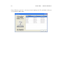
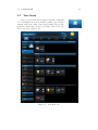
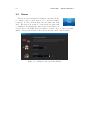
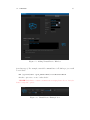
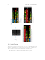
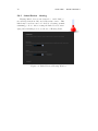
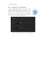
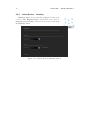
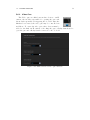
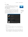
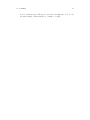
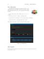
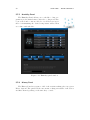
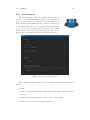
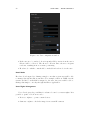
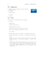
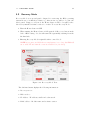
Advanced User’s Guide
8.VIII.2012 ver. 1.02\beta
Chapter 5
Home Center 2
The Home Center 2 is an electronic device which manages the Fibaro System.
The HC2 communicates with the system components (sensors, Fibaro modules)
located in user’s house using wireless radio communication. The Home Center
2 contains certified Z-Wave communication module allowing for support of up
to 230 devices, integrated within a Mesh network. The Home Center 2 uses a
simple, user friendly interface for the Fibaro system. The device enables it’s user
to manage and control the house using any mobile or stationery device, with
internet access, from anywhere in the world.
5.1
HC2 Finder
In a typical configuration, the Home Center 2 should be connected directly to a
router. This way the DHCP server will set the HC2 a dedicated dynamic IP. For
the greatest ease of use we have provided designated software, the Home Center
Finder, so that the user can find his/her HC2 IP within the local network. Home
59
60
CHAPTER 5. HOME CENTER 2
Center Finder scans the local network and displays the IP and MAC addresses
of all available HC2 units.
61
5.2. YOUR HOUSE
5.2
Your House
Your house tab is the Home Center 2 interface main window. It displays all devices available within a given Fibaro
System, such as modules, sensors and virtual devices. Elements are divided into groups, depending on the device type
and location in certain room.
Figure 5.1: Your Home tab
62
5.3
CHAPTER 5. HOME CENTER 2
Rooms
The Rooms tab is designed for adding rooms and sections,
i.e. single rooms, room groups, floors, or any user-defined
locations. To add a section, first enter it’s name and click
Add. The new section will be created and it’s name will
be displayed on left-hand list. After a new section has been
created, new room within the section may be created. To do so, the room name
must be entered, the desired section chosen, and the ”Add” button clicked.
Figure 5.2: Adding Rooms / Sections Window
63
5.4. DEVICES
5.4
5.4.1
Devices
Z-Wave Devices Inclusion
The Devices tab enables management of devices included
in the Fibaro System. Devices are Fibaro modules, Fibaro
system compatible sensors, IP cameras and virtual devices.
To add a Z-Wave device click Add. Once the system sets
itself into learning mode, Perform the tasks described in the
manuals (see chapters 3 and 4).
Figure 5.3: Adding Devices Window
5.4.2
IP Camera Inclusion
To add new IP camera, click Add. A new window will pop up, in which all
camera configuration options will be available. After completing the camera
configuration, click Save on the top of the screen.
When including new IP camera, following options need to be configured:
• Camera name
• Room in which the camera will be presented in the interface
• Camera model - May be picked from the list
• Camera access - User’s login and password
• IP Address of the camera
64
CHAPTER 5. HOME CENTER 2
Figure 5.4: Adding IP Camera window
• JPG path - JPG picture is used in remote access. All the necessary information should be available in the camera’s user manual
• MJPG path - MJPG stream path is used in local access.
• If the camera can be rotated - paths for each movement direction (specified
in camera’s user manual)
5.4.3
Creating Virtual Devices
Virtual devices were designed to control complicated devices such as boilers, air
conditioning units and home appliances (kitchen, audio and video appliances).
These kinds of devices may be managed through multiple component communication protocol, and the use of RS232 and Ethernet ports. The Fibaro System
makes it possible to create new device types and create designated communication
protocols.
Managing virtual devices is performed with TCP/IP protocols - Target IP
and TCP communication ports must be defined.
Next, the user defines a designated button, and defines the communication
to be sent after the button is used. The system supports string communicates
65
5.4. DEVICES
Figure 5.5: Adding Virtual Device Window
(text data type). For example, turn ON command line for Toshiba projector will
be as follows:
GET /cgi-bin/webrc.cgi?P_ON=OK HTTP/1.10x0D0x0A0x0D0x0A
Another option is to create ”value slider”.
*NOTE If the device confirm communication receipt please choose ”wait for
device’s response” option
Figure 5.6: Virtual Device Example Icon
66
5.4.4
CHAPTER 5. HOME CENTER 2
Deleting Devices
To delete device, simply click Delete. Device may be successfully deleted after
the HC2 enters the learning mode (please refer to Chapters 3 and 4).
Figure 5.7: Deleting Device Window
5.5
Scenes
TheScenes tab lets the user program complicated functions between multiple devices included in the system. Scenes
may be initiated by weather condition, a series of intuitive
timers or various sensor/module state.
A Scene is a group of commands sent to user defined
group of devices, e.g. ”open the blinds 50%; and set the lights to 30% brightness”.
Scenes may be triggered by clicking the ”Run scene” button. Scene may be also
triggered by user defined actions, e.g. ”run the scene if the motion sensor is
tripped or the room temperature exceeds 27 degrees”. Another option is to
define the scene triggering timers, e.g. ”run the scene each day at 8:30, and on
Monday at 12:15”.
To open a new scene window click Add. The new scene must me named and
assigned to certain room for easier configuration. After general parameters have
been set, The Scene ”Advanced” tab should be opened. This is the tab in which
the scene actions are programmed.
67
5.5. SCENES
Figure 5.8: New Scene Creation Window
5.5.1
Example Scenes
68
CHAPTER 5. HOME CENTER 2
5.6
Linked Devices
Linked Devices combine several devices into one device. Using this function will
result in controlling the group of related devices as if they were one single device.
The group will be presented in the HC2 interface as a single device.
The Home Center 2 offers four different Linked Devices panels:
5.6. LINKED DEVICES
• Heating
• Air Conditioning
• Humidity
• Video gate
69
70
5.6.1
CHAPTER 5. HOME CENTER 2
Linked Devices - Heating
Heating linked devices was designed to enable link between Relay Switch module and temperature sensor. This
linked may be used in control of boilers, floor heating, jacuzzis,
swimming pools etc. After creating the linked devices, managing and scheduling is done by the use of Heating Panel.
Figure 5.9: Linked Devices Heating Window
5.6. LINKED DEVICES
5.6.2
Linked Devices - Air Conditioning
Air conditioning linked devices are based on the same
principle as Heating Linked Devices. It is possible to add
multiple switches turning several air conditioning devices ON
/ OFF, so that air conditioning in multiple rooms or sections
may be operated as a single device. After air conditioning
liked devices has been created, managing and scheduling is
done by the use of the Air Conditioning panel.
Figure 5.10: Linked Devices Air Conditioning Window
71
72
5.6.3
CHAPTER 5. HOME CENTER 2
Linked Devices - Humidity
Humidity linked devices uses the principle described in
5.6.1/2. After Humidity linked devices have been created,
managing and scheduling of the new devices is done through
the Humidity Panel.
Figure 5.11: Linked Devices humidity window
5.6. LINKED DEVICES
5.6.4
73
Video Gate
The Video gate is a link between three devices - an IP
camera, the module responsible for opening the gate and
the module responsible for triggering the doorbell. After the
link has been created, the video gate may be controlled via
an iPhone. To create the video gate, three devices must be
added to the link: an IP camera overlooking the gate, a Relay Switch used to
open the gate and a Relay Switch connected to the doorbell.
Figure 5.12: Linked Devices Video-gate Window
74
CHAPTER 5. HOME CENTER 2
5.7
Panels
Panels simplify managing groups of related devices serving the same functionality, such as heating, air conditioning,
or watering the garden. Using Panels, you can easily program the devices’ schedule for the entire week.
5.7.1
SMS Panel
SMS Home Management is available in selected countries
and allows you to stay in control of your home even when
you don’t have a viable internet connection. SMS Panel lets
you define SMS communications sent by the system, define
the list of telephone numbers allowed to manage the house
and top-up the return messages account, used for the confirmation messages sent from sensors etc.
Figure 5.13: SMS Panel window
Example messages:
• HC2-000417.lights.livingroom.on -turns on all the lights in livingroom.
• HC2-000417.lights.livingroom.off - turns off all the lights in livingroom.
• HC2-000417.lights.house.status - sends the message informing of the
status of all devices named ”light” in the house. If, for example in the
living room any light is on, an excerpt from the return message will appear
as follows: livingroom: on. If all of the lights in the room are off, excerpt
5.7. PANELS
75
from a return message will appear as follows: livingroom: off. To use
the functionality, return messages pool must be bought.
76
CHAPTER 5. HOME CENTER 2
5.7.2
Alarm Panel
The Alarm Panel is designed to manage the alarm control
unit, integrated into the Fibaro System. The alarm central
unit is integrated with the use of two Relay Switch 2x1,5kW
modules.
In the Alarm Panel, the following devices need to be
present:
• Controlling Module - arming / disarming alarm
• Status Module - informing about zone status (armed / disarmed)
• Alarming Module - indicating armed zone breach
The defined alarm will be presented in the Your House menu.
Figure 5.14: Alarm Panel
Alarm Integration
For integrating the alarm system into Fibaro System, two Relay Switch 2x1,5kw
modules may be used.
5.7. PANELS
77
• Connect Arming/Disarming input of the alarm control unit to O1 and O2
of the first Relay Switch 2x1,5kW
• Connect Status, i.e. Armed / Disarmed output of the alarm control unit
to S1 and S2 inputs of the first Relay Switch 2x1,5kW
• connect alarming input of the alarm control unit (Breach / No Breach) to
outputs O1 and O2 of the second Relay Switch 2x1,5kW
78
5.7.3
CHAPTER 5. HOME CENTER 2
Heating Panel
The Heating Panel allows you to schedule heating programs at predetermined times. After the heating zones have
been created and rooms are added to it, all devices responsible for maintaining the desired temperature will work in
accordance with schedule.
Figure 5.15: Heating panel window
79
5.7. PANELS
5.7.4
Heating Panel
The Cooling Panel allows you to schedule cooling programs at predetermined times. After the cooling zones have
been created and rooms are added to it, all devices responsible for maintaining the desired temperature will work in
accordance with schedule.
Figure 5.16: Air Conditioning panel window
80
5.7.5
CHAPTER 5. HOME CENTER 2
Humidity Panel
The Humidity Panel allows you to schedule cooling programs at predetermined times. After the cooling zones have
been created and rooms are added to it, all devices responsible for maintaining the desired temperature will work in
accordance with schedule.
Figure 5.17: Humidity panel window
5.7.6
History Panel
The History Panel is a register of all of the activities taking place in a given
Fibaro System. The panel lets the user monitor changes in status of all devices
and filter them depending on the time they occured.
81
5.7. PANELS
5.7.7
Access Control
The Users Panel is configured to manage the accounts of
the users of a certain HC2 unit. It allows you to grant/block
access to the devices, e.g. cameras; scenes and system settings. From the Users Panel it is also possible to grant/block
access using the hotel mode for a given mobile application,
or set a perion for reporting GPS locations from a certain
iPhone device. Also, the Users Panel gives an option to define mobile devices which will receive Push Notifications.
Figure 5.18: Access Control Panel
After clicking the user’s name, the Users Panel shows the window shown in
fig 5.19.
• Login
• Password (at least 4 characters. The system will ask for password confirmation)
• E-mail address (all notifications will be sent to this e-mail)
• If the user is receive the notification massages
82
CHAPTER 5. HOME CENTER 2
Figure 5.19: User configuration window
• If the user is to be tracked - how frequently GPS position from the user’s
iPhone will be collected. The shorter collection time, the more frequent
readouts, resulting in more accurate positioning.
• Hotel mode - which rooms should be included in hotel mode for the user
Hotel Mode
Hotel mode is designed for defining a single room, that a given user will be able
to manage through the iPhone interface. For example, if there is USER 1 in the
system, and the room ROOM 1 assigned to the user, the person will be able to
manage this single room only through his iPhone application.
Users Rights Management
.
Users Panel gives the possibility for advanced control over users rights. It is
possible to grant or block an access to:
• Devices - rights to operate certain devices
• Cameras - rights to check the image from certain IP cameras
5.7. PANELS
83
• Scenes - rights to use certain scenes
• System - rights to manage certain system sections
List of iOS devices
This enables you to determine which of the users using iOs applications are to
receive Push notifications. If the user is allowed to remotely access to the system,
his iPhone must be marked on the list.
84
5.7.8
CHAPTER 5. HOME CENTER 2
Notifications Panel
Notifications panel gives the ability to create messages to
be used for informing the user of certain events taking place
in the house.
Figure 5.20: Notification Panel
85
5.7. PANELS
5.7.9
Localization Panel
Localization Panel uses user defined GPS points to activate GPS scenes. There are two ways of defining GPS
points - choosing on a map, or entering certain GPS coordinates. Each user may enter indefinite number of GPS
points.
Figure 5.21: Localization Panel
Usage example: USER 1 defines two GPS points HOME and WORK. Now
it is possible to create scene turning OFF all the lights in the house once the user
leaves the HOME location, and arms the alarm at home once the user enters
WORK location.
86
CHAPTER 5. HOME CENTER 2
5.8
Configuration
The Home Center 2 configuration options are divided into
the following categories:
• General
• LAN settings
• Location
• Backup
5.8.1
General
Basic information about the Home Center 2, including:
• Serial no.
• MAC address
• Current software version
• Z-Wave chip software version
• Time and date last software update was performed
• Time and date last system backup file was created
• Server status
General information window also allows for performing following actions:
• Restart - Home Center 2 soft restart, i.e. system shut down and started
again
• Z-Wave network reset - All of the system devices will be removed from HC2
Z-Wave chip memory, i.e. all of the device will have to be re-added to the
system
• Default settings - Home Center 2 memory is reset to factory state, i.e. all
of the devices are deleted together with their settings and dependencies
(scenes). HC2 software is downgraded to it’s oldest available version. After resetting to defaults, the HC2 software needs to be upgraded to latest
available version.
5.8. CONFIGURATION
Figure 5.22: Configuration Panel - General
5.8.2
LAN Settings
There are two basic options available: DHCP or Static IP.
Following parameters may be defined:
• Home Center 2 IP address
• Subnet mask
• Default gateway IP, used by HC2 to connect the web
• DNS server address
• Remote access enabling
Figure 5.23: Configuration Panel - LAN settings
87
88
CHAPTER 5. HOME CENTER 2
Important information on LAN settings
By default, the HC2 expects to be connected to a DHCP server. In this mode,
HC2 IP address may be obtained with the use of the HC2 Finder (see HC2
Finder ). Another option is to set Static IP. Static IP may be set from the LAN
settings tab, or manually, by holding the Recovery button (back side of the HC2
casing) after the device has been connected to power supply. In this case, the
HC2 will have following settings:
• IP Address: 192.168.81.1
• Subnet Mask: 255.255.255.0
• Gateway address: 192.168.81.1
When static IP has been set, it is possible to connect HC2 directly to Ethernet
port of a PC, however PC network settings must be set to match those of HC2:
• PC/MAC IP: 192.168.81.5
• Subnet mask:: 255.255.255.0
• Gateway address: 192.168.81.1
NOTICE After setting a static IP for the HC2 by pressing and holding the
Recovery button, please enter LAN settings to change connection type to DHCP,
when the HC2 is connected to the PC.
5.8. CONFIGURATION
5.8.3
89
Location
Location settings include time zone location, within which HC2 is installed. Additionally, it is possible to enter the longitude and latitude used for monitoring
weather conditions (also used in scenes).
Figure 5.24: Configuration Panel - Location info
90
5.8.4
CHAPTER 5. HOME CENTER 2
Backup
In this section the list of created backup files is displayed. Backup file is a copy
of a file containing the information’s about all devices added to the system and
all of their settings, users individual settings and the HC2 operating system.
Retrieving data from backup file means going back to all of the systems settings
that had been saved.
Figure 5.25: Configuration Panel - Backup Creation Window
5.9. RECOVERY MODE
5.9
91
Recovery Mode
Recovery Mode is a special panel, designed for retrieving the HC2 operating
system in case of technical problems, e.g. when it is not possible to log into the
user’s panel. Using recovery mode the Home Center 2 will be brought back to
the factory installed software version, i.e. 1.009. To access Recovery mode:
1. Turn the Home Center 2 OFF
2. When turning the Home Center 2 ON again, hold Recovery button in the
back of HC2 casing - diodes will turn ON sequentially, starting from the
left hand side
3. Entering Recovery Mode is signaled with a control diode
NOTE! if you press and hold the recovery button for too long, the HC2 will
set to static IP and network connection will be lost (see 5.8.2)
Figure 5.26: Recovery Mode View
The left hand menu displays the following information:
• Recovery version
• HC2 serial no
• IP Address - IP address, visible in local network
• MAC address - Module name and software version
92
CHAPTER 5. HOME CENTER 2
Figure 5.27: Recovery Mode - retrieving from backup
• Last backup - The date and time when last backup file was created
• Devices - The Number of devices saved in last backup file
• Rooms - The Number of rooms saved in last backup
• Scenes - The Number of scenes saved in last backup file
• Online - The HC2 internet access