1
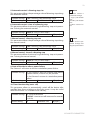
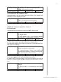
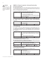
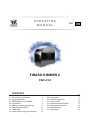
O P E R AT I N G
MANUAL
ENG
FIBARO DIMMER 2
FGD-212
CONTENTS
#1: Description and features
#2: Supported loads
#3: FIBARO Bypass 2 (FGB-002)
#4: Installation
#5: Adding/removing the device
#6: Operating the device
#7: Calibration
#8: Power and energy consumption
v1.0
4
5
7
8
11
12
15
16
#9: Associations
#10: Z-Wave range test
#11: Error modes
#12: Additional functionality
#13: Advanced parameters
#14: Specifications
#15: Guarantee
17
18
19
21
22
32
33
3
Important safety information
!
Read this manual before attempting to install the device!
Failure to observe recommendations included in this manual
may be dangerous or cause a violation of the law. The manufacturer,
Fibar Group S.A. will not be held responsible for any loss or damage
resulting from not following the instructions of operating manual.
Danger of electrocution!
Dimmer 2 is designed to operate in electrical home installation. Faulty connection or use may result in fire or electric shock.
All works on the device may be performed only by a qualified and
licensed electrician. Observe national regulations.
Even when the device is turned off, voltage may be present at its terminals. Any maintenance introducing changes into the configuration
of connections or the load must be always performed with disabled
fuse
!
Required overcurrent protection
Dimmer 2 must be protected with an overcurrent protection
(fuse) with a value not higher than 10A.
General information about
the FIBARO System
FIBARO is a wireless smart home automation system, based on the
Z-Wave protocol. All of available devices can be controlled through
a computer (PC or Mac), smartphone or tablet. Devices are not only
receivers, but can also repeat the signal, increasing the Z-Wave
network’s range. It gives advantage over traditional wireless systems
that require direct link between transmitter and receiver, as a result the
construction of the building could affect network’s range negatively.
Every FIBARO network has its unique identification number (home
ID). Multiple independent networks can exist in the building without
interfering. Transmission security of FIBARO System is comparable to
wired systems.
Z-Wave technology is the leading solution in smart home automation.
There is a wide range of Z-Wave devices that are mutually
compatible, independently of manufacturer. It gives the system the
ability to evolve and expand over time. For more information visit:
www.fibaro.com.

4
#1: Description and features
Remotely controlled light dimming module is designed to work with
various types of light sources. It may be connected to two-wire or
three-wire configuration so it can operate with or without neutral
lead. FIBARO Dimmer 2 can switch or dim connected light source
either through radio waves or through the wall switch connected
directly to it.
New FIBARO Dimmer 2 is equipped with an algorithm of smart light
source detection which makes configuration easier and ensures high
compatibility of the device. It may be used as a switch with nondimmable light sources (in 3-wire connection).
i
NOTE
This device may be
used with all devices
certified with Z-Wave
certificate and should
be compatible with
such devices produced by other manufacturers.
Main features of FIBARO Dimmer 2:
•
Compatible with any Z-Wave or Z-Wave+ Controller
•
Controlled by FIBARO Home Center or any other Z-Wave controller
•
Advanced microprocessor control
•
Implemented algorithm of smart light source detection
•
Auto-adjustment of the appropriate control mode to connected
load
•
Active power and energy metering functionality
•
Soft start function
•
Memory of the last lighting level settings
•
Works with various types of switches – momentary, toggle,
three-way, etc.
•
Active element: semiconductor electronic switch
•
To be installed in wall switch boxes of dimensions allowing for
installation, conforming to provisions of applicable regulations
•
FGD-212 is an extension unit
FIBARO Dimmer 2 is a fully
compatible Z-Wave PLUS device.
Description and features
5
#2: Supported loads
As a dimmer it operates under the following loads:
•
230V operated conventional incandescent and halogen light
sources
•
12V operated ELV halogen lamps and dimmable LED bulbs (with
electronic transformers)
•
12V operated
transformers)
•
dimmable LED bulbs
•
dimmable compact fluorescent CFL tube lamps
•
supported dimmable light sources (power factor > 0.5) with
minimal power of 5VA using FIBARO Bypass 2 (depending on the
type of load)
MLV
halogen
lamps
(with
ferromagnetic
!
CAUTION
FIBARO Dimmer 2
supports only compact fluorescent tube
lamps and fluorescent
tube lamps with electronic ballast. Do not
connect other types
of fluorescent lamps!
i
NOTE
You will find more
about FIBARO Bypass
2 in chapter #3 on
page 7.
Without dimming function it may work with:
•
compact fluorescent CFL tube lamps with electronic ballast
•
fluorescent tube lamps with electronic ballast
•
LED bulbs (power factor > 0.7)
•
supported light sources (power factor > 0.5) with minimal power
of 5VA using FIBARO Bypass 2 (depending on the type of load)
!
Applied load and the Dimmer 2 itself may be damaged if
the applied load is inconsistent with the technical specifications!
When connecting FIBARO Dimmer 2 act in accordance with the
following rules:
•
Do not connect loads greater or less than those recommended
•
Do not connect different types of light sources simultaneously
•
Do not connect the power supply without a load
•
Do not connect more than one transformer with Dimmer 2 output
•
When using magnetic transformer load it with 50% of its nominal
power at minimum
•
Minimize number of electronic transformers in a circuit, noises
caused by them in electrical grids may affect Dimmer’s operation
Supported loads
6
i
NOTE
Some types of the LED
bulbs and compact
fluorescent lamps are
designed to work in
leading edge operating mode.
FIBARO Dimmer 2 uses different operating modes to control following types of loads:
1. „Trailing edge” for resistive loads (R)
2. „Trailing edge” for resistive-capacitive loads (RC)
3. „Leading edge” for resistive-inductive loads (RL)
Recommended values of power for supported loads:
Supported load types
220-240V~
Resistive loads
Supported loads
Conventional incandescent
and halogen light sources
Resistive-capacitive loads
50-250W
Fluorescent tube lamp (compact / with electronic ballast),
electronic transformer, LED
Resistive-inductive loads
50-200VA
Ferromagnetic transformers
50-220VA
7
#3: FIBARO Bypass 2 (FGB-002)
FIBARO Bypass 2 (FGB-002) is a device designed to work with FIBARO
Dimmer 2 (FGD-212). It should be used in case of connecting LED
bulbs or energy saving compact fluorescent lamps. FIBARO Bypass 2
prevents flickering of the LED lights and glowing of the turned off
compact fluorescent lamps.
In the case of 2-wire connection, FIBARO Bypass 2 allows to reduce
minimum power of load required by the Dimmer 2 for correct
operation. FGB-002 provides powering of the Dimmer 2 in case
of controlling the low loads of minimum power down to 5VA (for
cosφ>0.5).
!
CAUTION
Dimmer 2 was designed to work only
with FGB-002. Connecting other devices
may cause damage to
the Dimmer 2.
!
CAUTION
In the case of 2-wire
connection do not
connect load below
minimal power without FGB-002.
Device installation:
1. Switch off the mains voltage (disable the fuse)
2. Connect the Bypass 2 in accordance with „Installation” on page 8
3. Follow the Dimmer 2 installation
4. Force the calibration procedure with FIBARO Bypass 2 using
RED menu position (see „Operating the device” on page 12) or
through setting parameter 13 to 2 (see „Advanced parameters” on
page 22)
Specifications:
Power supply:
100-240 V~ 50/60 Hz
Operational temperature:
0-35°C
Dimensions (L x W x H):
31 x 21,6 x 13 mm
Power consumption:
< 1,4 W
!
CAUTION
Bypass 2 works only
with Dimmer 2 in trailing edge mode. Do
not connect the Bypass to the Dimmer
operating in leading
edge mode.
!
CAUTION
Bypass 2 is sensitive
to the frequent changes of the state of
Dimmer 2 (alternate
switching on and off ).
Significant changes in
brightness should not
be performed more
than once per second.
FIBARO Bypass 2 (FGB-002)
8
#4: Installation
Connecting the FIBARO Dimmer 2 in a manner inconsistent
with manual may cause risk to health, life or material
damage.
!
When connecting FIBARO Dimmer 2 act in accordance with the
following rules:
•
Connect only in accordance with one of the diagrams
•
Electrical installation must be protected by overcurrent protection
(fuse) of with a value not higher than 10A
•
Dimmer 2 should be installed in a wall switch box compliant with a
relevant national safety standards and with depth no less than 60mm
•
Electrical switches used in installation should be compliant with the
relevant safety standards
•
Length of wires used to connect the control switch should not
exceed 20m
Notes for the diagrams:
L - terminal for live lead
S1 - terminal for switch no. 1 (has the option of
entering the device in learning mode)
DIMMER
B
S2 - terminal for switch no. 2
Sx - terminal for power supply to the switch connected to the Dimmer 2
N - terminal for neutral lead
- output terminal of the Dimmer 2 (controlling
connected light source)
B - service button (used to add/remove the device
and navigate the menu)
Installation of the FIBARO Dimmer 2:
1. Switch off the mains voltage (disable the fuse)
2. Open the wall switch box
3. Connect with one of following the diagrams:
Installation
9
l
n
single switch
double switch
l
n
DIMMER
i
DIMMER
B
B
Wiring diagram no. 1 - 2-wire connection
l
n
single switch
double switch
l
n
DIMMER
NOTE
Switch connected to
the S1 terminal is a
master switch. It activates the basic functionality of the Dimmer 2 (turning the
light on/off, dimming)
and starts the learning
mode (Add/Remove).
The switch connected
to the S2 terminal is an
optional switch and
pushing it without
changing the configuration parameters will
not affect the status of
the device. Functionality of the switches
can be reversed by
adjusting advanced
parameter (see „Advanced parameters”
on page 22).
DIMMER
B
B
Wiring diagram no. 2 - 3-wire connection
2-wire connection
l
n
l
n
3-wire connection
BYPASS
DIMMER
B
BYPASS
DIMMER
B
Wiring diagram no. 3 - connecting FGB-002
Installation
DIMMER
i
NOTE
It is not recommended to install different
types of wall switches
(momentary, toggle,
etc.) in a 3-way connection.
1
P
3
13
1
P2
P
B
10
3
DIMMER
B
Wiring diagram no. 4 - 3-way switch connection
Wiring diagram no. 5 - momentary wall switches
connection
i
NOTE
After switching on the
mains voltage LED
indicator will signal
Z-Wave network inclusion state with a
colour:
GREEN - device added
RED - device not added
RED/GREEN ALTERNATELY- Z-Wave error
4. After verifying correctness of connection switch on the mains
voltage
5. Wait around 30s for the calibration process to end (see „Calibration” on page 15), light may blink during the process
6. After successful calibration the device will be turned off by default
7. Add the device to the Z-Wave network (see „Adding/removing the
device” on page 11)
8. Turn off the mains voltage, then arrange the device and its antenna in a wall switch box
9. Close the wall switch box and turn on the mains voltage
Tips for arranging the antenna:
Installation
•
Locate the antenna as far from metal elements as possible
(connecting wires, bracket rings, etc.) in order to prevent
interferences.
•
Metal surfaces in the direct vicinity of the antenna (e.g. flush
mounted metal boxes, metal door frames) may impair signal
reception!
•
Do not cut or shorten the antenna - its length is perfectly matched
to the band in which the system operates.
11
#5: Adding/removing the device
Adding (Inclusion) - Z-Wave device learning mode, allowing to add
the device to existing Z-Wave network.
To add the device to the Z-Wave network:
1. Place the Dimmer 2 within the direct range of your Z-Wave
controller
2. Identify switch no. 1 (turns the light on) or the B-button (located
on the device’s housing)
3. Set the main controller in (security/non-security) add mode (see
the controller’s manual)
4. Quickly, three times press switch no. 1 or the B-button
5. Wait for the adding process to end
6. Successful adding will be confirmed by the Z-Wave controller’s
message
Removing (Exclusion) - Z-Wave device learning mode, allowing to
remove the device from existing Z-Wave network.
To remove the device from the Z-Wave network:
1. Place the Dimmer 2 within the direct range of your Z-Wave
controller
2. Identify switch no. 1 (turns the light on) or the B-button (located
on the device’s housing)
3. Set the main controller in remove mode (see the controller’s
manual)
4. Quickly, three times press switch no. 1 or the B-button
5. Wait for the removing process to end
6. Successful removing will be confirmed by the Z-Wave controller’s
message
7. Dimmer 2 will start the calibration process (see „Calibration” on
page 15)
i
NOTE
For toggle switches in
default configuration
perform six position
changes.
i
NOTE
In case of problems
related to unknown
configuration or type
of external switch use
the B-button to add/
remove.
!
CAUTION
While adding the
Dimmer 2 to the
network
with
connected
toggle
switch, ensure that
all switch contact is
open (off ). Otherwise
it will prevent adding/
removing the device
to/from the network.
i
NOTE
Removing the Dimmer 2
from the Z-Wave network restores all the
default parameters of
the device, but does
not reset power metering data.
i
NOTE
Adding/removing is
not possible during the
calibration procedure.
i
NOTE
Adding in security
mode must be performed up to 2 meters
from the controller.
Adding/removing the device
12
#6: Operating the device
Controlling the Dimmer 2 using a switch:
Momentary switch (after releasing the switch a spring automatically
pushes back and disconnects the switch):
•
Turning the light ON/OFF: change the position of switch n
o. 1. The
Dimmer 2 will be activated always at previously set brightness
level.
•
Brightening/dimming the light: hold switch no. 1 down. When the
switch is held down, the Dimmer 2 will always reach the extreme
value of 1% or 99%.
•
Turning the light ON completely: fast double-click switch n
o. 1.
The Dimmer 2 will set the load at 99%.
Toggle switch (operates as a two-position switch, it has no spring
that would set one position of the switch):
•
Turning the light ON/OFF: toggle switch no. 1. The Dimmer 2 will
be activated always at previously set brightness level.
•
Turning the light ON completely: toggle twice switch no. 1. The
Dimmer 2 will set the load at 99%.
Controlling the Dimmer 2 using FIBARO Home Center controller:
After adding the Dimmer 2 to the network, it will be represented in
the FIBARO Home Center controller by the following icon:
Dimming/brightening is performed by moving the slider. The current
status of the Dimmer 2 is shown on the bar indicator.
Turning the device ON/OFF – ON and OFF icons are used for setting
the last saved state or turning off the Dimmer 2.
Operating the device
13
Controlling the Dimmer 2 using a command: ALL ON/ALL OFF in
non-secure mode:
The Dimmer 2 responds to commands ALL ON/ALL OFF that may be
sent by the Z-Wave controller. ALL ON/ALL OFF commands are usually
implemented in the remote controllers using Z-wave protocol, and
they are used to issue commands directed to the entire system.
By default, both commands ALL ON and ALL OFF are accepted. Settings may be changed by modifying the value of parameter 11 (see
„Advanced parameters” on page 22). In this way the user may determine to which commands the device should respond.
Resetting the Dimmer 2:
1. Disconnect the power supply
2. Remove the Dimmer 2 from the wall switch box
3. Connect the power supply
4. Locate the B-button on the housing
5. Press and hold the B-button to enter the menu mode
6. Wait for the visual LED indicator to turn yellow
7. Quickly release and click the B-button again
8. After few seconds the device will be restarted, which is signalled
with the red LED indicator colour
9. The device enters the calibration mode
i
NOTE
Resetting the device is
not the recommended way of removing
the device from the
Z-Wave network. Use
reset procedure only
if the primary controller is missing or
inoperable.
Certain
device removal can be
achieved by the procedure of removing
described in „Adding/
removing the device”
on page 11.
Controlling the Dimmer 2 using the B-button:
FIBARO Dimmer 2 is equipped with a B-button, which allows to use
the MENU mode and additionally perform the following actions:
1x click:
•
alarm mode cancellation (flashing alarm)
•
exit the error mode
•
select the desired MENU option (if MENU mode is active)
3x click:
•
send the Node Info Z-Wave command frame (adding/removing)
Holding:
•
enter the MENU mode (confirmed by the LED indicator)
Operating the device
14
MENU mode & visual indications:
FIBARO Dimmer 2 has a MENU with each position indicated by the
specified LED indicator colour. In order to enter the menu press the
B-button and hold for at least 2 seconds. While the B-button is still
pressed, LED indicator colour will change in the following sequence:
BLUE - initiate the load calibration procedure (see „Calibration” on
page 15)
RED - load calibration procedure with FIBARO Bypass 2 (see „Calibration” on page 15)
WHITE - activate turning the load on/off using the B-button
GREEN - reset the energy consumption data memory (see „Power and
energy consumption measurement” on page 16)
VIOLET - initiate the Z-Wave network range test (see „Z-Wave range
test” on page 18)
YELLOW - reset the FIBARO Dimmer 2 to factory defaults
Release the B-button to choose the desired function and confirm your
choice with the B-button click.
Operating the device
15
#7: Calibration
Dimmer 2 is equipped with an algorithm of smart light source detection. Depending on the connected type of light source, it automatically adjusts an optimal control mode (leading edge for inductive
loads, trailing edge for capacitive or resistive loads). The procedure of
learning the light source type is called calibration.
Calibration automatically adjusts maximum and minimum light levels
(parameter 1 and 2). However, the installer is obliged to verify the
proper operation of the device, according to control modes description. There is a 10% probability that calibration settings will require a
manual correction. In a 2-wire connection for loads other than resistive parameter 1 settings must be adjusted manually.
Calibration procedure is performed always after removing the device
from the Z-Wave network. If the device is not included, after each
power on/off calibration will occur. For the included device, calibration is performed in accordance with the parameter 35 settings.
Calibration may be forced:
•
by setting parameter 13 to 1 or 2 (with/without FIBARO Bypass 2)
•
through triple clicking and holding the main light switch (each
hold for more than 5 seconds)
•
by selecting the appropriate MENU option using the B-button
(see „Operating the device” on page 12).
By default, calibration is performed without FIBARO Bypass 2. In case
of connecting the Bypass 2, it is required to force the appropriate
calibration procedure using B-button menu or through parameter
13. The device saves the last calibration enforcement mode (with or
without Bypass 2).
The result of calibration will be confirmed with the LED indicator
glowing in one of the following colours:
GREEN - Light source recognized as dimmable, dimming levels set,
brightness may be controlled using the S1 switch.
YELLOW - Light source recognized as non-dimmable, possibility to
turn ON/OFF connected light with default parameters settings.
RED - Calibration procedure failed. Possible reasons: lack of connected load or connected light source exceeds maximum power, which
may be controlled by the Dimmer 2.
BLINKING RED - Calibration procedure failed. Possible reasons: installation failure or damaged load (causing activation of the overcurrent protection).
!
CAUTION
Some types of LED
and CF lamps are designed to operate in
leading edge mode
(with
conventional
dimmers). Information
about proper operation mode of the bulb
should be included in
its manual. In this case
you have to manually
force the desired operating mode using
parameter 30.
!
CAUTION
After changing the
load launch the calibration or remove and
add the device. Before
changing the operating mode or performing the calibration procedure the light must
be turned off. Verify
the operating mode,
according to product
documentation.
!
CAUTION
During the calibration
procedure, radio connection is disabled and
the Dimmer 2 does not
respond to any commands. It may cause
temporary problems
with communication
in the Z-Wave network.
After completing the
calibration, communication with the module will be restored.
Calibration
16
#8: Power and energy
consumption
!
CAUTION
FIBARO Dimmer 2 in
the 3-wire connection
has the power and
energy measurement
function. In case of the
2-wire connection this
function is available
only for load of cosφ
≥ 0.99. In other cases
power is estimated
and can differ from actual power consumed
by the device.
FIBARO Dimmer 2 allows for the active power and energy consumption monitoring. Data is sent to the main Z-Wave controller, e.g. Home
Center. Measuring is carried out by the most advanced micro-controller technology, assuring maximum accuracy and precision.
Electric active power - power that energy receiver is changing into a
work or a heat. The unit of active power is Watt [W].
Electric energy - energy consumed by a device through a time
period. Consumers of electricity in households are billed by suppliers on the basis of active power used in given unit of time. Most
commonly measured in kilowatt-hour [kWh]. One kilowatt-hour is
equal to one kilowatt of power consumed over period of one hour,
1kWh = 1000Wh.
Resetting consumption memory:
!
CAUTION
FIBARO Dimmer 2
stores
periodically
(every 5 minutes) the
consumption
data
in the device memory.
Disconnecting
the module from the
power supply will not
erase the energy consumption data.
Dimmer 2 allows to erase stored consumption data in three ways:
a)By resetting the device (see „Operating the device” on page 12).
b)Using functionality of a Z-Wave controller (see the controller’smanual).
c)Manually clearing the data using the following procedure:
1. Make sure that the device is connected to the power supply
2. Press and hold the B-button for a few seconds, until LED indicator glows GREEN
3. Release the B-button.
4. Press the B-button briefly
5. Energy consumption memory has been erased
i
NOTE
Power measurement
in the 2-wire connection does not include
mains voltage fluctuations within +/- 10%.
* Measurements in this
case are only illustrative, returned values
may differ from the
actual measurement.
In the case of reporting incorrect values
change the values of
parameters 58 and 59.
Table of power measurement accuracy:
FGD-212
3-wire connection
2-wire connection
Brightness>70%
Brightness<70%
Brightness>70%
Brightness<70%
resistive load
+/- (0.5 %
+ 0.2W)
+/- (2 %
+ 0.2W)
+/- (2 %
+ 0.2W)
+/- (4 %
+ 0.2W)
resistiveinductive load
+/- (0.5 %
+ 0.2W)
+/- (2 %
+ 0.2W)
Power
Power
metering
metering
approximate* approximate*
resisitvecapacitive load
+/- (0.5 %
+ 0.2W)
+/- (2 %
+ 0.2W)
Power
Power
metering
metering
approximate* approximate*
Power and energy consumption
17
#9: Associations
Association (linking devices) - direct control of other devices within
the Z-Wave system network using the wall switch connected to the
Dimmer 2.
The association enables the Dimmer 2 to control directly a device
included in Z-Wave network e.g. other Dimmer, Relay Switch, Roller
Shutter or scene (may be controlled only through a Z-Wave controller).
The Dimmer 2 provides the association of five groups:
1st Association Group „Lifeline” reports state of the device. Main
Z-Wave+ network controller should be added to this group. The „Lifeline” group can handle only one device. It is not recommended to
modify this group.
2nd Association Group „On/Off (S1)” is assigned to switch no. 1.
Sends BASIC command class frame according to the state of the device.
3rd Association Group „Dimmer (S1)” is assigned to switch no. 1.
Sends MULTILEVEL SWITCH command class frame. Allows sending
dim/brighten command to associated devices.
4th Association Group „On/Off (S2)” is assigned to switch no. 2.
Sends BASIC command class frame according to the state of the device.
i
NOTE
Association ensures
direct transfer of
control
commands
between devices, is
performed
without
participation of the
main controller and
requires
associated
device to be in the direct range.
i
NOTE
Dimmer 2 supports
the operation of multichannel
devices.
Multichannel devices
are devices that include two or more circuits inside one physical unit.
5th Association Group „Dimmer (S2)” is assigned to switch no. 2.
Sends MULTILEVEL SWITCH command class frame. Allows sending
dim/brighten command to associated devices.
Dimmer 2 in 2nd to 5th group allows for controlling 5 regular and 5
multichannel devices per an association group, out of which 1 field is
reserved for the Z-Wave network main controller. It is not recommended to associate more than 10 devices in general, as the response time
to control commands depends on the number of associated devices.
In extreme cases, system response may be delayed.
To add an association (using the Home Center controller):
1. Go to device options by clicking the icon:
2. Select the „Advanced” tab
3. Specify to which group and what devices are to be associated
4. Wait for the configuration process to end. Sending relevant information to devices added to associated groups may take even a
few minutes
Associations
18
#10: Z-Wave range test
!
CAUTION
To make Z-Wave range
test possible, the device must be added
to the Z-Wave controller. Testing may stress
the network, so it is
recommended to perform the test only in
special cases.
FIBARO Dimmer 2 has a built in Z-Wave network main controller’s
range tester.
Follow the below instructions to test the main controller’s range:
1. Press and hold the B-button until the visual indicator glows violet
2. Release the B-button
3. Press the B-button again, briefly
4. Visual indicator will indicate the Z-Wave network’s range (range
signalling modes described below)
5. To exit Z-Wave range test, press the B-button briefly
i
NOTE
Communication mode
of the Dimmer 2 may
switch between direct
and one using routing, especially if the
device is on the limit
of the direct range.
Z-Wave range tester signalling modes:
Visual indicator pulsing green - Dimmer 2 attempts to establish a
direct communication with the main controller. If a direct communication attempt fails, the device will try to establish a routed communication, through other modules, which will be signalled by visual
indicator pulsing yellow.
Visual indicator glowing green - Dimmer 2 communicates with the
main controller directly.
Visual indicator pulsing yellow - Dimmer 2 tries to establish a routed communication with the main controller through other modules
(repeaters).
Visual indicator glowing yellow - Dimmer 2 communicates with
the main controller through the other modules. After 2 seconds the
device will retry to establish a direct communication with the main
controller, which will be signalled with visual indicator pulsing green.
Visual indicator pulsing violet - Dimmer 2 does communicate at the
maximum distance of the Z-Wave network. If connection proves successful it will be confirmed with a yellow glow. It’s not recommended
to use the device at the range limit.
Visual indicator glowing red - Dimmer 2 is not able to connect to
the main controller directly or through another Z-Wave network device (repeater).
Z-Wave range test
19
#11: Error modes
Description of error messages of the Dimmer 2
Events result from installation flaws, faulty light source operation or
incorrect manual changes in advanced configuration. The device may
stop responding to user’s commands and actions, leaving the light
source off. Message with information about the type of error is sent
by default (using Z-Wave network).
i
NOTE
Pressing any of the
connected switches or
changing state of the
device using the controller will exit error
mode.
Error messages:
A) OVERTEMPERATURE ERROR
Dimmer 2 features self-temperature measurement function. In case
of reaching critical temperature, the load is turned off and the gateway receives an information about exceeding maximum temperature
of the module.
B) LOAD ERROR
Dimmer 2 is equipped with functionality of detecting the burnt out
bulb. In case of such situation, Dimmer 2 sends the notification about
load failure. Described function is not available for values of parameter 58 different than 0.
Power variation is detected in accordance with the settings of parameters 15 and 16.
Example:
Parameter 15 set to 30%.
i
NOTE
If parameter 35 is set
to 3 or 4, the load will
be calibrated again after turning on the load
or an occurrence of
LOAD ERROR, SURGE
or OVERCURRENT error.
Parameter 16 set to 5 seconds.
Dimmer 2 will detect the change of load at the moment of power
variation by 30% compared to standard power consumption (measured during the calibration) and after 5 seconds from brightness level
stabilization.
This function is available only in a control mode compliant with the
mode recognized during the calibration (parameter 14 set to 1).
Appearing of an error may be the result of not connecting the load. It
may suggest burning out all of the loads connected to the Dimmer 2.
Damaged load should be immediately replaced. After connecting the
new load, FIBARO Dimmer 2 will return to normal operation.
C) SURGE ERROR
Appearing of an error may be the result of electrical surges, incorrect
load control (inductive load controlled in trailing edge mode) or connecting the prohibited type of load.
Error modes
20
D) OVERCURRENT ERROR
Appearing of an error may also be the result of rapid powering on
the load. It may also occur if the soft-start functionality is disabled
(parameter 34 set to 0) or as a result of the short circuit.
If parameter 37 is set to 1, the device will automatically try to turn on
again.
I f described error has been caused by the rapid powering on the load,
then FIBARO Dimmer 2 will return to normal operation after reenabling.
After three unsuccessful automatic tries of turning on the load, Dimmer 2 will stay in OVERCURRENT error mode (module turned off ). In
such situation, it is required to remove the failure (possible short circuit in the installation.) Otherwise, it is recommended to set the long
soft-start (parameter 34 set to 2).
E) OVERLOAD ERROR
Appearing of an error is a result of connecting receivers with too
much power consumption. In this case FIBARO Dimmer 2 will automatically turn off the lighting.
It is required to reduce power consumption of connected load (e.g. by
reducing the number of receivers) and turn on the light source again
by the wall switch or a Z-Wave command.
F) VOLTAGE DROP ERROR
Appearing of an error in a 2-wire connection may be the result of
mains voltage drop or a too high brightness level of the light source.
If parameter 37 is set to 1, the device will automatically try to turn on
again.
Voltage drop error suggests that parameter 2 value should be reduced until disappearing of the failure. You can also recalibrate the
load using parameter 13.
After three unsuccessful automatic tries of turning on the load, Dimmer 2 will stay in VOLTAGE DROP error mode (module turned off ).
G) HARDWARE FAIL ERROR
Appearing of an error may be a result of serious hardware failure of
the Dimmer 2. In this case the Dimmer 2 sets the maximum brightness
level and the LED visual indicator starts blinking in red. All external
actions (Z-Wave commands, pressing the switches, menu settings)
will be ignored.
We recommend disconnecting the device from the power supply
and contacting the customer service or to initiate the guarantee
procedure.
This error may also appear as a result of enabling the Dimmer 2
without load connected to the output in 3-wire connection. It is not a
dangerous situation. We recommend disabling the fuse, connecting
the load and enabling the fuse again.
Error modes
21
#12: Additional functionality
Software update
Dimmer 2 features remote software update (initiated by the main
controller). Update status is signalled by the LED indicator with cyan
colour:
• slow blinking - transferring data via Z-Wave and saving to the
flash memory
• fast blinking - copying data from the external memory to the
memory of the microcontroller
Operating alarm data frames
FIBARO System allows user to set response of devices to alarm situations (response to data-frames ALARM_REPORT and SENSOR_ALARM_
REPORT). Dimmer 2 responds to the following types of alarms:
•
General Purpose Alarm - GENERAL PURPOSE ALARM
•
Smoke Alarm - ALARM CO2, ALARM CO, ALARM SMOKE
•
Water Flooding Alarm - ALARM WATER
•
Temperature Alarm - ALARM HEAT
Alarm data-frames are sent by devices that are system sensors (e.g.,
flood sensors, smoke detectors, motion detectors, etc.).
The device may respond in the following manner to received data-frames (settings are configured in configuration parameters, see
„Advanced parameters” on page 22):
0 - DEACTIVATION - the device does not respond to alarm data frames
1 - DIMMER 2 ON - the device turns on after detecting an alarm
2 - DIMMER 2 OFF - the device turns off after detecting an alarm
3 - ALARM FLASHING - the device periodically changes its status to
the opposite when it detects an alarm (lights on/off alternately)
Additional functionality
22
#13: Advanced parameters
Dimmer 2 allows to customize its operation to user’s needs. The settings are available in the FIBARO interface as simple options that may
be chosen by selecting the appropriate box.
In order to configure FIBARO Dimmer 2 (using the Home Center controller):
1. Go to the device options by clicking the icon:
2. Select the „Advanced” tab
!
CAUTION
The maximum
brightness level (parameter 2) must be
greater than the minimum brightness level
(parameter 1).
99%
99%
GROUP 0 - The Dimmer 2 behavior - Basic functionalities
1. Minimum brightness level (parameter is set automatically during
the calibration process)
The parameter can be changed manually after the calibration.
Available settings: 1-98 - percentage level of brightness
Default setting:
1
Parameter size:
1 [byte]
2. Maximum brightness level (parameter is set automatically during
the calibration process)
max
The parameter can be changed manually after the calibration.
Available settings: 2-99 - percentage level of brightness
Default setting:
99
Parameter size:
1 [byte]
min
*
0%
1%
real scale
*
scale available
to the user
(virtual)
incandescence level
of dimmable
compact fluorescent lamps
3. Incandescence level of dimmable compact fluorescent lamps
Virtual value set as a percentage level between parameters MIN (1%)
and MAX. (99%). The Dimmer 2 will set to this value after first switch
on. It is required for warming up and switching dimmable compact
fluorescent lamps and certain types of light sources.
Available settings: 1-99 - percentage level of brightness
Default setting:
1
Parameter size:
1 [byte]
4. Incandescence time of dimmable compact fluorescent lamps
This parameter determines the time required for switching compact
fluorescent lamps and certain types of light sources. Setting this parameter to 0 will disable the incandescence functionality.
Available settings: 0-255 (0-25.5s)
Default setting:
0
Parameter size:
Advanced parameters
2 [bytes]
23
5. Automatic control - dimming step size
This parameter defines the percentage value of dimming step during
the automatic control.
Available settings: 1-99 - dimming step percentage value
Default setting:
1
Parameter size:
1 [byte]
6. Automatic control - time of a dimming step
This parameter defines the time of single dimming step set in parameter 5 during the automatic control.
Available settings: 0-255 (0-2.55s, in 10ms steps)
Default setting:
1 (10ms)
Parameter size:
i
NOTE
Automatic control is
performed through:
- single push-button
click
- double push-button
click
- Z-Wave control frames
2 [bytes]
7. Manual control - dimming step size
This parameter defines the percentage value of dimming step during
the manual control.
Available settings: 1-99 - dimming step percentage value
Default setting:
1
Parameter size:
1 [byte]
i
NOTE
Manual control is performed through holding the push-button.
8. Manual control - time of a dimming step
This parameter defines the time of single dimming step set in parameter 7 during the manual control.
Available settings: 0-255 (0-2.55s, in 10ms steps)
Default setting:
5 (50ms)
Parameter size:
2 [bytes]
9. State of the device after a power failure
The Dimmer 2 will return to the last state before power failure.
Available settings: 0 - the Dimmer 2 does not save the state before
a power failure, it returns to „off” position
Default setting:
1 - the Dimmer 2 restores its state before power
failure
1
Parameter size:
1 [byte]
10. Timer functionality (auto - off)
This parameter allows to automatically switch off the device after
specified time from switching on the light source. It may be useful
when the Dimmer 2 is installed in the stairway.
Available settings: 0 - Function disabled
Default setting:
1-32767 - time to turn off measured in seconds
(1s-9.1h)
0
Parameter size:
2 [bytes]
Advanced parameters
24
11. ALL ON/ALL OFF function
Parameter allows for activation/deactivation of Z-Wave commands
enabling/disabling all devices located in direct range of the main
controller.
Available settings: 0 - ALL ON not active, ALL OFF not active
1 - ALL ON not active, ALL OFF active
2 - ALL ON active, ALL OFF not active
Default setting:
255 - ALL ON active, ALL OFF active
255
Parameter size:
2 [bytes]
13. Force auto-calibration
Changing value of this parameter will force the calibration process.
During the calibration parameter is set to 1 or 2 and switched to 0
upon completion.
Available settings: 0 - readout
1 - force auto-calibration of the load without
FIBARO Bypass 2
Default setting:
2 - force auto-calibration of the load with
FIBARO Bypass 2
0
Parameter size:
1 [byte]
14. Auto-calibration status (read-only parameter)
This parameter determines operating mode of the Dimmer 2 (automatic/manual settings).
Available settings: 0 - calibration procedure not performed or Dimmer 2 operates on manual settings
Default setting:
1 - Dimmer 2 operates on auto-calibration settings
0
Parameter size:
1 [byte]
15. Burnt out bulb detection
!
CAUTION
Parameter 15 is relevant only when parameter 58 is set to 0
and the control mode
is consistent with the
mode set during the
calibration
process
(parameter 30).
Function based on the sudden power variation of a specific value, interpreted as a LOAD ERROR.
Available settings: 0 - function disabled
Default setting:
1-99 - percentage value of power variation,
compared to standard power consumption,
measured during the calibration procedure (to
be interpreted as load error/burnt out bulb)
30
Parameter size:
1 [byte]
16. Time delay of a burnt out bulb (parameter 15) or overload (parameter 39) detection
Time of delay (in seconds) for power variation detection, interpreted
as a LOAD ERROR or OVERLOAD detection (too much power connected to the Dimmer 2).
Advanced parameters
25
Available settings: 0 - detection of a burnt out bulb disabled
Default setting:
1-255 - delay time in seconds
5
Parameter size:
2 [bytes]
19. Forced switch on brightness level
If the parameter is active, switching on the Dimmer 2 (S1 single click)
will always set this brightness level.
Available settings: 0 - function disabled
Default setting:
1-99 - percentage level of brightness
0
Parameter size:
1 [byte]
GROUP 20 - Dimmer 2 operation - Switches
20. Switch type
Choose between momentary, toggle and roller blind switch.
Available settings: 0 - momentary switch
1 - toggle switch
Default setting:
2 - roller blind switch - two switches operate
the Dimmer 2 (S1 to brighten, S2 to dim)
0
Parameter size:
1 [byte]
21. The value sent to associated devices on single click
This parameter defines the value sent to devices associated with Dimmer 2 after its enabling.
Available settings: 0 - 0xFF value is sent, which will set associated
devices to their last saved state
Default setting:
1 - current Dimmer 2 state is sent, which will
synchronize brightness level of associated devices (other dimmers for example)
0
Parameter size:
1 [byte]
22. Assign toggle switch status to the device status
By default each change of toggle switch position results in action of
Dimmer 2 (switch on/off ) regardless the physical connection of conntacts.
Available settings: 0 - device changes status on switch status
change
Default setting:
1 - device status is synchronized with switch
status
0
Parameter size:
1 [byte]
Advanced parameters
26
23. Double click option - set the brightness level to MAX
Available settings: 0 - double click disabled
Default setting:
i
NOTE
Parameter 24 values
may be combined,
e.g. 1+2=3 means
that associations on
switching ON or OFF
the Dimmer 2 (single
click) will not be sent.
1 - double click enabled
1
Parameter size:
1 [byte]
24. Command frames sent in 2nd and 3rd association groups (S1
associations)
Parameter determines, which actions will not result in sending frames
to association groups.
Available settings: 0 - all actions send to association groups
1 - do not send when switching ON (single click)
2 - do not send when switching OFF (single click)
4 - do not send when changing dimming level
(holding and releasing)
8 - do not send on double click
Default setting:
i
NOTE
Parameter 25 values
may be combined,
e.g. 1+2=3 means
that associations on
switching ON or OFF
the Dimmer 2 (single
click) will not be sent.
16 - send 0xFF value on double click
0
Parameter size:
1 [byte]
25. Command frames sent in 4th and 5th association groups (S2
associations)
Parameter determines, which actions will not result in sending frames
to association groups.
Available settings: 0 - all actions send to association groups
1 - do not send when switching ON (single click)
2 - do not send when switching OFF (single click)
4 - do not send when changing dimming level
(holding and releasing)
8 - do not send on double click
Default setting:
16 - send 0xFF value on double click
0
Parameter size:
1 [byte]
26. The function of 3-way switch
Switch no. 2 controls the Dimmer 2 additionally (in 3-way switch mode).
Function disabled for parameter 20 set to 2 (roller blind switch).
Available settings: 0 - 3-way switch function for S2 disabled
Default setting:
1 - 3-way switch function for S2 enabled
0
Parameter size:
1 [byte]
27. Associations in Z-Wave network security mode
This parameter defines how commands are sent in specified association groups: as secure or non-secure. Parameter is active only in
Z-Wave network security mode. It does not apply to 1st Lifeline group.
Advanced parameters
27
Available settings: 0 - all groups (II-V) sent as non-secure
1 - 2nd group sent as secure
4 - 4th group sent as secure
8 - 5th group sent as secure
15 - all groups (II-V) sent as secure
15
Parameter size:
1 [byte]
28. Scene activation functionality
i
SCENE ID depends on the switch type configurations.
Available settings: 0 - functionality deactivated
Default setting:
NOTE
Parameter 27 values
may be combined,
e.g. 1+2=3 means that
2nd & 3rd group are
sent as secure.
2 - 3rd group sent as secure
Default setting:
i
1 - functionality activated
0
Parameter size:
1 [byte]
NOTE
Enabling scene activation functionality may
cause slight delay in
response to external
switches and sending
associations.
SCENE ID value sent at specified configuration:
Momentary switches
SCENE ID: S1 input
16 : 1 x click
14 : 2 x click
- : 3 x click
12 : hold
13 : release
SCENE ID: S2 input
26 : 1 x click
24 : 2 x click
25 : 3 x click
22 : hold
23 : release
Toggle switches
SCENE ID: S1 input
10 : OFF to ON
11 : ON to OFF
14 : 2 x click
- : 3 x click
SCENE ID: S2 input
20 : OFF to ON
21 : ON to OFF
24 : 2 x click
25 : 3 x click
Roller blinds switches
SCENE ID: S1 input
10 : turn ON (1 x click)
13 : release
14 : 2 x click
- : 3 x click
17 : brightening
SCENE ID: S2 input
11 : turn OFF (1 x click)
13 : release
14 : 2 x click
15 : 3 x click
18 : dimming
29. Switch functionality of S1 and S2
This parameter allows for switching the role of keys connected to S1
and S2 without changes in connection.
Available settings: 0 - standard mode
Default setting:
1 - S1 operates as S2, S2 operates as S1
0
Parameter size:
1 [byte]
Advanced parameters
28
!
CAUTION
Modifications of parameters in GROUP 30
should be performed
only by a qualified installer.
GROUP 30 - Dimmer 2 operation - Advanced functionality
30. Load control mode
This parameter allows to set the desired load control mode. The device automatically adjusts correct control mode, but the installer may
force its change using this parameter.
Forced auto-calibration will set this parameter’s value to 2.
Available settings: 0 - forced leading edge control
1 - forced trailing edge control
Default setting:
2 - control mode selected automatically (based
on auto-calibration)
2
Parameter size:
1 [byte]
31. Load control mode recognized during auto-calibration
(read only)
Available settings: 0 - leading edge
Default setting:
1 - trailing edge
—
Parameter size:
1 [byte]
32. On/Off mode
This mode is necessary while connecting non-dimmable light sources. Setting this parameter to 1 automatically ignores brightening/
dimming time settings. Forced auto-calibration will set this parameter’s value to 2.
Available settings: 0 - on/off mode disabled (dimming is possible)
1 - on/off mode enabled (dimming is not possible)
Default setting:
2 - mode selected automatically
2
Parameter size:
1 [byte]
33. Dimmability of the load (read only)
This parameter contains an information about possibility of dimming
the load detected during calibration procedure.
Available settings: 0 - Load recognized as dimmable
Default setting:
1 - Load recognized as non-dimmable
—
Parameter size:
1 [byte]
34. Soft-Start functionality
Time required to warm up the filament of halogen bulb.
Available settings: 0 - no soft-start
1 - short soft-start (0.1s)
Default setting:
Advanced parameters
2 - long soft-start (0.5s)
1
Parameter size:
1 [byte]
29
35. Auto-calibration after power on
This parameter determines the trigger of auto-calibration procedure,
e.g. power on, load error, etc.
Available settings: 0 - No auto-calibration of the load after power on
1 - Auto-calibration performed after first power
on
2 - Auto-calibration performed after each power
on
3 - Auto-calibration performed after first power
on or after each LOAD ERROR alarm (no load,
load failure, burnt out bulb), if parameter 37 is
set to 1 also after alarms: SURGE (Dimmer 2 output overvoltage) and OVERCURRENT (Dimmer
2 output overcurrent)
Default setting:
4 - Auto-calibration performed after each power on or after each LOAD ERROR alarm (no load,
load failure, burnt out bulb), if parameter 37 is
set to 1 also after alarms: SURGE (Dimmer 2 output overvoltage) and OVERCURRENT (Dimmer
2 output overcurrent)
1
Parameter size:
1 [byte]
37. Behaviour of the Dimmer 2 after OVERCURRENT or SURGE
Occuring of errors related to surge or overcurrent results in turning
off the output to prevent possible malfunction. By default the device
performs three attempts to turn on the load (useful in case of momentary, short failures of the power supply).
Available settings: 0 - device permanently disabled until re-enabling by command or external switch
Default setting:
1 - three attempts to turn on the load
1
Parameter size:
1 [byte]
39. Power limit - OVERLOAD
Reaching the defined value will result in turning off the load. Additional apparent power limit of 350VA is active by default.
Available settings: 0 - functionality disabled
Default setting:
1-350 - 1-350W
250
Parameter size:
i
NOTE
Parameter 39 is relevant only when parameter 58 is set to 0.
2 [bytes]
Advanced parameters
30
GROUP 40 - Dimmer 2 operation - Alarms
40. Response to General Purpose Alarm
Available settings: 0 - No reaction
1 - Turn on the load
2 - Turn off the load
Default setting:
3 - Load blinking
3
Parameter size:
1 [byte]
41. Response to Water Flooding Alarm
Available settings: 0 - No reaction
1 - Turn on the load
2 - Turn off the load
Default setting:
3 - Load blinking
2
Parameter size:
1 [byte]
42. Response to Smoke, CO or CO2 Alarm
Available settings: 0 - No reaction
1 - Turn on the load
2 - Turn off the load
Default setting:
3 - Load blinking
3
Parameter size:
1 [byte]
43. Response to Temperature Alarm
Available settings: 0 - No reaction
1 - Turn on the load
2 - Turn off the load
Default setting:
i
NOTE
Alarm state may be
cancelled earlier, as
a result of pressing
the switch or sending
the Z-Wave command
frame.
3 - Load blinking
1
Parameter size:
1 [byte]
44. Time of alarm state
Available settings: 1-32767 (1-32767 seconds)
Default setting:
600 (600s)
Parameter size:
2 [bytes]
Alarm settings - reports
45. OVERLOAD alarm report (load power consumption too high)
Available settings: 0 - No reaction
Default setting:
Advanced parameters
1 - Send an alarm frame
1
Parameter size:
1 [byte]
31
46. LOAD ERROR alarm report (no load, load failure, burnt out bulb)
Available settings: 0 - No reaction
Default setting:
1 - Send an alarm frame
1
Parameter size:
1 [byte]
47. OVERCURRENT alarm report (short circuit, burnt out bulb causing overcurrent)
Available settings: 0 - No reaction
Default setting:
1 - Send an alarm frame
1
Parameter size:
1 [byte]
48. SURGE alarm report (Dimmer 2 output overvoltage)
Available settings: 0 - No reaction
Default setting:
1 - Send an alarm frame
1
Parameter size:
1 [byte]
49. OVERHEAT (critical temperature) and VOLTAGE DROP (low voltage) alarm report
Available settings: 0 - No reaction
Default setting:
1 - Send an alarm frame
1
Parameter size:
1 [byte]
GROUP 50 - Active power and energy reports
50. Active power reports
The parameter defines the power level change that will result in a new
power report being sent. The value is a percentage of the previous report.
Available settings: 0 - power reports disabled
Default setting:
1-100 (1-100%) - power report threshold
10 (10%)
Parameter size:
1 [byte]
52. Periodic active power and energy reports
Parameter 52 defines a time period between consecutive reports.
Timer is reset and counted from zero after each report.
Available settings: 0 - periodic reports disabled
Default setting:
1-32767 (1-32767 seconds)
3600 (3600s) Parameter size:
2 [bytes]
Advanced parameters
32
53. Energy reports
Energy level change which will result in sending a new energy report.
Available settings: 0 - energy reports disabled
Default setting:
1-255 (0.01-2.55 kWh) - report triggering threshold
10 (0.1 kWh) Parameter size:
2 [bytes]
54. Self-measurement
The Dimmer 2 may include active power and energy consumed by
itself in reports sent to the main controller.
Available settings: 0 - Self-measurement inactive
Default setting:
i
NOTE
Parameter 58 is set
to 0 after forced auto-calibration.
1 - Self-measurement active
0
Parameter size:
1 [byte]
58. Method of calculating the active power
This parameter defines how to calculate active power. It is useful in a
case of 2-wire connection with light sources other than resistive.
Available settings: 0 - measurement based on the standard algorithm
1 - approximation based on the calibration data
Default setting:
i
NOTE
Parameter 59 works
only when parameter
58 has a value other
than 0.
Advanced parameters
2 - approximation based on the control angle
0
Parameter size:
1 [byte]
59. Approximated power at the maximum brightness level
This parameter determines the approximate value of the power that
will be reported by the device at its maximum brightness level.
Available settings: 0-500 (0-500W) - power consumed by the load
at the maximum brightness level.
Default setting:
0
Parameter size:
2 [bytes]
33
#14: Specifications
Power supply:
100-240 V~ 50/60 Hz
Power consumption:
< 1.3W
Operational temperature:
0-35°C
Dimensions (L x W x H):
42.5 x 38.25 x 20.3 mm
For installation in boxes:
Ø ≥ 50mm
Operational current:
0.25-1.1A
Device temperature
protection:
105°C
Overcurrent protection:
required external 10A circuit breaker
Active element:
semiconductor electronic switch ε
Device control:
remotely - radio waves
directly - external switch
Radio protocol:
Z-Wave
Radio signal power:
up to 1mW
Radio frequency:
868.4, 869.85 MHz EU;
908.4, 916.0 MHz US;
921.4, 919.8 MHz ANZ;
869.0 MHz RU; 919.8 MHz HK;
868.1 MHz MY; 865.2 MHz IN;
915.0 Mhz - 917.0 Mhz IL;
922.0 MHz - 926.0 MHz JP;
868.4 MHz CN, KR;
Range:
up to 50 m outdoors
up to 30 m indoors
(depending on building materials)
Comply with EU directives: RoHS 2011/65/EU
LVD 2006/95/EC
EMC 2004/108/EC
R&TTE 1999/5/EC
Specifications
34
#15: Guarantee
1. The Guarantee is provided by FIBAR GROUP S.A. (hereinafter „Manufacturer”),
based in Poznan, ul. Lotnicza 1; 60-421 Poznan, entered in the register of the National Court Register kept by the District Court in Poznań, VIII Economic Department of
the National Court Register, no. 553265, NIP 7811858097, REGON: 301595664.
2. The Manufacturer is responsible for equipment malfunction resulting from physical defects (manufacturing or material) of the Device during 12 months for business
/ 24 months for individual customers from the date of its purchase.
3. During the Guarantee period, the Manufacturer shall remove any defects, free of
charge, by repairing or replacing (at the sole discretion of the Manufacturer) any
defective components of the Device with new or regenerated components that are
free from defects. When the repair proves impossible, the Manufacturer reserves
the right to replace the device with a new or regenerated one, which shall be free
from any defects and its condition shall not be worse than the original device
owned by the Customer.
4. In special cases, when the device cannot be replaced with the device of the same
type (e.g. the device is no longer available), the Manufacturer may replace it with a
different device having technical parameters similar to the faulty one. Such activity
shall be considered as fulfilling the obligations of the Manufacturer. The Manufacturer shall not refund money paid for the device.
5. The holder of a valid guarantee shall submit a guarantee claim through the guarantee service. Remember: before you submit a guarantee claim, contact our technical support using telephone or e-mail. More than 50% of operational problems
are resolved remotely, saving time and money spent to initiating guarantee procedure. If remote support is insufficient, the Customer shall fill the guarantee claim
form (using our website - www.fibaro.com) in order to obtain claim authorization.
When the guarantee claim form is submitted correctly, the Customer shall receive
the claim confirmation with a unique number (Return Merchandise Authorization
-RMA).
6. The claim may be also submitted by telephone. In this case, the call is recorded
and the Customer shall be informed about it by a consultant before submitting
the claim. Immediately after submitting the claim, the consultant shall provide the
Customer with the claim number (RMA-number).
7. When the guarantee claim form is submitted correctly, a representative of the
Authorised Guarantee Service (hereinafter as „AGS”) shall contact the Customer.
8. Defects revealed within the guarantee period shall be removed not later than 30
days from the date of delivering the Device to AGS. The guarantee period shall be
extended by the time in which the Device was kept by AGS.
9. A faulty device shall be provided by the Customer with complete standard equipment and documents proving its purchase.
10. Parts replaced under the guarantee are the property of the Manufacturer. The
guarantee for all parts replaced in the guarantee process shall be equal to the guarantee period of the original device. The guarantee period of the replaced part shall
not be extended.
11. Costs of delivering the faulty device shall be borne by the Customer. For unjustified service calls, the Service may charge the Customer with travel expenses and
handling costs related to the case.
12. AGS shall not accept a complaint claim only when:
Guarantee
35
- the Device was misused or the manual was not observed,
- the Device was provided by the Customer incomplete, without accessories or
nameplate,
- it was determined that the fault was caused by other reasons than a material or
manufacturing defect of the Device
- the guarantee document is not valid or there is no proof of purchase,
13. The Manufacturer shall not be liable for damage to property caused by defective
device. The Manufacturer shall not be liable for indirect, incidental, special, consequential or punitive damage, or for any damage, including, inter alia, loss of profits,
savings, data, loss of benefits, claims by third parties and any property damage or
personal injuries arising from or related to the use of the Device.
14. The guarantee shall not cover:
- mechanical damage (cracks, fractures, cuts, abrasions, physical deformations
caused by impact, falling or dropping the device or other object, improper use or
not observing the operating manual);
- damage resulting from external causes, e.g.: flood, storm, fire, lightning, natural
disasters, earthquakes, war, civil disturbance, force majeure, unforeseen accidents,
theft, water damage, liquid leakage, battery spill, weather conditions, sunlight,
sand, moisture, high or low temperature, air pollution;
- damage caused by malfunctioning software, attack of a computer virus, or by failure to update the software as recommended by the Manufacturer;
- damage resulting from: surges in power supply and/or telecommunication network, improper connection to the grid in a manner inconsistent with the operating
manual, or from connecting other devices not recommended by the Manufacturer.
- damage caused by operating or storing the device in extremely adverse conditions, i.e. high humidity, dust, too low (freezing) or too high ambient temperature.
Detailed permissible conditions for operating the Device are defined in the operating manual;
- damage caused by using accessories not recommended by the Manufacturer
- damage caused by faulty electrical installation of the Customer, including the use
of incorrect fuses;
- damage caused by Customer’s failure to provide maintenance and servicing activities defined in the operating manual;
- damage resulting from the use of spurious spare parts or accessories improper for
given model, repairing and introducing alterations by unauthorized persons;
- defects caused by operating faulty Device or accessories.
15. The scope of the guarantee repairs shall not include periodic maintenance and
inspections, in particular cleaning, adjustments, operational checks, correction of
errors or parameter programming and other activities that should be performed by
the user (Buyer). The guarantee shall not cover natural wear and tear of the Device
and its components listed in the operating manual and in technical documentation
as such elements have a defined operational life.
16. If a defect is not covered by the guarantee, the Manufacturer reserves the right
to remove such defect at its sole discretion, repairing the damaged or destroyed
parts or providing components necessary for repair or replacement.
17. This guarantee shall not exclude, limit or suspend the Customer rights when the
provided product is inconsistent with the purchase agreement.
Guarantee