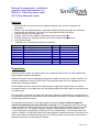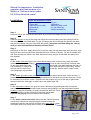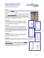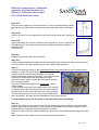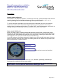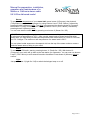
1
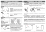
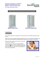
Manual for preparation, installation,
operation and maintenance of a
Malibu or California steam cabin
UK & Eire delivered model
Please read these instructions carefully before you begin assembly / installation.
Malibu steam cabin
California steam cabin
Introduction:
Dear customer,
First of all we would like to congratulate you with the purchase of this MAAX-SaniNova quality
product!
Before you lies the manual for assembly, installation and use of your SaniNova by MAAX steam
cabin. Both currently available models; Malibu and California are described in this manual.
Please read the manual carefully before you begin with
and during the installation.
The differences per model are clearly indicated by
means of an M where relevant, indicating that this part,
instruction or feature is connected with the Malibu steam
cabin. All other parts, instructions or feature adhere to
both California and Malibu.
Page 1 of 9
Manual for preparation, installation,
operation and maintenance of a
Malibu or California steam cabin
UK & Eire delivered model
Part list:
1. Back wall with pre-formed seat and ledge for shampoo etc. Holes for all parts are
pre-drilled.
2. Shower tray with adjustable feet, underneath which the steam generator and electronic
junction box are mounted. The hole for the drainpipe has been pre-drilled.
3. Inspection panel for the bottom tray.
4. Canopy. (Holes for the speaker and Halogen light are pre-drilled M)
5. Chrome shower set, including shower riser rail and shower head with hose.
6. Set of shower doors
7. Assembly box, including all small parts necessary.
Article code
X9070
X9071
X9187
X9188
X9003
X9729
n.a.
n.a.
Description
Pipe clip 12-20 mm.
Pipe clip 20-32 mm.
Bolt M6x40 mm.
Nut M6
Washer M6
Halogen lamp
Speaker
User Manual
Qty.
1
1
14
14
28
1
1
1
Remarks
Malibu only
Malibu only
Preparation:
Clear the location where the steam cabin is to be placed of all furniture or other objects that
might hamper organised installation.
Remove all parts from their packaging and check to make sure they are in good condition. Do
not begin installation if this is not the case! The guarantee does not cover damage once the
steam cabin has been installed.
Check whether the floor is level and solid enough to support the weight of the unit and its’
occupant(s) when in use. Make sure the wall against which the steam cabin is to be placed are
at a right angle.
Ensure that all connections to water and electrical supplies are performed by a registered firm.
Any technical changes to the product or any inadequate connections of water and electricity will
nullify all guarantee provisions.
The electrical connection is in the fitted appliance inlet box. Only an official registered
electrical installations firm may make the connection. The regulations of the local energy
supply company must be strictly observed, as must the provisions of DIN57100 part 701 and
VDE 0100 part 701. The supply must pas through an RCD (residual current detector) with
1_n=30 mA and be protected by a 16A fuse (2.5 mm, 3500W max.). The nominal load of the
cubicle is 2800W. A multi-pole switch with a gap between contacts when open of at least 3 mm
shall be provided to isolate the power circuit. The RCD (at least 4 mm) must be connected to
the place reserved for it (shown by PE labels).
Page 2 of 9
Manual for preparation, installation,
operation and maintenance of a
Malibu or California steam cabin
UK & Eire delivered model
Installation:
Tools and materials needed:
- Adjustable spanner
- Kit gun
- Power drill
- Silicone kit
- Steel drill (8mm HSS)
- Metal file (half) round
- Screwdriver
- 2.5 mm Allen key
- Metal saw
- Phillips screwdriver
- Vaseline
Step 1.
Place the tray in the area where the cubicle is to be fitted and adjust the feet to level the tray.
Step 2.
Place the canopy on top of the back wall. Align the corners making sure the canopy fits flush
with outside face of the back wall. Fix with C-clamps and drill up through the holes in the back
wall into the canopy using an 8 mm HSS drill (steel). Important: wait with fitting the canopy
until you have assembled and fitted the shower doors!
Step 3.
Stand tray on the floor. Apply silicone kit to the rear edge, lift and place back wall onto tray, align
the outer face corners of the back wall with the outer corners of the tray. Fix with C-clamps and
drill down through the holes in the back wall into the tray using an 8 mm HSS drill (steel) and
bolt together.
Step 4.
Fit the steam outlet pipe (this is the 22mm black rubber hose under the tray) from the steam
generator to the back wall fitting
It has to pass through the 2nd large hole
on the right hand side of the
back wall (view back wall from the rear). If
it is necessary to enlarge the
hole when the pipe is tight fitting, do this
using a round or half round
metal file. Secure pipe to steam outlet
using large pipe clip provided.
Step 5.
Fit the steam generator water inlet pipe (this is the 17mm black rubber hose under the tray). It
passes through the 1st hole in the rear right hand side of the back wall (viewed from rear). It will
be necessary to push the control, clipped to the tray support leg, out of the way to gain better
access to the hole. Pass pipe to water valve and tighten pipe clip.
Step 6.
Fit the temperature sensor (the grey wire with a black end) by passing the wire through the
same hole as the steam generator water inlet pipe and pushing it into the temperature sensor
housing. It may be necessary to gently squeeze the wire to a round
shape if difficulty is found in fitting into housing, but do not
squeeze the grey tip as this will break the insulation.
Step 7.
Fit the water control valve wires (these are the 2 spade terminal
connectors). Pass these wires through the same hole as the
temperature sensor and push fit terminals onto water valve, it does
not matter which way round wires connect to water valve.
Page 3 of 9
Manual for preparation, installation,
operation and maintenance of a
Malibu or California steam cabin
UK & Eire delivered model
Step 8.
Disconnect the touch pad (electronic switch pad) from the wire which is fitted to the control box.
Run this wire also through the same hole as the temperature sensor. Fit the touch pad in the
rear panel and re-connect the wire.
Step 9.
Fit the shower handset riser rail. Assemble the support brackets onto
the riser tube, hold assembled riser rail against recess in the back
wall. Mark the 2 holes that will secure the rail to the wall, drill the 2
marks with a 3mm drill, then screw the riser rail assembly to the back
wall using the 2 self tapping screws provided.
Step 10-A.
To start with the assembly of the shower doors, you should
check the position of the screws in the guides of the sliding
door. The head of the screw should not protrude outside the
guide. Adjust if needed. (See figure 1)
Step 10-B.
Place one of the curved rails on the floor with the open side
facing up. Press the door which will remain static (without
handle) into the rail until you hear a click. By positioning the
static door on the far right-hand or far left-hand side in the rail,
you will determine on which side the entrance to the cabin will
be. Now you can press the other rail onto the top of the static
door. (See figure 2)
Step 10-C.
Now slide the sliding door by way of its’ guides into the rails
from the opposite side of the static door. Slide in with the
handle on the outside. (See figure 3)
Step 10-D.
Click the separate standing profile between the ends of the curved rails, in such a
manner that the closed side of the profile is facing the sliding door. (See figure 4)
Step 10-E.
Place the wall profiles to the back wall of the cabin, 1 cm. from
the side of the cabin. Copy the pre-drilled holes onto the back
wall and drill 3-mm holes at these positions. Screw the wall
profiles onto the back wall with the short end facing outwards,
using the screws as included. (See figure 5)
Page 4 of 9
Manual for preparation, installation,
operation and maintenance of a
Malibu or California steam cabin
UK & Eire delivered model
Step 10-F.
Place the door assembly in the wall profiles. Fix it to the wall profiles by drilling
through the pre-drilled holes and by placing the plastic pop-rivets. (See figure
6)
Step 10-G.
Saw the 2 pieces of covering profile to size and click into both rails. (See figure
7)
Step 10-H.
Adjust the sliding door with the screws in the top-guides, in such a manner that
the sliding door is in line with the fixed door and that the handle is parallel to
the wall profile.
(See figure 1)
Step 10-I.
Slightly lubricate both rails using vaseline.
Step 10-J.
Seal the seams between the cabin and the wall profiles using silicone kit. Now you position and
bolt the canopy to the back wall using the 6mm x 50mm bolts provided.
Step 11.
Connect hot and cold supply to the thermostatic mixer valve using flexible pipe (stainless steel
braided or 15mm PVC pipe) ensuring pipe work has been
flushed out first. Connect the waste pipe using 40mm
flexible waste pipe. Make sure the pipe runs lower than the
tee fitting in the waste system otherwise the steam
generator cannot empty, thereby preventing self cleaning
from working properly.
Connect the electrical supply to the control box using a
16amp supply.
Fit the chrome face plate to the thermostatic valve, seal off
around the face plate with silicone kit to the back wall & fit
chrome lever to mixer valve with the lever facing upwards.
This allows easy access to the 2.5 mm Allen screw which,
when screwed in, will align with the indentation in the square spindle.
You should now check for any leaks in the pipe work before final fitting.
Step 12.
Seal off the cubicle by running a bead of silicone sealant around the outside of the wall profiles
and the guide rails top and bottom, ensuring that the thickness of the silicone is approx. 5mm
thick to allow for movement during temperature changes.
Also run a bead of silicone sealant between the joints of the tray and back wall/canopy and back
wall.
When sealing off the cubicle, ensure all surfaces are clean and dry.
Page 5 of 9
Manual for preparation, installation,
operation and maintenance of a
Malibu or California steam cabin
UK & Eire delivered model
Operation:
Shower (model California):
The shower is very simple to operate. Turn the lever to the left, pull back and the water will flow
out of the handset, turn to the right and water will flow out of the body jets, the 2 can be
mixed by moving the lever between left and right to suit personal taste.
To control the water temperature turn the control knob underneath the lever to the desired
temperature and the valve will maintain that temperature (as long as there are no large
pressure drops or shortage of hot water). To go past 38°C, turn the thermostatic valve as far as
it will go, then push in the safety button and continue to turn the control knob.
Steam (model California):
When you want to enjoy a relaxing steam bath, press the on/off button on the round control
panel to the right of the mixer valve. A green LED will indicate when steam is being generated.
A blinking green LED indicates the generator is in the process of shutting off, after which it will
flush itself with cold water (see also the chapter ‘Maintenance’).
A red LED indicates if the steam generator is heating up or filling up with fresh water. See also
picture. Should the red LED start to blink, the steam generator has failed to fill up properly and
has shut itself down for safety reasons.
Green LED
Red LED
After a few minutes the beneficial
steam will flow from the outlet at the lower left corner. Beware: possibility of hot drops
forming at the underside of the steam-outlet!
SUGGESTION: You can place herbal essences or therapeutic oils into the top of the
steam outlet to create a particular steam aroma, befitting your mood.
Page 6 of 9
Manual for preparation, installation,
operation and maintenance of a
Malibu or California steam cabin
UK & Eire delivered model
Shower (model Malibu):
The various options for showering are very simple to operate. By turning the function selection
knob, you can direct the water flow via one of the options. These options are: shower head, 6
side jets, 6 back jets or 3 shoulder jets. Water will always flow at full force.
To control the water temperature turn the control knob underneath the lever to the desired
temperature and the valve will maintain that temperature (as long as there are no large
pressure drops or shortage of hot water). To go past 38°C, turn the thermostatic valve as far as
it will go, then push in the safety button and continue to turn the control knob.
Steam and other features (Malibu):
The Malibu steam cabin will allow you to experience a luxurious steam bath fully programmed to
your personal taste. On top of that you can listen to the radio and switch on the light if required.
1. Alarm
11. Radio On/Off
2. Steam On / Off
10. Frequency
3. Light On / Off
9. Memory
4. Temperature
8. Program
5. Timer
6/7. Plus / Minus
The display:
A: An acoustic signal will sound when the water level in the steam generator is
too low. While filling it will sound at intervals and stop when the level is back to
normal.
B: An acoustic signal will sound when the desired temperature level has been
reached. It will continue until switched off.
C: Furthermore, the button can be used for giving a distress signal.
2. Steam On / Off: Switching steam on or off.
3. Light On / Off: Switching halogen lamp on or off.
4. Temperature: This button is used to start setting the steam temperature.
5. Timer: This button is used to start setting the steam timer.
6. Minus: Decrease time, temperature or radio frequency.
7. Plus: Increase time, temperature or radio frequency.
8. Program: This button is used to initiate programming a steam bath
9. Memory: This button, when pressed twice, will confirm any programming actions.
10. Frequency: With this button you can initiate auto-search of frequencies.
11. Radio On / Off: Switching the radio on or off.
1. Alarm:
Page 7 of 9
Manual for preparation, installation,
operation and maintenance of a
Malibu or California steam cabin
UK & Eire delivered model
Steam:
To program the temperature of your steam bath, press button 8 (Program), then button 4
(Temperature) and set the temperature by using buttons 6 and 7 (Plus / Minus), followed by
pressing button 9 (Memory) twice. The timer is programmed by pressing button 8 (Program),
then button 5 (Timer) and set the time by using buttons 6 and 7 (Plus / Minus), followed by
pressing button 9 (Memory) twice.
You can now start the steam bath by pressing once button 2 (Steam On / Off).
ADVICE: When you begin using the steam cabin, do not start with periods of longer that 10 to
12 minutes at a temperature of 35°C. After several steam baths at these levels and whilst
feeling well, you may safely increase the temperature with increments of 5°C and of 5 minutes
per 2 to 3 usages. The maximum safe temperature of a steam bath is 50°C!
You can place herbal essences or therapeutic oils into the top of the steam outlet to create a
particular steam aroma, fitting to your mood.
Radio:
To control your FM radio, start by pressing button 11 (Radio On / Off). With button 10
(Frequency) your radio will go back to the last station you listened to. You can now use buttons
6 and 7 (Plus / Minus) to auto-search forward or backward. Press button 9 (Memory) twice to
confirm.
Light:
Just press button 3 (Light On / Off) to switch the halogen lamp on or off.
Page 8 of 9
Manual for preparation, installation,
operation and maintenance of a
Malibu or California steam cabin
UK & Eire delivered model
Maintenance:
Acrylic products are very easy to clean and maintain because hardly any dirt remains behind on
the surface. A sponge or soft cloth and possibly a few drops of an anti-static preparation will be
sufficient for routine cleaning. This will make your cabinet fresh and shining again and you will
renew the dirt-repellent properties.
You can use domestic liquid detergent (for example. washing up liquid) to remove obstinate dirt.
Never use any abrasive, gritty cleaning or scouring materials.
After each steam bath the steam generator starts its’ self cleaning process. This process
consists of a rapid in-flow of cold water, to ‘shock’ the system and prevent limescale from
depositing on the insides of the steam generator. Self cleaning drainage will occur through the
steam inlet
Specifications:
Dimensions (WxHxD)
Weight
Minimum water pressure needed
Flow rate
Steam generator
Control operation
Hot and cold inlets
Water valves
Water connection
Thermostatic mixer valve
Temperature sensor
0.9x2.18x0.9 Mtr.
90 Kg.
85.000 Btu / 2.0 Bar
Depends on input and choice of jets / shower head
2.8 kW 220-240 Volt 16 amp required
By touch-button panel
15 mm pipe size
12v DC
40 mm universal compression fitting required,
with flexible waste pipe
5 Bar max. pressure
Set at 55 ° C
Contact:
Should you require assistance, you can contact our After Sales Service at +44 (0)1452 721440
Page 9 of 9