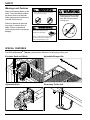
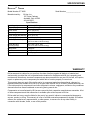
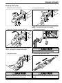
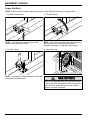
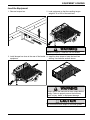
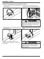
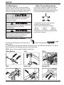
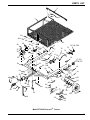
1
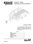
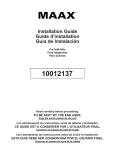
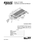
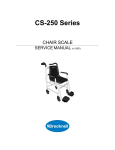
®
Model ET 2000
Operation and Service Manual
te
alaete
rr
ssccaailla
ile
E TTrra
M
Maax
x.. C
Caap
p.. 2
2000
000 lb
lbs.
s.
T
E
ET
000
22000
Load Capacity: 2000 lbs
The ET 2000 ESCALATE ® TRAILER offers ground
level roll-on loading and roll-off unloading of
equipment with non-tilting lowering deck. The
winch driven deck allows one person to load and
unload equipment.
Contents
SAFETY ............................................................... 2
SPECIAL FEATURES .......................................... 2
SPECIFICATIONS ................................................ 3
WARRANTY ......................................................... 3
TRAILER HITCHING ............................................ 5
EQUIPMENT LOADING ....................................... 6
SERVICE .............................................................. 9
PARTS LIST ......................................................... 12
B33-01-0068-01
SAFETY
Warnings and Cautions
Observe all warning labels on the
trailer. The trailer warning labels
are shown here as a reminder.
Other warnings and cautions are
included in this manual.
Failure to observe all warnings
may result in serious injury or
death. Failure to observe all
cautions may result in equipment
damage.
WARNING
Stand clear of trailer while deck is being raised or
lowered. Moving deck will create pinch points
causing serious crushing injury.
WARNING
Stand clear of trailer while deck
is being lowered. Contact with
trailer deck will cause serious
crushing injury.
WARNING
Trailer deck must be fully raised
with transport clamp locked and
pinned before towing trailer.
Failure to comply with these instructions
may result in serious personal injury or
death as well as damage to cargo.
SPECIAL FEATURES
The Bil-Jax ESCALATE ® TRAILER includes all the features of a heavy duty trailer, plus:
Escalator Deck and Winch
Adjustable Bumper Bar
Adjustable Hitch
Stow-away Trailer Jack
2
SPECIFICATIONS
ESCALATE® TRAILER
Model Number ET 2000
Manufactured by:
Serial Number ________________
Bil-Jax, Inc.
125 Taylor Parkway
Archbold, Ohio 43502
419.445.9675
Specifications
Rated Capacity
2000 lbs. (907.2 kg) max.
Weight (Empty)
800 lbs. (362.9 kg)
Overall Width
96 in. (243.8 cm)
Overall Length
148 in. (375.9 cm)
Overall Height (Bed Raised)
32 in. (81.3 cm)
Bed Height (Raised)
13-1/2 in. (34.3 cm)
Bed Size (Flat Surface)
58 in. wide x 72 in. long
(147.3 cm wide x 182.9 cm long)
Overall Bed Size
(Including Ramp)
58 in. wide x 86 in. long
(147.3 cm wide x 218.4 cm long)
Ramp Grade
6 degrees
Hitch Size
2 in. (5.08 cm) ball
Suspension
Leaf Spring
WARRANTY
Bil-Jax warrants its trailers for one year from the date of delivery against all defects of material and
workmanship, provided the unit is operated and maintained in compliance with Bil-Jax’s operating and
maintenance instructions; structural components are also warranted for one year. Bil-Jax will, at its option,
repair or replace any unit or component part which fails to function properly in normal use.
This warranty does not apply if the trailer and/or its component parts have been altered, changed, or
repaired without the consent of Bil-Jax or by anyone other than Bil-Jax or its factory trained personnel, nor
if the trailer and/or its components have been subjected to misuse, negligence, accident or any conditions
deemed other than those considered as occurring during normal use.
Components not manufactured by Bil-Jax are covered by their respective manufacturers warranties. A list
of those components and their warranties is available upon written request to Bil-Jax.
Bil-Jax shall not in any event be liable for the cost of any special, indirect or consequential damages to
anyone, product, or thing. This warranty is in lieu of all other warranties expressed or implied. We neither
assume nor authorize any representative, or other person, to assume for us any other liability in
connection with the sale, rental, or use of this product.
3
This page intentionally left blank
4
TRAILER HITCHING
Hook Up the Trailer
1. Raise trailer and lift ball latch.
2. Line up ball with hitch.
NOTE: The trailer hitch uses a 2 inch ball.
3. Lower hitch onto ball and close ball latch.
4. Raise and secure jack.
Ma
Mxa.
xC. a
Cpa.
p2.0
2000
0l0b
s
lb.
s
.
NOTE: Trailer frame should be level when hitch is
on ball. See page 9 to change hitch height.
Always raise and pin the jack before towing.
5. Hook safety chains.
Always cross safety chains below tongue. Safety
chains must hold tongue up if hitch fails.
5
6. Connect and check trailer lights.
Always check the tail lights and brake lights before
towing.
EQUIPMENT LOADING
Lower the Deck
NOTE: Trailer must be hitched to vehicle according to page 5 before lowering or raising the deck.
1. Lift latch release lever.
2. Lift latch handle.
NOTE: The trailer frame should be on a level
surface when lowering the deck.
NOTE: If the deck pulls against the clamp when the
latch handle is up, the winch brake must be
adjusted. See page 9 to adjust the winch brake.
3. Lift latch clamp.
4. Lower the deck.
Ma
x.
Ca
p.
20
00
lb
s.
NOTE: To prepare for raising the deck, tilt the latch
clamp back onto the handle.
Make sure people are away from the trailer before
lowering the deck. Keep hands and feet away from
deck and rails. Hands and feet can get crushed
between the deck and frame.
6
EQUIPMENT LOADING
Load the Equipment
1. Remove bumper bar.
2. Load equipment so that the resulting tongue
weight is 15 to 20% of the total load.
e
alatatre
sc aialle r
sc aile
Tr
E Tr
Max
Max
.C
. Cap
ap. 20
. 2000
00lb
lbs.
s.
EETT
000
22000
Maximum capacity = 2000 lbs. Do not exceed.
3. Install bumper bar close to the rear of the loaded 4. Install tie-down straps to keep the load from
equipment.
shifting. Use tie-down anchors shown.
e
alat r
sc aile
E Tr
Max
.C
ap
. 20
00
lb
s.
ET
20
00
Always secure the load with tie-down straps before
towing. Failure to properly secure the load may
result in injury, death, or equipment damage.
Do not hook tie-down straps on the roller guides.
7
EQUIPMENT LOADING
Raise the Deck (trailer must be hitched to vehicle)
1. Check the latch clamp. Tilt the latch clamp back
onto the handle.
2. Crank winch handle to raise the deck. Stop
cranking when the deck is aligned with the frame.
Ma
x.
Ca
p.
20
00
lb
s.
Make sure people are away from the trailer before
raising the deck. Keep hands and feet away from
deck and rails. Hands and feet can get crushed
between the deck and frame.
3. Raise the latch handle. Put the latch clamp over
the clamp boss.
NOTE: Do not over tighten winch. Winch is
intended to raise and lower deck — not to secure
load on trailer.
8
4. Push the latch handle down until the release lever
locks.
If not clamped, the deck may fall during travel.
Always clamp the deck before towing. Failure to
clamp the deck may result in injury, death, or
equipment damage.
SERVICE
Adjusting the Hitch Height
The trailer frame and deck should be level for equipment loading and unloading. If the trailer hitch is too
high or too low when hitched to the towing vehicle, readjust the hitch height.
1. Unhitch trailer. Remove hitch mounting screws.
Adjust hitch height when trailer is empty. Use jack
to aid in hitch adjustment.
2. Install hitch in new position.
Failure to install and tighten all hitch mounting
screws may cause serious equipment damage.
Adjusting the Winch Brake
The winch brake should hold the trailer deck up when the equipment load is not more than 2000 pounds.
If the winch brake does not hold the deck up when the winch handle is released, readjust brake tension.
1. Raise the deck.
2. Remove the winch handle and lock nuts.
LOCK NUTS
Ma
x
.C
ap
.2
WINCH HANDLE
00
0l
bs
.
3. Tighten the winch brake adjust nut 1/4 turn.
4. Install and tighten the lock nuts and handle.
WINCH BRAKE
ADJUST NUT
LOCK NUTS
WINCH HANDLE
9
SERVICE
Replacing the Lift Rollers
1. On a paved, level surface, pull trailer onto 2x6
blocks. Jack up and unhitch the trailer.
2. Lower the deck until the front or rear lift rollers
can be removed from the roller access holes.
Ma
1-1/2
x.
Ca
p.
20
The deck must be supported by the paved surface
or shoring before the lift rollers are removed.
3. Use a hex wrench to unscrew and remove the
rollers. Install and tighten new rollers.
NOTE: It is easier to remove and replace one roller
at a time. You can adjust the jack to access each
roller. Loosen set screw first.
10
00
SERVICE
Tire Maintenance
Wheel Torque Requirements
At least once each week, use an accurate tire
pressure gage to check the air pressure in both
trailer tires. Inflate to the pressure recommended
by the tire manufacturer (located on the tire).
It is extremely important to apply and maintain
proper wheel mounting torque on your axle.
Wheel nuts should be retorqued after 50 miles
and 100 miles and periodically there after.
Low or uneven tire pressures will not properly
support a loaded trailer and could lead to
premature tire wear.
When replacing tires, it is important to use a tire
of appropriate size and load rating
(20.5/800X10E).
Failure to maintain proper torque on the lug
nuts may result in the wheel shearing off of the
trailer, possibly causing an accident and
seriously damaging the equipment.
The tightening of the lug nuts should be
torqued in the sequence above.
Lug nuts should be torqued in stages:
Stage 1
Stage 2
Stage 3
25 Ft-Lbs
60 Ft-Lbs
100 Ft-Lbs
This procedure should be followed after each
time the tire is removed.
Lubrication (every 6 months)
Lubricate the following parts with clean motor oil
or wheel bearing grease
where shown.
For additional winch operating and service instructions, refer to the Winch Owner’s Manual. The Winch
Owner’s Manual is in the storage tube at the front of the trailer.
NOTE: Be sure that no grease is applied to brake pad.
Wheel Bearings
Jack
Winch
Ma
Hitch
Deck Latch
x.
C
Bumper Bar
11
PARTS LIST
Item
No.
1
2
3
4
5
6
7
8
9
10
11
12
13
14
15
16
17
17A
17B
17C
18
19
20
21
22
23
24
Part No.
B12-00-0046
B12-00-0053
0089-132
0090-0313
0066-0063
B07-06-5456
B39-00-0023
0090-0051
B12-00-0047
0090-0363
B25-00-0048
0090-0034
0090-0208
0090-0420
B18-00-0109
B06-00-0313
B01-10-0024
B01-10-0023
B01-10-0070
B01-10-0069
B06-00-0317
0090-0005
B29-00-0037
0090-0419
0090-0183
0090-0907
0192-0042
25
26
27
28
29
30
31
32
B32-00-0009
B25-00-0056
0192-0103
0090-0882
B32-00-0011
0090-0881
0090-0278
0192-0097
33
34
35
36
37
38
39
40
0090-0624
B39-00-0024
B07-06-5262
0090-0185
B31-00-0028
B07-06-5263
0090-0037
B06-00-0319
12
Description
Qty
Deck Weldment
1
Load Bar Weldment
1
Spring, Compression
2
Pin, Roll, 3/16 x 3/4
2
Pin, L
2
Plate, Spring Push-Off
2
Spring, Compression, 7/8 in. 2
Screw, Cap, 3/8-16 x 2-3/4
2
Frame Weldment
1
Screw, Set, 1/4-20 x 3/4
4
Roller, Lift
4
Screw, Cap, 5/16-18 x 2
8
Washer, Split Lock, 5/16
8
Washer, SAE Flat, 5/16
20
Fender
2
Decal, “Stand Clear While...” 2
Light Assembly, Left Tail
1
Light Assembly, Right Tail
1
Lamp, Tail Light, GE-1157
2
Replacement Lens
2
Decal, “Escalate Trailer”
2
Screw, Cap, 1/4-20 x 3/4
2
Bracket, License Plate
1
Washer, SAE Flat, 1/4
2
Nut, Lock, 1/4-20
2
Shackle Bolt, 9/16-18 x 3
2
Hub Group,
2
(items 25 thru 27 and 29)
Seal, Bearing
2
Bearing, Wheel
4
Hub, 5 Hole, 4.5 in. BC
2
Washer, Spindle
2
Cap, Hub
2
Pin, Cotter, 5/32 x 2
2
Nut, Castle, 1-14
2
Wheel/Tire Assembly
2
20.5/800X10E
Nut, Wheel Lug
10
Spring, Leaf
2
Plate, Hanger, Leaf Spring
4
Nut, Nylon Lock, 5/16-18
8
Cushion, Leaf Spring
2
Bracket, Leaf Spring Hanger 2
Screw, Cap, 5/16-18 x 2-1/2
8
Decal, ET 2000
2
Item
No.
41
42
43
Part No.
B06-00-0316
B23-02-0036
0090-0344
Description
Qty
Decal, “Max. Cap. 2000 lbs.” 1
Jack, Tongue
1
Screw, Threadcut, #10-24 x
1
1/2
44 B01-01-0120 Harness, Wiring, 20 ft.
1
45 0090-0574
Washer, SAE Flat, 1/2
6
46 0090-0080
Screw, Cap, 1/2-13 x 4-1/2
2
47 0090-0081
Screw, Cap, 1/2-13 x 5
1
48 0090-0192
Nut, Nylon Lock, 1/2-13
7
49 B03-00-0017 Safety Chain Assembly
2
50 0192-0099
Hitch, Ball, 2 in., 3500 lbs.
1
51 0090-0068
Screw, Cap, 1/2-13 x 1-3/4
4
52 B12-00-0049 Hitch Weldment
1
53 Not
Serial Number Tag
1
Replaceable
54 B00-00-0014 Cap, Plastic, 2-1/2 in. Dia.
2
55 0082-0867
Winch, w/o Cable
1
56 0090-0422
Washer, Flat, SAE, 3/8
3
57 0090-0210
Washer, Split Lock, 3/8
7
58 0090-0040
Screw, Cap, 3/8-16 x 3/4
7
59 B04-07-0047 Clamp, Cable 1/4 in.
2
60 B05-03-0001 Cable, Steel, 1/4 in.
7ft.
61 B00-00-0036 Thimble, Cable, 1/4 in. Dia.
1
62 B42-00-0012 Latch, Deck
1
63 B06-00-0314 Decal, “Lock Transport …”
1
64 Purchased with Pin, Retaining
1
jack (item 43)
65
66
67
68
69
70
71
B06-00-0312
0090-0906
0090-0429
B26-00-0016
0090-0770
B36-00-0027
B29-00-0147
72 B01-10-0021
72A B01-10-0066
72B B01-10-0068
73 B29-00-0146
74 B01-10-0022
74A B01-10-0067
74B B01-10-0068
Decal, “Stand Clear ...”
Shackle Nut, 9/16-18
Washer, SAE Flat, 1 in.
Pulley
Pin, Cotter, 3/16 x 1-1/2
Pin, Pulley
Bracket, Side Marker Light,
Left Front/Right Rear
Light, Side Marker,
Left/Right Front – Amber
Replacement Lens – Amber
Lamp, Side Marker
Bracket, Side Marker Light,
Left Rear/Right Front
Light, Side Marker,
Left/Right Rear – Red
Replacement Lens – Red
Lamp, Side Marker
2
2
1
1
1
1
2
2
2
2
2
2
2
2
PARTS LIST
2
3
4
5
1
70
69
68
59
8
67
60 62
58
74,74A,74B
59
57
56
9
58 10
57
61
59
15
7
6
73
74
11
14 71 72
55
16
13
17,17A,
17B,17C
12
63
54
72,
72A,
64 72B
66
65
18
53
17
17
22 21
52 48
48
51
23
45
00
44 43
45
50
47
ET
20
39
41
45
46
40
Ma
x.
Ca
p.
20
00
lb
s.
14
19
20
25
26
27
26
31
24
28
38
37
29
30
42
34
49
te
ala r
sc aile
E Tr
36
32
33
35
14
Model ET 2000 ESCALATE ® TRAILER
13
125 Taylor Parkway
Phone 419-445-9675
Archbold, OH 43502
Fax 419-445-0367