1
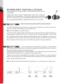
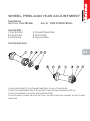
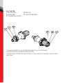
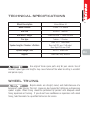
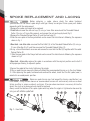
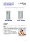
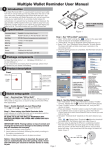
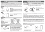
USER’S MANUAL
AND INSTRUCTIONS
Installation Instruction
En
Instrucciones de Instalación
Sp
Instructions de Montage
Fr
Istruzioni di Montaggio
It
Montageanleitung
De
安裝
Ch
取り付方法説明
Ja
User’s Manual and Instructions
Installation instructions
Warranty
Wheels package
Wheelset installation
Wheel Preload Hub Adjustment
Technical specifications
Spoke replacement and lacing
Maintenance recommendations
Wheel replacement parts
02
02
05
06
07
09
10
12
14
En
02
INSTALLATION INSTRUCTIONS
Congratulations on your Vision product. Please read these instructions and
follow them for correct use. Failure to follow the warnings and instructions
could result in damage to product which is not covered under warranty, damage
to bicycle or cause an accident resulting in injury or death. Since specific tools
and experience are necessary for proper installation, it is recommended that the
product be installed by a qualified bicycle technician.
WARRANTY
Full Speed Ahead (FSA) warrants all FSA, Gravity, Vision, Metropolis and RPM
products to be free from defects in materials or workmanship for a period of
two years after original purchase unless otherwise stated in the full warranty
policy. The warranty is non-transferable and valid to the original purchaser of
the product only. Full warranty policy is available at:
FULLSPEEDAHEAD.COM WARNING
Regularly check the wheels to be certain they are fastened
securely to the bicycle fork. If the Quick Release is not installed correctly, the wheel
may become separated from the fork and result in an accident, personal injury or death.
03
WARNING
Tires mounted on clincher wheels should not be inflated
above 125 psi. (8.5 bar). Tires mounted on tubular wheels should be inflated per tire
manufacturer recommendations.
Carbon fiber rims require special brake pads to guarantee
proper braking performance. Use only Vision brake pads with Vision wheels. Using other
brands of brake pads can damage the rim and cause an accident, personal injury or
death. Using other brands of brake pads will void the Vision Warranty.
WARNING
WARNING
Inspect the brake pads frequently for metal ships or other
foreign debris. Metal debris and foreign objects in the brake pad will cause compromised
braking performance and severe rim damage that may result in wheel failure and cause
accident.
WARNING
Rims wear with use. Check the braking surface of rim
frequently and replace if worn. Riding with a worn rim may cause wheel failure and
serious accident resulting in injury.
En
04
METRON 81
(VT-880 / VT-880CH)
PRODUCT
ITEM CODE
VISION METRON 81 Tubular VT-880 Wheelset Shimano Red Decal
710-0159
VISION METRON 81 Clincher VT-880CH Wheelset Shimano Red Decal
710-0158CH
VISION METRON 81 Tubular VT-880 Wheelset Shimano Grey Black Decal
710-0159BKG
VISION METRON 81 Clincher VT-880CH Wheelset Shimano Grey Black Decal
710-0158CHBKG
VISION METRON 81 Tubular VT-880 Wheelset Campagnolo Red Decal
710-0118
VISION METRON 81 Clincher VT-880CH Wheelset Campagnolo Red Decal
710-00020152031
VISION METRON 81 Tubular VT-880 Wheelset Campagnolo Grey Black Decal
710-0118GS
VISION METRON 81 Clincher VT-880CH Wheelset Campagnolo Grey Black Decal
710-00020152030
VISION METRON 81 Tubular VT-880 Front Wheel Red Decal
710-0347CH
VISION METRON 81 Clincher VT-880CH Front Wheel Red Decal
710-0347BKG
VISION METRON 81 Tubular VT-880 Front Wheel Grey Black Decal
710-00020152030
VISION METRON 81 Clincher VT-880CH Front Wheel Grey Black Decal
710-0347CHBKG
VISION METRON 81 Tubular VT-880 Rear Wheel Shimano Red Decal
710-0348
VISION METRON 81 Clincher VT-880CH Rear Wheel Shimano Red Decal
710-0348CH
VISION METRON 81 Tubular VT-880 Rear wheel Shimano Grey Black Decal
710-0348BKG
VISION METRON 81 Clincher VT-880CH Rear wheel Shimano Grey Black Decal
710-0348CHBKG
VISION METRON 81 Tubular VT-880 Rear wheel Campagnolo Red Decal
710-0349
VISION METRON 81 Clincher VT-880CH Rear wheel Campagnolo Red Decal
710-0349CH
VISION METRON 81 Tubular VT-880 Rear wheel Campagnolo Grey Black Decal
710-0349BKG
VISION METRON 81 Clincher VT-880CH Rear wheel Campagnolo Grey Black Decal
710-0349CHBKG
WHEELS PACKAGE
05
A. Wheels
B. Wheels bag
C. Accessories bag + Instructions
D. Quick Release (QR)
E. Brake Pads
F. Valve Extensions (only VT-880)
G. Spoke Protector
WARNING
Vision Spoke Protector is intended to prevent the chain from
falling down in the spokes. Please install it on the rear wheel before riding.
En
E
F
G
WHEELSET INSTALLATION
06
1.For mounting tires, carefully follow the instructions provided by the tire
manufacturer.
2.Apply light grease onto the Freehub Body. Install the cassette per
manufacturer’s recommendations. The Shimano freehub body is compatible
with S11 cassette. A spacer (A) is required when mounting S9 & S10 cassette.
The Campagnolo Freehub Body is compatible with C10 and C11 cassettes.
WARNING
A
Do not use Vision carbon specific pads with non carbon (alloy) rims.
3. Insert the Quick Releases into the wheel. The lever of the Quick Releases should go on the nondrive side. Thread the Quick Release nut, but do not tight.
Note: Front Quick Release is shorter than rear.
4. Install the Front and Rear Wheel into the drop-outs of the fork and frame. With the QR lever in
the open position, tighten the QR until it is in contact with the frame or fork dropouts. Close the QR
lever. The QR lever should require substantial effort to close the last 25-30 degrees. If it closes with
only moderate hand pressure, the QR must be readjusted by opening the QR lever, then turning the
QR nut clockwise until the closing action of the QR lever requires the recommended force.
WARNING
• If you are unfamiliar with Quick Release assembly it is recommended to
ask for advice from your local bike shop. Riding with an improperly assembled Quick Release can cause the
wheel to shift while in use resulting in accident and injury.
• Regularly check the QR adjustment. If the Quick Release is not installed correctly, the wheel may become
separated from the fork and result in an accident, personal injury or death.
• Always close the skewer lever completely. Do not allow a frame or fork tube or any other member to
inhibit full lever travel when closing. Failure to close the lever completely will limit cam engagement and the
skewer’s ability to hold the wheel in place.
Note: The QR must be periodically lubricated at the pivot points so it can exert maximum sideways force.
WHEEL PRELOAD HUB ADJUSTMENT
Specification
Model Name Vision PRA Hubs
Front Hub ASM:
1. Front Hub Shell
2. Front Hub Axle
3. Axle End Cap
Model No. VT-880 VT-880CH PRA Hubs
07
4. Threaded Preload Collar
5. M3 Pinch Bolt
6. Alignment Collar
Front Hub Adjustment
En
1.Unscrew the Pinch Bolt (5) in the Threaded Preload Collar (4) using a 2.5mm Allen Key.
2.Tighten the Threaded Preload Collar (4) by-hand until it stops, then back-off (loosen) by 1/8th turn.
3.Screw in the Pinch Bolt (5) and tighten with the Allen Key to 2Nm.
4.Install the wheel in the bike and ensure that there is no lateral (side-to-side) movement and that the wheel
rotates freely.
08
Rear Hub ASM:
7. Rear Hub Shell
8. Axle End Nut
9. Threaded Preload Collar
10. Rear Axle
11. Freehub Preload Nut
1.Unscrew the Pinch Bolt (5) in the Threaded Preload Collar (9) using a 2.5mm Allen Key.
2.Screw in Pinch Bolt (5) and tighten with Allen Key to 3Nm.
3.Install the wheel in the bike and ensure that there is no lateral (side-to-side) movement and that the wheel
rotates freely.
TECHNICAL SPECIFICATIONS
Wheel Description
Vision Metron 81
Model number
VT-880 / VT-880CH
Rim size
633x24 / 700x16C
Rim width / height
24mm x 81mm / 25mm x 81mm
Tire type
Tubular / Clincher
Spokes Lengths / Number x Pattern
Front 233 / 18x0 radial
Rear Left 233 mm / 7x0 radial
Rear Right 235 mm /14x2
Spokes Gauge / End
AE-14 / Direct Pull
Nipples
15mm ABS Alloy, external
WARNING
Use original Vision spare parts only for your service. Use of
incorrect spoke types and lengths may cause failure of the wheel resulting in accident
and person injury.
WHEEL TRUING
CAUTION
Bicycle wheels are straight, round, and stable because of a
balance of spoke tension. The rim’s shape can be changed by tightening and loosening
spoke’s nipples. Wheel truing should be performed by persons with adequate wheel
truing experience or training. If you do not have confidence or experience with wheel
truing, take the wheels to a qualified technician for service.
09
En
10
SPOKE REPLACEMENT AND LACING
CAUTION
Before replacing a spoke, please check the above technical
specifications for the correct spoke length and type. Always use original Vision spare parts before
proceeding with the replacement.
1.Remove the spoke and nipple to be replaced
2.Front hub: unscrew the axle end cap (3) using a 5mm Allen wrench and the Threaded Preload
Collar (4) using a 2.5mm Allen wrench; and remove the axle end cap by hand (Fig.1)
3.Remove the Threaded Preload Collar (4) and the front axle (2)
4.Slide the new spoke in the flange hub hole and re-mount the hub internals following the sequence
shown in Fig.1
En
5.Rear hub - non drive side: unscrew the Pinch Bolt (5) in the Threaded Preload Collar (9) using a
2.5 mm Allen Key (Fig.2) and then unscrew the Threaded Preload Collar (9)
6.Using a 5mm Allen wrench unscrew and remove the rear Axle End Nut (8) together with Threaded
Preload Collar (9)
7. Slide the new spoke in the flange hub hole and re-mount the hub internals following the sequence
shown in Fig.2
8.Rear hub - drive side: replace the spoke in accordance with the original position and install it
with proper positioning to adjacent spokes.
9.Secure the spoke to the rim by tightening the nipple
10.Use a spoke tension measuring device to follow the recommended tension as in the chart below
11. After replacing the spoke, tensioned and centered the wheel, check that the flat spoke (aero) is
oriented in an aerodynamic position.
WARNING
Maximum spoke tension must not exceed the tension specification (see
chart below). Using tension above max recommended tension will void warranty and cause wheel
failure resulting in serious accidents and injury. If tension above maximum is necessary to true the
wheel, the rim may be damaged and should be replaced.
Always avoid the rotation of the spoke (spoke wind-up) when the nipple is tightened or loosened by
using an anti-rotation spoke tool.
Fig. 1 – Front hub
Fig. 2 – Rear hub
RECOMMENDED SPOKE TENSION
Front Wheel
Rear Wheel
11
Left&Right Side
Left Side
Right Side
90-110 Kgf
80-100 Kgf
100-120 Kgf
REPLACEMENT OF THE FREEHUB BODY
1.Unscrew the fixing nut by turning it clockwise with a 17 mm wrench while holding the
axle steady with by a 5 mm Allen key.
2.Remove the freehub body from the axle carefully to avoid damaging the spring or
ratchet pawls.
3.Insert the new freehub body on the axle and turn the body till the all ratchet pawls are
in line with the pawl seats in the hub, and then fully insert the freehub body.
4.If necessary, add low-friction grease to preserve the freehub body mechanism.
5.Holding the axle steady by 5 mm Allen key, tighten the fixing nut with a 17mm wrench
to an approximate torque of 8 Nm.
6.It is recommended to apply a thin layer of medium strength thread locker on the axle
then tighten the fixing nut that hold the freehub body.
NOTE: Vision Wheels can be changed from Shimano to Campagnolo compatible (and vice
versa) by replacing the freehub body.
En
12
WHEEL MAINTENANCE
RECOMMENDATIONS
It is the user’s responsibility to examine the product on a regular basis to determine
the need for service or replacement. Cyclists should inspect their bicycle and parts on
a regular basis in order to detect damage that may have occurred from normal use or
for missing parts. Check all parts for damage and wear before every use. Should any
problems or concerns arise, discontinue riding the bicycle and have it inspected by a
qualified bicycle technician.
WARNING
Using wheels that have not been installed or centered correctly,
present broken, damaged, or has missing parts may fail or cause rider to lose control of
bicycle leading to accident, resulting in personal injury or death.
HUB MAINTENANCE
Vision hubs are equipped with high grade, precision, sealed cartridge bearings. Due
to varying factors it is important to have the hub bearings inspected and maintained
periodically. The recommended service intervals are:
• Inspection after each riding season, one calendar year, or 8,000 to 10,000 Km,
whichever comes first.
• After use in rain, storm, muddy, and wet conditions
• Anytime rotational smoothness, signs of corrosion, damage to rubber seals and bearing
covers is apparent.
Tech Tips:
• Avoid getting solvents, aerosol lubricants (as for chain), and strong cleaning solutions
on the hubs. The solvent can wick passed the seals and break down the bearing grease.
• When washing the bike, use only mild soap and a gentle stream of water for rinsing.
Always avoid pressure washing. Such systems can direct super heated water with special
wetting agents at 10X atmospheric pressure, forcing water passed the bearing seal and
removing vital bearing grease.
CAUTION
Since specific tools and experience are necessary for hub
maintenance, it is recommended that the service should be done by a Vision Authorized
Service Center.
Please contact the Authorized Vision Distributors and Warranty Service Centers closest to
your country of residence. A list of Authorized is posted at VISIONTECHUSA.COM.
RIM MAINTENANCE
-When braking, especially during descents, use both front and rear brakes. Front and Rear
brakes have different benefits and limitations, so use them according to instructions
from an experienced rider. It is important that both rims are employed during descents
to properly dissipate heat.
-When riding in wet or dirty conditions, listen for scraping sounds that might indicate
soil or grit is trapped in the brake pad. If so, the pad will be less effective for stopping
and extra abrasive against the rim. Stop, remove the wheel and inspect the pad surface.
Remove any debris before it damages the rim brake surface.
-Water on the rim and brake pads will reduce brake effectiveness. In the wet, allow extra
distance for stopping.
-Vigorous braking will cause brake pads to melt and mark the rim brake track. Do not
allow melted pad material to accumulate on the rim surface. Pad deposits should be
removed with care using a slightly abrasive pad and alcohol. Be careful to keep solvents
from reaching the tire or the rim cement that securing the tire. Pad material on the rim
brake track can interfere with brake response, cause vibration, and create hot spots that
could damage the rim.
-If, during frequent inspections, noticeable impact damage or any other deformation of
the rim is apparent, discontinue use and immediately seek advice from an experienced
mechanic. If an experienced mechanic is unavailable, contact Vision directly at
VISIONTECHUSA.COM.
TIRE GLUING
Before installing the tubular tire carefully read the instructions from the tire manufacturer.
For proper glue bonding, clean the rim with acetone or denatured alcohol, and lightly
scuff the gluing surface with 240-320 grit sandpaper.
To prevent damage to the tire and rim, do not use any tools to install or remove the
tubular tire.
WARNING
In the event of a bicycle accident, discontinue riding the
bicycle until it has been thoroughly examined by a qualified bicycle mechanic, and any
damaged parts replaced.
13
En
WHEEL REPLACEMENT PARTS:
Replacement parts are available for purchase through all bicycle service and retail
locations. If the bicycle shop does not stock the necessary parts, it can be ordered by
the retail location from a VISION distributor or VISION directly. A list of distributors is
available at VISIONTECHUSA.COM.
CONTACT
If you have questions, please visit our web site contact page at:
VISIONTECHUSA.COM.
Notes: Specifications of product may be changed or improved for performance. Please
refer to website periodically for technical updates and revised instructions. Printed in
Taiwan.