1
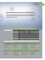
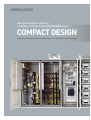
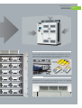
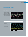
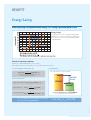
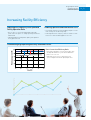
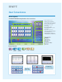
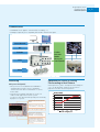
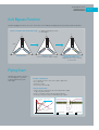
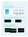
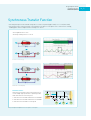
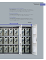
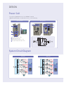
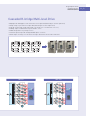
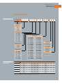
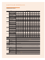
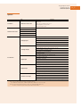
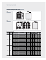
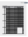
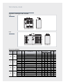
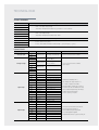
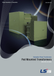
Energy Saving Drive Solution
LS Medium Voltage Drive
LSMV-M1000/M1000A
3kV 200kVA~3,700kVA
4kV 250kVA~4,700kVA
6kV 400kVA~7,500kVA
10kV 600kVA~11,000kVA
11kV 660kVA~12,500kVA
Leading You Toward
a Greater Future Than
You Imagine
Leaping Beyond Being Korea’s No.1 into a Global Top
Company in Industrial Electric / Electronic Solutions /
Materials & Energy Sectors
Greater Value Together
LS Group, a leader of the electric/electronic and energy sectors began as a LG Group’s spin-off in 2003.
LS Group is growing again into an organization delivering the best quality and excellent product development
insight, and customer-centric total solution packages. Company's mission of becoming the global leader in the
industry is to find the reason for its existence in standing and rising together with its customers.
Energy Saving Drive Solution
LS Medium Voltage Drive
LSMV-M1000/M1000A
Innovator of Power Solutions & Automation Systems
LSIS, a global leader in industrial automation systems and power solutions, provides customers with total solutions.
LSIS is building win-win relationships with power transmission/distribution, electric power devices, automation
systems, and smart-grid customers with future-oriented technologies and environment-friendly products
that maximize energy efficiency.
02_03
OVERVIEW
Contents
Introduction
06
Benefit
10
Function
16
Design
20
Selection & Ordering Data
24
Technical Data
28
Appendix
34
Worldwide Network
38
LSIS Leads You to the
Advanced Industry!
Energy Saving Drive Solution
LS Medium Voltage Drive
LSMV-M1000/M1000A
Optimum MV Drive Solution for Industrial
Plants & SOC Systems
Energy
Saving
Compact
Size
High
Reliability
User-centric
Interface
LSIS medium voltage drive consists of compact integrated systems built on cutting-edge technologies,
delivering optimum energy-saving solution featuring high efficiency and power factor. The system supports
a user-friendly HMI(Human Machine Interface) that allows easy operation and displays desired information
for customers maximum convenience. LSIS medium voltage drive offers leading industrial drive solutions
with proven reliability and economic viability. It also contributes to energy saving and environment
protection in various industries including gas, water treatment, marine, power generation, and cement.
04_05
INTRODUCTION
LSMV-M1000
LSMV-M1000A
Energy Saving Drive Solution
LS Medium Voltage Drive
LSMV-M1000/M1000A
Energy Saving Drive Solution
LS Medium Voltage Drive
LSMV-M1000/M1000A
Customized Solutions for Various Industrial Sectors
LSIS' medium voltage drive offers customized solutions incorporating
customer requirements and drawing upon its proven reliability in
various industrial sectors.
Series Overview
MV Drive Series
LSMV-M1000
LSMV-M1000A
Voltage
3kV/4kV/6kV/10kV/11kV
3kV/6kV
Capacity
200kVA~12,500kVA
200kVA~1,200kVA
Control Mode
IP Class
V/F, Sensorless Vector
Standard IP21 (~IP42 Optional)
Standards
CE, UL(Pending)
Frequency
50/60Hz
Topology
Multi-Level PWM
Major Application Domains
Oil & Gas
•Electric submersible pump
•Reciprocating/Centrifugal
compressor
•Conveyor
•Unloading & booster pump
Marine
•Thrusters
•Conveyor
•Vessel propulsion
•Pump
Water Treatment
•Inlet/outlet pump
•Auxiliary pump
•Defoaming pump
•Booster pump
Chemical & Plastic
•Extruder •Mixers
•Coker & wet-gas
compressors
•Stirring machine
•Heat exchanger pump
Power Generation
•Boiler feed-water pump
•Condensation pump
•Cooling water pump
•District heating water
circulation pump
•Primary and secondary air fan
•Coal mill and conveyor
Cement
•Kilns
•Cement mills
•Raw mills •Crushers
•Exhaust fans
•Main & auxiliary fans
Metal
•Furnace fan
•Fluid transfer pump
•Conveyor
•Sludge pump
•Quenching pump
Paper-making
•Boiler fans •Chippers
•Auxiliary pumps
•Chip refiners
•Vacuum pump
06_07
INTRODUCTION
Energy Saving Drive Solution
LS Medium Voltage Drive LSMV-M1000A Series
COMPACT DESIGN
Minimizing Installation Footprint and Investment Costs by an Optimized Drive Design
Energy Saving Drive Solution
LS Medium Voltage Drive
LSMV-M1000/M1000A
Front-access Maintenance
The rack-in type is constructed with a simplified cell, allowing users to access
the drive from the front for maintenance. This eliminates need for additional
space in the rear reducing the product installation footprint.
Input/Output
Connection
Rack In
Low-noise Fan
M1000A product uses a fan that has a drastically reduced noise level, supporting
0~10V speed control through its built-in PID control.
08_09
BENEFIT
Energy Saving through Efficient Energy Management
LSIS’ medium voltage drive demonstrates a unique compact system
built upon optimal design. It is easy to install and constructed to not require
input/output filters, offering high efficiency and energy saving benefits.
Energy Saving Drive Solution
LS Medium Voltage Drive
LSMV-M1000/M1000A
Improved Power Quality
Improved Input Power Quality and THD (Total Harmonic Distortion)
by Adopting Multi-winding Phase-shift Transformer
•Application of extended delta-type
transformer and separated-type
multi-pulse rectifier drastically reduces
input power THD, hence complying with
IEEE-519 standard.
•Input current almost identical to sine
waves eliminates need for additional
harmonic filters or active filters on the
input side.
Input Voltage
Input Current
Producing Multilevel PWM-type Sinusoidal Output
•Compatible with conventional motors
and cables to ensure it fits in with
existing system design
•Minimal impact of voltage reflection,
allowing longer cable length between
drive and motor
•Medium voltage drives minimize
mechanical stress on motor,
eliminating need for additional sine
wave filters.
Output Voltage
Output Current
10_11
BENEFIT
Energy Saving
Achieving Energy Saving and Minimum Energy Loss through Optimized Speed Control
Energy Saving
The optimum way to save energy from fans, pumps,
and blowers is to control the motor speed with drive.
This is far more effective in energy saving than fluid
control by damper.
Example of Operating Conditions
(1) Motor in use: 3300V, 600kW, 6P (Motor efficiency: 95%)
(2) Operating at 60% of air flow volume (Motor efficiency of 90% at 100% of flow volume)
1. Inlet-side Damper Control Power (A)
1
347.4kW....(1)
0.95 Motor Efficiency
600 0.55
3. Energy Saving
Drive-enabled annual energy saving [(1)-(2)]
Note) 0.55: Power rate required for damper’s suction control
when operating at 60% of air flow volume
203.8kW
Saved
2. Drive Control Power
Rated Motor Output (C)
600 (0.6)3 129.6kW......(1)
347.4kW
143.6kW
Motor Input Power
Drive Input Power(B)
129.6
1
136.4kW
0.95 Motor Efficiency
136.4
1
0.95 Drive Efficiency143.6kW......(2)
The electricity bill that can be saved per year assuming
an electric power tariff of KRW55/kW
(347.4-143.6)kW 8,000h
1,630,400kWh
(Assuming 8,000 hours annual operating time)
1,630,400 55
$ 81,520
Energy Saving Drive Solution
LS Medium Voltage Drive
LSMV-M1000/M1000A
Increasing Facility Efficiency
Improving the Productivity with Optimized
Facility Operation Ratio
• Effective process control through prompt and flexible
speed control in response to change operating environment
and demand
Reducing Operation and Maintenance Costs
• Soft starting eliminates network instability and process risks
from starting current and voltage drop.
• Reducing maintenance frequency and costs with decreased
motor stress and extended equipment service life.
• Improving productivity and product quality with optimized
facility operation ratio.
Guaranteeing High Operating Efficiency and Power Factor
Power Conversion Efficiency Ratio
• Delivering a high power factor at 95% or above with
an independent built-in system without additional
power factor corrector
• Improving system efficiency with a drive-only
system configuration without input/output filters
12_13
BENEFIT
User Convenience
Monitoring(HMI)
Standard HD HMI Monitoring Maximizes User Convenience
•12.1 inch touch screen
•Supporting multi languages
(Korean,English,Chinese,Russian,
Spanish, Thai, and Portuguese)
•Control and system state
monitoring
•Powerful data control
(data logging, diagnostics, and
information)
•User-centric convenience
(HD display, high data throughput,
user-friendly interface)
•Supporting dedicated editor for
changing display items(Optional).
5
1
2
6
7
1
3
2
3
4
5
4
6
7
MVD Model Name
Cell Mode
MVD Operation
Menu Selection
Power/Fan
Temperature Display
MVD Mode
External Interface
Ethernet I/F
History
Serial I/F
(RS-232C)
Serial I/F
(RS422/485)
USB I/F
CF card I/F
Parameter
V2Cell is in
Bypass Mode
Extension port
Trend
U3 and W5 Cells
are in Failure Mode
Energy Saving Drive Solution
LS Medium Voltage Drive
LSMV-M1000/M1000A
Communication
•Standard built-in PLC supports customization (I/O extensibility, etc.)
•Providing the improved system compatibility with field-bus communication options
Control Network
PLC
Profibus
DeviceNet
Modbus
Metasys N2
LS BUS(RS485)
Field Bus
Drive
Motor
Optimized PID Control of Cooling
Fan According to Heat Release
Monitoring
MV System View(Option)
•MV System View is a PC (Windows XP and Window 7 compatible)-based software that uses RS485/232
communication links between MVD and PC to control/
monitor MVD.
•Communication standards and a built-in system view
enables flexible application in various systems.
It facilitates remote operation and operating state monitoring
by higher-level systems.
Basic drive operation information
display
Normal reverse direction, stop
command buttons and LED display
Touch-based keypad configuration
Real-time drive information is
displayed in 4 channel graphs,
providing the monitoring stop trigger
Configuring/monitoring history
(operation, failure data), parameter
(drive parameter setup) and communication Selection (communication setup)
Reducing fan noise, power consumption and extending fan
service life by optimizing cooling fan speed control in
proportion to the drive internal temperature
14_15
FUNCTION
Improving Reliability through Various Control Functions
LSIS’s medium voltage drives offer highly reliable optimum solutions
by providing sensorless vector control, flying start, ride-through,
and many more functions.
Energy Saving Drive Solution
LS Medium Voltage Drive
LSMV-M1000/M1000A
Cell Bypass Function
Automatically bypass of failed cells if cells connected in series randomly fail during operation, allowing continuous operation.
Operate Cell Bypass Function (In Auto Setup) •F : Bypass following cell failure
•B : Auto bypass
U
U
U6
U6
U6
U5
U5
U5
U4
U4
U4
U3
U3
U2
U2
V3
4
V5
V5
5
W
V6
6
W
W
V6
4
6
W
V
Condition 1) U2 Fails
Restart after automatic bypass of V2/W2
F
V4
V4
W
W
5
W
V6
V1
V1
V3
3
3
4
V4
W
W
3
V5
2
2
V2
W
W
W
6
W
W
1
1
1
2
5
W
V
W
W
W
W
W
Normal Operation
120
B
B
V2
120
B
F
U1
V1
120
W
U2
U1
V3
Cell By-Pass
U1
U3
F
V2
6600V
U
V
Condition 2) Additional Failure Occurs in
V/W Phase Excluding U Phase
V2 Bypassed at discretion is returned
to normal mode
Flying Start
Automatically estimates speed of
the rotating motor to reach the
frequency without any system
failure(trip)
Example of Flaying Start
•Select flying start at the same time as power application
•Reset after trip
•Automatic restart
•Restart after ride-through
Quick Speed Estimation
•Reduce speed estimation time by controlling the drive output
frequency speed reduction
•Reduce estimation time by reducing output frequency
•Reducing estimation time by controlling voltage response
Drive Output
Frequency
Target Frequency
Motor Speed
Drive Output Voltage
Output Frequency
Output Voltage
Output Current
16_17
FUNCTION
Ride-through Capability
Mechanical energy of load is regenerated to continue operation for up to 5 cycles when power outage occurs. It allows
continuous operation without stopping the drive or system.
Improving Power
Quality and
Reducing Industrial
Damage
•Unpredictability
•Irregularity
•Response to force
majeure events
MV drive output current
MV drive input voltage
▶
◀
Ride-through time
Anti-current Hunt Algorithm in Resonance Area
Continuous drive operation possible in the resonant area followed by application of the drive
Residual current
hunting makes
continuous operation
not possible
Output Current
Continuous
operation possible
in spite of residual
current hunting
Output Current
Output Frequency
Output Frequency
Residual area avoidance function not applied
Resonant area avoidance function applied
Sensorless Vector Function
Improved Starting Torque and Accurate Torque Control
Powerful sensorless algorithm improves speed and torque control precision in low-speed area
Output Current
Output Current
Output Current
Output Current
Output Frequency
Output Frequency
V/F control
Sensorless vector control
Auto-tuning function
Energy Saving Drive Solution
LS Medium Voltage Drive
LSMV-M1000/M1000A
Synchronous Transfer Function
•Switching motor power from medium voltage drive to commercial power (bypass mode) or vice versa (drive mode)
•Synchronous transfer function performs synchronization of the phases of two power sources while motor is running,
enabling power transfer and prevention of ensuing over-current
•Short up/down transfer time
•Ensuring reliability with over-current
Commercial
line operation
LSMV line operation
Power source duplication section
LSMV output U phase current
Medium Voltage Motor Input
U Phase Current
Inv mode → Grid mode(Up)
Commercial line operation
LSMV line operation
Power source duplication section
LSMV output
U phase current
Medium voltage motor input
U phase current
Grid mode → Inv mode(Down)
Multi Motor Transfer
Multi-motor synchronous transfer function allows users
to start multiple (up to 3) MV motors sequentially in drive
mode and control the last motor speed
1. Start M1 motor in Inv Mode and transfer it to Grid Mode
2. Start M2 motor in Inv Mode and transfer it to Grid Mode
3. Start M1 motor in Inv Mode to control speed
Inv mode
Grid mode
Possible to control
the speed of the
last motor
MVD
Reactor
Yes/No
M1
Note) Delivering uninterrupted motor current requires reactor option.
M2
M3
18_19
DESIGN
LSMV-M1000/M1000A Series!
Next Generation Motor Drive Solutions Enabling
Energy Saving in Various Industrial Domains!
Multi-winding Phase-shift
Transformer Module
Master Control
Module
Energy Saving Drive Solution
LS Medium Voltage Drive
LSMV-M1000/M1000A
Multi-winding Phase-shift Transformer
•Multi-winding phase-shift transformer (36 pulse/18 winding) is in place with taps for
change in input voltage.
•Reducing power harmonics with multi-pulse filtering in compliance with IEEE standards
•Eliminating need for harmonic filter and power factor-improving condenser
Master Control Module
•Master control module to control multi-level PWM output voltage with a total of 18 unit
cells and fiber optic communication link.
•User-centric system view to support system diagnostics and monitoring
Cell Drive Module
•Six low-voltage single-phase drives in serial connection per phase, generating 25 level
3 phase output voltage. It is designed to ensure easy cell maintenance.
•Each cell performs PWM switching in distributed control mode and has default built-in
cell protection and bypass functions.
Cell Drive Module
At 6.6kV
20_21
DESIGN
Power Cell
•Cell-specific keypad allows users to check individual cell details
•Additional R/S/T and P/N check PIN allows for safe cell state monitoring
Cable Type Cell
Bus Type Cell
1
2
1
3
4
2
3
1 Fiber Optic Board (Cell side)
2 Output Terminal (T1, T2)
3 AC630V, Input Terminal (L1, L2, L3)
4 Fiber Optic Board (Control panel side)
System Circuit Diagram
3kV Class
4kV Class
Energy Saving Drive Solution
LS Medium Voltage Drive
LSMV-M1000/M1000A
Cascaded H-bridge Multi-level Drive
•Adopting multi-winding phase-shift transformer lowers input THD (Eliminating the need for input filters)
•Multiple voltage steps allow lower output THD (Eliminating the need for output filters)
•Reducing common mode voltage and leakage current (Effective to extend motor service life)
•Enabling complete modularization of power module circuits
•Modular design makes easy voltage increase
•Continuous operation possible through individual power cell failure
•Minimal impact of voltage reflection allows for longer cable distance between drive and motor
6kV Class
10kV Class
10
10
10
22_23
SELECTION AND ORDERING DATA
User-centric Customized Solutions
With its proven reliability and perfect green energy solution,
LSIS MV Drive fully satisfies the needs of each and every customer.
Energy Saving Drive Solution
LS Medium Voltage Drive
LSMV-M1000/M1000A
Ordering Data
Model Number
LSIS Medium
Voltage Drive
Series
1000
1000A
Input Voltage
030 : 3.0[kV]
033 : 3.3[kV]
041 : 4.16[kV]
Total Capacity
060 : 6.0[kV]
200 : 200[kVA]
250 : 250[kVA]
066 : 6.6[kV]
300 : 300[kVA]
400 : 400[kVA]
100 : 10.0[kV]
500 : 500[kVA]
600 : 600[kVA]
110 : 11.0[kV]
700 : 700[kVA]
800 : 800[kVA]
10H : 1000[kVA]
13H : 1250[kVA]
15H : 1500[kVA]
16H : 1600[kVA]
Input Frequency
18H : 1750[kVA]
20H : 2000[kVA]
24H : 2400[kVA]
25H : 2500[kVA]
30H : 3000[kVA]
33H : 3300[kVA]
35H : 3500[kVA]
40H : 4000[kVA]
Output Voltage
41H : 4100[kVA]
45H : 4500[kVA]
030 : 3.0[kV]
49H : 4900[kVA]
50H : 5000[kVA]
F : 50[Hz]
S : 60[Hz]
Capacity Line-up
by Voltage
033 : 3.3[kV]
55H : 5500[kVA]
60H : 6000[kVA]
041 : 4.16[kV]
66H : 6600[kVA]
70H : 7000[kVA]
060 : 6.0[kV]
75H : 7500[kVA]
80H : 8000[kVA]
066 : 6.6[kV]
83H : 8300[kVA]
90H : 9000[kVA]
100 : 10.0[kV]
95H : 9500[kVA]
10M : 10000[kVA]
110 : 11.0[kV]
11M : 11000[kVA]
13M : 12500[kVA]
Customizing
S : Standard Spec.
C : Customizing Spec.
Operating Mode
S:Single Drive
M:Multi Drive
Synchronous
Transfer
N:Synchronous transfer X
Y:Synchronous transfer O
MV VFD Capacity
Classification
3kV Class
200
300
400
500
600
750
1000
1200
1500
2000
2500
3000
3700
4kV Class
250
380
500
630
750
950
1200
1500
1900
2500
3100
3700
4700
6kV Class
400
600
800
1000
1200
1500
2000
2500
3000
4000
5000
6000
7500
10kV Class
600
900
1200
1500
1800
2200
3000
3700
4500
6000
7500
9000
11000
11kV Class
660
1000
1300
1600
2000
2400
3300
4100
4900
6600
8300
10000
12500
※ Call us for details
※ Call our sales representatives in advance as LSMV-M1000A has capacity restrictions.
24_25
SELECTION AND ORDERING DATA
Standard Specifications
Item
LSMVM□□□□-03□S■■■
60Hz
LSMVM□□□□-03□F■■■
3kV Class 50Hz
Output Capacity(kVA)
Rated Current(A)
Maximum Applicable Motor Capacity(kW)
LSMVM□□□□-041□F■■■
50Hz
4kV Class Output Capacity(kVA)
Rated Current(A)
Maximum Applicable Motor Capacity(kW)
LSMVM□□□□-06□S■■■
60Hz
LSMVM□□□□-06□F■■■
6kV Class 50Hz
Output Capacity(kVA)
Rated Current(A)
Maximum Applicable Motor Capacity(kW)
LSMVM□□□□-100F■■■
50 Hz
10kV Class Output Capacity(kVA)
Rated Current(A)
Maximum Applicable Motor Capacity(kW)
LSMVM□□□□-110S■■■
60 Hz
LSMVM□□□□-110F■■■
11kV Class 50 Hz
Output Capacity(kVA)
Rated Current(A)
Maximum Applicable Motor Capacity(kW)
Power Factor
Efficiency
Input Current THD
Main Circuit
Input
Control Circuit
Rated Voltage
Output
Output Frequency
Control Overload Resistance
Operation System Monitoring
Signal in/Output PLC
Protection Features
Communication Function
Architec- Protection
ture
Cell Bypass
Cooling Mode
Ambient Temperature
Installation
Humidity
Environment
Altitude
Installation
Input Transformer
Standard Rating
200
300
400
500
600
750
10H
12H
15H
20H
25H
30H
37H
200
300
400
500
600
750
10H
12H
15H
20H
25H
30H
37H
200
35
160
300
53
250
400
70
330
500
88
410
600
105
500
750
131
620
1000
175
850
1200
218
1000
1500
260
1250
2000
350
1700
2500
438
2080
3000
525
2500
3700
657
3150
250
380
500
630
750
950
12H
15H
19H
25H
31H
37H
47H
250
35
200
380
53
310
500
70
410
630
88
530
750
105
620
950
131
790
1200
175
1000
1500
218
1250
1900
260
1580
2500
350
2080
3100
438
2650
3700
525
3150
4700
657
4000
400
600
800
10H
12H
15H
20H
25H
30H
40H
50H
60H
75H
400
600
800
10H
12H
15H
20H
25H
30H
40H
50H
60H
75H
400
35
330
600
53
500
800
70
660
1000
88
850
1200
105
1000
1500
131
1250
2000
175
1700
2500
218
2080
3000
260
2500
4000
350
3400
5000
438
4100
6000
525
5000
7500
657
6200
600
900
12H
15H
18H
22H
30H
37H
45H
60H
75H
90H
11M
600
35
500
900
53
750
1200
70
1000
1500
88
1250
1800
105
1500
2200
131
1800
3000
175
2500
3700
218
3150
4500
260
3800
6000
350
5000
7500
438
6200
9000
525
7200
11000
657
9300
660
10H
13H
16H
20H
24H
33H
41H
49H
66H
83H
10M
13M
660
10H
13H
16H
20H
24H
33H
41H
49H
66H
83H
10M
13M
660
1000 1300 1600
2000 2400 3300 4100 4900
35
53
70
88
105
131
175
218
260
550
800
1000 1300
1600 1900 2700 3400 4100
About 95% (at rated speed and load conditions)
About 97% (at rated speed and load conditions)
Satisfies IEEE standard 519-1992
3 phase 3 kV/3.3 kV/4.16 kV/6 kV/6.6 kV/10 kV ±10%, 50/60 Hz *Note1)
3 phase 220 V/380 V/440 V ±10%, 50/60 Hz ±5%
3 phase 3 kV/3.3 kV/4.16 kV/6 kV/6.6 kV/10 kV Max. 37 level
0 ~ 120 Hz
60 seconds at 120% (at normal duty)
HMI : XP-80 (default)
XGK input: 32 channels, output: 32 channels
6600
350
5500
8300
438
6800
10000
525
8000
12500
657
10500
Over-current, Drive overload, Output cable earth fault, Electronic thermal, Output cable opening output cable open phase, Input overvoltage, Input under-voltage, Input cable open phase, Cell DC over-voltage, Cell overheating, Transformer overheating and etc.
RS-485 built in, optional: DeviceNet, Profibus, Modbus-RTU, Modbus/TCP, Ethernet/IP
IP21 (default)~IP42 (option)
Built-in default (manual/auto bypass)
Air cooling
0~40℃
Max. 85% (No Condensation)
1,000m or below
Installation: indoor *Note3)
Class H, air cooling, N/+5%/10% or -5%/N/+5%
* Note 1) Call us for other voltage specifications. *Note 2) MV system view is an option. *Note 3) Install the HVAC system as well when installing the product herein.
* Call our sales representative in advance as LSMV-M1000A has capacity restrictions.
Energy Saving Drive Solution
LS Medium Voltage Drive
LSMV-M1000/M1000A
Options
Type
Local Drive
Additional Local Drive Box
Function
RUN/STOP
Input : Current/ Voltage speed reference
Monitoring(Meter) : Current, RPM
Switch : Emergency stop
RS-485
Modbus RTU
Communication Card
Profibus
Device NET
Metasys N2
No. of input channels (max. 16 channels per slot)
Voltage input(DC 1~5V, DC 0~5V, DC 0~10V, DC -10~10V)
Analogue Input
Current input(DC 4~20mA, DC 0~20mA)
Select range (select in PLC program)
Resolution(1/16,000)
No. of output channels (max. 8 channels per slot)
Voltage output(DC 1~5V, DC 0~5V, DC 0~10V, DC -10~10V)
Analogue Output
Current output(DC 4~20mA, DC 0~20mA)
Select range (select in PLC program)
Resolution(1/16,000)
No. of input channels (max. 16 channels per slot)
Rated input voltage(DC 24V)
PLC Function
Digital Input
Rated input current(4mA)
Common (Com) mode (16 points/1COM)
Insulation mode (photocoupler)
No. of output channels (max. 16 channels per slot)
Rated input voltage(DC12/24, AC110/220V)
Digital Output
Rated input current (1 point: 2A, Common: 5A)
Common (Com) mode (16 points/1COM)
Insulation mode (relay)
No. of input channels (max. 4 channels per slot)
Thermoresistor Input
Input sensor type(PT100, JPT100)
Input temperature range(PT100 : -200 ~ 850℃, JPT100 : -200 ~ 640℃)
Precision(room temperature[25℃]:±0.2% within, full range[0~55℃]:±0.3% within)
Note 1) Can select up to 4 options among the following PLC options
Ex ) 2 additional analogue inputs, 1 additional digital input, 1 additional thermoresistor input
Note 2) As synchronous transfer function uses 2 PLC slots, reducing available options to 2,
be sure to call our sales representative if you need PLC extension base.
26_27
TECHNICAL DATA
Schematic Drawing of LSMV-M1000
A Type
B Type
Dimension and Weight
Voltage
[V]
Power
Frequency
[Hz]
3000
50/60
3300
50/60
Output
Capacity
[kVA]
Rated
Current
[A]
Product Model No.
180
270
360
450
540
680
900
1100
1360
1810
2270
2720
3360
200
300
400
500
600
750
1000
1200
1500
2000
2500
3000
3700
35
53
70
88
105
131
175
218
260
350
438
525
657
35
53
70
88
105
131
175
218
260
350
438
525
657
LSMVM1000-030□030200
LSMVM1000-030□030300
LSMVM1000-030□030400
LSMVM1000-030□030500
LSMVM1000-030□030600
LSMVM1000-030□030750
LSMVM1000-030□03010H
LSMVM1000-030□03012H
LSMVM1000-030□03015H
LSMVM1000-030□03020H
LSMVM1000-030□03025H
LSMVM1000-030□03030H
LSMVM1000-030□03037H
LSMVM1000-033□033200
LSMVM1000-033□033300
LSMVM1000-033□033400
LSMVM1000-033□033500
LSMVM1000-033□033600
LSMVM1000-033□033750
LSMVM1000-033□03310H
LSMVM1000-033□03312H
LSMVM1000-033□03315H
LSMVM1000-033□03320H
LSMVM1000-033□03325H
LSMVM1000-033□03330H
LSMVM1000-033□03337H
Approximate
Max. Applicable
Panel Size[mm] 2)
Panel
Weight
Motor
Type
[kg]
Capacity[kW] 1) Width Depth Height
140
210
290
360
440
550
730
910
1120
1500
1880
2250
2780
160
240
320
400
490
610
820
990
1240
1660
2070
2490
3070
1600
1600
1600
1700
1700
3600
3600
3600
3600
4400
4400
4700
4700
1600
1600
1600
1700
1700
3600
3600
3600
3600
4400
4400
4700
4700
1800
1800
1800
1800
1800
1800
1800
1800
1800
1900
1900
2200
2200
1800
1800
1800
1800
1800
1800
1800
1800
1800
1900
1900
2200
2200
2250
2250
2250
2250
2250
2250
2250
2250
2250
2350
2350
2650
2650
2250
2250
2250
2250
2250
2250
2250
2250
2250
2350
2350
2650
2650
2504
2629
2808
3112
3247
4806
5285
5670
5933
8073
8747
5569
5648
2504
2629
2808
3112
3247
4806
5285
5670
5933
8073
8747
5569
5648
A
A
A
A
A
B
B
B
B
B
B
B
B
A
A
A
A
A
B
B
B
B
B
B
B
B
Energy Saving Drive Solution
LS Medium Voltage Drive
LSMV-M1000/M1000A
Dimension and Weight
Voltage
[V]
Power
Frequency
[Hz]
4160
50/60
6000
50/60
6600
50/60
10000
50/60
Output
Capacity
[kVA]
Rated
Current
[A]
Product Model No.
250
380
500
630
750
950
1200
1500
1900
2500
3100
3700
4700
360
540
720
900
1090
1360
1800
2200
2720
3630
4540
5450
6810
400
600
800
1000
1200
1500
2000
2500
3000
4000
5000
6000
7500
600
900
1200
1500
1800
2200
3000
3700
4500
6000
7500
9000
11000
35
53
70
88
105
131
175
218
260
350
438
525
657
35
53
70
88
105
131
175
218
260
350
438
525
657
35
53
70
88
105
131
175
218
260
350
438
525
657
35
53
70
88
105
131
175
218
260
350
438
525
657
LSMVM1000-041□041250
LSMVM1000-041□041380
LSMVM1000-041□041500
LSMVM1000-041□041630
LSMVM1000-041□041750
LSMVM1000-041□041950
LSMVM1000-041□04112H
LSMVM1000-041□04115H
LSMVM1000-041□04119H
LSMVM1000-041□04125H
LSMVM1000-041□04131H
LSMVM1000-041□04137H
LSMVM1000-041□04147H
LSMVM1000-060□060400
LSMVM1000-060□060600
LSMVM1000-060□060800
LSMVM1000-060□06010H
LSMVM1000-060□06012H
LSMVM1000-060□06015H
LSMVM1000-060□06020H
LSMVM1000-060□06025H
LSMVM1000-060□06030H
LSMVM1000-060□06040H
LSMVM1000-060□06050H
LSMVM1000-060□06060H
LSMVM1000-060□06075H
LSMVM1000-066□066400
LSMVM1000-066□066600
LSMVM1000-066□066800
LSMVM1000-066□06610H
LSMVM1000-066□06612H
LSMVM1000-066□06615H
LSMVM1000-066□06620H
LSMVM1000-066□06625H
LSMVM1000-066□06630H
LSMVM1000-066□06640H
LSMVM1000-066□06650H
LSMVM1000-066□06660H
LSMVM1000-066□06675H
LSMVM1000-100□100600
LSMVM1000-100□100900
LSMVM1000-100□10012H
LSMVM1000-100□10015H
LSMVM1000-100□10018H
LSMVM1000-100□10022H
LSMVM1000-100□10030H
LSMVM1000-100□10037H
LSMVM1000-100□10045H
LSMVM1000-100□10060H
LSMVM1000-100□10075H
LSMVM1000-100□10090H
LSMVM1000-100□10011M
Note 1) Call our sales representative for the dimension of 10kV/11kV class products.
Approximate
Max. Applicable
Panel Size[mm] 2)
Panel
Weight
Motor
Type
[kg]
Capacity[kW] 1) Width Depth Height
200
300
400
510
610
770
980
1240
1570
2070
2570
3070
3900
280
430
580
720
890
1110
1470
1820
2250
3010
3760
4520
5650
320
480
640
810
980
1230
1640
2070
2490
3320
4150
4980
6220
480
720
970
1210
1470
1800
2460
3070
3730
4980
6220
7470
9130
2000
2000
2000
2000
2000
4000
4000
4000
4000
5000
5000
5500
5500
2400
2400
2400
2400
2400
4800
4800
4800
4800
6400
6400
6900
6900
2400
2400
2400
2400
2400
4800
4800
4800
4800
6400
6400
6900
6900
1800
1800
1800
1800
1800
1800
1800
1800
1800
1900
1900
2200
2200
1800
1800
1800
1800
1900
1900
1900
1900
1900
1900
1900
2200
2200
1800
1800
1800
1800
1900
1900
1900
1900
1900
1900
1900
2200
2200
2250
2250
2250
2250
2250
2250
2250
2250
2250
2350
2350
2650
2650
2250
2250
2250
2250
2250
2250
2250
2250
2250
2350
2350
3250
3250
2250
2250
2250
2250
2250
2250
2250
2250
2250
2350
2350
3250
3250
Note 1)
3121
3351
3615
3873
4124
6051
6401
6909
7430
9870
10622
12861
14681
3589
4019
4463
4752
5110
7959
8652
9317
10091
13718
15057
18766
21456
3589
4019
4463
4752
5110
7959
8652
9317
10091
13718
15057
18766
21456
A
A
A
A
A
B
B
B
B
B
B
B
B
A
A
A
A
A
B
B
B
B
B
B
B
B
A
A
A
A
A
B
B
B
B
B
B
B
B
28_29
TECHNICAL DATA
Schematic Drawing of LSMV-M1000A
C Type
D Type
Dimension and Weight
Voltage
[V]
Power
Frequency
[Hz]
3000
50/60
3300
50/60
6000
50/60
6600
50/60
Output
Capacity
[kVA]
Rated
Current
[A]
Product Model No.
180
270
360
450
540
200
300
400
500
600
360
540
720
900
1090
400
600
800
1000
1200
35
53
70
88
105
35
53
70
88
105
35
53
70
88
105
35
53
70
88
105
LSMVM1000A-030□030200
LSMVM1000A-030□030300
LSMVM1000A-030□030400
LSMVM1000A-030□030500
LSMVM1000A-030□030600
LSMVM1000A-033□033200
LSMVM1000A-033□033300
LSMVM1000A-033□033400
LSMVM1000A-033□033500
LSMVM1000A-033□033600
LSMVM1000A-060□060400
LSMVM1000A-060□060600
LSMVM1000A-060□060800
LSMVM1000A-060□06010H
LSMVM1000A-060□06012H
LSMVM1000A-066□066400
LSMVM1000A-066□066600
LSMVM1000A-066□066800
LSMVM1000A-066□06610H
LSMVM1000A-066□06612H
Approximate
Max. Applicable
Panel Size[mm] 2)
Panel
Weight
Motor
Type
[kg]
Capacity[kW] 1) Width Depth Height
140
210
290
360
440
160
240
320
400
490
280
430
580
720
890
320
480
640
810
980
2000
2000
2000
2000
2000
2000
2000
2000
2000
2000
4100
4100
4100
4100
4100
4100
4100
4100
4100
4100
1200
1200
1200
1200
1200
1200
1200
1200
1200
1200
1200
1200
1200
1200
1200
1200
1200
1200
1200
1200
2150
2150
2150
2150
2150
2150
2150
2150
2150
2150
2150
2150
2150
2150
2150
2150
2150
2150
2150
2150
2036
2276
2466
2636
2766
2036
2276
2466
2636
2766
3574
3844
4284
4674
4874
3574
3844
4284
4674
4874
C
C
C
C
C
C
C
C
C
C
D
D
D
D
D
D
D
D
D
D
Energy Saving Drive Solution
LS Medium Voltage Drive
LSMV-M1000/M1000A
Standard Connection Diagram
Main Circuit
Power Supply
Grounding Resistance
Less Than 10
Control Module
Power Supply
220/380/440V
Command Position
Select(Local)
Command Position
Select(Remote)
Run Command
(Spare)
Stop Command
(Spare)
Fan Power
Control
Module Power
30_31
TECHNICAL DATA
Circuit Terminals
Application
Number
L1(R)
Main circuit input voltage rating
3kV/3.3kV/4.16kV/6kV/6.6kV/10kV/11kV,±10%(TAP“0”in the),50/60Hz
L2(S)
L3(T)
U
Main circuit output voltage
3kV/3.3kV/4.16kV/6kV/6.6kV/10kV/11kV,0~120Hz
V
W
Grounding resistance:〈 Less than 10 Ω
Ground
L1(RC)
2 Phase, 220V Control power
3 Phase, 220V, 380V, 440V 50Hz or 60Hz (Voltage : ±10%, Frequency : ±5%,)
L2(SC)
L3(TC)
Control Circuit
Type
Analogue Input
Terminal No.
AI1
AI2
A01
A02
A03
Analogue Output
A04
A05
A06
A07
A08
DI0
Digital Input
Digital Output
Signal Name
Functional Description
Freq Reference
Operating command input
Output Speed
Feedback operating
speed feedback
Output Current
Feedback output
current feedback
Output Speed
Reserve
Output Current
Reserve
Rst
Reset
DI1
Ext Trip
External failure
DI2
Fx
Normal direction operation
DI3
Rx
Reverse direction operation
DI4
Trans. OHT
Transformer overheating
DI5
Fan Trip
Fan failure
DI6
Medium Voltage
Apply input power
DI7
Run Enable
Operation possible
DI8
Control LV
Control power loss
DI9
Reserve
-
DI10
Reserve
-
DI11
Reserve
-
DI12
Reserve
-
DI13
Reserve
-
DI14
BX
Emergency stop
AXA1
Ready
Control power read
AXA2
FAN RUN
Fan operation command
AXA3
RUN
MVD in operation
AXA4
Warning
MVD warning
AXA5
Reserve
-
AXA6
Reserve
-
AXA7
Reserve
-
AXA8
Reserve
-
30ACB
TRIP
MVD failure
Function
User Selection ( DC 0~10V or 4~20mA
User Selection ( DC 0~10V or 4~20mA )
Spare 2 Signal
FX/RX/RST/JOG/BX/Speed-L/
Speed-M/Speed-H/Speed-X/Xcel-L/
Xcel-M/Xcel-H/Up/Down/3-Wire/
Analog hold/Ana. Change/Xcel stop/Loc/
Rem/Door Open/Trans.OHW/Trans.OHT/
Motor OHT/Fan Trip/Ext Trip1/Ext Trip2/
Medium Voltage/Run Enable/
Control LV/PLC_Error/None
None/FDT-1/FDT-2/FDT-3/FDT-4/FDT5/OL/IOL/Stall/OV/LV/OH/Lost
Command/Run/Stop/Steady/Speed
Search/Ready/Warning/FAN
RUN/NORMAL/OCT/Cell_ByPass/RUN_MV
Energy Saving Drive Solution
LS Medium Voltage Drive
LSMV-M1000/M1000A
Protective Function
Individual Cell Production Function
Protection Function
Description
Over Current
It occurs when cell output current is at or over a standard level.
Over Voltage
If the main circuit DC voltage rises over a standard level due to regenerative energy from motor braking or generation
load or power system voltage surges and over voltage trip occurs, it cuts off power to drive and stop free run.
Arm Short
It occurs when the IGBT arm or output short circuits. Drive output is cut off and free run stopped in case of arm
short circuit
Communication Error
It occurs if there is a communication problem between the cell and master.
Cell Overheat
It occurs if the internal heatsink’s cell temperature rises over a standard level.
Ntc Open
It occurs when cell’s internal temperature sensor fails and there is a problem in temperature measurement.
Low Voltage
It occurs when the main circuit DC voltage falls below a standard level.
System Protection Function
Protection Function
Description
Over Current
If the output current of MV drive reaches 140% or more of rated current, output is cut off and free run stopped.
MVD Over Load
If the output current of the MV drive reaches 120% or more of the rated current and stays at that level for 1 minute
or longer, output is cut off and free run stopped.
Ground Fault
If phase imbalance of output current occurs at or above a standard level following a grounding fault of the output
cable of MV drive, output is cut off and free run stopped.
Motor Over Load
If the MV drive output current exceeds OL level and the OL time set for the rated motor current, output is cut off
and free run stopped.
E-thermal
If the motor is deemed to be overheated at or above a standard level based on the theoretical calculation of motor
temperature rise (based on MV drive output frequency and output current), output is cut off and free run stopped.
Low Current
(No Motor Trip)
It occurs when it is deemed that the motor connection is broken due to switch gear failure on the output side while
the MV drive is operating or starting, output is cut off and free run stopped.
Output Phase Open
It is a function to protect the MV drive from open phase of the output cable during operation.
Input Phase Open
It is a function to protect the MV drive from open phase of the input cable during operation
Input Over Voltage
It occurs when the main transformer input voltage reaches 120% or more of the MV drive rated voltage and cuts off output.
Input Low Voltage
It occurs when the main transformer input voltage reaches 70% or less of the MV drive rated voltage and cuts off output.
DC Over Voltage
If DC voltage of any of the cells used in the MV drive exceeds 1050V, output is cut off.
Cell Overheat
If any of the cells reaches 75℃ or more, it is regarded as failure and output is cut off.
Trans Overheat
If the main transformer temperature reaches 120℃ or more, failure is detected through the multi-function digital input.
BX
It is a fault used for the MV drive emergency stop. Power is cut off at user’s decision when an emergency occurs
and signal is received through switch or external signal link.
Motor Overheat
If trip signal of motor temperature sensor is received through digital input, output is cut off.
Fan Error
If a fan installed on the top to cool the MV drive fails and signal is received through the digital input, output is cutoff.
Ext Trip1, Ext Trip2
Contacts can be configured as faults in accordance with fault stop and sequence setup configured by users to
handle specific events other than tripping.
Control Low Voltage
It occurs when power is not supplied following a problem in the MV drive control power and output is cutoff.
PLC Error
If a problem occurs in the PLC installed within the MV drive and PLC failure contact is received from the digital input,
output is cutoff.
Can Error
It is a protection function that activates if there is a communication problem between the MV drive controller and
cell. It is interlinked with the cell bypass operation as configured.
Cell Trip
It is a protection function that allows the master to trip cells where faults have occurred.
32_33
APPENDIX
Installation Environment
M-series products should be installed in an environment where the following conditions are met:
•Ambient temperature : 0 ~ 40℃
•Ambient humidity : 85% or less (no dew formation)
•No water dropping from above
•No direct exposure to dust
•No existence of corrosive liquid or gas
•Absence of excessive vibration
Space equal to the product footprint should be secured in advance in reference to applicable drawing
when product is to be installed.
Installation Space
Sufficient space should be secured to cool down the product during the operation and facilitate
maintenance.
CEILING
LSMV-M1000
WALL
WALL
1M
2M
2M
CEILING
LSMV-M1000A
WALL
1M
WALL
Installation
2M
Ambient Temperature
This product should be installed at a location not exposed to severe environment changes in order to maintain
product reliability. Temperature around the product and air allowed into the LSMV should be maintained at
40°… or below. When the product is installed in a confined place, an additional cooling fan or air conditioner
should be installed to keep the room temperature at or below 40°
Blocking of Foreign Materials
Particular care should be taken to keep foreign materials such as dust or metal debris from finding their
way into product while it is being installed. Extra care should be taken to keep foreign materials from
flowing into the transformer. Do not leave installation tools or unused parts inside the panel after
installation.
Energy Saving Drive Solution
LS Medium Voltage Drive
LSMV-M1000/M1000A
Maintenance
Daily & Regular Trouble Check
To prevent advance failure of the MV drive and ensure operational reliability over an extended period of
time, check the product as described in the following table. Trouble checks include a daily check that can
be performed during operation (Table 1) and regular checks that are performed when power is cutoff and
operation has stopped (Table 2).
When performing a regular check, make sure that the keypad at the front of a cell is completely turned
off to prevent damage from electric shocks.
Table 1 Daily Check Items
Check Location
Check Items
Check Description
Ambient Temperature Check ambient temperature, humidity, dust, hazardous gas, oil leak, and the like
System
Main circuit
System in General
Check abnormal vibration and noise
Power Voltage
Check if the main circuit voltage and control voltage are normal
Transformer
Check for abnormal odor, sound, and noise
Cooling System Cooling Fan
Display
Instrument
Check for abnormal vibration and noise
Check and clean air filter
Check measurement accuracy and indicator reading
Table 2. Regular Check Items (Once / Year)
Check Location
Check Description
Check Items
Transformer,
Power Supply,
Cell Panel
Check the insulation between the main circuit terminal and ground and
between terminals with the insulation resistance meter
Check if any screw, bolt, or connector is loose
Check if any part is overheating
Clean the inside of the panel
Main Circuit
Cable
Check for cable shield damage, deterioration
Transformer
Check if the primary side voltage and secondary side voltage are normal
Check for smoothing capacitor leaks
Check if the smoothing capacitor is swollen
Measure and check smoothing capacitor capacitance
Cell
Check if any screw or bolt is loose
Check if normal circuit and control circuit fuses are normal
Clean dust built up inside product and heat sink
Check if the protection circuit and indicator circuit operate as intended
Operation
Check if the product operates as intended
Check if the timer operates as intended
Control Circuit
Relay
Check for abnormal odor and discoloring
Board
Cooling System
Check if there is any damage to the contact.
Cooling Fan
Check power supply voltage
Check for abnormal vibration and noise
Check operating direction
34_35
APPENDIX
Energy Saving Drive Solution
LS Medium Voltage Drive
LSMV-M1000/M1000A
Energy Saving Drive Solution
LS Medium Voltage Drive
LSMV-M1000/M1000A
36_37
Worldwide Network
Domestic Factories
Head Office
LS Tower, 127, LS-ro, Dongan-gu, Anyang-si, Gyeonggi-Do, 431-848, Korea
Tel : 82-2-2034-4967 Fax : 82-2-2034-4622
Cheongju Factory
1 Songjeong-dong, Cheongju-si, Chungbuk-do, 361-720, Korea
Tel : 82-43-261-6114 Fax : 82-43-261-6602
Cheonan Factory
181 Samseong-ri,Mokcheon-myeon, Cheonan-si Chungnam-do,330-840 Korea
Tel : 82-41-550-8114 Fax : 82-41-566-8408
Busan Factory
1-19 Block Hwajeon-dong, Gangseo-gu,Busan, 618-280, Korea
Tel : 82-51-795-6114 Fax : 82-51-795-6169
Overseas Factories
Wuxi Factory, CHINA
102-A. National High & New Tech Industrial Development Area.Wuxi. Jiangsu. 214028. P.R. China
Tel : 86-510-8534-6666 Fax : 86-510-8534-4078
Dalian Factory, CHINA
No. 15. Liaohexi 3-Road. Economic and Technical Development zone. Dalian 116600. China
Tel : 86-411-273-7777 Fax : 86-411-8730-7560
Hanoi Factory, VIETNAM
Room 1311, 13th Floor, M3-M4 Building91 Nguyen Chi Thanh street, Hanoi, Vietnam.
Tel : 84-4-6275-8055 Fax : 84-4-6275-8056
R&D Center
Advanced Technology R&D Center
533 Hogye-dong, Dongan-gu, Anyang-si, Gyeonggi-do, 431-749, Korea
Tel : 82-31-450-7114
Electro Technology R&D Center
1 Songjeong-dong, Cheongju-si, Chungcheongbuk-do, 361-720, Korea
Tel : 82-43-261-6114
Automation R&D Center
181 Samseong-ri, Mokcheon-myeon, Cheonan-si, Chungcheongnam-do, 330-840, Korea
Tel : 82-41-550-8272
Power Testing & Technology Institute
1 Songjeong-dong, Cheongju-si, Chungcheongbuk-do, 361-720, Korea
Tel : 82-43-261-6114
Overseas Subsidiaries
LSIS(Shanghai) Co., Ltd. / CHINA
32nd Room 1~4, 32/F, Great Wall Building, No.3000 North Zhongshan Road,
Putuo District, Shanghai, P.R. China
Tel : 86-21-5237-9977(609) Fax : 86-21-5237-7189
Overseas Branches
LSIS Shanghai Office / CHINA
Room E-G, 12th, Huamin Empire Plaza, No.726, West Yan'an Road, Shanghai, P.R. China
Tel : 86-21-5237-9977(702) Fax : 86-21-5237-7189
LSIS(Dalian) Co., Ltd. / CHINA
No. 15, Liaohexi 3-Road, Economic and Technical Development zone, Dalian, P.R. China
Tel : 86-411-8731-7542 Fax : 86-411-8730-7560 E-Mail : [email protected]
LSIS Beijing Office / CHINA
Room 2306, Building B Landgent Center, No.24 Middle Road, East 3rd Ring Road,
Chaoyang District, Beijing, P.R. China
Tel : 86-10-5761-3127 Fax : 86-10-5761-3128 E-Mail : [email protected]
LSIS(Wuxi) Co., Ltd. / CHINA
102-A, National High & New Tech Industrial Development Area, Wuxi, Jiangsu, P.R. China
Tel : 86-510-8534-6666 Fax : 86-510-8534-4078 E-Mail : [email protected]
LSIS Guangzhou Office / CHINA
Room 1403, 14th, New Poly Tower, 2 Zhongshan Liu Road, Guangzhou, P.R China
Tel : 86-20-8326-6784 Fax : 86-20-8326-6287 E-Mail : [email protected]
LS Hukai Electric(Hubei) Co., Ltd. / CHINA
No. 100, Tanjiahe Road, Dianjun District, Yichang City, Hubei Province, P.R. China
Tel : 86-717-667-7536 Fax : 86-717-667-7222 E-Mail : [email protected]
LSIS Qingdao Office / CHINA
Room 2001, Galaxy Building, 29 ShanDong Road, ShiNan District, QingDao, ShanDong, P.R. China
Tel : 86-532-8501-6058 Fax : 86-532-8501-6057 E-Mail : [email protected]
LS-VINA Industrial Systems Co., Ltd. / VIETNAM
Room 1311, 13th, M3-M4 Building 91 Nguyen Chi Thanh street, Hanoi, Vietnam
Tel : 84-4-6275-8055 Fax : 86-21-5237-7189
LSIS Chengdu Office / CHINA
Room1710, 17/F Huamin Empire Plaza, NO.1 Fuxin Road, Chengdu, P.R. China
Tel : 86-28-8670-3201 Fax : 86-28-8670-3203 E-Mail : [email protected]
LSIS(ME) FZE / U.A.E.
LOB 19-205, JAFZA View Tower, Jebel Ali Free Zone, Dubai, United Arab Emirates
Tel : 971-4-886-5360 Fax : 971-4-886-5361 E-Mail : [email protected]
LSIS ShenYang Office / CHINA
Room 803, Hongyuan Building, 52 South Nanjing Road,Heping District, Shenyang, P.R. China
Tel : 86-24-2321-9050 Fax : 86-24-8386-7210 E-Mail : [email protected]
LSIS Europe B.V. / NETHERLANDS
1st. Floor, Tupolevlaan 48, 1119NZ,Schiphol-Rijk, The Netherlands
Tel : 31-20-654-1420 Fax : 31-20-654-1429 E-Mail : [email protected]
LSIS Jinan Office / CHINA
Room 417, Chuangzhan Center, No. 201, Shanda Road, Lixia District, Jinan, Shandong, P. R. China
Tel : 86-531-8263-8026 Fax : 86-531-8263-8027 E-Mail : [email protected]
LSIS Japan Co., Ltd. / JAPAN
16th, Higashi-Kan, Akasaka Twin Tower, 2-17-22, Akasaka, Minato-ku, Tokyo, Japan
Tel : 81-3-3582-9128 Fax : 81-3-3582-2667 E-Mail : [email protected]
LSIS Tokyo Office / JAPAN
16th, Higashi-Kan, Akasaka Twin Tower, 2-17-22, Akasaka, Minato-ku, Tokyo, Japan
Tel : 81-3-3582-9128 Fax : 81-3-3582-2667
LSIS USA Inc. / U.S.A.
2000 Millbrook Drive, Lincolnshire, Chicago, IL 60069, United States of America
Tel : 847-941-8240 Fax : 847-941-8259
LS-VINA Industrial Systems Hochiminh Office / VIETNAM
4th, Yoco Building, 41 Nguyen Thi Minh Khai Street, Hochiminh City, Vietnam
Tel : 84-8-3822-7941 Fax : 81-84-8-3822-7942 E-Mail : [email protected]
LSIS Detroit Office / U.S.A.
5700 Crooks Rd, Suite 211, Troy, MI 48098, United States of America
Tel : 1-248-792-2637~8 Fax : 1-248-792-2642t E-Mail : [email protected]
LSIS Gurgaon Office / INDIA
109 First Floor, Park Central, Sector-30, Gurgaon- 122 002, Haryana, India
Tel : +0091-124-493-0070 Fax : 91-1244-930-066 E-Mail : [email protected]
� For your safety, please read user's manual thoroughly before operating.
� Contact the nearest authorized service facility for examination, repair, or adjustment.
� Please contact qualified service technician when you need maintenance.
Do not disassemble or repair by yourself !
Safety Instructions
� Any maintenance and inspection shall be performed by the personnel having expertise concerned.
ⓒ 2013.11 LSIS Co., Ltd. All Rights Reserved.
Overseas Branches
HEAD OFFICE
LS Tower, 127, LS-ro, Dongan-gu, Anyang-si, Gyeonggi-Do, 431-848, Korea
■ Asia
■ Europe/America/CIS
■ Middle East/Africa
■ Oceania
Tel : 82-2-2034-4434 [email protected]
Tel : 82-2-2034-4966 [email protected]
Tel : 82-2-2034-4709 [email protected]
Tel : 82-2-2034-4968 [email protected]
Overseas Subsidiaries
LSIS(Shanghai) Co., Ltd. /CHINA
Room 1~4, 32/F, Great Wall Building, No.3000 North Zhongshan Road,
Putuo District, Shanghai, P.R. China
Tel : 86-21-5237-9977(609) Fax : 86-21-5237-7189
LSIS(Dalian) Co., Ltd. /CHINA
No. 15, Liaohexi 3-Road, Economic and Technical Development zone, Dalian, P.R. China
Tel : 86-411-8731-7542 Fax : 86-411-8730-7560 E-Mail : [email protected]
LSIS(Wuxi) Co., Ltd./CHINA
102-A, National High & New Tech Industrial Development Area, Wuxi, Jiangsu, P.R. China
Tel : 86-510-8534-6666 Fax : 86-510-8534-4078 E-Mail : [email protected]
LS Hukai Electric(Hubei) Co., Ltd./CHINA
No. 100, Tanjiahe Road, Dianjun District, Yichang City, Hubei Province, P.R. China
Tel : 86-717-667-7536 Fax : 86-717-667-7222 E-Mail : [email protected]
LS-VINA Industrial Systems Co., Ltd./VIETNAM
Room 1311, 13th, M3-M4 Building 91 Nguyen Chi Thanh street, Hanoi, Vietnam
Tel : 84-4-6275-8055 Fax : 84-4-6275-8056
LSIS(ME) FZE/U.A.E.
LOB 19-205, JAFZA View Tower, Jebel Ali Free Zone, Dubai, United Arab Emirates
Tel : 971-4-886-5360 Fax : 971-4-886-5361 E-Mail : [email protected]
LSIS Europe B.V./NETHERLANDS
1st. Floor, Tupolevlaan 48, 1119NZ,Schiphol-Rijk, The Netherlands
Tel : 31-20-654-1420 Fax : 31-20-654-1429 E-Mail : [email protected]
LSIS Japan Co., Ltd./JAPAN
16th, Higashi-Kan, Akasaka Twin Tower, 2-17-22, Akasaka, Minato-ku, Tokyo, Japan
Tel : 81-3-3582-9128 Fax : 81-3-3582-2667 E-Mail : [email protected]
LSIS USA Inc./U.S.A.
2000 Millbrook Drive, Lincolnshire, Chicago, IL 60069, United States of America
Tel : 1-847-941-8240 Fax : 1-847-941-8259
2013. 12
LSIS Shanghai Office/CHINA
Room E-G, 12th, Huamin Empire Plaza, No.726, West Yan'an Road, Shanghai, P.R. China
Tel : 86-21-5237-9977(702) Fax : 86-21-5237-7189
LSIS Beijing Office/CHINA
Room 2306, Building B Landgent Center, No.24 Middle Road, East 3rd Ring Road,
Chaoyang District, Beijing, P.R. China
Tel : 86-10-5761-3127 Fax : 86-10-5761-3128 E-Mail : [email protected]
LSIS Guangzhou Office/CHINA
Room 1403, 14th, New Poly Tower, 2 Zhongshan Liu Road, Guangzhou, P.R China
Tel : 86-20-8326-6784 Fax : 86-20-8326-6287 E-Mail : [email protected]
LSIS Qingdao Office/CHINA
Room 2001, Galaxy Building, 29 ShanDong Road, ShiNan District, QingDao, ShanDong, P.R. China
Tel : 86-532-8501-6058 Fax : 86-532-8501-6057 E-Mail : [email protected]
LSIS Chengdu Office/CHINA
Room1710, 17/F Huamin Empire Plaza, NO.1 Fuxin Road, Chengdu, P.R. China
Tel : 86-28-8670-3201 Fax : 86-28-8670-3203 E-Mail : [email protected]
LSIS ShenYang Office/CHINA
Room 803, Hongyuan Building, 52 South Nanjing Road,Heping District, Shenyang, P.R. China
Tel : 86-24-2321-9050 Fax : 86-24-8386-7210 E-Mail : [email protected]
LSIS Jinan Office/CHINA
Room 417, Chuangzhan Center, No. 201, Shanda Road, Lixia District, Jinan, Shandong, P. R. China
Tel : 86-531-8263-8026 Fax : 86-531-8263-8027 E-Mail : [email protected]
LSIS Tokyo Office/JAPAN
16th, Higashi-Kan, Akasaka Twin Tower, 2-17-22, Akasaka, Minato-ku, Tokyo, Japan
Tel : 81-3-3582-9128 Fax : 81-3-3582-2667
LS-VINA Industrial Systems Hochiminh Office/VIETNAM
4th, Yoco Building, 41 Nguyen Thi Minh Khai Street, Hochiminh City, Vietnam
Tel : 84-8-3822-7941 Fax : 84-8-3822-7942 E-Mail : [email protected]
LSIS Detroit Office/U.S.A.
5700 Crooks Rd, Suite 211, Troy, MI 48098, United States of America
Tel : 1-248-792-2637~8 Fax : 1-248-792-2642 E-Mail : [email protected]
LSIS Gurgaon Office/INDIA
109 First Floor, Park Central, Sector-30, Gurgaon- 122 002, Haryana, India
Tel : 91-1244-930-077 Fax : 91-1244-930-066 E-Mail : [email protected]
Specifications in this catalog are subject to change without notice due to continuous product
development and improvement.
LSMV-M1000/M1000A(E) 2013. 11/(02) 2013. 12 HumanPower