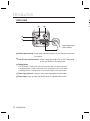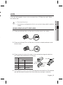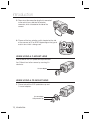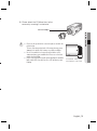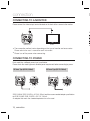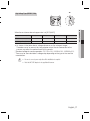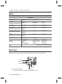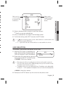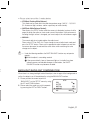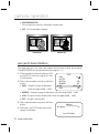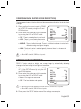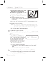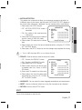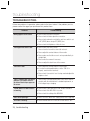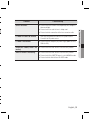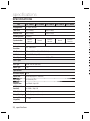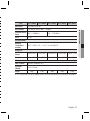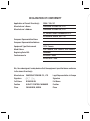
1
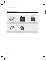
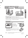
Low Light, High Resolution, Day & Night Camera User Manual SCB-1000 B T ■ ■ Low Light, High Resolution, Day & Night Camera User Manual Copyright ©2010 Samsung Techwin Co., Ltd. All rights reserved. Trademark is the registered logo of Samsung Techwin Co., Ltd. The name of this product is the registered trademark of Samsung Techwin Co., Ltd. Other trademarks mentioned in this manual are the registered trademark of their respective company. Restriction Samsung Techwin Co., Ltd shall reserve the copyright of this document. Under no circumstances, this document shall be reproduced, distributed or changed, partially or wholly, without formal authorization of Samsung Techwin. Disclaimer Samsung Techwin makes the best to verify the integrity and correctness of the contents in this document, but no formal guarantee shall be provided. Use of this document and the subsequent results shall be entirely on the user’s own responsibility. Samsung Techwin reserves the right to change the contents of this document without prior notice. Warranty If the product does not operate properly in normal conditions, please let us know. Samsung Techwin will resolve the problem for free of charge. The warranty period is 3 years. However, the followings are excluded: • If the system behaves abnormally because you run a program irrelevant to the system operation. • Deteriorated performance or natural worn-out in process of time Before operating the camera, confirm the camera model and correct input power voltage. To help you understand this manual thoroughly, we’ll introduce our model description. ■ SCB-1000 SERIES • NTSC MODEL SCB-1000ND SCB-1000NA • PAL MODEL SCB-1000PD SCB-1000PA SCB-1000PH ■ MODEL DESCRIPTION • SCB-1000X_ _X POWER SOURCE SIGNAL SYSTEM • SIGNAL SYSTEM N → NTSC MODEL P → PAL MODEL • POWER SOURCE D → DC 12V A → AC 24V~ H → AC 230V~ safety information 6 CAUTION RISK OF ELECTRIC SHOCK. DO NOT OPEN CAUTION: TO REDUCE THE RISK OF ELECTRIC SHOCK, DO NOT REMOVE COVER (OR BACK) NO USER SERVICEABLE PARTS INSIDE. REFER SERVICING TO QUALIFIED SERVICE PERSONNEL. This symbol indicates that dangerous voltage consisting a risk of electric shock is present within this unit. This exclamation point symbol is intended to alert the user to the presence of important operating and maintenance (servicing) instructions in the literature accompanying the appliance. 7 8 9 1 C WARNING • To prevent damage which may result in fire or electric shock hazard, do not expose this appliance to rain or moisture. • To prevent injury, this apparatus must be securely attached to the floor/wall in accordance with the installation instructions. 1 2 3 WARNING 1. Be sure to use only the standard adapter that is specified in the specification sheet. Using any other adapter could cause fire, electrical shock, or damage to the product. 2. Incorrectly connecting the power supply or replacing battery may cause explosion, fire, electric shock, or damage to the product. 4 5 6 3. Do not connect multiple cameras to a single adapter. Exceeding the capacity may cause abnormal heat generation or fire. 7 4. Securely plug the power cord into the power receptacle. insecure connection may cause fire. 8 5. When installing the camera, fasten it securely and firmly. The fall of camera may cause personal injury. 9 4_ safety information 1 e e 7. Do not install the unit in humid, dusty, or sooty locations. doing so may cause fire or electric shock. 8. If any unusual smells or smoke come from the unit, stop using the product. in such case, immediately disconnect the power source and contact the service center. continued use in such a condition may cause fire or electric shock. 9. If this product fails to operate normally, contact the nearest service center. never disassemble or modify this product in any way. (samsung is not liable for problems caused by unauthorized modifications or attempted repair.) 10. When cleaning, do not spray water directly onto parts of the product. doing so may cause fire or electric shock. CAUTION 1. Do not drop objects on the product or apply strong shock to it. Keep away from a location subject to excessive vibrationor magnetic interference. 2. Do not install in a location subject to high temperature (over 50°C), low temperature (below -10°C), or high humidity. Doing so may cause fire or electric shock. 3. If you want to relocate the already installed product, be sure to turn off the power and then move or reinstall it. 4. Remove the power plug from the outlet when then there is a lightning. Neglecting to do so may cause fire or damage to the product. 5. Keep out of direct sunlight and heat radiation sources. It may cause fire. 6. Install it in a place with good ventilation. 7. Avoid aiming the camera directly towards extremely bright objects such as sun, as this may damage the CCD image sensor. 8. Apparatus shall not be exposed to dripping or splashing and no objects filled with liquids, such as vases, shall be placed on the apparatus. 9. The Mains plug is used as a disconnect device and shall stay readily operable at any time. 10. Do not expose the camera to radioactivity. Radioactivity exposure may damage the CCD. English_5 ● SAFETY INFORMATION c 6. Do not place conductive objects (e.g. screwdrivers, coins, metal parts, etc.) or containers filled with water on top of the camera. doing so may cause personal injury due to fire, electric shock, or falling objects. safety information im FCC STATEMENT 1 This device complies with part 15 of the FCC Rules. Operation is subject to the following two conditions : 2 1) This device may not cause harmful interference, and 2) This device must accept any interference received including interference that may cause undesired operation. CAUTION This equipment has been tested and found to comply with the limits for a Class A digital device, pursuant to part 15 of FCC Rules. These limits are designed to provide reasonable protection against harmful interference when the equipment is operated in a commercial environment. This equipment generates, uses, and can radiate radio frequency energy and, if not installed and used in accordance with the instruction manual, may cause harmful interference to radio communications. Operation of this equipment in a residential area is likely to cause harmful interference in which case the user will be required to correct the interference at his own expense. 3 4 5 6 7 8 9 IC Compliance Notice This Class A digital apparatus meets all requirements of the Canadian Interference.-Causing Equipment Regulations of ICES-003. 1 1 Correct Disposal of This Product (Waste Electrical & Electronic Equipment) 1 (Applicable in the European Union and other European countries with separate collection systems) This marking on the product, accessories or literature indicates that the product and its electronic accessories (e.g. charger, headset, USB cable) should not be disposed of with other household waste at the end of their working life. To prevent possible harm to the environment or human health from uncontrolled waste disposal, please separate these items from other types of waste and recycle them responsibly to promote the sustainable reuse of material resources. Household users should contact either the retailer where they purchased this product, or their local government office, for details of where and how they can take these items for environmentally safe recycling. Business users should contact their supplier and check the terms and conditions of the purchase contract. This product and its electronic accessories should not be mixed with other commercial wastes for disposal. Correct disposal of batteries in this product (Applicable in the European Union and other European countries with separate battery return systems.) This marking on the battery, manual or packaging indicates that the batteries in this product should not be disposed of with other household waste at the end of their working life. Where marked, the chemical symbols Hg, Cd or Pb indicate that the battery contains mercury, cadmium or lead above the reference levels in EC Directive 2006/66. If batteries are not properly disposed of, these substances can cause harm to human health or the environment. To protect natural resources and to promote material reuse, please separate batteries from other types of waste and recycle them through your local, free battery return system. 6_ safety information 1 1 o e t 1. Read these instructions. 2. Keep these instructions. 3. Heed all warnings. 4. Follow all instructions. 5. Do not use this apparatus near water. 6. Clean only with dry cloth. 7. Do not block any ventilation openings. Install in accordance with the manufacturer’s instructions. 8. Do not install near any heat sources such as radiators, heat registers, or other apparatus (including amplifiers) that produce heat. 9. Do not defeat the safety purpose of the polarized or grounding-type plug. A polarized plug has two blades with one wider than the other. A grounding type plug has two blades and a third grounding prong. The wide blade or the third prong is provided for your safety. If the provided plug does not fit into your outlet, consult an electrician for replacement of the obsolete outlet. 10. Protect the power cord from being walked on or pinched particularly at plugs, convenience receptacles, and the point where they exit from the apparatus. 11. Only use attachments/accessories specified by the manufacturer. 12. Use only with cart, stand, tripod, bracket, or table specified by the manufacturer, or sold with the apparatus. 13. Unplug this apparatus when a card is used. Use caution when moving the cart/ apparatus combination to avoid injury from tip-over. 14. Refer all servicing to qualified service personnel. Servicing is required when the apparatus has been damaged in any way, such as powersupply cord or plug is damaged, liquid has been spilled or objects have fallen into the apparatus, the apparatus has been exposed to rain or moisture, does not operate normally, or has been dropped. Apparatus shall not be exposed to dripping or splashing and no objects filled with liquids, such as vases, shall be placed on the apparatus e English_7 ● SAFETY INFORMATION e important safety instructions contents i INTRODUCTION 9 CONNECTION 16 CAMERA OPERATION 18 TROUBLESHOOTING 9 10 11 13 Features What’s included Component names and functions Lens 16 16 Connecting to a monitor Connecting to power 18 18 Menu Settings F y y y y 28 Troubleshooting y 28 y SPECIFICATIONS 30 30 Specifications y y y 8_ contents s introduction FEATURES y Electronic DAY & NIGHT This camera has a function that electronically selects the mode that is appropriate for daytime or night-time conditions. The COLOR mode operates in daytime conditions to provide optimum colors, and BW mode operates in night-time conditions to enhance the definition of the image. y Electronic IRIS The electronic IRIS function enables continuous automatic control of the shutter between 1/60(1/50)~1/120,000 seconds. y PRIVACY Function The PRIVACY function conceals the areas you do not wish to appear on the screen. y VIDEO/DC Drive Lens The video drive lens and the DC drive lens can be selected by the touch of a switch. y High Sensitivity The built-in high sensitivity COLOR CCD enables a clear image even in 0.3lux or lower illumination. y SSNR (Samsung Super Noise Reduction) By using built-in SSNR function manufactured by SAMSUNG TECHWIN, the amount of low illuminance noise has been significantly reduced, and the signal-to-noise ratio (S/N) as well as horizontal resolution have been improved, resulting in a clear and sharp image display even in the dark. y Controlled by OSD Menu The camera can be controlled by selecting text displayed on the monitor screen. - ENGLISH, PORTUGUESE y Additional Functions SENS-UP, MOTION DETECTION, MIRROR, SHARPNESS and SYNC(INT/LL) functions are also available. English_9 ● INTRODUCTION y Horizontal Resolution 540 TV Lines Clear image quality has been achieved by employing a CCD with 410,000 pixels (NTSC), 470,000 pixels (PAL), which provides a horizontal resolution of 540 TV lines. introduction C WHAT’S INCLUDED F Check if the following items are included in the product package. Low Light, High Resolution, Day & Night Camera Low Light, High Resolution, Day & Night Camera User Manual SCB-1000 SCB-1000 User Manual Auto iris lens connection plug C-Mount adaptor 10_ introduction Quick Set-up Guide SCB-1000 Quick Set-up Guide COMPONENT NAMES AND FUNCTIONS FRONT VIEW ➊ SIDE VIEW ➋➌ ➍ ➍ ● INTRODUCTION ❶ CCD protection cap : Please cover the CCD SENSOR when not using it. ❷ C-Mount lens adaptor : Please attach the C-Mount lens here. ❸ CS-Mount lens adaptor : Please remove the C-MOUNT lens adaptor and then attach it. ❹ Back Focus clamp screw : Please loosen the clamp screw with a screwdriver before adjusting the Back Focal length. ❺ Auto iris lens connector BOTTOM VIEW ❻ Mounting bracket screw hole ➏ Please use the screw hole when fixing the camera onto the mounting bracket. Please use the 1/4”-20 UNC (20 THREAD) L:4.5mm±0.2mm (ISO standard), clamp screw as specified or 0.197” (ASA standard) below. L ※ The mounting bracket can be separated and attached to the top of the camera. In this instance please do not tighten the screw to a depth of more than 4mm, otherwise serious damage can occur to the inside of the camera. This camera package does not include the mounting bracket. Please refer to the user’s manual for installation of the mounting bracket. English_11 introduction L REAR VIEW ➑ L le ➐ ⓫ ➒ ❿ * High Voltage Type (SCB-1000PH) ➐ Video output terminal : Sends video signal and connects to the video input terminal of the monitor. ➑ Auto iris lens selection switch : Please change the mode to DC or VIDEO depending on the type of auto iris lens being used. ➒ Setting button: • SETUP button : Displays the menu on the screen and uses enter sub menu. • Up&Down button : Used to move the cursor up or down in the menu screen. • Left&Right button :Used to move the cursor left or right in the menu screen. ❿ Power input terminal : Connects to the power appropriate to each model. ⓫ Power lamp : Lights up when the correct power is supplied to the camera. 12_ introduction Lenses are sold separately. Lenses such as an auto iris lens, CS-Mount lens and C-Mount lens can be used. Please keep the lens clean. Any foreign objects and fingermarks on the lens can cause inferior image quality in low light level conditions. WHEN USING AN AUTO IRIS LENS 1. Please peel off about 8mm of the outer skin of the auto iris lens cable. approx. 8mm f 2. Please peel off about 2mm of the outer skin of the insulated conductor inside the lens cable. approx. 2mm 3. Please remove the cover of the auto iris lens connection plug and solder the lens cable to the connector pin in the plug. LENS Pin No. DC VIDEO No.1 Pin Damping - Red (power) No.2 Pin Damping + NC No.3 Pin Drive + White (video signal) No.4 Pin Drive - Black (GND) Lens cable No.3 Pin No.1 Pin Connector No.4 Pin No.2 Pin 4. Please replace the auto iris lens connection plug cover and take off the CCD protection cap, and then attach the auto iris lens to the camera by screwing it in clockwise. English_13 ● INTRODUCTION e LENS introduction 5. Please insert the connection plug that is connected to the auto iris lens cable into the auto lens connector, which is located on the side of the camera. 6. Please set the lens selection switch, located on the side of the camera, to DC or VIDEO depending on the type of auto iris lens which is being used. WHEN USING A C-MOUNT LENS Please take off the CCD protection cap and attach the C-Mount lens to the camera by screwing it in clockwise. C-mount adaptor WHEN USING A CS-MOUNT LENS 1. Please take off the CCD protection cap and C-mount adaptor. C-mount adaptor CCD protection cap 14_ introduction 2. Please attach the CS-Mount lens to the camera by screwing it in clockwise. CS-mount adaptor ● INTRODUCTION Please use the specified lens connection parts as shown in the picture below. The use of the wrong sized parts of the wrong size may cause damage to the inside of the camera or result in poor fitting. Use of a lens which is too heavy affects the balance of the camera and may cause a malfunction. Please use a lens that weighs less than 450g. Please select Av mode if possible when adjusting the automatic light control (ALC) of an auto lens. Use of PK mode may cause hunting. C-mount lens : 10 mm or less CS-mount lens : 5 mm or less English_15 connection CONNECTING TO A MONITOR Please connect the video output terminal located on the back of the camera to the monitor. W C CCD Camera Monitor y The connection method varies depending on the type of monitor and accessories. Please refer to the user’s manual for each instrument. y Please turn off the power when connecting. CONNECTING TO POWER Each model has a different power input specification. Please check the model type and standard power requirement before connecting to power. AC Power Type (AC 24V, 300mA) DC Power Type (DC 12V, 500mA) SCB-1000NA/ SCB-1000PA is AC 24V, 300mA and the recommended adaptor specification for SCB-1000ND/ SCB-1000PD is DC 12V, 500mA. An adaptor that meets the standard requirement must be used. 16_ connection y * * High Voltage Type (AC230V, 50Hz) Copper wire size (AWG) #24 (0.22mm2) #22 (0.33mm2) #20 (0.52mm2) #18 (0.83mm2) Resistance value(/m) 0.078 0.050 0.030 0.018 Voltage Drop (V/m) 0.028 0.018 0.011 0.006 y As shown in the table above, voltage decreases as the wire gets longer. Therefore use of an excessively long adaptor output line for connection to the camera may affect the performance of the camera. * Standard voltage for camera operation : DC 12V ±10%, AC24V±10%, AC230V±10% * There may be some deviation in voltage drop depending on the type of wire and the manufacturer. Be sure to connect power only after all the installation is complete. Note that AC / DC adaptor is not supplied with camera. n English_17 ● CONNECTION When the resistance value of copper wire is at [20°C(68°F)] camera operation MENU Setup Menu LENS (selection) ● MANUAL ● DC / VIDEO SHUTTER (condition and speed control) ● ESC ● MANUAL ● FLK WHITE BAL ● ATW ● AWC ● MANUAL BACKLIGHT (Backlight compensation) ● OFF ● HIGH ● LOW ● MIDDLE AGC (Auto Gain control) ● OFF ● HIGH ● LOW ● MIDDLE SSNR (Samsung super noise reduction) ● OFF ● HIGH ● LOW ● MIDDLE SENS-UP (Low illuminance) ● OFF ● AUTO SPECIAL ● IMAGE ADJ ● SYNC ● LANGUAGE ● CAMERA ID ● MOTION DET ● RESET ● COLOR ● PRIVACY ● RETURN EXIT SETTINGS Settings can be made using the 5 buttons located on the back of the camera. UP button LEFT button SET button RIGHT button 1. Press the SET button DOWN button y Main setup menu is displayed on the monitor screen. 18_ camera operation SETUP Select any function you wish to operate by using the UP and DOWN buttons. DC Modes can be changed using the LEFT and RIGHT buttons. --ATW OFF MIDDLE LOW OFF ● CAMERA OPERATION 䯝 LENS SHUTTER WHITE BAL. BACKLIGHT AGC SSNR SENS-UP SPECIAL EXIT 2. Select a desired function using the Up and Down buttons. y Place the cursor over a desired item. 3. Set up a selected item by using the Left and Right buttons. 4. To finish the setting, select ‘EXIT’ and press the SET button. If appears at the mode you wish to operate, it means that there is a sub-menu which can be selected by pressing the SETUP button. If - - - appears at the mode item, it means that there is no mode available to be selected. LENS (SELECTION) This function is used to adjust the brightness of the screen. 1. When the SETUP menu is displayed on the screen, please position the arrow to point to ‘LENS’ by using the UP and DOWN buttons. SETUP 䯝 LENS SHUTTER DC --- 2. Please select the type of the lens you wish to use by pressing the LEFT or RIGHT button. y DC/VIDEO : Auto iris lens selection When using an auto iris lens, the setting of the auto iris lens selection switch, located on the back of the camera, must be on DC or VIDEO depending on the type of the lens which is being used. (Please refer to the picture on page 13) The brightness of the screen can be adjusted in DC mode. The brightness can be adjusted within the range of 1 ~ 70. The optimum level of brightness for the user can be achieved by adjustment. y MANUAL : Manual lens selection 3. Please press the SETUP button if you wish to return to the previous menu. English_19 camera operation SHUTTER (CONDITION AND SPEED CONTROL) Auto or manual control can be selected. 1. When the SETUP menu is on the screen, please position the arrow to point to ‘SHUTTER’ by using the DOWN button. 2. Please select the shutter mode by pressing the LEFT or RIGHT button. SETUP LENS 䯝 SHUTTER WHITE BAL. DC --ATW y FLK : Please select ‘FLK’ mode when flickering occurs on the screen, due to an imbalance between illumination and frequency. NTSC Model: 1/100sec, PAL MODEL: 1/120sec y ESC : Auto control of the shutter speed can be achieved. When ESC mode is on, the speed is controlled automatically according to the brightness of the screen. y MANUAL : The shutter speed can be controlled manually. 3. Please select ‘MANUAL’ mode if you wish to adjust the shutter manually. y You can select speed from ‘1/60’ to ‘1/120,000’sec (NTSC Models), ‘1/50’ to ‘1/120,000’ sec (PAL Models). 4. Please press the SETUP button when all the settings are complete. When selecting DC/VIDEO lens, the shutter speed is fixed at 1/60 (1/50) sec. While using the internal synchronous system, if the shutter setting is on ‘ESC’ and the camera is directly facing a bright fluorescent light, the image on the screen can be adversely affected. Therefore please choose the installation location with care. When the SHUTTER is set to MANUAL or A.FLK mode, SENS-UP will be disabled. WHITE BAL (WHITE BALANCE) The screen color can be adjusted by using the WHITE BALANCE function. 1. Please position the arrow to point to ‘WHITE BAL’ on the SETUP menu by using the UP and DOWN buttons. 2. Please select the mode you wish to operate by pressing the LEFT or RIGHT button. 20_ camera operation SETUP LENS SHUTTER 䯝 WHITE BAL. BACKLIGHT DC --ATW OFF is d. y ATW(Auto Tracking White Balance) : This mode can be used within the color temperature range 1,800°K ~ 10,500°K (Ex. fluorescent light, outdoor, sodium vapor lamp or inside tunnels) y AWC(Auto White Balance Control) : Please press the SETUP button while the camera is directed at a piece of white paper to obtain the optimum state under current illumination. If the environment including the light source is changed, you have to adjust the white balance again. y MANUAL : The manual adjustment mode enables finer adjustment. Please select ATW or AWC first. Please change to manual adjustment mode and press the SETUP button. Please set the appropriate color temperature, and then increase or decrease the red and blue color values while monitoring the color changes on the object. Under the following conditions the WHITE BALANCE function may not operate properly. ➊ When the object´s surroundings are dark ➋ If the camera directly faces a fluorescent light or is installed in a place where there are considerable changes in illumination, the WHITE BALANCE function may become unstable. BACKLIGHT (BACKLIGHT COMPENSATION) When there is a strong backlight behind the object, clear images of the background as well as the object can still be obtained by using the BACKLIGHT function. 1. Please position the arrow to point to ‘BACKLIGHT’ on the SETUP menu by using the UP and DOWN buttons. 2. Please select the mode you wish to operate by pressing the LEFT or RIGHT button. SETUP LENS SHUTTER WHITE BAL. 䯝 BACKLIGHT AGC DC --ATW OFF MIDDLE English_21 ● CAMERA OPERATION e ※ Please select one of the 3 modes below. camera operation y HIGH/MIDDLE/LOW : You can adjust the sensitivity of Backlight Compensation. y OFF : BLC function doesn´t operate. BACKLIGHT ON BACKLIGHT OFF AGC (AUTO GAIN CONTROL) The higher gain level, the screen gets brighter and the level of noise also increases. The BRIGHTNESS can be adjusted within the range of 1~70. 1. Please position the arrow to point to ‘AGC’ on the SETUP menu by using the UP and DOWN buttons. 2. Select a desired mode using the Up and Down buttons. y HIGH : The gain increases or decreases within the range of 6dB ~ 34dB. SETUP LENS SHUTTER WHITE BAL. BACKLIGHT 䯝 AGC SSNR DC --ATW OFF MIDDLE LOW y MIDDLE : The gain increases or decreases within the range of 6dB ~ 30dB. y LOW : The gain increases or decreases within the range of 6dB ~ 18dB. y OFF : The gain is fixed at 6dB. 3. Select a desired mode using the Up and Down buttons. 4. Please press the SETUP button when all the settings are complete. Brightness 䯝 Brightness IIIIIIIIIIIIIIIIIIIIIIIIIIIIIIII 25 Press SET to Return 22_ camera operation The background noise in the low light level decreases automatically as the level of gain changes. 1. Please position the arrow to point to ‘SSNR’ on the SETUP menu by using the UP and DOWN buttons. 2. Please select the mode you wish to operate by pressing the LEFT or RIGHT button. y OFF : There is no reduction in noise level. y LOW : There is a small reduction in noise level with almost no ghost image. SETUP LENS SHUTTER WHITE BAL. BACKLIGHT AGC 䯝 SSNR SENS-UP DC --ATW OFF MIDDLE LOW OFF y MIDDLE : The most effective mode. There is a sufficient reduction in noise levels without causing much ghost imaging. y HIGH : The level of noise is reduced greatly, however there is an increase in ghost imaging. When AGC is turned off, SSNR does not operate. SENS UP (LOW ILLUMINANCE) SENS UP helps maintain a bright, clear screen image by automatically detecting changes in the level of light in low light level conditions. 1. Please position the arrow to point to ‘SENS UP’ on the SETUP menu by using the UP and DOWN buttons. 2. Please select the mode you wish to operate by pressing the LEFT or RIGHT button. y AUTO : Low light level auto mode y OFF : The function does not operate. SETUP LENS SHUTTER WHITE BAL. BACKLIGHT AGC SSNR 䯝 SENS-UP SPECIAL DC --ATW OFF MIDDLE LOW OFF When SHUTTER is in the manual mode and the FLK mode. SENS UP does not operate. When AGC is turned off, SENS UP does not operate. 3. Please press the SETUP button when all the settings are complete. English_23 ● CAMERA OPERATION s. SSNR (SAMSUNG SUPER NOISE REDUCTION) camera operation The maximum storage magnification in low light level can be adjusted by pressing the SETUP button in ‘AUTO’ mode.(X2~X128) As the magnification increases, the screen gets brighter; moving object gets more afterimage. If storage magnification is increased while SENS UP is operating, it may cause noise, and spots may appear; however this is normal. SPECIAL 1. Please position the arrow to point to ‘SPECIAL’ on the SETUP menu by using the UP and DOWN buttons. 2. Please select the mode you wish to operate by pressing the UP or DOWN button. y IMAGE ADJ : 1) When the SPECIAL menu screen is displayed, select ‘IMAGE ADJ’ by Using the Up and Down buttons so that the arrow indicates ‘IMAGE ADJ’. 2) Select a desired mode using the Up and Down buttons. MIRROR: - ON : Sets a horizontal image inversion. SPECIAL 䯝 IMAGE ADJ CAMERA ID COLOR SYNC MOTION DET PRIVACY LANGUAGE RESET RETURN OFF ON INT OFF OFF ENGLISH IMAGE ADJ 䯝 MIRROR SHARPNESS RETURN OFF ON - OFF : Cancels the inversion. MIRROR ON 24_ camera operation MIRROR OFF g e SHARPNESS Level IIIIIIIIIIIIIIIIIIIIIIIIIIIIIIII 8 Press SET to Return - Please press the SETUP button. - The available range of level is 0 ~ 31. y CAMERA ID : 1) Please position the arrow to point to ‘CAMERA ID’ by using the UP or DOWN button. 2) Please select ‘ON’ by pressing the LEFT or RIGHT button. If ‘OFF’ is selected, the ID does not appear on the monitor even if it has been input. 3) Please press the SETUP button. 4) Up to 15 letters can be used for the ID. ➊ Please move the cursor to the letter you wish to choose by using the UP and DOWN button. ➋ Select an ID from A,B~Y,Z, a,b~y,z, 0,1~8,9 by using the UP, DOWN, LEFT and RIGHT buttons. ➌ Please lock in the letters by using the SETUP button. - When the letter is locked in, the cursor moves to the next space. CAMERA ID A B C N O P a b c n o p - . 0 ←→ D E Q R d e q r 1 2 CL F G H I J K L M S T U V W X Y Z f g h i j k l m s t u v w x y z 3 4 5 6 7 8 9 R POS END _______________ ➍ Please repeat the above to input the ID. If the wrong name has been input..... If you press the SETUP button after moving the cursor to CLR, all the letters will be erased. If you want to correct a letter, please move the cursor to the arrow at the bottom left of the screen and press ‘SET’. Please position the cursor above the letter you wish to correct, and then move the cursor onto the letter you wish to choose and press the SETUP button. English_25 ● CAMERA OPERATION e SHARPNESS : The outline of the video image becomes cleaner and more distinctive as the level of SHARPNESS increases. If the level goes up excessively, however, it may affect the video image and generate noise. camera operation 5) When a name has been chosen, please select a position for the name display. FRONT DOOR ➊ Please move the cursor onto ‘POS’ and then press the SETUP button. ➋ The name will appear at the top left hand corner. ➌ Please find the position you wish to display the name by using the 4 directional buttons, and then press the SETUP button. 6) Please select ‘END’ and then press the SETUP button to complete ID input. y COLOR (Electronic DAY & NIGHT) : - AUTO : This camera has a function which electronically changes to the appropriate mode for daytime or night-time. The COLOR mode is operated for daytime, and it converts to BW mode for night-time. - ON : The color mode is selected electronically. If AGC is OFF, you can´t select AUTO mode. When an infrared light is used, there may be a problem with focusing and COLOR (DAY & NIGHT). y SYNC : Two SYNCHRONIZATION modes are SYNC available INTERNAL and EXTERNAL LINEIIIIIIIIIIIIIIIIIIIIIIIIIIIIIIII 0 PHASE LOCK. In LINE-LOCK mode, it synchronizes the video signal between cameras without a synchronous generator. The line-lock synchronization is only used in the areas of 60Hz (NTSC Models) / 50Hz (PAL Models). - INT : Internal synchronization - LL : External line-lock synchronization y If you choose ‘LL’, you can adjust the desired phase. Press the SET button. y You can adjust the desired phase from 0 to 359. When the power frequency is 50Hz, you can not use line-lock mode (NTSC Models). When the power frequency is 60Hz, you can not use the line-lock mode (PAL Models). ‘Sync.’ mode is fixed to ‘INT’ in DC 12V input power. 26_ camera operation MOTION DETECT - OFF : MOTION DETECTION mode is ▶ AREA SEL AREA1 AREA STATE ON cancelled. IIIIIIIIIIIIIIIIIIIIIIIIIIIIIIII 15 TOP - ON : Any motion in the selected areas IIIIIIIIIIIIIIIIIIIIIIIIIIIIIIII 30 DOWN is observed. IIIIIIIIIIIIIIIIIIIIIIIIIIIIIIII 20 LEFT 2) Please select the area you wish to observe IIIIIIIIIIIIIIIIIIIIIIIIIIIIIIII 40 RIGHT from the 4 areas in AREA SEL mode. Press SET to Return 3) Please select ON mode for the chosen area. 4) Please adjust the size of the area to be observed by using the UP, DOWN, LEFT or RIGHT button. 5) Please press the SETUP button to save the changes and complete the setting. There is no MD output signal. MD is on screen display only words. y PRIVACY : Hide an area you want to hire on the screen. - OFF : Cancels the PRIVACY mode. - ON : Operates the PRIVACY mode. 1) Please press the SETUP button. 2) Please select the area you do not wish to appear from the 4 areas in AREA SEL mode. 3) Please select ON mode for the chosen area. 4) Please adjust the size of the area to be concealed by using the UP, DOWN, LEFT or RIGHT button. PRIVACY ▶ AREA SEL AREA1 AREA STATE ON AREA TONE IIIIIIIIIIIIIIIIIIIIIIIIIIIIIIII 15 IIIIIIIIIIIIIIIIIIIIIIIIIIIIII I I 30 TOP IIIIIIIIIIIIIIIIIIIIIIIIIIIIIIII 29 DOWN IIIIIIIIIIIIIIIIIIIIIIIIIIIIII I I LEFT 20 IIIIIIIIIIIIIIIIIIIIIIIIIIIIIIII 40 RIGHT Press SET to Return y LANGUAGE : You can select the menu language according to your requirements. y RESET : Returns to the level which was set by the manufacturer for shipment. y RETURN : Returns to the SETUP menu. EXIT Saves all the setting menus and then exits. English_27 ● CAMERA OPERATION ). y MOTION DETECTION : This product has a feature that allows you to observe movements of objects in 4 different areas on the screen, and the words ‘MOTION DETECTED’ appear on the screen when movement is detected; You can monitor activity more efficient. 1) Please press the SETUP button. troubleshooting TROUBLESHOOTING If there are problems in operation, please refer to the items below. If the problem persists, please contact the agent you purchased this product from. Problems Troubleshooting Nothing appears on the screen. y Please check the power connection. y Please check the video signal line connection. y Please check and make sure that the auto lens switch is set to DC (VIDEO) when using a DC (VIDEO) lens. y Please check the Brightness of Auto Iris lens. The image on the screen is dim. y Please check if the lens is clean. Please clean the lens with a clean cloth or brush. y Please adjust the contrast feature of the monitor. y Please make sure that the screen is not exposed directly to a bright light. y Please move the camera if necessary. y Please readjust the back focus of the camera. The screen is dark. y Please adjust the contrast feature of the monitor. y If you have an intermediate device, set the 75Ω / Hi-z properly, and check the terminals. y Please check if an auto iris lens is being used and adjust the brightness level. There is a problem with the camera operation. The camera surface is too hot and black stripes appear on the screen. y Please check if an appropriate power source to the camera complies with the manufacturer’s standard requirement, or if the voltage keeps changing. The MOTION DETECTION function is not working. y Please check if ‘MOTION DETECTION’ mode is turned on. y Please check if the MD LEVEL is too low. y Please check the setting of the MD AREA. Colors are not quite right. y Please check the ‘WHITE BAL’ setting. (Please refer to page 20) The screen is flickering. y Check that MOTION DEF of SPECIAL SETUP menu is ‘OFF’. 28_ troubleshooting Problems Troubleshooting y Please check if the camera is facing directly into sunlight or fluorescent light. y Please check if an auto iris lens is being used. y Please check the connection of the lens connector cable. L/L mode isn’t able to be selected. y Have you connected your camera to DC power source? Connect it to AC power source. L/L mode is not available. y Please check the frequency of power supply (60Hz for NTSC, 50Hz for PAL). COLOR (DAY & NIGHT) mode is not working. y Please check if the AGC menu is set to the OFF position. SENS-UP function is not working. y Please check if the AGC menu is set to the OFF position. y Please check if the SHUTTER menu is set to MANUAL mode. y Please check the limit of Sens-UP AUTO mode. English_29 ● TROUBLESHOOTING Color is not correct. specifications SPECIFICATIONS Item SCB-1000NA SCB-1000ND SCB-1000PA SCB-1000PD SCB-1000PH G Imaging Device 1/3” Super HAD CCD Total Pixels 811(H) x 508(V) 795(H) x 596(V) Effective Pixels 768(H) x 494(V) 752(H) x 582(V) W E S Scanning System 2:1 Interlace Internal / Line lock Synchronization M Internal Internal / Line lock Frequency H:15.734KHz / V:59.94Hz Horizontal Resolution Color : 540 TV lines Min. Illumination 0.05Lux / 0.0004Lux (F1.2, SENS-UP x128) S / N Ratio 50dB(AGC OFF, Weight ON) Internal H : 15.625KHz / V : 50Hz Internal / Line lock E O T H E 1.0Vp-p/75Ω Video Output I C P M Lens Type Lens Type Manual / Auto Iris (Video/DC) C Mount Type C / CS D ( Operational On Screen Display Built-in Camera Title Off / On (Displayed 15 characters) Day & Night Auto (Electrical) / On Backlight Compensation Low / Middle / High / Off SSNR(Digital Noise Low / Middle / High / Off Reduction) Motion Detection Off / On (4 programmable zones) Privacy Masking Off / On (4 programmable zones) Sens-up (Frame Integration) 2x ~ 128x 30_ specifications W ※ Item SCB-1000NA SCB-1000ND SCB-1000PA Low / Middle / High / Off White Balance ATW / Manual / AWC (1,800K° ~ 10,500K°) Electronic Shutter 1/60 ~ 1/120,000 sec Speed Mirror SCB-1000PD SCB-1000PH ● SPECIFICATIONS Gain Control 1/50 ~ 1/120,000 sec Off / On Environmental Operating Temperature / Humidity -10°C ~ +50°C (+14°F ~ +122°F) / Less than 90% RH Electrical Input Voltage/ Current 24VAC±10% 12VDC±10% 24VAC±10% Power Source Max. 3.5W Max. 2.5W Max. 3.5W Max. 2.5W Max. 4.0W 340g 310g 510g 12VDC±10% 230V AC ± 10% Mechanical Color / Material Light Silver / Aluminum, Steel Dimension (WxHxD) 58 x 52 x 121mm Weight 340g 310g ※ This specification can be changed without notice for performance improvement of product. English_31 DECLARATION OF CONFORMITY Application of Council Directive(s) 2004 / 108 / EC Manufacturer's Name SAMSUNG TECHWIN CO., LTD Manufacturer's Address SAMSUNG TECHWIN CO., LTD 42, SUNGJU-DONG CHANGWON-CITY, KYUNGNAM, KOREA, 641-716 European Representative Name European Representative Address Equipment Type/Environment CCTV Camera Model Name SCB-1000PA, SCB-1000PD, SCB-1000PH, Beginning Serial NO. S8060001 Conformance to EN 55022 : 2006 EN 50130-4 : 2003 We, the undersigned, hereby declare that the equipment specified above conforms to the above Directive(s). Manufacturer SAMSUNG TECHWIN CO., LTD Legal Representative in Europe Signature Signature Full Name BONJENG GU Position QUALITY CONTROL MANAGER Full Name Position Place CHANGWON, KOREA Place MEMO H, ms pe MEMO MEMO MEMO MEMO MEMO MEMO SALES NETWORK SAMSUNG TECHWIN CO., LTD. Samsungtechwin R&D Center, 701, Sampyeong-dong, Bundang-gu, Seongnam-si, Gyeonggi-do, Korea, 463-400 TEL : +82-70-7147-8740~60, FAX : +82-31-8018-3745 SAMSUNG TECHWIN AMERICA Inc. 1480 Charles Willard St, Carson, CA 90746, UNITED STATES Tol Free : +1-877-213-1222, FAX : +1-310-632-2195 www.samsungcctvusa.com www.samsungtechwin.com www.samsungsecurity.com SAMSUNG TECHWIN EUROPE LTD. Samsung House, 1000 Hillswood Drive, Hillswood Business Park Chertsey, Surrey, UNITED KINGDOM KT16 OPS TEL : +44-1932-45-5300, FAX : +44-1932-45-5325 P/NO. : Z6806155701A