1
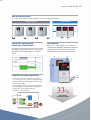
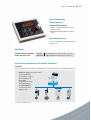
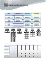
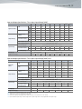
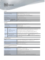
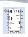
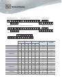
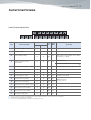
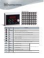
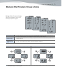
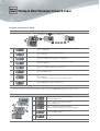
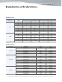
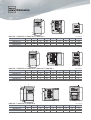
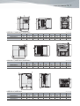
LSLV
Compact Drive
C100
0.1~2.2kW 1phase 200V
0.1~3.7kW 3phase 200V
0.4~7.5kW 3phase 400V
C O N T E N T S
Compact
Convenient
Model & Type / Basic Specifications
Control
Connection Diagram
Terminal Function
Control Circuit Terminal
Keypad Usage & Function
Moving to Other Parameter Groups & Codes
Braking Resistors and Peripheral Devices
Dimensions
04
06
08
10
11
12
13
14
15
17
18
Convenient
Compact
Compact Drive LSLV-C100
LSLV-C100 Provides Optimized Solution
to Global Customers
LSLV-C100, the cost effective and easy-to-install,
compact drive will enhance your machine performance
02_03
Features
Size Reduction
Standard 200V 1.5kW
COMPACT
No Need for 'Big Drives'.
Compact but Optimized LSLV-C100
Will do the Job
Compact Drive LSLV-C100
04_05
Side-by-Side Installation
The control can be significantly reduced thanks to C100's 'side-by-side' installation.
iG5A(500mm)
C100(364mm)
30mm
50mm
50mm
50mm
30mm
50mm
KEB for Safe Operating Stop
in the Event of Power Failure
2mm
2mm
Size Reduction
By using the regenerated power from the decelerating
load, KEB function automatically protects machine by
providing safe(controlled) braking in case of power
outage.
Volume size is reduced by up to 33% compared to
existing products (iG5A) by arranging main components
optimally using thermal analysis and 3D design
(Standard 0015C100-1/0022C100-2/0022C100-4)
W
Input Voltage
H
DC-ink Voltage
Operating
Frequency
Output Current
Compliance with Safety Requirements
D
•If a machine needs safe standstill functionality in
case of emergency, the connection of SA, SB, and SC
terminals that is shorted normally will be opened to
block the drive output.
•Easy to comply with safety requirements at system
level by adding safe input functions complying with
EN ISO 13849-1 PLd and EN 61508 SIL2
(EN60204-1, stop category 0)
24V
SC
/SAT
A
SB
Safety Stop
Relay
PWM
/SAT
B
/OC2
Gate
Block
Note) Safety relay not included
145mm
33%
Size Reduction
Standard 200V 1.5kW
CPU
PWM
Fault
SA
100 128
IM
Features
CONVENIENT
Simple Operation and Easy Maintenance
Features Enhance Customers’ Convenience.
Compact Drive LSLV-C100
User Convenience by
Simple Operation
Integrated Potentiometer
•Provides external potentiometer for easier
frequency control
•Addtional 0~5V analog input for freqeuncy
control
Easy Fan Maintenance
User can easily replace a fan without opening
the drive cover
Dual Rating
Designed to Select Between
Heavy and Light Load
Overload
Withstand
•Heavy load operation: 150% of rated current, 60 sec.
•Light load operation: 100% of rated current, 60 sec.
PC-based Easy Maintenance of Drive/Motor Parameters
DriveView
Drive view software allows drive/System monitoring on a PC and easy maintenance of drive/Motor parameters
•Window based graphic user interface (GUI)
•LS-BUS, Modbus-RTU
•Connecting up to 31 drives
•Great reporting function
•Event logging
•Integrated control console
•Offline editing function
•Data upload/download
•4-channel oscilloscope
•Trigger function
Note) Drive View sw available by 2014. Nov
Converter
06_07
Model & Type / Basic Specifications
Power
1Phase 200V
3Phase 200V
3Phase 400V
0.1 kW
LSLV0001C100-1
LSLV0001C100-2
0.2 kW
LSLV0002C100-1
LSLV0002C100-2
0.4 kW
LSLV0004C100-1
LSLV0004C100-2
LSLV0004C100-4
0.8 kW
LSLV0008C100-1
LSLV0008C100-2
LSLV0008C100-4
1.5 kW
LSLV0015C100-1
LSLV0015C100-2
LSLV0015C100-4
2.2 kW
LSLV0022C100-1
LSLV0022C100-2
LSLV0022C100-4
3.7 kW
LSLV0037C100-2
LSLV0037C100-4
5.5 kW
LSLV0055C100-2
LSLV0055C100-4
7.5 kW
LSLV0075C100-2
LSLV0075C100-4
Drives of capacity 0.1~7.5kW with
EMC filter are under development
0.1~2.2kW-1 : release by May. 2015
0.4~7.5kW-4 : release by May. 2015
Input and Output Specifications : Single-phase Input Voltage (200V)
LSLV□□□□C100-1□
Applicable Motor1)
0001
0002
0004
[HP]
1/8
1/4
[kW]
0.1
0.2
Rated Capacity [kVA]
0.3
Rated Current[A]3)
0.8
2)
Output Ratings
0008
0015
0022
1/2
1
2
3
0.4
0.75
1.5
2.2
0.5
1.0
1.9
3.0
4.2
1.4
2.5
5.0
8.0
11
14.1
24
400 [Hz]4)
Max. Output Frequency
Three Phase 200 ~ 240V5)
Max. Output Voltage [V]
Single Phase 200 ~ 240 VAC (-15% ~ +10%)
Rated Voltage [V]
Input Ratings
Rated Current[A]
1.4
2.8
Weight of Drive [kg]
11
50 ~ 60 [Hz] (±5%)
Rated Frequency
Cooling Type
5.5
Natural Cooling
0.55
0.55
Forced Cooling
0.8
1.22
1.42
1.97
Compact Drive LSLV-C100
08_09
Input and Output Specifications : Three-phase Input Voltage (200V)
LSLV□□□□C100-2□
HD
Applicable Motor1)
ND
Rated Capacity
[kVA] 2)
Output Ratings
Rated Current[A] 3)
0001
0002
0004
0008
0015
0022
0037
0055
0075
[HP]
1/8
1/4
1/2
1
2
3
5
7.5
10
[kW]
0.1
0.2
0.4
0.75
1.5
2.2
3.7
5.5
7.5
[HP]
1/4
1/2
1
1.5
3
4
5.4
10
15
[kW]
0.2
0.4
0.75
1.1
2.2
3.0
4.0
7.5
11.0
HD
0.3
0.5
1.0
1.9
3.0
4.2
6.1
9.1
12.2
ND
0.4
0.7
1.3
2.4
3.8
5.2
7.6
12.1
16.3
HD
0.7
1.5
2.0
5.8
7.5
11.0
18.9
22.1
28.6
ND
1.1
1.8
3.1
6.3
10.0
12.0
18.0
30.0
40.0
Max. Output Frequency
400 [Hz]4)
Max. Output Voltage [V]
Three Phase 200 ~ 240V5)
Rated Voltage [V]
Input Ratings
Rated Current[A] 3)
Three Phase 200 ~ 240 VAC (-15% ~ +10% )
HD
0.7
1.5
2.0
5.8
7.5
11.0
18.9
22.1
28.6
ND
1.1
1.9
3.9
7.3
10.8
13.9
24
28.6
41.2
3.3
3.3
Rated Frequency
50 ~ 60 [Hz] (±5%)
Natural Cooling
Cooling Type
0.55
Weight of Drive [kg]
0.55
Forced Cooling
0.8
0.8
1.22
1.42
1.97
Input and Output Specifications : Three-phase Input Voltage (400V) Class
LSLV□□□□C100-4□
HD
Applicable
Motor1)
ND
Rated Capacity
[kVA] 2)
Output Ratings
Input Ratings
Rated Current[A] 3)
0004
0008
0015
0022
0037
0055
0075
[HP]
1/2
1.0
2.0
3.0
5.0
7.5
10.0
[kW]
0.4
0.75
1.5
2.2
3.7
5.5
7.5
[HP]
1
1.5
3
4
5.4
10
15
[kW]
0.75
1.1
2.2
3.0
4.0
7.5
11.0
HD
1.0
1.9
3.0
4.2
6.1
9.1
12.2
ND
1.2
2.4
3.8
5.2
7.6
12.1
16.3
HD
1.25
2.5
4.0
5.5
8.0
12.0
16.0
ND
2.0
3.1
5.1
6.9
10.0
16.0
23.0
Max. Output Frequency
400 [Hz]4)
Max. Output Voltage [V]
Three Phase 380 ~ 480V5)
Rated Voltage [V]
Rated Current[A] 3)
Three Phase 380 ~ 480 VAC (-15% ~ +10%)
HD
1.8
3.2
4.4
6
10.4
11.0
14.4
ND
2.1
4.3
5.9
8.1
14
14.7
21.9
3.3
3.4
Rated Frequency
Cooling Type
Weight of Drive [kg]
50 ~ 60 [Hz] (±5%)
Natural Cooling
0.8
Forced Cooling
0.8
1.22
1.42
Note 1) Indicates the maximum applicable motor capacity when using a 4-pole standard motor of HIGEN.
Note 2) Rated capacity is based on 220V for 200V class and 440V for 400V class.
Note 3) When Carrier frequency setting (H39) is above 6kHz.
Note 4) The max. frequency setting range can be 120Hz when H40 is set to 3(Sensorless vector control)
Note 5) The maximum output voltage cannot be higher than the input voltage and it can be programmable below input voltage.
1.97
Controller
Control
Control Type
V/F control, sensorless vector control
Frequency Precision Setting
Digital command: 0.01Hz
Analog command: 0.06Hz (Max. frequency: 60Hz)
Frequency Precision
Operation by digital command: 0.01% of max. output frequency.
Analog command operation: 0.1% of max. output frequency.
V/F Pattern
Linear, squared, user V/F
Overload Capacity
HD : 150%/ 1min; ND: 110%/ 1min
Manual/Auto torque compensation
Torque Compensation
Dynamic Torque 20%
Braking
Max. Brake Torque
20%1)
Time/%ED
150%2) when using optional DB resistor
Note 1) Average braking torque during Decel to stop a motor.
Note 2) Refer to manual page 13-6 for DB resistor specification.
Operation
Operation Mode
Keypad / Terminal / Communication operation
Frequency Setting
Analog type: 0 ~ 10[V], 0 ~ 20[mA]
Digital type: Keypad
Panel potentiometer
Operational Functions
PID control, Up-Down operation, 3-wiring operation
Optional NPN / PNP
P1 ~ P5
Input
Multi-function Terminals
(5 pcs) P1 ~ P5
Functions: Forward/Reverse operation, emergency stop, fault reset, Jog operation,
multi-step frequency – high, mid and low, multi-step Accel/ Decel- High, Mid, Low,
DC braking at stop, 2nd motor select, Up/Down operation function
(Increase/Decrease of frequency), 3-wire operation, External fault signal input
(contact A/B), General operation switched during PID operation, 2nd Source,
Analog hold, Accel/Decel stop, Up/Down Save Freq, jog forwards/reverse operation.
Less than (N.O., N.C.) AC250V 1A,
Less than DC 30V 1A
Multi-function Relay
Fault output and drive status output
Analog Output
0 ~ 10Vdc (less than 10mA): Choose among Output Freq, Output Current, Output Voltage,
DC link selectable.
Output
Protective Function
Faults
Over voltage, low voltage, over current, short circuit, ground current detection, drive overheat,
motor overheat, input and output phase loss, overload protection, communication error,
loss of frequency command, hardware fault, cool fan trip, brake error.
Alarm
Stall prevention, overload
Momentary Power Loss1)
Below 16 msec: Continuous operation
Above 16 msec: Auto restarting.
Note 1) the rated input voltage is 220V for 200V class, 440V for 400V class, and the rated input is subject to HD.
Structure and Application Environment
Protection Degree
Application Temperature
Opening (IP 20)
HD operation: - 10 ~ 50°C (no freezing)
ND operation: - 10 ~ 40°C (no freezing)
(But as for operation at 50°C, if the drive adopts VT (HD) load,
it is recommended to use the load blow 80%).
Storage Temperature
-20°C ~ 65°C
Application Humidity
Below relative humidity 90% RH (no condensation)
Altitude/Vibration
Below 1000m, 5.9/sec2 (0.6G)
Atmospheric Pressure
70~106 kPa
Installation Environment
There shall not be corrosive air, combustible gas, oil mist, dust and so on.
Compact Drive LSLV-C100
Connection Diagram
10_11
Terminal Function
0.1kW~0.4kW(Single Phase 200V)
0.75kW~1.5kW(Single Phase 200V)
2.2kW(Single Phase 200V)
0.1kW~0.75kW(Three Phase 200V / 400V) 1.5kW~2.2kW(Three Phase 200V / 400V)
3.7kW(Three Phase 200V / 400V)
5.5kW~7.5kW(Three Phase 200V / 400V)
R.S.T Size
U,V,W Size
Ground Size
Terminal Screw
Size
Screw Torque
(kgf.cm)/Ib-in
12
M3.5
10/8.7
3.5
12
M3.5
10/8.7
14
3.5
12
M3.5
10/8.7
2
14
3.5
12
M3.5
10/8.7
14
2
14
3.5
12
M3.5
10/8.7
3.5
12
3.5
12
3.5
12
M4
15/13
LSLV0015C100-2
2
14
2
14
3.5
12
M3.5
10/8.7
LSLV0022C100-2
2
14
2
14
3.5
12
M3.5
10/8.7
LSLV0037C100-2
3.5
12
3.5
12
3.5
12
M4
15/13
LSLV0055C100-2
6
10
6
10
5.5
10
M4
15/13
LSLV0075C100-2
6
10
6
10
5.5
10
M4
15/13
LSLV0004C100-4
2
14
2
14
3.5
12
M3.5
10/8.7
LSLV0008C100-4
2
14
2
14
3.5
12
M3.5
10/8.7
LSLV0015C100-4
2
14
2
14
3.5
12
M3.5
10/8.7
LSLV0022C100-4
2
14
2
14
3.5
12
M3.5
10/8.7
LSLV0037C100-4
3.5
12
3.5
12
3.5
12
M4
15/13
LSLV0055C100-4
3.5
12
3.5
12
3.5
12
M4
15/13
LSLV0075C100-4
3.5
12
3.5
12
3.5
12
M4
15/13
mm 2
AWG
mm 2
AWG
mm 2
AWG
LSLV0001C100-1
2
14
2
14
3.5
LSLV0002C100-1
2
14
2
14
LSLV0004C100-1
2
14
2
LSLV0008C100-1
2
14
LSLV0015C100-1
2
LSLV0022C100-1
Compact Drive LSLV-C100
12_13
Control Circuit Terminal
Control Terminal Specification
Wire Size(mm 2)
T/M
Terminal Description
Single Wire Stranded
Screw Torque
[Nm]
Size
Multi-function input terminal P1-P5
1.0
1.5
M2.6
0.4
CM
Common terminal
1.0
1.5
M2.6
0.4
VR
Power supply for analog
1.0
1.5
M2.6
0.4
AI
Analog (voltage and current)
input terminal
1.0
1.5
M2.6
0.4
AM
Multi-function analog output terminal
1.0
1.5
M2.6
0.4
S+
RS485 communication terminal
1.0
1.5
M2.6
0.4
S-
RS485 communication terminal
1.0
1.5
M2.6
0.4
24
External 24V power supply
1.0
1.5
M2.6
0.4
3A
Multi-function relay output A
1.0
1.5
M2.6
0.4
3B
Multi-function relay output B
1.0
1.5
M2.6
0.4
3C
Multi-function relay common terminal
1.0
1.5
M2.6
0.4
SA
Safe stop connection terminal A
1.0
1.5
M2.6
0.4
SB
Safe stop connection terminal B
1.0
1.5
M2.6
0.4
SC
Safety power supply (24V)
1.0
1.5
M2.6
0.4
P1~P5
Specification
Output voltage: 12V, Max output current: 10mA
Potentiometer:1 ~ 5kohm
Input voltage:0~10V
Input current:0 ~ 20mA, Internal resistance: 250
Max output voltage: 11[V], Max output current: 10mA
Max output current: 100mA
AC 250V, less than 1A
DC 30V, less than 1A
Note 1) Tie the control wires mote than 15cm away from the control terminals. Otherwise, it interferes front cover reinstallation.
Note 2) Use Copper wires rated 600V, 75°C and higher.
Note 3) Use the recommended tightening torque when securing terminal screws.
Keypad Usage & Function
Alpha-numeric Table
Display
Key
Description
RUN
Run command
STOP/RESET
STOP: Stop command during operation,
RESET: Reset command when fault occurs.
Up
Used to move parameter codes or increase parameter values
Down
Used to move parameter codes or increase parameter values
Left
Used to switch parameter groups or move the cursor to the left when the
parameters are written.
Right
Used to switch parameter groups or move the cursor to the right when the
parameters are written.
ENT
Used to read, write and keep the parameter values.
Volume
The keypad potentiometer V2 is used for frequency setting.
FWD
Forward
Lit during forward run
REV
Reverse
Lit during reverse run
RUN
Running
Lit during operation
SET
Setting
Lit during parameter setting
Current Values
Operation data and parameter information are displayed.
Blinks when a fault occurs
7-segment
Compact Drive LSLV-C100
14_15
Moving to Other Parameter Groups & Codes
Moving to Other Parameter Groups
LSLV-C100 series product consists of the
following four parameter groups.
Drive Group
Set Basic parameters necessary for drive operation, including target frequency, Accel/Decel time and so on.
Function Group 1
Set basic function parameters, such as adjustment of input frequency, voltage and so on.
Function Group 2
Set advanced function parameters, for example, set application functions such as PID operation, second motor
operation and so on.
I/O (input/output)
Terminal Function
Group
Set multi-function input/ output terminals and analog input/output parameters.
Moving to Other Parameter Groups Via the Right (▶) Key.
Moving to Other Parameter Groups Via the Left (◀) Key.
Note 1) Target frequency can be set at 0.0 (the 1st code of drive group). Even though the preset value is 0.0 while leaving factory, after setting of the target frequency,
the changed frequency value will be displayed.
Moving to Other Parameter Groups & Codes
Parameter Setting in Drive Group
When Changing ACC Time From 5.0 sec to 16.0 sec
1
The 1st code of the parameter group is displayed when the Power is applied
Press the Up (▲) key.
2
The second code ACC of Drive group is displayed.
Press the ENT key.
3
The default code is 5.0 and the cursor is in the digit 0.
Press the Left (◀) key once to move the cursor to the left.
4
The digit 5 is active, and then the parameter value can be changed.
Press the Up (▲) key.
5
The value is increased to 6.0.
Press the Left (◀) key to move the cursor to the left.
6
0.60 is displayed. The first 0 in 0.60 is active.
Press the Up (▲) key once.
16.0 is displayed.
Press the ENT key.
16.0 is blinking 1)
Press the ENT key once again to return to the parameter name.
7
8
ACC is displayed. Accel time is changed to 16.0
Pressing the Left (◀) or Right (▶) key while 16.0 is blinking will disable the setting.
Note 1) When the parameter value is changed, the blinking cursor means if any changed value is required,
then Press the ENT key to complete the input of parameter change. Press any key of (◀)(▶)(▲)(▼) if any parameter change is cancelled.
Code Change in Drive Group
1
The 1st code 0.00 of Drive group is displayed.
Press the Up (▲) key once.
2
The 1nd code ACC of Drive group is displayed.
Press Up (▲) key once.
3
The 1nd code dEE of Drive group is displayed.
Keep pressing the Up (▲) key until the last code appears.
4
The last code drC of Drive group is displayed.
Press the Up (▲) key again.
5
Return to the first code of Drive group.
Use Down (▼) key for the reverse order.
Compact Drive LSLV-C100
16_17
Braking Resistors and Peripheral Devices
Braking Resistors
Supply Voltage
200V
400V
Inv[kW]
100% Braking
150% Braking
Resistance[W]
P*) [W]
Resistance[W]
P*) [W]
0.1
1200
20
1000
20
0.2
700
25
500
35
0.4
400
50
300
100
0.75
200
100
150
150
1.5
100
200
60
300
2.2
60
300
50
400
3.7
40
500
33
600
5.5
30
700
20
800
7.5
20
1000
15
1200
0.4
1800
50
1200
100
0.75
900
100
600
150
1.5
450
200
300
300
2.2
300
300
200
400
3.7
200
500
130
600
5.5
120
700
85
1000
7.5
90
1000
60
1200
Peripheral Devices
Input Voltage
1 Phase 200V
3 Phase 200V
3 Phase 400V
Drive Model
ELCB
MC
LSLV0001C100-1
EBS33c
MC-9a/9b
LSLV0002C100-1
EBS33c
MC-9a/9b
LSLV0004C100-1
EBS33c
MC-9a/9b
LSLV0008C100-1
EBS33c
MC-9a/9b
LSLV0015C100-1
EBS33c
MC-12a/12b
LSLV0022C100-1
EBS33c
MC-18b
LSLV0001C100-2
EBS33c
MC-9a/9b
LSLV0002C100-2
EBS33c
MC-9a/9b
LSLV0004C100-2
EBS33c
MC-9a/9b
LSLV0008C100-2
EBS33c
MC-9a/9b
LSLV0015C100-2
EBS33c
MC-12a/12b
LSLV0022C100-2
EBS33c
MC-18b
LSLV0037C100-2
EBS33c
MC-32a
LSLV0055C100-2
EBS53c
MC-40a
LSLV0075C100-2
EBS53c
MC-50a
LSLV0004C100-4
EBS53c
MC-9a/9b
LSLV0008C100-4
EBS53c
MC-9a/9b
LSLV0015C100-4
EBS53c
MC-9a/9b
LSLV0022C100-4
EBS53c
MC-12a/12b
LSLV0037C100-4
EBS53c
MC-18b
LSLV0055C100-4
EBS53c
MC-32a
LSLV0075C100-4
EBS53c
MC-32a
Warning 1) MC(Magnetic Contactor) current is 1.5~2.0 times of Drive’s rated current
2) MCCB should be used to protect overload and to avoid damage of installation from the fault current(C100 has the overload capacity of 150% for 1 min)
Dimensions
A
A
W1
D
H
H
Ø
B
W
0001C100-1 / 0002C100-1 / 0001C100-2 / 0002C100-2
Drive Volume
LSLV0001C100-1
LSLV0002C100-1
LSLV0001C100-2
LSLV0002C100-2
W
68
68
68
68
W1
63.5
63.5
63.5
63.5
H
128
128
128
128
(unit : mm, kg)
H1
124.5
124.5
124.5
124.5
D
93
93
93
93
∅
4.2
4.2
4.2
4.2
A
4.5
4.5
4.5
4.5
B
4.2
4.2
4.2
4.2
kg
0.55
0.55
0.55
0.55
A
A
W1
B
D
H
H
Ø
W
0004C100-1 / 0004C100-2 / 0008C100-2 / 0004C100-4 / 0008C100-4
A
Drive Volume
LSLV0004C100-1
LSLV0004C100-2
LSLV0008C100-2
LSLV0004C100-4
LSLV0008C100-4
W
68
68
68
68
68
A
W1
63.5
63.5
63.5
63.5
63.5
H
128
128
128
128
128
(unit : mm, kg)
H1
124.5
124.5
124.5
124.5
124.5
D
128
128
128
128
128
∅
4.2
4.2
4.2
4.2
4.2
A
4.5
4.5
4.5
4.5
4.5
B
4.2
4.2
4.2
4.2
4.2
H1
120
120
120
D
130
130
130
∅
4.5
4.5
4.5
A
4.5
4.5
4.5
B
4.5
4.5
4.5
kg
0.8
0.8
0.8
0.8
0.8
W
W1
B
H
H1
H
D
Ø
W
0008C100-1 / 0015C100-2 / 0015C100-4
Drive Volume
LSLV0008C100-1
LSLV0015C100-2
LSLV0015C100-4
W
100
100
100
W1
91
91
91
(unit : mm, kg)
H
128
128
128
kg
1.22
1.22
1.22
A
Compact Drive LSLV-C100
18_19
W
W1
A
H
H1
H
D
Ø
B
W
0015C100-1 / 0022C100-2 / 0022C100-4
W
100
100
100
A
(unit : mm, kg)
W1
91
91
91
∅
4.5
4.5
4.5
A
4.5
4.5
4.5
B
4.5
4.5
4.5
D
145
145
145
∅
4.5
4.5
4.5
A
4
4
4
B
4.5
4.5
4.5
D
141
141
141
141
∅
5
5
5
5
A
10.5
10.5
10.5
10.5
B
5
5
5
5
H
128
128
128
H1
120
120
120
D
145
145
145
H
128
128
128
H1
120
120
120
kg
1.42
1.42
1.42
A
Drive Volume
LSLV0015C100-1
LSLV0022C100-2
LSLV0022C100-4
B
D
H
H1
Ø
W
W1
0022C100-1 / 0037C100-2 / 0037C100-4
Drive Volume
LSLV0022C100-1
LSLV0037C100-2
LSLV0037C100-4
W
140
140
140
(unit : mm, kg)
W1
132
132
132
kg
1.97
1.97
1.97
D
H
H1
A
Ø
B
W1
W
0055C100-4 / 0075C100-4
Drive Volume
LSLV0055C100-2
LSLV0075C100-2
LSLV0055C100-4
LSLV0075C100-4
(unit : mm, kg)
W
160
160
160
160
W1
137
137
137
137
H
232
232
232
232
H1
216.5
216.5
216.5
216.5
kg
3.3
3.3
3.3
3.4
� For your safety, please read user's manual thoroughly before operating.
� Contact the nearest authorized service facility for examination, repair, or adjustment.
� Please contact qualified service technician when you need maintenance.
Do not disassemble or repair by yourself !
Safety Instructions
� Any maintenance and inspection shall be performed by the personnel having expertise concerned.
ⓒ 2014.07 LSIS Co., Ltd. All Rights Reserved.
Overseas Branches
HEAD OFFICE
LS Tower, 127, LS-ro, Dongan-gu, Anyang-si, Gyeonggi-Do, 431-848, Korea
■ Europe & Middle East
■ Africa
■ Asia Pacific
Tel : 82-2-2034-4901 [email protected]
Tel : 82-2-2034-4967 [email protected]
Tel : 82-2-2034-4620 [email protected]
Overseas Subsidiaries
LSIS(Shanghai) Co., Ltd. /CHINA
32nd Floor, International Corporate City, No.3000 NorthZhongshan Road,
Putuo District, Shanghai, China, 200063
Tel : 86-21-5237-9977(609) Fax : 86-21-5237-7189
LSIS(Wuxi) Co., Ltd./CHINA
102-A, National High & New Tech Industrial Development Area, Wuxi, Jiangsu, P.R. China
Tel : 86-510-8534-6666~8005 Fax : 86-510-8534-4078 E-Mail : [email protected]
LS Hukai Electric(Hubei) Co., Ltd./CHINA
No. 100, Tanjiahe Road, Dianjun District, Yichang City, Hubei Province, P.R. China
Tel : 86-717-667-7339 Fax : 86-717-667-7559 E-Mail : [email protected]
LS-VINA Industrial Systems Co., Ltd./VIETNAM
Nguyen Khe, Dong Anh, Hanoi, Vietnam
Tel : 84-4-6275-8055 Fax : 84-4-3882-0220
LSIS(ME) FZE/U.A.E.
LOB 19-205, JAFZA View Tower, Jebel Ali Free Zone, Dubai, United Arab Emirates
Tel : 971-4-886-5360 Fax : 971-4-886-5361 E-Mail : [email protected]
LSIS Europe B.V./NETHERLANDS
1st. Floor, Tupolevlaan 48, 1119NZ,Schiphol-Rijk, The Netherlands
Tel : 31-20-654-1420 Fax : 31-20-654-1429 E-Mail : [email protected]
LSIS Japan Co., Ltd./JAPAN
Tokyo Club Building 13F, 2-6, Kasumigaseki 3-chome, Chiyoda-ku, Tokyo, 100-0013
Tel : 81-3-6268-8241 Fax : 81-3-6268-8240 E-Mail : [email protected]
LSIS USA Inc./U.S.A.
2000 Millbrook Drive, Lincolnshire, Chicago, IL 60069, United States of America
Tel : 1-847-941-8240 Fax : 1-847-941-8259
Specifications in this catalog are subject to change without notice due to continuous product
development and improvement.
2014. 10
LSIS Shanghai Office/CHINA
R32nd Floor, International Corporate City, No.3000 NorthZhongshan Road, Putuo District,
Shanghai, China, 200063
Tel : 86-21-5237-9977(702) Fax : 86-21-5237-7189
LSIS Beijing Office/CHINA
Room 2306, Building B Landgent Center, No.24 Middle Road, East 3rd Ring Road,
Chaoyang District, Beijing, P.R. China
Tel : 86-10-5761-3127 Fax : 86-10-5761-3128 E-Mail : [email protected]
LSIS Guangzhou Office/CHINA
RRoom 1818-1820, Xinyuan Building,NO.898 Tianhe North Road, Tianhe District,
Guangzhou, P.R China
Tel : 86-20-8326-6784 Fax : 86-20-8326-6287 E-Mail : [email protected]
LSIS Qingdao Office/CHINA
Room 2001, Galaxy Building, 29 ShanDong Road, ShiNan District, QingDao, ShanDong, P.R. China
Tel : 86-532-8501-6058 Fax : 86-532-8501-6057 E-Mail : [email protected]
LSIS Chengdu Office/CHINA
Room1710, 17/F Huamin Empire Plaza, NO.1 Fuxin Road, Chengdu, P.R. China
Tel : 86-28-8670-3201 Fax : 86-28-8670-3203 E-Mail : [email protected]
LSIS ShenYang Office/CHINA
Room 803, Hongyuan Building, 52 South Nanjing Road,Heping District, Shenyang, P.R. China
Tel : 86-24-2321-9050 Fax : 86-24-8386-7210 E-Mail : [email protected]
LSIS Jinan Office/CHINA
Room 317, Chuangzhan Center, No. 201, Shanda Road, Lixia District, Jinan, Shandong, P. R. China
Tel : 86-531-8699-7826 Fax : 86-531-8697-7628 E-Mail : [email protected]
LSIS Tokyo Office/JAPAN
Tokyo Club Building 13F, 2-6, Kasumigaseki 3-chome, Chiyoda-ku, Tokyo, 100-0013
Tel : 81-3-6268-8241 Fax : 81-3-6268-8240
LS-VINA Industrial Systems Hochiminh Office/VIETNAM
Gema Dept Tower 18F, 6 Le Thanh Ton, District 1, HCM, Vietnam
Tel : 84-8-3823-7890 E-Mail : [email protected]
LSIS Detroit Office/U.S.A.
5700 Crooks Rd, Suite 211, Troy, MI 48098, United States of America
Tel : 1-248-792-2637~8 Fax : 1-248-792-2642 E-Mail : [email protected]
LSIS Gurgaon Office/INDIA
109 First Floor, Park Central, Sector-30, Gurgaon- 122 002, Haryana, India
Tel : 91-1244-930-077 Fax : 91-1244-930-066 E-Mail : [email protected]
LSIS Moscow Office/RUSSIA
123610, Krasnopresnenskaya, nab., 12, building 1, office ¢‡1005, Moscow, Russia
Tel : 7-495-258-1466/1467 Fax : 7-495-258-1466/1467 E-Mail : [email protected]
LSIS U.K Office/United Kingdom
G17 Bedford I-Lab, Stannard Way, Priory Business Park, Bedford, MK44 3RZ, U.K.
Tel : 44-012-3483-4774 Fax : 44-012-3483-4775
Compact Drive LSLV-C100 (E)_2014.07 / (02) 2014.10 Printed in Korea_HumanPower