1
GertDuino Board
Exclusively From
User Manual
By: G.J. van Loo, Version 1.3
Dated: 6th Nov 2013
1|Page
Contents .......................................................................................................................... 2
1 Introduction ........................................................................................................................................ 3
2
3
4
5
1.1
Identify......................................................................................................................................... 3
1.2
Comparison ................................................................................................................................. 4
1.3
Vext ............................................................................................................................................... 4
RS232/UART .................................................................................................................................... 4
2.1
Atmega-328 & Pi UART ........................................................................................................... 5
2.2
Atmega-48 UART....................................................................................................................... 5
Atmega-328 ..................................................................................................................................... 6
3.1
Features ....................................................................................................................................... 6
3.2
Program the Atmega-328 ....................................................................................................... 6
3.3
Using/running the Atmega-328 ............................................................................................ 7
Atmega-48 ........................................................................................................................................ 7
4.1
Features ....................................................................................................................................... 7
4.2
Program the Atmega-48 ......................................................................................................... 7
4.3
Using/running the Atmega-48............................................................................................... 8
4.4
Real Time Cloc ........................................................................................................................... 8
4.5
Infra-red receiver/remote control receiver ....................................................................... 8
4.6
Battery Drain .............................................................................................................................. 9
4.7
Atmega-48 LED trick .............................................................................................................. 10
Connectors ...................................................................................................................................... 10
5.1
Alternate functions. ................................................................................................................ 10
5.2
Atmega-328 .............................................................................................................................. 12
5.3
Atmega-48 ................................................................................................................................ 14
5.4
Raspberry-Pi ............................................................................................................................. 15
6
Frequently Asked Questions (FAQs) .................................................................................. 16
7
How to start ................................................................................................................................... 17
8
9
7.1
On the Raspberry-Pi: ............................................................................................................. 17
7.2
On a PC ...................................................................................................................................... 17
Example programs ...................................................................................................................... 19
8.1
Atmega-328 .............................................................................................................................. 19
8.2
Atmega-48 ................................................................................................................................ 22
Control Arduino Reset ............................................................................................................. 265
10 Appendix A : GertDuino Schematic..................................................................................... 26
2|Page
1 Introduction
The GertDuino is a Raspberry-Pi add-on board which offers the same functionality as an
Arduino-Uno but with some extra added features.
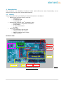
1.1 Identify
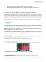
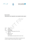
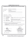
The picture below lets you identify the various functions on the board.
• RS232 level converter can be used by:
o Raspberry-Pi
o or Atmega-328
o or Atmega-48
• Atmega 328 (Arduino-Uno® compatible) with:
o Arduino-Uno® compatible connectors
o Reset button
o 2 user push buttons
o 6 LEDs.
• Atmega 48 with:
o I/O connector with 20 pins.
o High precision RTC crystal
o Battery backup power supply
o IRDA interface
PCB Overview:
R232
Jumpers
IRDA receiver
Battery for RTC
Atmega 48
Atmega 328
2 user buttons
6 LEDS
More I/O
Reset button
RTC X-tal
1: GertDuino Functions
Picture
3|Page
1.2 Comparison
There are some differences between a normal Arduino-Uno and the GertDuino.
Function
USB
Reset button
Power supply
3V3 supply
LED's
User pushbuttons
RS232 buffer
Real-Time-Clock
Infra-red interface
Arduino-Uno
Slave interface
Yes
7..12V, ~250mA
~50mA
One Not-buffered
-
GertDuino
Yes
<5V Raspberry-Pi>
~150mA.
Six Buffered
Two
Yes
Yes
Yes
Table 1: Comparison GertDuino vs Arduino-Uno
1.3 Vext
As the board does not have a separate supply the Vext is not connected. If you want it
connected you have to add the following components:
J1, L4 (or a short instead of L4), D20 (or a short instead of D20).
2
RS232/UART
The Gerduino board has a RS232 level converter which will convert the signals form a UART to
the RS232 standard voltages (And invert them as per that same standard). The RS232 signals
come from J12.
Pin 3 is the receive
Pin 2 is the transmit
Pin 1 is the ground
4|Page
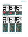
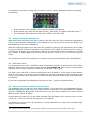
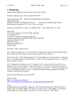
Connections can be made in many ways:
2.1 Atmega-328 & Pi UART
Pi to RS232 buffers
Atmega-328 to RS232 buffers
Raspberry-Pi
Atmega 328
Atmega 328
Atmega 328
RS232
buffers
RS232
buffers
Atmega
48
Atmega
48
Atmega
48
2.2
Raspberry-Pi
Raspberry-Pi
RS232
buffers
Pi to Atmega-328
Atmega-48 UART
Atmega-48 to RS232 buffers
Raspberry-Pi
Atmega 328
Atmega
48
Atmega-48 to Atmega-328
Raspberry-Pi
Raspberry-Pi
RS232
buffers
Atmega 328
Atmega
48
Atmega-48 to Pi
Atmega 328
RS232
buffers
RS232
buffers
Atmega
48
5|Page
3
3.1
Atmega-328
Features
This device is compatible with the Arduino Uno. In contrast to the 328 on the GERTBOARD this
device runs of 5V, has the 16MHz oscillator and has connectors which are 100% Arduino-Uno
compatible. It also contains the reset switch.
This board also has the following components which you will not find on the Uno:
• 2 User push buttons
• 6 LEDs 1
LEDs
One LED is connected to PB5 (aka Port-13 aka SCK). This is compatible with the UNO. The
GertDuino has a five more LEDs. The total list of LEDs is:
- PB5 (Port-13)
- PB1 (Port-9)
- PB2 (Port-10)
- PD3 (Port-3)
- PD5 (Port-5)
- PD6 (Port-6)
The LEDs are not directly connected but are buffered and thus do not give any significant load
on the signal pins.
User buttons
The two user buttons are connected to pins PC2 and PC3. They will only function correctly if the
pins have an internal or external pull-up. The button are connected through a 1K Ohm resistor
so they will not cause a short if a pin is set as output and the button is pressed.
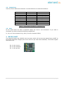
3.2 Program the Atmega-328
To program this device from the Raspberry-Pi you have to place the following 4 jumpers:
Then run the script Program 328as described in section 8.1.Atmega-328.
To program the 328 using a JTAG-ICE you need to use the "squid" cable and make the following
connections:
1
LED: The first debug tool any programmer grabs for.
6|Page
At the left there are the GND (white) and 5V (Purple) connections.
At the top row right are the Reset (green), Mosi (Red), Clk (Black) and Miso (Grey)2.
The equivalent JTAG names for these are: nSRST, TDI, TCK, TDO
3.3 Using/running the Atmega-328
When the device has been programmed it will run that program independent of the RaspberryPi. In fact you can remove the board from the Raspberry-Pi and use it standalone.
When developing programs you may leave the jumpers in place as the programme will tri-state
its pins and set the reset pin high when it has finished. This is NOT the case if the PI is reset or
not powered. Especially the reset-jumper needs to be removed otherwise the Raspberry-Pi GPIO
pin 8 (which is default low) will the keep the 328 device in reset or you can run the reset_off
script.
You should also remove the jumpers if you want to use any of the following pins: B3,B4,B5,C6.
4
4.1
Atmega-48
Features
This device is intended to be used as Real Time Clock (RTC) and/or as IRDA front end. However
it is also freely programmable by the user and thus can be used for any other application, giving
the user the power of not one but TWO Atmega devices to play with.
Note: The I2C interface of the Atmega-48 is connected permanently to the Raspberry-Pi I2C
interface <GOIO0/1 on rev1, GPIO 2/3 on rev2>.
Also beware that if you make programming errors with the Atmege-328 the device can easily be
replaced. This is not the case with the Atmega-48. It is therefore strongly recommended that
you are extra careful and do not damage any of the I/O ports.
Spare connections.
The following I/O pins of the Atmega-48 are not used and are brought out to a connector:
B0,B1,B2, B3, B4,B5, C0,C1,C2,C3,D0,D1,D4, D5, D6, D7.
Beware that B3, B4 and B5 are also used for programming the device.
4.2
Program the Atmega-48
To program the Atmega-48 from the Raspberry-Pi you have to place the following 4 jumpers:
The programming is the same as the 328 but replace "328p" with "48pa".
2
The colours used here are the same as on MY squid cable but I can't guarantee all squid cables are the same.
7|Page
To program the 48 using a JTAG-ICE you need to use the "squid" cable and make the following
connections:
At the left there are the GND (white) and 5V (Purple) connections.
At the bottom row right are the Reset (green), Mosi (Red), Clk (Black) and Miso (Grey).3
The equivalent JTAG names for these are: nSRST, TDI, TCK, TDO
4.3 Using/running the Atmega-48
What was written about the 328 also is valid for the 48: when the device has been programmed
it will run that program independent of the Raspberry-Pi. In fact you can remove the board from
the Raspberry-Pi and use it standalone.
When developing programs you may leave the jumpers in place as the programme will tri-state
its pins and set the reset pin high when it has finished. This is NOT the case if the PI is reset or
not powered. Especially the reset-jumper needs to be removed otherwise the Raspberry-Pi GPIO
pin 8 (which is default low) will the keep the 48 device in reset or you can run the reset_off
script.
You should also remove the jumpers if you want to use any of the following pins: B3,B4,B5,C6.
4.4
Real Time Clock
The Atmege-48 device has a 32768Hz crystal connected to operate as a Real-Time-Clock (RTC).
Example code for this can be found under section 8.2 Atmega-48. The Crystal is a high quality
type and under normal conditions a deviation is less than 1 sec/3 days.
The other part of the RTC is that the Atmega-48 has a 3V battery. It will switch to that battery
when the 5V power is removed. As the Atmega-48 is a fully programmed microcontroller it can
be set-up to perform other operations or hold other data when the main power of the BCM2835
is removed.
If you have programmed the Atmege-48 correctly it uses ~1µA when powered down.
4.5 Infra-red receiver/remote control receiver
The BCM2835 does not have a native IRDA interface. The protocol can be implemented using a
standard GPIO pin but that puts a very heavy burden on the CPU. To support IRDA the Atmega48 has a TSSOP4038 IRD device connected to pin D3. This device supports the most common
IRDA protocol: 38KHz IR signal.
Unfortunately we could not run the IRDA interface from the battery as it uses too much current
(~450 µA). Thus you need the 5V present for it to operate.
The IRDA can also be used if the GertDuino is used stand-alone to control the connected logic
using a remote control.
3
The colours used here are the same as on MY squid cable but I can't guarantee all squid cables are the same.
8|Page
Note that 95% of all TV/Video/CD remote controls use the 38KHz infra-red signal, but the
coding varies greatly from type to type.
4.6
Battery Drain
If a battery is present and the power of the Raspberry-Pi is switched of the Atmega-48 will still
remain powered by the Battery. It will also keep running. Unless the battery is removed or the
Atmega-48 is programmed to go into a special ultra-low-power condition, the battery will be
drained in a short time.
Even if you think the device is in ultra-low-power mode it can still consume power if it has to
drive outputs high.
Measurements have also show that if a UART connection exists between the Atmega-48 to the
Raspberry-Pi (even if it is not used) that increases the lower power current from 1µA to about
100µA.
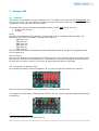
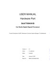
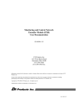
To measure the current consumption you have to use a 3V supply and connect it to the battery
holder but between the supply and the battery holder you have to place a current (Ampere)
meter. Optionally you can connect a scope on one of the I/O pins of the Atmege48 to see if the
program is running. You should NOT connect anything to one of the output which loads an I/O
pin as that will cause extra current consumption.
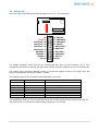
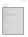
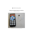
This is a block diagram of the setup:
A
Gertduino
3V
Atmega48pa
GND
And this is how it looks in real life:
The meter shows a current consumption of 1.3µAmp. (The meter is shown enlarged in the lower
left hand corner of the picture) .
9|Page
If possible limit the current from your power source to a few milli-amps. I managed to blow a
fuse of my meter performing the measurements because I accidentally shorted the supply when
placing the probe on the battery holder.
4.7
Atmega-48 LED trick
If you are debugging, an LEDs is often the first tool you reach for. But the Atmega-48 does not
have any LEDs. However the Atmega-328 does! There are two ways in which you can use these
LEDs :
•
•
The safest way is to remove the 328 from its socket.
The second way is to erase the 328 so that all its pins are inputs.
You can then use the connectors to feed a signal to an LED. Simplest way is to use a femalemale strap between connector J10 and e.g. pins, 2,3 or 6 of J14.
5
Connectors
The board contains a number of connectors. You will find that in the document the connectors of
the Atmega devices have two ways of numbering: There are the single numbers 0..13 and
A1..A3. These are the numbers used in many Arduino example programs. Alongside those I use
the official pin names (PB0..PB7, PD0..PD7, PCO..PC3). The latter are easier to use if you have
to work with the AVR datasheet.
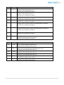
5.1 Alternate functions.
The Atmega-328 and the Atemege-48 have exactly the same pins with the same functionality.
The devices only differ in the size of their various memories. The following is a table of the pins
and all the functions they can carry. These where copied from the AVR datasheet. For details of
the functions you should read that datasheet.
10 | P a g e
#
-
Name
PB7
Functions
XTAL2 (Chip Clock Oscillator pin 2)
TOSC2 (Timer Oscillator pin 2)
PCINT7 (Pin Change Interrupt 7)
XTAL1 (Chip Clock Oscillator pin 1 or External clock input)
TOSC1 (Timer Oscillator pin 1)
PCINT6 (Pin Change Interrupt 6)
-
PB6
13
PB5
12
PB4
11
PB3
10
PB2
SS (SPI Bus Master Slave select)
OC1B (Timer/Counter1 Output Compare Match B Output)
PCINT2 (Pin Change Interrupt 2)
9
PB1
OC1A (Timer/Counter1 Output Compare Match A Output)
PCINT1 (Pin Change Interrupt 1)
8
PB0
ICP1 (Timer/Counter1 Input Capture Input)
CLKO (Divided System Clock Output)
PCINT0 (Pin Change Interrupt 0)
#
Name
A5
PC5
A4
PC4
A3
PC3
A2
PC2
A1
PC1
A0
PC0
SCK (SPI Bus Master clock Input)
PCINT5 (Pin Change Interrupt 5)
MISO (SPI Bus Master Input/Slave Output)
PCINT4 (Pin Change Interrupt 4)
MOSI (SPI Bus Master Output/Slave Input)
OC2A (Timer/Counter2 Output Compare Match A Output)
PCINT3 (Pin Change Interrupt 3)
Functions
ADC5 (ADC Input Channel 5)
SCL (2-wire Serial Bus Clock Line)
PCINT13 (Pin Change Interrupt 13)
ADC4 (ADC Input Channel 4)
SDA (2-wire Serial Bus Data Input/Output Line)
PCINT12 (Pin Change Interrupt 12)
ADC3 (ADC Input Channel 3)
PCINT11 (Pin Change Interrupt 11)
ADC2 (ADC Input Channel 2)
PCINT10 (Pin Change Interrupt 10)
ADC1 (ADC Input Channel 1)
PCINT9 (Pin Change Interrupt 9)
ADC0 (ADC Input Channel 0)
PCINT8 (Pin Change Interrupt 8)
11 | P a g e
#
Name
Functions
AIN1 (Analog Comparator Negative Input)
PCINT23 (Pin Change Interrupt 23)
AIN0 (Analog Comparator Positive Input)
OC0A (Timer/Counter0 Output Compare Match A Output)
PCINT22 (Pin Change Interrupt 22)
7
PD7
6
PD6
5
PD5
T1 (Timer/Counter 1 External Counter Input)
OC0B (Timer/Counter0 Output Compare Match B Output)
PCINT21 (Pin Change Interrupt 21)
4
PD4
3
PD3
XCK (USART External Clock Input/Output)
T0 (Timer/Counter 0 External Counter Input)
PCINT20 (Pin Change Interrupt 20)
INT1 (External Interrupt 1 Input)
OC2B (Timer/Counter2 Output Compare Match B Output)
PCINT19 (Pin Change Interrupt 19)
2
PD2
1
PD1
0
PD0
INT0 (External Interrupt 0 Input)
PCINT18 (Pin Change Interrupt 18)
TXD (USART Output Pin)
PCINT17 (Pin Change Interrupt 17)
RXD (USART Input Pin)
PCINT16 (Pin Change Interrupt 16)
5.2 Atmega-328
The Atmega-328 pins are brought to connectors compatible with the Arduino-Uno.
J14
J7
1
1
1
1
1
1
1
1
1
1
1
1
1
1
Pin
No.
10
9
8
7
6
5
4
3
2
1
1
Signal
A5/PC5/SCL
A4/PC4/SDA
AREF
Ground
13/PB5/SCK/LED0
12/PB4/MISO
11/PB3/MOSI
10/PB2/SS/LED2
9/PB1/PCINT1/LED1
1
Pin
No.
8
7
6
5
4
3
2
1
1
Signal
7/PD7/AIN1
6/PD6/AIN0/LED6
5/PD5/T1/LED5
4/PD4/T0
3/PD3/INT1/LED4
2/PD2/INT0
1/PD1/TXD
0/PD0/RXD
12 | P a g e
1
8/PB0/CLK0
Pin 1 is on the right-hand side so these tables top-to-bottom are the pins from left-to-right.
J9
J6
1
1
1
1
1
1
1
1
1
1
1
1
1
1
Pin
No.
8
7
6
5
4
3
2
1
1
1
Signal
NC
Ground
Ground
5V
3V3
Reset (Active low)
5V
NC
1
Pin
No.
6
5
4
3
2
1
1
Signal
A5/PC5/SCL
A4/PC4/SDA
A3/PC3/ADC3/BUT1
A2/PC2/ADC2/BUT0
A1/PC1/ADC1
A0/PC0/ADC0
Pin 1 is on the left-hand side so these tables top-to-bottom are the pins from right-to-left.
Beware that Pin 8 of J9 is normally connected directly to the input voltage which has been
removed and thus is NC here.
13 | P a g e
5.3 Atmega-48
All unused pin of the Atmega-48 are brought out to a 20 -pin connector:
1
1
1
1
1
1
1
1
5V
VBAT/5V
ADC0/PC0 : A0
ADC1/PC1 : A1
ADC2/PC2 : A2
ADC3/PC3 : A3
RXD/PD0 : 0
TXD/PD1 : 1
T0/PD4 : 4
Ground
1
20
1
13 : PB5/SCK
12 : PB4/MISO
11 : PB3/MOSI
10 : PB2/SS
9 : PB1/PCINT1
8 : PB0/CLK0
7 : PD7/AIN1
6 : PD6/AIN0
5 : PD5/T1
Ground
The supply 5V/VBAT which goes to the Atmega-48 also goes to the connector pin 3. Any
equipment connected to that pin will also draw current from the battery if the 5V is switched off.
The supply comes through a Schottky diode so the actual voltage is lower: ~4.5 Volts. Also the
current consumption should be limited ~100mA.
The following pins of the ATmega-48 are dedicated connected:
Pin
PD2
Hard wired to
5V Supply
Function
Detect absence of 5V supply (for RTC)
PD3
PC5
PC4
PB7
PB6
PC6
IRDA output
SCL
SDA
XTAL1
XTAL2
Program reset
Receive IRDA signal
I2C connection with the Pi
I2C connection with the Pi
32768Hz Tuning crystal
32768Hz Tuning crystal
Reset when programming
The Atmege-48 does not have a dedicated reset pin as that would interfere with its function as
real-time-clock. A reset can be obtained by pulling pin 4 of J13 low.
14 | P a g e
5.4 Raspberry-Pi
All connections between the board and the Raspberry-Pi are protected against 5V signals. The
I2C bus has FET level switches. All the other signals use resistive dividers.
The following connections of the Raspberry-Pi are used:
5V
3V3 ( I2C level converters only)
GPIO0/2 (I2C SDA)
GPIO1/3 (I2C SCL)
The following connections of the Raspberry-Pi are used if the programming jumpers or UART
jumpers are placed:
GPIO14
GPIO15
GPIO8
GPIO9
GPIO10
GPIO11
(UART-Tx)
(UART-Rx)
(Reset)
(MISO)
(MOSI)
(SCLK)
15 | P a g e
6
Frequently Asked Questions (FAQs)
Some questions you may ask and the answers.
avrdude: AVR device not responding
Q: When I try to program the device I get an error: "avrdude: AVR device not responding."
A: The most likely cause is that you have forgotten to place the four programming jumpers.
See section 3.2 Program the Atmega-328.
Why is my program slow?
Q: When I run the program it is very slow. Where I expect a delay of 1second it takes much
longer.
A: Straight from the factory the CPU runs from the internal 8MHz clock and that is divided by
8. Thus the processor runs at 1 MHz. To switch to the full speed, using the external 16MHz
oscillator run the avrdude command as described in 8.1Atmega-328under "Initial clock
setup"
Why does my program not run?
Q: When I upload the program it runs fine but when I halt the Raspberry-Pi or when I start the
Raspberry-Pi my program does not work.
A: GPIO 8 controls the Reset of the Arduino. This pins must be high but for your program to
run. The simplest solution is to remove the programming jumpers. Alternative is to program
the GPIO-8 pin high using the reset_off script. The avrdude with the -c gpio option does this
for you so normally after programming the reset has been removed.
I have a different compiler
Q: I use the AVR compiler on my PC. How do I program the Atmega on the Raspberry-Pi?
A: I have only experience with the GCC version (AVR 5.1 and higher). After compilation you
find a .hex file in the debug directory. You have to transfer that file somehow to the
Raspberry-Pi and use the programmer script Program 328 as described in 8.1Atmega-328
to program the device(s) on the GertDuino. (If you have the script already installed use
"./program_328 <hex file>)
The Raspberry-Pi boots different: it has big text and not the normal prompt!
Q: When I plug the GertDuino on the Raspberry-Pi it boots different: It has big text and not the
normal prompt!
A: Pin 5 of the GPIO connector is used to indicate ‘safe boot mode’. If that pin is low when
booting the Raspberry-Pi boots in “safe mode”. Pin 5 is also connected to the Atmge-48. It
is one of the I2C pins. Thus if your 48 is driving a LOW on that pin the Pi always boots in
safe
mode.
To prevent this you can put “avoid_safe_mode=1” in the config.txt file and the pi will boot
normally.
Why is there no battery supplied
Q: The GertDuino has a battery holder but there is no battery in there. Why do I have to buy
my own?
A: These batteries are lithium batteries. Those are classified as ‘Dangerous Goods’ and
require special paper work, warning labels and other precautions when shipped. And that is
for shipping within the UK. International shipping becomes a nightmare. So we decided to
leave it off.
16 | P a g e
7
How to start
Before you can program the devices you need to have a cross compiler. A cross compiler is a
compiler which runs on one type of processor, but generates code for a different type. In this
case the compiler runs on the Raspberry-Pi (ARM11 device) but makes code for the Atmel
devices.
7.1 On the Raspberry-Pi:
When programming the Atmel devices on the Raspberry-Pi you have two choices:
•
•
Use the Arduino GUI
Use the GCC Atmel compiler
For both you need to have a cross compiler for the Atmega devices. Easiest is to install the
Arduino package:
sudo apt-get install arduino
avrdude
You need to use a program called "avrdude" to program the devices BUT you need a special
version of "avrdude" which can program the devices using the GPIO of the Raspberry-Pi. Thanks
for Gordon Henderson (projects.drogon.net) who has provided these:
Standard Debian Squeeze:
cd /tmp
wget http://project-downloads.drogon.net/gertboard/avrdude_5.10-4_armel.deb
sudodpkg -i avrdude_5.10-4_armel.deb
sudochmod 4755 /usr/bin/avrdude
Debian Raspbian:
cd /tmp
wget http://project-downloads.drogon.net/gertboard/avrdude_5.10-4_armhf.deb
sudodpkg -i avrdude_5.10-4_armhf.deb
sudochmod 4755 /usr/bin/avrdude
You can now compile programs for the Atmega devices and upload the program into the chip on
the GertDuino. Example source code, Makefile and how to upload the program can all be found
in section 8 Example programs.
If you want to use the Arduino development environment you have to adapt it. See
projects.drogon.net/raspberry-pi/gertboard/arduino-ide-installation-isp/ how to do that.
7.2
On a PC
Atmel have a free C-compiler. You can get information about the latest version here:
http://www.atmel.com/tools/ATMELSTUDIO.aspx
You can compile on the PC but you need to transfer the final .hex file to the Raspberry-Pi before
you can program the Atmega devices.
17 | P a g e
Alternative is that you buy a JTAG-ICE box and use that to program and the devices but that is
a lot more expensive. It does have the advantage that you can use it for debugging as well:
Step through the program, set breakpoints ,inspect variables etc.
18 | P a g e
8
8.1
Example programs
Atmega-328
blink.c source code:
/*
* blink.c
*
* Created: 23/09/2013 21:04:02
* Author: G.J. van Loo
* Simple example program to 'walk' the LEDs
*/
#include <avr/io.h>
#define DELAY 250
#define F_CPU 16000000
// Some
#define
#define
#define
#define
//
//
//
//
//
//
//
macros that make the code more readable
output_low(port,pin) port &= ~(1<<pin)
output_high(port,pin) port |= (1<<pin)
set_input(portdir,pin) portdir&= ~(1<<pin)
set_output(portdir,pin) portdir |= (1<<pin)
Outputs are:
LED0 = PB5
LED1 = PB1
LED2 = PB2
LED3 = PD3
LED4 = PD5
LED5 = PD6
void delay_ms(unsigned intms)
{
uint16_t delay_count = F_CPU / 17500;
volatile uint16_t i;
while (ms != 0) {
for (i=0; i != delay_count; i++);
ms--;
}
} // delay_ms
void delay()
{ long d;
unsigned char oldb,oldd;
for (d=0; d<DELAY; d++)
{
delay_ms(1);
if ((PINC & 0b00001000)==0)
{
oldb = PORTB;
oldd = PORTD;
PORTB = 0xFF;
PORTD = 0xFF;
delay_ms(1);
PORTB = oldb;
19 | P a g e
PORTD = oldd;
d--;
}
else
{ if ((PINC & 0b00000100)==0)
d--;
else
delay_ms(1);
}
// if button pressed
} // if button pressed
} // delay
int main(void)
{ // int b;
// Set all LED connections to output
DDRB = 0b00100110;
DDRD = 0b01101000;
PORTB = 0x00;
PORTD = 0x00;
// Set button (port C) to input
DDRC = 0b00000000;
// pull-up on C2 & C3:
PORTC = 0b00001100;
while(1)
{ // convoluted but simple walk the leds
output_high(PORTB,5);
delay();
output_low (PORTB,5);
output_high(PORTB,1);
delay();
output_low (PORTB,1);
output_high(PORTB,2);
delay();
output_low (PORTB,2);
output_high(PORTD,3);
delay();
output_low (PORTD,3);
output_high(PORTD,5);
delay();
output_low (PORTD,5);
output_high(PORTD,6);
delay();
output_low (PORTD,6);
output_high(PORTD,5);
delay();
output_low (PORTD,5);
output_high(PORTD,3);
delay();
output_low (PORTD,3);
output_high(PORTB,2);
delay();
output_low (PORTB,2);
output_high(PORTB,1);
delay();
output_low (PORTB,1);
} // forever
} /} // main
20 | P a g e
Makefile
# Makefile:
#
Make the GertDuino m328p firmware.
#
# Copyright (c) 2013 Gordon Henderson <[email protected]>
#################################################################################
# This file is part of gertduino-m328:
#Software to run on the Atmega328p processor on the Gerduino board
#Can be used for the Atmega328p processor on the GERTBOARD as well
#
This is free software: you can redistribute it and/or modify
#
it under the terms of the GNU General Public License as published by
#
the Free Software Foundation, either version 3 of the License, or
#
(at your option) any later version.
#
#
This is distributed in the hope that it will be useful,
#
but WITHOUT ANY WARRANTY; without even the implied warranty of
#
MERCHANTABILITY or FITNESS FOR A PARTICULAR PURPOSE. See the
#
GNU General Public License for more details.
#
#
You should have received a copy of the GNU General Public License
#
along with this. If not, see <http://www.gnu.org/licenses/>.
#################################################################################
TARGET=blink
MCU=atmega328p
FREWQ=16000000
# Debug
#DEBUG
= -gstabs
# C flags
CC
= avr-gcc
#CFLAGS = $(DEBUG) -O3 -Wall -std=gnu99 -mmcu=$(MCU) -DF_CPU=$(FREWQ) $(INCLUDE)
CFLAGS = $(DEBUG) -O2 -mcall-prologues -Wall -std=gnu99 -mmcu=$(MCU) DF_CPU=$(FREWQ) $(INCLUDE)
LD
= avr-gcc
#LDFLAGS2=-Wl,-uvfprintf -lprintf_flt
LDFLAGS = -mmcu=$(MCU) $(DEBUG) $(LIBLOC) $(LDFLAGS2)
#LIBS
= -ldross -lm
SRC
=
$(TARGET).c
OBJ
=
$(SRC:.c=.o)
all:
$(TARGET).hex
$(TARGET).hex: $(TARGET).elf
@echo [hex] $<
@avr-objcopy -j .text -j .data -O ihex $(TARGET).elf $(TARGET).hex
$(TARGET).elf:
$(OBJ)
@echo [Link] $<
@$(LD) -o $@ $(OBJ) $(LDFLAGS) $(LIBS)
@avr-size $(TARGET).elf
# Generate .lst file rule
%.lst : %.o
@echo [lst] $<
@avr-objdump -h -S $<> $@
21 | P a g e
.c.o:
@echo [CC] $<
@$(CC) -c $(CFLAGS) $< -o $@
.PHONEY:
clean
clean:
rm -f *.o *.elf *.hex *.lst Makefile.bak *~
Program 328
#!/bin/bash
# script to program 328p device using AVRDUDE and a hex file
if [ "$1" == "" ]; then echo Missing argument
exit 1;
fi
# if ends in .hex use full argument
# otherwise add the .hex
ext=${1:${#1}-4}
if [ "$ext" == ".hex" ]; then
/usr/bin/avrdude -c gpio -p m328p $1 -Uflash:w:$1
else
/usr/bin/avrdude -c gpio -p m328p $1.hex -Uflash:w:$1.hex
fi
Save the above code in a file called program_328 and then run "chmod 777 program_328". Use
./program_328 <hex file> to program the Atmega device.
Initial clock setup
avrdude -qq -c gpio -p atmega328p -U lock:w:0x3F:m
U lfuse:w:0xE7:m -U hfuse:w:0xD9:m
-U efuse:w:0x07:m -
You normally run the above command when you get a brand new device. It programs the
Atmega328 to use the external 16MHz Crystal.
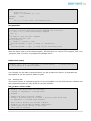
8.2 Atmega-48
This section shows an example program for the Atmega48. You will find that the makefile and
the programming files are very similar to the 328 example.
low_power.c source code:
//
//
//
//
//
//
//
//
//
//
//
//
Example code which uses the 32767KHz
Crystal to implement a 1-second event
handler
Atmega Low power operation example
Using a 32768 Khz crystal on timer 2 and full power down mode
to implement a 1-second event handler
This code is written for the GCC compiler
Example for the GertDuino Atmega 48PA device
(This program will NOT run on the 328!)
This code is freeware
22 | P a g e
//
#include <avr/interrupt.h>
#include <avr/sleep.h>
volatile unsigned long count_seconds;
main()
{
// set PB0 as output
DDRB = 0xFE;
// Set-up 32 KHz oscillator
TIMSK2 = 0x00;
// No interrupts
ASSR
= 0x20;
// async run from xtal
TCNT2 = 0;
// clear counter
TCCR2B = 0x05;
// prescale 5=/128
// Wait for all 'busy' bits to be clear
// That happens on the first timer overflow
// which can take 8 seconds if you have a max pre-scaler!!
while (ASSR&0x07) ;
TIMSK2 = 0x01;
// overflow IRQ enable
count_seconds = 0; // clear seconds counter
sei();
//set the Global Interrupt Enable Bit
while (1)
{
SMCR = 0x7; // Go into lowest power sleep mode
asm("sleep");
asm("nop");
// Interrupt woke us up
// If we get here the interrupt routine has already been called
// Toggle LED on port B0 using LS timer bit
PORTB = count_seconds & 0x01;
}
} // main
//
// Timer 2 overflow
// if we set timer2 up correctly this routine is called every second
//
ISR(TIMER2_OVF_vect)
{ count_seconds++; // all we do here is count seconds elapsed
}
23 | P a g e
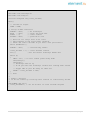
Makefile:
# Makefile:
# Make the GertDuino m48p firmware.
#
# Copyright (c) 2013 Gordon Henderson <[email protected]>
###########################################################################
# This file is part of gertduino-m328:
#Software to run on the Atmega328p processor on the Gerduino board
#Can be used for the Atmega328p processor on the GERTBOARD as well
#
This is free software: you can redistribute it and/or modify
#
it under the terms of the GNU General Public License as published by
#
the Free Software Foundation, either version 3 of the License, or
#
(at your option) any later version.
#
#
This is distributed in the hope that it will be useful,
#
but WITHOUT ANY WARRANTY; without even the implied warranty of
#
MERCHANTABILITY or FITNESS FOR A PARTICULAR PURPOSE. See the
#
GNU General Public License for more details.
#
#
You should have received a copy of the GNU General Public License
#
along with this. If not, see <http://www.gnu.org/licenses/>.
###########################################################################
TARGET=low_power
MCU=atmega48p
FREWQ=1000000
# Debug
#DEBUG
= -gstabs
# C flags
CC
= avr-gcc
#CFLAGS
= $(DEBUG) -O3
-Wall -std=gnu99 -mmcu=$(MCU) DF_CPU=$(FREWQ) $(INCLUDE)
CFLAGS
= $(DEBUG) -O2 -mcall-prologues -Wall -std=gnu99 -mmcu=$(MCU) DF_CPU=$(FREWQ) $(INCLUDE)
LD
= avr-gcc
#LDFLAGS2=-Wl,-uvfprintf -lprintf_flt
LDFLAGS = -mmcu=$(MCU) $(DEBUG) $(LIBLOC) $(LDFLAGS2)
#LIBS
= -ldross -lm
SRC
=
$(TARGET).c
OBJ
=
$(SRC:.c=.o)
all:
$(TARGET).hex
$(TARGET).hex: $(TARGET).elf
@echo [hex] $<
@avr-objcopy -j .text -j .data -O ihex $(TARGET).elf $(TARGET).hex
$(TARGET).elf:
$(OBJ)
@echo [Link] $<
@$(LD) -o $@ $(OBJ) $(LDFLAGS) $(LIBS)
@avr-size $(TARGET).elf
# Generate .lst file rule
%.lst : %.o
@echo [lst] $<
@avr-objdump -h -S $<> $@
24 | P a g e
.c.o:
@echo [CC] $<
@$(CC) -c $(CFLAGS) $< -o $@
.PHONEY:
clean
clean:
rm -f *.o *.elf *.hex *.lst Makefile.bak *~
Program 48
#!/bin/bash
# script to program 48pa device using AVRDUDE and a hex file
if [ "$1" == "" ]; then
echo Missing argument
exit 1;
fi
# if ends in .hex use full argument
# otherwise add the .hex
ext=${1:${#1}-4}
if [ "$ext" == ".hex" ]; then
/usr/bin/avrdude -c gpio -p m48p $1 -Uflash:w:$1
else
/usr/bin/avrdude -c gpio -p m48p $1.hex -Uflash:w:$1.hex
fi
Save the above code in a file called "program_48" and then run "chmod 777 program_48". Use
./program_48 <hex file> to program the Atmega 48 device.
9
Control Arduino Reset
The Raspberry-Pi GPIO 8 pin controls the Arduino reset pin when the jumpers are in place.
When starting the pin is LOW and thus the Arduino chip is held in reset. To control the reset
(gpio-8 pin) you can use the scripts shown below.
Don’t forget to change the mode of the text file to executable format: (chmod 777 reset_off).
Depending on your path you may have to call the script starting with a <dot><slash>:
“./reset_off”.
Alternative copy the scripts to /usr/bin: “sudo cp reset_off /usr/bin”. If you want the Raspberry
Pi to always execute the script at boot up you have to edit the /etc/rc.local file. Make sure that
you have the full path in there. Thus if you have installed the script in /usr/bin you have to add
the following line to /etc/rc.local:
/usr/bin/reset_off
25 | P a g e
reset_off
The following script will release the Arduino reset and thus make that the Arduino chip runs. It
only works if the GertDuino is plugged in to the Raspberry Pi and the reset jumper is in place.
#!/usr/bin/sudo bash
# Set GPIO pin 8, high releasing Arduino reset
sudo echo "8"
>/sys/class/gpio/export
sudo echo "out" >/sys/class/gpio/gpio8/direction
sudo echo "1"
>/sys/class/gpio/gpio8/value
sudo echo "8"
>/sys/class/gpio/unexport
reset_on
The following script will assert the Arduino reset and thus make that the Arduino chip stops, is
held in reset. It only works if the GertDuino is plugged in to the Raspberry Pi and the reset
jumper is in place.
#!/usr/bin/sudo bash
# Set GPIO pin 8, low activating Arduino reset
sudo echo "8"
>/sys/class/gpio/export
sudo echo "out" >/sys/class/gpio/gpio8/direction
sudo echo "0"
>/sys/class/gpio/gpio8/value
sudo echo "8"
>/sys/class/gpio/unexport
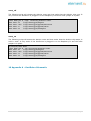
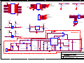
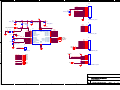
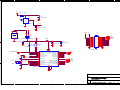
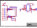
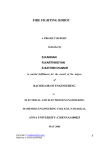
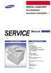
10 Appendix A : GertDuino Schematic
26 | P a g e
5
4
3
2
1
J17
3V3_RASP
J1
5V
R15 12K_0603
GPIO15
1
3
5
7
9
11
13
15
17
19
21
23
25
GPIO0/2
GPIO1/3
GPIO4
GPIO17
GPIO21
GPIO22
D
MOSI
MISO
SCLK
GPIO10
GPIO9
GPIO11
2
4
6
8
10
12
14
16
18
20
22
24
26
2
4
6
8
10
12
14
MISO
SCK
MOSI
DBG
GPIO14 Tx
GPIO15 Rx
GPIO18
SER_TX
SER_RX
5V
GPIO23
GPIO24
1
3
5
7
9
11
13
MC_MISO
MC_SCK
MC_MOSI
MC_DBG/RESETn
pi_tx
pi_rx
pi_rx
R9 1K5_0603
GPIO8
R16
22K_0603
DBG
R10
2K7_0603
D
HEADER 7X2
GPIO25
GPIO8
GPIO7
RN3
1
2
3
4
5
6
J13
3V3_RASP
GPIO10
GPIO9
GPIO11
GPIO14
EX_MISO
EX_SCK
EX_MOSI
EX_DBG/RESETn
PD1
PD0
5
6
7
8
MOSI
MISO
SCK
pi_tx
3K3X4_TC164
HEADER 6X1
5V
RN4
5K6X4_TC164
LOC3V3
U4
3
3
C23
100nF_0603
2N7002
3V3_RASP
VIN VOUT
SDA
1
Q1
SDA
2
GND
2
GPIO0/2
5V
5V
C24
100nF_0603
APL5320-33AI-TRG
R is on Pi
Vin
BAS70-06/SOT23
1
1
R13
2K7_0603
Do Not Fit
3
2
SCL
U6
D2
5
FB_1206
C25
1nF_0603
SS/EN
L1 6u8H
Switch
COMP
22pF_0603
C18
C16
R28
12K7-0603
C27
1nF_0603
FB
1
[wurth]
7
R30
C21
100nF_0603
33K2_0603
SC4525C
22uF_1210_20V
C15
+
1
2
3
6
56K_0603
RSET
L4
R21
D20
B330A-13-F
1
2
Vin
B
PAD
TS4148RY
D23
5V
9
2
330nF_0603
C20
GND
2N7002
4
Q2
SCL
8
3
Boost
2
B
3
GPIO1/3
C
1
2
3
4
R8
2K7_0603
1
R is on Pi
C
A
4
3
2
1
8
7
6
5
CONNECTOR_13X2
RGA221M1VBK-1013G
R20
22K_0603
330nF_0603
2n2F_0603
C19
R29
15K8_0603
D21
R31
8K25_0603
B330A-13-F
C22
22uF_1206
GRM31CR60J476M
C17
J11
CON_PWR3
A
Title
Gertduino Pi & Power
Size
A4
Date:
5
4
3
2
Document Number
Saturday, September 28, 2013
Rev
5.1
Sheet
1
1
of
4
5
4
3
2
1
J14
PC5
PC4
AREF
MC_SCK
MC_MISO
MC_MOSI
SS
PB1
PB0
C1
100nF_0603
D
10
9
8
7
6
5
4
3
2
1
5V
C2
100nF_0603
CONNECTOR_10X1
C3
4u7F_0805
TS4148RY
D1
C4
C14
1
2
3
4
5
6
PD5
PD6
PD7
PB0
9
10
11
12
13
14
12pF_0402
XTAL_IN
Y1
16MHz
C26
12pF_0402
7
20
21
PC6/Reset_n
PD0/RXD
PD1/TXD
PD2/INT0
PD3/INT1/OC2B
PD4/XCK/T0
ADC5/SCL/PC5
ADC4/SDA/PC4
ADC3/PC3
ADC2/PC2
ADC1/PC1
ADC0/PC0
PB6/XTAL1
PB7/XTAL2
PD5/OC0B/T1
PD6/OC0A/AIN0
PD7/AIN1
PB0/CLK0/ICP1
SCK/PB5
MISO/OC2A/PB4
MOSI/OC2A/PB3
SS_n/OC1B/PB2
OC1A/PB1
ATmega328P
J8
XTAL_IN
VCC
AVCC
AREF
C
PD0
PD1
PD2
PD3
PD4
GND
GND
3
4
28
27
26
25
24
23
19
18
17
16
15
PC5
PC4
PC3
PC2
PC1
PC0
SS
PB1
6
5
4
3
2
1
C
CONNECTOR_6X1
MC_SCK
MC_MISO
MC_MOSI
J7
PD7
PD6
PD5
PD4
PD3
PD2
PD1
PD0
8
22
S1
PC5
PC4
PC3
PC2
PC1
PC0
AREF
U1
1
2
J6
100nF_0603
22K_0603
R17
MC_DBG/RESETn
D
PD1
PD0
1
8
7
6
5
4
3
2
1
CONNECTOR_8X1
HEADER 1X1
B
LOC3V3
MC_SCK
PB1
SS
PD3
PD5
PD6
PC2
PC3
LED0
LED1
LED2
LED3
LED4
LED5
B
5V
MC_DBG/RESETn
BUT0
BUT1
Vin
Vin
1
2
3
4
5
6
7
8
J9
CONNECTOR_8X1
A
A
Title
Gertduino Arduino
Size
A4
Date:
5
4
3
2
Document Number
<Doc>
Saturday, September 28, 2013
Rev
5.1
Sheet
2
1
of
4
5
4
D
3
2
1
D
5V
3
R40 330_0603
C10
Gnd Vcc
U9
100nF_0603
1
Out
2
TSOP38238
IRDA
C28
100nF_0603_DNF
3
C
2
D25
5V
BAT_HOLD_CR1025
BAT54C_SOT23
3
1
B1
5V
J10
1
VEXT
GND
VCC
C
VCC
2
5V
VEXT
C7
100nF_0603
C9
D4
22K_0603
R18
EXC0
EXC1
EXC2
EXC3
EXD0
EXD1
EXD4
100nF_0603
22K_0603
R19
C8
4u7F_0805
1
3
5
7
9
11
13
15
17
19
2
4
6
8
10
12
14
16
18
20
EXB2
EXB1
EXB0
EXD7
EXD6
EXD5
EX_SCK
EX_MISO
EX_MOSI
TS4148RY
EXD5
EXD6
EXD7
EXB0
5
6
7
8
9
10
0pF_0402_DNF
12.5pF 2
ESR=50K 3
X1
XTAL_SMD
1
XTAL1=18pF
4 XTAL2=8pF
C12
10pF_0402
3
16
17
ADC5/SCL/PC5
ADC4/SDA/PC4
ADC3/PC3
ADC2/PC2
ADC1/PC1
ADC0/PC0
PB6/XTAL1
PB7/XTAL2
PD5/OC0B/T1
PD6/OC0A/AIN0
PD7/AIN1
PB0/CLK0/ICP1
SCK/PB5
MISO/OC2A/PB4
MOSI/OC2A/PB3
SS_n/OC1B/PB2
OC1A/PB1
ATMEGAx48PA_28MLF
PAD
C11
PC6/Reset_n
PD0/RXD
PD1/TXD
PD2/INT0
PD3/INT1/OC2B
PD4/XCK/T0
24
23
22
21
20
19
15
14
13
12
11
SDA
EXC3
EXC2
EXC1
EXC0
EXB2
EXB1
SCL
SDA
B
EX_SCK
EX_MISO
EX_MOSI
29
IRDA
EXD4
EXD0
EXD1
GND
GND
EX_DBG/RESETn
4
18
B
HEADER 10X2
VCC
AVCC
AREF
U10
25
26
27
28
1
2
A
A
Title
Gertduino Atmega
Size
A4
Date:
5
4
3
2
Document Number
<Doc>
Saturday, September 28, 2013
Rev
5.1
Sheet
3
1
of
4
5
4
5V
D
3
2
VCC
5V
D
74HC14D power connection.
2
C39
100nF_0603
5V
3
M74HC14TTR
4
D5
LED
D6
LED
D7
LED
D8
LED
D9
LED
C41
100nF_0603
D10
LED
5
RN1
U3B
3
4
8
7
6
5
SER_TX
1
2
3
4
12
1KX4_TC164
C1+
C40
100nF_0603
C1C2+
C2-
V-
TX1_I
TX1_O
TX2_I
TX2_O
RX1_O
RX2_O
6
U8
MAX3232CUE
M74HC14TTR
V+
2
RX1_I
RX2_I
6
J12
14
7
3
2
1
13
8
C
HEADER 3X1
15
LED2
SER_RX
SER_RX
9
U3C
5
11
10
R39
22K_0603
M74HC14TTR
C
SER_TX
VCC
1
1
GND
U3A
LED1
C38
100nF_0603
16
C13
100nF_0603
LED0
1
C42
100nF_0603
U3E
LED3
11
10
M74HC14TTR
U3D
LED4
9
8
1KX4_TC164
M74HC14TTR
U3F
B
LED5
13
12
5
6
7
8
4
3
2
1
B
M74HC14TTR
RN2
1
2
S2
BUT0
3
4
1
2
S3
BUT1
3
4
A
A
Title
Gertduino I/O
Size
A4
Date:
5
4
3
2
Document Number
<Doc>
Saturday, September 28, 2013
Rev
5.1
Sheet
4
1
of
4