1
Using an Infrared Library on Arduino
Created by Chris Young
Last updated on 2015-02-26 05:00:06 PM EST
Guide Contents
Guide Contents
Overview
About IR libraries
Receiving and Decoding IR
Software installation
Hardware Needed
Decoding IR Data
How It Works
Protocol Specific Issues
NEC Repeat Codes
Sony Triple Messages
RC5 and RC6 Toggle Bits
Controlling NeoPixels with IR
Controlling a Servo with IR
Setting up the Example
Upload the Code
How It Works
Special Instructions for ATmega32u4 based systems
Sending IR Codes
Hardware Issues
Loading the Software
Sending and Receiving in the Same Program
All photos, videos and wiring courtesy Kenneth Young
© Adafruit Industries
https://learn.adafruit.com/using-an-infrared-library
2
3
4
5
5
5
7
8
9
9
10
10
11
14
14
15
17
17
19
19
21
22
23
Page 2 of 23
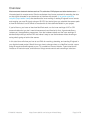
Overview
Most consumer electronic devices such as TV, cable box, DVD players and other devices use
infrared signals for remote control. Each manufacturer has its own protocols for encoding the data
so that signals intended for one device do not interfere with another. In an earlier tutorial by
LadyAda (http://adafru.it/ez6) she describes the inner working of reading IR signals from a remote
and creating your own IR signals using an IR LED. Her tutorial gives you a behind-the-scenes peek
at how IR works but it's a bit difficult to wrestle with all those technical details in your project.
If you're like me, you have no idea how NeoPixels work, nor the inner workings of I2C or SPI
communications but you don't need to because we have libraries for that. A good code library
isolates you, the application programmer, from the hardware details and the inner workings of
devices and provide you with an API that makes it easy to use the hardware without knowing or
caring what's going on behind the scenes.
In this tutorial we will show you how to use IRLib for receiving, decoding, and sending IR signals in
your Arduino based project. We will show you how to change colors on a NeoPixel, control a servo
using IR remote and send signals to your TV or cable box from an Arduino. Future tutorials will
include an IR control mouse, and Internet of things remote control and controlling a robot arm.
© Adafruit Industries
https://learn.adafruit.com/using-an-infrared-library
Page 3 of 23
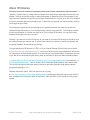
About IR libraries
IR signals consists of a series of modulated pulses called "marks" separated by intervals called
"spaces". Typically there is a long mark and space at the beginning of each signal that serves as a
header. Then by varying the timing of marks and spaces, a sequence of bits is transmitted. If you
had to store the precise timing of the entire signal it would take an array of up to 100 16 bit integers.
In order to compare the data received to see if it was what you wanted, you would similarly need to
store large arrays of data.
Fortunately the signals are sent according to very specific protocols that allow you to take this
received timing data and turn it into a single binary number of up to 32 bits. The IR library collects
the timing information in a buffer and then turns it into a single 32 bit value. You can then easily
compare that value to the one you want.
Similarly if you want to transmit IR signals, all you need to do is pass 32 bit value to the library and
tell it what protocol you want to use. It converts that value into a stream of marks and spaces with
the proper headers, bit encodings and timings.
The gold standard of IR libraries is "LIRC" or Linux Infrared Remote Control which can be found
at http://www.lirc.org/ (http://adafru.it/ez7). It consists of drivers and a large database of information
on hundreds of various remote controls. If we are using a Linux based system it's definitely the way
to go. We will not be discussing that library here as we intend to focus on Arduino based systems.
In August 2009 Ken Shirrff published "IRremote" on his blog (http://adafru.it/cJI) and released it on
GitHub (http://adafru.it/cR1). Then in January 2013 I released IRLib based on Ken's earlier work.
This revision reorganize the code making it easier to add new protocols using object-oriented
programming design in C++.
Detailed information about IRLib can be found on my blog
at http://tech.cyborg5.com/irlib/ (http://adafru.it/ez8). It includes an extensive user manual which is
also available in the "manuals" folder of the library.. We'll use IRLib in this tutorial to help you get
started.
© Adafruit Industries
https://learn.adafruit.com/using-an-infrared-library
Page 4 of 23
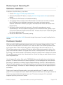
Receiving and Decoding IR
Software installation
Installation of the IRLib library is as follows:
1. Visit the IRLib page on GitHib (http://adafru.it/ez9).
2. Select the “Download ZIP” button, or simply click this link (http://adafru.it/eza) to download
directly.
3. Uncompress the ZIP file after it’s finished downloading.
4. The resulting folder should be named "IRLib-master" and will contain a number of header
files, IRLib.cpp and two subfolders containing a user manual and some example
sketches. Sometimes in Windows you’ll get an intermediate-level folder and need to move
things around.
5. Rename the folder (containing the .cpp and .h files and the examples and manual
subdirectories) to “IRLib” and place it alongside your other Arduino libraries, typically in your
(home folder)/Documents/Arduino/Libraries folder. Libraries should not be installed alongside
the Arduino application itself.
6. Re-start the Arduino IDE if it’s currently running.
Here’s a tutorial (http://adafru.it/aYM) that walks through the process of correctly installing Arduino
libraries.
Hardware Needed
IRLib runs on 8-bit AVR based Arduino boards such as Uno, Leonardo, Mega and Micro. It also
runs on the Leonardo portion of the Arduino Yun. It does not work on 32-bit ARM processors such
as the Arduino Due or other Arduino-like systems. Unfortunately at this time it does not run on
ATtiny85 base systems such as Adafruit Trinket and Adafruit Gemma but support for that is in the
job jar and should be available in a stripped-down version for those platforms in the near future. At
this writing, it has not been tested on the Adafruit Trinket Pro however since it is based on the same
ATmega328 processor as the Uno, it should work fine. So the first thing you need is Arduino Uno or
other compatible board.
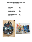
You will need an IR receiver. Such as the TSOP38238 shown on the right column under featured
products. This device combines an IR sensitive photocell, a 38 kHz bandpass filter, and automatic
gain control. It operates on a variety of supply voltages including 3.3v and 5v. It de-modulates the
received IR signal and gives you a nice clean square wave of off and on pulses at the voltage level
of your power supply. This means it is ideal for feeding its output directly into the digital input pin of
our Arduino.
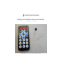
Finally you will need an IR remote such as you use for controlling your TV, cable box, or DVD
player. All of our examples will use the Adafruit Mini Remote Control shown on the right however we
will show you how to detect what protocol your own TV remote is using and if it is a protocol
supported by IRLib you can use it instead.
© Adafruit Industries
https://learn.adafruit.com/using-an-infrared-library
Page 5 of 23
Connecting the IR receiver is very simple. Connect the left-hand pin to any digital input pin on your
Arduino. In our examples we will use pin 11. Connect the center pin to ground and the right-hand
pin to +5v.
Note that this device has a bandpass filter tuned to 38 kHz which is the typical frequency for most
protocols. However some protocols use frequencies from 36 kHz all the way up to 57 kHz. The filter
however is not extremely specific and we have had good success receiving anywhere from 36-40
kHz using a 38 kHz receiver. The Panasonic_Old protocol however uses 56 kHz. The
TSOP38238 sold by Adafruit has difficulty decoding that frequency. I have however had good
success with the receiver sold by Radio Shack at 56 kHz even though it is a 38 kHz device. Radio
Shock did not list a part number but we believe it to be a TSOP4438. Sadly that may not be an
option anymore :-(
These devices are made by Vishay and come in a variety of package styles, frequencies, and AGC
methods. If the Adafruit device does not work for you and you need 56 kHz you can refer to the
following guide.
© Adafruit Industries
https://learn.adafruit.com/using-an-infrared-library
Page 6 of 23
IR Receiver Selection Guide from
Vishay (PDF format)
http://adafru.it/ezb
More information on receivers as well as schematics for using multiple receivers can be found in the
IRLib manual section 1.4.3.
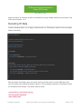
Decoding IR Data
Load the following sketch. It is a slightly modified version of "IRecvDump" sketch from the examples
folder of the library.
#include <IRLib.h>
//Create a receiver object to listen on pin 11
IRrecv My_Receiver(11);
//Create a decoder object
IRdecode My_Decoder;
void setup()
{
Serial.begin(9600);
My_Receiver.enableIRIn(); // Start the receiver
}
void loop() {
//Continuously look for results. When you have them pass them to the decoder
if (My_Receiver.GetResults(&My_Decoder)) {
My_Decoder.decode(); //Decode the data
My_Decoder.DumpResults(); //Show the results on serial monitor
My_Receiver.resume(); //Restart the receiver
}
}
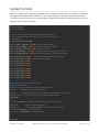
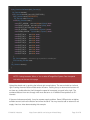
After the sketch has loaded, open your serial monitor and make sure it is set to 9600 baud. Aim
your IR remote at the receiver and press a button. In this example we press the "Play/Pause" button
on the Adafruit Mini Remote. The results were as follows:
Decoded NEC(1): Value:FD807F (32 bits)
Raw samples(68): Gap:40826
Head: m8850 s4450
© Adafruit Industries
https://learn.adafruit.com/using-an-infrared-library
Page 7 of 23
0:m500 s600 1:m550 s550 2:m500 s600 3:m550 s600
4:m500 s600 5:m500 s600 6:m500 s600 7:m550 s550
8:m500 s1750 9:m500 s1700 10:m500 s1700 11:m550 s1650
12:m550 s1700 13:m500 s1700 14:m500 s600 15:m550 s1700
16:m500 s1700 17:m500 s600 18:m500 s600 19:m500 s600
20:m550 s600 21:m450 s650 22:m500 s600 23:m500 s600
24:m500 s600 25:m500 s1700 26:m550 s1700 27:m500 s1700
28:m500 s1700 29:m550 s1700 30:m500 s1700 31:m500 s1700
32:m500
Extent=65850
Mark min:450 max:550
The important part of this dump is the first line. This tells us that the protocol detected was "NEC"
which is protocol number "1" in IRLib's supported protocols. The data value received was the 32-bit
hexadecimal value FD807F. The rest of the information is the raw timing data of the actual marks
and spaces received. That information is useful in trying to understand and supported protocols.
This 32-bit number uniquely identifies the button that you pushed. If we push the Volume down and
Volume up buttons on this remote we would get the values 0xFD00FF and 0xFD40BF.
Try pressing various buttons on a TV or DVD remote you might have lying around the house. If the
top line says:
Decoded Unknown(0): Value:0 (0 bits)
this means that IRLib did not understand the protocol used by your remote. Here are some typical
values from other remotes. I got these from the power button on a Sony DVD player, and the play
button on my Scientific Atlantic DVR/Cable Box.
Decoded Sony(2): Value:74BCA (20 bits)
Decoded Panasonic Old(5): Value:37990C (22 bits)
This shows that the DVD player used Sony protocol which is protocol number 2 and that it is a 20 bit
protocol. The cable box uses Panasonic_Old protocol 5 which is 22 bits. Most protocols always use
the same number of bits however some such as Sony have different versions which could use 8, 12,
or 15 bits in addition to 20.
How It Works
Let's look at what's going on here. The receiver object listens to the IR sensor and when it sees a
signal it starts measuring the timing of the marks and spaces. If a particular amount of time passes
with no additional signals, it presumes that the data is complete and when you call
My_Receiver.GetResults it returns "true". It passes the data to your decoder object. The decoder
© Adafruit Industries
https://learn.adafruit.com/using-an-infrared-library
Page 8 of 23
uses the timing information and the number of bits to see if it matches one of the supported
protocols. If it succeeds, it returns "true" although in this sketch we did not bother to check that first.
You can access the protocol number in My_Decoder.decode_type, the number of bits in
My_Decoder.bits and the the decoded data value in My_Decoder.value.
At the top of the sketch we created the decoder object as type "IRdecode". This is a class which
incorporates all seven of the supported protocols. If you're using the library to control a device such
as a servo or turn relays off and on, you probably are going to be using one remote with one
protocol. Once you know which protocol you are using, you may wish to use a different decoder
class that only works for your particular protocol. It can save valuable program space in your sketch.
For example if we were using the Adafruit Mini Remote which uses NEC protocol would change line
#7 to read:
IRdecodeNEC My_Decoder;
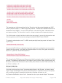
Protocol Specific Issues
IRLib supports 7 protocols directly and includes example code on how to implement 4 others. As
stated earlier, one of the jobs of a library is to isolate the application programmer from the need to
deal with internal issues. However there are some protocol specific things that you may need to deal
with.
The protocols are enumerated in IRLib.h at approximately line 60 as follows.
typedef char IRTYPES; //formerly was an enum
#define UNKNOWN 0
#define NEC 1
#define SONY 2
#define RC5 3
#define RC6 4
#define PANASONIC_OLD 5
#define JVC 6
#define NECX 7
Here are some protocol specific issues you may have to deal with.
NEC Repeat Codes
The NEC protocol uses a special sequence of marks and spaces that mean "I held down the button
so you should repeat whatever I sent you last time". It is up to you to decide do I want to allow
repeat codes or do I want to force the operator to push and release the button each time. IRLib
returns a value of 0xFFFFFFFF to tell you that the special repeat sequence was received. You can
© Adafruit Industries
https://learn.adafruit.com/using-an-infrared-library
Page 9 of 23
ignore that sequence which forces the user to release and repress the button each time or you can
store the previously received code and process it whenever you see the special repeat message.
Sony Triple Messages
The technical specification for Sony protocol says that you should send each code 3 consecutive
times per keypress. IRLib takes care of sending three times for you so you don't need to do
anything special. However when receiving Sony, be aware that you're going to get three copies of
the data each time the user presses a button. If you're busy processing the first sequence you might
miss the other two so it won't matter. But you need to be aware of it in case you're counting the
number of keypresses or some other application.
RC5 and RC6 Toggle Bits
The RC5 and RC6 protocols invented by Phillips use a special toggle bit to let you know whether a
code was generated by holding down the button or whether this is an independent keypress. For
example I have a TV which uses RC5 protocol and the code for Volume Up is 0x1010. If I press and
hold that button it sends the same code repeatedly. However if I release the button and press it
again I get 0x1810. Every other keypress the single bit 0x0800 will toggle off and on. You can make
sure that you ignore this feature by masking out that particular bit. When you receive a decoded
value from this protocol you could do:
My_Decoder.value &=0xf7ff;
This will make sure that the toggle bit is always off. The RC6 protocol also has a title bit which
is 0x10000. Therefore to mask it out you would do:
My_Decoder.value &=0xfeffff;
© Adafruit Industries
https://learn.adafruit.com/using-an-infrared-library
Page 10 of 23
Controlling NeoPixels with IR
In this very simple example we will change the color of a NeoPixel by pushing buttons on the
remote. We are using a single pixel but you can modify the sketch to control an entire strip or
matrix. For more information on NeoPixels visit this guide in the Adafruit Learning
System (http://adafru.it/dYa). Here is the code:
© Adafruit Industries
https://learn.adafruit.com/using-an-infrared-library
Page 11 of 23
#include <Adafruit_NeoPixel.h>
#include <IRLib.h>
IRrecv My_Receiver(11);//receiver on pin 11
IRdecode My_Decoder;//Decoder object
//One NeoPixel connected to pin six
Adafruit_NeoPixel strip = Adafruit_NeoPixel(1,6,NEO_GRB + NEO_KHZ800);
void setup() {
strip.begin();
strip.show(); // Initialize all pixels to 'off'
My_Receiver.enableIRIn(); // Start the receiver
}
void loop() {
if (My_Receiver.GetResults(&My_Decoder)) {
My_Decoder.decode();
if (My_Decoder.decode_type== NEC) {
switch(My_Decoder.value) {
case 0xfd00ff: //Volume Down
strip.setPixelColor(0,255,0,0);//Red
break;
case 0xfd807f: //Play/Pause
strip.setPixelColor(0,0,255,0);//Green
break;
case 0xfd40bf: //Volume Up
strip.setPixelColor(0,0,0,255);//Blue
break;
}
strip.show();
My_Receiver.resume(); //Restart the receiver
}
}
}
We create a NeoPixel strip with one pixel connected to pin 6. Also create a receiver object
connected to pin 11 and a decoder object. Reinitialize the pixel strip and the IR receiver in the setup
routine. Then in the main loop continuously test the receiver to see if it has received many IR
signals. If My_Receiver.GetResults returns true then we decode the data. We are using the Adafruit
Mini Remote we used earlier. It used the NEC protocol so we make sure that we actually received
NEC protocol data. Then we use a switch statement to test various 32-bit hex values against the
decoded data in My_Decoder.value.
After we have set the pixel color based on the received value, we need to call strip.show() to
© Adafruit Industries
https://learn.adafruit.com/using-an-infrared-library
Page 12 of 23
actually change the color and My_Receiver.resume() to reset the receiver so it can collect another
code.
Upload the sketch and try pressing the volume down, play/pause, and volume up buttons. You
should see the pixel change to red, green, or blue. You can easily add additional case statements
and colors or perhaps have one of the cases call an animation routine to animate the entire strip of
pixels. Different buttons on the remote would select different animation patterns.
You will have to modify this sketch if you are using a different remote control. Change the protocol
type spuch as:
if (My_Decoder.decode_type==SONY)
for example if you are using a Sony remote. And of course you have to substitute the proper codes
in each case statement. The enumerated list of available protocols for comparing decode_type can
be found at approximately line 60 of IRLib.h.
© Adafruit Industries
https://learn.adafruit.com/using-an-infrared-library
Page 13 of 23
Controlling a Servo with IR
Setting up the Example
In this example we will control the servo using an IR remote. We can adjust the speed that the servo
moves and we can select individual preset angles for positioning the servo.
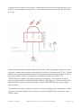
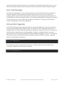
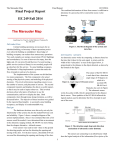
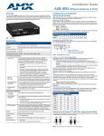
Here is an illustration showing how to wire up the devices. As usual we have an IR receiver
connected to +5v, ground, and pin 11. We also have a servo with three wires. The red wire is +5v.
The black or dark brown wire is ground and the remaining wire usually yellow is the signal wire
which we have connected to pin 9 although it could be any digital output pin.
© Adafruit Industries
https://learn.adafruit.com/using-an-infrared-library
Page 14 of 23
Upload the Code
Below is a version of the IRservo.ino sketch from the IRLib examples folder. It has been modified to
be used with the Adafruit Mini Remote. If you're using a different remote, you will have to collect
information about your codes for various buttons using IRrecvDump and modify the sketch with the
proper protocol name and codes.
#include <IRLib.h>
#include <Servo.h>
// You will have to set these values depending on the protocol
// and remote codes that you are using. These are For the Adafruit
// Mini Remote
#define MY_PROTOCOL NEC
#define RIGHT_ARROW 0xfd50af //Move several clockwise
#define LEFT_ARROW 0xfd10ef //Move servo counterclockwise
#define SELECT_BUTTON 0xfd906f //Center the servo
#define UP_ARROW
0xfda05f //Increased number of degrees servo moves
#define DOWN_ARROW 0xfdb04f //Decrease number of degrees servo moves
#define BUTTON_0 0xfd30cf //Pushing buttons 0-9 moves to fixed positions
#define BUTTON_1 0xfd08f7 // each 20 degrees greater
#define BUTTON_2 0xfd8877
#define BUTTON_3 0xfd48b7
#define BUTTON_4 0xfd28d7
#define BUTTON_5 0xfda857
#define BUTTON_6 0xfd6897
#define BUTTON_7 0xfd18e7
#define BUTTON_8 0xfd9867
#define BUTTON_9 0xfd58a7
IRrecv My_Receiver(11);//Receive on pin 11
IRdecode My_Decoder;
Servo My_Servo; // create servo object to control a servo
int pos;
// variable to store the servo position
int Speed;
// Number of degrees to move each time a left/right button is pressed
long Previous; // Stores previous code to handle NEC repeat codes
void setup()
{
My_Servo.attach(9); // attaches the servo on pin 9 to the servo object
pos = 90;
// start at midpoint 90 degrees
Speed = 3;
// servo moves 3 degrees each time left/right is pushed
My_Servo.write(pos); // Set initial position
My_Receiver.enableIRIn(); // Start the receiver
}
void loop()
© Adafruit Industries
https://learn.adafruit.com/using-an-infrared-library
Page 15 of 23
void loop()
{
if (My_Receiver.GetResults(&My_Decoder)) {
My_Decoder.decode();
if(My_Decoder.decode_type==MY_PROTOCOL) {
if(My_Decoder.value==0xFFFFFFFF)
My_Decoder.value=Previous;
switch(My_Decoder.value) {
case LEFT_ARROW: pos=min(180,pos+Speed); break;
case RIGHT_ARROW: pos=max(0,pos-Speed); break;
case SELECT_BUTTON: pos=90; break;
case UP_ARROW:
Speed=min(10, Speed+1); break;
case DOWN_ARROW: Speed=max(1, Speed-1); break;
case BUTTON_0:
pos=0*20; break;
case BUTTON_1:
pos=1*20; break;
case BUTTON_2:
pos=2*20; break;
case BUTTON_3:
pos=3*20; break;
case BUTTON_4:
pos=4*20; break;
case BUTTON_5:
pos=5*20; break;
case BUTTON_6:
pos=6*20; break;
case BUTTON_7:
pos=7*20; break;
case BUTTON_8:
pos=8*20; break;
case BUTTON_9:
pos=9*20; break;
}
My_Servo.write(pos); // tell servo to go to position in variable 'pos'
Previous=My_Decoder.value;
}
My_Receiver.resume();
}
}
NOTE: If using Leonardo, Micro, or Yun or other ATmega32u4 System, See the special
instructions at the end of this page.
Upload the sketch and try pushing the left and right arrow buttons. The servo should turn left and
right. Pushing the enter button should center the servo. Pushing the up or down arrow buttons will
not have any visible effect but it will change the speed of movement you push left or right. The
numbered buttons from zero through nine move the servo to 10 different fixed positions at 20°
intervals.
If the servo behaves erratically, it may be a power supply problem. Some USB ports do not deliver
sufficient current to drive the Arduino and move the servo. You may need to add an external 5 volt
supply. Here is a video demonstrating this example.
© Adafruit Industries
https://learn.adafruit.com/using-an-infrared-library
Page 16 of 23
How It Works
The program creates a receiver on object, a decoder object and a servo object. You can find more
information on the standard Arduino Servo library here (http://adafru.it/ecQ). The setup function
attaches the servo, enables IR input, and initializes several variables.
The loop function gets an IR code and passes it to a switch statement depending on its value. Each
case of the switch statement handles a different function moving the servo as needed.
There is one bit of overhead we need to take care of because we are using NEC protocol. That
protocol has a unique feature that allows you to see if the button on the remote has been held down
to send repeated instances of the same value. It has a special sequence of marks and spaces that
mean "Repeat what you did last time". When IRLib sees the special sequence, it returns the value
0xFFFFFFFF. We take care of that special case by storing the previous value at the bottom of the
switch statement so that if we get a repeat code we can substitute it the next time. NEC protocol is
the only protocol that uses this particular method for detecting repeat codes. Other protocols have
other systems which are explained in detail in the IRLib documentation.
Special Instructions for ATmega32u4 based systems
The example as presented here should work okay on Arduino Uno or Mega however if you are
using Arduino Leonardo, Arduino Micro, Arduino Yun or other ATmega32u4 based systems, you will
have to make a slight modification to IRLib.
IRLib uses your Arduino's built in hardware timers to generate an interrupt every 50µs so it can poll
the input pin to see if it has changed. By default it uses TIMER2. The Arduino servo library also uses
hardware interrupts using TIMER1. However the ATmega32u4 processor does not have TIMER2 so
IRLib defaults to TIMER1 on systems using that processor. You will have to modify IRLibTimer.h to
change the default timer. In that file at approximately line 70 you will see something like this:
#elif defined(__AVR_ATmega32U4__)
#ifdef CORE_TEENSY
// it's Teensy 2.0
//#define IR_SEND_TIMER1 14
//#define IR_SEND_TIMER3 9
#define IR_SEND_TIMER4_HS 10
#else
/* it's probably Leonardo */
#define IR_SEND_TIMER1 9
//#define IR_SEND_TIMER3 5
//#define IR_SEND_TIMER4_HS 13
#endif
© Adafruit Industries
https://learn.adafruit.com/using-an-infrared-library
Page 17 of 23
You will need to put // in front of #define IR_SEND_TIMER1 to comment out that line. Then remove
the slashes from in front of one of the other two options either TIMER3 or TIMER4_HS. Note that
these defines say "IR_SEND_TIMERxx". Later in the file we copy this value to also be used as the
receiving timer. If you're using Leonardo and you later use IRLib to send IR signals you will need to
make note of the numbers after these defines. Although we can hook a receiver to any digital input
pin, IRLib requires you to use specific output pins depending on which timer you are using. Will
cover that later in the section on sending.
© Adafruit Industries
https://learn.adafruit.com/using-an-infrared-library
Page 18 of 23
Sending IR Codes
Hardware Issues
IRLib not only receives and decodes IR signals but it can transmit them as well using an IR LED and
a driver circuit. The library has been used to control TVs, cable boxes, DVDs, VCRs, and IR
controlled toys such as helicopters and dinosaur robots.
It could also be used to control some home automation devices. Some users have attempted to
© Adafruit Industries
https://learn.adafruit.com/using-an-infrared-library
Page 19 of 23
control air conditioners and fans however protocols used for air-conditioners are extremely difficult
to implement and we have not directly supported such protocols because they are very rare.
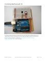
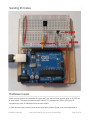
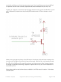
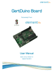
Typically the output pin of an Arduino cannot supply sufficient current to drive and IR LED so you will
want to implement a simple driver circuit using NPN transistor and a 470 ohm resistor is shown
here:
Make sure that you get the polarity of the LED correct. The shorter of the two leads connects to the
transistor and the longer one connects to the positive supply. Note that the current passing through
the LED will in all likelihood will exceed the maximum continuous current rating. However because
the signal is modulated and sending a sequence of pulses that will only last a few milliseconds the
circuit will work fine.
More advanced driver circuit schematics are available in the IRLib manual in section 1.4 Hardware
Considerations.
© Adafruit Industries
https://learn.adafruit.com/using-an-infrared-library
Page 20 of 23
While we can connect an IR receiver to any available digital input pin, you can only use very specific
pins for output. The library uses PWM pins and modifies the timing parameters to change the
default frequency of that pin.
The default timer is TIMER2 on the Arduino Uno and Arduino Mega. On the Leonardo with is
TIMER1. The pin numbers are pin 3 for Uno and use pin 9 for the Leonardo and Mega. If you have
modified the library to use a different timer such as changing the timer number on a Leonardo to
avoid conflicts with the servo library, then you will need to use a different specific pin. See section
1.4.1 Supported Platforms in the IRLib users manual for a table which shows the relationship
between hardware timers and pin numbers.
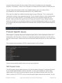
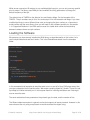
Loading the Software
We presume you have already installed the IRLib library as described earlier in this tutorial. Let's
load a simple sketch and see how it works. This is the IRsendDemo sketch from the examples
folder.
#include <IRLib.h>
IRsend My_Sender;
void setup()
{
Serial.begin(9600);
}
void loop() {
if (Serial.read() != -1) {
//send a code every time a character is received from the serial port
//Sony DVD power A8BCA
My_Sender.send(SONY,0xa8bca, 20);
}
}
In this somewhat trivial example we send the code to turn on and off a Sony DVD player every time
you type a character into the serial monitor. We create a sending object My_Sender. There is no set
up except to initialize the serial port. In the loop we check for incoming characters and if we've got
one we send the code.
The send method has three parameters: the protocol type, the data, and the number of bits.
The IRsend object we created is a generic routine that supports all seven protocols. However in this
case since we are only using one protocol we could've created the object using:
© Adafruit Industries
https://learn.adafruit.com/using-an-infrared-library
Page 21 of 23
IRsendSony My_Sender;
Inside the loop the send command would then be:
My_Sender.send(0xa8bca, 20);
Some protocols such as NEC always use the same number of bits and so you do not need to
specify as an additional parameter. See the prototypes in IRLib.h and the users manual to see if the
extra bits parameter is required.
Sending and Receiving in the Same Program
There are special considerations when doing sending and receiving in the same program. Both
sending and receiving make use of the building hardware timers. However the timer is used for two
different purposes. When you send a code, it reconfigures the timer and disables receiving. So you
have to reenable your receiver after each send. For example:
My_Sender.send(Protocol, Data, Bits);
My_Receiver.enableIRIn(); // Re-enable receiver
Normally you would only need to call My_Receiver.enableIRIn(); once in the setup routine but if
you are both sending and receiving you have to call it after each send.
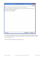
For a complete example of how to send and receive in the same program, look at the IRrecord.ino
sample sketch in the examples folder. When you load the sketch, open your serial monitor, point a
remote at the receiver and push a button. The program will capture that code. Then every time the
type of character into the serial monitor it will repeat that code through the LED.
© Adafruit Industries
https://learn.adafruit.com/using-an-infrared-library
Page 22 of 23
In a separate tutorial we will show you how to use IRLib to create your own universal remote by
either sending data through the serial port into the Arduino or by creating a web-based universal
remote using Arduino Yun.
All photos, videos and wiring courtesy Kenneth Young
© Adafruit Industries
Last Updated: 2015-02-26 05:00:06 PM EST
Page 23 of 23