1
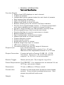
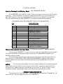
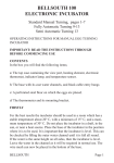
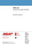
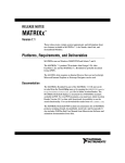
PRECEPT 12 LIGHTING CONTROL DESK USER MANUAL 2ND Edition 1987 INDEX 1. GENERAL INFORMATION. PAGE Introduction ……………………………………………………………………………….3 Technical Specification ………………………………………………………………..4 2. OPERATING INSTRUCTIONS. The Layout of the Desk Using the Precept 12 as a 2 ………………………5 Preset Manual Desk ……………………………………………………………………..6 Programming a Scene …………………………………………………………………7 Playing Back a Pre – Recorded Scene…………………………………………….8 Recording a New Scene from a Combination of Two or More Existing Scenes……………………………………………………………………………9 Blind Programming……………………………………………………………………10 Some Notes On Programming……………………………………………………..11 The Preview Function…………………………………………………………………12 The Solo Buttons………………………………………………………………………..13 The ‘Add’ Solo Button Function…………………………………………………..14 The ‘Kill’ Solo Button Function…………………………………………………….15 The Chase Function…………………………………………………………………….16 Programming the Sequence……………………………………………………….17 Running the Chaser…………………………………………………………………….18 INDEX 3. INSTALLATION. PAGE How to connect the Dimmer Rack ………………………………………………19 Power Requirements ………………………………………………………………….19 Control Voltage Adjustment………………………………………………………..20 Set up Procedure……………………………………………………………………….20 Connecting to the Remote Input Jack …………………………………………21 4. MAINTENANCE. Safety and Protection …………………………………………………………………22 Looking after the PRECEPT …………………………………………………………22 Spare Parts List ……………………………………………………………………………. 1. GENERAL INFORMATION Introduction Congratulations on your purchase of the PRECEPT Lighting Control Desk. The PRECEPT combines a powerful microcomputer and superb ergonomics with the same high quality components and drive circuitry as used in all of LSC’s range of Lighting control desks. The Precept offers the user a 12 channel two preset desk with all the quality, simplicity and facilities of a professional manual desk, together with programmable scene and chaser functions that up until now could only be found on desks three times as expensive. Considerable thought has gone into the positioning and grouping of the PRECEPT’s various controls which, together with it’s advanced features and modern slimline appearance, make it a pleasure to use. The PRECEPT has the ability to get the absolute maximum performance from a twelve channel Lighting rig and is thus the ideal desk for bands, small theatre groups, schools, discos and audio visual displays. 1. GENERAL INFORMATION Technical Specification Function Details • Output level LED displays on each channel. • 2 banks of presets. • Independent group master faders for each bank of presets. • Solo buttons over all faders. • Add / Kill facilities on all solos. • Master level fader on solo intensity. • Bottom preset group can function as Scene masters. • 24 fully level programmable scenes. (12 Scenes associated with scene masters and 12 with the chase function.) • Dynamic range divided into 256 possible intensity levels. • Blind programming of both scenes and chaser. • Preview facilities to cue the next scene or chaser. • Battery backed up memory. • One hundred step, twelve-scene chaser. • Master level fader on chaser intensity. • Chaser direction control. • Chaser speed control. • Single step control on chaser. • Remote single step input on chaser. • LED mimic display for chaser. • Connects directly into the LSC range of dimmers. Output Level 0 to +0 volt nominal. Optional negative drive version 0 to –10 volts Maximum level adjustable between 5 to 10 volts Output Connection 2 meter tail with a Cannon 3106E 20 – 27 PB Connector. Pins A to J, M, and N are channel outputs 1 to 12; Pin L is not connected. Remote Trigger Stereo phone jack. (Tip is signal, ring is 0v) Power Requirements The PRECEPT 12 is supplied with an external 18 volt AC Plug – pak power supply. Dimensions 70 mm x 485mm x 375mm overall Construction Chassis is mild sheet steel finished in black baked enamel. Cover is black anodized aluminum. End pieces are polished hard wood. Weight 5 kg. 2. OPERATING INSTRUCTIONS THE LAYOUT OF THE DESK. 1. MODE SWITCH 9. MASTER BUTTONS 2. FLASH BUTTON CONTROL SWITCH 3. OUTPUT DISPLAY 10. SOLO MASTER 11. CHASER MASTER 4. YELLOW FADER BANK 12. SINGLE SPEED CONTROL 5. RED BANK/ SCENE MASTER FADERS 6. RED MASTER 13. SINGLE STEP 7. YELLOW MASTER 15. DIRECTION/ SEQUENCE BUTTON 16. CHASER MIMIC 8. CHANNEL BUTTONS 14. REMOTE INPUT JACK 2. OPERATING INSTRUCTIONS USING THE PRECEPT 12 AS A 2 PRESENT MANUAL DESK 1. Turn the MODE SWITCH to PRESET. 2. The SOLO BUTTON CONTROL SWITCH should be in ADD or KILL BUT NOT PREVIEW 3. Bring up some channel faders on the YELLOW BANK. 4. Bring up some different channel faders on the RED BANK. 5. Bring up the YELLOW MASTER fader. The channels selected on the YELLOW BANK will fade up on stage. The OUTPUT DISPLAY will mimic this. 6. To cross fade bring down the YELLOW MASTER fader. The first preset of lights will fade down and the second preset – those channels selected on the RED BANK – will fade up. The OUTPUT DISPLAY will mimic this. RETURN ALL FADERS TO 0 BEFORE CARRYING ON TO THE NEXT STEP. 3. OPERATING INSTRUCTIONS PROGRAMMING A SCENE. There are several ways of Programming (Recording) a Scene. This first method is the simplest. It reduces you to bring up the lights onstage and when you are happy with the results to record them. It can be done by using the YELLOW or RED BANK of faders. 1. Turn the MODE SWITCH to PRESET. 2. The SOLO BUTTON CONTROL SWITCH should be in ADD or KILL but NOT PREVEIW. 3. Bring up the YELLOW MASTER fader. 4. Bring up some cannel faders on the YELLOW BANK until you have light levels set up as required. 5. Select the PROGRAM position on the MODE SWITCH. 6. Press any of the twelve CHANNEL BUTTONS. For the sake of this exercise let us assume that you press the CHANNEL BUTTON beneath Red Fader number 1. (Notice that the CHASER MIMIC LED’s flash once rapidly from left to right). You may now go on to record more scenes of you wish pressing a different CHANNEL BUTTON each time. 7. As soon as you have finished programming scenes remember to switch the MODE SWITCH out of the PROGRAM position. RETURN ALL FADERS TO 0 BEFORE CARRYING ON TO THE NEXT STEP. 2. OPERATING INSTRUCTIONS PLAYING BACK A PRE – RECORDED SCENE. 1. Turn the MODE to SCENE. The RED BANK will now act as SCENE MASTER. 2. The SOLO BUTTON CONTROL SWITCH should be in ADD or KILL but NOT REVIEW. 3. Bring up the RED MASTER fader. 4. Bring up Red fader number 1. The scene that you previously recorded by pressing the CHANNEL BUTTON beneath that fader will now be reproduced on stage. The OUTPUT DISPLAY will mimic this. NOTE: When you select the SCENE position on the MODE SWITCH as you have seen the RED BANK will become SCENE MASTERS however the YELLOW BANK will continue to respond as it did in PRESENT MODE. RETURN ALL FADERS TO 0 BEFORE CARRYING ON TO THE NEXT STEP. 2. OPERATING INSTRUCTIONS RECORDING A NEW SCENE FROM TWO OR MORE EXISTING SECENES. A useful rule to remember is that if you have lights on stage, regardless of how they got there, they can be recorded as a scene. The method outlined below shows how to record a new scene by coming two or more pre-recorded scenes. 1. Turn the MODE SWITCH to SCENE. 2. The SOLO BUTTON CONTROL SWITCH should be in ADD or KILL but NOT PREVIEW. 3. Bring up the RED MASTER fader. 4. Bring up the two or more faders on the RED BANK which already contain pre-recorded scenes. For the sake of this exercise we will assume that you bring up faders number 1 & 2. The lights on stage will be a combination of these two scenes. 5. Turn the MODE SWITCH to PROGRAM. 6. Press a CHANNEL BUTTON to record the new scene. Let us assume you press the CHANNEL BUTTON beneath RED BANK fader number 3. The CHASE MIMIC will flash once rapidly from left to right. 7. Turn the MODE SWITCH from PROGRAM to SCENE. Bring up the RED MASTER and RED BANK fader number 3 to playback the new scene. NOTE: Had you wished you could have added extra channels from the YELLOW BANK to help build up the new scene. RETURN ALL FADERS TO 0 BEFORE CARRYING ON THE NEXT STEP. ‘BLIND’ PROGRAMMING. From time to time you may find it necessary to program a scene without having lights come on stage. For example during a performance you may be playing back on scene while programming another. This is called blind programming. 1. Turn the MODE SWITCH to PRESET. 2. The SOLO BUTTON CONTROL SWITCH should be in ADD or KILL but NOT PREVIEW. 3. Leaving the YELLOW MASTER at 0 bring up some channels on the YELLOW BANK. 4. Turn the MODE SWITCH to PROGRAM. 5. While holding down the YELLOW SOLO MASTER BUTTON ….. 6. Press the desired CHANNEL BUTTON. The SCENE MASTER above this Button now stores the scene set up on the YELLOW BANK. 7. As soon as you have finished programming, REMEMBER to switch the MODE SWITCH out of the PROGRAM position. RETURN ALL FADERS TO 0 BEFORE CARRYING ON TO THE NEXT STEP. NOTE: Had you wished this process could have been carried out while a scene was on stage? In this case SCENE MODE would have been selected in step 1. BLIND programming can be carried out from the RED or YELLOW FADER BANK and in PRESENT or SCENE MODE. SOME NOTES ON PROGRAMMING We have seen with the ‘blind’ programming function that it is possible to program the desk and operate it at the same time. Please note that when you have selected the PROGRAM position on the MODE SWITCH the desk is also in either PRESET or SCENE. If it was in PRESET it will stay in PRESET, if it was in SCENE it will stay in SCENE. This can take a little getting used to. Try this as and exercise. Record a scene onto Scene Maser number 1. Turn the MODE SWITCH to PRESET. Bring up RED BANK FADER number 1 and the RED MASTER. The OUTPUT DISPLAY will show you that you only have one channel on stage. Turn to the PROGRAM position. Nothing happens; you still have one channel on stage. Turn back to the SCENE position. Now you have Scene 1 on stage. Turn back to the PROGRAM position Scene 1 is still on stage. *** If you have recorded a scene for playback on, for example, RED BANK fader number 1 and it is no longer required you may record another scene on top of it. This will cancel the old scene and replace it with the new. Before starting a new production some people prefer to clear all preciously recorded scenes from the desk. This can easily be done. In effect you program in nothing. Making sure all faders are down and there are no lights on stage. Select the PROGRAM position on the MODE SWITCH. Press all the CHANNEL BUTTONS one after the other. The desk will now be clear. Switch out of PROGRAM MODE before continuing. (If you forget to do this you may accidentally record over a scene!). *** It is also useful to remember that a battery backs the memory of the desk– up. If the desk is disconnected from the power supply it will maintain its memory for 2 – 4 weeks. No harm can come to the desk by leaving it plugged in and switched on. THE PREVIEW FUNCTION. From time to time you may want to check on the contents of a prerecorded scene. Obviously this can be done by bringing the lights up on stage. This is not a suitable procedure in the middle of a performance. The PREVIEW function allows you to use are playing back another scene. In the example below Scene 1 is on stage, Scene 2 will be previewed. 1. Turn the MODE SWITCH to SCENE. 2. Bring up the RED MASTER. 3. Bring up RED BANK fader number 1. The OUTPUT DISPLAY will mimic the scene on stage. 4. Turn the SOLO BUTTON CONTROL SWITCH to PREVIEW. 5. Press CHANNEL BUTTON number 2. The OUTPUT DISPLAY for Scene 1 will go out and be replaced by the OUTPUT DISPLAY for Scene 2 but the lights on stage will not change. 6. When you have finished Previewing it is important to remember to turn The SOLO BUTTON SWITCH to ADD or KILL. RETURN ALL FADERS TO 0 BEFORE CARRYING ON TO THE NEXT STEP. THE SOLO BUTTONS. So far we have used the CHANNEL BUTTONS for two different functions. Firstly in the process of recording a scene, secondly for Previewing recorded scenes. There is a third use of these buttons which relates to the operation of the desk during a performance. The CHANNEL BUTTONS can be used as Solo Buttons (another common name is Flash Buttons). This can be done in Preset or Scene Mode. In Preset Mode they will flash a single channel; in Scene Mode they will flash the entire scene. This Solo Button describes the ADD function. For the sake of this exercise, record channels 1 and 2 at Full as Scene 1 and channels 3 to 12 at Full as Scene 2. THE ‘ADD’ SOLO BUTTON FUNCTION. 1. Turn the MODE SWITCH to SCENE. 2. Bring up the RED MASTER. 3. Bring up Red bank FADER NUMBER 1. The OUTPUT DISPLAY will mimic the scene on stage (channels 1 & 2). 4. Turn the SOLO BUTTON CONTROL SWITCH to ADD. 5. Bring up the SOLO MASTER. 6. Press CHANNEL BUTTON number 2. As long as you hold your finger on this button Scene 2 will come on stage. Scene 1 is not affected. RETURN ALL FADERS TO 0 BEFORE CARRYING ON TO THE NEXT STEP. NOTE: The SOLO MASTER allows you to set an overall level for any scene or channel being controlled via a SOLO BUTTON. It is called the ADD function because it allows you to use the SOLO BUTTONS to add a scene or channel to the output of the desk. If you wish you may also use the MASTER BUTTONS as SOLO BUTTONS. In this case the contents of the relevant Fader Bank will flash on stage. To see how this works, bring up some channels on the YELLOW BANK with the YELLOW MASTER at 0. Bring up the SOLO MASTER then press the YELLOW MASTER BUTTON. The scene set up on the YELLOW BANK will flash on stage. The same effect would be achieved if you had used the RED BANK but noticed the different results when you have the MODE SWITCH in PRESET compared to SCENE. THE ‘KILL’ SOLO BUTTON FUNCTION. Having seen how ADD function works repeat the process but this time select the KILL position of the SOLO BUTTON CONTROL SWITCH. The effect will best be seen if we bring up Scene 2 on stage and press CHANNEL BUTTON number 1. 1. Turn the MODE SWITCH to SCENE. 2. Bring up RED MASTER. 3. Bring up RED BANK fader number2. The OUTPUT DISPLAY will mimic the scene on stage (channels3 to 12). 4. Turn the SOLO BUTTON CONTROL SWITCH to KILL. 5. Bring up the SOLO MASTER. 6. Press CHANNEL BUTTON number 1. As long as you hold your finger on this button Scene 1 will come on stage and all other output from the desk will be extinguished (killed). RETURN ALL FADERS TO 0 BEFORE CARRYING ON TO THE NEXT STEP. NOTE: The KILL function can be used to give a Direct Black Out (D.B.O.). If the SOLO MASTER is at 0 and the SOLO BUTTON CONTROL SWITCH is in the KILL position any SOLO BUTTON can be used to obtain a blackout. THE CHASE FUNCTION. The PRECEPT 12 allows you to record 12 scenes to be played back via the Scene Master (the RED BANK). It also allows you to record another 12 scenes to be used with the Chase Function. Chase Scenes are recorded in the normal way except that the CHASE MASTER SOLO BUTTON is held down to indicate that a chase scene is being programmed. Described below is the simplest method but please note that you can use any of the methods of recording a scene described earlier (e.g. ‘blind programming’) to record a Chase Scene as long as you hold down the CHASE MASTER SOLO BUTTON. 1. The MODE SWITCH should be in the PRESET position. 2. The SOLO BUTTON CONTROL SWITCH should be in ADD or KILL but NOT PREVIEW. 3. Bring up the YELLOW MASTER fader. 4. Bring up some channel faders on the YELLOW BANK until you have light levels set up as required. 5. Select the PROGRAM position on the MODE SWITCH. 6. While holding the CHASE MASTER SOLO BUTTONS…….. 7. Press any of the twelve CHANNEL BUTTONS. Repeat the process to record more CHASE SCENES. 8. As soon as you have finished programming remember to switch the MODE SWITCH out of the PROGRAM position. RETURN ALL FADERS TO 0 BEFORE CARRYING ON TO THE NEXT STEP. PROGRAMMING THE SEQUENCE. Having recorded up to 12 Chase Scenes next you need to program the order in which you want them to appear. The order in which the Scenes appear is called the Sequence. It is not necessary to use all 12 Chase Scenes and you may, if you wish, use any Chase Scene more than once. A sequence is made up of a number of steps. The maximum number of steps permitted by the PERCEPT 12 is100. Described below is the method of programming a four-step sequence. It will be necessary to record four Chase Scenes. 1. The SOLO BUTTON CONTROL SWITCH should be in ADD or KILL but NOT PREVIEW. 2. Select the PROGRAM position on the MODE SWITCH. 3. While holding down the DIRECTION/ SEQUENCE BUTTON……. 4. Press CHANNEL BUTTON 1, then CHANNEL BUTTON 2, then CHANNEL BUTTON 3, then CHANNEL BUTTON 4. 5. As soon as you have finished programming remember to switch the MODE SWITCH out of the PROGRAM position. RETURN ALLL FADERS TO 0 BEFORE CARRYING ON TO THE NEXT STEP. RUNNING THE CHASER. Having programmed the Chase Scenes and the sequence you can now run the chase. 1. Bring up the CHAASE MASTER fader. 2. Bring up the CHASE SPEED CONTROL. NOTE: The CHASER MIMIC will tell you, which Chase Scene is in use, and the OUTPUTDISPLAY which channels are appearing on stage. You may run the Chase while using other functions of the desk. When the CHASE is running you may reverse the order of the sequence by holding down the DIRECTION/ SEQUENCE BUTTON. When the CHASE SPPED CONTROL is at 0 you may use the SINGLE STEP BUTTON. Each time you press it the sequence advances by one step. An external trigger may also be use to duplicate the functions of the SINGLE STEP BUTTON by connecting into the REMOTE JACK INPUT on the back of the desk. 3. INSTALLATION How to Connect the Dimmer Rack – LSC DIMMER RACKS. The PERCEPT provides a 14 pin Cannon plug on the end of a 2 metre long tail. This connector is directly compatible with the input socket on any LSC dimmer rack and therefore the two may be directly connected. The pin definitions for the PRECEPT’s output connector are below. PIN DEFINITION OF PRECEPT OUTPUT CONNECTOR DESCRIPTION PIN A B C D E F G H I J K L M N Channel 1 output. Channel 2 output. Channel 3 output. Channel 4 output. Channel 5 output. Channel 6 output. Channel 7 output. Channel 8 output. Channel 9 output. Channel 10 output. COMMON 0V (earth). Not connected. Channel 11 output. Channel 12 output. How to connect the Dimmer Rack – OTHER MANUFACTURERS RACKS Connecting PRECEPT to most of the currently available dimmer racks on the Australian marked is made simply by its adjustable output and flexible power needs. Provided that the dimmer can accept the input signals described in the section on CONTROL VOLTAGE ADJUSTMENT overleaf then only a linking cable that correctly connects the pins as outlined above will be required. NOTE: To minimize the effect of long control cables it is recommended that good quality cable containing a heavy earth shield is used and that this and any spare lines be connected to the two ‘K’ pins to from a low resistance earth resistance earth path between dimmer and desk. POWER REQUIREMENTS The power for the PRECEPT is provided by an external Plugpak of 18 volts AC @ 1 Amp supplied with your PRECEPT. 3. INSTALLATION Control Voltage Adjustment. The PRECEPT output voltage is factory set for a +10 volt maximum control voltage however, this is adjustable between +15V to +10V. The output voltage range is adjusted by a slotted rotary control accessed from the bottom of the PRECEPT as shown in fig. 4. This adjustment should be done with a small screwdriver (ref. 3.5 set up Procedure). 1.Ensure that the dimmer rack accepts the same polarity signals as your PRECEPT and that it is correctly connected. SET ALL FADES TO THE ZERO (0) position, switch the MODE SWITCH to the PRESET position. Connect the PLUG – PAK and turn on power. The LED indicators beside the MODE SWITCH should be glowing. If not, check that the PLUG – PAK is correctly connected and turned on. Apply power to the dimmer. 2. With a suitable lamp connected to one of the dimmer channels, raise the corresponding YELLOW CHANNEL fader and YELLOW MASTER FADER of the desk to the full on position. If the dimmer is the correct polarity and uses a 10-volt maximum signal (as do the LSC racks) then the land should correctly light up to full intensity. All PRECEPTS are factory set for a 10 volt maximum. Provided that the lamp has come onto full intensity and that by lowering the channel fader it can be smoothly dimmer then the desk is ready for use. If the lamp fails to glow or cannot be dimmed, check that the correct power output polarity and levels have been met. If no error can be found then contact qualified personnel. If the lamp does not reach its full intensity or does not dim over the full range of the fader then continue on with the adjustment below. 3. With the power still connected, lift the PRECEPT up gain access to the Output level MAX ADJUST slot (ref. Fig.4) and rotate this until the maximum output brightness is just achieved at the maximum fader position. The PRECEPT is now ready for use. CONNECTING TO THE REMOTE INPUT JACKS. To single step the Chaser via the REMOTE INPUT the PRECEPT expects the signal line on the tip of the phone plug to be switched to the 0 volt line on the ring of the plug. The PRECEPT detects the closing action of any foot or pressure switch connected between these two lines. For the operator who wishes to connect a control signal directly to the PRECEPT the actual switching voltage level is approximately 2 volts. The control signal must therefore fall cleanly from above 4 volts to below 0.5 volts to ensure a reliable single step trigger. Such a control signal should not exceed +20 volts relative to the ground of the PRECEPT i.e. the ring connector. REMOTE IMPUT SPECIFICATION. * Stereo phono jack. * Signal Type. Tip connection – signal line. Ring connection – 0V signal ground line. Case connection – Shield ground. Detects falling edge. Threshold at 2 volts. Maximum signal +20 volts. 4. MAINTENCNCE Safety and Protection The PRECEPT uses no high voltages and unless the dimmer racks have been grossly misconnected there is no danger of electrocution. The PERCEPT’s internal electronics is protected by a 1 Amp Slow – blow fuse located inside the desk on the PCB. Whilst this fuse should not need replacing under normal circumstances, it is essential that if it is replaced, it is only replaced with a similar one having 1 Amp rating. For inspection of this fuse only the left timber end need be removed since the fuse is mounted at the top left corner of the PRECEPT. Looking after the PRECEPT. The PRECEPT is a rugged piece of electronics designed to cope with a moderate amount of hard living, however it is still vulnerable to constant misuse and neglect. Always observe the following: DO NOT DROP FOOD, DRINK OR ANY OTHER LIQUID ONTO THE DESK! If a drink or other corrosive liquid is spilt over the desk and into the faders then the PRECEPT should be internally cleaned and dried AS SOON AS POSSIBLE. Note that only experienced personnel should attempt this type of maintenance. Do not apply excess force on any of the controls. Spare parts and service are available, but prevention is better than cure (and cheaper too!) Do not apply excess force on any of the controls. Spare parts and service are available, but prevention is better than cure (and cheaper!) If the desk is to be used “on the road” then an appropriate protection road case should be obtained. When connecting up dimmers or remote inputs etc. make sure that it has been done correctly BEFORE applying power. If any doubt exists about what is correct then obtain assistance from qualified personnel. To clean the metal surface and labeling of the desk a little Methylated Spirits can be used.