1
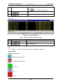
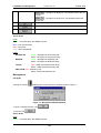
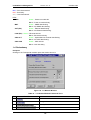
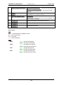
MegaVision
LambdaDriver Management
User Guide
MRV Communications, Inc.
URL: http://www.mrv.com
LambdaDriver Management
ML46661, Rev. 02
October 2004
Disclaimer
®
MRV reserves the right to modify the management application for this device at any time and in any way it
sees fit in order to improve it.
MRV provides this document without any warranty of any kind, either expressed or implied, including, but
not limited to, the implied warranties of merchantability or fitness for a particular purpose.
The user is advised to exercise due discretion in the use of the contents of this document since
the user bears sole responsibility.
Trademarks
All trademarks are the property of their respective holders.
Copyright © 2001 by MRV
All rights reserved. No part of this document may be reproduced without the prior permission of MRV.
This document and the information contained herein are proprietary to MRV and are furnished to the
recipient solely for use in operating, maintaining and repairing MRV equipment. The information within may
not be utilized for any purpose except as stated herein, and may not be disclosed to third parties without
written permission from MRV. MRV reserves the right to make changes to any technical specifications in
order to improve reliability, function, or design.
Document Number: ML46661
Document Revision: Rev. 02
Contact Information
For customer support, you can:
Contact your local MRV representative
E-mail us at [email protected]
Visit our MRV Web site at http://www.mrv.com
2
Release Date: October 2004
LambdaDriver Management
ML46661, Rev. 02
October 2004
Contents
About this Guide ............................................................................... 5
Scope ..........................................................................................................................................5
Audience ....................................................................................................................................5
Related Documents ...................................................................................................................5
Organization...............................................................................................................................5
Typographical Conventions .....................................................................................................5
Acronyms ...................................................................................................................................6
LambdaDriver Overview................................................................... 7
General .......................................................................................................................................7
Components...............................................................................................................................7
Chassis...................................................................................................................................7
Mux Module ............................................................................................................................7
Demux Module .......................................................................................................................7
Transponder Module ..............................................................................................................7
Management Module..............................................................................................................7
Service Module.......................................................................................................................8
1+1 Redundancy Module .......................................................................................................8
OADM Module ........................................................................................................................8
Power Supply Module ............................................................................................................8
Redundant Power Supply Module..........................................................................................8
Device Channels........................................................................................................................8
CWDM ....................................................................................................................................8
DWDM ....................................................................................................................................8
Management ...................................................................................... 9
General .......................................................................................................................................9
Hot Spots................................................................................................................................9
Active Areas ...........................................................................................................................9
Access ........................................................................................................................................9
Map level ..................................................................................................................................10
Hot Spots & Active Areas .....................................................................................................10
Adding an LambdaDriver......................................................................................................10
Device Level.............................................................................................................................11
Hot Spots..............................................................................................................................12
Active Areas .........................................................................................................................28
Power Supply .......................................................................................................................29
Transponder .........................................................................................................................29
Management ........................................................................................................................30
3
LambdaDriver Management
ML46661, Rev. 02
October 2004
1+1 Redundancy ..................................................................................................................31
Software Upgrading/Downloading.................................................33
General .....................................................................................................................................33
Requirements...........................................................................................................................33
Procedure .................................................................................................................................33
Glossary ...........................................................................................34
Figures
Figure 1: Login Window .................................................................................................................. 9
Figure 2: Map Level Window ........................................................................................................ 10
Figure 3: Device Zoom Window ................................................................................................... 11
Figure 4: Device Configuration Window ....................................................................................... 12
Figure 5: Device Information Window........................................................................................... 15
Figure 6: Ping Window.................................................................................................................. 16
Figure 7: Warm Reset Window..................................................................................................... 16
Figure 8: Cold Reset Window....................................................................................................... 16
Figure 9: Initialize NVRAM Window.............................................................................................. 17
Figure 10: Reset Statistics Window.............................................................................................. 17
Figure 11: Describe Window ........................................................................................................ 17
Figure 12: Identify Window ........................................................................................................... 20
Figure 13: ARP Table Window ..................................................................................................... 21
Figure 14: Interfaces Table Window............................................................................................. 23
Figure 15: Alarm Log Window ...................................................................................................... 28
Figure 16: Transponder Module Window ..................................................................................... 29
Figure 17: Management Module Window..................................................................................... 30
Figure 18: 1+1 Module Window.................................................................................................... 31
Tables
Table 1: Device Configuration Window Fields and Tools............................................................. 12
Table 2: Device Information Window Fields and Tools ................................................................ 15
Table 3: Ping Window Fields and Tools ....................................................................................... 16
Table 4: Describe Window Fields and Tools ................................................................................ 18
Table 5: Identify Window Fields and Tools................................................................................... 20
Table 6: ARP Table Window Fields and Tools............................................................................. 21
Table 7: Interfaces Table Window Fields and Tools .................................................................... 23
Table 8: Alarm Log Window Fields and Tools.............................................................................. 28
Table 9: Transponder Module Window Fields and Tools ............................................................. 29
Table 10: 1+1 Module Window Fields and Tools ......................................................................... 31
4
LambdaDriver Management
ML46661, Rev. 02
October 2004
About this Guide
Scope
This guide shows how to manage any of the series of LambdaDrivers (e.g., LambdaDriver 400,
LambdaDriver 800, LambdaDriver 1600) using MRV’s MegaVision® network management
application.
Audience
This guide is intended for the use of network administrators who have working knowledge of
SNMP management.
Related Documents
• MegaVision NMS Application User Manual
This manual describes how to install and use the MRV’s MegaVision NMS Application.
• MegaVision LambdaDriver Release Notes
This document contains information not found in the User Guide and/or overriding
information, and is produced if warranted.
Organization
For customer convenience, the management description is organized according to the service
architecture of the MegaVision Application GUI which is hierarchical. Accordingly, management is
described on the following four levels:
Map level – The LambdaDriver is represented by an identifying icon in the network map and is
manageable as a network element.
Device level – The LambdaDriver is represented by an identifying live image and is manageable
as a single entity.
Module level – A module of the LambdaDriver is represented by an identifying live image and is
managed as an individual entity.
Port level – A module port of the LambdaDriver is represented by an identifying live image and is
managed as an individual entity.
Typographical Conventions
The typographical conventions used in this document are as follows:
Convention
Explanation
CourierBold
This typeface represents information provided by/to the system.
Italics
This typeface is used for emphasis.
Enter
This format represents the key name on the keyboard or keypad.
L
This icon represents important information.
This icon represents risk of personal injury, data loss, or system damage.
5
LambdaDriver Management
ML46661, Rev. 02
Acronyms
ARP
Address Resolution Protocol
ATM
Asynchronous Transfer Mode
BER
Bit-Error Rate
CLI
Command Line Interpreter
CTS
Clear To Send
CWDM
Coarse Wavelength-Division Multiplexing
dB
deciBel
DCD
Data Carrier Detect
DNS
Domain Name System/Service
DSR
Data Set Ready
DTR
Data Terminal Ready
DWDM
Dense Wavelength-Division Multiplexing
Gnd
Ground
GUI
Graphical User Interface
IP
Internet Protocol
ISP
Internet Service Provider
ITU
International Telecommunications Union
LAN
Local Area Network
MAN
Metropolitan Area Network
MDI
Media Dependent Interface
MDI-X
Media Dependent Interface with cross-wiring
NMS
Network Management Station
OA
Optical Amplifier
OADM
Optical Add-Drop Multiplexer
OID
Object IDentifier
OSC
Optical Service Channel
RARP
Reverse ARP
RI
Ring Ignore
RMON
Remote MONitoring
RTS
Request To Send
RxD
Receive Data
SDH
SNMP
Synchronous Digital Hierarchy
Simple Network-Management Protocol
SONET
Synchronous Optical Network
TDM
Time-Division Multiplexer/Multiplexing
TELNET
(dial-up) TELephone NETwork (connection protocol)
TFTP
Trivial-File Transfer Protocol
TxD
UPS
URL
WAN
WDM
Transmit Data
Uninterruptible Power Supply
Universal Resource Location
Wide Area Network
Wavelength-Division Multiplexing
6
October 2004
LambdaDriver Management
ML46661, Rev. 02
October 2004
LambdaDriver Overview
General
The LambdaDriver is a multi-functional modular wavelength-division multiplexer that can operate
in DWDM and CWDM modes. Model 400 can create as many as four virtual fibers (channels1) on
a single physical fiber. Model 800 can create as many as eight virtual fibers on a single physical
fiber. Model 1600 can create as many as sixteen virtual fibers on a single physical fiber. Each
virtual fiber is fully independent of the others and can carry data at the same rate as a physical
fiber.
LambdaDriver is architectured as a scalable system that can be expanded and enhanced simply
by inserting pluggable modules.
The basic LambdaDriver consists of a chassis and the following modules: Mux and Demux (1
each) or OADM (1); Transponders (1 per virtual fiber); Power Supply (1).
LambdaDriver can be scaled up by inserting the following modules: Additional Transponders (up
to 4 for LambdaDriver 400, 8 for LambdaDriver 800, and 16 for LambdaDriver 1600); ESCONs (1
per physical or virtual fiber), Management (1); Service (1); 1+1 Protection (1); OA (1 or 2); GM2
Gigabit Ethernet Multiplexers (1 per physical or virtual fiber), Redundant Power Supply (1).
The chassis and modules are described in the section Components, just below..
Components
Chassis
The chassis is a host for up to six (for LambdaDriver 400) / twelve (for LambdaDriver 800) /
twenty-four (for LambdaDriver 1600) pluggable network modules and up to two pluggable power
supplies, and contains WDM support functionality. It can support various combinations of network
modules to offer a wide range of applications.
Mux Module
Mux module multiplexes the egress channels2 on the physical fiber.
Demux Module
Demux module demultiplexes the ingress channels3 on the physical fiber.
Transponder Module
Transponder Module converts waves of one wavelength into waves of a different wavelength to
match the access terminal equipment operating wavelength (850 nm or 1310 nm). It also
performs the 3R4 function.
A transponder module is required for each LambdaDriver channel.
Management Module
Management Module enables management by SNMP Manager, TELNET station, and Craft
Terminal (VT100 terminal or emulator).
1
Data, voice, or video carrier wavelengths.
2
Channels carrying data out of the LD800.
3
Channels carrying data into the LD800.
4
Reshape, re-time, re-transmit.
7
LambdaDriver Management
ML46661, Rev. 02
October 2004
Service Module
Service Module provides a separate 1310 nm channel on the WDM trunk that is used for
management of remote LambdaDriver nodes. The Service Module is needed only when it is
required to manage a remote LambdaDriver which has no local connection to a Fast Ethernet
network.
1+1 Redundancy Module
Redundancy Module is an interface for two fiberoptic cables for carrying identical data. The
cables backup each other. The same information is transmitted on both fibers. Normally, the data
on the primary link (cable connected to the Primary port) is received by the nodes. When the
primary link fails (no reception is detected), the secondary link becomes the active link. The
module also has full Service Module functionality.
OADM Module
OADM Module is a passive multiplexer that can add and/or drop a specific channel (wavelength)
to/from an optical WDM signal, while all other channels are routed from the input to the output
with minimal attenuation.
OADMs are normally used in Ring or Multipoint network topologies.
Power Supply Module
Power Supply Module powers the LambdaDriver. It is auto-adaptive in the range 90 to 260 Vac.
Redundant Power Supply Module
Redundant Power Supply Module is identical to the Power Supply Module. It backs up and is
backed up by the Power Supply Module in the same LambdaDriver while equally sharing the
power load.
Device Channels
CWDM
The LD 800 can be configured to support up to 8 CWDM channels (carrier wavelengths). Each
channel can carry data at any rate in the range 10 Mbps to 2.7 Gbps. The channels span the
wavelength range 1470 to 1610 nm with 20 nm spacing between the wavelengths.
DWDM
The LD 800 can be configured to support up to any of 8 DWDM channels (carrier wavelengths)
from among 20 DWDM channels. Each channel can carry data at any rate in the range 10 Mbps
to 2.7 Gbps. The channels span the wavelength range 1530.33 to 1560.61 nm with 1.6 nm
spacing between the wavelengths.
8
LambdaDriver Management
October 2004
ML46661, Rev. 02
Management
General
Hot Spots
A hot spot protrudes when the mouse cursor is moved to it. Clicking with the left mouse button in
a hot spot causes a menu window to be opened.
Active Areas
An active area is a colored region indicating the status of the device, module, or port.
Access
The procedure for accessing the MegaVision application is as follows:
1. Double click the icon
.
2. Follow the prompts until the login window (Figure 1) opens.
Figure 1: Login Window
3. Select the access level by clicking a dot in
shows that user-level is selected.)
4. In the
against
or
. (Figure 1
field, either type the password or, if the default password was not
or press Enter key to open the Map Level
changed, leave it empty. Click
window (Figure 2).
9
LambdaDriver Management
ML46661, Rev. 02
October 2004
Figure 2: Map Level Window
Map level
Hot Spots & Active Areas
The hot spots and active areas that apply generically to devices are described in detail in the
MegaVision NMS Application User Manual.
The hot spot and active area that applies specifically to the LambdaDriver is described below.
Opens the LambdaDriver Device Level management window.
Green – Communication with SNMP host OK.
Blue – LambdaDriver powered on but is not SNMP manageable.
Red – Communication with SNMP host lost.
Gray – LambdaDriver turned off.
Adding an LambdaDriver
This section describes the procedures for manually and automatically adding an LambdaDriver
image to the network map.
Manual Addition
In the manual mode, the administrator selects the device from the device/map list and adds it to
the network map.
Auto discovery (Automatic Addition)
In the auto discovery mode, the system adds the device to the network map. The procedure for
manual addition is as follows:
10
LambdaDriver Management
ML46661, Rev. 02
October 2004
Device Level
To open the device zoom window (Figure 3), double click on
(Figure 2).
Figure 3: Device Zoom Window
11
in the map level window
LambdaDriver Management
October 2004
ML46661, Rev. 02
Hot Spots
Device
Device Configuration
Figure 4: Device Configuration Window
Table 1: Device Configuration Window Fields and Tools
No.
Field/Tool
Function
1
– IP address of LambdaDriver agent.
– IP address of network mask for agent.
– IP address "default gateway" node
where packets should be sent in the absence of
other routing information.
2
– Password for getting information on a
specific SNMP setting of the LambdaDriver.
– Password for changing a specific SNMP
setting of the LambdaDriver.
3
Name of SNMP Agent software file to be
downloaded.
4
IP address of TFTP server (relevant only if the TFTP
Mode is Client).
12
LambdaDriver Management
October 2004
ML46661, Rev. 02
5
– Enable the TFTP to function.
– Disable the TFTP.
6
– IP address of host (destination station) for
traps.
– SNMP community string (name) of host
for traps.
– Open the window (shown below)
for adding a host which is to receive traps from the
LambdaDriver.
– IP address of a host to
which traps will be sent from the
LambdaDriver.
– Enter the IP address of the host
with which you are accessing the
LambdaDriver.
– SNMP community string
(name) of host for traps.
– Enter the default host community,
i.e., public.
– Accept the changes in the
window and close it.
– Ignore the changes in the
window and close it.
– Get context-sensitive help.
– Open the window (shown below)
for changing the host which is to receive traps from
the LambdaDriver.
13
LambdaDriver Management
October 2004
ML46661, Rev. 02
– IP address of a host to
which traps will be sent from the
LambdaDriver.
– Enter the IP address of the host
with which you are accessing the
LambdaDriver.
– SNMP community string
(name) of host for traps.
– Enters the default host
community, i.e., public.
– Accept the changes in the
window and close it.
– Ignore the changes in the
window and close it.
– Get context-sensitive help.
– Open the window (shown below)
for removing a host which is to receive traps from the
LambdaDriver.
7
8
– Enable trap generation when a host makes a
get or set set request to the LambdaDriver with a
wrong community string.
– Disable the TFTP.
9
Accept the changes in the window and close it.
10
Ignore the changes in the window and close it.
14
LambdaDriver Management
11
October 2004
ML46661, Rev. 02
Get context-sensitive help.
Device Information
Figure 5: Device Information Window
Table 2: Device Information Window Fields and Tools
No.
Field/Tool
Function
1
Type of device.
2
IP address of the LambdaDriver agent.
3
MAC address of the LambdaDriver agent.
4
Date and time of creation of the current LambdaDriver
firmware.
5
Software
firmware.
Hardware
the LambdaDriver.
– The version of the LambdaDriver
– The version of the hardware of
6
The time the LambdaDriver has been operating since the
last reset.
7
The read-only community string for getting responses
from the LambdaDriver.
8
Ignore the changes in the window and close it.
15
LambdaDriver Management
October 2004
ML46661, Rev. 02
Ping
Figure 6: Ping Window
Table 3: Ping Window Fields and Tools
No.
Field/Tool
Function
1
IP address of LambdaDriver.
2
Number of pings to be performed.
3
Number of pings performed until now.
4
Number of responses to the pings until now.
5
Activator of the ping process.
6
Start the ping process.
7
Ignore the changes in the window and close it.
8
Get context-sensitive help.
Figure 7: Warm Reset Window
Figure 8: Cold Reset Window
16
LambdaDriver Management
ML46661, Rev. 02
Figure 9: Initialize NVRAM Window
Figure 10: Reset Statistics Window
Describe
Figure 11: Describe Window
17
October 2004
LambdaDriver Management
October 2004
ML46661, Rev. 02
Table 4: Describe Window Fields and Tools
No.
Field/Tool
Function
1
Identity of LambdaDriver.
2
Type of device.
3
Area for typing remarks. (Stored in the MegaVision’s
database.)
4
– IP address of the device’s interface.
– Type of interface (e.g., Ethernet, Token Ring,
etc.)
– The time (in seconds) the MegaVision
polls the LambdaDriver.
– Open the window for adding an interface IP
address which may be accessed by a host.
– IP address of LambdaDriver agent.
– Request MegaVision to
display the IP address associated with the DNS
name of the LambdaDriver.
– Type of interface (e.g., Ethernet,
Token Ring, etc.).
– The time (in seconds) the
MegaVision polls the LambdaDriver.
– The wait time for a response from the
LambdaDriver at the end of which the MegaVision
decides failure of response.
– The number of times the MegaVision
attempts to get a response from the
LambdaDriver.
– Accept the changes in the
window and close it.
18
LambdaDriver Management
ML46661, Rev. 02
October 2004
– Ignore the changes in the
window and close it.
– Same as for
, above, except that
the window is used for modifying an interface IP address.
– Delete the selected row in the
field.
5
– TCP/IP port at which SNMP data traffic
enters and exits.
– Current SNMP version. Clicking on the
list box shows the selectable SNMP versions.
6
– Get community string, i.e., Password for
getting information on a specific SNMP setting of the
LambdaDriver.
– Set community string, i.e., Password for
changing a specific SNMP setting of the LambdaDriver.
7
Accept the changes in the window and close it.
8
Ignore the changes in the window and close it.
9
Get context-sensitive help.
10
Assign the settings in this window to new devices.
Identify
19
LambdaDriver Management
October 2004
ML46661, Rev. 02
Figure 12: Identify Window
Table 5: Identify Window Fields and Tools
No.
Field/Tool
Function
1
Type of device.
2
Description of the LambdaDriver.
3
The time the LambdaDriver has been operating
since the last reset.
4
ID of the current MIB.
5
The set of services that is primarily offered.
6
MAC address of the LambdaDriver agent.
7
IP address of primary interface of
LambdaDriver. (This is the first IP address that
appears in the table of IP addresses for the
LambdaDriver.)
8
The number of SNMP accessible interfaces the
LambdaDriver has.
9
Mnemonic for readily identifying the
LambdaDriver unit. Verify or type in this
information (no more than 255 characters).
10
Location of the LambdaDriver unit. Verify or
type in this information (no more than 255
characters).
11
Information on your contact agent for the
LambdaDriver unit. Verify or type in this
information (no more than 255 characters).
12
Open the ARP Table window (described in the
Section ARP Table).
13
Open the Interfaces Table window (described in
the Section Interfaces Table).
14
Accept the changes in the window and close it.
15
Ignore the changes in the window and close it.
16
Get context-sensitive help.
20
LambdaDriver Management
October 2004
ML46661, Rev. 02
ARP Table
Figure 13: ARP Table Window
Table 6: ARP Table Window Fields and Tools
No.
Field/Tool
Function
1
Software interface/port number of the LambdaDriver.
2
IP address of LambdaDriver agent.
3
MAC address of the LambdaDriver agent.
4
Whether the entry in the ARP table is dynamic
(temporary, i.e., automatically removed by the
MegaVision) or static (permanent, i.e., removable only by
the operator).
5
Mnemonic for an IP address. The DNS knows how to find
the associated IP address from the DNS name.
6
Number of entries in the ARP Table.
7
Stops insertion of entries into the ARP table.
8
Open the window (shown below) for adding an entry in
the ARP Table.
21
LambdaDriver Management
October 2004
ML46661, Rev. 02
– Software interface/port number of
the LambdaDriver.
– IP address of LambdaDriver agent.
– MAC address of the LambdaDriver
agent.
– Alias of the most significant bits of the
MAC Address.
– Whether the entry in the ARP table is
dynamic (temporary, i.e., automatically removed by
the MegaVision) or static (permanent, i.e.,
removable only by the operator).
– Accept the changes in the window and
close it.
– Ignore the changes in the window and
close it.
– Get context-sensitive help.
9
Open the window (shown below) for editing an entry in
the ARP Table. The window is the same as the Add ARP
Table Entry window, above.
10
Open the window for confirming deletion of the selected
entry in the ARP Table.
11
Ignore the changes in the window and close it.
12
Update the ARP Table.
13
Print the ARP Table.
14
Get context-sensitive help.
22
LambdaDriver Management
October 2004
ML46661, Rev. 02
Interfaces Table
Figure 14: Interfaces Table Window
Table 7: Interfaces Table Window Fields and Tools
No.
Field/Tool
Function
1
ID (index) associated with an interface type.
2
Interface type.
3
OID of Interface type.
4
Operating speed of interface.
5
MAC address of the LambdaDriver agent.
6
Operation status of the LambdaDriver.
7
Number of entries in the Interfaces Table.
8
Open the window (shown below) showing the
interface statistics and graphs.
– ID (index) associated with an interface
type.
23
LambdaDriver Management
ML46661, Rev. 02
October 2004
Number Column – The counts
– Scale factor.
– Show a speedometer indicating the rate
at which data enters the interface in Bytes/sec.
– Show a line graph indicating the rate at
which data enters the interface in Bytes/sec as a
function of time.
To display the total bytes and the elapsed time,
click with the left mouse button.
– Show a bar graph indicating the rate at
which data enters the interface in Bytes/sec.
To display the total bytes, click with the left mouse
button.
– Stop collection of additional statistical
data.
– Get context-sensitive help.
– Show graph display options.
24
LambdaDriver Management
October 2004
ML46661, Rev. 02
– The time (in seconds)
the MegaVision polls the LambdaDriver.
– Y-axis (Rate in bytes/sec)
– X-axis (Time in seconds)
– Lower limit of range on Y-axis.
– Upper limit of range on Y-axis.
– A check mark
in the left box causes automatic scaling of
the Y-axis for optimal display along the Yaxis. A check mark in the right box causes
automatic scaling of the X-axis for optimal
display along the X-axis.
–
– The actual bytes/sec.
– The
change in the bytes/sec per sec.
– The absolute
value expressed as a percentage.
– Accept the changes in the
window and close it.
– Ignore the changes in the
window and close it.
– Show legend.
– Show grid on graph.
25
LambdaDriver Management
October 2004
ML46661, Rev. 02
–
– Reset count value display
(not counters!)
– Reduce and rearrange the
graph windows (for visual convenience).
– Accept the changes in the window
and close it.
– Ignore the changes in the window
and close it.
– Get context-sensitive help.
9
Open the window (shown below) showing the %
utilization of the interface and interface errors.
10
Open the window (shown below) showing the
interface counts and graphs.
26
LambdaDriver Management
October 2004
ML46661, Rev. 02
– See
above.
,
– See
above.
,
– See
above.
,
– Store graphs as new windows
– Use separate windows for
each graph.
– Same window for one or
more graphs.
Note
Avoid using
and
together.
– Restart collection and display of
statistical data.
– Reduce and rearrange the graph
windows (for visual convenience)..
– Ignore the changes in the window and
27
LambdaDriver Management
October 2004
ML46661, Rev. 02
close it.
– Get context-sensitive help.
11
Ignore the changes in the window and close it.
12
Get context-sensitive help.
Alarm Log
Figure 15: Alarm Log Window
Table 8: Alarm Log Window Fields and Tools
No.
Field/Tool
Function
1
Ignore the changes in the window and close it.
2
Print the Alarm Log.
Help
About . . . – Shows the software version of the MegaVision application.
Active Areas
SNMP Communication
– SNMP Communication OK
– No SNMP Communication
Fans
– Running
– Idle.
– Failed
28
LambdaDriver Management
October 2004
ML46661, Rev. 02
Power Supply
Hot Spots
None.
Active Areas
Ports
Gray – Not informational.
LEDs
PWR
Green – Power distribution OK.
Black – Power distribution faulty.
Transponder
Hot Spots
Clicking on the Transponder module opens the window shown in Figure 16.
Figure 16: Transponder Module Window
Table 9: Transponder Module Window Fields and Tools
No.
Field/Tool
Function
1
The number of the slot in which the Transponder Module resides.
2
The type of the Transponder Module.
3
The revision number of the Transponder Module.
4
The transmission wavelength of the Transponder Module.
5
Ambient temperature of Transponder Module. The possible values
are normal and high.
6
Auto – Settable by management (software).
Manual – Settable by DIP switch (hardware).
7
Data rate of the Transponder Module in Mbps.
8
– Reception at access port. The possible values are on
and off.
– Transmission from access port. The possible values
are on and off.
– WDM transmission laser status. The possible
values are failed and ok.
29
LambdaDriver Management
ML46661, Rev. 02
October 2004
– Reception at WDM port. The possible values are on
and off.
– Reception at access port. The possible values are
on and off.
9
Accept the changes in the window and close it.
10
Ignore the changes in the window and close it.
11
Update the ARP Table.
Active Areas
Ports
Green – Communication with SNMP host OK.
Blue – Port disconnected.
Red – Port faulty.
Gray – Not informational.
LEDs
ACCESS RX
Green – Reception at access port OK.
WDM RX
Green – Reception at WDM port OK.
Black – Reception at access port faulty.
Black – Reception at WDM port faulty.
TX FAIL
Red – WDM Transmission laser faulty.
Black – WDM Transmission laser OK.
TMP ALRM Red – Module too hot.
Black – Module temperature OK.
Management
Hot Spots
Clicking on the port
Management module opens the window shown in Figure 17.
Figure 17: Management Module Window
To open a TELNET session, click
To revoke, click
.
.
Active Areas
Ports
Green – Communication with SNMP host OK.
30
LambdaDriver Management
October 2004
ML46661, Rev. 02
Blue – Port disconnected.
Red – Port faulty.
Gray – Not informational.
LEDs
PWR
Green – Power to module OK.
Black – Power to module faulty.
MGT
Green – SNMP data flowing.
Black – No SNMP data flowing.
ACT (Eth)
Green – Ethernet data flowing.
Black – No Ethernet data flowing.
LINK (Eth) Green – Ethernet link OK.
Black – Ethernet link faulty.
OSC ACT
Green – Optical Service Channel data flowing.
Black – No OSC data flowing.
OSC LINK
Green – OSC link OK.
Black – OSC link faulty.
1+1 Redundancy
Hot Spots
Clicking on the Transponder module opens the window shown in
.
Figure 18: 1+1 Module Window
Table 10: 1+1 Module Window Fields and Tools
No.
Field/Tool
Function
1
The number of the slot in which the 1+1 Module resides.
2
The type of the 1+1 Module.
3
Primary link receive fiber OK.
4
Secondary link receive fiber OK.
31
LambdaDriver Management
ML46661, Rev. 02
5
October 2004
– Primary link fiber selected.
– Secondary link fiber
selected.
The fiber (primary or secondary) from which the
LambdaDriver is currently receiving.
6
7
How the last link switch was caused. The possibilities are:
automatically or manually.
8
Accept the changes in the window and close it.
9
Ignore the changes in the window and close it
10
Update the ARP Table.
Active Areas
Ports
Green – Communication with SNMP host OK.
Blue – Port disconnected.
Red – Port faulty.
Gray – Not informational.
LEDs
P-SEL
Green – Primary link selected.
Black – Primary link deselected.
S-SEL
Green – Secondary link selected.
Black – Secondary link deselected.
P-RX
Green – Primary link fiber OK.
Black – No Ethernet data flowing.
S-RX
Green – Primary link fiber faulty.
Black – Secondary link fiber faulty.
32
LambdaDriver Management
October 2004
ML46661, Rev. 02
Software Upgrading/Downloading
General
Software can be upgraded/downloaded into the LambdaDriver in either of the following modes:
•
LambdaDriver as TFTP client
•
LambdaDriver as TFTP server
Note
Upgrading/downloading does not affect LambdaDriver operation or userconfigured settings.
Requirements
•
LambdaDriver IP Address5.
•
TFTP Server having a TFTP program and the file containing the operative program to
be downloaded to the LambdaDriver.
•
TFTP Server IP Address (if LambdaDriver is to be set as client).
•
TFTP File Name; i.e., name of file containing the operative program to be downloaded
to the LambdaDriver.
Procedure
1. Make sure you have logged in as a supervisor as follows:
i. Double click the icon
.
ii. Follow the prompts until the login window (Figure 1) opens.
iii. Select
.
iv. Type the password in the
field and click
or press
Enter key to open the Map Level window (Figure 2).
2. Double click the LambdaDriver icon
to open the device zoom window (Figure 3).
3. From the Device menu, open the Device Configuration window (Figure 4).
4. Make sure that all settings in the window are correct. In particular, ensure that the TFTP
Process Enable and DownLoad from Application is selected.
5. Click
or press Enter key to start the download.
After upgrading/downloading is completed, the LambdaDriver automatically performs reset to run
the new software. Reset retains the user-configured settings; it does not change them into the
default settings.
5
Once an IP address is assigned to the LD800, it can be changed at a TELNET station with the
command set-ip.)
33
LambdaDriver Management
ML46661, Rev. 02
October 2004
Glossary
OA
A device that directly amplifies an optical signal without first converting it
into an electrical signal.
OADM
Optical multiplexing device that enables a specific wavelengths to be
added to or dropped from a WDM link while passing all other
wavelengths to the next node on the link.
CWDM
A technology for multiplexing widely differing wavelengths on a single
optical fiber. The range of wavelengths is typically 1470 to 1610 nm and
the gap between the wavelengths are usually integral multiples of 20 nm.
DWDM
A technology for multiplexing narrowly spaced wavelengths on a single
optical fiber. The wavelengths are in the infrared range, typically about
1550 nm and differ from one another usually by integral multiples of 0.2
to 1.6 nm.
Transponder
Device for converting a wave of one specific wavelength into a wave of a
different wavelength.
OSC
An optical channel for carrying management data between two WDM
nodes. The wavelength of the channel is different from those of the WDM
channels. The traffic in the OSC is multiplexed along with the traffic in the
WDM channels on the same physical fiber.
Virtual Fiber
A virtual fiber is infrared light of a specific wavelength. In the
LambdaDriver, the virtual fibers are selected in the 1550 nm region for
maximum operating distance through fiber.
34