1
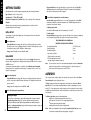
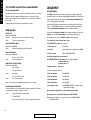
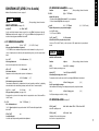
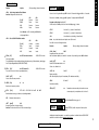
D e u t s c h
I t a l i a n o
E s p a ñ o l
CAL Controls
F r a n ç a i s
CAL 9500P
Programmable
Process Controller
E n g l i s h
Users Manual
E n g l i s h
INDEX
INSTRUMENT PANEL FEATURES
FUNCTIONS MENU
GETTING STARTED
Initial Set-up
AUTOTUNE
Tune or tune at setpoint program
PROPORTIONAL CYCLE-TIME
Cycle-time recommendations
SECOND AND THIRD SETPOINTS (SP2 and SP3)
Error messages
LINEAR INPUT
Set-up procedure
FUNCTION LIST
Level 1
Level 2
Level 3
Output Options Table
Re-transmission
Level 4
Level A
PROGRAMMER
Function overview
Getting started (Programmer)
Program run mode
Display functions
Example program
Function map
Function list
Memory allocation table
Memory full indicator
Programming example
Program edit example
MECHANICAL INSTALLATION
DIN panel cut-out
Mounting
Cleaning
ELECTRICAL INSTALLATION
Typical application
Input options (diagrams)
Output options (diagrams)
INPUT SENSOR SELECTION
Temperature sensors
Linear input
SPECIFICATION
SAFETY AND WARRANTY
2
INSTRUMENT PANEL FEATURES
2
3
4
4
4
5
5
5
5
6
6
6
7
7
7
8
8
8
9
10
11
11
12
12
12
13
14
16
17
17
18
18
19
19
19
19
19
20
21
21
22
22
22
22
23
Green LED:
Setpoint 1 output indicator
Green Display:
Process variable or
Function/Option
Upper Red LED:
Setpoint 2 output
indicator
!
This page can be photocopied and
used as a visual aid and bookmark when
working in other parts of the manual.
Right Red LED:
Program Holdback
indicator
Orange Display:
Setpoint value or
program selection
Lower Red LED:
Setpoint 3 output
indicator
ADJUSTMENTS
To
To
To
To
To
To
To
To
enter or exit program mode:
scroll through functions:
change levels or options:
view setpoint units:
increase setpoint:
decrease setpoint:
reset latched alarm or tune fail:
run or Hold a program:
Notes:
Press ▲ ▼ together for 3 seconds
Press ▲ or ▼
Press ✱ ▲ together or ✱ ▼ together
Press ✱
Press ✱ ▲ together
Press ✱ ▼ together
Press ▲ ▼ together briefly
Press ✱ ▼ together for 3 seconds
If in difficulty by becoming “lost” in program mode, press ▲ and ▼ together for 3
seconds to return to display mode, check the INSTRUMENT ADJUSTMENTS above and
try again.
When in program mode, after 60 seconds of key inactivity the display will revert to
either inPt : nonE or, if the initial configuration has been completed, the measured
value. Any settings already completed will be retained. During Program Configuration it
is recommended that this feature is inhibited. Select ProG StAY in Level 4.
LEVL 4
)
ity 0.5
g
rm
itiv t (
gin (6)
ala n
ns Er.
se x d
Lera 2
-A ; o
av to 3
ve 1.0
i
t
lay r; 1
ble play
va to
i
a
p
r
s
s
i
s
1
d
Di di
Di
De 0.
int
it
po
LL
ex
try
;A
toen
au
V2
E
m
m
L
a
a
k
;
gr
gr Y
loc EV 3
pro StA
pro n
rity ; L
;
le
ge
cu nE
ab to
an f; o
Se no
Ch Of
Dis Au
!
This page can be photocopied and
used as a visual aid and bookmark when
working in other parts of the manual.
DER.S DI.SS NO.AL PROG LOCK SET.L
US E R - P R OTE C TE D S E TTI NGS
;
Ct4
t3;
;C
2
t
ta ; C
on
Da Ct1 S2
or eg
rsi
ve unit
L
nit o d
ne ;
o
AL
Tu Ctb S;
Mo i; l
are lt
T nE;
ad CtA; S1; u
tw onsu
ad Ar; h
f
SE
e
e
o
R
R
C
V
RE no
S
o
r
ly)
.2u
2i
d.2
on
1d
1i.
G
r; 1
d;
ad
e
e
or
2i;
nL
t
s
or
t
ut 1u.2
ts 1r.2
vic ; (re
vic d; A
en ens
ED 1n.
o
en sens
u
e
e
r
tp .2d;
P L 2n;
rn .SC;
tm
stm % s
t d d; rly
/
t d ; SS
u
u
u
u
ito
.
u
j
O 1i
o 1d
jus 25% ale
d 25 cale
tp ; SS
r b ; dn
d
e
tp ; rly
e
on n
a
;
s
u
s
a
o
u
;
r
o
c
r
t ll s
C
to ll s
ns
an
t M f; o
ro
ve .2n
ve 2d
2 o ne
1 o ne
Se uP.S
Se Of
Sp 0.0 fu
Re 1n
Ze 0.0 fu
Re 1r.
SP no
SP no
SP1.D SP2.D BURN REU.D REU.L SPAN ZERO CHEK READ TECH
C O N F I G U R E OUTP UT
S AFE TY S E TTI NGS
CA L IBRAT IO N
UER RSET
PERF O RM A N CE D ATA
;
or
nd P
;
l
r
ns
bA Eo e
ho
% na
se
nso
nly
its
%
%
n
Lt.
%
o; ol;
or
ut tio
um o
um o se
un Ar; Et
od old;
ut ad o
ns
tp por nly
ut
tio ree
ut
e dV.L ; Co
im ax t
p
u
x
u
m
p
p
d
l
t
se
t
t
e
nim t
o
a
lay ; b ; S
o
g
m
;
h
r
r
o
so de
m or le
P2 H;
mi r min le
ou %
ut
m V.hi S.Lo
sp ; °F ; rH
ou 0%
ou 0%
al % p de o
i
e
S
p
e
r
u
s
e
1
l
2
d
1
2
C
0
l
o ca
y
.1
P o
P o
t
an 00 mo
;°C Ph
SP 10
nd Lt nLin
ca Sen ll sca
SP E; d .hi; F
t in E
ca ns
pla r 0
it S 0 t
it S 0 t
lec nE PSi;
ts
n FS
in
co E;
t s Se full s
ad to
lec non
1 m o1
Se no
Se 0.0 fu
Dis 1 o
Se non
Se 0.0
Lim 10
Lim 10
Ma no
Re 0
SP 0 t
Se
INITIAL
LEVL 2
SP1.P HAND
PL.1
PL.2 SP2.A SP2.B DISP HI.SC LO.SC INPT UNIT
\\
MANUAL ADJ US T ME NT S
RA N G IN G
S P 2 MO D ES
➔
CO N F IG U RE IN PU T
SET-UP
ENTRY
r
/
/
% )
c
f
t
ec
in) % F)
P
e)
et)
t)
eo
ch d
1)
ain 00 .6°F
/of se
ga 00 18°
se min
t.S
1s
rat c
oin scal
f
oa
res d
rk
(SP
d/G o 1 /3
on 81
tp
d ( o 1 C/
e ( se
pr An
(re
/of o 8
al An
Pa ; A
ck
se r full
an eg t (2°C
an eg t (10° ime o 60
im 200
or 1 to
ap 0 x b
nu x b ff)
on .1 t
t
o
or ParK
b
l
b
2
a
e
.
e
t
d
e
)
e
P
e
o
d
t
s
e
t
0
s
.
p
l
v
;
p
v to c)
tim ff; 0 sec et (m 50% t = o
ro 0.1 or f/
t S ns cal
yc ff;
ro .1 r f/
ati to 5 )
ral 0.1 in)
ati
oin n
tun on
se
s
jus – se full s
riv
tp f; o
riv f; 1
to ff;
eg ff;
2 C .o
2 p st
o (In.
fs
cle .o 0
1 P t 0 so
Se Of
SP On
De 0.5 (1.5
SP Hy sen
Ad +/
De Of (25
Int O (5 m
Of 0 t
Cy On (2
SP hys sen
Au O
LEVL 1
TUNE BAND INT.T DER.T
➔
KEY ✱ ▼ OR ✱ ▲ TOGETHER TO CHANGE LEVELS OR OPTIONS
LEVL 3
DAC CYC.T OFST SP.LK SET.2 BND.2 CYC.2
)
3A ;
SP .3d
its
PROGRAM ENTRY (DEFAULT)
or E; 2d E
un
int le or
e ooP;
A
e
o
e
e
p
L
3
t
2
S
E
r
a
E.3
L
lu
;
a
ty
im
tp
Ld
e
er
va
(SP 3d ; 2
; d tE
0
be .
e
se l sc
nt EP; L; in mp r 100)
pt
od t; ho
rt
Ld PS
m
ut 2E; .3E
mb
et ful le
alu 15
um ax
(
a
me St dE
am
ure m
sta
nu 31
t r 990 ime
gra n; ho oPY;
t r 60s
t n 26 m
k v 1 to
arg nsor ll sca
eg AK; oP;
utp 2d; ; 2d
ail very ; Con
t
s
n
f
c
n
n
o
m
i
o
i
m
r
.
t
a
e
r
o
a
d
t
C
E
e
;
o
t
o
1
0
t
gr ; SP
jus – se fu
gra 1 to
tp o 9 its/
tp ur;
fin r; S ll;
n p F; o inS;
gm o
we reco rSE
ldb F;
en nE E.3
Se 1 t un
Se 1 t
Se ho
Ru oF
Ad +/
Pro PV
Ev no 2
De SP Ca
Po
Pro
Ho oF
LEVL P
S P 1 S E T T I NGS
PROG
RUN FAIL
SP2 SETTIN G S
ST.U SPRU
SEG TYPE SPRR
T.SP HB.V
EO.P
P R OGR AMME R S E T T I NGS
t
er
un
mb
l
co
nu ber
rva 400
cle 9
ram num s
cy 99
nte to 1
g
i
e
o
o
r
e 1
-pr to gram
1t
m
tim 0. in
ub ; 1
gra nt;
ak nt; ) m
ll s nE pro
So Co (10
Pro Co
Ca no of
s
Level C only visible
when COMMS
Option fitted
LEVL C
es
dr
ad
nt 5
me 25
tru o
ns 0 t
I
0
01
80
18
;4 2
t
y
1;
00 9k
vit
ma 8E
ate 24 ; 1
cti n
for 1; 1
d r 00; 600
a
x a f; o
n
t
u
9
Ba 12
TxR Of
Da 18
SINT PCYC SUB.P
ADDR BAUD DATA DBUC
Range of Adjustment shown
under description.
If applicable, factory settings
shown in bold.
For a full description of menu
functions refer to pages 7 to
10, and 16/17 in Programmer
section.
Note: The letter K appears in
the instrument display as the
character K
C OMMS S E T T I NGS
.0
.0
00 9
0 9999
50 .0
10 .9
10 99
le
le o 9
igh 50
low o 49
sca 9 to
t h to
sca 99 t
t
u
ut
9
w
h
1
9
Lo -19
Inp 0.
Inp 0.0
Hig -1
LEVL A
i;
sh
E
;F
0 r
on .ho
SC
nE nd
3D
uP
3 2 so
no ; bA
e n ; Lt
0 .00
0
e
SP en
P3
0
3od oLd
d VLo oP
00 r 0
0
m
o
O/
0
SP
sis % s le
l
h
E
m
o
d
e
P3 250
ut C
nd Ch;
rse
ere 100 sca
S
im 0.0
in .hi; SLo;
o
t
o
e
s
c
a
t
t
n
S
c L
v 3r
r
F
M dv
Hy 1– full
Se 0 to
De 00
Re
Se
Bu dh
AN.HI ANLO HI.IN LO.IN DECP SP3.A SP3.B SET.3 HYS.3 BRN.3 REV.3
LI NE AR S C ALI NG AND I NP UT S E T T I NGS
SP3 M O D ES
SP3 A D JU STM EN TS
SP3 SA F ETY SETTIN G S
3
KEY ▼ OR ▲ TO VIEW FUNCTIONS
E n g l i s h
FUNCTIONS
MENU
E n g l i s h
GETTING STARTED
After power-up the controller requires programming with the following information:
Press and hold ✱ and use the ▲ or ▼ buttons to select from the choices Rly, SSd or
AnLG depending on the model supplied. SP2 and SP3 outputs will be automatically
allocated. (See output options table on page 8).
Type of Sensor (See list of sensors p.22)
Operating unit °C °F bAr PSi Ph rh SEt
Allocation of Output Device to SP1/SP2 (Relay / SSd) or analogue. SP3 is always relay.
Setpoint
When the above information has been programmed into the controller it will be
operational with factory PID settings.
INITIAL SET-UP
On power-up the controller will display the self test sequence followed by the initial
display inPt : nonE
4 To enter initial configuration into controller memory
Press and hold both ▲ and ▼ buttons for 3 seconds. The display will now read PArK
and measured variable (e.g. ambient temperature 23°). PArK is displayed because a
setpoint has not yet been entered.
To display setpoint units
Press and hold ✱ The displays will now read unit (eg. °C ) and 0
To enter setpoint
Press and hold ✱ and use ▲ button to increase or ▼ button to decrease the reading and
scroll to required setpoint value. (The digit roll-over rate increases with time).
THE CONTROLLER IS NOW OPERATIONAL
WITH THE FOLLOWING FACTORY SETTINGS
1 Select input sensor.
Press and hold ✱ and use the ▲ or ▼ buttons to scroll through the sensor selection
list until the correct sensor is displayed. Release the buttons. The display will now read
selected sensor type e.g. inPt : tCS (type S thermocouple).
Press ▲ once The display will now read unit : nonE
LINEAR INPUT
When Linear Input is selected, the display resolution of the setpoint and many other
functions will be changed from the setting previously made at di.SP in Level 2, to that set
at dECP in Level A.
It is therefore recommended that on completion of the Initial Set-up the Linear Input
settings in Level A be completed before moving on to configure Levels 1, 2 and 3. (see
Set-up Procedure page 6).
2 Select operating unit.
Press and hold ✱ and use the ▲ or ▼ buttons to scroll through the unit selection list
until the correct unit is displayed. Release the buttons. The display will read selected
unit e.g. unit : °C
Press ▲ once The display will now read SP1.d : nonE
3 Select SP1 (Main setpoint output device)
Analogue output
The allocation of the analogue output to SP1 automatically overrides the default
proportional cycle time setting of 20 seconds. Where the analogue output is
allocated to SP2, the default CyC.2 setting on/off must be manually changed in
Level 1 to a time proportioning setting to enable the analogue output to operate in
proportional control mode.
4
Proportional band/Gain
Integral time/Reset
Derivative time/Rate
10ºC/18ºF/100 units
5 mins
25 secs
Proportional cycle-time
(Typical setting for relay output)
DAC Derivative approach control
(Average setting for minimum overshoot)
20 secs
Note:
1.5
For more precise control or for non temperature applications where a Linear input
transducer is being used, the controller may need to be tuned to the process.
Please refer to the following section on AUTOTUNE.
AUTOTUNE
This is a single shot procedure to match the controller to the process. Select either Tune or
Tune at Setpoint from the criteria given below.
The Tune program should be used for applications other than those listed under Tune at
Setpoint below. The procedure will apply disturbances when the temperature or process
reaches 75% of the setpoint value, causing overshoot which is monitored in order to adjust
the DAC overshoot inhibit feature. Care should be taken to ensure that any overshoot is safe
for the process.
The Tune at Setpoint program is recommended when:
● The process is already at setpoint and control is poor
● The setpoint is less than 100°C in a temperature application
● Re-tuning after a large setpoint change
● Tuning multi-zone and/or heat-cool applications.
Notes:
DAC is not re-adjusted by Tune at setpoint. Proportional Cycle Time can be preselected before running the Autotune program. (see page 5).
SECOND AND THIRD SETPOINTS (SP2 and SP3)
Hereafter in the Manual the symbol (▲▼) signifies both buttons are held pressed
for 3 seconds to ENTER or EXIT Program mode.
TUNE OR TUNE AT SETPOINT PROGRAM
PRIMARY ALARM MODES
Configure SP2 output to operate as an alarm from SP2.A in Level 2 and set the alarm
setting in SEt.2 Level 1.
Enter program (▲▼) and from the display tunE : oFF press and hold ✱ and press ▲ to
display tunE : on or tunE : At.SP Exit program mode (▲▼).
Configure SP3 alarm mode SP3.A and setting SEt.3 in Level A. The alarms will be
individually triggered when the process value changes according to the options listed
below.
The TUNE program will now start. The display will show tunE as the process variable
climbs to setpoint.
dV.hi
Rises above the main setpoint by the value inserted at SEt.2/3.
dV.Lo
Falls below the main setpoint by the value inserted at SEt.2/3.
BAnd
Rises above or falls below the main setpoint by the value inserted at SEt.2/3.
FS.hi
Rises above the full scale setting of SEt.2 or SEt.3.
FS.Lo
Falls below the full scale setting of SEt.2 or SEt.3.
EoP
Event Output (See Programmer section pages 11 to 18)
Note: Avoid tuning while running a program as SP1 may be different from the target
setpoint..
When the TUNE or TUNE AT SETPOINT program is complete the PID values are entered
automatically. The process will rise to setpoint and control should be stable. If not, this may
be because optimum cycle time is not automatically implemented. To set the cycle time
see PROPORTIONAL CYCLE-TIME.
SUBSIDIARY SP2 / SP3 MODES
The following additional Subsidiary alarm functions can be added to any Primary alarm
configurations using the settings found at SP2.b in Level 2 and SP3.b in Level A.
PROPORTIONAL CYCLE-TIME
The choice of cycle-time is influenced by the external switching device or load. eg.
contactor, SSR, valve. A setting that is too long for the process will cause oscillation and a
setting that is too short will cause unnecessary wear to an electro-mechanical switching
device.
Factory set
To use the 20 sec factory set cycle-time no action is needed whether autotune is used or
not.
To Manually Select AUTOTUNE Calculated CYCLE-TIME
When AUTOTUNE is completed, enter program (▲▼) and select CYC.t in Level 1. The
display will read CYC.t : 20 (the factory setting).
To view the new calculated optimum value, press and hold both ✱ and ▼ buttons until
indexing stops. The calculated value will be displayed eg. A16. If acceptable, exit program
(▲▼) to implement this setting.
To Pre-select Automatic Acceptance of AUTOTUNE Calculated CYCLE-TIME
Before AUTOTUNE is initiated select CYC.t in Level1, press and hold both ✱ and ▼ buttons
until indexing stops at A – – . Exit program (▲▼) to accept calculated value automatically.
LtCh
Once activated, the alarms will latch and can be manually reset when the alarm
condition has been removed.
Hold
This feature inhibits alarm operations on power-up and is automatically disabled
once the process reaches the alarm setting.
Lt.ho
Combines the effects of both LtCh and hoLd and can be applied to any Primary
alarm configuration.
SECOND SETPOINT (SP2) Proportional control output
Configure in Level 1 using CyC.2 to select proportional cycle time and bnd.2 to adjust
proportioning band. For Heat/Cool operation see Operating Manual.
Additional in depth information on controller operation is available in the CAL 9400.PDF
available for down load from www.cal-controls.com
In on–off mode, bnd.2 adjusts SP2 hysterisis.
Alarm type On-Off operating mode SP2 and SP3 Proportional operating mode SP2 only
Deviation
Output state
LED state
Output state
DV.HI
BAND
BAND : on-off mode only
Factory Setting
20 seconds
20 seconds
Output OFF
(Relay or SSd
de-energised)
FS.LO
Recommended Minimum
10 seconds
0.1 seconds
Output ON
(Relay or SSd
energised)
Full scale
FS.HI
CYCLE-TIME RECOMMENDATIONS
Legend
LED state
DV.LO
To Manually Pre-select Preferred CYCLE-TIME
Before AUTOTUNE is initiated select CYC.t in Level 1, press and hold both ✱ and ▲ or ▼
buttons until indexing stops at preferred value then exit program (▲▼) to accept.
Output Device
Internal relays
Solid state drives
E n g l i s h
AUTOTUNE (continued)
COOL
Temperature above setpoint
Strategy
LED ON
5
E n g l i s h
SP2 / SP3 OUTPUT AND LED STATUS IN ALARM CONDITION
LINEAR INPUT
SP2 / SP3 ALARM ANNUNCIATOR
Set-up Procedure
If a Primary Alarm mode has been configured, when an alarm condition occurs the alarm
annunciator -AL- will be displayed alternating with the process variable. The alarm
together with the display, will be automatically reset as soon as the alarm condition has
been cleared.
The 4–20mA input model converts current into voltage using an internal resistor which
spreads the signal across the input range 10 to 50 mV. using multiplier of 2.5. When using a
transducer with an output less than 4–20mA, the input maximum and minimum mV values
can be calculated using the same multiplier.
The annunciator may be disabled by selecting no.AL: on, in Level 4.
Models with 0 to 5V input use an internal resistor to spread the signal across the input
range
0 to 50 mV using a divider of 100. Where a transducer provides a smaller
output, the input maximum and minimum values can be similarly calculated.
ERROR MESSAGES
Decide what scale minimum and maximum will be required, and whether the scale needs
inverting. (See Level A; Linear Input Scaling for list of settings and limits, page 10).
SENSOR FAULT
Display flashes: inPt: FAiL
Indicates:
sensor open or short circuit or linear input over-range.
Action:
Check sensor/wiring/connectors
The example below shows how a 4–20mA linear Input should be configured.
# e.g. 4–20mA = 60 to 260 units where 4mA = 60 units
NON-VOLATILE MEMORY ERROR
Display flashes: dAtA : FAiL
Action:
De-power briefly. Replace unit if problem persists
Follow INITIAL SET-UP procedure (also see page 4).
MANUAL POWER ERROR
Display flashes: hAnd : FAiL
SP1 set to on–off in CYC.t
Action:
Select proportional mode
1. Select input sensor
Select inPt:Lin
2. Select unit
Select required unit, if not available Select unit:SEt
3. Select SP1 output
Select from: Rly, SSd or AnLG
Enter initial configuration into controller memory
DO NOT ENTER SETPOINT until Linear Input has been configured in Level A
See functions menu page 3
and functions list page 10.
IMMEDIATE FAIL ON AUTOTUNE START
Display flashes: tunE : FAiL
Setpoint display 0
1. No setpoint entered.
Configure Linear Input
Enter level A
(Then using example given # above)
Action:
Enter setpoint
4. Enter scale maximum
Select An.hi:260
5. Enter scale minimum
Select An.Lo:60
Action:
2. SP1 set to ON/OFF in CyC.t
Select proportional mode
6. Enter input maximum
Select hi.in:50.0
Note: To reset and clear error press ▲▼ together briefly to cancel message.
7. Enter input minimum
Select Lo.in:10.0
FAIL LATER DURING AUTOTUNE CYCLE
The thermal characteristics of the load exceed the Autotune algorithm limits. The failure
point indicated by any display 0.0 in tech e.g. Ctb = 0.0
8. Enter display resolution
Select dECP:0000 (WARNING – otherwise settings
marked ✢ may be altered)
Action:
Enter Linear Input configuration into controller memory and enter setpoint.
1.
Change the conditions. eg. raise setpoint
Now configure Levels 1, 2 and 3 and if required proceed with AUTOTUNE.
2.
Try tunE : At.SP
3.
If the error message persists, call local CAL representative for advice.
Note: Any apparent calibration errors can be removed using the ZEro and SPAn
adjustments in Level 3.
6
✢
Will be affected by dECP settings in Level A
Note: A Functions Menu is shown on page 3.
LEVEL 1
Function
SELECT AUTOTUNE
Options
SEt.2
[0] to * °C/°F/units
Adjust SP2 setpoint
* Deviation Alarms DV.hi, DV.Lo, bAnd 25% sensor maximum.
* Full scale alarms FS.hi, FS.Lo sensor range f/s
✢
bnd.2
0.1 - * °C/°F/units
Adjust SP2 hysteresis or proportional band/gain
(see CyC.2 setting)
* 100% sensor f/s (Hi.Sc)
[Factory settings] shown in brackets
(see pages 4/5)
tunE [oFF]
on PArK At.SP
Used to switch the Autotune feature on and off, to select PArK or Autotune at setpoint.
PArK temporarily turns the output(s) off. To use select PArK and exit program mode. To
disable re-enter program at tunE and select oFF.
✢ SP1 OPERATING PARAMETERS
bAnd
0.1 to * C/°F
[10ºC/18ºF/100 units]
SP1 proportional band/Gain or Hysteresis
* 100% (Hi.Sc) sensor maximum Proportional control eliminates the cycling of on-off
control. Output power is reduced, by time proportioning action, across the proportional
band.
(see page 6)
[Factory settings] shown in brackets
✢
LEVL 1
Function
Options
E n g l i s h
SP2 OPERATING PARAMETERS
FUNCTION LIST (LEVELS 1 to 4 and A)
[2.0 °C/3.6°F 2 units]
CyC.2 [on.oFF]
0.1–81 seconds
Select SP2 ON/OFF or proportional cycle-time
Select on.oFF for ON/OFF mode, or the cycle rate of SP2 output device for proportional
mode.
LEVEL 2
LEVL 2
MANUAL CONTROL MODES
int.t oFF
0.1 to 60 minutes
SP1 integral time/reset
Auto-corrects proportional control offset error
[5.0]
Function
[Factory settings] shown in brackets
SPI.P
0 to 100 % ‘read only’
Read SP1 output percentage power
dEr.t oFF
1 - 200 seconds
[25]
SP1 derivate time/rate
Suppresses overshoot and speeds response to disturbances
dAC
0.5 - 5.0 x bAnd
[1.5]
SP1 derivative approach control dAC
Tunes warm-up characteristics, independent of normal operating conditions, by adjusting
when derivative action starts during start-up (smaller dAC value = nearer setpoint).
CyC.t A – – on.oF
0.1 - 81 sec
[20]
SP1 proportional cycle-time (see pages 9/10)
Determines the cycle rate of the output device for proportional control. Select on.oF for
ON/OFF mode.
✢
Options
hAnd [oFF]
1 to 100 % (not in ON/OFF)
SP1 manual percentage power control
For manual control should a sensor fail. Record typical SP1.P values beforehand.
PL.1
100 to 0 % duty cycle
[100]
Set SP1 power limit percentage
Limits maximum SP1 heating power during start-up and in proportional band.
PL.2
100 to 0 % duty cycle
Set SP2 percentage power limit (cooling)
[100]
SP2 OPERATING MODES (see page 5)
oFSt
0 to * °C/°F/units [0]
SP1 offset/manual reset
* ±50% bAnd. Applicable in proportional and ON/OFF mode with integral disable:
Int.t : oFF.
SP2.A [nonE]
Main SP2 operating mode
SP.LK [oFF]
on
Lock main setpoint
Locks the setpoint preventing unauthorised adjustment.
SP2.b [nonE]
LtCh hoLd nLin
Subsidiary SP2 mode: latch/sequence
Non-linear cool proportional band
dV.hi dV.Lo bAnd FS.hi FS.Lo Cool EoP
7
✢
Will be affected by dECP settings in Level A
E n g l i s h
LEVEL 2 CONTINUED
INPUT SELECTION AND RANGING
Re-transmission
dI.SP [1]
0.1
Select display resolution: for display of process value, setpoint, OFSt, Set.2, hi.SC, LoSC.
* These models above offer the option of using the analogue output for Re-transmission.
Select bAnd or bnd.2 value in LEVL 1 to equal the full range setting in LEVL A and if
using SP1 output, set int.t and dErt.t in LEVL 1 to off.
✢
hi.SC [sensor maximum]
Set full scale
✢
Lo.SC [sensor minimum]
sensor minimum °C/ºF/units
Set scale minimum (default 0°C/32°F or 0 units)
sensor maximum °C/°F/units
Example: Set-Up using a Model 95B11P to Re-transmit the 4-20 mA input, scaled 0 to 100
units. SP1 relay is used as the control output and SP2 analogue output is used for retransmission.
Note: Read in conjunction with Linear Input Set-up Procedure on page 6.
inPt Select input sensor [nonE]
(See SENSOR SELECTION table, page 22)
NB. If Linear Input selected, start configuration from Level A.
Function
From initial power-up;
Set
inPt nonE
unit nonE
SP1.d nonE
unit [nonE]
°C °F bAr Psi Ph rh SEt
Select required operating unit from above options
LEVEL 3
Options
to
to
to
To scale the input, select LEVL A, then:
Set
dECP
to
An.hi
to
An.Lo
to
hi.in
to
Lo.in
to
LEVL 3
OUTPUT CONFIGURATION
Note 1: ‘Read only’ after initial configuration. rSET ALL full reset to factory settings
required to change SP1.d subsequently.
[Factory settings] shown in brackets
inPt Lin
unit SEt (for example)
SP1.d rLY
000.0 (e.g. required resolution)
100.0
0.0
50 (ie 20mA)
10 (ie 4mA)
To align SP2 analogue re-transmission with SP1 control output, select LEVL 2 then:
Set
SP2.A
to
FS.hi
Note 2: Depending on the Model, SP1 and SP2 may be fitted with any of three output
types, RLY, SSd or Analogue (Specification on page 11/12) where appropriate,
these must be allocated during initial configuration. SP3 is always fitted with RLY.
And in LEVL.1
Set
Output Options Table
Finally, set SP1 setpoint value as required for process to start.
Model
SP1 Output
SP2 Output
SP3 Output
95111P
RLY
RLY
RLY
95001P
SSd
RLY
RLY
SSd
RLY
RLY
95221P
SSd
SSd
RLY
*95X11P
AnLG
RLY
RLY
AnLG
RLY
RLY
AnLG
SSd
SSd
AnLG
RLY
RLY
*95X21P
SEt.2
bnd.2
Using SP1 output for re-transmission
Set
int.t
to
dErt
to
rev.d
to
SP1 Setpoint to
50 (ie 50% of display range)
100 (ie 100% of display range)
off
off
1d.2d to invert SP1 output
midscale
burn Sensor burn-out/break protection
Caution: Settings affect fail safe state.
[uP.SC]
dn.SC
1u.2d
1d.2u
* Substitute for X in table above, Analogue options B = 4–20mA, C = 0–5V, D = 0–10V
SP1
Upscale
Downscale
Upscale
Downscale
SP2
Upscale
Downscale
Downscale
Upscale
Retransmission range is limited to the sensor full scale value (Example RTD = 400C/752F).
8
✢
to
to
Will be affected by dECP settings in Level A
E n g l i s h
LEVEL 3 CONTINUED
Function
Options
[Factory settings] shown in brackets
rEu.d Select output modes: Direct/Reverse
Caution: Settings affect fail safe state.
[1r.2d]
1d.2d
1r.2r
1d.2r
SP1
Reverse
Direct
Reverse
Direct
SP2
Direct
Direct
Reverse
Reverse
Enter level 4 at Lock, release ▲ and ▼ together. Display reads LoCK nonE
Program security using Lock [nonE]
Select from three Lock options: Press and hold ✱, press ▲ to index.
Select SP1/2 LED indicator modes
[1n.2n]
1i.2n
1n.2i
1i.2i
✢
✢
SP1
Normal
Invert
Normal
Invert
SP2
Normal
Normal
Invert
Invert
rEAD [Var]
hi
Read control accuracy monitor
locks level 3, 4, A (and C when fitted)
LEV.2
locks level 2, 3, 4, A (and C when fitted)
ALL
locks all functions (including C when fitted)
Any locked functions and options can still be read.
Press ▼ to access following functions.
Function
SPAn [0.0]
to ±25% sensor maximum
-1999–2500 in Linear
Sensor span adjust
For recalibrating to align readings with another instrument e.g. External Meter, data logger.
See Full Operating Manual (ADVANCED SETTINGS).
ZEro
[0.0]
to ±25% sensor f/s
Zero sensor error (see Sensor span adjust above).
LEV.3
Note:
Options
ProG [Auto]
StAY
Program mode auto-exit switch
Auto-exit returns display to normal if 60 seconds of key inactivity, select StAY to disable
no.AL [oFF]
on
Disable SP2 alarm annunciator -ALSelect on to disable -ALdi.SS dir
1 to 32
[6]
Display sensitivity
dir = direct display of input 1 = maximum, 32 = minimum sensitivity
Lo
dEr.S
Derivative sensitivity
0.1 to 1.0
SEt.L (oFF)
on
✢ tECh
[Ct A]
CT b Ct 1 Ct 2 Ct 3 Ct 4 oS 1 uS oS 2
Read Autotune tuning cycle data (see Operating Manual)
UEr
[Factory settings] shown in brackets
-1999–2500 in Linear
ChEK [oFF]
on
Select control accuracy monitor
✢
LEVL 4
Access to level 4 is gained through UEr in level 3. Press and hold ▲ and ▼ for 10 seconds.
Select Reverse on SP1 for heating and Direct for
cooling applications.
rEu.L
LEVEL 4
Software version number
rSET [nonE]
ALL
Resets all functions to factory settings
Caution: This selection will lose all of the current settings.
[0.5]
Remember next menu exit point and use as new
menu entry point, except when exit is in Level 1.
LEVEL P
LEVL P
See PROGRAMMER Section, page 11.
LEVEL C
LEVL C
COMMS SETTINGS; visible only when Comms option
fitted.
Additional in depth information on controller operation is available in the APPGUIDE.PDF
available for down load from www.cal-controls.com
9
✢
Will be affected by dECP settings in Level A
E n g l i s h
LEVEL A
Function
LEVL A
Function
Options
[Factory settings] shown in brackets
Linear Input Scaling
Options
brn.3 [uPSC]
uPSC or dnSC
Sensor burn-out / break protection
Select upscale or downscale
Please read in conjunction with Linear Input Set-up Procedure on page 6.
✢
An.hi
-1999 to 9999
Adjusts required scale maximum
[1000]
✢
An.Lo
-1999 to 9999
Adjusts required scale minimum
[0]
hi.in
Configure input maximum
[50.0]
0.1 to 50.0
rEV.3 [3d]
3d or 3r
Reverse SP3 output mode
Select direct or reverse operation
Lo.in
0.0 to 49.9
[10.0]
Configure Input minimum
This setting must be at least 0.1 less than the setting for hi.in above.
Note: Refer to Linear Input conversion factors detailed in the Set-up Procedure on page 6.
dECP
000.0 to 00.00
[0000]
Scale resolution
NB. Once the Linear Input option has been selected, the setting here over-rides the scale
resolution setting di.SP in Level 2 and will affect the following display readings:
Level A:
An.hi; An.Lo; Set.3; hYS.3
Level 1:
bAnd; ofSt; SPrr; SEt2; bnd.2
Level 2:
hiSC; LoSC
Level 3:
SPAn; ZEro; rEAd; tECh
SP3 SETTINGS
SP3.A [nonE]
Main SP3 operating mode
dV.hi dV.lo bAnd FS.hi FS.Lo EoP
SP3.b [nonE]
LtCh hoLd Lt.ho
Subsidiary SP3 operating mode
SEt.3
SP3 setpoint adjustment
0 to 2500
[0]
hyS.3
Set SP3 hysteresis
0.1 to 100% of hiSC
[20]
10
✢
Will be affected by dECP settings in Level A
[Factory settings] shown in brackets
INDEX
Function overview
11
Getting started
12
Program run mode
12
Display functions
12
Example program
13
Function map
14
Function list
16
Memory allocation table
17
Memory full indicator
17
Programming example
18
Program edit example
18
E n g l i s h
In addition to those settings that determine the segment profile, it is also necessary to set
program start values, together with the preferred ramp rate time units for each individual
program.
PROGRAMMER
At the end of a sequence, a Program can be arranged to repeat (Loop), either a specified
number of Cycles, or continuously. Only one Loop can be included in a Program. When
the program is running, the Display indicates progress through the sequence of segments,
and can additionally be interrogated for further segment information.
It is also possible to CALL an already existing program as a sub program that can be
inserted as a segment of another program.
To speed up Program configuration, several Edit functions have been provided so that
individual Segments and Programs may be Deleted or Inserted, and an entire Program
may be Copied and then Pasted into another that it will replace.
For safety reasons, three modes of recovery from a power failure are available. These either
automatically Re-start the Program from the beginning, Continue it from where it stopped,
or Hold it waiting for a user re-start.
FUNCTION OVERVIEW
The Programmer function in Level P enables the Model 9500P to control applications
needing Setpoint changes over time. Examples of this are Ramp changes where a gradual
Rate of change can be set, or Step changes which are instantaneous. These can be
separated by Soak periods during which the process is held at a constant value. Each
individual time interval of the program or Segment, together with it’s associated moving
setpoint value can be stored as a unique Program and for example be represented by the
diagram below.
Setpoint
Soak
Step
Either one or both of the two auxiliary outputs can be configured as Event outputs.
Engaging the Holdback feature will temporarily halt Setpoint ramping to allow the process
temperature to catch up should it deviate by more than a pre-set amount during a Ramp
segment.
To afford maximum programming flexibility, memory is allocated dynamically, and not preallocated. This allows the user the freedom to configure a small number of long programs
or a larger number of shorter ones, up to the permitted maximum of 126 Segments per
program, and a limit of 31 Programs. Should these limits be exceeded, or the Programmer
memory become fully used, the display will read ProG FULL. Programs can be planned
using the Memory Allocation Table which details the memory requirements of individual
segment types. During configuration a check can be kept on memory usage by
interrogating the USEd feature of the display to give an instant reading of ‘percentage
memory used’.
Finally, once a program has been configured, it can be run from the run off/on/hold
controls in Level P, and in addition a quick access run/hold toggle is directly available from
the front panel.
The Programmer Functions List describes the full range of available Settings for each
Programmer Function together with their display mnemonic. The Model 9500P is supplied
with a suite of Factory Settings for each Function. These are shown in bold type.
The Functions Map illustrates the relationship between the Functions and their Settings
and provides a guide to the Keying Operations required to navigate around the menu
when configuring or running a Program.
Ramp
Time (Segments)
11
GETTING STARTED (PROGRAMMER)
For users with previous experience of configuring programmers, the
12
E n g l i s h
EXAMPLE PROGRAM
TYPE
TYPE
TYPE
TYPE
TYPE
TYPE
TYPE
TYPE
TYPE
SPR
SOAK
STEP
SPR
LOOP
SPR
SOAK
STEP
SPR
SPRR
SINT
T.SP
SPRR
PCYC
SPRR
SINT
T.SP
SPRR
105
45
85
55
1
105
45
85
55
Temp
T.SP
T.SP
T.SP
T.SP
30
137
30
Soak Function
137
Interval: 45 mins
Ramp Function
Rate, 105 deg/hour
Target setpoint: 137 deg
Step Function
Target setpoint: 85 deg
Ramp Function
Rate, 55 deg/hour
Target setpoint: 30 deg
STOP
30
Loop Function
Number of repeat
program cycles: 1
SEG
SEG
SEG
SEG
SEG
SEG
SEG
SEG
SEG
1
2
3
4
5
1
2
3
4
Time
PROG See segment configuration of this
3 program detailed on page 18.
13
E n g l i s h
PROGRAMMER FUNCTION MAP
START HERE
Press and hold
▼▲
for 3 seconds
ENTER
PROGRAM
Paste only appears
after a program is
copied
TUNE
OFF
Copies the
selected
program
To add new
program,
press ▲ once
▼
PROG
ADD
▲
RUN
OFF
EDIT
PSTE
EDIT
COPY
Program
editing
functions.
Insert
EDIT
INS
Program
editing
functions.
Delete
EDIT
DEL
✱
3 secs
✱
3 secs
✱
3 secs
SURE
YES
SURE
✱ ▲
NO
PROG
3
✱
3 secs
PROG
1
A copy of program 1 can be
pasted into another program
PROG
2
Another program has been
inserted into PROG 2
re-numbering existing
PROG 2 to 3
Program 1 has
been copied to
program 3
Program 3 has been
deleted. Display
shows next program
down from top of list
▼
LEVL
1
PROG
3
✱ ▼
Add new
programs at
top of existing
menu
Program 3
now appears
in list
Hold the
program at
current position
RUN
HOLD
Start program when ‘on’
selected. This locks
other options out
RUN
ON
✱
3 secs
PROG
2
If COMMS option
fitted, LEVEL C
appears between
LEVEL P and LEVEL A
LEVL
C
To view existing
programs 1 to 31
or full?
LEVL
P
✱
▼
LEVL
A
14
▲
✱
▲
PROG
1
✱
▼
USED
0
Program
‘off’ state
▲
Select the required
program number.
Default: 1
Memory used (%)
✱
▲
SURE
YES
SURE
✱ ▲
NO
Hold the
program at
the point it
stopped
Continue the
program
from where
it stopped
Reset the
program at
beginning
PROG
2
✱
3 secs
FAIL
HOLD
ST.V
SP
FAIL
CONT
✱
▲
Options: start
program at main
SP or process
variable
RUN
▲
OFF
FAIL
▲
RSET
Select program mode
of operation
Default: off
Power failure recovery
position
Default: reset
✱
SPRU
60 S
Options:
hours
minutes
▲
ST.V
PV
▲
Select the starting point of
program after power up
Default: PV
✱
▲
SPRU
HOUR
▲
Ramp rate time units
adjustment
Default: hour
▲
EDIT
INS
Delete a
segment
EDIT
DEL
Event
output
To add new
segments
press ▲ once
SEG
ADD
Insert new
segment in
the menu
✱
3 secs
✱
3 secs
New segment now
inserted into 2. Old
segment 2 becomes 3
SEG
2
SURE
✱ ▲
NO
SURE
YES
Call up
another
program
Add new
segments at
top of existing
list
Segment 3
now appears
in menu
Program
re-cycles
Step
Soak
✱
▲
SEG
1
Ramp
▲
Set the segment to be
adjusted
Default: 1
Segment 3
deleted
3 secs
E.OP
2E3D
E.OP
2D3D
TYPE
CALL
Returns to
SEG
SUB.P
NONE
E.OP
3E
Set Numbers of
re-cycles 1 to 999 unless
full. Or continuous
Default: 1
TYPE
LOOP
PCYC
1
TYPE
STEP
Soak time in minutes
or continue
Default: 10
SEG
2
To view existing
segments 1 to 126
or full?
SEG
2
✱
TYPE
E,OP
▼
SEG
3
E.OP
2D3E
E.OP
2E3E
Define the program
number called
Default: none
TYPE
SPR
E n g l i s h
Event output options
energise and de-energise
for all combinations of
SP2 & SP3.
TYPE
SOAK
✱
▲
Important note
Up ▲ button must be
used after selecting the
segment type to
confirm it’s selection
TYPE
▲
SPR
To select operational
mode of each segment
Default: Ramp
E.OP
3D
‘Hold back band
size adjustable
0.1 to 150 units
T.SP
9999
HB.V
150
SINT
10
E.OP
2D
✱
SPRR
▲
100
Adjusts ramp
rate
Default: 100
E.OP
2E
▲
T.SP
▲
0.0
Target set point adjustable
over the unit’s range
Default: Current main SP
✱
▲
HB.V
▲
OFF
‘Hold back’ this function only
appears for ramp operational
once a value is set
Default: off
✱
▲
E.OP
▲
NONE
Event output – options only
appear when SP2A or SP3A
modes set to E.OP
Default: de-energise
15
E n g l i s h
Function
FUNCTION LIST (LEVEL P) PROGRAMMER
LEVEL P
Press ▲ or ▼ to change
TyPE
Press ▲ or ▼ to change
Press ✱ ▲ or ✱ ▼ to change
ProG
Program number
[1]
Add new programs (1 to 31)
run
Run Program
[oFF]
Program not running
on
Run program
hoLd
Pause program
Edit dEL
Delete program
†❖
Edit inS
Insert new program
†
Edit CoPy
Copy another program †
Edit PStE
Paste copied program †
[rSEt]
Reset to program start
Cont
Continue from interruption
hoLd
Hold at interruption (User re-start)
[PV]
Process value
SP
Setpoint value
[hour]
Ramp rate adjust in hours
60 s
Ramp rate adjust in minutes
[1]
Add new segments (1 to 126) ❋
SPru
SEG
Press ✱ ▲ or ✱ ▼ to change
Define segment type
SPr
SPrr
Settings [Factory settings] shown in brackets
Function
St.V
Power failure recovery mode
Program start value
Ramp rate time units
Segment number
Ramp to next target setpoint
[100] Setpoint ramp rate Units per
hour/minute (0-9990) (as set at
Spru above)
t.SP
(Segment target setpoint)
adjustable over instrument’s
configured range
hb.u
Hold back [oFF] sets the
permitted band size for the
measured value to deviate from
the ramp setpoint before the
program is ‘held back’ waiting for
the measured value to catch up.
(0.1 to 150 units)
SoAK
Sint
StEP
Hold setpoint for pre-set time [10]
Soak time, adjust in minutes
(cont.-1440) x 0.1
Step to new target setpoint (Set
tSP as above)
LooP
PCYC
CALL
Sub.P
16
Settings [Factory settings] shown
in brackets
LEVL P
Access Level P from Level 1. Press and hold ✱ ▼
Fail
Sub-functions
Re-cycle program
[1] Set number of program loops
up to 999, or continuous loop ❋
Call up another program by
number to import into this
program
(nonE) Number of Program called
at Call above
Edit dEL
Delete segment † ❖
Edit inS
Insert new segment †
†
See examples of EDIT procedures (page 18)
❖
Deleting a Program automatically re-numbers those programs with higher numbers
❋
Until memory full. See page 11 for further explanation and memory allocation table
on page 17.
E.oP
Press ▲ or ▼ to change
Press ✱ ▲ or ✱ ▼ to change
Event output
[nonE]
Segment type
Memory required
Ramp
4 Bytes
Loops (4+)
2 Bytes
2d
SP2A de-energised to mark event
Call
1 Byte
2E
SP2A energised to mark event
Event Output
1 Byte
3d
SP3A de-energised to mark event
Program Header
1 Byte
3E
SP3A energised to mark event
2d.3d
SP2A and SP3A de-energised to
mark event
SP2A energised SP3A de-energised
to mark event
2E.3E
SP2A and SP3A energised to mark
event
2d.3E
SP2A de-energised SP3A energised
to mark event
To Return to:
LEVL P
Memory Allocation Table
Function can be applied to each
segment independently to trigger
an output at the start of that
segment for the duration of that
segment. Setting blocked unless
either or both outputs SP2A or
SP3A have been configured as an
Event Output in Level 2 or Level A
respectively.
2E.3d
E n g l i s h
Settings [Factory settings] shown in brackets
Function
Ramp with Holdback
5 Bytes
Soak
2 Bytes
Step
3 Bytes
Loops (1–3)
1 Byte
Maximum capacity:
351 Bytes
31 Programs
126 Segments
Examples:
1. 1 program of 58 Ramps and 58 Soaks
349 Bytes
2. 4 programs of 14 Ramps and 14 Soaks
340 Bytes
3. 31 programs of 2 Ramps and 1 Soak
341 Bytes
4. 2 programs of 10 Ramps, 10 Soaks, 2 Steps and 1 loop
136 Bytes
Press and hold ▼
Memory Full Indication
To Read % Programmer memory used:
USEd
Press ✱ and ▼ together in LEVL P / ProG 1
Should the programmer memory capacity be reached during program configuration, the
display will show ‘FULL’
1–100%
17
E n g l i s h
PROGRAMMING EXAMPLES
SURE
YES
✱
3 secs
PROG
2
Program 1
now pasted
as Program 2
KE Y
Arrows drawn thus
signify several key
operations
Program Edit Function
KEY ✱ ▼ OR ✱ ▲ TOGETHER TO VIEW OR CHANGE SETTINGS
Make copy of Program 1 and paste as
new Program 2
18
ADD
(next)
PROG
EDIT
PSTE
✱
3 secs
SURE
NO
Programmer functions
shown as white
characters on black
background have
Default settings
RUN
OFF
KEY ▼ OR ▲ TO VIEW FUNCTIONS
EDIT
COPY
PROG
1
PROG
3
✱
3 secs
PROG
1
RUN
OFF
Program settings for functions:
run; FAiL; St.U and SPru
not shown, are all set to Default
SEG
ADD
Program Segment Configuration
See Program 3 illustrated on page 13
SEG
5
TYPE
LOOP
PCYC
1
SEG
4
TYPE
SPR
SPRR
55
SEG
3
TYPE
STEP
SEG
2
TYPE
SOAK
SINT
45
SEG
1
TYPE
SPR
SPRR
10 S
T.SP
30
T.SP
85
T.SP
137
HB.V
OFF
E.OP
NONE
E n g l i s h
MECHANICAL INSTALLATION
ELECTRICAL INSTALLATION
(See important Safety Information page 20)
The Controller is designed to be sleeve mounted in a 1/16 DIN panel cutout with only the
front panel rated to NEMA4/IP66, provided that:
● the panel is smooth and the panel cutout is accurate;
OUTPUT DEVICES
WARNING:
Three types of output device may be factory fitted to the controllers, and users must choose
how to allocate these to outputs SP1 and SP2. (SP3 is always RLY). Check the model number
and output configuration against the Output Options Table on page 8 before wiring the
instrument and applying power.
● the mounting instructions are carefully followed.
DIN PANEL CUTOUT
1/16 DIN: 45.0mm +0.6 / -0.0 wide, 45.0mm +0.6 / -0.0 high
Minimum spacing 20mm vertical, 10mm horizontal
1 Solid state relay drive (SSd1/SSd2)
6Vdc (nominal) 20mA max.
To switch remote SSR (or logic)
MOUNTING
2 Miniature power relay (rLY/rLY1/rLY3)
2A/250V AC resistive, Form A/SPST contacts.
Maximum panel thickness 9.5mm
To mount a Controller proceed as follows:
1 Check that the controller is correctly orientated and then slide the unit into the cutout.
2 Slide the panel clamp over the controller sleeve pressing it firmly against the panel until
the controller is held firmly.
3 The controller front bezel and circuit board assembly can be unplugged from the sleeve.
Grasp the bezel firmly by the recesses on each side and pull. A screwdriver can be used
as a lever if required.
3 Analogue Output (AnLG) (isolated)
Specify; 4–20mA 500Ω max +/- 0.1% fs typical
0–5Vdc 10mA (500Ω min) +/- 0.1% fs typical
0–10Vdc 10mA (1KΩ min) +/- 0.1% fs typical
SUPPLY VOLTAGE
100–240V 50–60HZ 6.0VA (nominal)
+/- 10% maximum permitted fluctuation
4 When refitting the bezel assembly it is important to press it firmly into the sleeve until the
latch clicks in order to compress the gasket and seal to NEMA4X/IP66.
WIRING THE CONNECTOR
Prepare the cable carefully, remove a maximum of 8mm insulation and ideally tin to avoid
bridging. Prevent excessive cable strain. Maximum recommended wire size: 32/0.2mm 1.0mm2
(18AWG).
CLEANING
Wipe down with damp cloth (water only)
CAUTION: The controller should be isolated before removing or refitting it
in it’s sleeve. Live circuits can hold a charge for short periods after isolation
from voltage supply. Electrostatic precautions should be observed when
handling the controller outside it’s sleeve.
INDUCTIVE LOADS
To prolong relay contact life and suppress interference it is recommended engineering practice
to fit a snubber (0.1uf/100 ohms) between relay output terminals.
DIMENSIONS
Bezel*
Width
Height
51.0
51.0
Behind Panel
Width
Height
44.8
44.8
Overall
Length
Behind panel
Length*
116.2
106.7
CAUTION:
Snubber leakage current can cause some electro-mechanical devices to be held ON.
Check with the manufacturers specifications.
Dimensions in mm
* includes gasket
19
E n g l i s h
EN61010 - /CSA 22.2 No 1010.1 92
TYPICAL APPLICATION
Compliance shall not be impaired when fitted to the final installation.
Designed to offer a minimum of Basic Insulation only.
The body responsible for the installation is to ensure that supplementary insulation suitable for
Installation Category II or III is achieved when fully installed.
Heater
Analogue
power
controller
To avoid possible hazards, accessible conductive parts of the final installation should be
protectively earthed in accordance with EN61010 for Class 1 Equipment.
Output wiring should be within a Protectively Earthed cabinet.
(+)
* Sensor sheaths should be bonded to protective earth or not be accessible.
A clear instruction shall be provided not to position the equipment so that it is difficult to
operate the disconnecting device.
Model
EMC Immunity
EMC immunity may be improved by fitting large Ferrite cores around the sensor cables at the
point where they enter the cabinet and an earth bond is recommended.
F1 Fuse:
1A time lag type to IEC127. CSA/UL rating 250Vac
F2 Fuse:
High Rupture Capacity (HRC) Suitable for maximum rated load current
S1 Switch:
IEC/CSA/UL Approved disconnecting device.
1
21 22
2
(+)
3
4
5
4–20mA
Transducer
Mains
F1
L
N
S1
20
20
23 24
95B11P B – – –
INPUT
(–)
TYPICAL APPLICATION
In this example the load temperature is monitored by a temperature transducer/transmitter
which provides a 4–20mA input signal to the controller. The 4–20mA output has been
allocated to SP1 to drive an SCR power controller providing a phase angle controlled output to
the heater.
19
4–20mA
When fitted to the final installation, an IEC/CSA APPROVED disconnecting device should be used
to disconnect both LINE and NEUTRAL conductors simultaneously.
*
(–)
17 18
Live parts should not be accessible without the use of a tool.
User configurable
alarms
F2
6
L
N
7
8
OUTPUT: HARDWARE OPTIONS & TERMINATIONS
Standard Input Code
Spare
Input
(+) (–)
1
2
(+)
3
4
5
6
Supply
L
N
7
Model Output Codes
17 18
1
2
4
20
21 22
23 24
95111P
21 22
23 24
95001P
SSd
(+) (–)
Spare
Supply
L
N
5
7
(+)
3
19
8
Thermocouple
Input
(+) (–)
E n g l i s h
INPUT OPTIONS
6
17 18
19
20
8
SSd
SSd
(+) (–) (+) (–)
95–––PA
Wire link
RTD/PT100 2 wire
17 18
Input
(+) (–)
1
2
Spare
Supply
L
N
5
7
(+)
3
4
6
19
20
21 22
23 24
95221P
19
20
21 22
23 24
9 5 B 1 1 P = 4–20mA
9 5 C 1 1 P = 0–5V
9 5 D 1 1 P = 0–10V
23 24
9 5 B 2 1 P = 4–20mA
9 5 C 2 1 P = 0–5V
9 5 D 2 1 P = 0–10V
AnLG
(+) (–)
8
17 18
RTD/PT100 3 wire
Spare
Input
(+) (–)
1
2
(+)
3
4
5
Linear (transducer) input
6
Supply
L
N
7
8
Linear Input Codes
9 5 – – – P B = 4–20mA
9 5 – – – P C = 0–5V
9 5 – – – P D = 0–10V
AnLG
(+) (–)
17 18
SSd
(+) (–)
19
20
21 22
Relay = 1 SSd = 2 Analogue = B/C/D
The analogue output always replaces the output on terminals 19 & 20.
21
E n g l i s h
Resistance thermometer
RTD-2/Pt100 2 wire
Standards:
INPUT SENSOR SELECTION
Temperature sensors
Thermocouples
tC
tC
tC
tC
tC
tC
tC
tC
tC
b
E
J
K
L
n
r
s
t
Resistance
thermometer
rtd 2/3 wire
Notes:
1
2
Description
Sensor range
Pt-30%Rh/Pt-6%Rh
Chromel/Con
Iron/Constantan
Chromel/Alumel
Fe/Konst
NiCrosil/NiSil
Pt-13%Rh/Pt
Pt-10%Rh/Pt
Copper/Con
0 to 1800 °C
0 to 600 °C
0 to 800 °C
-50 to 1200 °C
0 to 800 °C
-50 to 1200 °C
0 to 1600 °C
0 to 1600 °C
-200 / 250 °C
2.0 *
0.5
0.5
0.25*
0.5
0.25*
2.0*
2.0*
0.25*
Pt100/RTD-2/3
-200 / 400 °C
0.25*
Linearity: 5-95% sensor range
* Linearity B:5° (70º - 500°C) K/N:1° >350°C
exceptions: R/S: 5°<300°C T:1° <- -25° >150°C
RTD/Pt100: 0.5° <-100°C
Linear input (specification)
Maximum recommended display resolution: 1mV / 500°
Linear Input
Typical accuracy
Range
0–50mV
+/- 0.1%
-199 to 9999
4–20mA
+/- 0.1%
-199 to 9999
0–5
+/- 0.1%
-199 to 9999
0–10V
+/- 0.1%
-199 to 9999
SPECIFICATION
Thermocouple
9 types
Standards:
CJC rejection:
External resistance:
22
Linearity
IEC 584-1-1:EN60584-1
20:1 (0.05°/°C) typical
100Ω maximum
Bulb current:
IEC 751:EN60751
(100Ω 0°C/138.5Ω 100°C Pt)
0.2mA maximum
Linear process inputs see Linear input (specification)
mV range:
0 to 50mV
Applicable to all inputs SM = sensor maximum
Calibration accuracy:
Sampling frequency:
Common mode rejection:
Series mode rejection:
Temperature coefficient:
Reference conditions:
Output devices check configuration
SSd1 and SSd2:
Miniature power relay:
rLY, rLY1 and rLY3:
Analogue output:
General
Displays:
±0.25%SM ±1°C
input 10Hz, CJC 2 sec.
Negligible effect up to 140dB, 240V, 50-60Hz
60dB, 50-60Hz
50ppm/°C SM typical
22°C ±2°C, rated voltage after 15 minutes
settling time.
solid state relay driver: To switch a remote SSR
6Vdc (nominal) 20mA non-isolated
form A/SPST contacts (AgCdO)
2A/250ac resistive load
4–20mA 500Ω max +/- 0.1% fs typical
0–5Vdc 10mA (500Ω min) +/- 0.1% fs typical
0–10Vdc 10mA (1KΩ min) +/- 0.1% fs typical
Upper, 4 Digits, high brightness
green LED. 10mm (0.4”) high.
Lower, 4 Digits, high brightness Orange LED
9mm (0.35”) high
Digital range -199 to 9999
Hi-res mode -199.9 to 999.9
LED output indicators - flashing
SP1 square, green; SP2/SP3 round, red
Keypad:
3 elastomeric buttons
Environmental
Humidity:
Altitude:
Installation:
Pollution:
Protection:
EMC emission:
EMC immunity:
Ambient:
Mouldings:
Weight:
Max 95% (non condensing)
up to 2000M
Categories ll and lll
Degree ll
NEMA 4X, lP66 (Front panel only)
EN50081-1 FCC Rules 15 subpart J Class A
EN50082-2
0-50ºC (32-130°F)
flame retardant polycarbonate
180g (6.4 oz)
INSTALLATION
Designed for use:
UL873 - only in products where the acceptability is determined by Underwriters Laboratories
Inc.
EN61010-1 / CSA 22.2 No 1010.1 - 92
To offer a minimum of Basic Insulation only.
Suitable for installation within Catagory II and III and Pollution Degree 2.
SEE ELECTRICAL INSTALLATION Page 19
It is the responsibility of the installation engineer to ensure this equipment is installed as
specified in this manual and is in compliance with appropriate wiring regulations.
CONFIGURATION
E n g l i s h
SAFETY AND WARRANTY INFORMATION
Copyright CAL Controls Ltd. 2000
Not to be reproduced without prior written permission from CAL Controls Ltd. Whilst
every effort has been made to ensure the accuracy of the specifications contained in
this manual, due to our policy of continuous development, CAL Controls Ltd reserves
the right to make changes without prior notice.
CUSTOMER FEEDBACK
It is CAL Controls aim to provide the best possible service to our customers. Feedback
from our customers is therefore very important to ensure that we can make continual
improvements to our products and services. Should you wish to register any issues with
CAL please e-mail us at [email protected] or via the ‘contact us’ section of our
web site at www.cal-controls.co.uk. Title your e-mail comments as ‘Registered customer
feedback’ or ‘Registered customer complaint’.
Alternatively you can contact us on tel: +44 (0)1462 436161 or fax: +44 (0)1462 451801
All functions are front selectable, it is the responsibility of the installing engineer to ensure that
the configuration is safe. Use the program lock to protect critical functions from tampering.
ULTIMATE SAFETY ALARMS
Do not use SP2/SP3 as the sole alarm where personal injury or damage may be caused by
equipment failure.
WARRANTY
CAL Controls warrant this product free from defect in workmanship and materials for three (3)
years from date of purchase.
1 Should the unit malfunction, return it to the factory. If defective it will be repaired or
replaced at no charge.
2 There are no user-servisable parts in this unit. This warranty is void if the unit shows
evidence of being tampered with or subjected to excessive heat, moisture, corrosion
or other misuse.
3 Components which wear, or damage with misuse, are excluded e.g. relays.
4 CAL Controls shall not be responsible for any damage or losses however caused, which
may be experienced as a result of the installation or use of this product.
CAL Controls liability for any breach of this agreement shall not exceed the purchase
price paid E. & O.E.
23
CAL Controls
CAL Controls Ltd
Bury Mead Road, Hitchin, Herts, SG5 1RT. UK
Tel: + 44 (0)1462-436161 Fax: + 44 (0)1462-451801
email: [email protected]
http://www.cal-controls.com
CAL Controls Inc
1117 S.Milwaukee Avenue, Libertyville, IL 60048. USA
Tel: (847) 680-7080 Fax: (847) 816-6852
email: [email protected]
http://www.cal-controls.com
33022/02/0901/000M18/1