1
TSK165x Embedded Tools
Reference
TR0106 April 29, 2008
Software, hardware, documentation and related materials:
Copyright E 2008 Altium Limited. All Rights Reserved.
The material provided with this notice is subject to various forms of national and international intellectual property protection, including but not
limited to copyright protection. You have been granted a non−exclusive license to use such material for the purposes stated in the end−user
license agreement governing its use. In no event shall you reverse engineer, decompile, duplicate, distribute, create derivative works from or in
any way exploit the material licensed to you except as expressly permitted by the governing agreement. Failure to abide by such restrictions may
result in severe civil and criminal penalties, including but not limited to fines and imprisonment. Provided, however, that you are permitted to
make one archival copy of said materials for back up purposes only, which archival copy may be accessed and used only in the event that the
original copy of the materials is inoperable. Altium, Altium Designer, Board Insight, DXP, Innovation Station, LiveDesign, NanoBoard, NanoTalk,
OpenBus, P−CAD, SimCode, Situs, TASKING, and Topological Autorouting and their respective logos are trademarks or registered trademarks
of Altium Limited or its subsidiaries. All other registered or unregistered trademarks referenced herein are the property of their respective owners
and no trademark rights to the same are claimed. v8.0 31/3/08
Table of Contents
Table of Contents
Assembly Language
1.1
1.2
1.3
1.4
1.5
1.6
1.6.1
1.6.2
1.6.3
1.7
1.7.1
1.7.2
1.8
1.8.1
1.8.2
1.9
1.9.1
1.9.2
1.9.3
1.9.4
1.9.5
1.10
1.10.1
1.10.2
1.10.3
1.10.4
1.10.5
1.10.6
1.10.7
1.10.8
1.11
Assembly Syntax . . . . . . . . . . . . . . . . . . . . . . . . . . . . . . . . . . . . . . . . . . . . . . . . . . . . . . . . . . . . . . . . .
Assembler Significant Characters . . . . . . . . . . . . . . . . . . . . . . . . . . . . . . . . . . . . . . . . . . . . . . . . . . .
Operands of an Assembly Instruction . . . . . . . . . . . . . . . . . . . . . . . . . . . . . . . . . . . . . . . . . . . . . . . .
Symbol Names . . . . . . . . . . . . . . . . . . . . . . . . . . . . . . . . . . . . . . . . . . . . . . . . . . . . . . . . . . . . . . . . . . .
Registers . . . . . . . . . . . . . . . . . . . . . . . . . . . . . . . . . . . . . . . . . . . . . . . . . . . . . . . . . . . . . . . . . . . . . . . .
Assembly Expressions . . . . . . . . . . . . . . . . . . . . . . . . . . . . . . . . . . . . . . . . . . . . . . . . . . . . . . . . . . . .
Numeric Constants . . . . . . . . . . . . . . . . . . . . . . . . . . . . . . . . . . . . . . . . . . . . . . . . . . . . . . . . . . . . . . .
Strings . . . . . . . . . . . . . . . . . . . . . . . . . . . . . . . . . . . . . . . . . . . . . . . . . . . . . . . . . . . . . . . . . . . . . . . . . .
Expression Operators . . . . . . . . . . . . . . . . . . . . . . . . . . . . . . . . . . . . . . . . . . . . . . . . . . . . . . . . . . . . .
Built−in Assembly Functions . . . . . . . . . . . . . . . . . . . . . . . . . . . . . . . . . . . . . . . . . . . . . . . . . . . . . . .
Overview of Built−in Assembly Functions . . . . . . . . . . . . . . . . . . . . . . . . . . . . . . . . . . . . . . . . . . . .
Detailed Description of Built−in Assembly Functions . . . . . . . . . . . . . . . . . . . . . . . . . . . . . . . . . . .
Assembler Directives . . . . . . . . . . . . . . . . . . . . . . . . . . . . . . . . . . . . . . . . . . . . . . . . . . . . . . . . . . . . . .
Overview of Assembler Directives . . . . . . . . . . . . . . . . . . . . . . . . . . . . . . . . . . . . . . . . . . . . . . . . . . .
Detailed Description of Assembler Directives . . . . . . . . . . . . . . . . . . . . . . . . . . . . . . . . . . . . . . . . .
Macro Operations . . . . . . . . . . . . . . . . . . . . . . . . . . . . . . . . . . . . . . . . . . . . . . . . . . . . . . . . . . . . . . . .
Defining a Macro . . . . . . . . . . . . . . . . . . . . . . . . . . . . . . . . . . . . . . . . . . . . . . . . . . . . . . . . . . . . . . . . .
Calling a Macro . . . . . . . . . . . . . . . . . . . . . . . . . . . . . . . . . . . . . . . . . . . . . . . . . . . . . . . . . . . . . . . . . .
Using Operators for Macro Arguments . . . . . . . . . . . . . . . . . . . . . . . . . . . . . . . . . . . . . . . . . . . . . . .
Using the .FOR and .REPEAT Directives as Macros . . . . . . . . . . . . . . . . . . . . . . . . . . . . . . . . . . .
Conditional Assembly . . . . . . . . . . . . . . . . . . . . . . . . . . . . . . . . . . . . . . . . . . . . . . . . . . . . . . . . . . . . .
Structured Control Statements . . . . . . . . . . . . . . . . . . . . . . . . . . . . . . . . . . . . . . . . . . . . . . . . . . . . . .
FOR Statement . . . . . . . . . . . . . . . . . . . . . . . . . . . . . . . . . . . . . . . . . . . . . . . . . . . . . . . . . . . . . . . . . .
WHILE Statement . . . . . . . . . . . . . . . . . . . . . . . . . . . . . . . . . . . . . . . . . . . . . . . . . . . . . . . . . . . . . . . .
REPEAT Statement . . . . . . . . . . . . . . . . . . . . . . . . . . . . . . . . . . . . . . . . . . . . . . . . . . . . . . . . . . . . . . .
IF Statement . . . . . . . . . . . . . . . . . . . . . . . . . . . . . . . . . . . . . . . . . . . . . . . . . . . . . . . . . . . . . . . . . . . . .
SWITCH Statement . . . . . . . . . . . . . . . . . . . . . . . . . . . . . . . . . . . . . . . . . . . . . . . . . . . . . . . . . . . . . . .
BREAK Statement . . . . . . . . . . . . . . . . . . . . . . . . . . . . . . . . . . . . . . . . . . . . . . . . . . . . . . . . . . . . . . . .
CONTINUE Statement . . . . . . . . . . . . . . . . . . . . . . . . . . . . . . . . . . . . . . . . . . . . . . . . . . . . . . . . . . . .
Structured Control Expressions . . . . . . . . . . . . . . . . . . . . . . . . . . . . . . . . . . . . . . . . . . . . . . . . . . . . .
Generic Instructions . . . . . . . . . . . . . . . . . . . . . . . . . . . . . . . . . . . . . . . . . . . . . . . . . . . . . . . . . . . . . . .
Tool Options
2.1
2.2
2.3
2.4
2.5
Assembler Options . . . . . . . . . . . . . . . . . . . . . . . . . . . . . . . . . . . . . . . . . . . . . . . . . . . . . . . . . . . . . . .
2−1
Linker Options . . . . . . . . . . . . . . . . . . . . . . . . . . . . . . . . . . . . . . . . . . . . . . . . . . . . . . . . . . . . . . . . . . . 2−27
Control Program Options . . . . . . . . . . . . . . . . . . . . . . . . . . . . . . . . . . . . . . . . . . . . . . . . . . . . . . . . . . 2−57
Make Utility Options . . . . . . . . . . . . . . . . . . . . . . . . . . . . . . . . . . . . . . . . . . . . . . . . . . . . . . . . . . . . . . . 2−82
Librarian Options . . . . . . . . . . . . . . . . . . . . . . . . . . . . . . . . . . . . . . . . . . . . . . . . . . . . . . . . . . . . . . . . . 2−108
Assembler List File Format . . . . . . . . . . . . . . . . . . . . . . . . . . . . . . . . . . . . . . . . . . . . . . . . . . . . . . . . .
Linker Map File Format . . . . . . . . . . . . . . . . . . . . . . . . . . . . . . . . . . . . . . . . . . . . . . . . . . . . . . . . . . . .
Object File Formats
4.1
4.1.1
4.1.2
4.1.3
4.1.3.1
4.1.3.2
4.1.3.3
4.1.3.4
4.1.3.5
1−1
1−2
1−2
1−2
1−3
1−3
1−4
1−4
1−4
1−5
1−5
1−6
1−8
1−8
1−10
1−43
1−43
1−44
1−45
1−47
1−47
1−48
1−48
1−49
1−51
1−52
1−53
1−55
1−56
1−57
1−58
2−1
List File Formats
3.1
3.2
1−1
IEEE−695 Format . . . . . . . . . . . . . . . . . . . . . . . . . . . . . . . . . . . . . . . . . . . . . . . . . . . . . . . . . . . . . . . .
Command Language Concept . . . . . . . . . . . . . . . . . . . . . . . . . . . . . . . . . . . . . . . . . . . . . . . . . . . . . .
Notational Conventions . . . . . . . . . . . . . . . . . . . . . . . . . . . . . . . . . . . . . . . . . . . . . . . . . . . . . . . . . . . .
Expressions . . . . . . . . . . . . . . . . . . . . . . . . . . . . . . . . . . . . . . . . . . . . . . . . . . . . . . . . . . . . . . . . . . . . .
Functions without Operands . . . . . . . . . . . . . . . . . . . . . . . . . . . . . . . . . . . . . . . . . . . . . . . . . . . . . . . .
Monadic Functions . . . . . . . . . . . . . . . . . . . . . . . . . . . . . . . . . . . . . . . . . . . . . . . . . . . . . . . . . . . . . . . .
Dyadic Functions and Operators . . . . . . . . . . . . . . . . . . . . . . . . . . . . . . . . . . . . . . . . . . . . . . . . . . . .
MUFOM Variables . . . . . . . . . . . . . . . . . . . . . . . . . . . . . . . . . . . . . . . . . . . . . . . . . . . . . . . . . . . . . . . .
@INS and @EXT Operator . . . . . . . . . . . . . . . . . . . . . . . . . . . . . . . . . . . . . . . . . . . . . . . . . . . . . . . .
3−1
3−1
3−3
4−1
4−1
4−1
4−2
4−2
4−3
4−3
4−4
4−4
4−4
iii
TSK165x Embedded Tools Reference
4.1.3.6
4.1.4
4.1.4.1
4.1.4.2
4.1.4.3
4.1.4.4
4.1.4.5
4.1.4.6
4.1.4.7
4.1.5
4.2
4.3
Conditional Expressions . . . . . . . . . . . . . . . . . . . . . . . . . . . . . . . . . . . . . . . . . . . . . . . . . . . . . . . . . . .
MUFOM Commands . . . . . . . . . . . . . . . . . . . . . . . . . . . . . . . . . . . . . . . . . . . . . . . . . . . . . . . . . . . . . .
Module Level Commands . . . . . . . . . . . . . . . . . . . . . . . . . . . . . . . . . . . . . . . . . . . . . . . . . . . . . . . . . .
Comment and Checksum Command . . . . . . . . . . . . . . . . . . . . . . . . . . . . . . . . . . . . . . . . . . . . . . . .
Sections . . . . . . . . . . . . . . . . . . . . . . . . . . . . . . . . . . . . . . . . . . . . . . . . . . . . . . . . . . . . . . . . . . . . . . . . .
Symbolic Name Declaration and Type Definition . . . . . . . . . . . . . . . . . . . . . . . . . . . . . . . . . . . . . .
Value Assignment . . . . . . . . . . . . . . . . . . . . . . . . . . . . . . . . . . . . . . . . . . . . . . . . . . . . . . . . . . . . . . . .
Loading Commands . . . . . . . . . . . . . . . . . . . . . . . . . . . . . . . . . . . . . . . . . . . . . . . . . . . . . . . . . . . . . . .
Linkage Commands . . . . . . . . . . . . . . . . . . . . . . . . . . . . . . . . . . . . . . . . . . . . . . . . . . . . . . . . . . . . . . .
MUFOM Functions . . . . . . . . . . . . . . . . . . . . . . . . . . . . . . . . . . . . . . . . . . . . . . . . . . . . . . . . . . . . . . . .
Motorola S−Record Format . . . . . . . . . . . . . . . . . . . . . . . . . . . . . . . . . . . . . . . . . . . . . . . . . . . . . . . .
Intel Hex Record Format . . . . . . . . . . . . . . . . . . . . . . . . . . . . . . . . . . . . . . . . . . . . . . . . . . . . . . . . . . .
Linker Script Language
5.1
5.2
5.3
5.3.1
5.3.2
5.3.3
5.3.4
5.3.5
5.3.6
5.3.7
5.3.8
5.3.9
5.3.10
5.3.11
5.4
5.5
5.5.1
5.5.2
5.5.3
5.5.4
5.6
5.6.1
5.6.2
5.6.3
5.7
5.7.1
5.7.2
5.7.3
5.8
5.8.1
5.9
5.9.1
5.9.2
5.9.3
5.9.4
5.9.5
Index
iv
Introduction . . . . . . . . . . . . . . . . . . . . . . . . . . . . . . . . . . . . . . . . . . . . . . . . . . . . . . . . . . . . . . . . . . . . . .
Structure of a Linker Script File . . . . . . . . . . . . . . . . . . . . . . . . . . . . . . . . . . . . . . . . . . . . . . . . . . . . .
Syntax of the Linker Script Language . . . . . . . . . . . . . . . . . . . . . . . . . . . . . . . . . . . . . . . . . . . . . . . .
Preprocessing . . . . . . . . . . . . . . . . . . . . . . . . . . . . . . . . . . . . . . . . . . . . . . . . . . . . . . . . . . . . . . . . . . . .
Lexical Syntax . . . . . . . . . . . . . . . . . . . . . . . . . . . . . . . . . . . . . . . . . . . . . . . . . . . . . . . . . . . . . . . . . . .
Identifiers . . . . . . . . . . . . . . . . . . . . . . . . . . . . . . . . . . . . . . . . . . . . . . . . . . . . . . . . . . . . . . . . . . . . . . . .
Expressions . . . . . . . . . . . . . . . . . . . . . . . . . . . . . . . . . . . . . . . . . . . . . . . . . . . . . . . . . . . . . . . . . . . . .
Built−in Functions . . . . . . . . . . . . . . . . . . . . . . . . . . . . . . . . . . . . . . . . . . . . . . . . . . . . . . . . . . . . . . . . .
LSL Definitions in the Linker Script File . . . . . . . . . . . . . . . . . . . . . . . . . . . . . . . . . . . . . . . . . . . . . .
Memory and Bus Definitions . . . . . . . . . . . . . . . . . . . . . . . . . . . . . . . . . . . . . . . . . . . . . . . . . . . . . . .
Architecture Definition . . . . . . . . . . . . . . . . . . . . . . . . . . . . . . . . . . . . . . . . . . . . . . . . . . . . . . . . . . . . .
Derivative Definition . . . . . . . . . . . . . . . . . . . . . . . . . . . . . . . . . . . . . . . . . . . . . . . . . . . . . . . . . . . . . . .
Processor Definition and Board Specification . . . . . . . . . . . . . . . . . . . . . . . . . . . . . . . . . . . . . . . . .
Section Layout Definition and Section Setup . . . . . . . . . . . . . . . . . . . . . . . . . . . . . . . . . . . . . . . . . .
Expression Evaluation . . . . . . . . . . . . . . . . . . . . . . . . . . . . . . . . . . . . . . . . . . . . . . . . . . . . . . . . . . . . .
Semantics of the Architecture Definition . . . . . . . . . . . . . . . . . . . . . . . . . . . . . . . . . . . . . . . . . . . . . .
Defining an Architecture . . . . . . . . . . . . . . . . . . . . . . . . . . . . . . . . . . . . . . . . . . . . . . . . . . . . . . . . . . .
Defining Internal Buses . . . . . . . . . . . . . . . . . . . . . . . . . . . . . . . . . . . . . . . . . . . . . . . . . . . . . . . . . . . .
Defining Address Spaces . . . . . . . . . . . . . . . . . . . . . . . . . . . . . . . . . . . . . . . . . . . . . . . . . . . . . . . . . .
Mappings . . . . . . . . . . . . . . . . . . . . . . . . . . . . . . . . . . . . . . . . . . . . . . . . . . . . . . . . . . . . . . . . . . . . . . . .
Semantics of the Derivative Definition . . . . . . . . . . . . . . . . . . . . . . . . . . . . . . . . . . . . . . . . . . . . . . .
Defining a Derivative . . . . . . . . . . . . . . . . . . . . . . . . . . . . . . . . . . . . . . . . . . . . . . . . . . . . . . . . . . . . . .
Instantiating Core Architectures . . . . . . . . . . . . . . . . . . . . . . . . . . . . . . . . . . . . . . . . . . . . . . . . . . . . .
Defining Internal Memory and Buses . . . . . . . . . . . . . . . . . . . . . . . . . . . . . . . . . . . . . . . . . . . . . . . .
Semantics of the Board Specification . . . . . . . . . . . . . . . . . . . . . . . . . . . . . . . . . . . . . . . . . . . . . . . .
Defining a Processor . . . . . . . . . . . . . . . . . . . . . . . . . . . . . . . . . . . . . . . . . . . . . . . . . . . . . . . . . . . . . .
Instantiating Derivatives . . . . . . . . . . . . . . . . . . . . . . . . . . . . . . . . . . . . . . . . . . . . . . . . . . . . . . . . . . .
Defining External Memory and Buses . . . . . . . . . . . . . . . . . . . . . . . . . . . . . . . . . . . . . . . . . . . . . . . .
Semantics of the Section Setup Definition . . . . . . . . . . . . . . . . . . . . . . . . . . . . . . . . . . . . . . . . . . . .
Setting up a Section . . . . . . . . . . . . . . . . . . . . . . . . . . . . . . . . . . . . . . . . . . . . . . . . . . . . . . . . . . . . . . .
Semantics of the Section Layout Definition . . . . . . . . . . . . . . . . . . . . . . . . . . . . . . . . . . . . . . . . . . .
Defining a Section Layout . . . . . . . . . . . . . . . . . . . . . . . . . . . . . . . . . . . . . . . . . . . . . . . . . . . . . . . . . .
Creating and Locating Groups of Sections . . . . . . . . . . . . . . . . . . . . . . . . . . . . . . . . . . . . . . . . . . .
Creating or Modifying Special Sections . . . . . . . . . . . . . . . . . . . . . . . . . . . . . . . . . . . . . . . . . . . . . .
Creating Symbols . . . . . . . . . . . . . . . . . . . . . . . . . . . . . . . . . . . . . . . . . . . . . . . . . . . . . . . . . . . . . . . . .
Conditional Group Statements . . . . . . . . . . . . . . . . . . . . . . . . . . . . . . . . . . . . . . . . . . . . . . . . . . . . . .
4−4
4−5
4−5
4−5
4−6
4−7
4−8
4−8
4−9
4−10
4−13
4−16
5−1
5−1
5−1
5−3
5−3
5−3
5−4
5−4
5−5
5−6
5−6
5−7
5−9
5−10
5−10
5−13
5−14
5−15
5−15
5−15
5−18
5−20
5−20
5−20
5−21
5−22
5−22
5−22
5−23
5−24
5−24
5−25
5−25
5−26
5−30
5−32
5−33
Manual Purpose and Structure
Manual Purpose and Structure
Windows Users
The documentation explains and describes how to use the TASKING TSK165x toolset to program a TSK165x processor.
You can use the tools either with the graphical Altium Designer or from the command line in a command prompt window.
Structure
The toolset documentation consists of a user’s manual (Using the TSK165x Embedded Tools), which includes a Getting Started
section, and a separate reference manual (this manual).
Start by reading the Getting Started in Chapter 1 of the user’s manual.
The other chapters in the user’s manual explain how to use the assembler, linker and the various utilities.
Once you are familiar with these tools, you can use this reference manual to lookup specific options and details to make full use
of the TASKING toolset.
The reference manual describes the assembly language.
v
TSK165x Embedded Tools Reference
Short Table of Contents
Chapter 1: Assembly Language
Describes the specific features of the assembly language as well as ’directives’, which are pseudo instructions that are
interpreted by the assembler.
Chapter 2: Tool Options
Contains a description of all tool options:
•
•
•
•
•
Assembler options
Linker options
Control program options
Make utility options
Librarian options
Chapter 3: List File Formats
Contains a description of the following list file formats:
• Assembler List File Format
• Linker Map File Format
Chapter 4: Object File Formats
Contains a description of the following object file formats:
• IEEE−695 Object Format
• Motorola S−Record Format
• Intel Hex Record Format
Chapter 5: Linker Script Language
Contains a description of the linker script language (LSL).
vi
Manual Purpose and Structure
Conventions Used in this Manual
Notation for syntax
The following notation is used to describe the syntax of command line input:
bold
Type this part of the syntax literally.
italics
Substitute the italic word by an instance. For example:
filename
Type the name of a file in place of the word filename.
{}
Encloses a list from which you must choose an item.
[]
Encloses items that are optional. For example
as165x [ −? ]
Both as165x and as165x −? are valid commands.
|
Separates items in a list. Read it as OR.
...
You can repeat the preceding item zero or more times.
Example
as165x [option]... filename
You can read this line as follows: enter the command as165x with or without an option, follow this by zero or more options and
specify a filename. The following input lines are all valid:
as165x test.asm
as165x −g test.asm
as165x −g −l test.asm
Not valid is:
as165x −g
According to the syntax description, you have to specify a filename.
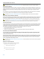
Icons
The following illustrations are used in this manual:
Note: notes give you extra information.
Warning: read the information carefully. It prevents you from making serious mistakes or from loosing information.
This illustration indicates actions you can perform with the mouse. Such as Altium Designer menu entries and dialogs.
Command line: type your input on the command line.
Reference: follow this reference to find related topics.
vii
TSK165x Embedded Tools Reference
Related Publications
MISRA−C
• Guidelines for the Use of the C Language in Vehicle Based Software [MIRA limited, 1998]
See also http://www.misra.org.uk
• MISRA−C:2004: Guidelines for the use of the C Language in critical systems [MIRA limited, 2004]
See also http://www.misra−c.com
TASKING Tools
• Using the TSK165x Embedded Tools
[Altium, GU0108]
• TSK165x RISC MCU Core Reference
[Altium, CR0114]
viii
1 Assembly Language
This chapter describes the most important aspects of the TASKING assembly
language and contains a detailed description of all built−in assembly functions and
assembler directives. For a complete overview of the architecture you are using and
a description of the assembly instruction set, refer to the target’s Core Reference
Manual.
Summary
1.1
Assembly Syntax
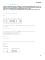
An assembly program consists of zero or more statements. A statement may optionally be followed by a comment. Any source
statement can be extended to more lines by including the line continuation character (\) as the last character on the line. The
length of a source statement (first line and continuation lines) is only limited by the amount of available memory.
Mnemonics and directives are case insensitive. Labels, symbols, directive arguments, and literal strings are case sensitive.
The syntax of an assembly statement is:
[label[:]] [instruction | directive | macro_call] [;comment]
label
A label is a special symbol which is assigned the value and type of the current program location counter. A label
can consist of letters, digits and underscore characters (_). The first character cannot be a digit. A label which is
prefixed by whitespace (spaces or tabs) has to be followed by a colon (:). The size of an identifier is only limited
by the amount of available memory.
Examples:
LAB1:
LAB1
instruction
;
;
;
;
This label is followed by a colon and
can be prefixed by whitespace
This label has to start at the beginning
of a line
An instruction consists of a mnemonic and zero, one or more operands. It must not start in the first column.
Operands are described in section 1.3, Operands of an Assembly Instruction. The instructions are described in
the target’s Core Reference Manual.
The instruction can also be a so−called ’generic instruction’. Generic instructions are pseudo instructions (no
instructions from the instruction set). Depending on the situation in which a generic instruction is used, the
assembler replaces the generic instruction with appropriate real assembly instruction(s). For a complete list, see
section 1.11, Generic Instructions.
directive
With directives you can control the assembler from within the assembly source. Except for preprocessing
directives, these must not start in the first column. Directives are described in section 1.8, Assembler Directives.
macro_call
A call to a previously defined macro. It must not start in the first column. See section 1.9 Macro Operations.
comment
Comment, preceded by a ; (semicolon).
You can use empty lines or lines with only comments.
1−1
TSK165x Embedded Tools Reference
1.2
Assembler Significant Characters
You can use all ASCII characters in the assembly source both in strings and in comments. Also the extended characters from
the ISO 8859−1 (Latin−1) set are allowed.
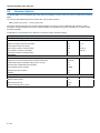
Some characters have a special meaning to the assembler. Special characters associated with expression evaluation are
described in section 1.6.3, Expression Operators. Other special assembler characters are:
Character
Description
;
Start of a comment
\
Line continuation character or
Macro operator: argument concatenation
?
Macro operator: return decimal value of a symbol
%
Macro operator: return hex value of a symbol
^
Macro operator: override local label
"
Macro string delimiter or
Quoted string .DEFINE expansion character
’
String constants delimiter
@
Start of a built−in assembly function
$
Location counter substitution
[ ]
Substring delimiter
Note that macro operators have a higher precedence than expression operators.
1.3
Operands of an Assembly Instruction
In an instruction, the mnemonic is followed by zero, one or more operands. An operand has one of the following types:
Operand
Description
symbol
A symbolic name as described in section 1.4, Symbol Names. Symbols can also occur in expressions.
register
Any valid register as listed in section 1.5, Registers.
expression
Any valid expression as described in section 1.6, Assembly Expressions.
address
A combination of expression, register and symbol.
1.4
Symbol Names
User−defined symbols
A user−defined symbol can consist of letters, digits and underscore characters (_). The first character cannot be a digit. The size
of an identifier is only limited by the amount of available memory. The case of these characters is significant. You can define a
symbol by means of a label declaration or an equate or set directive.
Labels
Symbols used for memory locations are referred to as labels.
Reserved symbols
Symbol names and other identifiers beginning with a period (.) are reserved for the system (for example for directives or section
names). Instructions and names of core processor registers are also reserved. The case of these built−in symbols is
insignificant.
1−2
Assembly Language
Examples
Valid symbol names:
loop_1
ENTRY
a_B_c
_aBC
Invalid symbol names:
1_loop
(starts with a number)
.DEFINE
(reserved directive name)
1.5
Registers
The following register names, either upper or lower case, should not be used for user−defined symbol names in an assembly
language source file:
TSK165x registers
F
W
PC8
The following special function registers should also not be used as symbol names in an assembly language source file. However
it is allowed to redefine them.
TSK165x special function registers
INDF
C
RA0
RB0
RC0
1.6
TMR0
DC
RA1
RB1
RC1
PCL
Z
RA2
RB2
RC2
STATUS
PD
RA3
RB3
RC3
FSR
TO
PORTA
PA0
PORTB
PA1
PORTC
RB4
RC4
RB5
RC5
RB6
RC6
RB7
RC7
Assembly Expressions
An expression is a combination of symbols, constants, operators, and parentheses which represent a value that is used as an
operand of an assembler instruction (or directive).
Expressions may contain user−defined labels (and their associated integer values), and any combination of integers or ASCII
literal strings.
Expressions follow the conventional rules of algebra and boolean arithmetic.
Expressions that can be evaluated at assembly time are called absolute expressions. Expressions where the result is unknown
until all sections have been combined and located, are called relocatable or relative expressions.
When any operand of an expression is relocatable, the entire expression is relocatable. Relocatable expressions are emitted in
the object file and evaluated by the linker.
The assembler evaluates expressions with 64−bit precision in two’s complement.
The syntax of an expression can be any of the following:
−
numeric contant
−
string
−
symbol
−
expression binary_operator expression
−
unary_operator expression
−
( expression )
−
function call
All types of expressions are explained in separate sections.
1−3
TSK165x Embedded Tools Reference
1.6.1
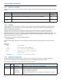
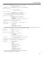
Numeric Constants
Numeric constants can be used in expressions. If there is no prefix, by default the assembler assumes the number is a decimal
number.
Base
Description
Example
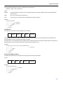
Binary
A 0b prefix followed by binary digits (0,1). Or use a b suffix
0b1101
11001010b
Hexadecimal
A 0x prefix followed by a hexadecimal digits (0−9, A−F, a−f). Or use a h suffix
0x12FF
0x45
0fa10h
Decimal,
integer
Decimal digits (0−9).
12
1245
Table 1−1: Numeric constants
1.6.2
Strings
ASCII characters, enclosed in single (’) or double (″) quotes constitue an ASCII string. Strings between double quotes allow
symbol substitution by a .DEFINE directive, whereas strings between single quotes are always literal strings. Both types of
strings can contain escape characters.
Strings constants in expressions are evaluated to a number (each character is replaced by its ASCII value). Strings in
expressions can have a size of up to 4 characters or less depending on the operand of an instruction or directive; any
subsequent characters in the string are ignored. In this case the assembler issues a warning. An exception to this rule is when a
string is used in a .DB, .DH, .DW or .DL assembler directive; in that case all characters result in a constant value of the
specified size. Null strings have a value of 0.
Square brackets ([ ]) delimit a substring operation in the form:
[string,offset,length]
offset is the start position within string. length is the length of the desired substring. Both values may not exceed the size of
string.
Examples
’ABCD’
; (0x41424344)
’’’79’
; to enclose a quote double it
"A\"BC"
; or to enclose a quote escape it
’AB’+1
; (0x4143) string used in expression
’’
; null string
[’TASKING’,0,4]
; results in the substring ’TASK’
1.6.3
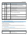
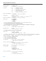
Expression Operators
The next table shows the assembler operators. They are ordered according to their precedence. Operators of the same
precedence are evaluated left to right. Parenthetical expressions have the highest priority (innermost first).
Valid operands include numeric constants, literal ASCII strings and symbols.
Type
Unary
1−4
Oper
ator
Name
Description
()
parenthesis
Expressions enclosed by parenthesis are evaluated first.
+
plus
Returns the value of its operand.
−
minus
Returns the negative of its operand.
~
complement
Returns complement, integer only
!
logical negate
Returns 1 if the operands’ value is 0; otherwise 0. For example, if buf is 0 then
!buf is 1.
Assembly Language
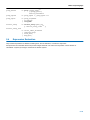
Type
Oper
ator
Arithmetic
Shift
Relational
Bitwise
Logical
Name
Description
*
multiplication
Yields the product of two operands.
/
division
Yields the quotient of the division of the first operand by the second.
With integers, the divide operation produces a truncated integer.
%
modulo
Integer only: yields the remainder from a division of the first operand by the
second.
+
addition
Yields the sum of its operands.
−
subtraction
Yields the difference of its operands.
<<
shift left
Integer only: shifts the left operand to the left (zero−filled) by the number of bits
specified by the right operand.
>>
shift right
Integer only: shifts the left operand to the right (sign bit extended) by the number
of bits specified by the right operand.
<
less than
<=
less or equal
>
greater than
an integer 1 if the indicated condition is TRUE.
>=
greater or equal
an integer 0 if the indicated condition is FALSE.
==
equal
!=
not equal
&
AND
Integer only: yields bitwise AND
|
OR
Integer only: yields bitwise OR
^
exclusive OR
Integer only: yields bitwise exlusive OR
logical AND
Returns an integer 1 if both operands are non−zero; otherwise, it returns an
integer 0.
||
logical OR
Returns an integer 1 if either of the operands is non−zero; otherwise, it returns an
integer 1
.
Dot
Singles out a bit number using the syntax: byte.bitpos
&&
Dot
Returns:
Table 1−2: Assembly expression operators
1.7
Built−in Assembly Functions
The TASKING assemblers have several built−in functions to support data conversion, string comparison, and math
computations. You can use functions as terms in any expression.
Syntax of an assembly function
@function_name([argument[,argument]...])
Functions start with ’@’ character and have zero or more arguments, and are always followed by opening and closing
parentheses. White space (a blank or tab) is not allowed between the function name and the opening parenthesis and between
the (comma−separated) arguments.
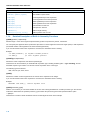
1.7.1
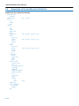
Overview of Built−in Assembly Functions
The following table provides an overview of all built−in assembly functions. Next all functions are described into more detail. expr
can be any assembly expression resulting in an integer value. Expressions are explained in section 1.6, Assembly Expressions.
Overview of assembly functions
Function
Description
@ARG(’symbol’|expr)
Test whether macro argument is present
@CAST(type,expr)
Cast result of expr to type
@CNT()
Return number of macro arguments
1−5
TSK165x Embedded Tools Reference
Function
Description
@CPU(string)
Test if current CPU matches string
@DEFINED(’symbol’|symbol)
Test whether symbol exists
@LSB(expr)
Least significant byte of the expression
@LSW(expr)
Least significant word of the expression
@MSB(expr)
Most significant byte of the expression
@MSW(expr)
Most significant word of the expression
@STRCAT(str1,str2)
Concatenate str1 and str2
@STRCMP(str1,str2)
Compare str1 with str2
@STRLEN(str)
Return length of string
@STRPOS(str1,str2[,start])
Return position of str1 in str2
1.7.2
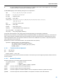
Detailed Description of Built−in Assembly Functions
@ARG(’symbol’ | expression)
Returns integer 1 if the macro argument represented by symbol or expression is present, 0 otherwise.
You can specify the argument with a symbol name (the name of a macro argument enclosed in single quotes) or with expression
(the ordinal number of the argument in the macro formal argument list).
If you use this function when macro expansion is not active, the assembler issues a warning.
Example:
.IF @ARG(’TWIDDLE’) ;is argument twiddle present?
.IF @ARG(1)
;is first argument present?
@CAST(type,expression)
Returns the result of expression, but with the specified type.
This function can be useful when you assemble with expression type−checking enabled (option −−type−checking), and the
assembler reports a type conflict. You can then cast the expression to the correct type.
The following types are allowed:
data, code, bit, byte, word, dword
@CNT()
Returns the number of macro arguments of the current macro expansion as an integer.
If you use this function when macro expansion is not active, the assembler issues a warning.
Example:
ARGCOUNT .SET @CNT() ; reserve argument count
@CPU(’processor_type’)
With the @CPU function you can check whether the source code is being assembled for a certain processor type. The function
evaluates to TRUE when the specified processor_type matches the processor type that was specified with the option
−−cpu=cpu.
This function is useful to create conditional code for several targets as shown in the example.
1−6
Assembly Language
Example:
.IF @CPU(’tsk165a’)
; true if you specified option −−cpu=tsk165a
... ; code for the TSK165A
.ELIF @CPU(’tsk165b’) ; true if you specified option −−cpu=tsk165b
... ; code for the TSK165B
.ELSE
... ; code for other processor types
.ENDIF
Assembler option −−cpu (Select CPU) in section 2.1, Assembler Options, of Chapter Tool Options.
@DEFINED(’symbol’ | symbol)
Returns 1 if symbol has been defined, 0 otherwise. If symbol is quoted, it is looked up as a .DEFINE symbol; if it is not quoted, it
is looked up as an ordinary symbol, macro or label.
Example:
.IF @DEFINED(’ANGLE’)
.IF @DEFINED(ANGLE)
;is symbol ANGLE defined?
;does label ANGLE exist?
@LSB(expression)
Returns the least significant byte of the result of the expression.
The result of the expression is calculated as 16 bits.
@LSW(expression)
Returns the least significant word (bits 0..15) of the result of the expression.
The result of the expression is calculated as a long (32 bits).
@MSB(expression)
Returns the most significant byte of the result of the expression.
The result of the expression is calculated as16 bits.
@MSW(expression)
Returns the most significant word (bits 16..31) of the result of the expression.
The result of the expression is calculated as a long (32 bits).
@STRCAT(string1,string2)
Concatenates string1 and string2 and returns them as a single string.
You must enclose string1 and string2 either with single quotes or with double quotes.
Example:
.DEFINE ID "@STRCAT(’TAS’,’KING’)"
; ID = ’TASKING’
@STRCMP(string1,string2)
Compares string1 with string2 by comparing the characters in the string. The function returns the difference between the
characters at the first position where they disagree, or zero when the strings are equal:
<0
if string1 < string2
0
if string1 == string2
>0
if string1 > string2
Example:
.IF (@STRCMP(STR,’MAIN’))==0
; does STR equal ’MAIN’?
1−7
TSK165x Embedded Tools Reference
@STRLEN(string)
Returns the length of string as an integer.
Example:
SLEN SET @STRLEN(’string’)
; SLEN = 6
@STRPOS(string1,string2[,start])
Returns the position of string2 in string1 as an integer. If string2 does not occur in string1, the last string postition + 1 is returned.
With start you can specify the starting position of the search. If you do not specify start, the search is started from the beginning
of string1.
Example:
ID .set @STRPOS(’TASKING’,’ASK’)
ID .set @STRPOS(’TASKING’,’BUG’)
1.8
; ID = 1
; ID = 7
Assembler Directives
An assembler directive is simply a message to the assembler. Assembler directives are not translated into machine instructions,
but can produce data. There are three types of assembler directives.
• Assembler directives that tell the assembler how to go about translating instructions into machine code. This is the most
typical form of assembly directives. Typically they tell the assembler where to put a program in memory, what space to
allocate for variables, and allow you to initialize memory with data. When the assembly source is assembled, a location
counter in the assembler keeps track of where the code and data is to go in memory.
The following directives fall under this group:
−
Assembly control directives
−
Symbol definition directives
−
Data definition / Storage allocation directives
−
HLL directives
−
Structure control statements
• Directives that are interpreted by the macro preprocessor. These directives tell the macro preprocessor how to manipulate
your assembly code before it is actually being assembled. You can use these directives to write macros and to write
conditional source code. Parts of the code that do not match the condition, will not be assembled at all. Unlike other
directives, preprocesssor directives can start in the first column.
• Some directives act as assembler options and most of them indeed do have an equivalent assembler (command line) option.
The advantage of using a directive is that with such a directive you can overrule the assembler option for a particular part of
the code. A typical example is to tell the assembler with an option to generate a list file while with the directives .NOLIST
and .LIST you overrule this option for a part of the code that you do not want to appear in the list file. Directives of this kind
sometimes are called controls.
Each assembler directive has its own syntax. Some assembler directives can be preceded with a label. If you do not precede an
assembler directive with a label, you must use white space instead (spaces or tabs). You can use assembler directives in the
assembly code as pseudo instructions.
1.8.1
Overview of Assembler Directives
The following tables provide an overview of all assembler directives. For a detailed description of these directives, refer to
section 1.8.2, Detailed Description of Assembler Directives.
Overview of assembly control directives
Directive
Description
.END
Indicates the end of an assembly module
.INCLUDE
Include file
.MESSAGE
Programmer generated message
1−8
Assembly Language
Overview of symbol definition directives
Directive
Description
.EQU
Set permanent value to a symbol
.EXTERN
Import global section symbol
.GLOBAL
Declare global section symbol
.LABEL
Define a label of specified type
.RESUME
Resume a previously defined section
.SECTION
Start a new section
.SET
Set temporary value to a symbol
.WEAK
Mark a symbol as ’weak’
Overview of data definition / storage allocation directives
Directive
Description
.ALIGN
Align location counter
.BS/.BSBIT/.BSB/
.BSW/.BSL
Define block storage (initialized)
.DBIT
Define bit
.DB
Define byte
.DH
Define half word
.DW
Define word
.DL
Define long word
.DS/.DSBIT/.DSB/
.DSW/.DSL
Define storage
.OFFSET
Move location counter forwards
Overview of macro and conditional assembly directives
Directive
Description
.DEFINE
Define substitution string
.BREAK
Break out of current macro expansion
.REPEAT/.ENDREP
Repeat sequence of source lines
.FOR/.ENDFOR
Repeat sequence of source lines n times
.IF/.ELIF/.ELSE
Conditional assembly directive
.ENDIF
End of conditional assembly directive
.MACRO/.ENDM
Define macro
.UNDEF
Undefine .DEFINE symbol or macro
Overview of listing control assembly directives
Directive
Description
.LIST/.NOLIST
Print / do not print source lines to list file
.PAGE
Set top of page/size of page
.TITLE
Set program title in header of assembly list file
Overview of HLL directives
Directive
Description
.CALLS
Pass call tree information
1−9
TSK165x Embedded Tools Reference
Overview of structured control statement directive
Directive
Description
.GEN
Generate assembly instruction(s) for structured control statements
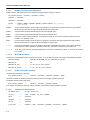
1.8.2
Detailed Description of Assembler Directives
.ALIGN
Syntax
.ALIGN expression
Description
With the .ALIGN directive you tell the assembler to align the location counter.
When the assembler encounters the .ALIGN directive, it moves the location counter forwards to an address that is aligned as
specified by expression and places the next instruction or directive on that address. The alignment is in minimal addressable
units (MAUs). The assembler fills the ’gap’ with NOP instructions. If the location counter is already aligned on the specified
alignment, it remains unchanged. The location of absolute sections will not be changed.
The expression must be a power of two: 2, 4, 8, 16, ... If you specify another value, the assembler changes the alignment to the
next higher power of two and issues a warning.
In bit−type sections expression is in number of bits.
Examples
.SECTION code,
.ALIGN 16
;
instruction ;
;
code
the assembler aligns
this instruction at 16 MAUs and
fills the ’gap’ with NOP instructions.
.SECTION code,
.ALIGN 12
;
instruction ;
;
code
WRONG: not a power of two, the
assembler aligns this instruction at
16 MAUs and issues a warning.
1−10
Assembly Language
.BREAK
Syntax
.BREAK
Description
The .BREAK directive causes immediate termination of a macro expansion, a .FOR loop exansion or a .REPEAT loop
expansion. In case of nested loops or macros, the .BREAK directive returns to the previous level of expansion.
The .BREAK directive is, for example, useful in combination with the .IF directive to terminate expansion when error conditions
are detected.
Example
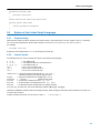
.FOR MYVAR IN 10 TO 20
...
;
...
; assembly source lines
...
;
.IF MYVAR > 15
.BREAK
.ENDIF
.ENDREP
1−11
TSK165x Embedded Tools Reference
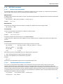
.BS/.BSBIT/.BSB/.BSH/.BSW/.BSL
Syntax
[label] .BS expression1[,expression2]
[label] .BSBIT expression1[,expression2]
[label] .BSB expression1[,expression2]
[label] .BSH expression1[,expression2]
[label] .BSW expression1[,expression2]
[label] .BSL expression1[,expression2]
Description
With the .BS directive (Block Storage) the assembler reserves a block of memory. The reserved block of memory is initialized to
the value of expression2, or zero if omitted.
With expression1 you specify the number of minimum addressable units (MAUs) you want to reserve, and how much the
location counter will advance. The expression must be an integer greater than zero and cannot contain any forward references
to address labels (labels that have not yet been defined).
In a bit−type section, the MAU size is 1, the .BS directive initializes a number of bits equal to the result of the expression.
With expression2 you can specify a value to initialize the block with. Only the least significant MAU of expression2 is used. If
you omit expression2, the default is zero.
If you specify label, it gets the value of the location counter at the start of the directive processing.
Initialization of a block of memory only happens in sections with section attribute init or romdata. In other sections, the
assembler issues a warning and only reserves space, just as with .DS.
The .BSBIT, .BSB, .BSH, .BSW and .BSL directives are variants of the .BS directive:
.BSBIT
The expression1 argument specifies the number of bits to reserve. You can only use this directive in sections of
type bit.
.BSB
The expression1 argument specifies the number of bytes to reserve. In a bit−type section, the .BSB directive still
initializes 8 bits.
.BSH
Same as the .BSB directive.
.BSW
The expression1 argument specifies the number of words to reserve (one word is 16 bits). In a bit−type section,
the .BSW directive still initializes 16 bits.
.BSL
The expression1 argument specifies the number of longs to reserve (one long is 32 bits). In a bit−type section, the
.BSL directive still initializes 32 bits.
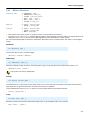
Example
The .BSB directive is for example useful to define and initialize an array that is only partially filled:
.section data, data, init
.DB 84,101,115,116 ; initialize 4 bytes
.BSB 96,0xFF
; reserve another 96 bytes, initialized with 0xFF
Related information
.DS
1−12
(Define Storage)
Assembly Language
.CALLS
Syntax
.CALLS ’caller’, ’callee’
Description
With this directive you indicate that a function caller calls another function callee.
The linker uses the .CALLS information to build a call graph.
Example
.CALLS ’_main’,’_nfunc’
Indicates that the function _main calls the function _nfunc
1−13
TSK165x Embedded Tools Reference
.DB
Syntax
[label] .DB argument[,argument]...
Description
With the .DB directive (Define Byte) the assembler allocates and initializes one byte of memory for each argument.
An argument can be:
• a single or multiple character string constant
• an integer expression
• NULL (indicated by two adjacent commas: ,,)
If you specify label, it gets the value of the location counter at the start of the directive processing.
Multiple arguments are stored in successive address locations. If an argument is NULL, its corresponding address location is
flled with zeros.
Integer arguments are stored as is, but must be byte values (within the range 0−255); floating−point numbers are not allowed. If
the evaluated expression is out of the range [−256, +255] the assembler issues an error. For negative values within that range,
the assembler adds 256 to the specified value (for example, −254 is stored as 2).
In case of single and multiple character strings, each character is stored in consecutive bytes whose lower seven bits represent
the ASCII value of the character. The standard C escape sequences are allowed:
.DB ’R’
.DB ’AB’,,’D’
; = 0x52
; = 0x41420043 (second argument is empty)
When you use the .DB directive in a bit−type section, each argument initializes 8 bits, and the location counter of the
current section is incremented with 8 bits.
When you use the .DB directive in a code section, this is translated into RETLW instructions.
Example
TABLE:
CHARS:
.DB 14,253,0x62,’ABCD’
.DB ’A’,’B’,,’C’,’D’
Related information
.BS (Block Storage)
.DS (Define Storage)
.DBIT (Define Bit)
.DH (Define Half Word)
.DW (Define Word)
.DL (Define Long)
1−14
Assembly Language
.DBIT
Syntax
[label] .DBIT argument[,argument]...
Description
With the .DBIT directive (Define Bit) you allocate and initialize memory in bit units for each argument.
You can use the .DBIT directive only within sections of the type bit.
An argument is 0 or 1.
If you specify label, it gets the value of the location counter at the start of the directive processing.
Example
NBITS:
.DBIT 1,0,1,1
; allocate and initialize four bits
Related information
.BS (Block Storage)
.DS (Define Storage)
.DB (Define Byte)
.DH (Define Half Word)
.DW (Define Word)
.DL (Define Long)
.SECTION (Start a new section)
1−15
TSK165x Embedded Tools Reference
.DEFINE
Syntax
.DEFINE symbol string
Description
With the .DEFINE directive you define a substitution string that you can use on all following source lines. The assembler
searches all succeeding lines for an occurrence of symbol, and replaces it with string. If the symbol occurs in a double quoted
string it is also replaced. Strings between single quotes are not expanded.
This directive is useful for providing better documentation in the source program. A symbol can consist of letters, digits and
underscore characters (_), and the first character cannot be a digit.
The assembler issues a warning if you redefine an existing symbol.
Example
Suppose you defined the symbol LEN with the substitution string "32":
.DEFINE LEN "32"
Then you can use the symbol LEN for example as follows:
.DS LEN
.MESSAGE I "The length is: LEN"
The assembler preprocessor replaces LEN with 32" and assembles the following lines:
.DS 32
.MESSAGE I "The length is: 32"
Related information
.UNDEF (Undefine a .DEFINE symbol or macro)
.MACRO/.ENDM (Define a macro)
1−16
Assembly Language
.DH
Syntax
[label] .DH argument[,argument]...
Description
With the .DH directive (Define Half Word) you allocate and initialize a half word of memory for each argument.
A half word is 8 bits (byte), so the .DH directive is the same as the .DB directive.
An argument is:
• a single or multiple character string constant
• an expression
• NULL (indicated by two adjacent commas: ,,)
If you specify label, it gets the value of the location counter at the start of the directive processing.
Multiple arguments are stored in successive half word address locations. If an argument is NULL, its corresponding address
location is filled with zeros.
Integer arguments are stored as is, but must be byte values (within the range 0−255); floating−point numbers are not allowed. If
the evaluated expression is out of the range [−256, +255] the assembler issues an error. For negative values within that range,
the assembler adds 256 to the specified value (for example, −254 is stored as 2).
In case of single and multiple character strings, each character is stored in consecutive bytes whose lower seven bits represent
the ASCII value of the character. The standard C escape sequences are allowed:
.DH ’AB’,,’D’ => 0x41
0x42
0x00 (second argument is empty)
0x44
When you use the .DH directive in a bit−type section, each argument initializes 8 bits, and the location counter of the
current section is incremented with the same number of bits.
When you use the .DH directive in a code section, this is translated into RETLW instructions.
Example
TABLE:
CHARS:
.DH 14,253,0x62,’ABCD’
.DH ’A’,’B’,,’C’,’D’
Related information
.BS (Block Storage)
.DS (Define Storage)
.DBIT (Define Bit)
.DB (Define Byte)
.DW (Define Word)
.DL (Define Long)
1−17
TSK165x Embedded Tools Reference
.DL
Syntax
[label] .DL argument[,argument]...
Description
With the .DL directive (Define Long) you allocate and initialize four bytes of memory for each argument.
An argument is:
• a single or multiple character string constant
• an expression
• NULL (indicated by two adjacent commas: ,,)
If you specify label, it gets the value of the location counter at the start of the directive processing.
Multiple arguments are stored in sets of four bytes. If an argument is NULL, its corresponding address locations are flled with
zeros.
Long arguments are stored as is. Floating−point values are not allowed.
If the evaluated argument is too large to be represented in a long, the assembler issues an error and truncates the value.
In case of character strings, each character is stored in the least significant byte of a long whose lower seven bits represent the
ASCII value of the character:
.DL ’AB’,,’D’ => 0x00000041
0x00000042
0x00000000 (second argument is empty)
0x00000044
When you use the .DL directive in a bit−type section, each argument initializes 32 bits, and the location counter of the
current section is incremented with the same number of bits.
Example
TABLE:
CHARS:
.DL 14,253,0x62,’ABCD’
.DL ’A’,’B’,,’C’,’D’
Related information
.BS (Block Storage)
.DS (Define Storage)
.DBIT (Define Bit)
.DB (Define Byte)
.DH (Define Half Word)
.DW (Define Word)
1−18
Assembly Language
.DS/.DSBIT/.DSB/.DSH/.DSW/.DSL
Syntax
[label] .DS expression
[label] .DSBIT expression
[label] .DSB expression
[label] .DSH expression
[label] .DSW expression
[label] .DSL expression
Description
With the .DS directive (Define Storage) the assembler reserves a block of memory. The reserved block of memory is not
initialized to any value.
With the expression you specify the number of minimum addressable units (MAUs) that you want to reserve. The expression
must evaluate to an integer larger than zero and cannot contain references to symbols that are not yet defined in the assembly
source.
In a bit−type section, the MAU size is 1, the .DS directive reserves a number of bits equal to the result of the expression.
If you specify label, it gets the value of the location counter at the start of the directive processing.
You cannot use the .DS directive in sections with attribute init. If you need to reserve initialized space in an init section,
use the .BS directive instead.
The .DSBIT, .DSB, .DSH, .DSW and .DSL directives are variants of the .DS directive:
.DSBIT
The expression argument specifies the number of bits to reserve.
.DSB
The expression argument specifies the number of bytes to reserve. In a bit−type section, the .DSB directive still
reserves 8 bits.
.DSH
Same as the .DSB directive.
.DSW
The expression argument specifies the number of words to reserve (one word is 16 bits). In a bit−type section, the
.DSW directive still reserves16 bits.
.DSL
The expression argument specifies the number of longs to reserve (one long is 32 bits). In a bit−type section, the
.DSL directive still reserves 32 bits.
Example
RES:
.DS 5+3
; allocate 8 bytes
Related information
.BS (Block Storage)
.DBIT (Define Bit)
.DB (Define Byte)
.DH (Define Half Word)
.DW (Define Word)
.DL (Define Long)
1−19
TSK165x Embedded Tools Reference
.DW
Syntax
[label] .DW argument[,argument]...
Description
With the .DW directive (Define Word) you allocate and initialize one word of memory for each argument.
One word is 16 bits.
An argument is:
• a single or multiple character string constant
• an expression
• NULL (indicated by two adjacent commas: ,,)
If you specify label, it gets the value of the location counter at the start of the directive processing.
Multiple arguments are stored in sets of two bytes. If an argument is NULL, its corresponding address locations are flled with
zeros.
Word arguments are stored as is. Floating−point values are not allowed. If the evaluated argument is too large to be represented
in a word, the assembler issues a warning and truncates the value.
In case of character strings, each character is stored in the least significant byte of a word which represents the ASCII value of
the character:
.DW ’AB’,,’D’ => 0x0041
0x0042
0x0000 (second argument is empty)
0x0044
When you use the .DW directive in a bit−type section, each argument initializes 16 bits, and the location counter of the
current section is incremented with the same number of bits.
Example
TABLE:
CHARS:
.DW 14,253,0x62,’ABCD’
.DW ’A’,’B’,,’C’,’D’
Related information
.BS (Block Storage)
.DS (Define Storage)
.DBIT (Define Bit)
.DB (Define Byte)
.DH (Define Half Word)
.DL (Define Long)
1−20
Assembly Language
.END
Syntax
.END
Description
With the .END directive you tell the assembler that the end of the module is reached. If the assembler finds assembly source
lines beyond the .END directive, it ignores those lines and issues a warning.
Example
.section code, code
; source lines
.END
; End of assembly module
1−21
TSK165x Embedded Tools Reference
.EQU
Syntax
symbol .EQU expression
Description
With the .EQU directive you assign the value of expression to symbol permanently. Once defined, you cannot redefine the
symbol. With the .GLOBAL directive you can define the symbol global.
The expression can either be absolute or relocatable and cannot contain forward references. Normally, the defined symbol gets
the same type as the result of the expression. However, when the resulting expression has type none" the symbol gets no type
when the .EQU is used outside a section and it gets the type of the section when it is defined inside a section.
Example
MYSYMBOL1 .EQU
0x4000 ; gets no type
.SECTION code, code
_START:
.SECTION data, data
MYSYMBOL2 .EQU 0x4100 ; gets type data
MYSYMBOL3 .EQU _START
;
;
;
;
gets type of the expression:
because _START is defined in
a section with type CODE, the
symbol gets type CODE.
.END
You cannot redefine the used symbols.
Related information
.SET (Set temporary value to a symbol)
1−22
Assembly Language
.EXTERN
Syntax
.EXTERN symbol [:type] [,symbol [:type]]...
Description
With the .EXTERN directive you define an external symbol. It means that the symbol is referenced in the current module while it
is defined outside the current module.
You must define the symbols either outside any module or declare it as globally accessible within another module with the
.GLOBAL directive.
The type of the global symbol which is referenced with the .EXTERN directive is determined from its definition. The assembler
then uses the type information of the .EXTERN directive to check the symbol’s use: if the symbol does not fit the instruction’s
operand, the assembler issues a warning.
If you do not specify type, the assembler does not check the use of the specified symbol.
Each target has a specific set of types as described in the .SECTION (Start a new section) directive.
If you do not use the .EXTERN directive and the symbol is not defined within the current module, the assembler issues a
warning and inserts the .EXTERN directive.
Example
.EXTERN
AA,CC,DD
; defined elsewhere
.EXTERN
AA:DATA
; assembler checks for type
Related information
.GLOBAL (Declare global section symbol)
1−23
TSK165x Embedded Tools Reference
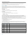
.FOR/.ENDFOR
Syntax
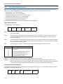
[label] .FOR var IN expression[,expression]...
....
.ENDFOR
or:
[label] .FOR var IN start TO end [STEP step]
....
.ENDFOR
Description
With the .FOR/.ENDFOR directive you can repeat a sequence of assembly source lines with an iterator. As shown by the
syntax, you can use the .FOR/.ENDFOR in two ways.
1. In the first mehod, the loop is repeated as many times as the number of arguments following IN. If you use the symbol var in
the assembly lines between .FOR and .ENDFOR, for each repetition the symbol var is substituted by a subsequent
expression from the argument list. If the argument is a null, then the loop is repeated with each occurrence of the symbol var
removed.
2. In the second method, the loop is repeated using the symbol var as a counter. The counter passes all integer values from
start to end with a step. If you do not specify step, the counter is increased by one for every repetition.
If you specify label, it gets the value of the location counter at the start of the directive processing.
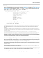
Example
In the following example the loop is repeated 4 times (there are four arguments). With the .DB directive you allocate and
initialize a byte of memory for each repetition of the loop (a word for the .DW directive). Effectively, the preprocessor duplicates
the .DB and .DW directives four times in the assembly source.
.FOR VAR1 IN 1,2+3,4,12
.DB VAR1
.DW (VAR1*VAR1)
.ENDFOR
In the following example the loop is repeated 16 times. With the .DL directive you allocate and initialize four bytes of memory for
each repetition of the loop. Effectively, the preprocessor duplicates the .DL directive16 times in the assembled file, and
substitutes VAR2 with the subsequent numbers.
.FOR VAR2 IN 1 to 0x10
.DL (VAR1*VAR1)
.ENDFOR
Related information
.REPEAT/.ENDREP (Repeat sequence of source lines)
1−24
Assembly Language
.GEN
Syntax
[label] .GEN structured−control−statement
for eample:
[label] .GEN FOR var = start {DOWNTO | TO} end [BY step]
....
.GEN ENDFOR
Description
With the .GEN directive you can generate the appropriate TSK165x assembly language instructions for the structured control
statement. You can use constructs like loops (FOR, WHILE, REPEAT), conditional control (IF/ELSE) or a C language alike
switch implementation (SWITCH).
Related information
For detailed information and examples see section 1.10, Structured Control Statements
1−25
TSK165x Embedded Tools Reference
.GLOBAL
Syntax
.GLOBAL symbol[,symbol]...
Description
All symbols or labels defined in the current section or module are local to the module by default. You can change this default
behavior with assembler option −ig.
With the .GLOBAL directive you declare one of more symbols as global. It means that the specified symbols are defined within
the current section or module, and that those definitions should be accessible by all modules.
The type of the global defined symbol is determined by its definition.
To access a symbol, defined with .GLOBAL, from another module, use the .EXTERN directive.
Only program labels and symbols defined with .EQU can be made global.
Example
LOOPA .EQU 1
.GLOBAL
LOOPA
; definition of symbol LOOPA
; LOOPA will be globally
; accessible by other modules
Related information
.EXTERN (Import global section symbol)
1−26
Assembly Language
.IF/.ELIF/.ELSE/.ENDIF
Syntax
.IF expression
.
.
[.ELIF expression]
.
.
[.ELSE]
.
.
.ENDIF
(the .ELIF directive is optional)
(the .ELSE directive is optional)
Description
With the .IF/.ENDIF directives you can create a part of conditional assembly code. The assembler assembles only the code
that matches a specified condition.
The expression must evaluate to an integer and cannot contain forward references. If expression evaluates to zero, the
IF−condition is considered FALSE, any non−zero result of expression is considered as TRUE.
You can nest .IF directives to any level. The .ELSE and .ELIF directive always refer to the nearest previous .IF directive.
Example
Suppose you have an assemble source file with specific code for a test version, for a demo version and for the final version.
Within the assembly source you define this code conditionally as follows:
.IF
TEST
... ; code for the test version
.ELIF DEMO
... ; code for the demo version
.ELSE
... ; code for the final version
.ENDIF
Before assembling the file you can set the values of the symbols TEST and DEMO in the assembly source before the .IF
directive is reached. For example, to assemble the demo version:
TEST .SET 0
DEMO .SET 1
You can also define the symbols in Altium Designer as preprocessor macros in dialog Project » Project Options » Assembler
» Preprocessing (assembler option −−define).
Related information
Assembler option −−define (Define preprocessor macro) in Section 2.1, Assembler Options, of Chapter Tool Options.
1−27
TSK165x Embedded Tools Reference
.INCLUDE
Syntax
.INCLUDE "filename" | <filename>
Description
With the .INCLUDE directive you include another file at the exact location where the .INCLUDE occurs. This happens before
the resulting file is assembled. The .INCLUDE directive works similarly to the #include statement in C. The source from the
include file is assembled as if it followed the point of the .INCLUDE directive. When the end of the included file is reached,
assembly of the original file continues.
The string specifies the filename of the file to be included. The filename must be compatible with the operating system
(forward/backward slashes) and can contain a directory specification. If you omit a filename extension, the assembler assumes
the extension .asm.
If an absolute pathname is specified, the assembler searches for that file. If a relative path is specified or just a filename, the
order in which the assembler searches for include files is:
1. The current directory if you use the "filename" construction.
The current directory is not searched if you use the <filename> syntax.
2. The path that is specified with the assembler option −−include−directory (−I).
3. The path that is specified in the environment variable AStargetINC when the product was installed.
4. The default directory ...\ctarget\include.
Example
Suppose that your assembly source file test.src contains the following line:
.INCLUDE "c:\myincludes\myinc.inc"
The assembler issues an error if it cannot find the file at the specified location.
.INCLUDE "myinc.inc"
The assembler searches the file myinc.inc according to the rules described above.
Related information
Assembler option −−include−directory (Add directory to include file search path) in Section 2.1, Assembler Options, of
Chapter Tool Options.
1−28
Assembly Language
.LABEL
Syntax
label .LABEL type
Description
With the .LABEL directive you define a label of a specified type.
Use this directive if the label that you define, must have another type than it receives by default. By default, a label inherits its
type from the type of the section in which you define the label.
Example
In the next example, the first label receives the type of the section. The second label is defined with the .LABEL directive and
receives the type data.
mylabel1
mylabel2
.SECTION code, code
.EQU 2
.LABEL data
1−29
TSK165x Embedded Tools Reference
.LIST/.NOLIST
Syntax
.NOLIST
.
. ; assembly source lines
.
.LIST
Description
If you generate a list file (see assembler option −−list−file), you can use the .LIST and .NOLIST directives to specify which
source lines the assembler must write to the list file.
The assembler prints all source lines to the list file, untill it encounters a .NOLIST directive. The assembler does not print the
.NOLIST directive and subsequent source lines. When the assembler encounters the .LIST directive, it resumes printing to the
list file, starting with the .LIST directive itself.
It is possible to nest the .LIST/.NOLIST directives.
Example
Suppose you assemble the following assembly code with the assembler option −−list−file:
.SECTION code, code
... ; source line 1
.NOLIST
... ; source line 2
.LIST
... ; source line 3
.END
The assembler generates a list file with the following lines:
.SECTION code, code
... ; source line 1
.LIST
... ; source line 3
.END
Related information
Assembler option −−list−file (Generate list file) in Section 2.1, Assembler Options, of Chapter Tool Options.
1−30
Assembly Language
.MACRO/.ENDM
Syntax
macro_name .MACRO [argument[,argument]...]
...
macro_definition_statements
...
.ENDM
Description
With the .MACRO directive you define a macro. Macros provide a shorthand method for handling a repeated pattern of code or
group of instructions. You can define the pattern as a macro, and then call the macro at the points in the program where the
pattern would repeat.
The definition of a macro consists of three parts:
• Header, which assigns a name to the macro and defines the arguments.
• Body, which contains the code or instructions to be inserted when the macro is called.
• Terminator, which indicates the end of the macro definition (.ENDM directive).
The arguments are symbolic names that the macro processor replaces with the literal arguments when the macro is expanded
(called). Each formal argument must follow the same rules as symbol names: the name can consist of letters, digits and
underscore characters (_). The first character cannot be a digit. Argument names cannot start with a percent sign (%).
Macro definitions can be nested but the nested macro will not be defined until the primary macro is expanded.
You can use the following operators in macro definition statements:
Operator
Name
Description
\
Macro argument
concatenation
Concatenates a macro argument with adjacent alphanumeric characters.
?
Return decimal
value of symbol
Substitutes the ?symbol sequence with a character string that represents the decimal value
of the symbol.
%
Return hex
value of symbol
Substitutes the %symbol sequence with a character string that represents the hexadecimal
value of the symbol.
"
Macro string
delimiter
Allows the use of macro arguments as literal strings.
^
Macro local label
override
Prevents name mangling on labels in macros.
Example
The macro definition:
macro_a .MACRO arg1,arg2
.db arg1
.dw (arg1*arg2)
.ENDM
;header
;body
;terminator
The macro call:
.section macro_data,data,init
macro_a 2,3
The macro expands as follows:
.db 2
.dw (2*3)
1−31
TSK165x Embedded Tools Reference
Related information
.DEFINE (Define a substitution string)
Section 1.9, Macro Operations.
1−32
Assembly Language
.MESSAGE
Syntax
.MESSAGE type [{str|exp|symbol}[,{str|exp|symbol}]...]
Description
With the .MESSAGE directive you tell the assembler to print a message to stdout during the assembling process.
With type you can specify the following types of messages:
I
Information message. Error and warning counts are not affected and the assembler continues the assembling process.
W Warning message. Increments the warning count and the assembler continues the assembling process.
E Error message. Increments the error count and the assembler continues the assembling process.
F Fatal error message. The assembler immediately aborts the assembling process and generates no object file or list file.
The .MESSAGE directive is for example useful in combination with conditional assembly to indicate which part is assembled.
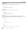
Example
.MESSAGE I ’Generating tables’
ID .EQU 4
.MESSAGE E ’The value of ID is ’,ID
.DEFINE LONG "SHORT"
.MESSAGE I ’This is a LONG string’
.MESSAGE I "This is a LONG string"
Within single quotes, the defined symbol LONG is not expanded. Within double quotes the symbol LONG is expanded so the
actual message is printed as:
This is a LONG string
This is a SHORT string
1−33
TSK165x Embedded Tools Reference
.OFFSET
Syntax
.OFFSET expression
Description
With the .OFFSET directive you tell the assembler to give the location counter a new offset relative to the start of the section.
When the assembler encounters the .OFFSET directive, it moves the location counter forwards to the specified address, relative
to the start of the section, and places the next instruction on that address. If you specify an address equal to or lower than the
current position of the location counter, the assembler issues an error.
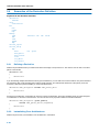
Example
.SECTION code, code
nop
nop
nop
.OFFSET 0x20
; the assembler places
nop
; this instruction at address 0x20
; relative to the start of the section.
.SECTION code, code
nop
nop
nop
.OFFSET 0x02
; WRONG: the current position of the
nop
; location counter is 0x03.
1−34
Assembly Language
.PAGE
Syntax
.PAGE [width,length,blanktop,blankbtm,blankleft]
Description
If you generate a list file (see assembler option −−list−file), you can use the .PAGE directive to format the generated list file.
width
Number of characters on a line (1−255). Default is 132.
length
Number of lines per page (10−255). Default is 66.
blanktop
Number of blank lines at the top of the page. Default = 0.
Specify a value so that blanktop + blankbtm ≤ length − 10.
blankbtm
Number of blank lines at the bottom of the page. Default = 0.
Specify a value so that blanktop + blankbtm ≤ length − 10.
blankleft
Number of blank columns at the left of the page. Default = 0. Specify a value smaller than width.
If you use the .PAGE directive without arguments, it causes a ’formfeed’: the next source line is printed on the next page in the
list file.
You can omit an argument by using two adjacent commas. If the remaining arguments after an argument are all empty, you can
omit them.
A label is not allowed with this directive.
Example
.PAGE
; formfeed, the next source line is printed
; on the next page in the list file.
.PAGE 96
; set pagewidth to 96. Note that you can
; omit the last four arguments
.PAGE ,,5
; insert five blank lines at the top. Note
; that you can omit the last two arguments.
Related information
.TITLE (Set program title in header of assembler list file)
Assembler option −−list−file (Generate list file) in Section 2.1, Assembler Options, of Chapter Tool Options.
1−35
TSK165x Embedded Tools Reference
.REPEAT/.ENDREP
Syntax
[label] .REPEAT expression
....
.ENDREP
Description
With the .REPEAT/.ENDREP directive you can repeat a sequence of assembly source lines. With expression you specify the
number of times the loop is repeated.
If you specify label, it gets the value of the location counter at the start of the directive processing.
Example
In this example the loop is repeated 3 times. Effectively, the preprocessor repeats the source lines (.DB 10) three times, then
the assembler assembles the result:
.REPEAT 3
.DB 10 ; assembly source lines
.ENDREP
Related information
.FOR/.ENDFOR (Repeat sequence of source lines n times)
1−36
Assembly Language
.RESUME
Syntax
.RESUME name [, type[, attribute]...]
Description
With the .SECTION directive you always start a new section. With the .RESUME directive you can reactivate a previously
defined section. See the .SECTION directive for a list of available section types and attributes. If you omit the type and attribute,
the previously defined section with the same name is reactivated (ignoring the type and attribute(s)). If you specify a type and
attribute you reactivate the section with that same type and attribute.
You cannot resume sections that have the group or overlay attribute. In this case the assembler issues a warning.
Example
.SECTION code, code
...
.SECTION data, data
...
.SECTION code, code
...
.SECTION data, data, init
...
.RESUME code
...
.RESUME data, data
...
.RESUME data, data, init
; First code section
; First data section
; Second code section
; Second data section
; Resume in the second code section
; Resume in the first data section
; Resume in the second data section
Related information
.SECTION (Start a new section)
1−37
TSK165x Embedded Tools Reference
.SECTION
Syntax
.SECTION name, type[, attribute]...
Description
With the .SECTION directive you define a new section. Each time you use the .SECTION directive, a new section is created. It
is possible to create multiple sections with exactly the same name.
To resume a previously defined section, use the .RESUME directive.
If you define a section, you must always specify the section name and type. Names starting with a dot ’.’ are reserved for the
system. Optionally, you can specify one or more attributes.
You can specify the following section types:
Section Type
Description
data
Data space (4 banks of 32 bytes)
code
Code address space
bit
Bit addressable data (data space)
Table 1−3: TSK165x section types
Sections of a specified type are located by the linker in a memory space that has the same name as the section type. The space
names are defined in a so−called ’linker script file’ (files with the extension .lsl) delivered with the product in the directory
\Program Files\Altium Designer\System\Tasking \include.lsl.
You can specify the following section attributes:
Attribute
Description
Allowed on
at(address)
Locate the section at the specified address
all
clear
Clear the DATA section at program startup
data, bit
noclear
Do not clear the DATA section at program startup (default)
all
init
Copies the data from the section from ROM to RAM at program setup.
data, bit
noinit
Do not initialize section (default)
all
inpage
Indicates that the section must fit within a 256 byte page.
all
max
When sections with the same name occur in different object modules, with the MAX
attribute, the linker generates a section of which the size is the maximum of the sizes
in the individual object modules.
data, bit
romdata
Indicates that the section contains data to be placed in ROM
code
group(’group’)
Used to group sections, for example for placing in the same page.
all
Table 1−4: TSK165x section attributes
Example
.SECTION data, data, init
; Declare section of type ’data’ and
; initialize it by copying
; its data from ROM
.SECTION data, data, clear
; Declare a data section,
; cleared at program startup
.SECTION data, data, init
; Declare a second data init section
.RESUME (Resume a previously defined section)
1−38
Assembly Language
.SET
Syntax
symbol
.SET expression
.SET symbol expression
Description
With the .SET directive you assign the value of expression to symbol temporarily. If a symbol was defined with the .SET
directive, you can redefine that symbol in another part of the assembly source, using the .SET directive again. Symbols that you
define with the .SET directive are always local: you cannot define the symbol global with the .GLOBAL directive.
The .SET directive is useful in establishing temporary or reusable counters within macros. expression must be absolute and
cannot include a symbol that is not yet defined (no forward references are allowed).
Normally, the defined symbol gets the same type as the result of the expression. However, when the resulting expression has
type "none", the symbol gets no type.
Example
COUNT
.SET
0
; Initialize count. Later on you can
; assign other values to the symbol
Related information
.EQU (Set a permanent value to a symbol)
1−39
TSK165x Embedded Tools Reference
.TITLE
Syntax
.TITLE [title]
Description
If you generate a list file (see assembler option −−list−file), you can use the .TITLE directive to specify the program title which
is printed at the top of each page in the assembler list file.
If you use the .TITLE directive without the argument, the title becomes empty. This is also the default. The specified title is valid
until the assembler encouters a new .TITLE directive.
Example
.TITLE "The best program"
In the header of each page in the assembler list file, the title of the progam is printed. In this case: The best program
Related information
.PAGE (Format the assembler list file)
Assembler option −−list−file (Generate list file) in Section 2.1, Assembler Options, of Chapter Tool Options.
1−40
Assembly Language
.UNDEF
Syntax
.UNDEF symbol
Description
With the .UNDEF directive you can undefine a substitution string that was previously defined with the .DEFINE directive. The
substitution string associated with symbol is released, and symbol will no longer represent a valid .DEFINE substitution.
The assembler issues a warning if you redefine an existing symbol.
Example
.UNDEF LEN
Undefines the LEN substitution string that was previously defined with the .DEFINE directive.
Related information
.DEFINE (Define substitution string)
1−41
TSK165x Embedded Tools Reference
.WEAK
Syntax
.WEAK symbol[,symbol]...
Description
With the .WEAK directive you mark one or more symbols as ’weak’. The symbol can be defined in the same module with the
.GLOBAL directive or the .EXTERN directive. If the symbol does not already exist, it will be created.
A ’weak’ external reference is resolved by the linker when a global (or weak) definition is found in one of the object files.
However, a weak reference will not cause the extraction of a module from a library to resolve the reference.
You can overrule a weak definition with a .GLOBAL definition in another module. The linker will not complain about the duplicate
definition, and ignore the weak definition.
Only program labels and symbols defined with .EQU can be made weak.
Example
LOOPA .EQU 1
.GLOBAL
LOOPA
.WEAK LOOPA
;
;
;
;
definition of symbol LOOPA
LOOPA will be globally
accessible by other modules
mark symbol LOOPA as weak
Related information
.EXTERN (Import global section symbol)
.GLOBAL (Declare global section symbol)
1−42
Assembly Language
1.9
Macro Operations
Macros provide a shorthand method for inserting a repeated pattern of code or group of instructions. You can define the pattern
as a macro, and then call the macro at the points in the program where the pattern would repeat.
Some patterns contain variable entries which change for each repetition of the pattern. Others are subject to conditional
assembly.
When a macro is called, the assembler executes the macro and replaces the call by the resulting in−line source statements.
’In−line’ means that all replacements act as if they are on the same line as the macro call. The generated statements may
contain substitutable arguments. The statements produced by a macro can be any processor instruction, almost any assembler
directive, or any previously−defined macro. Source statements resulting from a macro call are subject to the same conditions
and restrictions as any other statements.
Macros can be nested. The assembler processes nested macros when the outer macro is expanded.
1.9.1
Defining a Macro
The first step in using a macro is to define it.
The definition of a macro consists of three parts:
• Header, which assigns a name to the macro and defines the arguments.
• Body, which contains the code or instructions to be inserted when the macro is called.
• Terminator, which indicates the end of the macro definition (.ENDM directive).
A macro definition takes the following form:
macro_name .MACRO [arg[,arg]...] [; comment]
.
source statements
.
.ENDM
If the macro name is the same as an existing assembler directive or mnemonic opcode, the assembler replaces the directive or
mnemonic opcode with the macro and issues a warning.
The arguments are symbolic names that the macro preprocessor replaces with the literal arguments when the macro is
expanded (called). Each argument must follow the same rules as global symbol names. Argument names cannot start with a
percent sign (%).
Example
Consider the following macro definition:
MUL
.MACRO retval, arg1, arg2
CLRW
; w = 0;
MOVF arg2,0
BTFSC Z
goto ^end
; if (arg2)
^loop:
; do {
ADDWF arg1,0
;
w += arg1;
BTFSC C
;
if (carry)
INCF retval,1
;
res += 0x100;
DECFSZ arg2,1
; } while (arg2−−);
goto ^loop
^end:
MOVWF (retval + 1) ; res += w;
.ENDM
1−43
TSK165x Embedded Tools Reference
After the following macro call:
result .dsw 1
aval
.db 113
bval
.db 7
.section code, code
MUL result, aval, bval
.end
The macro expands to:
CLRW
MOVF bval,0
BTFSC Z
goto end
; w = 0;
; if (bval)
loop:
;
;
;
;
;
ADDWF aval,0
BTFSC C
INCF result,1
DECFSZ bval,1
goto loop
do {
w += aval;
if (carry)
res += 0x100;
} while (bval−−);
end:
MOVWF (result + 1) ; res += w;
1.9.2
Calling a Macro
To invoke a macro, construct a source statement with the following format:
[label] macro_name [arg[,arg...]]
[; comment]
where:
label
An optional label that corresponds to the value of the location counter at the start of the macro expansion.
macro_name The name of the macro. This may not start in the first column.
arg
One or more optional, substitutable arguments. Multiple arguments must be separated by commas.
comment
An optional comment.
The following applies to macro arguments:
• Each argument must correspond one−to−one with the formal arguments of the macro definition. If the macro call does not
contain the same number of arguments as the macro definition, the assembler issues a warning.
• If an argument has an embedded comma or space, you must surround the argument by single quotes (’).
• You can declare a macro call argument as null in three ways:
−
enter delimiting commas in succession with no intervening spaces
macroname ARG1,,ARG3 ; the second argument is a null argument
−
terminate the argument list with a comma, the arguments that normally would follow, are now considered null
macroname ARG1,
−
; the second and all following arguments are null
declare the argument as a null string
• No character is substituted in the generated statements that reference a null argument.
1−44
Assembly Language
1.9.3
Using Operators for Macro Arguments
The assembler recognizes certain text operators within macro definitions which allow text substitution of arguments during
macro expansion. You can use these operators for text concatenation, numeric conversion, and string handling.
Operator
Name
Description
\
Macro argument
concatenation
Concatenates a macro argument with adjacent alphanumeric characters.
?
Return decimal
value of symbol
Substitutes the ?symbol sequence with a character string that represents the decimal value
of the symbol.
%
Return hex
value of symbol
Substitutes the %symbol sequence with a character string that represents the hexadecimal
value of the symbol.
"
Macro string
delimiter
Allows the use of macro arguments as literal strings.
^
Macro local label
override
Prevents name mangling on labels in macros.
Example: Argument Concatenation Operator − \
Consider the following macro definition:
MAC_A .MACRO reg,val
bmov RB\reg,val
.ENDM
The macro is called as follows:
MAC_A 0,1
The macro expands as follows:
bmov RB0,1
The macro preprocessor substitutes the character ’0’ for the argument reg, and the character ’1’ for the argument val. The
concatenation operator (\) indicates to the macro preprocessor that the substitution characters for the arguments are to be
concatenated with the characters ’RB’.
Without the ’\’ operator the macro would expand as:
bmov RBreg,1
which results in an assembler error (invalid operand).
Example: Decimal Value Operator − ?
Instead of substituting the formal arguments with the actual macro call arguments, you can also use the value of the macro call
arguments.
Consider the following source code that calls the macro MAC_A after the argument AVAL has been set to 1.
AVAL .SET 1
MAC_A 0,AVAL
If you want to replace the argument val with the value of AVAL rather than with the literal string ’AVAL’, you can use the ?
operator and modify the macro as follows:
MAC_A .MACRO reg,val
bmov RB\reg,?val
.ENDM
1−45
TSK165x Embedded Tools Reference
Example: Hex Value Operator − %
The percent sign (%) is similar to the standard decimal value operator (?) except that it returns the hexadecimal value of a
symbol.
Consider the following macro definition:
GEN_LAB
.MACRO
LAB\%VAL STMT
.ENDM
LAB,VAL,STMT
The macro is called after NUM has been set to 10:
NUM .SET
GEN_LAB
10
HEX,NUM,NOP
The macro expands as follows:
HEXA NOP
The %VAL argument is replaced by the character ’A’ which represents the hexadecimal value 10 of the argument VAL.
Example: Argument String Operator − "
To generate a literal string, enclosed by single quotes (’), you must use the argument string operator (") in the macro definition.
Consider the following macro definition:
STR_MAC
.DB
.ENDM
.MACRO STRING
"STRING"
The macro is called as follows:
STR_MAC
ABCD
The macro expands as follows:
.DB
’ABCD’
Within double quotes .DEFINE directive definitions can be expanded. Take care when using constructions with quotes and
double quotes to avoid inappropriate expansions. Since .DEFINE expansion occurs before macro substitution, any .DEFINE
symbols are replaced first within a macro argument string:
.DEFINE LONG ’short’
STR_MAC
.MACRO STRING
.MESSAGE I ’This is a LONG STRING’
.MESSAGE I "This is a LONG STRING"
.ENDM
If the macro is called as follows:
STR_MAC
sentence
it expands as:
.MESSAGE I ’This is a LONG STRING’
.MESSAGE I ’This is a short sentence’
Macro Local Label Override Operator − ^
If you use labels in macros, the assembler normally generates another unique name for the labels (such as
LOCAL__M_L000001).
The macro ^−operator prevents name mangling on macro local labels.
Consider the following macro definition:
INIT .MACRO addr
LOCAL: movwf ^addr
.ENDM
1−46
Assembly Language
The macro is called as follows:
LOCAL:
INIT LOCAL
The macro expands as:
LOCAL__M_L000001: movwf LOCAL
If you would not have used the ^ operator, the macro preprocessor would choose another name for LOCAL because the label
already exists. The macro would expand like:
LOCAL__M_L000001: movwf LOCAL__M_L000001
1.9.4
Using the .FOR and .REPEAT Directives as Macros
The .FOR and .REPEAT directives are specialized macro forms to repeat a block of source statements. You can think of them
as a simultaneous definition and call of an unnamed macro. The source statements between the .FOR and .ENDFOR directives
and .REPEAT and .ENDREP directives follow the same rules as macro definitions.
For a detailed description of these directives, see section 1.8, Assembler Directives.
1.9.5
Conditional Assembly
With the conditional assembly directives you can instruct the macro preprocessor to use a part of the code that matches a
certain condition.
You can specify assembly conditions with arguments in the case of macros, or through definition of symbols via the .DEFINE,
.SET, and .EQU directives.
The built−in functions of the assembler provide a versatile means of testing many conditions of the assembly environment.
You can use conditional directives also within a macro definition to check at expansion time if arguments fall within a range of
allowable values. In this way macros become self−checking and can generate error messages to any desired level of detail.
The conditional assembly directive .IF/.ENDIF has the following form:
.IF expression
.
.
[.ELIF expression]
;(the .ELIF directive is optional)
.
.
[.ELSE]
;(the .ELSE directive is optional)
.
.
.ENDIF
A section of a program that is to be conditionally assembled must be bounded by an .IF−.ENDIF directive pair. If the optional
.ELSE and/or .ELIF directives are not present, then the source statements following the .IF directive and up to the next
.ENDIF directive will be included as part of the source file being assembled only if the expression had a non−zero result.
If the expression has a value of zero, the source file will be assembled as if those statements between the .IF and the .ENDIF
directives were never encountered.
If the .ELSE directive is present and expression has a nonzero result, then the statements between the .IF and .ELSE
directives will be assembled, and the statement between the .ELSE and .ENDIF directives will be skipped. Alternatively, if
expression has a value of zero, then the statements between the .IF and .ELSE directives will be skipped, and the statements
between the .ELSE and .ENDIF directives will be assembled.
1−47
TSK165x Embedded Tools Reference
1.10
Structured Control Statements
The assembly language provides an instruction set for performing certain rudimentary operations. These operations in turn may
be combined into control structures such as loops (FOR, REPEAT, WHILE) or conditional branches (IF−THEN,
IF−THEN−ELSE). The TSK165x assembler, however, accepts formal, high−level .GEN directives that specify these control
structures, generating the appropriate assembly language instructions for their efficient implementation. This use of structured
control statements improves the readability of assembly language programs, without compromising the desirable aspects of
programming in an assembly language.
The TSK165x assembler supports the following types of structured control statements by means of the .GEN directive:
•
•
•
•
•
For statement
While statement
Repeat statement
If statement
Switch statement
If an assembler directive occurs within a structured control statement, this is evaluated only once: at assembly time. So, an
assembler directive in a FOR, WHILE or REPEAT statement does not imply repeated occurrence of the directive.
See the description of the .GEN directive in section 1.8, Assembler Directives.
1.10.1 FOR Statement
Syntax
.GEN FOR var = start {DOWNTO|TO} end [BY step]
[.GEN BREAK]
[.GEN CONTINUE]
statements
.GEN ENDFOR
Registers/flags affected
W, C, Z, PA1, PA0
Description
With the FOR statement the assembler initializes var to start and performs the assembly statements until var is greater (TO) or
less than (DOWNTO) end. The user−defined operand var serves as the loop counter. The TO construct counts upwards and the
DOWNTO construct counts downwards. You can specify an increment/decrement step size by step. If you omit the BY clause the
default step size is #1.
var must be a writable address or symbol. start, end and step can be an address, symbol or immediate value. An immediate
operand must be preceded by a pound sign (#). Each address or symbol must be accessible in the current data page.
You can use the BREAK and/or CONTINUE statements inside a FOR statement.
If an assembler directive occurs within a structured control statement, this is evaluated only once: at assembly time. So,
an assembler directive in a FOR, WHILE or REPEAT statement does not imply repeated occurrence of the directive.
Example 1: Count upwards with step size
idx:
1−48
.SECTION data, data
.DSB 1
.SECTION code, code
.GEN FOR idx = #0 TO #128 BY #5
NOP ; Just do nothing...
.GEN ENDFOR
Assembly Language
Generated TSK165x code:
;
+
+
+__T121:
.GEN FOR idx = #0 TO #128 BY #5
MOVLW #0
MOVWF idx
CJGE idx,#128, __T122
NOP ; Just do nothing...
;
+
+
+
+__T122:
.GEN ENDFOR
MOVLW #5
ADDWF idx,f
GOTO __T121
Example 2: Count downwards
.SECTION data, data
.DSB 1
.SECTION code, code
.GEN FOR idx = #255 DOWNTO #128
NOP ; Just do nothing...
.GEN ENDFOR
idx:
Generated TSK165x code:
;
+
+
+__T123:
.GEN FOR idx = #255 DOWNTO #128
MOVLW #255
MOVWF idx
CJLE idx,#128, __T124
NOP ; Just do nothing...
;
.GEN ENDFOR
+
DECWF idx,f
+
GOTO __T123
+__T124:
Related information
BREAK Statement
CONTINUE Statement
REPEAT Statement
WHILE Statement
.FOR/.ENDFOR (Repeat sequence of source lines n times)
1.10.2 WHILE Statement
Syntax
.GEN WHILE expression
[.GEN BREAK]
[.GEN CONTINUE]
statements
.GEN ENDWHILE
Registers/flags affected
W, C, Z, PA1, PA0
1−49
TSK165x Embedded Tools Reference
Description
The expression is tested before execution of the assembly statements. While expression is true the statements are executed
repeatedly. When expression evaluates to false, execution advances to the instruction following the ENDWHILE.
expression must be a valid structured control expression.
You can use the BREAK and/or CONTINUE statements inside a WHILE statement.
If an assembler directive occurs within a structured control statement, this is evaluated only once: at assembly time. So,
an assembler directive in a FOR, WHILE or REPEAT statement does not imply repeated occurrence of the directive.
Example 1: While not equal
.SECTION code, code
.GEN WHILE <NOT> T0
NOP ; Just do nothing...
.GEN ENDWHILE
Generated TSK165x code:
;
.GEN WHILE <NOT> T0
+__T125: BTFSC T0
+
GOTO __T126
NOP ; Just do nothing...
;
.GEN ENDWHILE
+
GOTO __T125
+__T126:
Example 2: While less than or equal
i
.SECTION data, data
.DSB 1
.SECTION code, code
.GEN WHILE i <LE> #127
call DoSomething
.GEN ENDFOR
Generated TSK165x code:
;
+__T127
+
+
+
.GEN WHILE i <LE> #127
MOVLW #(~127)
ADDWF i,W
BTFSC C
GOTO __T128
call DoSomething
;
.GEN ENDWHILE
+
GOTO __T127
+__T128:
Related information
Section 1.10.8, Structured Control Expressions
BREAK Statement
CONTINUE Statement
FOR Statement
REPEAT Statement
1−50
Assembly Language
1.10.3 REPEAT Statement
Syntax
.GEN REPEAT
[.GEN BREAK]
[.GEN CONTINUE]
statements
.GEN UNTIL expression
Registers/flags affected
W, C, Z, PA1, PA0
Description
The assembly statements are executed repeatedly until expression is true. When expression evaluates to true, execution
advances to the instruction following the UNTIL. The difference with a WHILE statement is that the assembly statements are
executed at least once, even if expression is true upon entry of the REPEAT loop.
expression must be a valid structured control expression.
You can use the BREAK and/or CONTINUE statements inside a REPEAT statement.
If an assembler directive occurs within a structured control statement, this is evaluated only once: at assembly time. So,
an assembler directive in a FOR, WHILE or REPEAT statement does not imply repeated occurrence of the directive.
Example
i
j
.SECTION data,data
.DSB 1
.DSB 1
.SECTION code, code
.GEN REPEAT
call DoSomething
.GEN UNTIL i <GT> j
Generated TSK165x code:
;
.GEN REPEAT
+__T129:
call DoSomething
;
+__T130:
+
+
+
+__T131:
.GEN UNTIL i <GT> j
MOVF j,W
SUBWF i,W
BTFSC C
GOTO __T129
Related information
Section 1.10.8, Structured Control Expressions
BREAK Statement
CONTINUE Statement
FOR Statement
WHILE Statement
.REPEAT/.ENDREP (Repeat sequence of source lines)
1−51
TSK165x Embedded Tools Reference
1.10.4 IF Statement
Syntax
.GEN IF expression
statements
[.GEN ELIF expression
statements]
[.GEN ELSE
statements]
.GEN ENDIF
Registers/flags affected
W, C, Z, PA1, PA0
Description
If the expression after the IF statement is true, execute the assembly statements following the IF statement. If the expression
evaluates to false, the expression after the ELIF is tested. If the expression after the ELIF is true the following assembly
statements are executed otherwise the statements after the ELSE are executed. If the ELSE is not present execution advances
to the instruction following the ENDIF.
expression must be a valid structured control expression.
You can nest IF statements. The ELIF and ELSE refer to the most recent IF.
Example
i
j
1−52
.SECTION data,data
.DSB 1
.DSB 1
.SECTION code, code
.GEN IF i <LT> j
MOVW i,W
call func_a
.GEN ELIF i <EQ> j
call func_b
.GEN ELSE
MOVW j,W
call func_a
.GEN ENDIF
Assembly Language
Generated TSK165x code:
;
+
+
+
+
.GEN IF i <LT> j
MOVF j,W
SUBWF i,W
BTFSC C
GOTO __T132
MOVW i,W
call func_a
;
+
+__T132:
+
+
+
.GEN ELIF i <EQ> j
GOTO _T134
MOVF j,W
SUBWF i,W
BTFSC Z
GOTO __T133
call func_b
;
+
.GEN ELSE
GOTO __T134
+__T133:
MOVW j,W
call func_a
;
.GEN ENDIF
+__T134:
Related information
Section 1.10.8, Structured Control Expressions
1.10.5 SWITCH Statement
Syntax
.GEN SWITCH var
.GEN CASE match1
statements
[.GEN CASE match2
statements]
[.GEN DEFAULT
statements]
[.GEN BREAK]
.GEN ENDSWITCH
Registers/flags affected
W, Z, PA1, PA0
1−53
TSK165x Embedded Tools Reference
Description
With the SWITCH statement you can use a C alike switch implementation in assembly. If the value of var is equal to match the
assembly statements after the corresponding CASE statement are executed. If the value does not match, the assembler skips
the statements and tests var against the next CASE statement. If there is no matching CASE statement at all, execution
advances to the instruction following the DEFAULT statement. If there is no DEFAULT and none of the other cases matches, no
action takes place.
You can use multiple CASE statements for a single action. Because cases are like labels, after one case is done, execution falls
through to the next case unless you use the BREAK statement to escape the switch and advance execution after the
ENDSWITCH.
var must be an address or symbol. match can be an address, symbol or immediate value. An immediate operand must be
preceded by a pound sign (#). Each address or symbol must be accessible in the current data page.
Example
i
.SECTION data,data
.DSB 1
.SECTION code, code
.GEN SWITCH i
.GEN CASE #0
call func_0
.GEN BREAK
.GEN CASE #1 ; fall through
.GEN CASE #2
call func_2
.GEN BREAK
.GEN DEFAULT
call func_def
.GEN ENSWITCH
Generated TSK165x code:
;
;
+__T135:
+
+
+
+__T136:
.GEN SWITCH i
.GEN CASE #0
MOVLW #0
SUBWF i,W
BTFSC Z
GOTO __T137
;
+
;
+__T137:
+
+
+
;
+
call func_0
.GEN BREAK
GOTO __T142
.GEN CASE #1 ; fall through
MOVLW #1
SUBWF i,W
BTFSC Z
GOTO __T139
.GEN CASE #2
GOTO __T140
+__T139:
+
+
+
MOVLW #2
SUBWF i,W
BTFSC Z
GOTO __T141
1−54
Assembly Language
+__T140:
call func_2
;
.GEN BREAK
+
GOTO __T142
;
.GEN DEFAULT
+__T141:
call func_def
;
.GEN ENDSWITCH
+__T142:
Related information
BREAK Statement
1.10.6 BREAK Statement
Syntax
.GEN BREAK
Registers/flags affected
PA1, PA0
Description
The BREAK statement causes an immediate exit from the innermost enclosing loop construct (WHILE, REPEAT, FOR) or
SWITCH statement. The BREAK statement has no effect on an IF statement, the assembler will search for the most inner valid
statement.
Example 1: Exit from WHILE statement
.SECTION data, data
.DSB 1
.SECTION code, code
.GEN WHILE <NOT> T0
...
.GEN IF i <EQ> #5
.GEN BREAK ; exit from WHILE loop
.GEN ENDIF
...
.GEN ENDWHILE
; execution resumes here after the BREAK
i
Example 2: Exit from REPEAT statement
i
j
.SECTION data, data
.DSB 1
.DSB 1
.SECTION code, code
.GEN REPEAT
call DoSomething
cjnz W, skip ; if return value is not zero
.GEN BREAK
skip:
call Whatever
.GEN UNTIL i <GT> j
; execution resumes here after the BREAK
1−55
TSK165x Embedded Tools Reference
Generated TSK165x code:
;
.GEN REPEAT
+__T129:
call DoSomething
cjnz W, skip ; if return value is not zero
;
.GEN BREAK
+
GOTO __T131
skip:
call Whatever
;
.GEN UNTIL i <GT> j
+__T130: MOVF j,W
+
SUBWF i,W
+
BTFSC C
+
GOTO __T129
+__T131:
Related information
FOR Statement
WHILE Statement
REPEAT Statement
SWITCH Statement
1.10.7 CONTINUE Statement
Syntax
.GEN CONTINUE
Registers/flags affected
PA1, PA0
Description
The CONTINUE statement causes the next iteration of the innermost enclosing loop construct (WHILE, REPEAT, FOR) to begin.
This means that the loop expression or operand comparison is performed immediately, bypassing any subsequent instructions.
The CONTINUE statement has no effect on an IF statement, the assembler will search for the most inner valid statement.
Example
i
j
.SECTION data, data
.DSB 1
.DSB 1
.SECTION code, code
.GEN REPEAT
call DoSomething
cjnz W, skip ; if return value is not zero
.GEN CONTINUE ; immediately jump to UNTIL
skip:
call Whatever
.GEN UNTIL i <GT> j
1−56
Assembly Language
Generated TSK165x code:
;
.GEN REPEAT
+__T129:
call DoSomething
cjnz W, skip ; if return value is not zero
;
.GEN CONTINUE ; immediately jump to UNTIL
+
GOTO __T130
skip:
call Whatever
;
.GEN UNTIL i <GT> j
+__T130: MOVF j,W
+
SUBWF i,W
+
BTFSC C
+
GOTO __T129
+__T131:
Related information
FOR Statement
WHILE Statement
REPEAT Statement
1.10.8 Structured Control Expressions
The WHILE, REPEAT and IF structured control statements accept so−called structured control expressions. Unlike normal
assembly expressions they always evaluate to a TRUE or FALSE condition and they have a special syntax.
You can use the following structured control expressions:
Expression
Description
var
Evaluates to TRUE if var does not equal zero
<NOT> var
Evaluates to TRUE if var equals zero
var <EQ> expr
Test if var is equal to expr
var <GE> expr
Test if var is greater than or equal to expr
var <GT> expr
Test if var is greater than to expr
var <LE> expr
Test if var is less than or equal to expr
var <LT> expr
Test if var is lessthan to expr
var <NE> expr
Test if var is not equal to expr
var must be an address or symbol. expr can be an address, symbol or immediate value. An immediate operand must be
preceded by a pound sign (#). Each address or symbol must be accessible in the current data page.
Related information
WHILE Statement
REPEAT Statement
IF Statement
1−57
TSK165x Embedded Tools Reference
1.11
Generic Instructions
The assembler supports so−called ’generic instructions’. Generic instructions are pseudo instructions (no instructions from the
instruction set). Depending on the situation in which a generic instruction is used, the assembler replaces the generic instruction
with appropriate real assembly instruction(s).
The TSK165x assembler recognizes three types of pseudo instructions:
• One−to−one replacement: A pseudo instruction is used as a shorthand notation, a simplified syntax notation. The assembler
recognizes the shorthand notation and replaces it with the real assembly instruction.
• One−to−multiple replacement: A pseudo instruction is used as a mini routine. The assembler recognizes the pseudo
instruction and replaces it with multiple assembly instructions that perform the task.
• Conditional replacement: A pseudo instruction can be a generic instruction. Depending on the context in which the generic
instruction is used, the assembler chooses the most appropriate real assembly instruction.
Single instruction generics
Instruction
Replacement
DEC regf
DECF regf, f
COM regf
COMF regf, f
INC regf
INCF regf, f
DECSZ regf
DECFSZ regf, f
INCSZ regf
INCFSZ regf, f
AND W,#imm8
ANDLW #imm8
IOR W,#imm8
IORLW #imm8
XOR W,#imm8
XORLW #imm8
MOV W,#imm8
MOVLW #imm8
MOV W,regf
MOVF regf, W
MOV regf,W
MOVWF regf
One−to−Multiple instruction generics
Instruction
Description of multiple replacement
BMOV bitaddr,#imm1
if imm1 equals zero => BCF bitaddr
if imm1 not equal zero => BSF bitaddr ; move "imm1" to bitaddr
LJMP label
JMP to full 11−bit adress range
LCALL label
CALL to any address within lower half of any code page
JZ goto_label
if Z set => GOTO goto_label
JNZ goto_label
if Z not set => GOTO goto_label
JC goto_label
if C set => GOTO goto_label
JNC goto_label
if C not set => GOTO goto_label
JB bitaddr,goto_label
if bitaddr set => GOTO goto_label
JNB bitaddr,goto_label
if bitaddr not set => GOTO goto_label
DJNZ regf,goto_label
decrements regf, if regf not zero => GOTO goto_label
IJNZ regf,goto_label
increments regf, if regf not zero => GOTO goto_label
CALL label,#imm8
MOVLW #imm8
CALL label ; mov imm8 in W and CALL label
CALL label,regf
MOVF regf,W
CALL label ; mov regf in W and CALL label
ADD regf2,#imm8
MOVLW #imm8
ADDWF regf2,f ; add imm8 to regf2
ADD regf2,regf1
MOVF regf,W
ADDWF regf2,f
1−58
; add regf1 to regf2
Assembly Language
Instruction
Description of multiple replacement
SUB regf2,#imm8
MOVLW #imm8
SUBWF regf2,f ; substract imm8 from regf2
SUB regf2,regf1
MOVF regf,W
SUBWF regf2,f
; substract regf1 from regf2
AND regf2,#imm8
MOVLW #imm8
ANDWF regf2,f ; AND regf2 and imm8 to regf2
AND regf2,regf1
MOVF regf,W
ANDWF regf2,f
IOR regf2,#imm8
MOVLW #imm8
IORWF regf2,f ; IOR regf2 and imm8 to regf2
IOR regf2,regf1
MOVF regf
W IORWF regf2,f
; AND regf2 and regf1 to regf2
; IOR regf2 and regf1 to regf2
XOR regf2,#imm8
MOVLW #imm8
XORWF regf2,f ; XOR regf2 and imm8 to regf2
XOR regf2,regf1
MOVF regf,W
XORWF regf2,f
; XOR regf2 and regf1 to regf2
MOV regf2,#imm8
MOVLW #imm8
MOVWF regf2 ; move imm8 to regf2
MOV regf2,regf1
MOVF regf,W
MOVWF regf2 ; move regf1 to regf2
TRIS regf,#imm8
MOVLW #imm8
TRIS regf ; tris imm8 to regf2
Compare and skip on condition
CSE regf,#imm8,goto_label
if regf == #imm8 => skip next instruction
CSE regf1,regf2,goto_label
if regf1 == regf2 => skip next instruction
CSNE regf,#imm8,goto_label
if regf != #imm8 => skip next instruction
CSNE regf1,regf2,goto_label
if regf1 != regf2 => skip next instruction
CSL regf,#imm8,goto_label
if regf < #imm8 => skip next instruction
CSL regf1,regf2,goto_label
if regf1 < regf2 => skip next instruction
CSLE regf,#imm8,goto_label
if regf <= #imm8 => skip next instruction
CSLE regf1,regf2,goto_label
if regf1 <= regf2 => skip next instruction
CSG regf,#imm8,goto_label
if regf > #imm8 => skip next instruction
CSG regf1,regf2,goto_label
if regf1 > regf2 => skip next instruction
CSGE regf,#imm8,goto_label
if regf >= #imm8 => skip next instruction
CSGE regf1,regf2,goto_label
if regf1 >= regf2 => skip next instruction
CSNZ W,goto_label
if W not zero => skip next instruction
CSNZ regf,goto_label
if regf not zero => skip next instruction
CSNZ bitaddr,goto_label
if bitaddr not zero => skip next instruction
CSZ W,goto_label
if W is zero => skip next instruction
CSZ regf,goto_label
if regf is zero => skip next instruction
CSZ bitaddr,goto_label
if bitaddr is zero => skip next instruction
Conditional instruction generics
Instruction
Description of replacement
GJMP
generic jump: chooses GOTO or LJMP
GCALL
generic call: chooses CALL or LCALL
GJZ label
if Z set = GJMP label
GJNZ label
if Z not set = GJMP label
1−59
TSK165x Embedded Tools Reference
Instruction
Description of replacement
GJC label
if C set = GJMP label
GJNC label
if C not set = GJMP label
GJB bitaddr,label
if bitaddr set = GJMP label
GJNB bitaddr,label
if bitaddr not set = GJMP label
GCJE regf,#imm8,label
if regf == #imm8 = GJMP label
GCJNE regf,#imm8,label
if regf != #imm8 = GJMP label
GCJL regf,#imm8,label
if regf#imm8 => GJMP label
GCJLE regf,#imm8,label
if regf <= #imm8 => GJMP label
GCJG regf,#imm8,label
if regf #imm8 = GJMP label
GCJGE regf,#imm8,label
if regf = #imm8 = GJMP label
GCJE regf1,regf2,label
if regf1 == regf2 = GJMP label
GCJNE regf1,regf2,label
if regf1 != regf2 = GJMP label
GCJL regf1,regf2,label
if regf1regf2 => GJMP label
GCJLE regf1,regf2,label
if regf1 <= regf2 => GJMP label
GCJG regf1,regf2,label
if regf1regf2 = GJMP label
GCJGE regf1,regf2,label
if regf1 = regf2 = GJMP label
GCJNZ W,label
if W not zero = GJMP label
GCJNZ regf,label
if W is zero = GJMP label
GCJNZ bitaddr,label
if regf not zero = GJMP label
GCJZ W,label
if regf is zero = GJMP label
GCJZ regf,label
if bitaddr not zero = GJMP label
GCJZ bitaddr,label
if bitaddr is zero = GJMP label
1−60
2 Tool Options
Summary
2.1
This chapter provides a detailed description of the options for the assembler, linker,
control program, make program and the librarian.
Assembler Options
Altium Designer uses a makefile to build your entire project. This means that in Altium Designer you cannot run the assembler
separately. However, you can set options specific for the assembler.
Options in Altium Designer versus options on the command line
Most command line options have an equivalent option in Altium Designer but some options are only available on the command
line (for example in a Windows Command Prompt). If there is no equivalent option in Altium Designer, you can specify a
command line option in Altium Designer as follows:
1. From the Project menu, select Project Options...
The Project Options dialog box appears.
2. Expand the Assembler entry and select Miscellaneous.
3. Enter one or more command line options in the Additional assembler options field.
Invocation syntax on the command line (Windows Command Prompt)
To call the assembler from the command line, use the following syntax:
as165x [ [option]... [file]... ]...
The input file must be an assembly source file (.asm or .src).
2−1
TSK165x Embedded Tools Reference
Short and long option names
Options can have both short and long names. Short option names always begin with a single minus (−) character, long option
names always begin with double minus (−−) characters. You can abbreviate long option names as long as the name is unique.
You can mix short and long option names on the command line.
Options can have flags or sub−options. To switch a flag ’on’, use a lowercase letter or a +longflag. To switch a flag off, use an
uppercase letter or a −longflag. Separate longflags with commas. The following two invocations are equivalent:
as165x −Ogs test.src
as165x −−optimize=+generics,+instr−size test.src
When you do not specify an option, a default value may become active.
2−2
Tool Options − Assembler
Assembler: −−case−insensitive (−c)
Menu entry
1. From the Project menu, select Project Options...
The Project Options dialog box appears.
2. Expand the Assembler entry and select Miscellaneous.
3. Disable the option Assemble case sensitive.
Command line syntax
−−case−insensitive
−c
Description
With this option you tell the assembler not to distinguish between upper and lower case characters. By default the assembler
considers upper and lower case characters as different characters.
Disabling the option Assemble case sensitive in Altium Designer is the same as specifying the option
−−case−insensitive on the command line.
Example
When assembling case insensitive, the label LabelName is the same label as labelname.
Related information
−
2−3
TSK165x Embedded Tools Reference
Assembler: −−check
Menu entry
1. From the Project menu, select Project Options...
The Project Options dialog box appears.
2. Expand the Assembler entry and select Miscellaneous.
3. Add the option −−check to the Additional assembler options field.
Command line syntax
−−check
Description
With this option you can check the source code for syntax errors, without generating code. This saves time in developing your
application.
The assembler reports any warnings and/or errors.
Related information
−
2−4
Tool Options − Assembler
Assembler: −−cpu (−C)
Menu entry
1. From the Project menu, select Project Options...
The Project Options dialog box appears.
2. Expand the Processor entry and select Processor Definition.
3. Select a processor from the Select processor box.
Command line syntax
−−cpu=cpu
−Ccpu
Description
With this option you define the CPU core for which you create your application. The TSK165x target has more than one
processor type and therefore you need to specify for which processor type the assembler should assemble.
The effect of this option is that the assembler includes the appropriate special function register file: regcpu.sfr. You choose
one of the following CPU’s: TSK165A, TSK165B or TSK165C.
Assembly code can check the value of the option by means of the built−in function @CPU().
Example
To assemble the file test.src for the TSK165x processor and use the SFR file for the TSK165A processor type, enter the
following on command line:
as165x −−cpu=tsk165a test.src
The assembler includes the SFR file regtsk165a.sfr and assembles for the chosen processor type.
Related information
Assembly function @CPU()
2−5
TSK165x Embedded Tools Reference
Assembler: −−debug−info (−g)
Menu entry
1. From the Project menu, select Project Options...
The Project Options dialog box appears.
2. Expand the Assembler entry and select Debug Information.
3. Select which debug information to include: Automatic HLL or assembly level debug information, Custom debug
information or No debug information.
If you select Custom debug information:
4. Select which Custom debug information to include: Assembler source line information, Pass HLL debug information, or
None.
5. Enable or disable the option Assembler local symbols information.
Command line syntax
−−debug−info[=flag]
−g[flag]
You can set the following flags:
+/−asm
+/−hll
+/−local
+/−smart
(a/A)
(h/H)
(l/L)
(s/S)
Assembly source line information
Pass high level language debug information (HLL)
Assembler local symbols debug information
Smart debug information
Description
With this option you tell the assembler which kind of debug information to emit in the object file.
If you do not use this option, the default is −−debug−info=+hll. If you specify −−debug−info without any flags, the default is
−−debug−info=+smart.
You cannot specify −−debug−info=+asm,+hll. Either the assembler generates assembly source line information, or it passes
HLL debug information.
When you specify −−debug−info=+smart, the assembler selects which flags to use. If high level language information is
available in the source file, the assembler passes this information (same as −−debug−info=−asm,+hll,−local). If not, the
assembler generates assembly source line information (same as −−debug−info=+asm,−hll,+local).
With −−debug−info=AHLS the assembler does not generate any debug information.
Related information
−
2−6
Tool Options − Assembler
Assembler: −−define (−D)
Menu entry
1. From the Project menu, select Project Options...
The Project Options dialog box appears.
2. Expand the Assembler entry and select Preprocessing.
3. Click on User macro, click on the down arrow in the right pane to expand macro input.
4. Click on an empty Macro field and enter a macro name. (Then click outside the cell to confirm)
5. Optionally, click in the Value field and enter a definition. (Then click outside the cell to confirm)
Command line syntax
−−define=macro_name[=macro_definition]
−Dmacro_name[=macro_definition]
Description
With this option you can define a macro and specify it to the assembler preprocessor. If you only specify a macro name (no
macro definition), the macro expands as ’1’.
You can specify as many macros as you like. On the command line you can use the option −−define (−D) multiple times. If the
command line exceeds the limit of the operating system, you can define the macros in an option file which you then must specify
to the assembler with the option −−option−file=file (−f).
Defining macros with this option (instead of in the assembly source) is, for example, useful in combination with conditional
assembly as shown in the example below.
This option has the same effect as defining symbols via the .DEFINE, .SET, and .EQU directives. (similar to #define in
the C language). With the .MACRO directive you can define more complex macros.
Example
Consider the following assembly program with conditional code to assemble a demo program and a real program:
.IF DEMO == 1
...
; instructions for demo application
.ELSE
...
; instructions for the real application
.ENDIF
You can now use a macro definition to set the DEMO flag:
Macro
Value
DEMO
1 (or empty)
as165x −−define=DEMO test.src
as165x −−define=DEMO=1 test.src
Note that both invocations have the same effect.
Related information
Assembler option −−option−file (Read options from file)
2−7
TSK165x Embedded Tools Reference
Assembler: −−diag
Menu entry
1. From the View menu, select Workspace Panels » System » Messages.
The Messages panel appears.
2. In the Messages panel, right−click on the message you want more information on.
A popup menu appears.
3. Select More Info.
A Message Info box appears with additional information.
Command line syntax
−−diag=[format:]{all|nr,...}
Description
With this option you can ask for an extended description of error messages in the format you choose. The output is directed to
stdout (normally your screen) and in the format you specify. You can specify the following formats: html, rtf or text (default).
To create a file with the descriptions, you must redirect the output.
With the suboption all, the descriptions of all error messages are given. If you want the description of one or more selected error
messages, you can specify the error message numbers, separated by commas.
With this option the assembler does not assemble any files.
Example
To display an explanation of message number 241, enter:
as165x −−diag=241
This results in the following message and explanation:
W241: additional input files will be ignored
The assembler supports only a single input file. All other input files are ignored.
To write an explanation of all errors and warnings in HTML format to file aserrors.html, use redirection and enter:
as165x −−diag=html:all > aserrors.html
Related information
−
2−8
Tool Options − Assembler
Assembler: −−emit−locals
Menu entry
Command line only.
Command line syntax
−−emit−locals
Description
With this option the assembler also emits local symbols to the object file. Normally, only global symbols are emitted. Having local
symbols in the object file can be useful for debugging.
Related information
−
2−9
TSK165x Embedded Tools Reference
Assembler: −−error−file
Menu entry
Command line only.
Command line syntax
−−error−file[=file]
Description
With this option the assembler redirects error messages to a file.
If you do not specify a filename, the error file will be named after the input file with extension .ers.
Example
To write errors to errors.err instead of stderr, enter:
as165x −−error−file=errors.err test.src
Related information
−
2−10
Tool Options − Assembler
Assembler: −−help (−?)
Menu entry
Command line only.
Command line syntax
−−help[=options]
−?
Description
Displays an overview of all command line options. When you specify the argument options you can list detailed option
descriptions.
Example
The following invocations all display a list of the available command line options:
as165x −?
as165x −−help
as165x
To see a detailed description of the available options, enter:
as165x −−help=options
2−11
TSK165x Embedded Tools Reference
Assembler: −−include−directory (−I)
Menu entry
1. From the Project menu, select Project Options...
The Project Options dialog box appears.
2. Select Build Options.
3. Add a pathname in the Include Files Path field.
If you enter multiple paths, separate them with a semicolon (;).
Command line syntax
−−include−directory=path,...
−Ipath,...
Description
With this option you can specify the path where your include files are located. A relative path will be relative to the current
directory.
The order in which the assembler searches for include files is:
1. The pathname in the assembly file and the directory of the assembly source.
2. The path that is specified with this option.
3. The path that is specified in the environment variable AS165XINC when the product was installed.
4. The default include directory relative to the installation directory.
Example
Suppose that your assembly source file test.src contains the following line:
.INCLUDE ’myinc.inc’
You can call the assembler as follows:
as165x −−include−directory=c:\proj\include test.src
First the assembler looks in the directory where test.src is located for the file myinc.inc. If it does not find the file, it looks in
the directory c:\proj\include for the file myinc.inc (this option). If the file is still not found, the assembler searches in the
environment variable and then in the default include directory.
Related information
Assembler option −−include−file (−H) (Include file before source)
2−12
Tool Options − Assembler
Assembler: −−include−file (−H)
Menu entry
1. From the Project menu, select Project Options...
The Project Options dialog box appears.
2. Expand the Assembler entry and select Preprocessing.
3. Enter the name of the file in the Include this file before source field or click ... and select a file.
Command line syntax
−−include−file=file,...
−Hfile,...
Description
With this option (set at project level) you include one extra file at the beginning of the assembly source file. The specified include
file is included before all other includes. This is the same as specifying .INCLUDE ’file’ at the beginning of your assembly
source.
Example
as165x −−include−file=myinc.inc test1.src
The file myinc.inc is included at the beginning of test1.src before it is assembled.
Related information
Assembler option −−include−directory (Include files path)
Section 2.4, How the Assembler Searches Include Files, in chapter Using the Assembler of the user’s manual.
2−13
TSK165x Embedded Tools Reference
Assembler: −−keep−output−files (−k)
Menu entry
Altium Designer always removes the object file when errors occur during assembling.
Command line syntax
−−keep−output−files
−k
Description
If an error occurs during assembling, the resulting object file (.obj) may be incomplete or incorrect. With this option you keep
the generated object file when an error occurs.
By default the assembler removes the generated object file when an error occurs. This is useful when you use the make utility. If
the erroneous files are not removed, the make utility may process corrupt files on a subsequent invocation.
Use this option when you still want to use the generated object. For example when you know that a particular error does not
result in a corrupt object file.
Related information
−
2−14
Tool Options − Assembler
Assembler: −−list−file (−l)
Menu entry
1. From the Project menu, select Project Options...
The Project Options dialog box appears.
2. Expand the Assembler entry and select List File.
3. Enable Generate list file.
4. In the List file format section, enable or disable the types of information to be included.
Command line syntax
−−list−file[=file]
−l[file]
Description
With this option you tell the assembler to generate a list file. A list file shows the generated object code and the relative
addresses. Note that the assembler generates a relocatable object file with relative addresses.
With the optional file you can specify an alternative name for the list file. By default, the name of the list file is the basename of
the source file with the extension .lst.
Related information
On the command line you can use the option −−list−format (−L) to specify which types of information should be included
in the list file.
2−15
TSK165x Embedded Tools Reference
Assembler: −−list−format (−L)
Menu entry
1. From the Project menu, select Project Options...
The Project Options dialog box appears.
2. Expand the Assembler entry and select List File.
3. Enable Generate list file.
4. In the List file format section, enable or disable the types of information to be included.
Command line syntax
−−list−format=flags
−Lflags
You can set the following flags:
0
1
Same as −LDEGILMNPQRSVWXY (all options disabled)
Same as −Ldegilmnpqrsvwxy (all options enabled)
+/−section
+/−symbol
+/−generic−expansion
+/−generic
+/−line
+/−macro
+/−empty−line
+/−conditional
+/−equate
+/−relocations
+/−hll
+/−equate−values
+/−wrap−lines
+/−macro−expansion
+/−cycle−count
(d/D)
(e/E)
(g/G)
(i/I)
(l/L)
(m/M)
(n/N)
(p/P)
(q/Q)
(r/R)
(s/S)
(v/V)
(w/W)
(x/X)
(y/Y)
Section directives (.SECTION)
Symbol definition directives
Generic instruction expansion
Generic instructions
C preprocessor #line directives
Macro/dup definitions (e.g. .MACRO)
Empty source lines (newline)
Conditional assembly (.IF, .ELSE, .ENDIF)
Assembler .EQU and .SET directives
Relocation characters (’r’)
HLL symbolic debug information (.SYMB)
Assembler .EQU and .SET values
Wrapped source lines
Macro expansions
Cycle counts
Default: −LDEGilMnPqrsVWXy
Description
With this option you specify which information you want to include in the list file.
On the command line you must use this option in combination with the option −−list−file (−l).
Related information
Assembler option −−list−file (Generate list file)
Assembler option −−section−info=+list (Display section information in list file)
2−16
Tool Options − Assembler
Assembler: −−no−warnings (−w)
Menu entry
1. From the Project menu, select Project Options...
The Project Options dialog box appears.
2. Expand the Assembler entry and select Diagnostics.
3. Enable one of the options:
• Report all warnings
• Suppress all warnings
• Suppress specific warnings
If you select Suppress specific warnings:
4. Enter the numbers, separated by commas, of the warnings you want to suppress.
Command line syntax
−−no−warnings[=number,...]
−w[number,...]
Description
With this option you can suppresses all warning messages or specific warning messages.
• If you do not specify this option, all warnings are reported.
• If you specify this option but without numbers, all warnings are suppressed.
• If you specify this option with a number, only the specified warning is suppressed.
You can specify the option −−no−warnings=number multiple times.
Example
To suppress warnings 135 and 136, enter 135, 136 in the Specific warnings to suppress field, or enter the following on the
command line:
as165x test.src −−no−warnings=135,136
Related information
Assembler option −−warnings−as−errors (Treat warnings as errors)
2−17
TSK165x Embedded Tools Reference
Assembler: −−optimize (−O)
Menu entry
1. From the Project menu, select Project Options...
The Project Options dialog box appears.
2. Expand the Assembler entry and select Optimization.
3. Enable or disable the optimization options:
• Generic instructions
• Jump chains
• Instruction size
Command line syntax
−Oflags
−−optimize=flags
You can set the following flags:
+/−generics
+/−jumpchains
+/−instr−size
(g/G)
(j/J)
(s/S)
Allow generic instructions
Jump chains
Optimize instruction size
Default: −−optimize=gJs
Description
Allow generic instructions
If you use generic instructions in your assembly source, the assembler can optimize them by replacing it with the fastest or
shortest possible variant of that instruction. By default this option is enabled. If you turn off this optimization, the assembler
generates an error on generic instructions.
Jump chains
With this optimization, the assembler replaces chained jumps by a single jump instruction. For example, a jump from a to b
immediately followed by a jump from b to c, is replaced by a jump from a to c.
Optimize instruction size
With this optimization the assembler tries to find the shortest possible operand encoding for instructions.
Related information
Section 2.5, Assembler Optimizations in chapter Using the Assembler of the user’s manual.
2−18
Tool Options − Assembler
Assembler: −−option−file (−f)
Menu entry
1. From the Project menu, select Project Options...
The Project Options dialog box appears.
2. Expand the Assembler entry and select Miscellaneous.
3. Add the option −−option−file to the Additional assembler options field.
Be aware that the options in the option file are added to the assembler options you have set in the other dialogs. Only in
extraordinary cases you may want to use them in combination.
Command line syntax
−−option−file=file,...
−f file,...
Description
This option is primarily intended for command line use. Instead of typing all options on the command line, you can create an
option file which contains all options and flags you want to specify. With this option you specify the option file to the assembler.
Use an option file when the command line would exceed the limits of the operating system, or just to store options and save
typing.
Option files can also be generated on the fly, for example by the make utility. You can specify the option −−option−file multiple
times.
Format of an option file
• Multiple arguments on one line in the option file are allowed.
• To include whitespace in an argument, surround the argument with single or double quotes.
• If you want to use single quotes as part of the argument, surround the argument by double quotes and vise versa:
"This has a single quote ’ embedded"
’This has a double quote " embedded’
’This has a double quote " and a single quote ’"’ embedded"
• When a text line reaches its length limit, use a ’to continue the line. Whitespace between quotes is preserved.
"This is a continuation \
line"
−> "This is a continuation line"
• It is possible to nest command line files up to 25 levels.
Example
Suppose the file myoptions contains the following lines:
−gaL
test.src
Specify the option file to the assembler:
as165x −−option−file=myoptions
This is equivalent to the following command line:
as165x −gaL test.src
Related information
−
2−19
TSK165x Embedded Tools Reference
Assembler: −−output (−o)
Menu entry
Altium Designer names the output file always after the source file.
Command line syntax
−−output=file
−o file
Description
With this option you can specify another filename for the output file of the assembler. Without this option, the basename of the
assembly source file is used with extension .obj.
Example
To create the file relobj.obj instead of asm.obj, enter:
as165x −−output=relobj.obj asm.src
Related information
−
2−20
Tool Options − Assembler
Assembler: −−preprocessor−type (−m)
Menu entry
1. From the Project menu, select Project Options...
The Project Options dialog box appears.
2. Expand the Assembler entry and select Miscellaneous.
3. Add the option −−preprocessor−type to the Additional assembler options field.
Command line syntax
−−preprocessor−type={none|tasking}
−m{n|t}
Default: −mt
Description
With this option you select the preprocessor that the assembler will use. By default, the assembler uses the TASKING
preprocessor.
When the assembly source file does not contain any preprocessor symbols, you can specify to the assembler not to use a
preprocessor.
Related information
−
2−21
TSK165x Embedded Tools Reference
Assembler: −−section−info (−t)
Menu entry
1. From the Project menu, select Project Options...
The Project Options dialog box appears.
2. Expand the Assembler entry and select List File.
3. Enable Generate list file.
4. Enable the option Display section information.
Command line syntax
−−section−info[=flags]
−t[flags]
You can set the following flags:
+/−console
+/−list
(c/C)
(l/L)
Display section information on stdout.
Write section information to the list file.
Description
With this option you tell the assembler to display section information. For each section its memory space, size, total cycle counts
and name is listed on stdout and/or in the list file.
The cycle count consists of two parts: the total accumulated count for the section and the total accumulated count for all
repeated instructions. In the case of nested loops it is possible that the total supersedes the section total.
Without arguments this option is the same as −−section−info=cl.
With −−section−info=l, the assembler writes the section information to the list file. You must specify this option in
combination with the option −−list−file (generate list file).
Example
as165x −−list−file −−section−info=+console,+list test.src
The assembler generates a list file and writes the section information to this file. The section information is also displayed on
stdout.
Related information
Assembler option −−list−file (generate list file)
2−22
Tool Options − Assembler
Assembler: −−symbol−scope (−i)
Menu entry
1. From the Project menu, select Project Options...
The Project Options dialog box appears.
2. Expand the Assembler entry and select Miscellaneous.
3. Select the default label mode: Local or Global.
Command line syntax
−−symbol−scope={global|local}
−i{g|l}
(Default: −il)
Description
With this option you tell the assembler how to treat symbols that you have not specified explicitly as global or local. By default
the assembler treats all symbols as local symbols unless you have defined them explicitly as global.
Related information
−
2−23
TSK165x Embedded Tools Reference
Assembler: −−version (−V)
Menu entry
Command line only.
Command line syntax
−−version
−V
Description
Displays version information of the assembler. The assembler ignores all other options or input files.
Related information
−
2−24
Tool Options − Assembler
Assembler: −−verbose (−v)
Menu entry
Command line only.
Command line syntax
−−verbose
−v
Description
With this option you put the assembler in verbose mode. The assembler prints the filenames and the assembly passes while it
processes the files so you can monitor the current status of the assembler.
Related information
−
2−25
TSK165x Embedded Tools Reference
Assembler: −−warnings−as−errors
Menu entry
1. From the Project menu, select Project Options...
The Project Options dialog box appears.
2. Expand the Assembler entry and select Diagnostics.
3. Enable the option Treat warnings as errors.
Command line syntax
Description
If the assembler encounters an error, it stops assembling. When you use this option without arguments, you tell the assembler to
treat all warnings as errors. This means that the exit status of the assembler will be non−zero after one or more compiler
warnings. As a consequence, the assembler now also stops after encountering a warning.
Related information
Assembler option −−no−warnings (Suppress some or all warnings)
2−26
Tool Options − Linker
2.2
Linker Options
Altium Designer uses a makefile to build your entire project. This means that you cannot run the linker separately. However, you
can set options specific for the linker.
Options in Altium Designer versus options on the command line
Most command line options have an equivalent option in Altium Designer but some options are only available on the
command line (for example in a Windows Command Prompt). If there is no equivalent option in Altium Designer, you can
specify a command line option in Altium Designer as follows:
1. From the Project menu, select Project Options...
The Project Options dialog box appears.
2. Expand the Linker entry and select Miscellaneous.
3. Enter one or more command line options in the Additional Linker options field.
Invocation syntax on the command line (Windows Command Prompt)
The invocation syntax on the command line is:
When you are linking multiple files (either relocatable object files (.obj) or libraries (.lib), it is important to specify the files in
the right order.
Short and long option names
Options can have both short and long names. Short option names always begin with a single minus (−) character, long option
names always begin with double minus (−−) characters. You can abbreviate long option names as long as the name is unique.
You can mix short and long option names on the command line.
Options can have flags or sub−options. To switch a flag ’on’, use a lowercase letter or a +longflag. To switch a flag off, use an
uppercase letter or a −longflag. Separate longflags with commas. The following two invocations are equivalent:
When you do not specify an option, a default value may become active.
2−27
TSK165x Embedded Tools Reference
Linker: −−case−insensitive
Menu entry
1. From the Project menu, select Project Options...
The Project Options dialog box appears.
2. Expand the Linker entry and select Miscellaneous.
3. Disable the option Link case sensitive.
Command line syntax
−−case−insensitive
Description
With this option you tell the linker not to distinguish between upper and lower case characters in symbols. By default the linker
considers upper and lower case characters as different characters.
Disabling the option Link case sensitive in Altium Designer is the same as specifying the option −−case−insensitive on
the command line.
When you have written your own assembly code and specified to assemble it case insensitive, you must also link the .obj file
case insensitive.
Related information
−
2−28
Tool Options − Linker
Linker: −−chip−output (−c)
Menu entry
1. From the Project menu, select Project Options...
The Project Options dialog box appears.
2. Expand the Linker entry and select Output Format.
3. Enable the options Intel HEX records and/or Motorola S−records.
Command line syntax
−−chip−output=[basename]:format[:addr_size],...
−c[basename]:format[:addr_size],...
You can specify the following formats:
IHEX
SREC
Intel Hex
Motorola S−records
The addr_size specifies the size of the addresses in bytes (record length). For Intel Hex you can use the values 1, 2 or 4 bytes
(default). For Motorola−S you can specify: 2 (S1 records), 3 (S2 records) or 4 bytes (S3 records, default). In Altium Designer you
cannot specify the address size because Altium Designer always uses the default values.
Description
With this option you specify the Intel Hex or Motorola S−record output format for loading into a PROM−programmer. The linker
generates a file for each ROM memory defined in the LSL file, where sections are located:
memory memname
{ type=rom; }
The name of the file is the name of the Altium Designer project or, on the command line, the name of the memory device that
was emitted with extension .hex or .sre. Optionally, you can specify a basename which prepends the generated file name.
The linker always outputs a debugging file in IEEE−695 format and optionally an absolute object file in Intel Hex−format
and/or Motorola S−record format.
Example
To generate Intel Hex output files for each defined memory, enter the following on the command line:
lk165x −−chip−output=myfile:IHEX test1.obj
In this case, this generates the file myfile_memname.hex
Related information
Linker option −−output (Output file)
Section 4.2, Motorola S−Record Format,
Section 4.3, Intel Hex Record Format, in Chapter Object File Formats.
2−29
TSK165x Embedded Tools Reference
Linker: −−define (−D)
Menu entry
1. From the Project menu, select Project Options...
The Project Options dialog box appears.
2. Expand the Linker entry and select Miscellaneous.
3. Add the option −−define to the Additional linker options field.
Command line syntax
−−define=macro_name[=macro_definition]
−Dmacro_name[=macro_definition]
Description
With this option you can define a macro and specify it to the linker LSL file preprocessor. If you only specify a macro name (no
macro definition), the macro expands as ’1’.
You can specify as many macros as you like; just use the option −−define multiple times. If the command line exceeds the limit
of the operating system, you can define the macros in an option file which you then must specify to the linker with the option
−−option−file=file (−f).
The definition can be tested by the preprocessor with #if, #ifdef and #ifndef, for conditional locating.
Example
To define the heap size which is used in the linker script file 165x.lsl, enter:
lk165x test.obj −otest.abs −d165x.lsl −D__HEAP=8
or using the long option names:
lk165x test.obj −otest.abs −−lsl−file=165x.lsl −−define=__HEAP=8
Related information
Linker option −−option−file (Read options from file)
2−30
Tool Options − Linker
Linker: −−diag
Menu entry
1. From the View menu, select Workspace Panels » System » Messages.
The Messages panel appears.
2. In the Messages panel, right−click on the message you want more information on.
A popup menu appears.
3. Select More Info.
A Message Info box appears with additional information.
Command line syntax
−−diag=[format:]{all|nr,...]
Description
With this option you can ask for an extended description of error messages in the format you choose. The output is directed to
stdout (normally your screen) and in the format you specify. You can specify the following formats: html, rtf or text (default).
To create a file with the descriptions, you must redirect the output.
With the suboption all, the descriptions of all error messages are given. If you want the description of one or more selected error
messages, you can specify the error message numbers, separated by commas.
With this option the linker does not link/locate any files.
Example
To display an explanation of message number 106, enter:
lk165x −−diag=106
This results in the following message and explanation:
E106: unresolved external: <message>
The linker could not resolve all external symbols. This is an error when the incremental
linking option is disabled. The <message> indicates the symbol that is unresolved.
To write an explanation of all errors and warnings in HTML format to file lerrors.html, enter:
lk165x −−diag=html:all > lerrors.html
Related information
−
2−31
TSK165x Embedded Tools Reference
Linker: −−error−file
Menu entry
−
Command line syntax
−−error−file[=file]
Description
With this option the linker redirects error messages to a file.
If you do not specify a filename, the error file is lk165x.elk.
Example
To write errors to errors.elk instead of stderr, enter:
lk165x −−error−file=errors.elk test.obj
Related information
−
2−32
Tool Options − Linker
Linker: −−error−limit
Menu entry
−
Command line syntax
−−error−limit=number
Description
With this option you tell the linker to only emit the specified maximum number of errors. When 0 (null) is specified, the linker
emits all errors. Without this option the maximum number of errors is 42.
Related information
−
2−33
TSK165x Embedded Tools Reference
Linker: −−extern (−e)
Menu entry
1. From the Project menu, select Project Options...
The Project Options dialog box appears.
2. Expand the Linker entry and select Miscellaneous.
3. Add the option −−extern to the Additional linker options field.
Command line syntax
−−extern=symbol
−e symbol
Description
With this option you force the linker to consider the given symbol as an undefined reference. The linker tries to resolve this
symbol, either the symbol is defined in an object file or the linker extracts the corresponding symbol definition from a library.
This option is, for example, useful if the startup code is part of a library. Because your own application does not refer to the
startup code, you can force the startup code to be extracted by specifying the symbol __start as an unresolved external.
Example
Consider the following invocation:
lk165x mylib.lib
Nothing is linked and no output file will be produced, because there are no unresolved symbols when the linker searches
through mylib.lib.
lk165x −−extern=__start mylib.lib
In this case the linker searches for the symbol __start in the library and (if found) extracts the object that contains __start,
the startup code. If this module contains new unresolved symbols, the linker looks again in mylib.lib. This process repeats
until no new unresolved symbols are found.
Related information
Section 3.4, Linking with Libraries, in chapter Using the Linker of the user’s manual.
2−34
Tool Options − Linker
Linker: −−first−library first
Menu entry
−
Command line syntax
−−first−library−first
Description
When the linker processes a library it searches for symbols that are referenced by the objects and libraries processed so far. If
the library contains a definition for an unresolved reference the linker extracts the object that contains the definition from the
library.
By default the linker processes object files and libraries in the order in which they appear on the command line. If you specify the
option −−first−library−first the linker always tries to take the symbol definition from the library that appears first on the
command line before scanning subsequent libraries.
This is for example useful when you are working with a newer version of a library that partially overlaps the older version.
Because they do not contain exactly the same functions, you have to link them both. However, when a function is present in
both libraries, you may want the linker to extract the most recent function.
Example
Consider the following example:
lk165x −−first−library−first a.lib test.obj b.lib
If the file test.obj calls a function which is both present in a.lib and b.lib, normally the function in b.lib would be
extracted. With this option the linker first tries to extract the symbol from the first library a.lib.
Note that routines in b.lib that call other routines that are present in both a.lib and b.lib are now also resolved from
a.lib.
Related information
Linker option −−no−rescan (Rescan libraries to solve unresolved externals)
2−35
TSK165x Embedded Tools Reference
Linker: −−help (−?)
Menu entry
−
Command line syntax
−−help[=options]
−?
Description
Displays an overview of all command line options. When you specify the argument options you can list detailed option
descriptions.
Example
The following invocations all display a list of the available command line options:
lk165x −?
lk165x −−help
lk165x
To see a detailed description of the available options, enter:
lk165x −−help=options
2−36
Tool Options − Linker
Linker: −−include−directory (−I)
Menu entry
−
Command line syntax
−−include−directory=path,...
−Ipath,...
Description
With this option you can specify the path where your LSL include files are located. A relative path will be relative to the current
directory.
The order in which the linker searches for LSL include files is:
1. The pathname in the LSL file and the directory where the LSL file is located
(only for #include files that are enclosed in "")
2. The path that is specified with this option.
3. The default directory $(PRODDIR)\include.lsl.
Example
Suppose that your linker script file mylsl.lsl contains the following line:
#include "myinc.inc"
You can call the linker as follows:
lk165x −−include−directory=c:\proj\include −−lsl−file=mylsl.lsl test.obj
First the linker looks in the directory where mylsl.lsl is located for the file myinc.inc. If it does not find the file, it looks in the
directory c:\proj\include for the file myinc.inc (this option). Finally it looks in the directory $(PRODDIR)\include.lsl.
Related information
−
2−37
TSK165x Embedded Tools Reference
Linker: −−incremental (−r)
Menu entry
−
Command line syntax
−−incremental
−r
Description
Normally the linker links and locates the specified object files. With this option you tell the linker only to link the specified files.
The linker creates a linker output file .out. You then can link this file again with other object files until you have reached the final
linker output file that is ready for locating.
In the last pass, you call the linker without this option with the final linker output file .out. The linker will now locate the file.
Example
In this example, the files test1.obj, test2.obj and test3.obj are incrementally linked:
1. lk165x −−incremental test1.obj test2.obj −otest.out
test1.obj and test2.obj are linked
2. lk165x −−incremental test3.obj test.out
test3.obj and test.out are linked, task1.out is created
3. lk165x task1.out
task1.out is located
Related information
Section 3.5, Incremental Linking in chapter Using the Linker of the user’s manual.
2−38
Tool Options − Linker
Linker: −−keep−output−files (−k)
Menu entry
Altium Designer always removes the output files when errors occurred.
Command line syntax
−−keep−output−files
−k
Description
If an error occurs during linking, the resulting output file may be incomplete or incorrect. With this option you keep the generated
output files when an error occurs.
By default the linker removes the generated output file when an error occurs. This is useful when you use the make utility. If the
erroneous files are not removed, the make utility may process corrupt files on a subsequent invocation.
Use this option when you still want to use the generated file. For example when you know that a particular error does not result
in a corrupt object file, or when you want to inspect the output file, or send it to Altium support.
Related information
−
2−39
TSK165x Embedded Tools Reference
Linker: −−link−only
Menu entry
−
Command line syntax
−−link−only
Description
With this option you suppress the locating phase. The linker stops after linking and informs you about unresolved references.
Related information
Control program option −cl (Stop after linking)
2−40
Tool Options − Linker
Linker: −−lsl−check
Menu entry
−
Command line syntax
−−lsl−check
Description
With this option the linker just checks the syntax of the LSL file(s) and exits. No linking or locating is performed. Use the option
−−lsl−file=file to specify the name of the Linker Script File you want to test.
Related information
Linker option −−lsl−file (Linker script file)
Linker option −−lsl−dump (Dump LSL info)
Section 3.7, Controlling the Linker with a Script, in chapter Using the Linker of the user’s manual.
2−41
TSK165x Embedded Tools Reference
Linker: −−lsl−dump
Menu entry
1. From the Project menu, select Project Options...
The Project Options dialog box appears.
2. Expand the Linker entry and select Miscellaneous.
3. Enable the option Dump processor and memory info from LSL file.
Command line syntax
−−lsl−dump[=file]
Description
With this option you tell the linker to dump the LSL part of the map file in a separate file, independent of the option −−map−file
(generate map file). If you do not specify a filename, the file lktarget.ldf is used.
Related information
Linker option −−map−file−format (Map file formatting)
2−42
Tool Options − Linker
Linker: −−lsl−file (−d)
Menu entry
1. From the Project menu, select Project Options...
The Project Options dialog box appears.
2. Expand the Linker entry and select Miscellaneous.
3. Enable the option Use project specific LSL file.
4. In the LSL file field, type a name or click ... and select an LSL file.
Command line syntax
−−lsl−file=file
−dfile
Description
A linker script file contains vital information about the core for the locating phase of the linker. A linker script file is coded in LSL
and contains the following types of information:
• the architecture definition describes the core’s hardware architecture.
• the memory definition describes the physical memory available in the system.
• the section layout definition describes how to locate sections in memory.
With this option you specify a linker script file to the linker. If you do not specify this option, the linker uses a default script file.
You can specify the existing file 165x.lsl or the name of a manually written linker script file. You can use this option multiple
times. The linker processes the LSL files in the order in which they appear on the command line.
Related information
Linker option −−lsl−check (Check LSL file(s) and exit)
Section 3.7, Controlling the Linker with a Script, in chapter Using the Linker of the user’s manual.
2−43
TSK165x Embedded Tools Reference
Linker: −−map−file (−M)
Menu entry
1. From the Project menu, select Project Options...
The Project Options dialog box appears.
2. Expand the Linker entry and select Map File.
3. Enable the option Generate a memory map file (.map).
4. In the Map file format section, enable or disable the information you want to be included in the map file.
Command line syntax
−−map−file[=file]
−M[file]
Description
With this option you tell the linker to generate a linker map file. If you do not specify a filename and you specfied the −o option,
the linker uses the same basename as the output file with the extension .map. If you did not specify the −o option, the linker
uses the file task1.map. Altium Designer names the .map file after the project.
A linker map file is a text file that shows how the linker has mapped the sections and symbols from the various object files
(.obj) to the linked object file. A locate part shows the absolute position of each section. External symbols are listed per space
with their absolute address, both sorted on symbol and sorted on address.
Related information
With the option −−map−file−format (map file formatting) you can specify which parts you want to place in the map file.
Section 3.2, Linker Map File Format, in Chapter List File Formats.
2−44
Tool Options − Linker
Linker: −−map−file−format (−m)
Menu entry
1. From the Project menu, select Project Options...
The Project Options dialog box appears.
2. Expand the Linker entry and select Map File.
3. Enable the option Generate a map file (.map).
4. In the Map file format section, enable or disable the information you want to be included in the map file.
Command line syntax
−−map−file−format=flags
−mflags
You can specify the following formats:
0
1
2
Same as −mcfikLMNoQrSU (link information)
Same as −mCfiKlMNoQRSU (locate information)
Same as −mcfiklmNoQrSu (most information)
+/−callgraph
+/−files
+/−invocation
+/−link
+/−locate
+/−memory
+/−nonalloc
+/−overlay
+/−statics
+/−crossref
+/−lsl
+/−rules
(c/C)
(f/F)
(i/I)
(k/K)
(l/L)
(m/M)
(n/N)
(o/O)
(q/Q)
(r/R)
(s/S)
(u/U)
Call graph information
Processed files information
Invocation and tool information
Link result information
Locate result information
Memory usage information
Non alloc information
Overlay information
Module local symbols
Cross references information
Processor and memory information
Locate rules
Description
With this option you specify which information you want to include in the map file. Use this option in combination with the option
−−map−file (−M).
If you do not specify this option, the linker uses the default: −−map−file−format=2.
Related information
Linker option −−map−file (Generate map file)
2−45
TSK165x Embedded Tools Reference
Linker: −−non−romable
Menu entry
1. From the Project menu, select Project Options...
The Project Options dialog box appears.
2. Expand the Linker entry and select Miscellaneous.
3. Add the option −−non−romable to the Additional linker options field.
Command line syntax
−−non−romable
Description
With this option, the linker will locate all ROM sections in RAM. A copy table is generated and is located in RAM. When the
application is started, that data and BSS sections are re−initialized.
Related information
−
2−46
Tool Options − Linker
Linker: −−no−rescan
Menu entry
1. From the Project menu, select Project Options...
The Project Options dialog box appears.
2. Expand the Linker entry and select Libraries.
3. Disable the option Rescan libraries to solve unresolved externals.
Command line syntax
−−no−rescan
Description
When the linker processes a library it searches for symbol definitions that are referenced by the objects and libraries processed
so far. If the library contains a definition for an unresolved reference the linker extracts the object that contains the definition from
the library. The linker processes object files and libraries in the order in which they appear on the command line.
When all objects and libraries are processed the linker checks if there are unresolved symbols left. If so, the default behavior of
the linker is to rescan all libraries in the order given at the command line. The linker stops rescanning the libraries when all
symbols are resolved, or when the linker could not resolve any symbol(s) during the rescan of all libraries. Notice that resolving
one symbol may introduce new unresolved symbols.
With this option, you tell the linker to scan the object files and libraries only once. When the linker has not resolved all symbols
after the first scan, it reports which symbols are still unresolved. This option is useful if you are building your own libraries. The
libraries are most efficiently organized if the linker needs only one pass to resolve all symbols.
Related information
Linker option −−first−library−first (Scan libraries in given order)
2−47
TSK165x Embedded Tools Reference
Linker: −−no−rom−copy (−N)
Menu entry
1. From the Project menu, select Project Options...
The Project Options dialog box appears.
2. Expand the Linker entry and select Miscellaneous.
3. Add the option −−no−rom−copy to the Additional linker options field.
Command line syntax
−−no−rom−copy
−N
Description
With this option the linker will not generate a ROM copy for data sections. A copy table is generated and contains entries to
clear BSS section. However, no entries to copy data sections from ROM to RAM are placed in the copy table.
The data sections are initialized when the application is downloaded. The data sections are not re−initialized when the
application is restarted.
Related information
−
2−48
Tool Options − Linker
Linker: −−no−warnings (−w)
Menu entry
1. From the Project menu, select Project Options...
The Project Options dialog box appears.
2. Expand the Linker entry and select Diagnostics.
3. Set Error reporting to one of the following values:
• Report all warnings
• Suppress all warnings
• Suppress specific warnings.
If you select Suppress specific warnings:
4. Enter the numbers, separated by commas, of the warnings you want to suppress.
Command line syntax
−−no−warnings[=number,...]
−w[number,...]
Description
With this option you can suppresses all warning messages or specific warning messages.
• If you do not specify this option, all warnings are reported.
• If you specify this option but without numbers, all warnings are suppressed.
• If you specify this option with a number, only the specified warning is suppressed. You can specify the option
−−no−warnings=number multiple times.
Example
To suppress warnings 135 and 136, enter 135, 136 in the Specific warnings to suppress field, or enter the following on the
command line:
lk165x −−no−warnings=135,136 test.obj
Related information
Linker option −−warnings−as−errors (Treat warnings as errors)
2−49
TSK165x Embedded Tools Reference
Linker: −−optimize (−O)
Menu entry
1. From the Project menu, select Project Options...
The Project Options dialog box appears.
2. Expand the Linker entry and select Optimization.
3. Select an optimization level in the Optimization level box.
If you select Custom Optimization:
4. Enable the optimizations you want.
Command line syntax
−−optimize[=flags]
−O[flags]
Use the following options for predefined sets of flags:
−−optimize=0
(−O0)
No optimization
Alias for: −OCLTXY
−−optimize=1
(−O1)
Default optimization
Alias for: −OCLtxy
−−optimize=2
(−O2)
All optimizations
Alias for: −Ocltxy
You can set the following flags:
+/−delete−unreferenced−sections
+/−first−fit−decreasing
+/−copytable−compression
+/−delete−duplicate−code
+/−delete−duplicate−data
(c/C) Delete unreferenced sections from the output file
(l/L) Use a ’first fit decreasing’ algorithm to locate
unrestricted sections in memory.
(t/T) Emit smart restrictions to reduce copy table size
(x/X) Delete duplicate code sections from the output file
(y/Y) Delete duplicate constant data from the output file
Description
With this option you can control the level of optimization the linker performs. If you do not use this option, −−optimize=1 is the
default.
Related information
Section 3.6, Linker Optimizations, in chapter Using the Linker of the user’s manual.
2−50
Tool Options − Linker
Linker: −−option−file (−f)
Menu entry
1. From the Project menu, select Project Options...
The Project Options dialog box appears.
2. Expand the Linker entry and select Miscellaneous.
3. Add the option −−option−file to the Additional linker options field.
Be aware that the options in the option file are added to the linker options you have set in the other dialogs. Only in
extraordinary cases you may want to use them in combination. Altium Designer automatically saves the options with your
project.
Command line syntax
−−option−file=file
−f file
Description
This option is primarily intended for command line use. Instead of typing all options on the command line, you can create an
option file which contains all options and flags you want to specify. With this option you specify the option file to the linker.
Use an option file when the length of the command line would exceed the limits of the operating system, or just to store options
and save typing.
You can specify the option −−option−file multiple times.
Format of an option file
• Multiple arguments on one line in the option file are allowed.
• To include whitespace in an argument, surround the argument with single or double quotes.
• If you want to use single quotes as part of the argument, surround the argument by double quotes and vise versa:
"This has a single quote ’ embedded"
’This has a double quote " embedded’
’This has a double quote " and a single quote ’"’ embedded"
• When a text line reaches its length limit, use a \ to continue the line. Whitespace between quotes is preserved.
"This is a continuation \
line"
−> "This is a continuation line"
• It is possible to nest command line files up to 25 levels.
Example
Suppose the file myoptions contains the following lines:
−Mmymap
test.obj
−Lc:\mylibs
(generate a map file)
(input file)
(additional search path for system libraries)
Specify the option file to the linker:
lk165x −−option−file=myoptions
This is equivalent to the following command line:
lk165x −Mmymap test.obj −Lc:\mylibs
Related information
−
2−51
TSK165x Embedded Tools Reference
Linker: −−output (−o)
Menu entry
1. From the Project menu, select Project Options...
The Project Options dialog box appears.
2. Expand the Linker entry and select Output Format.
3. Enable one or more output formats
Command line syntax
−−output=[filename][:format[:addr_size]]...
−o[filename][:format[:addr_size]]...
You can specify the following formats:
IEEE
ELF
IHEX
SREC
IEEE−695
ELF/DWARF
Intel Hex
Motorola S−records
Description
By default, the linker generates an output file in IEEE−695 format, named after the first input file with extension .abs.
With this option you can specify an alternative filename, and an alternative output format. The default output format is the format
of the first input file.
You can use the −−output option multiple times. This is useful to generate multiple output formats. With the first occurrence of
the −−output option you specify the basename (the filename without extension), which is used for subsequent −−output
options with no filename specified. If you do not specify a filename, or you do not specify the −−output option at all, the linker
uses the default basename taskn.
IHEX and SREC formats
If you specify the Intel Hex format or the Motorola S−records format, you can use the argument addr_size to specify the size of
addresses in bytes (record length). For Intel Hex you can use the values: 1, 2, and 4 (default). For Motorola S−records you can
specify: 2 (S1 records), 3 (S2 records) or 4 bytes (S3 records, default).
The name of the output file will be filename with the extension .hex or .sre and contains the code and data allocated in the
default address space. If they exist, any other address spaces are also emitted whereas their output files are named
filename_spacename.hex (.sre).
Use option −−chip−output (−c) to create Intel Hex or Motorola S−record output files for each chip defined in the LSL file
(suitable for loading into a PROM−programmer).
Example
To create the output file myfile.hex of the default address space:
lk165x test.obj −−output=myfile.hex:IHEX
If they exist, any other address spaces are emitted as well and are named myfile_spacename.hex.
Related information
Linker option −−chip−output (Generate an output file for each chip)
2−52
Tool Options − Linker
Linker: −−strip−debug (−S)
Menu entry
1. From the Project menu, select Project Options...
The Project Options dialog box appears.
2. Expand the Linker entry and select Miscellaneous.
3. Disable the option Include symbolic debug information.
Command line syntax
−−strip−debug
−S
Description
With this option you specify not to include symbolic debug information in the resulting output file.
Related information
−
2−53
TSK165x Embedded Tools Reference
Linker: −−verbose (−v) / −−extra−verbose (−vv)
Menu entry
1. From the Project menu, select Project Options...
The Project Options dialog box appears.
2. Expand the Linker entry and select Miscellaneous.
3. Add the option −−verbose or−−extra−verbose to the Additional linker options field.
Command line syntax
−−verbose / −−extra−verbose
−v / −vv
Description
With this option you put the linker in verbose mode. The linker prints the link phases while it processes the files. In the extra
verbose mode, the linker also prints the filenames and it shows which objects are extracted from libraries. With this option you
can monitor the current status of the linker.
Related information
−
2−54
Tool Options − Linker
Linker: −−version (−V)
Menu entry
−
Command line syntax
−−version
−V
Description
Display version information. The linker ignores all other options or input files.
Related information
−
2−55
TSK165x Embedded Tools Reference
Linker: −−warnings−as−errors
Menu entry
1. From the Project menu, select Project Options...
The Project Options dialog box appears.
2. Expand the Linker entry and select Diagnostics.
3. Enable the option Treat warnings as errors.
Command line syntax
Description
When the linker detects an error or warning, it tries to continue the link process and reports other errors and warnings. When
you use this option without arguments, you tell the linker to treat all warnings as errors. This means that the exit status of the
linker will be non−zero after the detection of one or more linker warnings. As a consequence, the linker will not produce any
output files.
You can also limit this option to specific warnings by specifying a comma−separated list of warning numbers.
Related information
Linker option −−no−warnings (Suppress some or all warnings)
2−56
Tool Options − Control Program
2.3
Control Program Options
The control program is a tool to facilitate use of the toolset from the command line. Therefore you can only call the control
program from the command line. The invocation syntax is:
cc165x [option]... [file]...
Options
The control program processes command line options either by itself, or, when the option is unknown to the control program, it
looks whether it can pass the option to one of the other tools. However, for directly passing an option to the assembler or linker,
it is recommended to use the control program options −−pass−assembler, −−pass−linker.
Short and long option names
Options can have both short and long names. Short option names always begin with a single minus (−) character, long option
names always begin with double minus (−−) characters. You can abbreviate long option names as long as the name is unique.
You can mix short and long option names on the command line.
Options can have flags or sub−options. To switch a flag ’on’, use a lowercase letter or a +longflag. To switch a flag off, use an
uppercase letter or a −longflag. Separate longflags with commas. The following two invocations are equivalent:
cc165x −Wa−Ogs test.asm
cc165x −−pass−assembler=−−optimize=+generics,+instr−size test.asm
When you do not specify an option, a default value may become active.
2−57
TSK165x Embedded Tools Reference
Control Program: −−address−size
Command line syntax
−−address−size=addr_size
Description
If you specify IHEX or SREC with the control option −−format, you can additionally specify the record length to be emitted in the
output files.
With this option you can specify the size of addresses in bytes (record length). For Intel Hex you can use the values: 1, 2, and 4
(default). For Motorola S−records you can specify: 2 (S1 records), 3 (S2 records) or 4 bytes (S3 records, default).
If you do not specify addr_size, the default address size is generated.
Example
To create the SREC file test.sre with S1 records, type:
cc165x −−format=SREC −−address−size=2 test.asm
Related information
Control program option −−format (Set linker output format)
Linker option −−output (Specify an output object file)
2−58
Tool Options − Control Program
Control Program: −−check
Command line syntax
−−check
Description
With this option you can check the source code for syntax errors, without generating code. This saves time in developing your
application.
The assembler reports any warnings and/or errors.
Related information
Assembler option −−check (Check syntax)
2−59
TSK165x Embedded Tools Reference
Control Program: −−cpu (−C)
Command line syntax
−−cpu=cpu
−Ccpu
Description
With this option you define the CPU core for which you create your application. The TSK165x target has more than one
processor type and therefore you need to specify for which processor type you want to create your application.
The effect of this option is that the assembler includes the appropriate special function register file: regcpu.sfr. You choose
one of the following CPU’s: TSK165A, TSK165B or TSK165C.
Assembly code can check the value of the option by means of the built−in function @CPU().
Example
To assemble the file test.src for the TSK165x processor and use the SFR file for the TSK165A processor type, enter the
following on command line:
cc165x −−cpu=tsk165a test.src
The assembler includes the SFR file regtsk165a.sfr and assembles for the chosen processor type.
Related information
Assembler option −−cpu (Select CPU core type)
2−60
Tool Options − Control Program
Control Program: −−create (−cl/−co)
Command line syntax
−−create[=stage]
−c[stage]
You can specify the following stages (if you omit the stage, the default is −−create=object):
relocatable
(l)
Stop after the files are linked to a linker object file (.out)
object
(o)
Stop after the files are assembled to objects (.obj)
Description
Normally the control program generates an absolute object file of the specified output format from the file you supplied as input.
With this option you tell the control program to stop after a certain number of phases.
Related information
Linker option −−link−only (Link only, no locating)
2−61
TSK165x Embedded Tools Reference
Control Program: −−debug−info (−g)
Command line syntax
−−debug−info
−g
Description
With this option you tell the control program to include debug information in the generated object file.
Related information
−
2−62
Tool Options − Control Program
Control Program: −−define (−D)
Command line syntax
−−define=macro_name[=macro_definition]
−Dmacro_name[=macro_definition]
Description
With this option you can define a macro and specify it to the preprocessor. If you only specify a macro name (no macro
definition), the macro expands as ’1’.
You can specify as many macros as you like. On the command line, use the option −−define multiple times. If the command line
exceeds the length limit of the operating system, you can define the macros in an option file which you then must specify to the
control program with the option −−option−file=file (−f).
Defining macros with this option (instead of in the assembly source) is, for example, useful to assemble conditional source as
shown in the example below.
The control program passes the option −−define (−D) to the assembler.
Example
Consider the following assembly program with conditional code to assemble a demo program and a real program:
.section code, code
.if @DEFINED(DEMO)
; instruction for the demo program
.else
; instructions for the real program
You can now use a macro definition to set the DEMO flag. With the control program this looks as follows:
cc165x −−define=DEMO test.asm
cc165x −−define=DEMO=1 test.asm
Note that both invocations have the same effect.
Related information
Control Program option −−option−file (Read options from file)
2−63
TSK165x Embedded Tools Reference
Control Program: −−diag
Command line syntax
−−diag=[format:]{all|nr,...]
Description
With this option you can ask for an extended description of error messages in the format you choose. The output is directed to
stdout (normally your screen) and in the format you specify. You can specify the following formats: html, rtf or text (default).
To create a file with the descriptions, you must redirect the output.
With the suboption all, the descriptions of all error messages are given. If you want the description of one or more selected error
messages, you can specify the error message numbers, separated by commas.
With this option the control program does not process any files.
Example
To display an explanation of message number 103, enter:
cc165x −−diag=103
This results in message 103 with explanation.
To write an explanation of all errors and warnings in HTML format to file ccerrors.html, enter:
cc165x −−diag=html:all > ccerrors.html
Related information
−
2−64
Tool Options − Control Program
Control Program: −−dry−run (−n)
Command line syntax
−−dry−run
−n
Description
With this option you put the control program verbose mode. The control program prints the invocations of the tools it would use
to process the files without actually performing the steps.
Related information
Control Program option −−verbose (−v) (Verbose output)
2−65
TSK165x Embedded Tools Reference
Control Program: −−error−file
Command line syntax
−−error−file
Description
With this option the control program tells the assembler and linker to redirect error messages to a file.
The error file will be named after the input file with extension .ers (for assembler). For the linker, the error file is lk165x.elk.
Example
To write errors to error files instead of stderr, enter:
cc165x −−error−file −t test.asm
Related information
Control Program option −−warnings−as−errors (Treat warnings as errors)
2−66
Tool Options − Control Program
Control Program: −−format
Command line syntax
−−format=format
You can specify the following formats:
IEEE
ELF
IHEX
SREC
IEEE−695
ELF/DWARF
Intel Hex
Motorola S−records
Description
With this option you specify the output format for the resulting (absolute) object file. The default output format is IEEE−695,
which can directly be used by the debugger.
If you choose IHEX or SREC, you can additionally specify the address size of the chosen format (option −−address−size).
Example
To generate an Motorola S−record output file:
cc165x −−format=SREC test1.asm test2.asm −−output=test.sre
Related information
Control program option −−address−size (Set address size for linker IHEX/SREC files)
Linker option −−output (Specify an output object file)
Linker option −−chip−output (Generate hex file for each chip)
2−67
TSK165x Embedded Tools Reference
Control Program: −−help (−?)
Command line syntax
−−help[=options]
−?
Description
Displays an overview of all command line options. When you specify the argument options you can list detailed option
descriptions.
Example
The following invocations all display a list of the available command line options:
cc165x −?
cc165x −−help
cc165x
To see a detailed description of the available options, enter:
cc165x −−help=options
2−68
Tool Options − Control Program
Control Program: −−include−directory (−I)
Command line syntax
−−include−directory=path,...
−Ipath,...
Description
With this option you can specify the path where your include files are located. A relative path will be relative to the current
directory.
Example
Suppose that the assembly file test.asm contains the following lines:
.INCLUDE ’myinc.inc’
You can call the control program as follows:
cc165x −−include−directory=myinclude test.asm
First the assembler looks in the directory where test.asm is located for the file myinc.inc. If it does not find the file, it looks in
the directory myinclude for the file myinc.inc (this option).
If the file is still not found, the assembler searches in the environment variable and then in the default include directory.
Assembler option −−include−file (−H) (Include file before source)
Section 2.4, How the Assembler Searches Include Files, in chapter Using the Assembler of the user’s manual.
2−69
TSK165x Embedded Tools Reference
Control Program: −−keep−output−files (−k)
Command line syntax
−−keep−output−files
−k
Description
If an error occurs during the assembling or linking process, the resulting output file may be incomplete or incorrect. With this
option you keep the generated output files when an error occurs.
By default the control program removes generated output files when an error occurs. This is useful when you use the make
utility. If the erroneous files are not removed, the make utility may process corrupt files on a subsequent invocation.
Use this option when you still want to use the generated files. For example when you know that a particular error does not result
in a corrupt file, or when you want to inspect the output file, or send it to Altium support.
Related information
−
2−70
Tool Options − Control Program
Control Program: −−keep−temporary−files (−t)
Menu Entry
1. From the Project menu, select Project Options...
The Project Options dialog box appears.
2. Select Build Options.
3. Enable the option Keep temporary files that are generated during a compile.
Command line syntax
−−keep−temporary−files
−t
Description
By default, the control program removes intermediate files like the .obj file (result of the assembler phase).
With this option you tell the control program to keep temporary files it generates during the creation of the absolute object file.
Related information
−
2−71
TSK165x Embedded Tools Reference
Control Program: −−list−files
Command line syntax
−−list−files[=name]
Description
With this option you tell the assembler via the control programma to generate a list file for each specified input file. A list file
shows the generated object code and the relative addresses. Note that the assembler generates a relocatable object file with
relative addresses.
With name you can specify a name for the list file. This is only possible if you specify only one input file to the control
program. If you do not specify name, or you specify more than one input files, the control program names the generated list
file(s) after the specified input file(s) with extension .lst.
Example
This example generates the list files 1.lst and 2.lst for 1.asm and 2.asm. If in this example also a name had been
specified, it would be ignored because two input files are specified.
cc165x 1.asm 2.asm −−list−files
Related information
Assembler option −−list−file (Generate list file)
Assembler option −−list−format (List file formatting options)
2−72
Tool Options − Control Program
Control Program: −−lsl−file (−d)
Command line syntax
−−lsl−file=file
−dfile
Description
A linker script file contains vital information about the core for the locating phase of the linker. A linker script file is coded in LSL
and contains the following types of information:
• the architecture and derivative definition describe the core’s hardware architecture and its internal memory.
• the board specification describes the physical memory available in the system.
• the section layout definition describes how to locate sections in memory.
With this option you specify a linker script file via the control program to the linker. If you do not specify this option, the linker
does not use a script file. You can specify the existing file 165x.lsl or the name of a manually written linker script file. You can
use this option multiple times. The linker processes the LSL files in the order in which they appear on the command line.
Related information
Section 3.7, Controlling the Linker with a Script, in chapter Using the Linker of the user’s manual.
2−73
TSK165x Embedded Tools Reference
Control Program: −−no−map−file
Command line syntax
−−no−map−file
Description
By default the control program tells the linker to generate a linker map file.
A linker map file is a text file that shows how the linker has mapped the sections and symbols from the various object files
(.obj) to the linked object file. A locate part shows the absolute position of each section. External symbols are listed per space
with their absolute address, both sorted on symbol and sorted on address.
With this option you prevent the generation of a map file.
Related information
−
2−74
Tool Options − Control Program
Control Program: −−no−warnings (−w)
Command line syntax
−−no−warnings
−w
Description
With this option you can suppres all warning messages. If you do not specify this option, all warnings are reported.
Related information
−
2−75
TSK165x Embedded Tools Reference
Control Program: −−option−file (−f)
Command line syntax
−−option−file=file
−f file
Description
Instead of typing all options on the command line, you can create an option file which contains all options and flags you want to
specify. With this option you specify the option file to the control program.
Use an option file when the command line would exceed the limits of the operating system, or just to store options and save
typing.
You can specify the option −−option−file multiple times.
Format of an option file
• Multiple arguments on one line in the option file are allowed.
• To include whitespace in an argument, surround the argument with single or double quotes.
• If you want to use single quotes as part of the argument, surround the argument by double quotes and vise versa:
"This has a single quote ’ embedded"
’This has a double quote " embedded’
’This has a double quote " and a single quote ’"’ embedded"
• When a text line reaches its length limit, use a ’to continue the line. Whitespace between quotes is preserved.
"This is a continuation \
line"
−> "This is a continuation line"
• It is possible to nest command line files up to 25 levels.
Example
Suppose the file myoptions contains the following lines:
−DDEMO=1
test.c
Specify the option file to the control program:
This is equivalent to the following command line:
cc165x −DDEMO=1 test.asm
Related information
−
2−76
Tool Options − Control Program
Control Program: −−output (−o)
Command line syntax
−−output=file
−o file
Description
Default, the control program generates a file with the same basename as the first specified input file. With this option you specify
another name for the resulting absolute object file.
Example
cc165x test.asm prog.asm
The control program generates an IEEE−695 object file (default) with the name test.abs.
To generate the file result.abs:
cc165x −−output=result.abs test.asm prog.asm
Related information
−
2−77
TSK165x Embedded Tools Reference
Control Program: −−pass (−W)
Command line syntax
−−pass−assembler=option
(−Waoption)
Pass option directly to the assembler
−−pass−linker=option
(−Wloption)
Pass option directly to the linker
Description
With this option you tell the control program to call a tool with the specified option. The control program does not use or interpret
the option itself, but specifies it directly to the tool which it calls.
Related information
−
2−78
Tool Options − Control Program
Control Program: −−verbose (−v)
Command line syntax
−−verbose
−v
Description
With this option you put the control program in verbose mode. With the option −v the control program performs it tasks while it
prints the steps it performs to stdout.
Related information
Control Program option −n (−−dry−run) (Verbose output and suppress execution)
2−79
TSK165x Embedded Tools Reference
Control Program: −−version (−V)
Command line syntax
−−version
−V
Description
Display version information. The control program ignores all other options or input files.
Related information
−
2−80
Tool Options − Control Program
Control Program: −−warnings−as−errors
Command line syntax
−−warnings−as−errors
Description
If one of the tools encounters an error, it stops processing the file(s). With this option you tell the tools to treat warnings as
errors. As a consequence, the tools now also stop after encountering a warning.
Related information
Control Program option −−no−warnings (Suppress all warnings)
2−81
TSK165x Embedded Tools Reference
2.4
Make Utility Options
When you build a project in Altium Designer, Altium Designer generates a makefile and uses the make utility tmk to build all
your files. However, you can also use the make utility directly from the command line to build your project.
The invocation syntax is:
tmk [option...] [target...] [macro=def]
This section describes all options for the make utility. The make utility is a command line tool so there are no equivalent options
in Altium Designer.
2−82
Tool Options − Make Utility
Defining Macros
Command line syntax
macro=definition
Description
With this argument you can define a macro and specify it to the make utility.
A macro definition remains in existence during the execution of the makefile, even when the makefile recursively calls the make
utility again. In the recursive call, the macro acts as an environment variable. This means that it is overruled by definitions in the
recursive call. Use the option −e to prevent this.
You can specify as many macros as you like. If the command line exceeds the limit of the operating system, you can define the
macros in an option file which you then must specify to the make utility with the option −m file.
Defining macros on the command line is, for example, useful in combination with conditional processing as shown in the
example below.
Example
Consider the following makefile with conditional rules to build a demo program and a real program:
ifdef DEMO
# the value of DEMO is of no importance
real.abs : demo.obj main.obj
lk165x demo.obj main.obj −d165x.lsl
else
real.abs : real.obj main.obj
lk165x real.obj main.obj −d165x.lsl
endif
You can now use a macro definition to set the DEMO flag:
tmk real.abs DEMO=1
In both cases the absolute object file real.abs is created but depending on the DEMO flag it is linked with demo.obj or with
real.obj.
Related information
Make utility option −e (Environment variables override macro definitions)
Make utility option −m (Name of invocation file)
2−83
TSK165x Embedded Tools Reference
Make Utility: −?
Command line syntax
−?
Description
Displays an overview of all command line options.
Example
The following invocation displays a list of the available command line options:
tmk −?
Related information
−
2−84
Tool Options − Make Utility
Make Utility: −a
Command line syntax
−a
Description
Normally the make utility rebuilds only those files that are out of date. With this option you tell the make utility to rebuild all files,
without checking whether they are out of date.
Example
tmk −a
Rebuilds all your files, regardless of whether they are out of date or not.
Related information
−
2−85
TSK165x Embedded Tools Reference
Make Utility: −c
Command line syntax
−c
Description
Altium Designer uses this option for the graphical version of the make utility when you create sub−projects. In this case the
make utility calls another instance of the make utility for the sub−project. With the option −c, the make utility runs as a child
process of the current make.
The option −c overrules the option −err.
Example
tmk −c
The make utility runs its commands as a child processes.
Related information
−
2−86
Tool Options − Make Utility
Make Utility: −D/−DD
Command line syntax
−D
−DD
Description
With the option −D the make utility prints every line of the makefile to standard output as it is read by tmk.
With the option −DD not only the lines of the makefile are printed but also the lines of the tmk.mk file (implicit rules).
Example
tmk −D
Each line of the makefile that is read by the make utility is printed to standard output (usually your screen).
Related information
−
2−87
TSK165x Embedded Tools Reference
Make Utility: −d/−dd
Command line syntax
−d
−dd
Description
With the option −d the make utility shows which files are out of date and thus need to be rebuild. The option −dd gives more
detail than the option −d.
Example
tmk −d
Shows which files are out of date and rebuilds them.
Related information
−
2−88
Tool Options − Make Utility
Make Utility: −e
Command line syntax
−e
Description
If you use macro definitions, they may overrule the settings of the environment variables.
With the option −e, the settings of the environment variables are used even if macros define otherwise.
Example
tmk −e
The make utility uses the settings of the environment variables regardless of macro definitions.
Related information
−
2−89
TSK165x Embedded Tools Reference
Make Utility: −err
Command line syntax
−err file
Description
With this option the make utility redirects error messages and verbose messages to a specified file.
With the option −s the make utility only displays error messages.
Example
tmk −err error.txt
The make utility writes messages to the file error.txt.
Related information
Make utility option −s (Do not print commands before execution)
2−90
Tool Options − Make Utility
Make Utility: −f
Command line syntax
−f my_makefile
Description
Default the make utility uses the file makefile to build your files.
With this option you tell the make utility to use the specified file instead of the file makefile. Multiple −f options act as if all the
makefiles were concatenated in a left−to−right order.
Example
tmk −f mymake
The make utility uses the file mymake to build your files.
Related information
−
2−91
TSK165x Embedded Tools Reference
Make Utility: −G
Command line syntax
−G path
Description
Normally you must call the make utility tmk from the directory where your makefile and other files are stored.
With the option −G you can call the make utility from within another directory. The path is the path to the directory where your
makefile and other files are stored and can be absolute or relative to your current directory.
Example
Suppose your makefile and other files are stored in the directory ..\myfiles. You can call the make utility, for example, as
follows:
tmk −G ..\myfiles
Related information
−
2−92
Tool Options − Make Utility
Make Utility: −i
Command line syntax
−i
Description
When an error occurs during the make process, the make utility exits with a certain exit code.
With the option −i, the make utility exits without an error code, even when errors occurred.
Example
tmk −i
The make utility exits without an error code, even when an error occurs.
Related information
−
2−93
TSK165x Embedded Tools Reference
Make Utility: −K
Command line syntax
−K
Description
With this option the make utility keeps temporary files it creates during the make process. The make utility stores temporary files
in the directory that you have specified with the environment variable TMPDIR or in the default ’temp’ directory of your system
when the TMPDIR environment variable is not specified.
Example
tmk −K
The make utility preserves all temporary files.
Related information
−
2−94
Tool Options − Make Utility
Make Utility: −k
Command line syntax
−k
Description
When during the make process the make utility encounters an error, it stops rebuilding your files.
With the option −k, the make utility only stops building the target that produced the error. All other targets defined in the makefile
are built.
Example
tmk −k
If the make utility encounters an error, it stops building the current target but proceeds with the other targets that are defined in
the makefile.
Related information
Make utility option −S (Undo the effect of −k)
2−95
TSK165x Embedded Tools Reference
Make Utility: −m
Command line syntax
−m file
Description
Instead of typing all options on the command line, you can create an option file which contains all options and flags you want to
specify. With this option you specify the option file to the make utility.
Use an option file when the command line would exceed the limits of the operating system, or just to store options and save
typing.
You can specify the option −m multiple times.
Format of an option file
• Multiple arguments on one line in the option file are allowed.
• To include whitespace in an argument, surround the argument with single or double quotes.
• If you want to use single quotes as part of the argument, surround the argument by double quotes and vise versa:
"This has a single quote ’ embedded"
’This has a double quote " embedded’
’This has a double quote " and a single quote ’"’ embedded"
• When a text line reaches its length limit, use a ’\’ to continue the line. Whitespace between quotes is preserved.
"This is a continuation \
line"
−> "This is a continuation line"
• It is possible to nest command line files up to 25 levels.
Example
Suppose the file myoptions contains the following lines:
−k
−err errors.txt
test.abs
Specify the option file to the make utility:
tmk −m myoptions
This is equivalent to the following command line:
tmk −k −err errors.txt test.abs
Related information
−
2−96
Tool Options − Make Utility
Make Utility: −n
Command line syntax
−n
Description
With this option you tell the make utility to perform a dry run. The make utility shows what it would do but does not actually
perform these tasks.
This option is for example useful to quickly inspect what would happen if you call the make utility.
Example
tmk −n
The make utility does not perform any tasks but displays what it would do if called without the option −n.
Related information
Make utility option −s (Do not print commands before execution)
2−97
TSK165x Embedded Tools Reference
Make Utility: −p
Command line syntax
−p
Description
Normally, if a command in a target rule in a makefile returns an error or when the target construction is interrupted, the make
utility removes that target file. With this option you tell the make utility to make all target files precious. This means that
dependency files are never removed.
Example
tmk −p
The make utility never removes target dependency files.
Related information
−
2−98
Tool Options − Make Utility
Make Utility: −q
Command line syntax
−q
Description
With this option the make utility does not perform any tasks but only returns an exit code. A zero status indicates that all target
files are up to date, a non−zero status indicates that some or all target files are out of date.
Example
tmk −q
The make utility only returns an exit code that indicates whether all target files are up to date or not. It does not rebuild any files.
Related information
−
2−99
TSK165x Embedded Tools Reference
Make Utility: −r
Command line syntax
−r
Description
When you call the make utility, it first reads the implicit rules from the file tmk.mk, then it reads the makefile with the rules to
build your files. (The file tmk.mk is located in the \etc directory of the toolset.)
With this option you tell the make utility not to read tmk.mk and to rely fully on the make rules in the makefile.
Example
tmk −r
The make utility does not read the implicit make rules in tmk.mk.
Related information
−
2−100
Tool Options − Make Utility
Make Utility: −S
Command line syntax
−S
Description
With this option you cancel the effect of the option −k. This is only necessary in a recursive make where the option −k might be
inherited from the top−level make via MAKEFLAGS or if you set the option −k in the environment variable MAKEFLAGS.
Example
tmk −S
The effect of the option −k is cancelled so the make utility stops with the make process after it encounters an error.
The option −k in this example may have been set with the environment variable MAKEFLAGS or in a recursive call to tmk in the
makefile.
Related information
Make utility option −k (On error, abandon the work for the current target only)
2−101
TSK165x Embedded Tools Reference
Make Utility: −s
Command line syntax
−s
Description
With this option you tell the make utility to perform its tasks without printing the commands it executes. Error messages are
normally printed.
Example
tmk −s
The make utility rebuilds your files but does not print the commands it executes during the make process.
Related information
Make utility option −n (Perform a dry run)
2−102
Tool Options − Make Utility
Make Utility: −t
Command line syntax
−t
Description
With this option you tell the make utility to touch the target files, bringing them up to date, rather than performing the rules to
rebuild them.
Example
tmk −t
The make utility updates out−of−date files by giving them a new date and time stamp. The files are not actually rebuild.
Related information
−
2−103
TSK165x Embedded Tools Reference
Make Utility: −time
Command line syntax
−time
Description
With this option you tell the make utility to display the current date and time on standard output.
Example
tmk −time
The make utility displays the current date and time and updates out−of−date files.
Related information
−
2−104
Tool Options − Make Utility
Make Utility: −V
Command line syntax
−V
Description
Display version information. The make utility ignores all other options or input files.
Example
tmk −V
The make utility displays the version information but does not perform any tasks.
Related information
−
2−105
TSK165x Embedded Tools Reference
Make Utility: −W
Command line syntax
−W target
Description
With this option the make utility considers the specified target file always as up to date and will not rebuild it.
Example
tmk −W test.abs
The make utility rebuilds out of date targets in the makefile except the file test.abs which is considered now as up to date.
Related information
−
2−106
Tool Options − Make Utility
Make Utility: −x
Command line syntax
−x
Description
With this option the make utility shows extended error messages. Extended error messages give more detailed information
about the exit status of the make utility after errors. Altium Designer uses this option for the graphical version of make.
Example
tmk −x
If errors occur, the make utility gives extended information.
Related information
−
2−107
TSK165x Embedded Tools Reference
2.5
Librarian Options
The librarian tlb is a tool to build library files and it offers the possibility to replace, extract and remove modules from an existing
library.
You can only call the librarian from the command line. The invocation syntax is:
tlb key_option [sub_option...] library [object_file]
This section describes all options for the make utility. Suboptions can only be used in combination with certain key options.
Keyoptions and their suboptions are therefor described together. The miscellaneous options can always be used and are also
described separately.
The librarian is a command line tool so there are no equivalent options in Altium Designer.
Description
Option
Suboption
Main functions (key options)
Replace or add an object module
−r
−a −b −c −u −v
Extract an object module from the library
−x
−o −v
Delete object module from library
−d
−v
Move object module to another position
−m
−a −b −v
Print a table of contents of the library
−t
−s0 −s1
Print object module to standard output
−p
Suboptions
Append or move new modules after existing module name
−a name
Append or move new modules before existing module name
−b name
Create library without notification if library does not exist
−c
Preserve last−modified date from the library
−o
Print symbols in library modules
−s{0|1}
Replace only newer modules
−u
Verbose
−v
Miscellaneous
Display options
−?
Display version header
−V
Read options from file
−f file
Suppress warnings above level n
−wn
Table 2−1: Overview of librarian options and suboptions
2−108
Tool Options − Librarian
Librarian: −?
Command line syntax
−?
Description
Displays an overview of all command line options.
Example
The following invocations display a list of the available command line options:
tlb −?
tlb
Related information
−
2−109
TSK165x Embedded Tools Reference
Librarian: −d
Command line syntax
−d [−v]
Description
Delete the specified object modules from a library. With the suboption −v the librarian shows which files are removed.
−v
Verbose: the librarian shows which files are removed.
Example
tlb −d mylib.lib obj1.obj obj2.obj
The librarian deletes obj1.obj and obj2.obj from the library mylib.lib.
tlb −d −v mylib.lib obj1.obj obj2.obj
The librarian deletes obj1.obj and obj2.obj from the library mylib.lib and displays which files are removed.
Related information
−
2−110
Tool Options − Librarian
Librarian: −f
Command line syntax
−f file
Description
Instead of typing all options on the command line, you can create an option file which contains all options and flags you want to
specify. With this option you specify the option file to the librarian tlb.
Use an option file when the command line would exceed the limits of the operating system, or just to store options and save
typing.
Option files can also be generated on the fly, for example by the make utility. You can specify the option −f multiple times.
Format of an option file
• Multiple arguments on one line in the option file are allowed.
• To include whitespace in an argument, surround the argument with single or double quotes.
• If you want to use single quotes as part of the argument, surround the argument by double quotes and vise versa:
"This has a single quote ’ embedded"
’This has a double quote " embedded’
’This has a double quote " and a single quote ’"’ embedded"
• When a text line reaches its length limit, use a ’to continue the line. Whitespace between quotes is preserved.
"This is a continuation \
line"
−> "This is a continuation line"
• It is possible to nest command line files up to 25 levels.
Example
Suppose the file myoptions contains the following lines:
−x mylib.lib obj1.obj
−w5
Specify the option file to the librarian:
tlb −f myoptions
This is equivalent to the following command line:
tlb −x mylib.lib obj1.obj −w5
2−111
TSK165x Embedded Tools Reference
Librarian: −m
Command line syntax
−m [−a posname] [−b posname]
Description
Move the specified object modules to another position in the library.
The ordering of members in a library can make a difference in how programs are linked if a symbol is defined in more than one
member.
Default, the specified members are moved to the end of the archive. Use the suboptions −a or −b to move them to a specified
place instead.
−a posname
Move the specified object module(s) after the existing module posname.
−b posname
Move the specified object module(s) before the existing module posname.
Example
Suppose the library mylib.lib contains the following objects (see option −t):
obj1.obj
obj2.obj
obj3.obj
To move obj1.obj to the end of mylib.lib:
tlb −m mylib.lib obj1.obj
To move obj3.obj just before obj2.obj:
tlb −m −b obj3.obj mylib.lib obj2.obj
The library mylib.lib after these two invocations now looks like:
obj3.obj
obj2.obj
obj1.obj
Related information
Librarian option −t (Print library contents)
2−112
Tool Options − Librarian
Librarian: −p
Command line syntax
−p
Description
Print the specified object module(s) in the library to standard output.
This option is only useful when you redirect or pipe the output to other files or tools that serve your own purposes. Normally you
do not need this option.
Example
tlb −p mylib.lib obj1.obj > file.obj
The librarian prints the file obj1.obj to standard output where it is redirected to the file file.obj. The effect of this example
is very similar to extracting a file from the library but in this case the ’extracted’ file gets another name.
Related information
−
2−113
TSK165x Embedded Tools Reference
Librarian: −r
Command line syntax
−r [−a posname] [−b posname] [−c] [−u] [−v]
Description
You can use the option −r for several purposes:
• Adding new objects to the library
• Replacing objects in the library with the same object of a newer date
• Creating a new library
The option −r normally adds a new module to the library. However, if the library already contains a module with the specified
name, the existing module is replaced. If you specify a library that does not exist, the librarian creates a new library with the
specified name.
If you add a module to the library without specifying the suboption −a or −b, the specified module is added at the end of the
archive. Use the suboptions −a or −b to insert them to a specified place instead.
−a posname Add the specified object module(s) after the existing module posname.
−b posname Add the specified object module(s) before the existing module posname.
−c
Create a new library without checking whether it already exists. If the library already exists, it is overwritten.
−u
Insert the specified object module only if it is newer than the module in the library.
−v
Verbose: the librarian shows which files are removed.
The suboptions −a or −b have no effect when an object is added to the library.
Examples
Suppose the library mylib.lib contains the following objects (see option −t):
obj1.obj
To add obj2.obj to the end of mylib.lib:
tlb −r mylib.lib obj2.obj
To insert obj3.obj just before obj2.obj:
tlb −r −b obj2.obj mylib.lib obj3.obj
The library mylib.lib after these two invocations now looks like:
obj1.obj
obj3.obj
obj2.obj
Creating a new library
To create a new library file, add an object file and specify a library that does not yet exist:
tlb −r obj1.obj newlib.lib
The librarian creates the library newlib.lib and adds the object obj1.obj to it.
To create a new library file and overwrite an existing library, add an object file and specify an existing library with the supoption
−c:
tlb −r −c obj1.obj mylib.lib
2−114
Tool Options − Librarian
The librarian overwrites the library mylib.lib and adds the object obj1.obj to it. The new library mylib.lib only contains
obj1.obj.
Related information
Librarian option −t (Print library contents)
2−115
TSK165x Embedded Tools Reference
Librarian: −t
Command line syntax
−t [−s0|−s1]
Description
Print a table of contents of the library to standard out. With the suboption −s the librarian displays all symbols per object file.
−s0
Displays per object the library in which it resides, the name of the object itself and all symbols in the object.
−s1
Displays only the symbols of all object files in the library.
Example
tlb −t mylib.lib
The librarian prints a list of all object modules in the libary mylib.lib.
tlb −t −s0 mylib.lib
The librarian prints per object all symbols in the library. This looks like:
prolog.obj
symbols:
mylib.lib:prolog.obj:___Qabi_callee_save
mylib.lib:prolog.obj:___Qabi_callee_restore
div16.obj
symbols:
mylib.lib:div16.obj:___udiv16
mylib.lib:div16.obj:___div16
mylib.lib:div16.obj:___urem16
mylib.lib:div16.obj:___rem16
Related information
−
2−116
Tool Options − Librarian
Librarian: −V
Command line syntax
−V
Description
Display version information. The librarian ignores all other options or input files.
Example
tlb −V
The librarian displays version information but does not perform any tasks.
Related information
−
2−117
TSK165x Embedded Tools Reference
Librarian: −w
Command line syntax
−wlevel
Description
With this suboption you tell the librarian to suppress all warnings above the specified level. The level is a number between 0 − 9.
The level of a message is printed between parentheses after the warning number. If you do not use the −w option, the default
warning level is 8.
Example
To suppresses warnings above level 5:
tlb −x −w5 mylib.lib obj1.obj
Related information
−
2−118
Tool Options − Librarian
Librarian: −x
Command line syntax
−x [−o] [−v]
Description
Extract an existing module from the library.
−o
Give the extracted object module the same date as the last−modified date that was recorded in the library.
Without this suboption it receives the last−modified date of the moment it is extracted.
−v
Verbose: the librarian shows which files are extracted.
Examples
To extract the file obj1.obj from the library mylib.lib:
tlb −x mylib.lib obj1.obj
If you do not specify an object module, all object modules are extracted:
tlb −x mylib.lib
Related information
−
2−119
TSK165x Embedded Tools Reference
2−120
3 List File Formats
This chapter describes the format of the assembler list file and the linker map file.
Summary
3.1
Assembler List File Format
The assembler list file is an additional output file of the assembler that contains information about the generated code.
The list file consists of a page header and a source listing.
Page header
The page header is repeated on every page:
TASKING target Assembler vx.yrz Build nnn SN 00000000
Title
ADDR CODE
CYCLES
Page 1
LINE SOURCE LINE
The first line contains version information.
The second line can contain a title which you can specify with the assembler directive .TITLE and always contains a page
number. With the assembler directives .LIST/.NOLIST and .PAGE, and with the assembler option −Lflag (−−list−format) you
can format the list file.
See Section 1.8.2, Assembler Directives in Chapter Assembly Language and Section 2.1, Assembler Options in Chapter
Tools Options.
The fourth line contains the headings of the columns for the source listing.
Source listing
The following is a sample part of a listing. An explanation of the different columns follows below.
ADDR CODE
CYCLES
0009 0Crr
000A 0028
000B 09rr
1
1
2
0000
| RESERVED
0001
11
12
14
LINE SOURCE LINE
1
; Module start
.
.
17
movlw
#__2_ini
18
movwf
GPR0
19
gcall
_printf
.
.
38
.ds
2
The meaning of the different columns is:
ADDR
This column contains the memory address. The address is a hexadecimal number that represents the
offset from the beginning of a relocatable section or the absolute address for an absolute section. The
address only appears on lines that generate object code.
3−1
TSK165x Embedded Tools Reference
CODE
This is the object code generated by the assembler for this source line, displayed in hexadecimal format.
The displayed code need not be the same as the generated code that is entered in the object module. The
code can also be relocatable code. In this case the letter ’r’ is printed for the relocatable code part in the
listing. For lines that allocate space, the code field contains the text "RESERVED". For lines that initialize a
buffer, the code field lists one value followed by the word "REPEATS".
CYCLES
The first number in this column is the number of instruction cycles needed to execute the instruction(s) as
generated in the CODE field. The second number is the accumulated cycle count of this section.
LINE
This column contains the line number. This is a decimal number indicating each input line, starting from 1
and incrementing with each source line.
SOURCE LINE
This column contains the source text. This is a copy of the source line from the assembly source file.
For the .SET and .EQU directives the ADDR and CODE columns do not apply. The symbol value is listed instead.
Related information
See section 2.6, Generating a List File, in Chapter Using the Assembler of the user’s manual for more information on
how to generate a list file and specify the amount of list file information.
3−2
List File Formats
3.2
Linker Map File Format
The linker map file is an additional output file of the linker that shows how the linker has mapped the sections and symbols from
the various object files (.obj) to output sections. The locate part shows the absolute position of each section. External symbols
are listed per space with their absolute address, both sorted on symbol and sorted on address.
With the linker option −−map−file−format (map file formatting) you can specify which parts of the map file you want to see.
Example (part of) linker map file
********************************************************** Processed Files Part
+−−−−−−−−−−−−−−−−−−−−−−−−−−−−−−−−−−−−−−−−−−−−−−−−−−−−−−−−−−−+
| File
| From archive | Symbol causing the extraction |
**********************************************************
|===========================================================|
| hello.obj |
|
|
+−−−−−−−−−−−−−−−−−−−−−−−−−−−−−−−−−−−−−−−−−−−−−−−−−−−−−−−−−−−+
*************************************************************** Link Part ****************************************************************
+−−−−−−−−−−−−−−−−−−−−−−−−−−−−−−−−−−−−−−−−−−−−−−−−−−−−−−−−−−−−−−−−−−−−−−−−−−−−−−−−−−−+
| [in] File | [in] Section | [in] Size | [out] Offset | [out] Section | [out] Size |
|===================================================================================|
| hello.obj | __GPR0
| 0x00000001 | 0x00000000
| __GPR0
| 0x00000001 |
|−−−−−−−−−−−−−−−−−−−−−−−−−−−−−−−−−−−−−−−−−−−−−−−−−−−−−−−−−−−−−−−−−−−−−−−−−−−−−−−−−−−|
| hello.obj | code
| 0x0000000d | 0x00000000
| code
| 0x0000000d |
|−−−−−−−−−−−−−−−−−−−−−−−−−−−−−−−−−−−−−−−−−−−−−−−−−−−−−−−−−−−−−−−−−−−−−−−−−−−−−−−−−−−|
| hello.obj | data
| 0x00000006 | 0x00000000
| data
| 0x00000006 |
+−−−−−−−−−−−−−−−−−−−−−−−−−−−−−−−−−−−−−−−−−−−−−−−−−−−−−−−−−−−−−−−−−−−−−−−−−−−−−−−−−−−+
*******************************************************
Module Local Symbols Part
********************************************************
* Scope ".\hello.obj"
======================
+−−−−−−−−−−−−−−−−−−−−−−−−−−−−−−−−−−−−−−−+
| Name
| Address
| Space
|
|=======================================|
+−−−−−−−−−−−−−−−−−−−−−−−−−−−−−−−−−−−−−−−+
**********************************************************
Cross Reference Part
**********************************************************
+−−−−−−−−−−−−−−−−−−−−−−−−−−−−−−−−−−−−−−−−−−−−−−−−−−−−−−−−−−−−−−−−−−−−−−−−−−−−−−+
| Definition file | Definition section | Symbol
| Referenced in
|
|==============================================================================|
+−−−−−−−−−−−−−−−−−−−−−−−−−−−−−−−−−−−−−−−−−−−−−−−−−−−−−−−−−−−−−−−−−−−−−−−−−−−−−−+
* Undefined symbols
====================
+−−−−−−−−−−−−−−−−−−−−−−−−+
| Symbol | Referenced in |
|========================|
| __init | hello.obj
|
+−−−−−−−−−−−−−−−−−−−−−−−−+
*************************************************************
Locate Result
**************************************************************
* Task entry address
=====================
* Sections
===========
+ Space c165x:c165x:data
+−−−−−−−−−−−−−−−−−−−−−−−−−−−−−−−−−−−−−−−−−−−−−−−−−−−−−−−−−−−−−−−−−−−−−−−−−+
| Chip | Group | Section
| Size (MAU) | Space addr | Chip addr |
|=========================================================================|
| −
|
| stack_data@_printf | 0x00000001 | 0x00000000 |
|
| −
|
| data
| 0x00000006 | 0x00000000 |
|
| −
|
| data
| 0x0000000b | 0x00000000 |
|
| −
|
| __GPR0
| 0x00000001 | 0x00000000 |
|
+−−−−−−−−−−−−−−−−−−−−−−−−−−−−−−−−−−−−−−−−−−−−−−−−−−−−−−−−−−−−−−−−−−−−−−−−−+
3−3
TSK165x Embedded Tools Reference
* Symbols (sorted on name)
===========================
+−−−−−−−−−−−−−−−−−−−−−−−−−−−−−−−−−−−−−−−−+
| Name
| Address
| Space
|
|========================================|
| __Exit | 0x0000000c | c165x:c165x:code |
| _main | 0x00000000 |
|
+−−−−−−−−−−−−−−−−−−−−−−−−−−−−−−−−−−−−−−−−+
* Symbols (sorted on address)
==============================
+−−−−−−−−−−−−−−−−−−−−−−−−−−−−−−−−−−−−−−−−+
| Address
| Name
| Space
|
|========================================|
| 0x00000000 | _main | c165x:c165x:code |
| 0x0000000c | __Exit |
|
+−−−−−−−−−−−−−−−−−−−−−−−−−−−−−−−−−−−−−−−−+
**************************************************************
Memory Part
***************************************************************
* Address range usage at space level
=====================================
+−−−−−−−−−−−−−−−−−−−−−−−−−−−−−−−−−−−−−−−−−−−−−−−−−−−−−−−−−−−−−−−−−−−−−−−−−−−−−−−−−−+
| Name
| Total
| Used
% | Free
% | > free gap % |
|==================================================================================|
| c165x:c165x:bit | 0x00000100 | 0x00000000
0 | 0x00000100 100 | 0x00000100 100 |
| c165x:c165x:code | 0x00000800 | 0x00000000
0 | 0x00000800 100 | 0x00000800 100 |
| c165x:c165x:data | 0x00000080 | 0x00000000
0 | 0x00000080 100 | 0x00000080 100 |
+−−−−−−−−−−−−−−−−−−−−−−−−−−−−−−−−−−−−−−−−−−−−−−−−−−−−−−−−−−−−−−−−−−−−−−−−−−−−−−−−−−+
* Address range usage at memory level
======================================
+−−−−−−−−−−−−−−−−−−−−−−−−−−−−−−−−−−−−−−−−−−−−−−−−−−−−−−−−−−−−−−−−−−−−−−+
| Name | Total
| Used
% | Free
% | > free gap % |
|======================================================================|
| xram | 0x00000080 | 0x00000000
0 | 0x00000080 100 | 0x00000080 100 |
| xrom | 0x00000800 | 0x00000000
0 | 0x00000800 100 | 0x00000800 100 |
+−−−−−−−−−−−−−−−−−−−−−−−−−−−−−−−−−−−−−−−−−−−−−−−−−−−−−−−−−−−−−−−−−−−−−−+
********************************************************
Linker Script File Part
************************************************************ Locate Rule Part
+−−−−−−−−−−−−−−−−−−−−−−−−−−−−−−−−−−−−−−−−−−−−−−−−−−−−−−−−−−−−−−−−−−−−−−−−−+
*********************************************************
************************************************************
| Address space
| Type
| Properties | Sections
|
|=========================================================================|
| c165x:c165x:code | absolute
| 0x00000000 | code
|
| c165x:c165x:data | absolute
| 0x00000008 | __GPR0
|
| c165x:c165x:code | address range size | (512, 512) | code
|
| c165x:c165x:data | address range size | (16, 16)
| stack_data@_printf |
| c165x:c165x:data | address range size | (16, 16)
| data
|
+−−−−−−−−−−−−−−−−−−−−−−−−−−−−−−−−−−−−−−−−−−−−−−−−−−−−−−−−−−−−−−−−−−−−−−−−−+
The meaning of the different parts is:
Processed Files Part
This part of the map file shows all processed files. This also includes object files that are extracted from a library, with the
symbol that led to the extraction.
Link Part
This part of the map file shows per object file how the link phase has mapped the sections from the various object files (.obj) to
output sections.
[in] File
The name of an input object file.
[in] Section
A section name from the input object file.
[in] Size
The size of the input section.
[out] Offset
The offset relative to the start of the output section.
[out] Section
The resulting output section name.
[out] Size
The size of the output section.
3−4
List File Formats
Module Local Symbols Part
This part of the map file shows a table for each local scope within an object file. Each table has three columns, 1 the symbol
name, 2 the address of the symbol and 3 the space where the symbol resides in. The table is sorted on symbol name within
each space.
By default this part is not shown in the map file. You have to turn this part on manually with linker option
−−map−file−format=+statics (module local symbols).
Cross Reference Part
This part of the map file lists all symbols defined in the object modules and for each symbol the object modules that contain a
reference to the symbol are shown. Also, symbols that remain undefined are shown.
Locate Part: Section translation
This part of the map file shows the absolute position of each section in the absolute object file. It is organized per address
space, memory chip and group and sorted on space address.
+ Space
The names of the address spaces as defined in the linker script file (*.lsl). The names are constructed
of the derivative name followed by a colon ’:’, the core name, another colon ’:’ and the space name.
Chip
The names of the memory chips as defined in the linker script file (*.lsl) in the memory definitions.
Group
Sections can be ordered in groups. These are the names of the groups as defined in the linker script file
(*.lsl) with the keyword group in the section_layout definition. The name that is displayed is the
name of the deepest nested group.
Section
The name of the section. Names within square brackets [ ] will be copied during initialization from ROM to
the corresponding section name in RAM.
Size (MAU)
The size of the section in minimum addressable units.
Space addr
The absolute address of the section in the address space.
Chip addr
The absolute offset of the section from the start of a memory chip.
Locate Part: Symbol translation
This part of the map file lists all external symbols per address space name, both sorted on address and sorted on symbol name.
Name
The name of the symbol.
Address
The absolute address of the symbol in the address space.
Space
The names of the address spaces as defined in the linker script file (*.lsl). The names are constructed
of the derivative name followed by a colon ’:’, the core name, another colon ’:’ and the space name.
Memory Part
This part of the map file shows the memory usage in totals and percentages for spaces and chips. The largest free block of
memory per space and per chip is also shown.
Linker Script File Part
This part of the map file shows the processor and memory information of the linker script file.
By default this part is not shown in the map file. You have to turn this part on manually with linker option
−−map−file−format=+lsl (processor and memory info). You can print this information to a separate file with linker option
−−lsl−dump.
Locate Rule Part
This part of the map file shows the rules the linker uses to locate sections.
Address space
The names of the address spaces as defined in the linker script file (*.lsl). The names are constructed
of the derivative name followed by a colon ’:’, the core name, another colon ’:’ and the space name.
3−5
TSK165x Embedded Tools Reference
The rule type:
Type
ordered/contiguous/clustered/unrestricted
Specifies how sections are grouped. By default, a group is ’unrestricted’ which means that the linker
has total freedom to place the sections of the group in the address space.
absolute
The section must be located at the address shown in the Properties column.
address range
The section must be located in the union of the address ranges shown in the Properties column;
end addresses are not included in the range.
address range size The sections must be located in some address range with size not larger than shown in the
Properties column; the second number in that field is the alignment requirement for the address
range.
After locating all sections, the largest remaining gap in the space is used completely for the stack
and/or heap.
ballooned
Properties
The contents depends on the Type column.
Sections
The sections to which the rule applies;
restrictions between sections are shown in this column:
<
ordered
|
contiguous
+
clustered
For contiguous sections, the linker uses the section order as shown here. Clustered sections can be
located in any relative order.
Related information
Section 3.9, Generating a Map File, in Chapter Using the Linker of the user’s manual.
Linker option −−map−file (Generate map file)
3−6
4 Object File Formats
Summary
4.1
This chapter describes the formats of several object files.
IEEE−695 Format
The IEEE−695 standard describes MUFOM: Microprocessor Universal Format for Object Modules. It defines a target
independent storage standard for object files. However, this standard does not describe how symbolic debug information should
be encoded according to that standard. Symbolic debug information can be a part of an object file. A debugger which reads an
object file uses the symbolic debug information to obtain knowledge about the relation between the executable code and the
origination high−level language source files. Since the IEEE−695 standard does not describe the representation of debug
information, working implementations of this standard show vendor specific and microprocessor specific solutions for this area.
TIOF, which stands for Target Independent Object Format, is specified as a MUFOM based standard including the
representation of symbolic debug information for high−level languages, without introducing the microprocessor dependent
solutions.
Since TIOF and IEEE−695 both use the MUFOM concept as their basis both formats are very similar to each other.
4.1.1
Command Language Concept
Most object formats are record oriented: there are one or more section headers at a fixed position in the file which describe how
many sections are present. A section header contains information like start address, file offset, etc. The contents of the section
is in some data part, which can only be processed after the header has been read. So the tool that reads such an object uses
implicit assumptions how to process such a file. Seeking through the file to get those records which are relevant is usual.
MUFOM ( IEEE−695 ) uses a different approach. It is designed as a command language which steers the linker and object
reader in the debugger.
An assembler or compiler may create an object module where most of the data contained in it is relocatable. The next phase in
the translation process is linking several object modules into one new object module. A relocatable object uses relocation
expressions at places where the absolute values are not yet known. An expression evaluator in the linker transforms the
relocation expressions into absolute values.
Finally the object is ready for loading into memory. Since an object file is transformed by several processes, MUFOM
implements an object file as a sequence of commands which steers this transformation process.
These commands are created, executed or copied by one of five processes which act on a MUFOM object file:
1. Creation process
Creation of the object file by an assembler or compiler. The assembler or compiler tells other MUFOM processes what to do,
by emitting commands generated from assembly source text or a high−level language.
2. Linkage process
Linking of several object modules into one module resolving external references by renaming X variables into I variables,
and by generating new commands (assigning of R variables).
3. Relocation process
Relocation, giving all sections an absolute address by assigning their L variable.
4. Expression evaluation process
Evaluation of loader expressions, generated in one of the three previously mentioned MUFOM processes.
5. Loader process
Loading the absolute memory image.
4−1
TSK165x Embedded Tools Reference
The last four processes are in fact command interpreters: the assembler writes an object file which is basically a large sequence
of instructions for the linker. For example, instead of writing the contents of a section as a sequence of bytes at a specific
position in the file, IEEE−695 defines a load command, LR, which instructs the linker to load a number of bytes. The LR
command specifies the number of MAUs (minimum addressable unit) that will be relocated, followed by the actual data. This
data can be a number of absolute bytes, or an expression which must be evaluated by the linker.
Transforming relocation expressions into new expressions or absolute data and combining sections is the actual linkage
process.
It is possible that one or more of the above MUFOM processes are combined in one tool. For instance, the linker is built from
process 2, 3 and 4 above.
4.1.2
Notational Conventions
The following conventions are used in this appendix:
|
select one of the items listed between ’|’
" "
literal characters are between " "
[ ]+
optional item repeats one time or more
[ ]?
optional item repeats zero times or one time
[ ]*
optional item repeats zero times or more
::=
can be read as "is defined as"
4.1.3
Expressions
An expression in an IEEE−695 file is a combination of variables, operators and absolute data.
The variable name always starts with a non−hexadecimal letter (G...Z), immediately followed by an optional hexadecimal
number. The first non−hexadecimal letter gives the class of the variable. Reading an object file you encounter the following
variables:
G−
Start address of a program. If not assigned this address defaults to the address of low−level symbol _start.
I−
An I variable represents a global symbol in an object module.
The I variable is assigned an expression which is to be made available to other modules for the purpose of
linkage edition. The name of an I variable is always composed of the letter ’I’, followed by a hexadecimal number.
An I variable is created only by an NI command.
L−
Start address of a section. This variable is only used for absolute sections. The ’L’ is followed by a section index,
which is an hexadecimal number. L variables are created by an assignment command, but the section index must
have been been defined by an ST command.
N−
Name of internal symbol. This variable is used to assign values of local symbols, or, to build complex types for
use by a high−level language debugger, or for inter−modular type checking during linkage. The N variable is
created with a NN command.
P−
Program pointer per section. This variable always contains the current address of the target memory location. The
P variable is followed by a section index, which is a hexadecimal number. The section index must have been
defined with an ST command (section type command). The variable is created after its first assignment.
R−
The R type variable is a relocation reference for a particular section. All references to addresses in this section
must be made relative to the R variable. Linking is accomplished by assigning a new value to R. The R variable
consists of the letter ’R’, followed by an section index, which is a hexadecimal number. The section index must
have been defined with an ST command. The default value of an (unassigned) R variable is 0.
S−
The S type variable is the section size (in MAUs) for a section. There is one S variable per section. The ’S’ is
followed by an section index. An S variable is created by its first assignment.
W−
Work variable. This type of variable can be used to assign values to, which can be used in following MUFOM
commands. They serve the purpose of maintaining values in a workspace without any additional meaning. A work
variable consists of the letter ’W’ followed by a hexadecimal number. W variables are created by their first
assignment.
4−2
Object File Formats
X−
An X type variable refers to an external reference. X−variables cannot have a value assigned to it. An X variable
consists of the letter ’X’ followed by a hexadecimal number.
The MUFOM language uses the following data types to form expressions:
digit
::= "0" | "1" | "2" | "3" | "4" | "5" | "6" | "7" | "8" | "9"
hex_letter
::= "A" | "B" | "C" | "D" | "E" | "F"
hex_digit
::= digit | hex_letter
hex_number ::= [ hex_digit ]+
nonhex_letter ::= "G" | "H" | "I" | "J" | "K" | "L" | "M" | "N" | "O" | "P" | "Q" | "R" | "S" | "T" | "U" | "V" |
"W" | "X" | "Y" | "Z"
letter
::= hex_letter | nonhex_letter
alpha_num
::= letter | digit
identifier
::= letter [ alpha_num ]*
character
::= ’value valid within chosen character set’
char_string_length ::= hex_digit hex_digit
char_string
::= char_string_length [ character ]*
The numeric value specified in ’char_string_length’ should be followed by an equal number of characters.
Expressions may be formed out of immediate numbers and MUFOM variables. The MUFOM processes 2 to 4, which form the
linker, contain expression evaluators which parse and calculate the values for the expressions. If a MUFOM process cannot
calculate the absolute value of an expression, because the values of the variable are not yet known, it copies the expression
(with modifications) into the output file.
Expression are coded in reverse Polish notation. (The operator follows the operands.)
expression ::=boolean_function | one_operand_function |
two_operand_function | three_operand_function |
four_operand_function | conditional_expr | hex_number |
MUFOM_variable
4.1.3.1
Functions without Operands
@F
:
false function
@T
:
true function
boolean_function ::= "@F" | "@T"
The false and true function produce a boolean result false or true which may be used in logical expressions. Both functions do
not have operands.
4.1.3.2
Monadic Functions
Monadic functions have one operand which precedes the function.
one_operand_function
operand
monop
::= operand "," monop
::= expression
::= "@ABS" | "@NEG" | "@NOT" | "@ISDEF"
@ABS:
returns the absolute value of an integer operand
@NEG:
returns the negative value of an integer operand
@NOT:
returns the negation of a boolean operand or the one’s complement value if the operand is an integer
@ISDEF:
returns the logical true value if all variable in an expression are defined, return false otherwise.
4−3
TSK165x Embedded Tools Reference
4.1.3.3
Dyadic Functions and Operators
Dyadic functions and operators have two operands which precede the operator or function.
two_operand_function ::= operand1 "," operand2 "," dyadop
operand1 ::= expression
operand2 ::= expression
dyadop
::= "@AND" | "@MAX" | "@MIN" | "@MOD" | "@OR" |"@XOR" | "+" | "−" | "/" | "*" |
"<" | ">" | "=" | "#"
@AND:
returns boolean true/false result of logical ’and’ operation on operands, when both operands are logical values.
When both operands are not logical values the bitwise and is performed.
@MAX:
compares both operands arithmetically and returns the largest value.
@MIN:
compares both operands arithmetically and returns the smallest value.
@MOD:
returns the modulo result of the division of operand1 by operand2. The result is undefined if either operand is
negative, or if operand2 is zero.
@OR:
returns boolean true/false result of logical ’or’ operation on operands, when both operands are logical values.
When both operands are no logical values the bitwise and is performed.
+, −, *, /:
These are the arithmetic operators for addition, subtraction, multiplication and division. The result is an integer.
For division the result is undefined if operand2 equals zero. The result of a division rounds toward zero.
<, >, =, #:
These are operators for the following logical relations: ’less than’, ’greater than’, ’equals’, ’is unequal’. The result is
true or false.
4.1.3.4
MUFOM Variables
The meaning of the MUFOM variable is explained in section 4.1.3. The following syntax rules apply for the MUFOM variables:
MUFOM_variable
::=
MUFOM_var | MUFOM_var_num | MUFOM_var_optnum
MUFOM_var
::=
"G"
MUFOM_var_num
::=
"I" | "N" | "W" | "X" | hex_number
MUFOM_var_optnum
::=
"L" | "P" | "R" | "S" | [ hex_number ]?
4.1.3.5
@INS and @EXT Operator
The @INS operator inserts a bit string.
four_operand_function
::=
operand1 "," operand2 "," operand3"," operand4 "," @INS
operand2 is inserted in operand1 starting at position operand3, and ending at position operand4.
The @EXT operator extracts a bit string.
three_operand_function
::=
operand1 "," operand2 "," operand3"," @EXT
A bit string is extracted from operand1 starting at position operand2 and ending at position operand3.
4.1.3.6
Conditional Expressions
conditional_expr ::=
err_expr | if_else_expr
err_expr
::=
value "," condition "," err_num "," "@ERR"
value
::=
expression
condition
::=
expression
err_num
::=
expression
if_else_expr
::=
condition "," "@IF" "," expression ","@ELSE" "," expression "," "@END"
4−4
Object File Formats
4.1.4
4.1.4.1
MUFOM Commands
Module Level Commands
At module level there are four commands: one command to start and one to end a module, one command to set the date and
time of creation of the module, and one command to specify address formats.
MB Command
The MB command is the first command in a module. It specifies the target machine configuration and an optional command with
the module name.
MB_command ::= "MB" machine_identifier [ "," module_name ]? "."
Example:
MB c165x.
ME Command
The module end command is the last command in an object file. It defines the end of the object module.
ME_command ::= "ME."
DT Command
The DT command sets the date and time of creation of an object module.
DT_command ::= "DT" [ digit ]* "."
Example:
DT19930120120432.
The format of display of the date and time is "YYYYMMDDHHMMSS":
4 digits for the year, 2 digits for the month, 2 digits for the day, 2 digits for the hour, 2 digits for the minutes and 2 digits for the
seconds.
AD Command
The AD command specifies the address format of the target execution environment.
AD_command
::=
"AD" bits_per_MAU [ "," MAU_per_address [ "," order ]? ]?
MAU_per_address
::=
hex_number
bits_per_MAU
::=
hex_number
order
::=
"L" | "M"
MAU stands for minimum addressable unit. This is target processor dependant.
L means least significant byte at lowest address ( little endian )
M means most significant byte at lowest address ( big endian )
Example:
AD8,2,L.
Specifies a 2−byte addressable 8−bit processor running in little endian mode.
4.1.4.2
Comment and Checksum Command
The comment command offers the possibility to store information in an object module about the object module and the
translators that created it. The comment may be used to record the file name of the source file of the object module or the
version number of the translator that created it. Because the standard supports several layers each of which has its own revision
number an object module may contain several comment commands which specify which revision of the standard has been used
to create the module. The contents of a comment is not prescribed by the standard and thus it is implementation defined how a
MUFOM process handles a comment command.
CO_command
::= "CO" [comment_level]? "," comment_text "."
comment_level
::= hex_number
4−5
TSK165x Embedded Tools Reference
comment_text::= char_string
The comment levels 0 − 6 are reserved to pass information about the revision number of the layers in this standard.
The checksum command starts and checks the checksum calculation of an object module.
4.1.4.3
Sections
A section is the smallest unit of code or data that can be controlled separately. Each section has a unique number which is
introduced at the first section begin (SB) command. The contents of a section may follow its introduction. A section ends at the
next SB command with a number different from the current number. A section resumes at an SB command with a number that
has been introduced before.
SB Command
SB_command::= "SB" hex_number "."
The maximum number of sections in an object module is implementation defined.
ST Command
The ST command specifies the type of a section.
ST_command::= "ST" section_number [ "," section_type ]* [ "," section_name ]? "."
section_type ::= letter
section_name::= char_string
A section can be named or unnamed. If section_name is omitted a section is unnamed. A section can be relocatable or
absolute. If the section start address is an absolute number the section is called absolute. If the section start address is not yet
known, the section is called relocatable. In relocatable sections all addresses are specified relative to the relocation base of that
section. The relocation phase of the linker may map the relocation base of a section onto a fixed address.
During linkage edition the section name and the section attributes identify a section and thus the actions to be taken. If a section
is defined in several modules, the linkage editor must determine how to act on sections with the same name. This can be either
one of the following strategies:
• several sections are to be joined into a single one
• several sections are to be overlapped
• sections are not to coexist
A section type gives additional information to the linkage editor about the section, which may be used to layout a section in
memory. Section type information is encoded with letters, which may be combined in one ST command. Some combinations of
letters are invalid or may be meaningless.
letter
meaning
A
absolute
access
section has absolute address assigned to corresponding L−variable
R
read only
access
no write access to this section
W
writable
access
section may be read and written
X
executable
access
section contains executable code
Z
zero page
access
if target has zero page or short addressable page Z−section map into it
Ynum
addressing
mode
access
section must be located in addressing mode num
B
blank
access
section must be initialized to ’0’ (cleared)
F
not filled
access
section is not filled or cleared (scratch)
I
initialize
access
section must be initialized in rom
E
equal
overlap
if sections in two modules have different length an error must be raised
M
max
overlap
Use largest value as section size
U
unique
overlap
The section name must be unique
4−6
class
explanation
Object File Formats
letter
meaning
C
cumulative
overlap
class
Concatenate sections if they appear in several modules. The section alignment for
partial section must be preserved
explanation
O
overlay
overlap
sections with the name name@func must be combined to one section name,
according to the rules for func obtained from the call graph
S
separate
overlap
multiple sections can have the same name and they may relocated at unrelated
addresses
N
now
when
section is located before normal sections (without N or P)
P
postpone
when
section is located after normal sections (without N or P)
Table 4−1: Section types
SA Command
SA_command
::=
"SA" section_number "," [MAU_boundary ]?[ "," page_size ]? ".’
MAU_boundary ::=
expression
page_size
expression
::=
The MAU boundary value forces the relocator to align a section on the number of MAUs specified. If page_size is present the
relocator checks that the section does not exceed a page boundary limit when it is relocated.
4.1.4.4
Symbolic Name Declaration and Type Definition
NI Command
The NI command defines an internal symbol. An internal symbol is visible outside the module. Thus it may resolve an undefined
external in another module.
NI_command ::= "N" I_variable "," char_string "."
The NI_command must precede any reference to the I_variable in a module. There may not be more than one I_variable with
the same name or number.
NX Command
The NX command defines an external symbol which is undefined in the current module. The NX command must precede all
occurrences of the corresponding X variable.
NX_command ::= "N" X_variable "," char_string "."
The unresolved reference corresponding to an NX−command can be resolved by an internal symbol definition ( NI_command )
in another module.
NN Command
The NN command defines a local name which may be used for defining a name of a local symbol in a module or a name in a
type definition.
A name defined with an NN command is not visible outside the scope of the module. The NN command must precede all
occurrences of the corresponding N variable.
NN_command ::= "N" N_variable "," char_string "."
AT Command
The attribute command may be used to define debugging related information of a symbol, such as the symbol type number.
Level 2 of the standard does not prescribe the contents of the optional fields of the AT command. The language dependent layer
(level 3) describes how these fields can be used to pass high−level symbol information with the AT command.
AT_command
::=
"AT" variable "," type_table_entry [ "," lex_level [ "," hex_number ]* ]? "."
variable
::=
I_variable | N_variable | X_variable
type_table_entry ::=
hex_number
4−7
TSK165x Embedded Tools Reference
lex_level
::=
hex_number
The type_table entry is a type number introduced with a type command (TY). References to type numbers in the AT command
may precede the definition of the type in the TY command.
The meaning of the lex_level field is defined at layer 3 or higher. The same applies to the optional hex_number fields.
TY Command
The TY−command defines a new type table entry. The type number introduced by the type command can be seen as a
reference index to this type. The TY−command defines the relation between the newly introduced type and other types that are
defined in other places in the object module. It also establishes a relation between a new type index and symbols (N_variable).
TY_command
::= "TY" type_table_entry [ "," parameter ]+ "."
type_table_entry ::= hex_number
parameter
::= hex_number | N_variable | "T" type_table_entry
Level 2 does not define the semantics of the parameters. These are defined at level 3, the language layer. A linkage editor
which does not have knowledge of the semantics of the parameter in a type command can still perform type comparison: Two
types are considered to compare equal when the following conditions hold:
•
•
•
•
both types have an equal number of parameters.
the numeric values in the types are equal
N_variables in both types have the same name
the type entries referenced from both types compare equal
Variable N0 is supposed to compare equal to any other name.
Type table entry T0 is supposed to compare equal to any other type.
4.1.4.5
Value Assignment
AS Command
The assignment command assigns a value to a variable.
AS_command ::= "AS" MUFOM_variable "," expression "."
4.1.4.6
Loading Commands
The contents of a section is either absolute data (code) or relocatable data (code). Absolute data can be loaded with the LD
command. The address where loading takes place depends on the value of the P−variable belonging to the section. Data which
is contiguous in a LD command is supposed to be loaded contiguously in memory.
If data is not absolute it contains expressions which must be evaluated by the expression evaluator. The LR command allows a
relocation expression to be part of the loading command.
LD Command
LD_command ::= "LD" [ hex_digit ]+ "."
The constants loaded with the LD command are loaded with the most significant part first.
IR Command
A relocation base is an expression which can be associated with a relocation letter. This relocation letter can be used in
subsequent load relocate commands.
IR_command
::= "IR" relocation_letter "," relocation_base[ "," number_of_bits ]? "."
relocation_letter ::= nonhex_letter
relocation_base ::= expression
number_of_bits ::= expression
4−8
Object File Formats
Example:
IRV,X20,16.
ITM,R2,40,+,8.
The number_of_bits must be less than or equal to the number of bits per address, which is the product of the number of MAUs
per address and the number of bits per MAU, both of which are specified in the AD command. If the number_of_bits is not
specified it equals the number of bits per address.
LR Command
LR_command
::=
"LR" [ load_item ]+ "."
load_item
::=
relocation_letter offset "," | load_constant |
"(" expression [ "," number_of_MAUs ]? ")"
load_constant
::=
[ hex_digit ]+
number_of_MAUs
::=
expression
Examples:
LR002000400060.
LRT80,0020.
LR(R2,100,+,4).
The first example shows immediate constants which may be loaded as a part of an LR command.
The second example shows the use of the relocation base defined in the previous paragraph, followed by a constant.
The third example shows how the value of the expression R2 + 100 is used to load 4 MAUs.
The three commands in this example may be combined into one LR command:
LR002000400060T80,0020(R2,100,+,4).
RE Command
The replicate command defines the number of times a LR command must be replicated:
RE_command ::= "RE" expression "."
The LR command must immediately follow the RE command.
Example:
RE04.
LR(R2,200,+,4).
The commands above load 16 MAUs: 4 times the 4 MAU value of R2 + 200
4.1.4.7
Linkage Commands
RI Command
The retain internal symbol command indicates that the symbolic information of an NI command must be retained in the output
file.
RI_command
::= "R" I_variable [ "," level_number ]? "."
level_number
::= hex_number
WX Command
The weak external command flags a previously defined external (NX_command) as weak. This means that if the external
remains unresolved, the value of the expression in the WX command is assigned to the X variable.
WX_command
::= "W" X_variable [ "," default_value ]? "."
default_value
::= expression
4−9
TSK165x Embedded Tools Reference
LI Command
The LI command specifies a default library search list. The library names specified in the LI_command are searched for
unresolved references.
LI_command
::= "LI" char_string [ "," char_string ]* "."
LX Command
The LX command specifies a library to search for a named unresolved variable.
LX_command
::= "L" X_variable [ "," char_string ]+ "."
The paragraphs above showed the commands and operators as ASCII strings. In an object file they are binary encoded. The
following tables show the binary representation.
4.1.5
MUFOM Functions
The following table lists the first byte of MUFOM elements. Each value between 0 and 255 classifies the MUFOM language
element that follows, or it is a language element itself. E.g. numbers outside the range 0−127 are preceded by a length field:
0x82 specifies that a 2 byte integer follows. 0xE4 is the function code for the LR command.
Overview of first byte of MUFOM language elements
Value
Description
0x00 − 0x7F
Start of regular string, or one byte numbers ranging 0 − 127
0x80
Code for omitted optional number field
0x81 − 0x88
Numbers outside the range 0 − 127
0x89 − 0x8F
Unused
0x90 − 0xA0
User defined function codes
0xA0 − 0xBF
MUFOM function codes
0xC0
Unused
0xC1 − 0xDA
MUFOM letters
0xDB − 0xDF
Unused
0xE0 − 0xF9
MUFOM commands
0xFA − 0xFF
Unused
Table 4−2: Overview of first byte of MUFOM language elements
Binary encoding of MUFOM letters and function codes
Function code
Function
code
@F
0xA0
@T
@ABS
Identifiers
Letter
code
0xA1
A
0xC1
0xA2
B
0xC2
@NEG
0xA3
C
0xC3
@NOT
0xA4
D
0xC4
+
0xA5
E
0xC5
−
0xA6
F
0xC6
/
0xA7
G
0xC7
*
0xA8
H
0xC8
@MAX
0xA9
I
0xC9
4−10
Object File Formats
Function code
Identifiers
Function
code
Letter
code
@MIN
0xAA
J
0xCA
@MOD
0xAB
K
0xCB
<
0xAC
L
0xCC
>
0xAD
M
0xCD
=
0xAE
N
0xCE
!= <>
0xAF
O
0xCF
@AND
0xB0
P
0xD0
@OR
0xB1
Q
0xD1
@XOR
0xB2
R
0xD2
@EXT
0xB3
S
0xD3
@INS
0xB4
T
OxD4
@ERR
0xB5
U
0xD5
@IF
0xB6
V
0xD6
@ELSE
0xB7
W
0xD7
@END
0xB8
X
0xD8
@ISDEF
0xB9
Y
0xD9
Z
0xDA
Table 4−3: Binary encoding of MUFOM letters and function codes
MUFOM Command codes
Command
Code
Description
MB
0xE0
Module begin
ME
0xE1
Module end
AS
0xE2
Assign
IR
0xE3
Inititialize relocation base
LR
0xE4
Load with relocation
SB
0xE5
Section begin
ST
0xE6
Section type
SA
0xE7
Section alignment
NI
0xE8
Internal name
NX
0xE9
External name
CO
0xEA
Comment
DT
0xEB
Date and time
AD
0xEC
Address description
LD
0xED
Load
CS (with sum)
0xEE
Checksum followed by sum value
CS
0xEF
Checksum (reset sum to 0 )
NN
0xF0
Name
AT
0xF1
Attribute
TY
0xF2
Type
RI
0xF3
Retain internal symbol
4−11
TSK165x Embedded Tools Reference
Command
Code
Description
WX
0xF4
Weak external
LI
0xF5
Library search list
LX
0xF6
Library external
RE
0xF7
Replicate
SC
0xF8
Scope definition
LN
0xF9
Line number
0xFA
Undefined
0xFB
Undefined
0xFC
Undefined
0xFD
Undefined
0xFE
Undefined
0xFF
Undefined
Table 4−4: MUFOM Command codes
4−12
Object File Formats
4.2
Motorola S−Record Format
With the linker option −ofilename:SREC option the linker produces output in Motorola S−record format with three types of
S−records: S0, S3 and S7. With the options −ofilename:SREC:2 or −ofilename:SREC:3 option you can force other types of
S−records. They have the following layout:
S0 − record
’S’ ’0’ <length_byte> <2 bytes 0> <comment> <checksum_byte>
A linker generated S−record file starts with a S0 record with the following contents:
length_byte
comment
checksum
: $09
: lk165x
: $0B
l k 1 6 5 x
S00900006C6B313635780B
The S0 record is a comment record and does not contain relevant information for program execution.
The length_byte represents the number of bytes in the record, not including the record type and length byte.
The checksum is calculated by first adding the binary representation of the bytes following the record type (starting with the
length_byte) to just before the checksum. Then the one’s complement is calculated of this sum. The least significant byte of the
result is the checksum. The sum of all bytes following the record type is 0FFH.
S1 − record
With the linker option −ofilename:SREC:2, the actual program code and data is supplied with S1 records, with the following
layout:
’S’ ’1’ <length_byte> <address> <code bytes> <checksum_byte>
This record is used for 2−byte addresses.
Example:
S1130250F03EF04DF0ACE8A408A2A013EDFCDB00E6
| |
|
|_ checksum
| |
|_ code
| |_ address
|_ length
The linker has an option that controls the length of the output buffer for generating S1 records. The default buffer length is 32
code bytes.
The checksum calculation of S1 records is identical to S0.
S2 − record
With the linker option −ofilename:SREC:3, the actual program code and data is supplied with S2 records, with the following
layout:
’S’ ’2’ <length_byte> <address> <code bytes> <checksum_byte>
This record is used for 3−byte addresses.
Example:
S213FF002000232222754E00754F04AF4FAE4E22BF
| |
|
|_ checksum
| |
|_ code
| |_ address
|_ length
The linker has an option that controls the length of the output buffer for generating S2 records. The default buffer length is 32
code bytes.
4−13
TSK165x Embedded Tools Reference
The checksum calculation of S2 records is identical to S0.
S3 − record
With the linker option −ofilename:SREC:4, which is the default, the actual program code and data is supplied with S3 records,
with the following layout:
’S’ ’3’ <length_byte> <address> <code bytes> <checksum_byte>
The linker generates 4−byte addresses by default.
Example:
S3070000FFFE6E6825
| |
|
|_ checksum
| |
|_ code
| |_ address
|_ length
The linker has an option that controls the length of the output buffer for generating S3 records.
The checksum calculation of S3 records is identical to S0.
S7 − record
With the linker option −ofilename:SREC:4, which is the default, at the end of an S−record file, the linker generates an S7 record,
which contains the program start address. S7 is the corresponding termination record for S3 records.
Layout:
’S’ ’7’ <length_byte> <address> <checksum_byte>
Example:
S70500000000FA
| |
|_checksum
| |_ address
|_ length
The checksum calculation of S7 records is identical to S0.
S8 − record
With the linker option −ofilename:SREC:3, at the end of an S−record file, the linker generates an S8 record, which contains the
program start address.
Layout:
’S’ ’8’ <length_byte> <address> <checksum_byte>
Example:
S804FF0003F9
| |
|_checksum
| |_ address
|_ length
The checksum calculation of S8 records is identical to S0.
S9 − record
With the linker option −ofilename:SREC:2, at the end of an S−record file, the linker generates an S9 record, which contains the
program start address. S9 is the corresponding termination record for S1 records.
Layout:
’S’ ’9’ <length_byte> <address> <checksum_byte>
4−14
Object File Formats
Example:
S9030210EA
| |
|_checksum
| |_ address
|_ length
The checksum calculation of S9 records is identical to S0.
4−15
TSK165x Embedded Tools Reference
4.3
Intel Hex Record Format
Intel Hex records describe the hexadecimal object file format for 8−bit, 16−bit and 32−bit microprocessors. The hexadecimal
object file is an ASCII representation of an absolute binary object file. There are six different types of records:
•
•
•
•
•
•
Data Record (8−, 16, or 32−bit formats)
End of File Record (8−, 16, or 32−bit formats)
Extended Segment Address Record (16, or 32−bit formats)
Start Segment Address Record (16, or 32−bit formats)
Extended Linear Address Record (32−bit format only)
Start Linear Address Record (32−bit format only)
By default the linker generates records in the 32−bit format (4−byte addresses).
General Record Format
ÁÁÁ
ÁÁÁÁ
ÁÁÁÁ
ÁÁÁÁ
ÁÁÁÁ
ÁÁÁÁÁ
ÁÁÁ
ÁÁÁÁ
ÁÁÁÁ
ÁÁÁÁ
ÁÁÁÁ
ÁÁÁÁÁ
ÁÁÁ
ÁÁÁÁ
ÁÁÁÁ
ÁÁÁÁ
ÁÁÁÁ
ÁÁÁÁÁ
ÁÁÁ
ÁÁÁÁ
ÁÁÁÁ
ÁÁÁÁ
ÁÁÁÁ
ÁÁÁÁÁ
In the output file, the record format is:
:
length
offset
type
content
checksum
Where:
:
is the record header.
length
is the record length which specifies the number of bytes of the content field. This value occupies one byte (two
hexadecimal digits). The linker outputs records of 255 bytes (32 hexadecimal digits) or less; that is, length is
never greater than FFH.
offset
is the starting load offset specifying an absolute address in memory where the data is to be located when loaded
by a tool. This field is two bytes long. This field is only used for Data Records. In other records this field is coded
as four ASCII zero characters (’0000’).
type
is the record type. This value occupies one byte (two hexadecimal digits). The record types are:
Byte Type
Record type
00
Data
01
End of File
02
Extended segment address (not used)
03
Start segment address (not used)
04
Extended linear address (32−bit)
05
Start linear address (32−bit)
content
is the information contained in the record. This depends on the record type.
checksum
is the record checksum. The linker computes the checksum by first adding the binary representation of the
previous bytes (from length to content). The linker then computes the result of sum modulo 256 and subtracts the
remainder from 256 (two’s complement). Therefore, the sum of all bytes following the header is zero.
Extended Linear Address Record
The Extended Linear Address Record specifies the two most significant bytes (bits 16−31) of the absolute address of the first
data byte in a subsequent Data Record:
ÁÁÁ
ÁÁÁ
ÁÁÁÁ
ÁÁÁÁ
ÁÁÁÁÁÁ
ÁÁÁÁÁ
ÁÁÁ
ÁÁÁ
ÁÁÁÁ
ÁÁÁÁ
ÁÁÁÁÁÁ
ÁÁÁÁÁ
ÁÁÁ
ÁÁÁ
ÁÁÁÁ
ÁÁÁÁ
ÁÁÁÁÁÁ
ÁÁÁÁÁ
:
4−16
02
0000
04
upper_address
checksum
Object File Formats
The 32−bit absolute address of a byte in a Data Record is calculated as:
( address + offset + index ) modulo 4G
where:
address
is the base address, where the two most significant bytes are the upper_address and the two least significant
bytes are zero.
offset
is the 16−bit offset from the Data Record.
index
is the index of the data byte within the Data Record (0 for the first byte).
Example:
:0200000400FFFB
| |
| |
|_ checksum
| |
| |_ upper_address
| |
|_ type
| |_ offset
|_ length
Data Record
The Data Record specifies the actual program code and data.
ÁÁÁ
ÁÁÁÁ
ÁÁÁÁ
ÁÁÁ
ÁÁÁÁÁ
ÁÁÁÁ
ÁÁÁ
ÁÁÁÁ
ÁÁÁÁ
ÁÁÁ
ÁÁÁÁÁ
ÁÁÁÁ
ÁÁÁ
ÁÁÁÁ
ÁÁÁÁ
ÁÁÁ
ÁÁÁÁÁ
ÁÁÁÁ
:
length
offset
00
data
checksum
The length byte specifies the number of data bytes. The linker has an option that controls the length of the output buffer for
generating Data records. The default buffer length is 32 bytes.
The offset is the 16−bit starting load offset. Together with the address specified in the Extended Address Record it specifies an
absolute address in memory where the data is to be located when loaded by a tool.
Example:
:0F00200000232222754E00754F04AF4FAE4E22C3
| |
| |
|_ checksum
| |
| |_ data
| |
|_ type
| |_ offset
|_ length
Start Linear Address Record
The Start Linear Address Record contains the 32−bit program execution start address.
ÁÁÁ
ÁÁÁ
ÁÁÁÁ
ÁÁÁÁ
ÁÁÁÁ
ÁÁÁÁÁ
ÁÁÁ
ÁÁÁ
ÁÁÁÁ
ÁÁÁÁ
ÁÁÁÁ
ÁÁÁÁÁ
ÁÁÁ
ÁÁÁ
ÁÁÁÁ
ÁÁÁÁ
ÁÁÁÁ
ÁÁÁÁÁ
Layout:
:
04
0000
05
address
checksum
Example:
:0400000500FF0003F5
| |
| |
|_ checksum
| |
| |_ address
| |
|_ type
| |_ offset
|_ length
4−17
TSK165x Embedded Tools Reference
End of File Record
The hexadecimal file always ends with the following end−of−file record:
:00000001FF
| |
| |_ checksum
| |
|_ type
| |_ offset
|_ length
4−18
5 Linker Script Language
Summary
5.1
This chapter describes the syntax of the linker script language (LSL)
Introduction
To make full use of the linker, you can write a script with information about the architecture of the target processor and locating
information. The language for the script is called the Linker Script Language (LSL). This chapter first describes the structure of
an LSL file. The next section contains a summary of the LSL syntax. Finally, in the remaining sections, the semantics of the
Linker Script Language is explained.
The TASKING linker is a target independent linker/locator that can simultaneously link and locate all programs for all cores
available on a target board. The target board may be of arbitrary complexity. A simple target board may contain one standard
processor with some external memory that executes one task. A complex target board may contain multiple standard
processors and DSPs combined with configurable IP−cores loaded in an FPGA. Each core may execute a different program,
and external memory may be shared by multiple cores.
LSL serves two purposes. First it enables you to specify the characteristics (that are of interest to the linker) of your specific
target board and of the cores installed on the board. Second it enables you to specify how sections should be located in
memory.
5.2
Structure of a Linker Script File
A script file consists of several definitions. The definitions can appear in any order.
The architecture definition (required)
In essence an architecture definition describes how the linker should convert logical addresses into physical addresses for a
given type of core. If the core supports multiple address spaces, then for each space the linker must know how to perform this
conversion. In this context a physical address is an offset on a given internal or external bus. Additionally the architecture
definition contains information about items such as the (hardware) stack and the vector table.
This specification is normally written by Altium. The architecture definition of the LSL file should not be changed by you unless
you also modify the core’s hardware architecture. If the LSL file describes a multi−core system an architecture definition must be
available for each different type of core.
See section 5.5, Semantics of the Architecture Definition for detailed descriptions of LSL in the architecture definition.
The derivative definition
The derivative definition describes the configuration of the internal (on−chip) bus and memory system. Basically it tells the linker
how to convert offsets on the buses specified in the architecture definition into offsets in internal memory. A derivative definition
must be present in an LSL file. Microcontrollers and DSPs often have internal memory and I/O sub−systems apart from one or
more cores. The design of such a chip is called a derivative.
When you design an FPGA together with a PCB, the components on the FPGA become part of the board design and there is no
need to distinguish between internal and external memory. For this reason you probably do not need to work with derivative
definitions at all. There are, however, two situations where derivative definitions are useful:
1. When you re−use an FPGA design for several board designs it may be practical to write a derivative definition for the FPGA
design and include it in the project LSL file.
2. When you want to use multiple cores of the same type, you must instantiate the cores in a derivative definition, since the
linker automatically instantiates only a single core for an unused architecture.
5−1
TSK165x Embedded Tools Reference
See section 5.6, Semantics of the Derivative Definition for a detailed description of LSL in the derivative definition.
The processor definition
The processor definition describes an instance of a derivative. Typically the processor definition instantiates one derivative only
(single−core processor). A processor that contains multiple cores having the same (homogeneous) or different (heterogeneous)
architecture can also be described by instantiating multiple derivatives of the same or different types in separate processor
definitions.
If for a derivative ’A’ no processor is defined in the LSL file, the linker automatically creates a processor named ’A’ of derivative
’A’. This is why for single−processor applications it is enough to specify the derivative in the LSL file.
See section 5.7, Semantics of the Board Specification for a detailed description of LSL in the processor definition.
The memory and bus definitions (optional)
Memory and bus definition are used within the context of a derivative definition to specify internal memory and on−chip buses. In
the context of a board specification the memory and bus definitions are used to define external (off−chip) memory and buses.
Given the above definitions the linker can convert a logical address into an offset into an on−chip or off−chip memory device.
See section 5.7.3, Defining External Memory and Buses, for more information on how to specify the external physical
memory layout. Internal memory for a processor should be defined in the derivative definition for that processor.
The board specification
The processor definition and memory and bus definitions together form a board specification. LSL provides language constructs
to easily describe single−core and heterogeneous or homogeneous multi−core systems. The board specification describes all
characteristics of your target board’s system buses, memory devices, I/O sub−systems, and cores that are of interest to the
linker. Based on the information provided in the board specification the linker can for each core:
• convert a logical address to an offset within a memory device
• locate sections in physical memory
• maintain an overall view of the used and free physical memory within the whole system while locating
The section layout definition (optional)
The optional section layout definition enables you to exactly control where input sections are located. Features are provided
such as: the ability to place sections at a given load−address or run−time address, to place sections in a given order, and to
overlay code and/or data sections.
Which object files (sections) constitute the task that will run on a given core is specified on the command line when you invoke
the linker. The linker will link and locate all sections of all tasks simultaneously. From the section layout definition the linker can
deduce where a given section may be located in memory, form the board specification the linker can deduce which physical
memory is (still) available while locating the section.
See section 5.9, Semantics of the Section Layout Definition, for more information on how to locate a section at a specific
place in memory.
Skeleton of a Linker Script File
The skeleton of a linker script file now looks as follows:
architecture architecture_name
{
architecture definition
}
derivative derivative_name
{
derivative definition
}
5−2
Linker Script Language
processor processor_name
{
processor definition
}
memory definitions and/or bus definitions
section_layout space_name
{
section placement statements
}
5.3
Syntax of the Linker Script Language
5.3.1
Preprocessing
When the linker loads an LSL file, the linker processes it with a C−style prepocessor. As such, it strips C and C++ comments.
You can use the standard ISO C preprocessor directives, such as #include, #define, #if/#else/#endif.
For example:
#include "arch.lsl"
Preprocess and include the file arch.lsl at this point in the LSL file.
5.3.2
Lexical Syntax
The following lexicon is used to describe the syntax of the Linker Script Language:
A ::= B
A ::= B C
A ::= B | C
<B>0|1
<B>>=0
<B>>=1
= A is defined as B
= A is defined as B and C; B is followed by C
= A is defined as B or C
= zero or one occurrence of B
= zero of more occurrences of B
= one of more occurrences of B
IDENTIFIER = a character sequence starting with ’a’−’z’, ’A’−’Z’ or ’_’.
Following characters may also be digits and dots ’.’
STRING
= sequence of characters not starting with \n, \r or \t
DQSTRING
= " STRING "
(double quoted string)
OCT_NUM
= octal number, starting with a zero (06, 045)
DEC_NUM
= decimal number, not starting with a zero (14, 1024)
HEX_NUM
= hexadecimal number, starting with ’0x’ (0x0023, 0xFF00)
OCT_NUM, DEC_NUM and HEX_NUM can be followed by a k (kilo), M (mega), or G (giga).
Characters in bold are characters that occur literally. Words in italics are higher order terms that are defined in the same or in
one of the other sections.
To write comments in LSL file, you can use the C style ’/*
*/’ or C++ style ’//’.
5−3
TSK165x Embedded Tools Reference
5.3.3
Identifiers
arch_name
bus_name
core_name
derivative_name
file_name
group_name
mem_name
proc_name
section_name
space_name
stack_name
symbol_name
5.3.4
::=
::=
::=
::=
::=
::=
::=
::=
::=
::=
::=
::=
IDENTIFIER
IDENTIFIER
IDENTIFIER
IDENTIFIER
DQSTRING
IDENTIFIER
IDENTIFIER
IDENTIFIER
DQSTRING
IDENTIFIER
section_name
DQSTRING
Expressions
The expressions and operators in this section work the same as in ISO C.
number
::= OCT_NUM
| DEC_NUM
| HEX_NUM
expr
::=
|
|
|
|
|
|
unary_op
::= !
| ~
| −
// logical NOT
// bitwise complement
// negative value
binary_op
::=
|
|
|
|
|
|
|
|
|
|
|
|
|
|
|
|
|
//
//
//
//
//
//
//
//
//
//
//
//
//
//
//
//
//
//
5−4
number
symbol_name
unary_op expr
expr binary_op expr
expr ? expr : expr
( expr )
function_call
^
*
/
%
+
−
>>
<<
==
!=
>
<
>=
<=
&
|
&&
||
exclusive OR
multiplication
division
modulus
addition
subtraction
right shift
left shift
equal to
not equal to
greater than
less than
greater than or equal to
less than or equal to
bitwise AND
bitwise OR
logical AND
logical OR
Linker Script Language
5.3.5
Built−in Functions
function_call
::=
|
|
|
|
|
absolute ( expr )
addressof ( addr_id )
exists ( section_name )
max ( expr , expr )
min ( expr , expr )
sizeof ( size_id )
addr_id
::= sect : section_name
| group : group_name
size_id
::= sect : section_name
| group : group_name
| mem : mem_name
• Every space, bus, memory, section or group your refer to, must be defined in the LSL file.
• The addressof() and sizeof() functions with the group or sect argument can only be used in the right hand side of an
assignment. The sizeof() function with the mem argument can be used anywhere in section layouts.
You can use the following built−in functions in expressions. All functions return a numerical value. This value is a 64−bit signed
integer.
absolute()
int absolute( expr )
Converts the value of expr to a positive integer.
absolute( "labelA"−"labelB" )
addressof()
int addressof( addr_id )
Returns the address of addr_id, which is a named section or group. To get the offset of the section with the name asect:
addressof( sect: "asect")
This function only works in assignments.
exists()
int exists( section_name )
The function returns 1 if the section section_name exists in one or more object file, 0 otherwise. If the section is not present in
input object files, but generated from LSL, the result of this function is undefined.
To check whether the section mysection exists in one of the object files that is specified to the linker:
exists( "mysection" )
max()
int max( expr, expr )
Returns the value of the expression that has the largest value. To get the highest value of two symbols:
max( "sym1" , "sym2")
5−5
TSK165x Embedded Tools Reference
min()
int min( expr, expr )
Returns the value of the expression hat has the smallest value. To get the lowest value of two symbols:
min( "sym1" , "sym2")
sizeof()
int sizeof( size_id )
Returns the size of the object (group, section or memory) the identifier refers to. To get the size of the section "asection":
sizeof( sect: "asection" )
The group and sect arguments only works in assignments. The mem argument can be used anywhere in section
layouts.
5.3.6
LSL Definitions in the Linker Script File
description
definition
::= <definition>>=1
::= architecture_definition
| derivative_definition
| board_spec
| section_definition
| section_setup
• At least one architecture_definition must be present in the LSL file.
5.3.7
Memory and Bus Definitions
mem_def
::= memory mem_name { <mem_descr ;>>=0 }
• A mem_def defines a memory with the mem_name as a unique name.
mem_descr
•
•
•
•
•
::=
|
|
|
|
type = <reserved>0|1 mem_type
mau = expr
size = expr
speed = number
mapping
A mem_def contains exactly one type statement.
A mem_def contains exactly one mau statement (non−zero size).
A mem_def contains exactly one size statement.
A mem_def contains zero or one speed statement (default value is 1).
A mem_def contains at least one mapping.
mem_type
::= rom
| ram
| nvram
// attrs = rx
// attrs = rw
// attrs = rwx
bus_def
::= bus bus_name { <bus_descr ;>>=0 }
• A bus_def statement defines a bus with the given bus_name as a unique name within a core architecture.
bus_descr
::= mau = expr
| width = expr
|
| mapping
//
//
//
//
bus width, nr
of data bits
legal destination
’bus’ only
• The mau and width statements appear exactly once in a bus_descr. The default value for width is the mau size.
• The bus width must be an integer times the bus MAU size.
5−6
Linker Script Language
• The MAU size must be non−zero.
• A bus can only have a mapping on a destination bus (through dest = bus: ).
mapping
::= map ( map_descr <, map_descr>>=0 )
map_descr
::=
|
|
|
|
|
•
•
•
•
•
A mapping requires at least the size and dest statements.
Each map_descr can occur only once.
You can define multiple mappings from a single source.
Overlap between source ranges or destination ranges is not allowed.
If the src_dbits or dest_dbits statement is not present, its value defaults to the width value if the source/destination is
a bus, and to the mau size otherwise.
destination
•
•
•
•
•
dest = destination
dest_dbits = range
dest_offset = expr
size = expr
src_dbits = range
src_offset = expr
::= space : space_name
| bus : <proc_name |
core_name :>0|1 bus_name
A space_name refers to a defined address space.
A proc_name refers to a defined processor.
A core_name refers to a defined core.
A bus_name refers to a defined bus.
The following mappings are allowed (source to destination)
−
space => space
−
space => bus
−
bus => bus
−
memory => bus
range
5.3.8
::= expr
..
expr
Architecture Definition
architecture_definition
::= architecture arch_name
<( parameter_list )>0|1
<extends arch_name
<( argument_list )>0|1 >0|1
{ arch_spec>=0 }
• An architecture_definition defines a core architecture with the given arch_name as a unique name.
• At least one space_def and at least one bus_def have to be present in an architecture_definition.
• An architecture_definition that uses the extends construct defines an architecture that inherits all elements of the
architecture defined by the second arch_name. The parent architecture must be defined in the LSL file as well.
parameter_list
::= parameter <, parameter>>=0
parameter
::= IDENTIFIER <= expr>0|1
argument_list
::= expr <, expr>>=0
arch_spec
::= bus_def
| space_def
| endianness_def
space_def
::= space space_name { <space_descr;>>=0 }
• A space_def defines an address space with the given space_name as a unique name within an architecture.
5−7
TSK165x Embedded Tools Reference
space_descr
::=
|
|
|
space_property ;
section_definition //no space ref
vector_table_statement
reserved_range
space_property
::=
|
|
|
|
|
|
|
|
|
|
id = number // as used in object
mau = expr
align = expr
page_size = expr <[ range ] <| [ range ]>>=0 >0|1
page
direction = direction
stack_def
heap_def
copy_table_def
start_address
mapping
•
•
•
•
A space_def contains exactly one id and one mau statement.
A space_def contains at most one align statement.
A space_def contains at most one page_size statement.
A space_def contains at least one mapping.
stack_def
::= stack stack_name ( stack_heap_descr
<, stack_heap_descr >>=0 )
• A stack_def defines a stack with the stack_name as a unique name.
heap_def
::= heap heap_name ( stack_heap_descr
<, stack_heap_descr >>=0 )
• A heap_def defines a heap with the heap_name as a unique name.
stack_heap_descr
::=
|
|
|
|
min_size = expr
grows = direction
align = expr
fixed
id = expr
• The min_size statement must be present.
• You can specify at most one align statement and one grows statement.
• Each stack definition has its own unique id, the number specified corresponds to the index in the .CALLS directive as
generated by the compiler. If the id is omitted, the id is 0 (zero).
direction
::= low_to_high
| high_to_low
• If you do not specify the grows statement, the stack and grow low−to−high.
copy_table_def
::= copytable <( copy_table_descr
<, copy_table_descr>>=0 )>0|1
• A space_def contains at most one copytable statement.
• If the architecture definition contains more than one address space, exactly one copy table must be defined in one of the
spaces. If the architecture definition contains only one address space, a copy table definition is optional (it will be generated
in the space).
copy_table_descr
::=
|
|
|
align = expr
copy_unit = expr
dest <space_name>0|1 = space_name
page
• The copy_unit is defined by the size in MAUs in which the startup code moves data.
• The dest statement is only required when the startup code initializes memory used by another processor that has no
access to ROM.
• A space_name refers to a defined address space.
5−8
Linker Script Language
start_addr
::= start_address ( start_addr_descr
<, start_addr_descr>>=0 )
start_addr_descr
::= run_addr = expr
| symbol = symbol_name
• A symbol_name refers to the section that contains the startup code.
vector_table_statement
::= vector_table section_name
( vecttab_spec <, vecttab_spec>>=0 )
{ <vector_def>>=0 }
vecttab_spec
::=
|
|
|
|
|
|
|
|
|
vector_def
::= vector ( vector_spec <, vector_spec>>=0 )
vector_spec
::= id = vector_id_spec
| fill = vector_value
vector_id_spec
::= number
| [ range ] <, [ range ]>>=0
vector_value
::= symbol_name
| [ number <, number>>=0 ]
| loop <[ expr ]>0|1
reserved_range
::= reserved expr .. expr ;
endianness_def
::= endianness { <endianness_type;>>=1 }
endianness_type
::= big
| little
5.3.9
vector_size = expr
size = expr
id_symbol_prefix = symbol_name
run_addr = addr_absolute
template = section_name
template_symbol = symbol_name
vector_prefix = section_name
fill = vector_value
no_inline
copy
Derivative Definition
derivative_definition
::= derivative derivative_name
<( parameter_list )>0|1
<extends derivative_name
<( argument_list )>0|1 >0|1
{ <derivative_spec>>=0 }
• A derivative_definition defines a derivative with the given derivative_name as a unique name.
derivative_spec
::=
|
|
|
|
core_def
bus_def
mem_def
section_definition // no processor name
section_setup
core_def
::= core core_name { <core_descr ;>>=0 }
• A core_def defines a core with the given core_name as a unique name.
• At least one core_def must be present in a derivative_definition.
5−9
TSK165x Embedded Tools Reference
core_descr
::= architecture = arch_name
<( argument_list )>0|1
| endianness = ( endianness_type
<, endianness_type>>=0 )
• An arch_name refers to a defined core architecture.
• Exactly one architecture statement must be present in a core_def.
5.3.10 Processor Definition and Board Specification
board_spec
::= proc_def
| bus_def
| mem_def
proc_def
::= processor proc_name
{ proc_descr ; }
proc_descr
::= derivative = derivative_name
<( argument_list )>0|1
• A proc_def defines a processor with the proc_name as a unique name.
• If you do not explicitly define a processor for a derivative in an LSL file, the linker defines a processor with the same name as
that derivative.
• A derivative_name refers to a defined derivative.
• A proc_def contains exactly one derivative statement.
5.3.11 Section Layout Definition and Section Setup
section_definition ::= section_layout <space_ref>0|1
<( locate_direction )>0|1
{ <section_statement>>=0 }
• A section definition inside a space definition does not have a space_ref.
• All global section definitions have a space_ref.
space_ref
•
•
•
•
•
::= <proc_name>0|1 : <core_name>0|1
: space_name
If more than one processor is present, the proc_name must be given for a global section layout.
If the section layout refers to a processor that has more than one core, the core_name must be given in the space_ref.
A proc_name refers to a defined processor.
A core_name refers to a defined core.
A space_name refers to a defined address space.
locate_direction
::= direction = direction
direction
::= low_to_high
| high_to_low
• A section layout contains at most one direction statement.
• If you do not specify the direction statement, the locate direction of the section layout is low−to−high.
section_statement
::= simple_section_statement ;
| aggregate_section_statement
simple_section_statement
::= assignment
| select_section_statement
| special_section_statement
assignment
::= symbol_name assign_op expr
assign_op
::= =
| :=
5−10
Linker Script Language
select_section_statement
::= select <ref_tree>0|1 <section_name>0|1
<section_selections>0|1
• Either a section_name or at least one section_selection must be defined.
section_selections
::= ( section_selection
<, section_selection>>=0 )
section_selection
::= attributes = < <+|−> attribute>>0
• +attribute means: select all sections that have this attribute.
• −attribute means: select all sections that do not have this attribute.
special_section_statement
::= heap stack_name <size_spec>0|1
| stack stack_name <size_spec>0|1
| copytable
| reserved section_name <reserved_specs>0|1
• Special sections cannot be selected in load−time groups.
size_spec
::= ( size = expr )
reserved_specs
::= ( reserved_spec <, reserved_spec>>=0 )
reserved_spec
::=
|
|
|
attributes
fill_spec
size = expr
alloc_allowed = absolute
• If a reserved section has attributes r, rw, x, rx or rwx, and no fill pattern is defined, the section is filled with zeros. If no
attributes are set, the section is created as a scratch section (attributes ws, no image).
fill_spec
::= fill = fill_values
fill_values
::= expr
| [ expr <, expr>>=0 ]
aggregate_section_statement
::= { <section_statement>>=0 }
| group_descr
| if_statement
| section_creation_statement
group_descr
::= group <group_name>0|1 <( group_specs )>0|1
section_statement
• No two groups for an address space can have the same group_name.
group_specs
::= group_spec <, group_spec >>=0
group_spec
::=
|
|
|
|
|
|
|
|
|
|
group_alignment
attributes
copy
nocopy
group_load_address
fill <= fill_values>0|1
group_page
group_run_address
group_type
allow_cross_references
priority = number
• The allow−cross−references property is only allowed for overlay groups.
• Sub groups inherit all properties from a parent group.
5−11
TSK165x Embedded Tools Reference
group_alignment
::= align = expr
attributes
::= attributes = <attribute>>=1
attribute
::=
|
|
|
|
|
r
w
x
i
s
b
//
//
//
//
//
//
readable sections
writable sections
executable code sections
initialized sections
scratch sections
blanked (cleared) sections
group_load_address
::= load_addr <= load_or_run_addr>0|1
group_page
::= page <= expr>0|1
| page_size = expr <[ range ] <| [ range ]>>=0 >0|1
group_run_address ::= run_addr <= load_or_run_addr>0|1
group_type
::=
|
|
|
clustered
contiguous
ordered
overlay
• For non−contiguous groups, you can only specify group_alignment and attributes.
• The overlay keyword also sets the contiguous property.
• The clustered property cannot be set together with contiguous or ordered on a single group.
load_or_run_addr
::= addr_absolute
| addr_range <| addr_range>>=0
addr_absolute
::= expr
| memory_reference [ expr ]
• An absolute address can only be set on ordered groups.
addr_range
::= [ expr .. expr ]
| memory_reference
| memory_reference [ expr .. expr ]
• The parent of a group with an addr_range or page restriction cannot be ordered, contiguous or clustered.
memory_reference
::= mem : <proc_name :>0|1 <core_name :>0|1 mem_name
• A proc_name refers to a defined processor.
• A core_name refers to a defined core.
• A mem_name refers to a defined memory.
if_statement
::= if ( expr ) section_statement
<else section_statement>0|1
section_creation_statement
::= section section_name ( section_specs )
{ <section_statement2>>=0 }
section_specs
::= section_spec <, section_spec >>=0
section_spec
::=
|
|
|
|
attributes
fill_spec
size = expr
blocksize = expr
overflow = section_name
section_statement2
::= select_section_statement ;
| group_descr2
| { <section_statement2>>=0 }
5−12
Linker Script Language
group_descr2
::= group <group_name>0|1
( group_specs2 )
section_statement2
group_specs2
::= group_spec2 <, group_spec2 >>=0
group_spec2
::= group_alignment
| attributes
| load_addr
section_setup
::= section_setup space_ref
{ <section_setup_item>>=0 }
section_setup_item
::=
|
|
|
5.4
vector_table_statement
reserved_range
stack_def ;
heap_def ;
Expression Evaluation
Only constant expressions are allowed, including sizes, but not addresses, of sections in object files.
All expressions are evaluated with 64−bit precision integer arithmetic. The result of an expression can be absolute or
relocatable. A symbol you assign is created as an absolute symbol.
5−13
TSK165x Embedded Tools Reference
5.5
Semantics of the Architecture Definition
Keywords in the architecture definition
architecture
extends
endianness
big little
bus
mau
width
map
space
id
mau
align
page_size
page
direction
low_to_high
stack
min_size
grows
low_to_high
align
fixed
id
heap
min_size
grows
low_to_high
align
fixed
id
copytable
align
copy_unit
dest
page
vector_table
vector_size
size
id_symbol_prefix
run_addr
template
template_symbol
vector_prefix
fill
no_inline
copy
vector
id
fill
loop
reserved
start_address
run_addr
symbol
map
5−14
high_to_low
high_to_low
high_to_low
Linker Script Language
map
dest
dest_dbits
dest_offset
size
src_dbits
src_offset
5.5.1
bus
space
Defining an Architecture
With the keyword architecture you define an architecture and assign a unique name to it. The name is used to refer to it at
other places in the LSL file:
architecture name
{
definitions
}
If you are defining multiple core architectures that show great resemblance, you can define the common features in a parent
core architecture and extend this with a child core architecture that contains specific features. The child inherits all features of
the parent. With the keyword extends you create a child core architecture:
architecture name_child_arch extends name_parent_arch
{
definitions
}
A core architecture can have any number of parameters. These are identifiers which get values assigned on instantiation or
extension of the architecture. You can use them in any expression within the core architecture. Parameters can have default
values, which are used when the core architecture is instantiated with less arguments than there are parameters defined for it.
When you extend a core architecture you can pass arguments to the parent architecture. Arguments are expressions that set
the value of the parameters of the sub−architecture.
architecture name_child_arch (parm1,parm2=1)
extends name_parent_arch (arguments)
{
definitions
}
5.5.2
Defining Internal Buses
With the bus keyword you define a bus (the combination of data and corresponding address bus). The bus name is used to
identify a bus and does not conflict with other identifiers. Bus descriptions in an architecture definition or derivative definition
define internal buses. Some internal buses are used to communicate with the components outside the core or processor. Such
buses on a processor have physical pins reserved for the number of bits specified with the width statements.
• The mau field specifies the MAU size (Minimum Addressable Unit) of the data bus. This field is required.
• The width field specifies the width (number of address lines) of the data bus. The default value is the MAU size.
• The map keyword specifies how this bus maps onto another bus (if so). Mappings are described in section 5.5.4, Mappings.
bus bus_name
{
mau = 8;
width = 8;
map ( map_description );
}
5.5.3
Defining Address Spaces
With the space keyword you define a logical address space. The space name is used to identify the address space and does
not conflict with other identifiers.
5−15
TSK165x Embedded Tools Reference
• The id field defines how the addressing space is identified in object files. In general, each address space has a unique ID.
The linker locates sections with a certain ID in the address space with the same ID. This field is required. In IEEE this ID is
specified explicitly for sections and symbols, ELF sections map by default to the address space with ID 1. Sections with one
of the special names defined in the ABI (Application Binary Interface) may map to different address spaces.
• The mau field specifies the MAU size (Minimum Addressable Unit) of the space. This field is required.
• The align value must be a power of two. The linker uses this value to compute the start addresses when sections are
concatenated. An align value of n means that objects in the address space have to be aligned on n MAUs.
• The page_size field sets the page alignment and page size in MAUs for the address space. It must be a power of 2. The
default value is 1. If one or more page ranges are supplied the supplied value only sets the page alignment. The ranges
specify the available space in each page, as offsets to the page start, which is aligned at the page alignment.
See also the page keyword in subsection Locating a group in section 5.9.2, Creating and Locating Groups of Sections.
• With the optional direction field you can specify how all sections in this space should be located. This can be either from
low_to_high addresses (this is the default) or from high_to_low addresses.
• The map keyword specifies how this address space maps onto an internal bus or onto another address space. Mappings are
described in section 5.5.4, Mappings.
Stacks and heaps
• The stack keyword defines a stack in the address space and assigns a name to it. The architecture definition must contain
at least one stack definition. Each stack of a core architecture must have a unique name. See also the stack keyword in
section 5.9.3, Creating or Modifying Special Sections.
The stack is described in terms of a minimum size (min_size) and the direction in which the stack grows (grows). This
can be either from low_to_high addresses (stack grows upwards, this is the default) or from high_to_low addresses
(stack grows downwards). The min_size is required.
By default, the linker tries to maximize the size of the stacks and heaps. After locating all sections, the largest remaining gap
in the space is used completely for the stacks and heaps. If you specify the keyword fixed, you can disable this so−called
’balloon behavior’. The size is also fixed if you used a stack or heap in the software layout definition in a restricted way. For
example when you override a stack with another size or select a stack in an ordered group with other sections.
The id keyword matches stack information generated by the compiler with a stack name specified in LSL. This value
assigned to this keyword is strongly related to the compiler’s output, so users are not supposed to change this configuration.
Optionally you can specify an alignment for the stack with the argument align. This alignment must be equal or larger than
the alignment that you specify for the address space itself.
• The heap keyword defines a heap in the address space and assigns a name to it. The definition of a heap is similar to the
definition of a stack. See also the heap keyword in section 5.9.3, Creating or Modifying Special Sections.
See section 5.9, Semantics of the Section Layout Definition, for information on creating and placing stack sections.
Copy tables
• The copytable keyword defines a copy table in the address space. The content of the copy table is created by the linker
and contains the start address and size of all sections that should be initialized by the startup code. You must define exactly
one copy table in one of the address spaces (for a core).
Optionally you can specify an alignment for the copy table with the argument align. This alignment must be equal or larger
than the alignment that you specify for the address space itself. If smaller, the alignment for the address space is used.
The copy_unit argument specifies the size in MAUs of information chunks that are copied. If you do not specify the copy
unit, the MAU size of the address space itself is used.
The dest argument specifies the destination address space that the code uses for the copy table. The linker uses this
information to generate the correct addresses in the copy table. The memory into where the sections must be copied at
run−time, must be accessible from this destination space.
Sections generated for the copy table may get a page restriction with the address space’s page size, by adding the page
argument.
5−16
Linker Script Language
Vector table
• The vector_table keyword defines a vector table with n vectors of size m (This is an internal LSL object similar to an LSL
group.) The run_addr argument specifies the location of the first vector (id=0). This can be a simple address or an offset in
memory (see the description of the run−time address in subsection Locating a group in section 5.9.2, Creating and Locating
Groups of Sections). A vector table defines symbols _lc_ub_foo and _lc_ue_foo pointing to start and end of the table.
vector_table "vtable" (vector_size=m, size=n, run_addr=x, ...)
See the following example of a vector table definition:
vector_table "vtable" (vector_size = 4, size = 256, run_addr=0,
template=".text.vector_template",
template_symbol="_lc_vector_target",
vector_prefix="_vector_",
id_symbol_prefix="foo",
no_inline,
/* default: empty, or */
fill="foo", /* or */
fill=[1,2,3,4], /* or */
fill=loop)
{
vector (id=0, fill="_START");
vector (id=12, fill=[0xab, 0x21, 0x32, 0x43]);
vector (id=[1..11], fill=[0]);
vector (id=[18..23], fill=loop);
}
The template argument defines the name of the section that holds the code to jump to a handler function from the vector
table. This template section does not get located and is removed when the locate phase is completed. This argument is
required.
The template_symbol argument is the symbol reference in the template section that must be replaced by the address of
the handler function. This symbol name should start with the linker prefix for the symbol to be ignored in the link phase. This
argument is required.
The vector_prefix argument defines the names of vector sections: the section for a vector with id vector_id is
$(vector_prefix)$(vector_id). Vectors defined in C or assembly source files that should be included in the vector table must
have the correct symbol name. The compiler uses the prefix that is defined in the default LSL file(s); if this attribute is
changed, the vectors declared in C source files are not included in the vector table. When a vector supplied in an object file
has exactly one relocation, the linker will assume it is a branch to a handler function, and can be removed when the handler
is inlined in the vector table. Otherwise, no inlining is done. This argument is required.
With the optional no_inline argument the vectors handlers are not inlined in the vector table.
With the optional copy argument a ROM copy of the vector table is made and the vector table is copied to RAM at startup.
With the optional id_symbol_prefix argument you can set an internal string representing a symbol name prefix that may
be found on symbols in vector handler code. When the linker detects such a symbol in a handler, the symbol is assigned the
vector number. If the symbol was already assigned a vector number, a warning is issued.
The fill argument sets the default contents of vectors. If nothing is specified for a vector, this setting is used. See below.
When no default is provided, empty vectors may be used to locate large vector handlers and other sections. Only one fill
argument is allowed.
The vector field defines the content of vector with the number specified by id. If a range is specified for id ([p..q,s..t]) all
vectors in the ranges (inclusive) are defined the same way.
With fill=symbol_name, the vector must jump to this symbol. If the section in which the symbol is defined fits in the vector
table (size may be >m), locate the section at the location of the vector. Otherwise, insert code to jump to the symbol’s value.
A template handler section name + symbol name for the target code must be supplied in the LSL file.
fill=[value(s)], fills the vector with the specified MAU values.
With fill=loop the vector jumps to itself. With the optional [offset] you can specify an offset from the vector table entry.
5−17
TSK165x Embedded Tools Reference
Reserved address ranges
• The reserved keyword specifies to reserve a part of an address space even if not all of the range is covered by memory.
See also the reserved keyword in section 5.9.3, Creating or Modifying Special Sections.
Start address
• The start_address keyword specifies the start address for the position where the C startup code is located. When a
processor is reset, it initializes its program counter to a certain start address, sometimes called the reset vector. In the
architecture definition, you must specify this start address in the correct address space in combination with the name of the
label in the application code which must be located here.
The run_addr argument specifies the start address (reset vector). If the core starts executing using an entry from a vector
table, and directly jumps to the start label, you should omit this argument.
The symbol argument specifies the name of the label in the application code that should be located at the specified start
address. The symbol argument is required. The linker will resolve the start symbol and use its value after locating for the
start address field in IEEE−695 files and Intel Hex files. If you also specified the run_addr argument, the start symbol
(label) must point to a section. The linker locates this section such that the start symbol ends up on the start address.
space space_name
{
id = 1;
mau = 8;
align = 8;
page_size = 1;
stack name (min_size = 1k, grows = low_to_high);
reserved start_address .. end_address;
start_address ( run_addr = 0x0000,
symbol = "start_label" )
map ( map_description );
}
5.5.4
Mappings
You can use a mapping when you define a space, bus or memory. With the map field you specify how addresses from the
source (space, bus or memory) are translated to addresses of a destination (space, bus). The following mappings are possible:
•
•
•
•
space => space
space => bus
bus => bus
memory => bus
With a mapping you specify a range of source addresses you want to map (specified by a source offset and a size), the
destination to which you want to map them (a bus or another address space), and the offset address in the destination.
• The dest argument specifies the destination. This can be a bus or another address space (only for a space to space
mapping). This argument is required.
• The src_offset argument specifies the offset of the source addresses. In combination with size, this specifies the range of
address that are mapped. By default the source offset is 0x0000.
• The size argument specifies the number of addresses that are mapped. This argument is required.
• The dest_offset argument specifies the position in the destination to which the specified range of addresses is mapped.
By default the destination offset is 0x0000.
If you are mapping a bus to another bus, the number of data lines of each bus may differ. In this case you have to specify a
range of source data lines you want to map (src_dbits = begin..end) and the range of destination data lines you want to
map them to (dest_dbits = first..last).
• The src_dbits argument specifies a range of data lines of the source bus. By default all data lines are mapped.
• The dest_dbits argument specifies a range of data lines of the destination bus. By default, all data lines from the source
bus are mapped on the data lines of the destination bus (starting with line 0).
5−18
Linker Script Language
From space to space
If you map an address space to another address space (nesting), you can do this by mapping the subspace to the containing
larger space. In this example a small space of 64k is mapped on a large space of 16M.
space small
{
id = 2;
mau = 4;
map (src_offset = 0, dest_offset = 0,
dest = space : large, size = 64k);
}
From space to bus
All spaces that are not mapped to another space must map to a bus in the architecture:
space large
{
id = 1;
mau = 4;
map (src_offset = 0, dest_offset = 0,
dest = bus:bus_name, size = 16M );
}
From bus to bus
The next example maps an external bus called e_bus to an internal bus called i_bus. This internal bus resides on a core
called mycore. The source bus has 16 data lines whereas the destination bus has only 8 data lines. Therefore, the keywords
src_dbits and dest_dbits specify which source data lines are mapped on which destination data lines.
architecture mycore
{
bus i_bus
{
mau = 4;
}
space i_space
{
map (dest=bus:i_bus, size=256);
}
}
bus e_bus
{
mau = 16;
width = 16;
map (dest = bus:mycore:i_bus, src_dbits = 0..7, dest_dbits = 0..7 )
}
It is not possible to map an internal bus to an external bus.
5−19
TSK165x Embedded Tools Reference
5.6
Semantics of the Derivative Definition
Keywords in the derivative definition
derivative
extends
core
architecture
bus
mau
width
map
memory
type
mau
size
speed
map
section_layout
section_setup
map
dest
dest_dbits
dest_offset
size
src_dbits
src_offset
5.6.1
reserved
bus
rom
ram
nvram
space
Defining a Derivative
With the keyword derivative you define a derivative and assign a unique name to it. The name is used to refer to it at other
places in the LSL file:
derivative name
{
definitions
}
If you are defining multiple derivatives that show great resemblance, you can define the common features in a parent derivative
and extend this with a child derivative that contains specific features. The child inherits all features of the parent (cores and
memories). With the keyword extends you create a child derivative:
derivative name_child_deriv extends name_parent_deriv
{
definitions
}
As with a core architecture, a derivative can have any number of parameters. These are identifiers which get values assigned
on instantiation or extension of the derivative. You can use them in any expression within the derivative definition.
derivative name_child_deriv (parm1,parm2=1)
extends name_parent_derivh (arguments)
{
definitions
}
5.6.2
Instantiating Core Architectures
With the keyword core you instantiate a core architecture in a derivative.
5−20
Linker Script Language
• With the keyword architecture you tell the linker that the given core has a certain architecture. The architecture name
refers to an existing architecture definition in the same LSL file.
For example, if you have two cores (called mycore_1 and mycore_2) that have the same architecture (called
mycorearch), you must instantiate both cores as follows:
core mycore_1
{
architecture = mycorearch;
}
core mycore_2
{
architecture = mycorearch;
}
If the architecture definition has parameters you must specify the arguments that correspond with the parameters. For
example mycorearch1 expects two parameters which are used in the architecture definition:
core mycore
{
architecture = mycorearch1 (1,2);
}
5.6.3
Defining Internal Memory and Buses
With the memory keyword you define physical memory that is present on the target board. The memory name is used to identify
the memory and does not conflict with other identifiers. It is common to define internal memory (on−chip) in the derivative
definition. External memory (off−chip memory) is usually defined in the board specification (See section 5.7.3, Defining External
Memory and Buses).
• The type field specifies a memory type:
−
rom:
read only memory − it can only be written at load−time
−
ram:
random access volatile writable memory − writing at run−time is possible
while writing at load−time has no use since the data is not retained after
a power−down
−
nvram:
non volatile ram − writing is possible both at load−time and run−time
The optional reserved qualifier before the memory type, tells the linker not to locate any section in the memory by default.
You can locate sections in such memories using an absolute address or range restriction (see subsection Locating a group
in section 5.9.2, Creating and Locating Groups of Sections).
• The mau field specifies the MAU size (Minimum Addressable Unit) of the memory. This field is required.
• The size field specifies the size in MAU of the memory. This field is required.
• The speed field specifies a symbolic speed for the memory (1..4): 1 is the fastest, 4 the slowest. The linker uses the relative
speed of the memories in such a way, that optimal speed is achieved. The default speed is 1.
• The map field specifies how this memory maps onto an (internal) bus. Mappings are described in section 5.5.4, Mappings.
memory mem_name
{
type = rom;
mau = 8;
size = 64k;
speed = 2;
map ( map_description );
}
With the bus keyword you define a bus in a derivative definition. Buses are described in section 5.5.2, Defining Internal Buses.
5−21
TSK165x Embedded Tools Reference
5.7
Semantics of the Board Specification
Keywords in the board specification
processor
derivative
bus
mau
width
map
memory
type
mau
size
speed
map
map
dest
dest_dbits
dest_offset
size
src_dbits
src_offset
5.7.1
reserved
bus
rom
ram
nvram
space
Defining a Processor
If you have a target board with multiple processors that have the same derivative, you need to instantiate each individual
processor in a processor definition. This information tells the linker which processor has which derivative and enables the linker
to distinguish between the present processors.
If you use processors that all have a unique derivative, you may omit the processor definitions. In this case the linker
assumes that for each derivative definition in the LSL file there is one processor. The linker uses the derivative name also
for the processor.
With the keyword processor you define a processor. You can freely choose the processor name. The name is used to refer to
it at other places in the LSL file:
processor proc_name
{
processor definition
}
5.7.2
Instantiating Derivatives
With the keyword derivative you tell the linker that the given processor has a certain derivative. The derivative name refers
to an existing derivative definition in the same LSL file.
For examples, if you have two processors on your target board (called myproc_1 and myproc_2) that have the same derivative
(called myderiv), you must instantiate both processors as follows:
processor myproc_1
{
derivative = myderiv;
}
processor myproc_2
{
derivative = myderiv;
}
5−22
Linker Script Language
If the derivative definition has parameters you must specify the arguments that correspond with the parameters. For example
myderiv1 expects two parameters which are used in the derivative definition:
processor myproc
{
derivative = myderiv1 (2,4);
}
5.7.3
Defining External Memory and Buses
It is common to define external memory (off−chip) and external buses at the global scope (outside any enclosing definition).
Internal memory (on−chip memory) is usually defined in the scope of a derivative definition.
With the keyword memory you define physical memory that is present on the target board. The memory name is used to identify
the memory and does not conflict with other identifiers. If you define memory parts in the LSL file, only the memory defined in
these parts is used for placing sections.
If no external memory is defined in the LSL file and if the linker option to allocate memory on demand is set then the linker will
assume that all virtual addresses are mapped on physical memory. You can override this behavior by specifying one or more
memory definitions.
memory mem_name
{
type = rom;
mau = 8;
size = 64k;
speed = 2;
map ( map_description );
}
For a description of the keywords, see section 5.6.3, Defining Internal Memory and Buses.
With the keyword bus you define a bus (the combination of data and corresponding address bus). The bus name is used to
identify a bus and does not conflict with other identifiers. Bus descriptions at the global scope (outside any definition) define
external buses. These are buses that are present on the target board.
bus bus_name
{
mau = 8;
width = 8;
map ( map_description );
}
For a description of the keywords, see section 5.5.2, Defining Internal Buses.
You can connect off−chip memory to any derivative: you need to map the off−chip memory to a bus and map that bus on the
internal bus of the derivative you want to connect it to.
5−23
TSK165x Embedded Tools Reference
5.8
Semantics of the Section Setup Definition
Keywords in the section setup definition
section_setup
stack
min_size
grows
low_to_high
align
fixed
id
heap
min_size
grows
low_to_high
align
fixed
id
vector_table
vector_size
size
id_symbol_prefix
run_addr
template
template_symbol
vector_prefix
fill
no_inline
copy
vector
id
fill
loop
reserved
5.8.1
high_to_low
high_to_low
Setting up a Section
With the keyword section_setup you can define stacks, heaps, vector tables, and/or reserved address ranges outside their
address space definition.
section_setup ::my_space
{
vector table statements
reserved address range
stack definition
heap definition
}
See the subsections Stacks and heaps, Vector table and Reserved address ranges in section 5.5.3, Defining Address
Spaces, for details on the keywords stack, heap, vector_table and reserved.
5−24
Linker Script Language
5.9
Semantics of the Section Layout Definition
Keywords in the section layout definition
section_layout
direction
low_to_high high_to_low
group
align
attributes
+ − r w x b i s
copy
nocopy
fill
ordered
contiguous
clustered
overlay
allow_cross_references
load_addr
mem
run_addr
mem
page
page_size
priority
select
stack
size
heap
size
reserved
size
attributes
r w x
fill
alloc_allowed absolute
copytable
section
size
blocksize
attributes
r w x
fill
overflow
if
else
5.9.1
Defining a Section Layout
With the keyword section_layout you define a section layout for exactly one address space. In the section layout you can
specify how input sections are placed in the address space, relative to each other, and what the absolute run and load
addresses of each section will be.
You can define one or more section definitions. Each section definition arranges the sections in one address space. You can
precede the address space name with a processor name and/or core name, separated by colons. You can omit the processor
name and/or the core name if only one processor is defined and/or only one core is present in the processor. A reference to a
space in the only core of the only processor in the system would look like "::my_space". A reference to a space of the only
core on a specific processor in the system could be "my_chip::my_space". The next example shows a section definition for
sections in the my_space address space of the processor called my_chip:
5−25
TSK165x Embedded Tools Reference
section_layout my_chip::my_space ( locate_direction )
{
section statements
}
With the optional keyword direction you specify whether the linker starts locating sections from low_to_high (default) or
from high_to_low. In the second case the linker starts locating sections at the highest addresses in the address space but
preserves the order of sections when necessary (one processor and core in this example).
section_layout ::my_space ( direction = high_to_low )
{
section statements
}
If you do not explicitly tell the linker how to locate a section, the linker decides on the basis of the section attributes in the
object file and the information in the architecture definition and memory parts where to locate the section.
5.9.2
Creating and Locating Groups of Sections
Sections are located per group. A group can contain one or more (sets of) input sections as well as other groups. Per group you
can assign a mutual order to the sets of sections and locate them into a specific memory part.
group ( group_specifications )
{
section_statements
}
With the section_statements you generally select sets of sections to form the group. This is described in subsection Selecting
sections for a group.
Instead of selecting sections, you can also modify special sections like stack and heap or create a reserved section. This is
described in section 5.9.3, Creating or Modifying Special Sections.
With the group_specifications you actually locate the sections in the group. This is described in subsection Locating a group.
Selecting sections for a group
With the select keyword you can select one or more sections for the group. You can select a section by name or by attributes.
If you select a section by name, you can use a wildcard pattern:
"*"
"?"
"\"
"[abc]"
"[a−z]"
matches with all section names
matches with a single character in the section name
takes the next character literally
matches with a single ’a’, ’b’ or ’c’ character
matches with any single character in the range ’a’ to ’z’
group ( ... )
{
select "mysection";
select "*";
}
The first select statement selects the section with the name "mysection". The second select statement selects all sections
that were not selected yet.
A section is selected by the first select statement that matches, in the union of all section layouts for the address space.
Global section layouts are processed in the order in which they appear in the LSL file. Internal core architecture section layouts
always take precedence over global section layouts.
• The attributes field selects all sections that carry (or do not carry) the given attribute. With +attribute you select sections
that have the specified attribute set. With −attribute you select sections that do not have the specified attribute set. You can
specify one or more of the following attributes:
−
r readable sections
−
w writable sections
5−26
Linker Script Language
−
x executable sections
−
i initialized sections
−
b sections that should be cleared at program startup
−
s scratch sections (not cleared and not initialized)
To select all read−only sections:
group ( ... )
{
select (attributes = +r−w);
}
Keep in mind that all section selections are restricted to the address space of the section layout in which this group
definition occurs.
• With the ref_tree field you can select a group of related sections. The relation between sections is often expressed by
means of references. By selecting just the ’root’ of tree, the complete tree is selected. This is for example useful to locate a
group of related sections in special memory (e.g. fast memory). The (referenced) sections must meet the following
conditions in order to be selected:
1. The sections are within the section layout’s address space
2. The sections match the specified attributes
3. The sections have no absolute restriction (as is the case for all wildcard selections)
For example, to select the code sections referenced from foo1:
group refgrp (ordered, contiguous, run_addr=mem:ext_c)
{
select ref_tree "foo1" (attributes=+x);
}
If section foo1 references foo2 and foo2 references foo3, then all these sections are selected by the selection shown
above.
Locating a group
group group_name ( group_specifications )
{
section_statements
}
With the group_specifications you actually define how the linker must locate the group. You can roughly define three things: 1)
assign properties to the group like alignment and read/write attributes, 2) define the mutual order in the address space for
sections in the group and 3) restrict the possible addresses for the sections in a group.
The linker creates labels that allow you to refer to the begin and end address of a group from within the application software.
Labels __lc_gb_group_name and __lc_ge_group_name mark the begin and end of the group respectively, where the begin
is the lowest address used within this group and the end is the highest address used. Notice that a group not necessarily
occupies all memory between begin and end address. The given label refers to where the section is located at run−time (versus
load−time).
1. Assign properties to the group like alignment and read/write attributes.
These properties are assigned to all sections in the group (and subgroups) and override the attributes of the input sections.
• The align field tells the linker to align all sections in the group and the group as a whole according to the align value. By
default the linker uses the largest alignment constraint of either the input sections or the alignment of the address space.
• The attributes field tells the linker to assign one or more attributes to all sections in the group. This overrules the
default attributes. By default the linker uses the attributes of the input sections. You can set the r, w or rw attributes and
you can switch between the b and s attributes.
• The copy field tells the linker to locate a read−only section in RAM and generate a ROM copy and a copy action in the
copy table. This property makes the sections in the group writable which causes the linker to generate ROM copies for
the sections.
5−27
TSK165x Embedded Tools Reference
• The effect of the nocopy field is the opposite of the copy field. It prevents the linker from generating ROM copies of the
selected sections.
2. Define the mutual order of the sections in the group.
By default, a group is unrestricted which means that the linker has total freedom to place the sections of the group in the
address space.
• The ordered keyword tells the linker to locate the sections in the same order in the address space as they appear in the
group (but not necessarily adjacent).
Suppose you have an ordered group that contains the sections ’A’, ’B’ and ’C’. By default the linker places the sections
in the address space like ’A’ − ’B’ − ’C’, where section ’A’ gets the lowest possible address. With
direction=high_to_low in the section_layout space properties, the linker places the sections in the address
space like ’C’ − ’B’ − ’A’, where section ’A’ gets the highest possible address.
• The contiguous keyword tells the linker to locate the sections in the group in a single address range. Within a
contiguous group the input sections are located in arbitrary order, however the group occupies one contigous range of
memory. Due to alignment of sections there can be ’alignment gaps’ between the sections.
When you define a group that is both ordered and contiguous, this is called a sequential group. In a sequential group
the linker places sections in the same order in the address space as they appear in the group and it occupies a
contiguous range of memory.
• The clustered keyword tells the linker to locate the sections in the group in a number of contiguous blocks. It tries to
keep the number of these blocks to a minimum. If enough memory is available, the group will be located as if it was
specified as contiguous. Otherwise, it gets split into two or more blocks.
If a contiguous or clustered group contains alignment gaps, the linker can locate sections that are not part of the group in
these gaps. To prevent this, you can use the fill keyword. If the group is located in RAM, the gaps are treated as
reserved (scratch) space. If the group is located in ROM, the alignment gaps are filled with zeros by default. You can
however change the fill pattern by specifying a bit pattern. The result of the expression, or list of expressions, is used as
values to write to memory, each in MAU.
• The overlay keyword tells the linker to overlay the sections in the group. The linker places all sections in the address
space using a contiguous range of addresses. (Thus an overlay group is automatically also a contiguous group.) To
overlay the sections, all sections in the overlay group share the same run−time address.
For each input section within the overlay the linker automatically defines two symbols. The symbol
__lc_cb_section_name is defined as the load−time start address of the section. The symbol
__lc_ce_section_name is defined as the load−time end address of the section. C (or assembly) code may be used to
copy the overlaid sections.
If sections in the overlay group contain references between groups, the linker reports an error. The keyword
allow_cross_references tells the linker to accept cross−references. Normally, it does not make sense to have
references between sections that are overlaid.
group ovl (overlay)
{
group a
{
select "my_ovl_p1";
select "my_ovl_p2";
}
group b
{
select "my_ovl_q1";
}
}
It may be possible that one of the sections in the overlay group already has been defined in another group where it
received a load−time address. In this case the linker does not overrule this load−time address and excludes the section
from the overlay group.
5−28
Linker Script Language
3. Restrict the possible addresses for the sections in a group.
The load−time address specifies where the group’s elements are loaded in memory at download time. The run−time address
specifies where sections are located at run−time, that is when the program is executing. If you do not explicitly restrict the
address in the LSL file, the linker assigns addresses to the sections based on the restrictions relative to other sections in the
LSL file and section alignments. The program is responsible for copying overlay sections at appropriate moment from its
load−time location to its run−time location (this is typically done by the startup code).
• The run_addr keyword defines the run−time address. If the run−time location of a group is set explicitly, the given order
between groups specify whether the run−time address propagates to the parent group or not. The location of the sections
a group can be restricted either to a single absolute address, or to a number of address ranges. With an expression you
can specify that the group should be located at the absolute address specified by the expression:
group (run_addr = 0xa00f0000)
You can use the ’[offset]’ variant to locate the group at the given absolute offset in memory:
group (run_addr = mem:A[0x1000])
A range can be an absolute space address range, written as [ expr .. expr ], a complete memory device, written
as mem:mem_name, or a memory address range,
mem:mem_name[expr .. expr]
group (run_addr = mem:my_dram)
You can use the ’|’ to specify an address range of more than one physical memory device:
group (run_addr = mem:A | mem:B)
• The load_addr keyword changes the meaning of the section selection in the group: the linker selects the load−time
ROM copy of the named section(s) instead of the regular sections. Just like run_addr you can specify an absolute
address or an address range.
The load_addr keyword itself (without an assignment) specifies that the group’s position in the LSL file defines its
load−time address.
group (load_addr)
select "mydata";
// select ROM copy of mydata: "[mydata]"
The load−time and run−time addresses of a group cannot be set at the same time. If the load−time property is set for a
group, the group (only) restricts the positioning at load−time of the group’s sections. It is not possible to set the address of a
group that has a not−unrestricted parent group.
The properties of the load−time and run−time start address are:
• At run−time, before using an element in an overlay group, the application copies the sections from their load location to
their run−time location, but only if these two addresses are different. For non−overlay sections this happens at program
start−up.
• The start addresses cannot be set to absolute values for unrestricted groups.
• For non−overlay groups that do not have an overlay parent, the load−time start address equals the run−time start
address.
• For any group, if the run−time start address is not set, the linker selects an appropriate address.
• If an ordered group or sequential group has an absolute address and contains sections that have separate page
restrictions (not defined in LSL), all those sections are located in a single page. In other cases, for example when an
unrestricted group has an address range assigned to it, the paged sections may be located in different pages.
For overlays, the linker reserves memory at the run−time start address as large as the largest element in the overlay group.
• The page keyword tells the linker to place the group in one page. Instead of specifying a run−time address, you can
specify a page and optional a page number. Page numbers start from zero. If you omit the page number, the linker
chooses a page.
The page keyword refers to pages in the address space as defined in the architecture definition.
• With the page_size keyword you can override the page alignment and size set on the address space. When you set the
page size to zero, the linker removes simple (auto generated) page restrictions from the selected sections. See also the
page_size keyword in section 5.5.3, Defining Address Spaces.
group (page, ... )
group (page = 3, ...)
5−29
TSK165x Embedded Tools Reference
• With the priority keyword you can change the order in which sections are located. This is useful when some sections
are considered important for good performance of the application and a small amount of fast memory is available. The
value is a number for which the default is 1, so higher priorities start at 2. Sections with a higher priority are located
before sections with a lower priority, unless their relative locate priority is already determined by other restrictions like
run_addr and page.
group (priority=2)
{
select "importantcode1";
select "importantcode2";
}
5.9.3
Creating or Modifying Special Sections
Instead of selecting sections, you can also create a reserved section or an output section or modify special sections like a stack
or a heap. Because you cannot define these sections in the input files, you must use the linker to create them.
Stack
• The keyword stack tells the linker to reserve memory for the stack. The name for the stack section refers to the stack as
defined in the architecture definition. If no name was specified in the architecture definition, the default name is stack.
With the keyword size you can specify the size for the stack. If the size is not specified, the linker uses the size given by
the min_size argument as defined for the stack in the architecture definition. Normally the linker automatically tries to
maximize the size, unless you specified the keyword fixed.
group ( ... )
{
stack "mystack" ( size = 2k );
}
The linker creates two labels to mark the begin and end of the stack, __lc_ub_stack_name for the begin of the stack and
__lc_ue_stack_name for the end of the stack. The linker allocates space for the stack when there is a reference to either
of the labels.
See also the stack keyword in section 5.5.3, Defining Address Spaces.
Heap
• The keyword heap tells the linker to reserve a dynamic memory range for the malloc() function. Optionally you can assign
a name to the heap section. With the keyword size you can change the size for the heap. If the size is not specified, the
linker uses the size given by the min_size argument as defined for the heap in the architecture definition. Normally the
linker automatically tries to maximize the size, unless you specified the keyword fixed.
group ( ... )
{
heap "myheap" ( size = 2k );
}
The linker creates two labels to mark the begin and end of the heap, __lc_ub_heap_name for the begin of the heap and
__lc_ue_heap_name for the end of the heap. The linker allocates space for the heap when a reference to either of the
section labels exists in one of the input object files.
Reserved section
• The keyword reserved tells the linker to create an area or section of a given size. The linker will not locate any other
sections in the memory occupied by a reserved section, with some exceptions. Optionally you can assign a name to a
reserved section. With the keyword size you can specify a size for a given reserved area or section.
group ( ... )
{
reserved "myreserved" ( size = 2k );
}
5−30
Linker Script Language
The optional fill field contains a bit pattern that the linker writes to all memory addresses that remain unoccupied during
the locate process. The result of the expression, or list of expressions, is used as values to write to memory, each in MAU.
The first MAU of the fill pattern is always the first MAU in the section.
By default, no sections can overlap with a reserved section. With alloc_allowed=absolute sections that are located at
an absolute address due to an absolute group restriction can overlap a reserved section.
With the attributes field you can set the access type of the reserved section. The linker locates the reserved section in its
space with the restrictions that follow from the used attributes, r, w or x or a valid combination of them. The allowed
attributes are shown in the following table. A value between < and > in the table means this value is set automatically by the
linker.
Properties set in LSL
Resulting section properties
attributes
filled
x
yes
r
yes
r
access
memory
content
<rom>
executable
r
<rom>
data
no
r
<rom>
scratch
rx
yes
r
<rom>
executable
rw
yes
rw
<ram>
data
rw
no
rw
<ram>
scratch
rwx
yes
rw
<ram>
executable
group ( ... )
{
reserved "myreserved" ( size = 2k,
attributes = rw, fill = 0xaa );
}
If you do not specify any attributes, the linker will reserve the given number of maus, no matter what type of memory lies
beneath. If you do not specify a fill pattern, no section is generated.
The linker creates two labels to mark the begin and end of the section, __lc_ub_name for the start, and __lc_ue_name
for the end of the reserved section.
Output sections
• The keyword section tells the linker to accumulate sections obtained from object files ("input sections") into an output
section of a fixed size in the locate phase. You can select the input sections with select statements. You can use groups
inside output sections, but you can only set the align, attributes and load_addr attributes.
The fill field contains a bit pattern that the linker writes to all unused space in the output section. When all input sections
have an image (code/data) you must specify a fill pattern. If you do not specify a fill pattern, all input sections must be
scratch sections. The fill pattern is aligned at the start of the output section.
As with a reserved section you can use the attributes field to set the access type of the output section.
group ( ... )
{
section "myoutput" ( size = 4k, attributes = rw, fill = 0xaa )
{
select "myinput1";
select "myinput2";
}
}
The available room for input sections is determined by the size, blocksize and overflow fields. With the keyword size
you specify the fixed size of the output section. Input sections are placed from output section start towards higher addresses
(offsets). When the end of the output section is reached and one or more input sections are not yet placed, an error is
emitted. If however, the overflow field is set to another output section, remaining sections are located as if they were
selected for the overflow output section.
5−31
TSK165x Embedded Tools Reference
group ( ... )
{
section "tsk1_data" (size=4k, attributes=rw, fill=0,
overflow = "overflow_data")
{
select ".data.tsk1.*"
}
section "tsk2_data" (size=4k, attributes=rw, fill=0,
overflow = "overflow_data")
{
select ".data.tsk2.*"
}
section "overflow_data" (size=4k, attributes=rx,
fill=0)
{
}
}
With the keyword blocksize , the size of the output section will adapt to the size of its content. For example:
group flash_area (run_addr = 0x10000)
{
section "flash_code" (blocksize=4k, attributes=rx,
fill=0)
{
select "*.flash";
}
}
If the content of the section is 1 mau, the size will be 4k, if the content is 11k, the section will be 12k, etc. If you use size in
combination with blocksize, the size value is used as default (minimal) size for this section. If it is omitted, the default
size will be of blocksize. It is not allowed to omit both size and blocksize from the section definition.
The linker creates two labels to mark the begin and end of the section, __lc_ub_name for the start, and __lc_ue_name
for the end of the output section.
Copy table
• The keyword copytable tells the linker to select a section that is used as copy table. The content of the copy table is
created by the linker. It contains the start address and length of all sections that should be initialized by the startup code.
The linker creates two labels to mark the begin and end of the section, __lc_ub_table for the start, and __lc_ue_table
for the end of the copy table. The linker generates a copy table when a reference to either of the section labels exists in one
of the input object files.
5.9.4
Creating Symbols
You can tell the linker to create symbols before locating by putting assignments in the section layout definition. Symbol names
are represented by double−quoted strings. Any string is allowed, but object files may not support all characters for symbol
names. You can use two different assignment operators. With the simple assignment operator ’=’, the symbol is created
unconditionally. With the ’:=’ operator, the symbol is only created if it already exists as an undefined reference in an object file.
The expression that represents the value to assign to the symbol may contain references to other symbols. If such a referred
symbol is a special section symbol, creation of the symbol in the left hand side of the assignment will cause creation of the
special section.
section_layout
{
"__lc_bs" := "__lc_ub_stack";
// when the symbol __lc_bs occurs as an undefined reference
// in an object file, the linker allocates space for the stack
}
5−32
Linker Script Language
5.9.5
Conditional Group Statements
Within a group, you can conditionally select sections or create special sections.
• With the if keyword you can specify a condition. The succeeding section statement is executed if the condition evaluates to
TRUE (1).
• The optional else keyword is followed by a section statement which is executed in case the if−condition evaluates to FALSE
(0).
group ( ... )
{
if ( exists ( "mysection" ) )
select "mysection";
else
reserved "myreserved" ( size=2k );
}
5−33
TSK165x Embedded Tools Reference
5−34
Index
Index
A
Address spaces, 5−15
align, 1−10
Alignment gaps, 5−28
Architecture definition, 5−1, 5−14
arg, 1−6
Assembler directives
.align, 1−10
.break, 1−11
.bs, 1−12
.bsb, 1−12
.bsbit, 1−12
.bsh, 1−12
.bsl, 1−12
.bsw, 1−12
.calls, 1−13
.db, 1−14
.dbit, 1−15
.define, 1−16
.dh, 1−17
.dl, 1−18
.ds, 1−19
.dsb, 1−19
.dsbit, 1−19
.dsh, 1−19
.dsl, 1−19
.dsw, 1−19
.dw, 1−20
.end, 1−21
.equ, 1−22
.extern, 1−23
.for/.endfor, 1−24
.gen, 1−25
.global, 1−26
.if/.elif/.else/.endif, 1−27
.include, 1−28
.label, 1−29
.list/.nolist, 1−30
.macro/.endm, 1−31
.message, 1−33
.offset, 1−34
.page, 1−35
.repeat/.endrep, 1−36
.resume, 1−37
.section, 1−38
.set, 1−39
.title, 1−40
.undef, 1−41
assembly control (overview), 1−8
conditional assembly (overview), 1−9
data definition (overview), 1−9
detailed description, 1−10
HLL (overview), 1−9
listing control (overview), 1−9
macros (overview), 1−9
overview, 1−8
storage allocation (overview), 1−9
structured control statement (overview), 1−10
symbol definitions (overview), 1−9
weak, 1−42
Assembler options, 2−1
−?, 2−11
−−case−insensitive, 2−3
−−check, 2−4
−−cpu, 2−5
−−debug−info, 2−6
−−define, 2−7
−−diag, 2−8
−−emit−locals, 2−9
−−error−file, 2−10
−−help, 2−11
−−include−directory, 2−12
−−include−file, 2−13
−−list−file, 2−15
−−list−format, 2−16
−−no−warnings, 2−17
−−optimize, 2−18
−−option−file, 2−19
−−output, 2−20
−−preprocessor−type, 2−21
−−section−info, 2−22
−−symbol−scope, 2−23
−−verbose, 2−25
−−version, 2−24
−−warnings−as−errors, 2−26
−C, 2−5
−c, 2−3
−D, 2−7
−f, 2−19
−g, 2−6
−H, 2−13
−I, 2−12
−i, 2−23
−k, 2−14
−k (−−keep−output−files), 2−14
−L, 2−16
−l, 2−15
−m, 2−21
−O, 2−18
−o, 2−20
−t, 2−22
−V, 2−24
−v, 2−25
−w, 2−17
debug information, 2−6, 2−9
diagnostics, 2−17, 2−26
list file, 2−15, 2−16, 2−22
optimization, 2−18
preprocessing, 2−7, 2−13, 2−21
Assembler significant characters, 1−2
Assembly expressions, 1−3
Index−1
TSK165x Embedded Tools Reference
Assembly functions, 1−5
@arg, 1−6
@cast, 1−6
@cnt, 1−6
@cpu, 1−6
@defined, 1−7
@lsb, 1−7
@lsw, 1−7
@msb, 1−7
@msw, 1−7
@strcat, 1−7
@strcmp, 1−7
@strlen, 1−8
@strpos, 1−8
detailed description, 1−6
overview, 1−5
Assembly syntax, 1−1
B
Board specification, 5−2, 5−22
break, 1−11
Break statement, 1−55
bs, 1−12
bsb, 1−12
bsbit, 1−12
bsh, 1−12
bsl, 1−12
bsw, 1−12
Build options, include files path, 2−12, 2−37
Bus definition, 5−2
Buses, 5−15
C
Call graph, 1−13
calls, 1−13
cast, 1−6
Check source code, 2−4, 2−59
cnt, 1−6
Command file, 2−96
Comment, 1−1
Comments, 5−3
Conditional assembly, 1−47
Conditional make rules, 2−83
Continue statement, 1−56
Control program, passing options, 2−78
Control program options, 2−57
−?, 2−68
−−adress−size, 2−58
−−check, 2−59
−−cpu, 2−60
−−create, 2−61
−−debug−info, 2−62
−−define, 2−63
−−diag, 2−64
−−dry−run, 2−65
−−error file, 2−66
−−format, 2−67
Index−2
−−help, 2−68
−−include−directory, 2−69
−−keep−output−files, 2−70
−−keep−temporary−files, 2−71
−−lsl−file, 2−73
−−no−map−file, 2−74
−−no−warnings, 2−75
−−option file, 2−76
−−output, 2−77
−−pass, 2−78
−−verbose, 2−79
−−version, 2−80
−−warnings−as−errors, 2−81
−C, 2−60
−c, 2−61
−D, 2−63
−d, 2−73
−f, 2−76
−g, 2−62
−I, 2−69
−k, 2−70
−l (−−library), 2−72
−n, 2−65
−o, 2−77
−t, 2−71
−V, 2−80
−v, 2−79
−W, 2−78
−w, 2−75
preprocessing, 2−63
Copy table, 5−16, 5−32
cpu, 1−6
D
db, 1−14
dbit, 1−15
Debug info, 2−62
Debug information, 2−9
define, 1−16
defined, 1−7
Defining a macro, 1−43
Derivative definition, 5−1, 5−20
dh, 1−17
Directives, 1−1
dl, 1−18
ds, 1−19
dsb, 1−19
dsbit, 1−19
dsh, 1−19
dsl, 1−19
dsw, 1−19
dw, 1−20
dyadic functions, 4−4
E
end, 1−21
equ, 1−22
Index
expression evaluator, 4−1
Expressions, 1−3
absolute, 1−3
relative, 1−3
relocatable, 1−3
extern, 1−23
F
For statement, 1−48
for/endfor, 1−24
Function, syntax, 1−5
G
gen, 1−25
Generic instructions, 1−1, 1−58
global, 1−26
H
Heap, 5−16
I
IEEE−695, 4−1
command language concept, 4−1
conditional expressions, 4−4
expressions, 4−2
notational conventions, 4−2
variables in object file, 4−2
If statement, 1−52
if/elif/else/endif, 1−27
include, 1−28
Include directory, 2−12, 2−37, 2−69
Include file, 2−13
Input specification, 1−1
Instructions, 1−1
generic, 1−1, 1−58
Intel hex, record type, 4−16
Intel Hex record format, 4−16
L
Label, 1−2
label, 1−29
Labels, 1−1
Librarian options
−?, 2−109
−d, 2−110
−f, 2−111
−m, 2−112
−p, 2−113
−r, 2−114
−t, 2−116
−V, 2−117
−w, 2−118
−x, 2−119
add module, 2−114
create library, 2−114
delete module, 2−110
extract module, 2−119
move module, 2−112
print list of objects, 2−116
print list of symbols, 2−116
print module, 2−113
replace module, 2−114
warning level, 2−118
Libraries, linking, 2−35, 2−47
Library, specifying, 2−72
Linker macro, 2−30
Linker options, 2−27
−?, 2−36
−−case−insensitive, 2−28
−−chip−output, 2−29
−−define, 2−30
−−diag, 2−31
−−error−file, 2−32
−−error−limit, 2−33
−−extern, 2−34
−−extra−verbose, 2−54
−−first−library−first, 2−35
−−help, 2−36
−−include−directory, 2−37
−−incremental, 2−38
−−keep−output−files, 2−39
−−link−only, 2−40
−−lsl−check, 2−41
−−lsl−dump, 2−42
−−lsl−file, 2−43
−−map−file, 2−44
−−map−file−format, 2−45
−−no−rescan, 2−47
−−no−rom−copy, 2−48
−−no−warnings, 2−49
−−non−romable, 2−46
−−optimize, 2−50
−−option−file, 2−51
−−output, 2−52
−−strip−debug, 2−53
−−verbose, 2−54
−−version, 2−55
−−warnings−as−errors, 2−56
−c, 2−29
−D, 2−30
−d, 2−43
−e, 2−34
−f, 2−51
−I, 2−37
−k, 2−39
−M, 2−44
−m, 2−45
−N, 2−48
−O, 2−50
−o, 2−52
−r, 2−38
−S, 2−53
−V, 2−55
−v, 2−54
−vv, 2−54
Index−3
TSK165x Embedded Tools Reference
−w, 2−49
diagnostics, 2−49, 2−56
libraries, 2−47
Map File, 2−44
miscellaneous, 2−28, 2−30, 2−34, 2−42, 2−43
optimization, 2−50
output format, 2−29
Linker script file, 2−41, 2−42
architecture definition, 5−1
board specification, 5−2
bus definition, 5−2
derivative definition, 5−1
memory definition, 5−2
preprocessing, 5−3
processor definition, 5−2
section layout definition, 5−2
specifying, 2−43, 2−73
structure, 5−1
List file, 2−15, 2−16
list/nolist, 1−30
Local label override operator, 1−46
lsb, 1−7
LSL expression evaluation, 5−13
LSL functions
absolute(), 5−5
addressof(), 5−5
exists(), 5−5
max(), 5−5
min(), 5−6
sizeof(), 5−6
LSL keywords
align, 5−16, 5−27
alloc_allowed, 5−31
allow_cross_references, 5−28
architecture, 5−15, 5−20
attributes, 5−26, 5−27
blocksize, 5−32
bus, 5−15, 5−18, 5−23
clustered, 5−28
contiguous, 5−28
copy, 5−17, 5−27
copy_unit, 5−16
copytable, 5−16, 5−32
core, 5−20
derivative, 5−20, 5−22
dest, 5−16, 5−18
dest_dbits, 5−18
dest_offset, 5−18
direction, 5−26, 5−28
else, 5−33
extends, 5−15, 5−20
fill, 5−17, 5−28, 5−31
fixed, 5−16, 5−30
group, 5−26, 5−27
grows, 5−16
heap, 5−16, 5−30
high_to_low, 5−16, 5−26
id, 5−15, 5−16
Index−4
id_symbol_prefix, 5−17
if, 5−33
load_addr, 5−29
low_to_high, 5−16, 5−26
map, 5−15, 5−16, 5−18, 5−21
mau, 5−15, 5−16, 5−21, 5−23
mem, 5−29
memory, 5−21, 5−23
min_size, 5−16, 5−30
no_inline, 5−17
nocopy, 5−28
nvram, 5−21
ordered, 5−28
overflow, 5−31
overlay, 5−28
page, 5−16, 5−29
page_size, 5−16, 5−29
priority, 5−30
processor, 5−22
ram, 5−21
ref_tree, 5−27
reserved, 5−18, 5−21, 5−30
rom, 5−21
run_addr, 5−17, 5−18, 5−29
section, 5−31
section_layout, 5−25
section_setup, 5−24
select, 5−26
size, 5−17, 5−18, 5−21, 5−23, 5−30, 5−31
space, 5−15, 5−18
speed, 5−21, 5−23
src_dbits, 5−18
src_offset, 5−18
stack, 5−16, 5−30
start_address, 5−18
symbol, 5−18
template, 5−17
template_symbol, 5−17
type, 5−21, 5−23
vector, 5−17
vector_prefix, 5−17
vector_size, 5−17
vector_table, 5−17
width, 5−15
LSL syntax, 5−3
architecture definition, 5−7
board specification, 5−10
bus definition, 5−6
derivative definition, 5−9
memory definition, 5−6
processor definition, 5−10
section layout definition, 5−10
lsw, 1−7
M
Macro argument string, 1−46
Macro call, 1−1
Macro definition, 2−7, 2−63
Index
Macro operations, 1−43
macro/endm, 1−31
Macros, 1−43
.for directive, 1−47
.repeat directive, 1−47
argument concatenation, 1−45
argument operator, 1−45
argument string, 1−46
calling, 1−44
conditional assembly, 1−47
defining, 1−43
local label override, 1−46
make utility, 2−83
return decimal value operator, 1−45
return hex value operator, 1−46
Make utility options
−?, 2−84
−a, 2−85
−c, 2−86
−D, 2−87
−d, 2−88
−DD, 2−87
−dd, 2−88
−e, 2−89
−err, 2−90
−f, 2−91
−G, 2−92
−i, 2−93
−K, 2−94
−k, 2−95
−m, 2−96, 2−101
−n, 2−97
−p, 2−98
−q, 2−99
−r, 2−100
−s, 2−102
−t, 2−103
−time, 2−104
−V, 2−105
−W, 2−106
−x, 2−107
defining a macro, 2−83
Map file generation, 2−44
Mappings, 5−18
MAU, 4−2
Memory definition, 5−2
message, 1−33
monadic functions, 4−3
Motorola S−record format, 4−13
msb, 1−7
msw, 1−7
MUFOM, 4−1
AD command, 4−5
AS command, 4−8
AT command, 4−7
checksum command, 4−5
command codes, 4−11
comment command, 4−5
data types, 4−3
DT command, 4−5
first byte of language elements, 4−10
function codes, 4−10
functions, 4−10
IR command, 4−8
LD command, 4−8
letters, 4−10
LI command, 4−10
loading commands, 4−8
LR command, 4−9
LX command, 4−10
MB command, 4−5
ME command, 4−5
module level commands, 4−5
NI command, 4−7
NN command, 4−7
NX command, 4−7
processes, 4−1
RE command, 4−9
RI command, 4−9
SA command, 4−7
SB command, 4−6
sections, 4−6
ST command, 4−6
TY command, 4−8
value assignment, 4−8
WX command, 4−9
O
offset, 1−34
Operands, 1−2
Optimization, 2−18, 2−50
Option file, 2−51, 2−76, 2−96
Options, saving / restoring, 2−51
P
page, 1−35
Passing options, 2−78
Preprocessing, 2−7, 5−3
Processor definition, 5−2, 5−22
Processor options, processor definition, 2−5
Processor type
assembling for, 2−5
compiling for, 2−60
selecting, 2−5, 2−60
R
Repeat statement, 1−51
repeat/endrep, 1−36
Reserved address ranges, 5−18
Reset vector, 5−18
resume, 1−37
Return decimal value operator, 1−45
Return hex value operator, 1−46
Index−5
TSK165x Embedded Tools Reference
S
Section, 1−38
Section attributes, 1−38
Section information, 2−22
Section layout definition, 5−2, 5−25
Section setup definition, 5−24
Section types, 1−38
Sections, 1−38
grouping, 5−26
set, 1−39
Special function register file, including, 2−5
Stack, 5−16
Start address, 5−18
Statement, 1−1
strcat, 1−7
strcmp, 1−7
Strings, substring, 1−4
strlen, 1−8
strpos, 1−8
Structure control expressions, 1−57
Structured control statemente, 1−48
Structured control statements
break, 1−55
continue, 1−56
expressions, 1−57
for, 1−48
if, 1−52
Index−6
repeat, 1−51
switch, 1−53
while, 1−49
Substring, 1−4
Switch statement, 1−53
Symbol names, 1−2
Syntax error checking, 2−4, 2−59
Syntax of an expression, 1−3
T
TIOF, 4−1
title, 1−40
U
undef, 1−41
V
Vector table, 5−17
Version information, 2−105, 2−117
W
Warnings
suppressing, 2−17, 2−49, 2−75
treat as errors, 2−26
weak, 1−42
While statement, 1−49