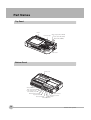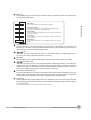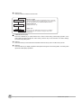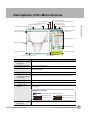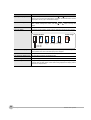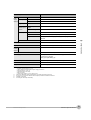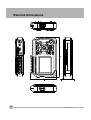
1
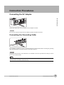
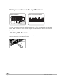
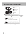
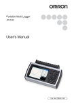
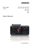
Portable Multi Logger ZR-RX20 Start Up Guide Cat. No. Z256-E1-03 Introduction This manual provides information regarding functions, performance and operating methods that are required for using the ZR-RX20. When using the ZR-RX20, be sure to observe the following: · The ZR-RX20 must be operated by personnel knowledgeable in electrical engineering. · To ensure correct use, please read this manual thoroughly to deepen your understanding of the product. · Please keep this manual in a safe place so that it can be referred to whenever necessary. Type of Manuals The manuals of the ZR-RX20 series consist of the following. Select the manual suitable for your purpose and read it before starting operation. Manual packaged in the product (brochure) Start Up Guide (this manual) Portable Multi Logger ZR-RX20 The basic information to use the ZR-RX20 series is described, such as the information for safe and correct use, confirmation of the package, procedure from connection to measurement, and the information of functions and specifications of the ZR-RX20 series. Start Up Guide Cat. No. Z256-E1-01 Manuals contained in the utility CD-ROM (pdf data) Software Manual Information for installing PC software, basic operation, explanation of screen and setting methods is described. Two PC software manuals are contained: · Special PC software "Wave Inspire RX" · Basic PC software "Smart Viewer RX20" Start Up Guide Same contents as the above referenced "Start Up Guide" packaged in the product. User's Manual · Information for safe and correct use · Before use: connection and wiring in details, language change of display, etc. · Procedure in details for setting and measurement · Specifications of the ZR-RX20 series and accessories · Other information which is required for the use of the ZR-RX20 series APPLICATION CONSIDERATIONS (Please Read) BEFORE USE 1 BASIC OPERATIONS 2 SPECIFICATIONS 3 Start Up Guide Portable Multi Logger ZR-RX20 READ AND UNDERSTAND THIS DOCUMENT Please read and understand this document before using the products. Please consult your OMRON representative if you have any questions or comments. WARRANTY OMRON’s exclusive warranty is that the products are free from defects in materials and workmanship for a period of one year (or other period if specified) from date of sale by OMRON. OMRON MAKES NO WARRANTY OR REPRESENTATION, EXPRESS OR IMPLIED, REGARDING NONINFRINGEMENT, MERCHANTABILITY, OR FITNESS FOR PARTICULAR PURPOSE OF THE PRODUCTS. ANY BUYER OR USER ACKNOWLEDGES THAT THE BUYER OR USER ALONE HAS DETERMINED THAT THE PRODUCTS WILL SUITABLY MEET THE REQUIREMENTS OF THEIR INTENDED USE. OMRON DISCLAIMS ALL OTHER WARRANTIES, EXPRESS OR IMPLIED. LIMITATIONS OF LIABILITY OMRON SHALL NOT BE RESPONSIBLE FOR SPECIAL, INDIRECT, OR CONSEQUENTIAL DAMAGES, LOSS OF PROFITS OR COMMERCIAL LOSS IN ANY WAY CONNECTED WITH THE PRODUCTS, WHETHER SUCH CLAIM IS BASED ON CONTRACT, WARRANTY, NEGLIGENCE, OR STRICT LIABILITY. In no event shall responsibility of OMRON for any act exceed the individual price of the product on which liability is asserted. IN NO EVENT SHALL OMRON BE RESPONSIBLE FOR WARRANTY, REPAIR, OR OTHER CLAIMS REGARDING THE PRODUCTS UNLESS OMRON’S ANALYSIS CONFIRMS THAT THE PRODUCTS WERE PROPERLY HANDLED, STORED, INSTALLED, AND MAINTAINED AND NOT SUBJECT TO CONTAMINATION, ABUSE, MISUSE, OR INAPPROPRIATE MODIFICATION OR REPAIR. SUITABILITY FOR USE THE PRODUCTS CONTAINED IN THIS DOCUMENT ARE NOT SAFETY RATED. THEY ARE NOT DESIGNED OR RATED FOR ENSURING SAFETY OF PERSONS, AND SHOULD NOT BE RELIED UPON AS A SAFETY COMPONENT OR PROTECTIVE DEVICE FOR SUCH PURPOSES. Please refer to separate catalogs for OMRON’s safety rated products. OMRON shall not be responsible for conformity with any standards, codes, or regulations that apply to the combination of products in the customer’s application or use of the product. At the customer’s request, OMRON will provide applicable third party certification documents identifying ratings and limitations of use that apply to the products. This information by itself is not sufficient for a complete determination of the suitability of the products in combination with the end product, machine, system, or other application or use. The following are some examples of applications for which particular attention must be given. This is not intended to be an exhaustive list of all possible uses of the products, nor is it intended to imply that the uses listed may be suitable for the products: • Outdoor use, uses involving potential chemical contamination or electrical interference, or conditions or uses not described in this document. 2 ZR-RX20 Start Up Guide • Nuclear energy control systems, combustion systems, railroad systems, aviation systems, medical equipment, amusement machines, vehicles, safety equipment, and installations subject to separate industry or government regulations. • Systems, machines, and equipment that could present a risk to life or property. Please know and observe all prohibitions of use applicable to the products. NEVER USE THE PRODUCTS FOR AN APPLICATION INVOLVING SERIOUS RISK TO LIFE OR PROPERTY WITHOUT ENSURING THAT THE SYSTEM AS A WHOLE HAS BEEN DESIGNED TO ADDRESS THE RISKS, AND THAT THE OMRON PRODUCT IS PROPERLY RATED AND INSTALLED FOR THE INTENDED USE WITHIN THE OVERALL EQUIPMENT OR SYSTEM. PERFORMANCE DATA Performance data given in this document is provided as a guide for the user in determining suitability and does not constitute a warranty. It may represent the result of OMRON’s test conditions, and the users must correlate it to actual application requirements. Actual performance is subject to the OMRON Warranty and Limitations of Liability. CHANGE IN SPECIFICATIONS Product specifications and accessories may be changed at any time based on improvements and other reasons. It is our practice to change model numbers when published ratings or features are changed, or when significant construction changes are made. However, some specifications of the product may be changed without any notice. When in doubt, special model numbers may be assigned to fix or establish key specifications for your application on your request. Please consult with your OMRON representative at any time to confirm actual specifications of purchased products. DIMENSIONS AND WEIGHTS Dimensions and weights are nominal and are not to be used for manufacturing purposes, even when tolerances are shown. ERRORS AND OMISSIONS The information in this document has been carefully checked and is believed to be accurate; however, no responsibility is assumed for clerical, typographical, or proofreading errors, or omissions. PROGRAMMABLE PRODUCTS OMRON shall not be responsible for the user’s programming of a programmable product, or any consequence thereof. COPYRIGHT AND COPY PERMISSION This document shall not be copied for sales or promotions without permission. This document is protected by copyright and is intended solely for use in conjunction with the product. Please notify us before copying or reproducing this document in any manner, for any other purpose. If copying or transmitting this document to another, please copy or transmit it in its entirety. ZR-RX20 Start Up Guide 3 Notice on European EMC Directive (2004/108/EC) This product meets CISPR11 class A. The intended use of this product is in an industrial environment only. Traceability Information zRepresentative in EU Omron Europe B.V. Wegalaan 67-69 2132 JD Hoofddorp, The Netherlands zManufacturer Omron Corporation, Sensing Devices & Components Div. H.Q., Application Sensors Division Shiokoji Horikawa, Shimogyo-ku, Kyoto 600-8530 JAPAN 4 ZR-RX20 Start Up Guide Meanings of Signal Words The following signal words are used in this manual. Indicates a potentially hazardous situation which, if not avoided, will result in minor or moderate injury, or may result in serious injury or death. Additionally there may be significant property damage. Indicates a potentially hazardous situation which, if not avoided, may result in minor or moderate injury or in property damage. Meanings of Alert Symbols The following alert symbols are used in this manual. Indicates the possibility of explosion under specific conditions. Indicates the possibility of electric shock under specific conditions. Indicates prohibition when there is a risk of minor injury from electrical shock or other source if the product is disassembled. Indicates general prohibitions for which there is no specific symbol. ZR-RX20 Start Up Guide 5 Alert Statements in this Manual The following alert statements apply to the products in this manual. Each alert statement also appears at the locations needed in this manual to attract your attention. This product cannot be used for directly or indirectly detecting human bodies to ensure safety. Do not use this product as a human body protection device. Serious hazard may occur in rare occasions due to ignition, rupture or combustion of the lithium battery contained in this product. Never disassemble, deform under pressure, heat or incinerate this product. Injuries from electric shock may occur in rare occasions as the result of disassembly. Never disassemble, deform under pressure or incinerate the main unit. Hazard may occur from serious fire or electric shock. Do not connect voltages exceeding the rated voltage to the signal input terminals. Fire or hazard may occur in rare occasions from ignition, rupture or combustion. Do not use battery packs other than ZR-XRB1. 6 ZR-RX20 Start Up Guide Precautions for Safe Use Be sure to observe the following items as they are very important to ensure safety. 1.Installation environment • • • • Do not store or use in locations where the temperature exceeds the rated range. Do not use in locations where the relative humidity exceeds the 30 to 80 %RH range. Do not use in locations subject to steam. Do not use in flammable or explodable gas environment. 2.Power supply and wiring • • • • • • • • Do not connect voltages exceeding the rated voltage to signal cables. Be sure to check the polarity of the signals when connecting the signal cables. When using the battery pack, be sure to read the cautions on the battery pack carefully for correct usage. Be sure to use only the specified battery pack. Be sure to use only the AC cable and the AC adapter provided as standard accessories. Do not connect power supplies exceeding the rated voltage to the AC adapter. Be sure to turn off the power supply when connecting to the input terminals. Do not touch the input terminals during measurement. 3.Others • Dispose of this product as industrial waste. • If there are any troubles, stop usage immediately, turn off the power supply and contact OMRON branch or sales office. ZR-RX20 Start Up Guide 7 Precautions for Correct Use Please observe the following precautions to prevent inoperability, misoperation of the product or negative effects on the performance and the device. 1.Installation Location Do not install this product in the following locations. • • • • • • • • Locations where the temperature exceeds the rated range Locations where severe changes in temperature occur (where condensation occurs) Locations subject to corrosive or flammable gases Locations subject to dust, salt or iron powder Locations subject to direct shock or vibration Locations subject to direct sunlight or near heating devices Locations where water, oil or chemical products may be splashed Locations subject to strong magnetic fields or strong electric fields 2.Power supply, connecting and wiring • The cables should be wired apart from high-tension or power lines. Malfunction or damage may occur due to induction. • After wiring, check the adequacy of power supply voltage, miswiring such as overvoltage/load shortcircuiting and adequacy of load current before turning on the power supply. Malfunction may occur due to miswiring and such. • Always turn off the power supply when attaching or removing peripheral devices. Attaching or removing of peripheral devices with the power supply on can cause malfunction or data corruption. 3.Installation • Do not cover the vent hole when using this product. Leave at least 30cm of installation space around this product. The generated heat may cause malfunction or damage. • When measuring temperature, install the product so that the input terminals are not subject to severe changes in temperature by wind or sunlight. It may cause calculation errors. • Do not install this product in a slanted or vertical position. • Connect the GND terminal for safe measurement. This product must also be grounded when sharing a common ground level with other devices. 4.Warm up • For stable measurement, wait at least 30 minutes after turning on the power supply before using. 5.Handling • Be sure to take backups of captured data in your PC. The captured content may be altered or lost due to misuse or malfunctions during usage. • Do not drop or apply strong impact or force to the product. It may cause malfunction of the monitor or the main unit. 6.Maintenance • Do not use thinner, benzine, acetone or kerosene to clean this product. • Calibration should be performed periodically to maintain measurement accuracy. 8 ZR-RX20 Start Up Guide Checking the Accessories Item Remarks Quantity Main unit ZR-RX20 1 Start Up Guide This manual 1 Utility disk • • • • • • 1 AC cable/AC adapter 100 to 240 VAC, 50/60 Hz ZR-RX20 Start Up Guide Specal PC software “Wave Inspire RX“ (tryout) Basic PC software “Smart Viewer RX20” Start Up Guide PDF files User's Manual PDF files “Wave Inspire RX“ Software Manual PDF files “Smart Viewer RX20” Software Manual PDF files 1 9 Editor's Note Meaning of Symbols Menu items that are displayed on the ZR-RX20's LCD screen, and windows, dialog boxes and other GUI elements displayed on the PC are indicated enclosed by brackets "[ ]". Visual Aids Important Note Indicates points that are important to achieve the full product performance, such as operational precautions. Indicates application procedures. Indicates pages where related information can be found. 10 ZR-RX20 Start Up Guide CONTENTS 1.BEFORE USE Part Names. . . . . . . . . . . . . . . . . . . . . . . . . . . . . . . . . . . . . . . . . . . . . . . . . . 14 Connection Procedures . . . . . . . . . . . . . . . . . . . . . . . . . . . . . . . . . . . . . . . 15 Connecting the AC Adapter . . . . . . . . . . . . . . . . . . . . . . . . . . . . . . . . . . . . . . . . . 15 Connecting the Grounding Cable. . . . . . . . . . . . . . . . . . . . . . . . . . . . . . . . . . . . . 15 Making Connections to the Input Terminals. . . . . . . . . . . . . . . . . . . . . . . . . . . . . 16 Attaching USB Memory . . . . . . . . . . . . . . . . . . . . . . . . . . . . . . . . . . . . . . . . . . . . 16 Setting the Date and Time . . . . . . . . . . . . . . . . . . . . . . . . . . . . . . . . . . . . . 17 Descriptions of the Control Panel Keys . . . . . . . . . . . . . . . . . . . . . . . . . . 18 Descriptions of the Menu Screens . . . . . . . . . . . . . . . . . . . . . . . . . . . . . . 21 2.BASIC OPERATIONS CONTENTS Measurement Procedure . . . . . . . . . . . . . . . . . . . . . . . . . . . . . . . . . . . . . . 24 1. Preparations: Preparations for Data Capture . . . . . . . . . . . . . . . . . . . . 25 2. Setup: Setting the Temperature Measurement. . . . . . . . . . . . . . . . . . . 26 3. Data Capture: Measuring the Temperature. . . . . . . . . . . . . . . . . . . . . . 30 4. Data Replay: Replaying Captured Data. . . . . . . . . . . . . . . . . . . . . . . . . 32 Convenient Functions. . . . . . . . . . . . . . . . . . . . . . . . . . . . . . . . . . . . . . . . . 33 Trigger Functions . . . . . . . . . . . . . . . . . . . . . . . . . . . . . . . . . . . . . . . . . . . . . . . . . 33 Span, Position and Trace Functions . . . . . . . . . . . . . . . . . . . . . . . . . . . . . . . . . . 33 Quick Settings . . . . . . . . . . . . . . . . . . . . . . . . . . . . . . . . . . . . . . . . . . . . . . . . . . . 33 3.SPECIFICATIONS Standard Specifications . . . . . . . . . . . . . . . . . . . . . . . . . . . . . . . . . . . . . . . 36 External Dimensions. . . . . . . . . . . . . . . . . . . . . . . . . . . . . . . . . . . . . . . . . . 38 Revision History . . . . . . . . . . . . . . . . . . . . . . . . . . . . . . . . . . . . . . . . . . . . . 40 ZR-RX20 Start Up Guide 11 1 BEFORE USE BEFORE USE Part Names 14 Connection Procedures 15 Setting the Date and Time 17 Descriptions of the Control Panel Keys 18 Descriptions of the Menu Screens 21 Part Names Top Panel Monitor Battery charging LED (CHARGE) Control panel keys Data capture LED (START) Power LED (POWER) Power switch Bottom Panel Battery cover Analog input terminals Alarm output terminal Power output connector for the humidity sensor External trigger terminal AC adapter connector Logic input terminal USB interface terminal Pulse input terminal GND terminal USB device terminal 14 Part Names ZR-RX20 Start Up Guide Connection Procedures Connecting the AC Adapter 1 BEFORE USE Connect the output side of the AC adapter to the AC adapter connector. Important Be sure to use only the AC cable and the AC adapter provided as standard accessories. Connecting the Grounding Cable Grounding cable Use a flatblade screwdriver to push in the button above the ground terminal while connecting the grounding cable to the ZR-RX20. Connect the other end of the cable to ground. Important Connect the GND terminal for safe measurement. The ZR-RX20 must also be grounded when sharing a common ground level with other devices. Note The grounding cable is not provided as a standard accessory and must be prepared separately. [Recommended Cord Diameter: AWG18/UL1007] ZR-RX20 Start Up Guide Connection Procedures 15 Making Connections to the Input Terminals Analog input terminals CH1 CH2 CH3 CH4 CH5 CH6 CH7 CH8 CH9 CH10 Signal source Voltage Thermocouple orming current measurement Pulse, Logic, External Trigger and Alarm Terminals When the current is 4 to 20 mA, attach a 250Ω resistor and perform measurement in the 1 to 5 V range Refer to the channel numbers in the above figure to connect analog input terminals to the desired terminal. The pulse, logic, external trigger and alarm terminals all have the same configuration as that of the GND terminal. Make connections to these terminals using the procedure described earlier for connecting the grounding cable. Connect each terminal in accordance with the name inscribed above each terminal. Attaching USB Memory You're able to store measured data directly to the USB memory device. Attach the USB memory to the USB device terminal. USB memory device 16 Connection Procedures ZR-RX20 Start Up Guide Setting the Date and Time The ZR-RX20 includes a rechargeable internal battery for backup. If you are using the ZR-RX20 for the first time, charge the internal rechargeable battery and then make the date and time settings. 1 Note BEFORE USE If the ZR-RX20 is not used for a period of approximately three months, the internal rechargeable battery may be discharged and the date and time may revert to the initial settings. If this happens, recharge the battery before using the ZR-RX20. How to Recharge the Rechargeable Battery Using the AC adapter provided, connect the ZR-RX20 to a mains power outlet, turn on the power switch, and then leave the ZR-RX20 connected for at least 24 hours. How to Set the Date and Time Press the MENU key, display the [OTHR] screen, and then set the date and time at the Date/Time Settings sub-menu. "Setting the Date and Time" section in the User's manual ZR-RX20 Start Up Guide Setting the Date and Time 17 Descriptions of the Control Panel Keys 1 2 1 SPAN/POSITION/TRACE 2 TIME/DIV 3 4 3 MENU 4 QUIT (LOCAL) 5 5 6 keys (up, down, left, right) 6 ENTER 7 7 7 keys (KEY LOCK) 8 START/STOP (USB DRIVE MODE) 9 REVIEW 12 11 10 DISPLAY 10 8 13 9 1 11 CURSOR (ALM CLR) 12 FILE 13 NAVI SPAN/POSITION/TRACE key This key enables SPAN, POSITION, and TRACE settings to be made independently for each channel. Each time this key is pressed, the mode displayed in the waveform operation display area changes in the sequence shown below. Use the and keys to select the channel, and the and keys to change the setting values. MONITOR SPAN POSITION TRACE Displays digital values (default). Used to make span settings (change the waveform amplitude). Used to make position settings (adjust the upper and lower values of the waveform). Used to make trace settings (set the waveform display to On or Off). Note: If the QUIT key is pressed when the ZR-RX20 is in the SPAN, POSITION, or TRACE mode, the display returns to MONITOR mode. 2 18 TIME/DIV key Press the TIME/DIV key to change the time axis display range on the waveform screen. Descriptions of the Control Panel Keys ZR-RX20 Start Up Guide 3 MENU key Press the MENU key to open a setup menu. Each time this key is pressed, the setup screen tabs change in the sequence shown below. AMP · AMP Settings Used to make the input, range, filter and other settings. 1 TRIG USER OTHR · Data Capture Settings Used to make settings such as the sampling interval, data capture destination, and calculations during data capture. BEFORE USE DATA · Trigger Settings Used to specify the data capture start and stop conditions, and the alarm generation conditions. · User Settings Used to set the names of the users of this device, and to change from one user to another. · Other Settings Used to make settings such as screen brightness, temperature unit, and so forth. 4 QUIT (LOCAL) key Press the QUIT key to cancel the settings and return them to their default status. If the device is in the Remote (Key Lock) status, namely the external operating status via the USB interface, press this key to return the device to the normal operating status (Local). 5 keys These keys are used to select menu setup items, to make span settings in the digital display area, to move the cursors during a data replay operation, and so forth. 6 ENTER key Press the ENTER key to enter the settings made in the setup menus, and to confirm your settings. 7 keys (KEY LOCK) These keys are used to move the cursor at high speed during a data replay operation, and to change the operation mode in the file settings box. Hold down both keys simultaneously for at least two seconds to enable key lock status. To cancel key lock status, press them again for at least two seconds. The key lock status can be confirmed by the status of the key lock lamp on the monitor. 8 START/STOP (USB DRIVE) key Press the START/STOP key to perform a data capture start operation while the ZR-RX20 is in the Free Running status, and a data capture stop operation when data capture has ended. If this key is held down while the power to the ZR-RX20 is turned on, the ZR-RX20 goes into USB Drive Mode. 9 REVIEW key Press the REVIEW key to replay captured data. If the ZR-RX20 is in the Free Running status, data files that have already been captured are replayed. If the ZR-RX20 is still capturing data, the data is replayed in a 2-screen format. Note: A data replay operation will not be performed if data has not been captured. ZR-RX20 Start Up Guide Descriptions of the Control Panel Keys 19 10 DISPLAY key This key is used to switch the window mode. Waveform + Digital Expanded Waveform Digital + Calc. 20 · Waveform + Digital This is the default screen when the ZR-RX20 is turned on, and both waveforms and digital values are displayed. The screen settings can also be changed by using the SPAN/POSITION/TRACE key. · Expanded Waveform Displays waveforms only. · Digital + Calc. Displays large-size digital values and two types of calculation processing results. The calculation settings are made in the [DATA] menu. 11 CURSOR (ALM CLR) key Press the CURSOR key to switch between the A and B cursors during a data replay operation. If the Alarm setting has been specified as "Alarm Hold", press this key to clear the alarm. The alarm settings are made in the [TRIG] menu. 12 FILE key Press the FILE key to save data to the ZR-RX20's internal memory and to a USB memory device. 13 NAVI key Press the NAVI key to display operational descriptions during the Free Running status, and during data capture and data replay operations. Descriptions of the Control Panel Keys ZR-RX20 Start Up Guide Descriptions of the Menu Screens (5) USB device lamp (internal memory/USB access lamp) (4) Logic display area (3) Alarm display area (6) Key lock lamp (2) Time/DIV display area (7) Remote lamp 1 (1) Simplified message display area (8) AC/Battery status indicator BEFORE USE (18) Data capture bar (17) Scale upper limit (9) Waveform operation display area (10) Digital display area (16) Waveform display area (11) Quick settings (12) User information (15) Scale lower limit (14) File name display area (13) Pen display Item Description (1) Simplified message display area Displays the operating status. (2) Time/DIV display area Displays the current time scale. (3) Alarm display area Displays the status of the alarm output terminal. (Red = alarm generated, white = alarm not generated) (4) Logic display area Displays the status of the logic signal. (Blue = Hi, white = Lo) (5) USB device lamp (internal memory/USB access lamp) Turns green when a USB memory device has been inserted. When the ZR-RX20's internal memory or USB memory device is being accessed, this lamp turns red. (6) Key lock lamp Displays the key lock status. (Yellow = keys locked, white = not locked) (7) Remote lamp Displays the remote status. (Yellow = Remote status, white = Local status) (8) AC/Battery status indicator Displays the following icons to indicate the operating status of the AC power supply and the battery. AC/Battery Indicator When the AC power supply is being used (9) Waveform operation display area ZR-RX20 Start Up Guide Battery power: Full Battery power: Medium Battery power: Low Battery power: Very low Displays the mode selected by the SPAN/POSITION/TRACE key. Descriptions of the Menu Screens 21 Item Description (10) Digital display area Displays the input values for each channel. The and keys can be used to select the active channel (enlarged display). Moreover, the selected active channel is displayed at the very top of the waveform display. (11) Quick settings Displays items that can be easily set. The make a Quick settings item active, and the values. (12) User information Displays the user information for the currently selected user. (13) Pen display Displays the signal positions, trigger positions, and alarm ranges for each channel. and and keys can be used to keys to change the Trigger position Rising trigger Alarm range Falling trigger Within Outside the range the range Stop side Start side (14) File name display area Displays the data capture file name during the data capture operation. During a data replay operation, the name of the data replay file is displayed. (15) Scale lower limit Displays the lower limit of the scale of the currently active channel. (16) Waveform display area The input signal waveforms are displayed here. 22 (17) Scale upper limit Displays the upper limit of the scale of the currently active channel. (18) Data capture bar During a data capture operation, this bar displays the remaining memory capacity of the device used for data capture. When data is being replayed, the display position information is displayed here. Descriptions of the Menu Screens ZR-RX20 Start Up Guide BASIC OPERATIONS 2 24 1. Preparations: Preparations for Data Capture 25 2. Setup: Setting the Temperature Measurement 26 3. Data Capture: Measuring the Temperature 30 4. Data Replay: Replaying Captured Data 32 Convenient Functions 33 BASIC OPERATIONS Measurement Procedure Measurement Procedure In this section we will provide a simple explanation of the data capture procedure: Preparations J Setup J Data Capture J Data Replay. T thermocouples will be used here to perform temperature measurement. 24 Purpose of data capture To measure the temperature of the target objects Measurement points 2 locations Sampling interval 1 second Data save destination USB memory device Important point We want to check captured data even during a data capture operation. Items that must be supplied Note: If you do not have a USB memory device, capture data to the ZR-RX20's internal memory instead. T thermocouples, USB memory device Measurement Procedure ZR-RX20 Start Up Guide 1. Preparations: Preparations for Data Capture Connect the thermocouple to measurement object 1 and the CH 1 terminal. 2 Connect the thermocouple to measurement object 2 and the CH 2 terminal. 3 Connect the AC adapter. 4 Insert the USB memory device. 5 Turn on the power supply. 2 1 2 CH 1 T thermocouple BASIC OPERATIONS 4 3 1 CH 2 T thermocouple 5 Measurement object 1 ZR-RX20 Start Up Guide Measurement object 2 1. Preparations: Preparations for Data Capture 25 2. Setup: Setting the Temperature Measurement Make the settings required for data capture. Here we will make only those settings that are absolutely necessary. The other settings will be left as the default settings (the settings made prior to shipment from the factory). Note Basic Setup Menu Operation The keys used on the menu screens are the keys, the ENTER key, and the QUIT key. The current cursor position is displayed in green. Use the keys to move the cursor. If you press the ENTER key at the cursor position, a selection menu or a box for inputting numeric values and so forth is displayed. If you press the QUIT key, the screen closes and the settings are canceled. Examples of selection menu operations (AMP screen) 1. Use the keys to move the cursor to the Input parameter opposite CH 1 and then press the ENTER key. 2. A selection menu is displayed when the ENTER key is pressed. Use the and keys to select "TEMP." 3. Press the ENTER key to confirm your selection. Note: For voltage measurement, select "DC". 1 1 2 3 2 Press the MENU key to display the setup menu screen. Select [TEMP.] for the Input parameter for CH 1 and CH 2. (a) Move the cursor to the [Input] parameter opposite CH 1 and select [TEMP.] (b) 3 Make the same setting for CH 2. Select [TC-T] for the Range parameter for CH 1 and CH 2. (a) Move the cursor to the [Range] parameter opposite CH 1 and select [TC-T]. (b) Make the same setting for CH2. 26 2. Setup: Setting the Temperature Measurement ZR-RX20 Start Up Guide 4 Select "Off" for all the other channels. (a) Using the procedure described above, select [off] for CH 3 to CH 10. 5 6 5 Press the MENU key and open the [DATA] menu. 6 Set the sampling interval to "1s". Move the cursor to [Sampling] and then select [1s]. 2 7 – –(a)(b) (a)(b) (a) (b) BASIC OPERATIONS 7 Specify the Capture Destination file name. Here we will create a folder named [TEST] in the USB memory device, and then make the settings required to enable data to be captured to the TEST folder. (a) Move the cursor to the File Name parameter and then press the ENTER key. (b) With the cursor on the [<MEM>] item in the following screen, press the ENTER key. 7 – –(c)(d)(e) (c)(d)(e) (c) (d)(e) (c) The file settings box shown in the following screen opens. This box is used to specify file names for the ZR-RX20's internal memory and for the USB memory device. Use the high-speed and change the operation mode. keys to In the Select file/folder screen displayed, • Use the and keys to move the cursor up or down. • Use the and keys to move to the Folder level. • Use the ENTER key to confirm your setting. • Use the QUIT key to cancel your setting. (d) Move the cursor to [<USB1>] and then press the key. (e) Press the key to move the cursor to [Create new folder] and then press the ENTER key. ZR-RX20 Start Up Guide 2. Setup: Setting the Temperature Measurement 27 (f) A text input box is displayed. Let's create a folder named "TEST". 7 – –(f)(g) (f)(g) (f) (g) Text input box Select the text type; delete; insert; confirm Select the text · Use the and keys to move the cursor up or down. · Use the and keys to move the cursor to the right or left. · Use the ENTER key to input the name. (g) Input "TEST", move the cursor to "OK", and then press the ENTER key to confirm your setting. 7 – –(h) (h) (h) As shown in the following screen, a folder named "<TEST>" has been created. Press the key to move the cursor to [Select file/ folder] and use the keys to select the "<TEST>" folder, and then press the ENTER key. Use the high speed and change the operation mode. keys to In the Select file/folder screen displayed, · Use the and keys to move the cursor up or down. · Use the and keys to move to the Folder level. · Use the ENTER key to confirm your setting. · Use the QUIT key to cancel your setting (i) 7 – –(i) (i) 28 2. Setup: Setting the Temperature Measurement Check that "<TEST>" appears opposite "Folder", move the cursor to the [OK] button, and then press the ENTER key. ZR-RX20 Start Up Guide (j) In the screen displayed below, we can check the capture destination, the amount of data that can be captured, and the allowable data capture time. 2 BASIC OPERATIONS This completes all the settings required for data capture. ZR-RX20 Start Up Guide 2. Setup: Setting the Temperature Measurement 29 3. Data Capture: Measuring the Temperature During the data capture operation, you can replay some data that was captured previously to check the data. 1 Starting data capture (a) Press the START/STOP key. (b) A confirmation message is displayed. 1 –(c) (c) Start Data Capture ? [ENTER] Yes [QUIT] No 1 –(a) (a) (c) Press the ENTER key to start data capture. 2 Screen status during data capture Once data capture has started, the elapsed time and the allowable data capture time are counted. Message displayed during data capture Elapsed time 3 3 Allowable data capture time Replaying data being captured Data that was captured in the past can be replayed while new data is being captured to the ZR-RX20. In addition, the past data can be compared with the current input waveform in a 2-screen format. (a) Press the REVIEW key to display the data in a 2screen format. Display position Cursor A Cursor B Past data <Main operations> New data Selected cursor • Cursor A temperature value • Cursor B temperature value • Difference between the A and B values • Sampling interval • Selected cursor time • Time difference between A and B • Use the and keys to move the cursor • Use the and keys to move the cursor at high speed • Use the CURSOR key to change your cursor selection (ABA) (b) Move the cursor as desired to check the captured waveforms, date/time, and so forth. 30 3. Data Capture: Measuring the Temperature ZR-RX20 Start Up Guide 4 Stopping data capture Press the START/STOP key to end the data capture operation. 4 -(c) (c) (a) Press the START/STOP key. Stop Data Capture ? 4 -(a) (a) [ENTER] Yes [QUIT] No (b) A confirmation message is displayed. Press the ENTER key. 2 BASIC OPERATIONS (c) Data capture ends, and the ZR-RX20 goes into the Free Running status. This completes the data capture operation. ZR-RX20 Start Up Guide 3. Data Capture: Measuring the Temperature 31 4. Data Replay: Replaying Captured Data Now that data capture has been completed, let's replay some of that captured data. The data has been captured to the <TEST> folder that was created in the USB memory device in Step 7 of Section 2, "Setup". The file name is appended automatically, and therefore the name of the file that was created is "Year/month/date-time_UG.gbd". The year/month/date and time are those that were in effect when data capture started. 1 Selecting a file to replay (a) Press the REVIEW key. 1 –(b) (b) (b) Since the file you want to replay has the file name that was appended automatically when the data was captured, move the cursor to the [OK] button and then press the ENTER key. 1 –(a) (a) (c) The Replay screen opens. (d) Move the cursor as desired to check the captured waveforms, date/time, and so forth. The SPAN/ POSITION/TRACE key can also be used in the Replay screen to change the span, position, trace, zone and other displayed settings. (e) Press the QUIT key to end the data replay operation. A confirmation message is displayed. Press the ENTER key. 1 –(e) End data Replay ? [ENTER] Yes [QUIT] No (f) Data replay ends, and the ZR-RX20 goes into the Free Running status. This completes our simple explanation of how to use the basic ZR-RX20 functions. 32 4. Data Replay: Replaying Captured Data ZR-RX20 Start Up Guide Convenient Functions Trigger Functions Trigger functions can be used to control the timing of the start of a data capture operation, and the timing of the end of a data capture operation. Note 2 For example... You can use trigger functions to perform operations such as the following: • Start data capture when the voltage exceeds 1 V • Stop data capture at 1:00 pm • Perform control via external input BASIC OPERATIONS Span, Position and Trace Functions These functions enable you to make adjustments in order to view individual channels more easily, and to delete waveforms that you do not need to view. Note The span, position and trace operations can be performed while the ZR-RX20 is in the Free Running status, while it capturing data, and while it is replaying data. The changes made are applied to the displayed data only, and so the original data is not affected in any way. Quick Settings The Quick settings function can be used to change the settings of the two items displayed respectively in the Free Running status and during data replay. Free Running status:Sampling interval, Zone divisions During data capture: Zone divisions only During data replay: Search, Zone divisions ZR-RX20 Start Up Guide Convenient Functions 33 SPECIFICATIONS 3 36 External Dimensions 38 SPECIFICATIONS Standard Specifications Standard Specifications Main unit specifications ZR-RX20A Analog Input method input Number of channels section A/D resolution Photo MOS relay scanning system; all channels isolated 10 ch 16-bit Measurement Voltage ranges Temperature Humidity (*1) Measurement Voltage accuracy Thermo(*2) (*3) couple Thermocouples: K, J, E, T, R, S, B, N, W (WRe5-26) 0 to 100 % (Voltage 0 to 1 V scaling conversion) ±0.1 % of F.S. Type Measurement Temperature Range (° C) Measurement Accuracy R/S 0 ≤TS ≤100 ±5.2 ° C 100 < TS ≤300 ±3.0 ° C R: 300 < TS ≤1600 ° C ±(0.05 % of rdg +2.0 ° C) S: 300 < TS ≤1760 ° C ±(0.05 % of rdg +2.0 ° C) 400 ≤TS ≤600 ±3.5 ° C 600 < TS ≤1820 ° C ±(0.05 % of rdg +2.0 ° C) –200 ≤TS ≤–100 ±(0.05 % of rdg +2.0 ° C) –100 < TS ≤1370 ° C ±(0.05 % of rdg +1.0 ° C) –200 ≤TS ≤–100 ±(0.05 % of rdg +2.0 ° C) –100 < TS ≤800 ° C ±(0.05 % of rdg +1.0 ° C) –200 ≤TS ≤–100 ±(0.1 % of rdg +1.5 ° C) –100 < TS ≤400 ° C ±(0.1 % of rdg +0.5 ° C) –200 ≤TS ≤–100 ±2.7 ° C –100 < TS ≤100 ±1.7 ° C 100 < TS ≤1100 ° C ±(0.05 % of rdg +1.0 ° C) N 0 ≤TS ≤1300 ° C ±(0.1 % of rdg +1.0 ° C) W 0 ≤TS ≤2315 ° C ±(0.1 % of rdg +1.5 ° C) B K E T J Reference contact compensation accuracy 36 20, 50, 100, 200, 500 mV; 1, 2, 5, 10, 20, 50 V; 1-5 V F.S. ±0.5 ° C (23 ° C ±2 ° C, when the input terminal temperature is balanced) Maximum input voltage 60 Vp-p Reference contact compensation Internal/External switching Input impedance 1 MΩ ±5 % Allowable signal source resistance 300 Ω or less Temperature coefficient Gain: 0.01 % of F.S./° C Withstand voltage 350 Vp-p (between each input channel/main unit chassis; between each chs) 1 minute Insulation resistance Between main unit chassis: At least 50 MΩ (at 500 VDC) Standard Specifications ZR-RX20 Start Up Guide ZR-RX20A Main unit specifications External Logic input Input/ Pulse input Output Sections Trigger input Number of channels 1 ch Number of channels 1 ch Modes Revolutions mode, Counts mode, Inst. Mode switch method Number of channels 1 ch Specifications Maximum input of each input voltage section Threshold voltage 24 V Alarm output Number of channels 1 ch Output format Open collector output (100 kΩ pull-up resistance) Output conditions Level judgment, window judgment, logic pattern judgment, pulse judgment USB 1.1 3 PC I/F Approx. 2.5 V 100, 200, 500 ms; 1, 2, 5, 10, 20, 30 s; 1, 2, 5, 10, 20, 30 min; 1 h Display 3.5-inch TFT color LCD (320 x 240 dots) Internal Internal memory memory devices Approx. 3.5 MB Operating environment 0 to 40 ° C, 30 to 80 % RH (15 to 40 ° C when the battery is used) Power supply AC adapter: 100 to 240 VAC/50 to 60 Hz (*4) DC input: 8.5 to 24 VDC Battery pack (ZR-XRB1) (*5) Power consumption 28 VA or less (when the AC adapter is used) External dimensions 194 x 122 x 41 mm Weight Approx. 480 g (*6) *1 *2 *3 *4 *5 *6 SPECIFICATIONS Sampling interval When ZR-XRH1 (Option) is used Features under the following measurement parameters • Operating environment 23 ° C ±3 ° C • Left for at least 30 minutes after the power supply is turned on • Sampling interval 1 s (10 ch) • Filter ON (Average: 10 times) • GND connection • Thermocouple used is T: 0.32 ∅, other: 0.65 ∅ Refer to the ZR-XRH1 (Option) specifications for humidity measurement accuracy. Be sure to use only the AC cable and the AC adapter provided as standard accessories. ZR-XRB1 is an option Excluding the AC adapter and battery ZR-RX20 Start Up Guide Standard Specifications 37 External Dimensions (Unit: mm) 38 External Dimensions ZR-RX20 Start Up Guide Revision History A manual revision code appears as a suffix to the catalog number at the bottom of the front and back covers of this manual. Cat. No. Z256-E1-03 Revision code 40 Revision code Date 01 April 2007 Revised contents Original production 02 August 2007 Minor corrections 03 October 2007 Notice on EMC Directive added and minor corrections. Revision History ZR-RX20 Start Up Guide OMRON Corporation Industrial Automation Company Application Sensors Division Sensing Devices and Components Division H.Q. Shiokoji Horikawa, Shimogyo-ku, Kyoto, 600-8530 Japan Tel: (81)75-344-7068/Fax: (81)75-344-7107 Regional Headquarters OMRON EUROPE B.V. Sensor Business Unit, Carl-Benz-Str. 4, D-71154 Nufringen, Germany Tel: (49)7032-811-0/Fax: (49)7032-811-199 OMRON ELECTRONICS LLC One Commerce Drive Schaumburg IL 60173-5302 U.S.A. Tel: (1) 847-843-7900/Fax: (1) 847-843-7787 OMRON ASIA PACIFIC PTE. LTD. No. 438A Alexandra Road # 05-05/08 (Lobby 2), Alexandra Technopark, Singapore 119967 Tel: (65) 6835-3011/Fax: (65) 6835-2711 OMRON (CHINA) CO., LTD. Room 2211, Bank of China Tower, 200 Yin Cheng Zhong Road, Pu Dong New Area, Shanghai, 200120, China Tel: (86)10-8391-3005/Fax: (86)10-8391-3688 Authorized Distributor: Cat.No.Z256-E1-03 © OMRON Corporation 2007 All Rights Reserved. Note: Specifications subject to change without notice. Printed in Japan. 1007-0.1M (0407)