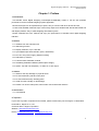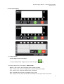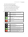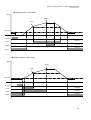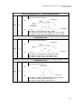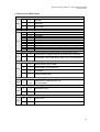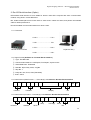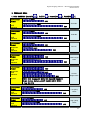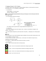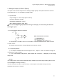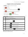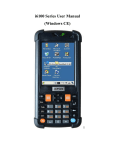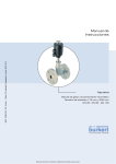
1
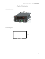
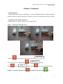
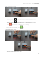
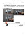
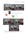
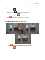
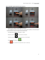
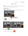
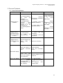
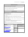
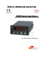
Digital Weighing Indicator
MI-800 Series User Manual
For MI-810 / MI-830 / MI-850 model
Digital Weighing Indicator – MI-810/830/850 Model
Din Size Series
Contents
Chapter 1. Preface
..
3 page
Chapter 2. Specification
..
4 page
Chapter 3. Installation
..
8 page
Chapter 4. Calibration
..
9 page
Chapter 5. Set-Up
..
19 page
Chapter 6. F-Function
..
22 page
Chapter 7. Interface
..
34 page
Chapter 8. Error and Treatment
..
42 page
Warrantee
..
45 page
2
Digital Weighing Indicator – MI-810/830/850 Model
Din Size Series
Chapter 1. Preface
1. Introduction
This MI-800 series Digital Weighing Indicator(MI-810/830/850) model is 1/8 din size powerful
performance for the industrial weighing system application.
RS-232 serial port can be expended up to 4pots, easy to connect with other devices and PC.
In case of MI-830/850 model has 3pcs control relay output as a standard and also MI-850 model has
sub-display window, easy to make weighing automation system.
Please estimated this user manual and enjoy the performance of MI-800 series digital weighing
Indicator.
2. Feature
2-1. Isolation from the external noise
2-2. Watch-dog function
2-3. Display resolution, up to 1/30,000
2-4. 2pcs Digital input terminal built in (Zero, Tare/Reset)
2-5. DC 12V~24V power supply. (Without Polarity)
2-6. Data back-up function
2-7. Full Automatic Calibration method
2-8. Simulating Calibration Method (without Span weight)
2-9. Option : Rs-485 / Rs-232(extra) / 4~20mA or 0~10V output
3. Caution
3-1. Weak for the drop damage or physical shock.
3-2. Do not install heavy electric noise place.
3-3. Do not install the heavy vibrating place.
3-4. Avoid from the humidity or rain damage.
3-5. Please Turn off the main power, when make connect with other devices.
4. Accessories
4-1. User Manual
5. Inquiries
If you have any kinds of inquiries for this model, please contact with your local agent or Head Office.
Head Office : Migun ST co.,Ltd.
Overseas Office : Migun Corporation.
Website : http://www.miguncorp.co.kr
Email : [email protected] / [email protected]
3
Digital Weighing Indicator – MI-810/830/850 Model
Din Size Series
Chapter 2. Specification
1. Analogue Input and A/D Conversion
0.3㎶ / Digit
DC 10V ( - 5V ~ + 5V )
Max.32mV
[Zero] ±10PPM/℃ / [Span] ±10PPM/℃
±0.6㎶ P.P
Over 10㏁
Sigma-Delta
520,000 Count(19bit)
Max. 200times / Sec
0.01% FS
1/30,000
Input Sensitivity
Load Cell Excitation
Max. Signal Input Voltage
Temperature Coefficient
Input Noise
Input Impedance
A/D Conversion Method
A/D Resolution(Internal)
A/D Sampling Rate
Non-Linearity
Display Resolution(External)
2. Digital Part
Display
Parts
Specification
7Segments, 5 Digit RED FND Display
Size :12.7mm(H)×7.3mm(W)
Main Display
Display
Min. Division
Max. display value
Under Zero value
Sub-Display (Only MI-850)
Status
lamp
Key
MI-810 model
Zero, Stable, TARE, AUTO,
PRINT, Hold, RTxD
MI-830 / 850 model
Zero, Stable, Low, High,
END, Hold, RTxD
Function keys
×1, ×2, ×5, ×10, ×20, ×50
+99,950
"-" (Minus display)
7Segments, 5 Digit RED FND Display
Size :8.0mm(H)×4.0mm(W)
Green LED Display(3Ø)
Zero / F / Set / Enter (4pcs function keys)
3. General Part
Power Supply
Operating Temperature Range
Operating Humidity Range
External Dimension
Net Weight(kg)
Gross Weight(kg)
DC 12~24V / About 200~300mA
-5℃ ~ 40℃
Under 85% Rh (non-condensing)
100mm(W)x52mm(H)x125mm(L)
About 450g
About 600g
4. Option
Option No.1
Option No.2
Option No.5
Option No.6
RS-422
RS-232 (Standard Installation)
4~20mA (Analogue Output)
0~10V (Analogue Output)
4
Digital Weighing Indicator – MI-810/830/850 Model
Din Size Series
5. Front Panel Display
5-1. Weight Display
- Current Weight value will be Display
- In case of MI-830 model, display set value, whenever press
key.
5-2. Status Lamp (From Left to Right) – MI 810 model
- Steady : Lamp is “ON”, when the weight value is stable condition.
- Zero : Lamp is “ON”, when the weight value is Zero(including Tare weight)
- Tare : Lamp is “ON”, when the TARE function is activated
- Auto : Automatic Print Function is Activated, Lamp is “ON”
- Print : Lamp is not use due to the MI 800 series model has not a print mode and function.
5
Digital Weighing Indicator – MI-810/830/850 Model
Din Size Series
- Hold : Lamp is “ON”, when the Hold function is activated
- RTxD. : Lamp is “ON”, when the Comm. is activated
5-3. Status Lamp (From Left to Right) – MI 830 / 850 model
- Steady : Lamp is “ON”, when the weight value is stable condition.
- Zero : Lamp is “ON”, when the weight value is Zero(including Tare weight)
- Low : Lamp is “ON”, when the weight value reaches to “Low set value”.
- Hi : Lamp is “ON”, when the weight value reaches to “HI set value”.
- END(OK) : Lamp is “ON”, when the single weighing Batch is finished.
- Hold : Lamp is “ON”, when the Hold function is activated
- RTxD(TxD). : Lamp is “ON”, when the Comm. is activated
6. Key Pad (Basic Function)
Zero
Function
Make current display value to Zero (within the Range)
- F08 function setting check
Set / Reset “TARE” function.
- F09 function setting check
MI-810 model
Part No./ Code / Serial No. / Auto print or Manual Print Mode
Set
MI-830 / 850 model
Low set value or HI set value check or change.
Save new set value
Enter
7. Hot key function
Zero
Function
Set
Enter
1. Increasing the set value
2. Exit for the “Set-Cal” condition
1. Move the display position
2. Move the “TEST mode” from “SET-CAL” mode
1. Increasing the Function No. under Function setting mode
2. Enter to “Function mode” from “SET-CAL” mode
1. Start Calibration mode, under “SET-CAL” mode
- Press this key during 7sec. Enter to SET-CAL mode.
2. Save new set value and move next step
6
Digital Weighing Indicator – MI-810/830/850 Model
Din Size Series
8. Rear Panel
8-1. Load Cell Terminal : EXC+ ~ SHLD
8-2. Earth : F.G of DC 24V IN
8-3. Power input : PWR of DC 24V IN (without Polarity / No positive and negative)
8-4. Digital input : ICOM, IN1 and IN2 (Function 11 check)
8-5. Relay output : OCOM, OUT1 ~ OUT3 (Function 21 check – only for MI-830/850 model)
8-6. Option : Analogue Output (4~20mA or 0~10V) —> No. 1 (mA+) and No. 4 or 5 (GND)
RS-232C —> No. 2~4 (RXD, TXD, GND)
RS-422 —> No. 5~9 (RX+, RX-, TX+. TX-)
7
Digital Weighing Indicator – MI-810/830/850 Model
Din Size Series
Chapter 3. Installation
1. External Dimension
94mm
46mm
52mm
125mm
100mm
2. Panel Cutting Size
48mm
96mm
8
Digital Weighing Indicator – MI-810/830/850 Model
Din Size Series
Chapter 4. Calibration
1. SPAN Calibration
- Adjust weight balance between “Real weight” on the load cell(Weight Part) and “Displayed weight of
Indicator”. When you replace LOAD CELL or Indicator, you have to do Calibration process once again
- Applicable model : MI-700 / 800 series
Prepare at least 10% of Max. capacity of your weighing scale.
Step 1.
Pressing
Enter to the “SET-CAL” mod
key during 5sec. then display will show
Or turn on the Power + with pressing
Press
key CAL_ 1
Remarks : Go to next step with save
SET-CAL
SET-CAL
display. Press
.
display.
key to start “Calibration Mode”.
key / Back to previous step
key
9
Digital Weighing Indicator – MI-810/830/850 Model
Din Size Series
Step 2. Digit/Division setting
- Whenever pressing
key, digit value will be increased as 01-02-05-10-20-50.
- Whenever pressing
key, digit value will be decreased as 50-20-10-05-02-01.
- Press
key to save new set value and move to next step.
※ If you want to exit this mode, press
key.
Step 3. Max. Capacity setting
- Determine the Max. capacity of your scale.
10
Digital Weighing Indicator – MI-810/830/850 Model
Din Size Series
Whenever pressing
key, value will be increased, Whenever pressing
key,
you can move to the left digit
※ Move to previous step, press
Then, Press
key
key to save new set value and move to next step.
Remarks
- The Max. capacity cannot be exceed Max. capacity of load cell.
- (Digit/Max. Capacity) value must be less than 1/20,000.
Step 4. Measure/Adjustment optimal Zero balance of Scale
- Press
※ Before press
key to measure and adjustment Zero balance of Scale.
key, please make clear on the scale part.
11
Digital Weighing Indicator – MI-810/830/850 Model
Din Size Series
Step 5. Input Prepared Test weight value and load on the Scale.
- Then display will show
pressing
SPAn
and then, input prepared test weight value whenever
key, value will be increased, Whenever pressing
key, you can move to the
left digit
- Press
key, value will be saved.
- Then display will show
C_UP_
and then, load prepared test weight unit on the scale.
12
Digital Weighing Indicator – MI-810/830/850 Model
Din Size Series
※ Move to previous step, press
key.
- After a few seconds (to remove the vibration effect), press
key.
Then, indicator will calculate Span value and move the next step.
Remarks :
- Please prepare at least 10% of Max. Capacity.
Step 6. End Calibration and Auto Reset
- Calculated Span value will be displayed and automatically reset and move the normal weight
indicating mode.
13
Digital Weighing Indicator – MI-810/830/850 Model
Din Size Series
2. Simulating Calibration (Without Test Weight)
- Applicable model : MI - 800 series
- This calibration Method will be useful to make calibration more than 10ton capacity setting.
- Guaranteed resolution will be 1/5,000 and if you need higher resolution, please make
calibration with Test weight.
Step 1.
Enter to the “SET-CAL” mode
Pressing
Then Press
key during 5sec. then display will show
SET-CAL
key and enter to Simulation Calibration Mode with
.
CAL._2
.
14
Digital Weighing Indicator – MI-810/830/850 Model
Din Size Series
Step 2. Digit/Division setting
- Whenever pressing
key, digit value will be increased as 01-02-05-10-20-50.
- Whenever pressing
key, digit value will be decreased as 50-20-10-05-02-01.
- Press
key to save new set value and move to next step.
※ If you want to exit this mode, press
key.
Step 3. Max. Capacity of Load cell
- Under this step, input Total sum of each load cell’s Max. Capacity. (Not weighing Scale)
- The Max. Capacity of load cell is stated on “Test report” or “Label”.
15
Digital Weighing Indicator – MI-810/830/850 Model
Din Size Series
- If you installed 4 load cells, and each load cell’s Max. Capacity is 500kg, then you have to input
2,000kg, as a Max. Capacity.
- Whenever pressing
key, value will be increased
- Whenever pressing
key, you can move to the left digit
- Move to previous step, press
- Press
key
key to save new set value and move to next step.
Step 4. Measure/Adjustment optimal Zero balance of Scale
- Press
※ Before press
key to measure and adjustment Zero balance of Scale.
key, please make clear on the scale part.
16
Digital Weighing Indicator – MI-810/830/850 Model
Din Size Series
Step 5. Input Max. Output rate(mV/V) value of load cell
- Under this step, input Max. Output rate(mV) of load cell.
- If you installed a few pieces of load cells, the connection will be parallel, so the rated output of
a few load cells are as same as single load cell’s rated output.
- The Output rate is stated on “Test report” or “Label”
- Whenever pressing
key, value will be increased
- Whenever pressing
key, you can move to the left digit
- Move to previous step, press
- Press
key
key to save new set value and move to next step.
17
Digital Weighing Indicator – MI-810/830/850 Model
Din Size Series
Step 6. End Calibration and Auto Reset
- Calculated Span value will be displayed and automatically reset and move the normal
weight indicating mode.
18
Digital Weighing Indicator – MI-810/830/850 Model
Din Size Series
Chapter 5. Set-Up
1. Set-Up
Set-up means set the F-function and make MI-800 series weighing controller will perform more
accuracy. (Considering external / internal environmental condition)
2. Enter to Set-up mode
- Applicable model : MI – 800 series
To make more accuracy performance of Digital Weighing Indicator, through this Function setting.
Turn on the Power + with pressing
Press
SET-CAL
display.
key to start “Function Mode”.
Step 2. Change Function No.
Whenever pressing
key, function No. will be increased.
(Increase up to “01-53” and return to “01-01”)
Stop increase at the desired function No., press
key.
19
Digital Weighing Indicator – MI-810/830/850 Model
Din Size Series
If you press
key, current set value will be saved.
If you press
key one more, back to the “ST.CAL” mode.
Step 3. Change New set value for each Function No.
At the function No. display, input new set value with
Press
key and
.
key to save new set value.
If you don’t press
key, new set value will not be saved.
Step 4. Exit Function Mode.
After save new set value with pressing
key, then press
key to Function mode.
20
Digital Weighing Indicator – MI-810/830/850 Model
Din Size Series
To Exit Normal mode, press
key.
21
Digital Weighing Indicator – MI-810/830/850 Model
Din Size Series
Chapter 6. F-Function List
1. F-Function List
General Function Setting
F00
Set-up & Calibration Selection
F01
Decimal Point setting
F02
Back up Mode
F03
MOTION BAND Range setting
0~9
F04
ZERO TRACKING Range setting
0~9
F05
Auto Zero Range setting
00 ~ 99
F06
Digital Filter setting
01 ~ 49
F07
“Zero/Tare” key Operation mode
select
“Zero” key operation range
selection
F08
With
and
key
0 / 0.0 / 0.00 / 0.000
Normal / Back up
0, 1
0, 1, 2, 3, 4
F09
“Tare” key operation range
selection
F10
“Hold” Mode selection
0, 1, 2
F11
External input selection
0, 1. 2, 3, 4
F12
Key pad setting
0, 1, 2, 3, 4
F13
Code No. setting
0, 1, 2
F14
Hold Off time setting
00~99
0, 1, 2, 3
Relay Output Mode setting (Only for MI-830/850 model)
F21
Weighing Mode Selection
F22
When use Weighing Mode 1 & 2,
Comm. Output delay time
00~99
F24
Weighing Judge Relay “ON” delay
time
Weighing Judge Relay “ON”
duration time
00~99
F25
0, 1, 2, 3, 4, 5
00~99
Communication Mode setting
F30
Parity Bit selection Mode
0, 1, 2
F31
Serial Communication Speed
selection
0~9
22
Digital Weighing Indicator – MI-810/830/850 Model
Din Size Series
F32
DATA Transference Mode selection
F33
DATA Transference Method
selection
F34
Equipment No.(ID No.) Selection
1~99
F35
Data Format
0, 1
F36
BCC selection
0, 1
F37
Data Transference count setting
0~6
F40
Weight Unit selection
(Communication)
F53
Average Value display selection
F54
Steady LED Status Lamp Delay time
setting
Tension and Compression setting
F55
0, 1
0, 1, 2, 4
0: kg, 1: g, 2: ton
0 : not use / 1~99 : use
0: Not use, 1: Use
0: Not use (JP 1 OFF)
1: Use (JP 1 ON)
Other setting
F80
Empty Range setting
XXXXXX
F81
Zero display Range setting
X. X X X X X
F82
Zero Deduction Value setting
XX. XX. XX
F83
Max. Analogue output value setting
XX. XX. XX
F85
Simulating Calibration Standard
value
XX. XX. XX
F89
Calibration Span value check
X.XX X.XX. X
2. F-function Details
Set-up & Calibration Selection
F00
F01
key : Move to Set-up mode
key : Move to Calibration mode
Decimal Point Setting
●
0
No Decimal Point
1
1point under Zero
2
2point Under Zero
3
3point Under Zero
Weight-Back up selection
F02
●
0
Normal Mode
1
Weight Back up Mode
23
Digital Weighing Indicator – MI-810/830/850 Model
Din Size Series
F03
5
0~9
Motion Band Range
This is set “Steady” acceptable range of weighing part.
If there is vibration on weighing part, you can set this function and
reduce the vibration effect on weighing process.
0 : Weak vibration
∫
9 : Strong Vibration
Zero Tracking Compensation Range setting
F04
5
0
∫
9
Due to external causes(Temperature, wind, and dust), there are small
weight difference, indicator will ignore the weight difference and display
Zero.
For this compensation function, indicator will estimate the weight
difference is over the set range during fixed time period.
If there is large weight difference over set range within fixed time period,
the “Zero” is breaking and will find new zero point.
Example) Max. Capacity : 100.00kg, Digit : 0.05kg, F04-03 setting
Zero Tracking Compensation Range : 0.5 ⅹ digit ⅹ F04 set value = 0.0025ⅹ3 = 0.075kg
Fixed time period : about 5msec. (Fixed time period will be effected on F06(digital filter) setting)
Weight
Zero breaks
Display Current weight
0.075kg
(1.5ⅹdigit)
Display Zero
about 5msec.
time
Auto Zero Range setting
F05
00
00
∫
99
Within the “Auto Zero” range, weighing part is steady, indicator will
display current weight as “Zero”
If the weighing part is not “Steady”, indicator will display current weight.
(Auto Zero Range : ± Set value + weight unit)
※ Using this function, you can get the Zero value without pressing “Zero” key, when there is
remained material in the hopper within Auto Zero Range.
Example) Max. Capacity : 10kg, Digit : 0.02kg, F005-30 setting,
Under this setting, Indicator will display “Zero” automatically, when the weight is within ± 0.30kg(Set
value + weight unit) and Steady.
Motion Band Range
F03-01
+0.30kg
Steady
Range
Zero
-0.30kg
Motion Band Range
24
F03-01
Digital Weighing Indicator – MI-810/830/850 Model
Din Size Series
Digital Filter setting
F06
01
~
49
15
A : Frequency Filter setting value
(0~3)
(0 : about 200Hz/sec, 1 : about
500Hz/sec)
B : Buffer Filter setting value (1~9)
If “B” set value is fixed,
“A” set value is large,
the
indicator
will
response
more
sensitive.
Zero /Tare key Operation mode selection
F07
●
0
Activate when “Steady” condition, only
1
Always activated
Zero key Operation Range selection
F08
●
0
Activated within 2% of Max. Capacity
1
Activated within 5% of Max. Capacity
2
Activated within 10% of Max. Capacity
3
Activated within 20% of Max. Capacity
4
Activated within 100% of Max. Capacity
Tare key Operation Range selection
F09
●
0
Activated within 10% of Max. Capacity
1
Activated within 20% of Max. Capacity
2
Activated within 50% of Max. Capacity
3
Activated within 100% of Max. Capacity
“Hold” Mode selection
●
F10
0
Peak Hold : Measure Max. weight value and hold on display.
1
Sample Hold : Hold current weight until “Hold Reset”.
2
Average Hold : Make Average during 5sec and “Hold Display”.
External Input Selection – MI 810 model
Set Value
●
F11
Input 1
Input 2
0
TARE
TARE RESET
1
ZERO
TARE/RESET
2
HOLD
HOLD RESET
25
Digital Weighing Indicator – MI-810/830/850 Model
Din Size Series
External Input Selection – MI 830 / 850 model
Set Value
F11
●
Input 1
Input 2
0
RUN
STOP
1
RUN/STOP
TARE / TARE RESET
2
ZERO
TARE / TARE RESET
3
HOLD
HOLD RESET
4
TARE
TARE RESET
Key Pad Setting – MI 810 Model
Set Value
●
F12
0
ZERO
TARE/RESET
SET
HOLD/RESET
1
ZERO
HOLD
SET
HOLD RESET
2
ZERO
TARE
SET
TARE RESET
Key Pad Setting – MI 830 / 850 Model
Set Value
●
F12
0
Zero
Tare/Reset
SET
Hold/Reset
1
Zero
Hold
SET
Hold Reset
2
Zero
Tare
SET
Tare Reset
3
Zero
Run
SET
Stop
Run/Stop
SET
Hold/Reset
4
Zero
Code No. Setting
●
F13
0
Fixed Code
1
Increase one by one, whenever finish the batch
2
Decrease one by one, whenever finish the batch
Hold Off time setting (only for F10-1/2 setting)
F14
00
00~99
0.0sec ~ 9.9sec : Hold function will be off
26
Digital Weighing Indicator – MI-810/830/850 Model
Din Size Series
■ Relay Output Mode Setting – only for MI-830 / 850 model
Weighing Mode selection
●
F21
1
Normal Batch – Limit
2
Programming Batch – Packer
3
Comparison 1. (Checker 1)
4
Comparison 2. (Checker 2)
Relay output Mode(Each weighing Mode)
Weighing Mode
Output 3
Output 2
Output 1
1
Limit
SP1(Low)
SP2(High)
SP3(Empty)
2
Packer
SP1(Low)
SP2(High)
SP3(Empty)
3
Checker 1
SP1(Under)
SP2(Over)
SP3(Pass)
4
Checker 2
SP1(Under)
SP2(Over)
SP3(Pass)
27
Digital Weighing Indicator – MI-810/830/850 Model
Din Size Series
◆ Weighing Mode 1. Limit Mode
Weight
HIGH
LOW
Near Zero
TARE(IN)
Output 3
LOW
Output 2
HIGH
Output 1
Empty
◆ Weighing Mode 2. Packer Mode
Weight
HIGH
LOW
Near Zero
RUN(IN)
LOW
HIGH
Empty
Output 3
Output 2
Output 1
28
Digital Weighing Indicator – MI-810/830/850 Model
Din Size Series
◆ Weighing Mode 3. Checker Mode 1 – Simple Comparison
Weight
Near Zero
Sp3
Sp2
Sp1
TARE(IN)
Near Zero≤
Steady weight<SP1
Output 3
t3
Output 1
t4
t3
SP1≤Steady weight<SP2
Output 2
t4
t3
SP2≤Steady weight<SP3
t4
◆ Weighing Mode 4. Checker Mode 2 – Simple Comparison
Weight
Sp3
Sp2
Sp1
Near Zero
TARE(IN)
Near Zero≤
Steady weight<SP1
Output 3
Output 1
SP1≤Steady weight<SP2
Output 2
SP2≤Steady weight
29
Digital Weighing Indicator – MI-810/830/850 Model
Din Size Series
“Communication Output” delay time(t1) setting (Under F32- 01, F33- 00 setting)
when use weighing mode 1, 2 – only for MI-830/850 model
After current weight is reached to FINAL, you can set some
delay time of “Comm. output
Steady point
00
F22
10
∫
FINISH Relay
Com-Out5
99
“00” setting : At Steady point, Comm. output
“20” setting : After 2.0sec from Steady point, Comm. output
“99” setting : After 9.9sec from Steady point, Comm. output
“STEADY” Judging delay time(t3) setting (Only for F21-03 : Checker mode 1) – only
for MI-830/850 model
After current weight is reached to each set point, you can set
some delay time of “STEADY”.
Steady point
01
F24
10
∫
t3
Com 1, 2,3
99
“00” setting : At Steady point, FINISH relay output
“20” setting : During 2.0sec, hold “Steady” relay
“99” setting : During 9.9sec, hold “Steady” relay
“STEADY” Judging “ON” time(t4) setting (Only for F21-03 : Checker mode 1) – only
for MI-830/850 model
After current weight is reached to each set point, you can set
some delay time of “STEADY”.
00
F25
10
∫
99
Steady point
t4
Com 1, 2, 3
“00” setting : During the weight reaches to “Empty Range”.
“20” setting : During 2.0sec, Relay will be on.
“99” setting : During 9.9sec, Relay will be on.
30
Digital Weighing Indicator – MI-810/830/850 Model
Din Size Series
■ Communication Mode setting
Parity Bit selection Mode
●
F30
F31
●
0
No Parity
1
Odd Parity
2
Even Parity
0
1
2
3
4
5
6
7
8
9
Serial Communication Speed selection
115,200bps
76,800bps
57,600bps
38,400bps
28,800bps
19,200bps
14,400bps
9,600bps
4,800bps
2,400bps
DATA Transference Mode selection (Under F32-00, F35-00 setting, only)
F32
●
0
Stream Mode : Weighing Data will be transferred continuously.
1
Finish Mode : When Finish Relay output, only 1 time transferred.
DATA Transference Method selection
F33
●
0
Simplex Mode / Stream Mode
1
Duplex Mode / Command Mode
2
LCD Mode
4
External Display Mode
Equipment No. setting
F34
01
01
∫
99
Equipment No. setting with No. key.
(01 ~99 settable)
DATA Transference Format selection
●
0
Standard Format 1.
1
Standard Format 2
F35
BCC Selection Mode
●
0
BCC not use
1
BCC use
F36
31
Digital Weighing Indicator – MI-810/830/850 Model
Din Size Series
F37
●
Data Transference count setting
About 40 times/sec
About 30 times/sec
About 20 times/sec
About 15 times/sec
About 10 times/sec
About 5 times/sec
About 3 times/sec
0
1
2
3
4
5
6
Weight Unit selection (Communication)
●
F40
0
kg
1
g
2
ton
Average Display setting
●
0
Not Use
F53
1~99
Use (99setting : average display will be a little bit slow)
Steady LED Status Lamp Delay time setting
●
0
Not Use
F54
1~99
Delay during 0.1 ~ 9.9sec, and LED lamp will be ON.
Tension and Compression setting
●
0
Not Use (JP1 switch OFF at main board)
1
Use (JP1 switch ON at main board and then must be recalibration)
F55
32
Digital Weighing Indicator – MI-810/830/850 Model
Din Size Series
■ Other Setting
EMPTY Range setting
You can set “EMPTY” Range.
Within set range, indicator will not display current weight and just
display “Zero”.
F80
X.X.X.X.X.X.
(0.0.0.0.1.0)
“0.000” setting : When Net Zero, “Zero” status lamp and Near
Zero relay will be output.
“0.190” setting : Within 190, “Zero” Status lamp and Near Zero
relay will be output.
Zero Display Range
F81
X.X.X.X.X.X.
(0.0.0.0.1.0)
Zero display range setting
If you set 50 as a set value, under 50 weight value will
be displayed as Zero.
Display will show “0” to “51” directly.
Zero Deduction Value Setting
F82
X.X.X.X.X.X.
(0.0.0.0.1.0)
Display (current weight – set value) on the display panel.
If you set 50, current weight is 100, then 50will be displayed.
Max. Analogue Output Value setting
F83
X.X.X.X.X.X.
(0.0.0.0.1.0)
At the set weight value, analogue output will be maximized.
Ex.) Set 5000, then a weight reached 5000 20mA or 10V will
be output
But if you need just 3000 of Max. capa, you can input 3000
through this function, then the weight reached
3000 20mA or 10V will be output
Simulating Calibration Standard Value
Check the simulating Calibration standard value.
F85
X.X.X.X.X.X.
(0.0.0.0.1.0)
If the value is empty, you can not use Simulating Calibration
function.
Span Calibration Value
F89
X.X.X.X.X.X.
(0.0.0.0.1.0)
Check the Span Calibration value.
Or set the new value.( Authorized personnel only)
33
Digital Weighing Indicator – MI-810/830/850 Model
Din Size Series
Chapter 7. Interface
1. Rs-232C (Standard Installed)
RS-232C Serial Interface is sensitive/weak for electric Noise.
So, please isolate with AC power cable and use shield cable to reduce the electric noise effect.
1-1. Connection
2 RXD --------------------- Pin3 TXD
3 TXD --------------------- Pin2 RXD
4 GND -------------------- Pin5 GND
MI 800 Series Indicator
PC(D-Sub 9Pin)
3 TXD --------------------------- RXD
4 GND ------------------------- GND
MI 800 Series Indicator
Remote Display
1-2. Signal Format
①. Type : EIA-RS-232C
②. Communication Method : Half-Duplex, Full Duplex, Asynchronous
③. Serial Baud Rate : Selectable
④. Data Bit : 8(No Parity mode, only)Bit.
⑤. Stop Bit : 1
⑥. Parity Bit : Non, Even, Odd (Selectable)
⑦ Code : ASCII
1-3. Data Protocol (Data Format 1. – Total 18byte)
,
Header1
,
Header2
K
Data(8)
g
CR
LF
unit
34
Digital Weighing Indicator – MI-810/830/850 Model
Din Size Series
▶ Header 1
- OL : OVER LOAD or UNDER LOAD
- ST : Weight Stable
- US : Weight Unstable
▶ Header 2
- NT : Net Weight (Without TARE Weight)
- GS : Gross Weight (With TARE Weight)
▶ DATA(8) Symbol(1) , Decimal Point(1) , Weight (6) = total 8BYTE, like +000.190
- 2B(H): "+"PLUS
- 2D(H): "-"MINUS
- 2O(H): " "SPACE
- 2E(H): "."Decimal point
▶ UNIT
- Kg , g
1-4. Data Protocol (Format 2 – Total 22byte)
,
Header1
,
Header2
,
Lamp
ID No.
K
DATA(8)
g
CR
LF
Blank
unit
▶ Header 1
- OL : OVER LOAD or UNDER LOAD
- ST : Weight Stable
- US : Weight Unstable
▶ Header 2
- NT : Net Weight (Without TARE Weight)
- GS : Gross Weight (With TARE Weight)
▶ ID No. : Function 34 setting (Default No is 1)
▶ Lamp : Status Lamp Condition
bit7
1
bit6
Stable
bit5
1
bit4
Hold
bit3
Print
bit2
Gross
bit1
TARE
bit0
Zero
▶ DATA(8) Symbol(1) , Decimal Point(1) , Weight (6) = total 8BYTE, like +000.190
- 2B(H): "+"PLUS
- 2D(H): "-"MINUS
- 2O(H): " "SPACE
- 2E(H): "."Decimal point
▶ UNIT
- Kg , g
35
Digital Weighing Indicator – MI-810/830/850 Model
Din Size Series
2. Rs-422 Serial Interface (Option)
RS-422/485 serial interface is more stable for electric noise effect compare with other communication
method, using electric current difference.
But, install isolated place from Power cable or other electric cables and wires, and please use shielded
cable for better performance.
Recommendable communication distance is about 1.2km.
2-1. Connection
6 RXD+ ------------------- TXD+
7 RXD- -------------------- TXD8 TXD+ ------------------- RXD+
MI 800 Series Indicator
PC(D-Sub 9Pin)
9 RXD- -------------------- RXD-
2-2. Signal Format (As Same as “Rs-232C Serial interface)
①. Type : EIA-RS-232C
②. Communication Method : Half-Duplex, Full Duplex, Asynchronous
③. Serial Baud Rate : Selectable
④. Data Bit : 8(No Parity mode, only)Bit.
⑤. Stop Bit : 1
⑥. Parity Bit : Non, Even, Odd (Selectable)
⑦ Code : ASCII
2-3. Data Protocol (Data Format 1. – Total 18byte) - As same as “Rs-232c Serial Interface
,
Header1
,
K
Header2
Data(8)
g
CR
LF
unit
2-4. Data Protocol (Format 2 – Total 22byte) - As same as “Rs-232c Serial Interface
,
,
,
Lamp
Header1
Header2
ID No.
K
DATA(8)
g
CR
LF
Blank
unit
36
Digital Weighing Indicator – MI-810/830/850 Model
Din Size Series
▶ COMMAND MODE
1. READ COMMAND [Start(STX
PCIndicator
Format
), End(ETX
Response
from
Indicator
PCIndicator
Format
(HEX)
(ASCII)
(HEX)
Code No.
(ASCII)
(HEX)
(ASCII)
(HEX)
Part No.
(ASCII)
(HEX)
(ASCII)
(HEX)
TARE weight
value
(ASCII)
(HEX)
(ASCII)
(HEX)
Response
from
Indicator
Remark
Serial No.
(ASCII)
Response
from
Indicator
PCIndicator
Format
)]
(HEX)
Response
from
Indicator
PCIndicator
Format
), Failed(NAK
(ASCII)
Response
from
Indicator
PCIndicator
Format
), Succeed(ACK
(ASCII)
Current
Weight value
(HEX)
STX(1) ID(2) Command(4) Status1(2) Status2(2) Symbol(1)
Weight (Include decimal point)(7) Unit(2) ACK(1) ETX(1)
= Total 23 BYTE
PCIndicator
Format
Response
from
Indicator
(ASCII)
PCIndicator
Format
Response
from
Indicator
(ASCII)
(HEX)
Low (SP1)
DATA
(ASCII)
(HEX)
(HEX)
High (SP2)
DATA
(ASCII)
(HEX)
37
Digital Weighing Indicator – MI-810/830/850 Model
Din Size Series
2. WRITE COMMAND [Start(STX
RxD
TxD
), End(ETX
), Succeed(ACK
), Failed(NAK
Command
& Transfer & Response display
PCIndicator
Format
(ASCII)
Response
from
Indicator
(ASCII)
PCIndicator
Format
(ASCII)
Response
from
Indicator
(ASCII)
PCIndicator
Format
(ASCII)
Response
from
Indicator
(HEX)
Response
from
Indicator
PCIndicator
Format
Remark
Response
from
Indicator
(HEX)
Response
from
Indicator
TARE RESET
(HEX)
(HEX)
ZERO input
(ASCII)
(HEX)
(ASCII)
(HEX)
Serial No.
Change
STX(1) ID(2) Command(4) S/N(6) ETX(1)
(ASCII)
(HEX)
(ASCII)
(HEX)
Part No.
Change
STX(1) ID(2) Command(4) P/N(2) ETX(1)
(ASCII)
(HEX)
PCIndicator
Format
Remark
TARE input
(HEX)
PCIndicator
Format
Remark
)]
(ASCII)
(HEX)
STX(1) ID(2) Command(4) Code(6) ETX(1)
Code No.
Change
(ASCII)
(HEX)
38
Digital Weighing Indicator – MI-810/830/850 Model
Din Size Series
PCIndicator
Format
Response
from
Indicator
PCIndicator
Format
Response
from
Indicator
(ASCII)
(HEX)
(HEX)
(ASCII)
(HEX)
(HEX)
(ASCII)
PCIndicator
Format
(ASCII)
(ASCII)
(HEX)
STOP Input
(F21 – 02)
(PACK MODE)
(HEX)
(ASCII)
(HEX)
(ASCII)
(HEX)
Low (SP1) set
value change
STX(1) ID(2) Command(4) Low<SP1>(6) ETX(1)
(ASCII)
(HEX)
PCIndicator
Format
Remark
Response
from
Indicator
Start(Run) Input
(F21 – 02)
(PACK MODE)
(HEX)
PCIndicator
Format
Remark
Response
from
Indicator
Hold RESET
(ASCII)
PCIndicator
Format
Response
from
Indicator
Response
from
Indicator
Hold input
(ASCII)
(ASCII)
(HEX)
STX(1) ID(2) Command(4) High<SP2>(6) ETX(1)
(ASCII)
High (SP2) set
value change
(HEX)
39
Digital Weighing Indicator – MI-810/830/850 Model
Din Size Series
3. Analogue Output (0~10V / Option)
This Option card converts weight value to Analog Voltage output(0~10V) and transfers to external
devices(Recorder, P.L.C), controlled by voltage output.
3-1. Specification
- Output Valtage : 0~10V DC output
- Accuracy : More than 1/1,000
※As we convert Digital signal(1/30,000 accuracy) to Analogue, so the accuracy will be lower
than Digital signal
3-2. Circuit Diagram and Pint Connection
9pin D-sub Female connector
1 : HI(+), 5 : (-)
※ This Voltage output is proportioned on weight calibration and outputs 0~10V.
3-3. Adjustment
This output is adjusted as when the weight is “Zero”, output is 0V and When the weight is “Full
capacity”, output is 10V.
If you need additional adjustment, please adjust with “VR1(Zero)”, “VR2(Span) on the Analog Output
PCB.
※ Remark
This Analog option card converts Displayed weight value(Micro-process data) to analog value on D/A
Converter(Digital to Analog converter)
This D/A Converter has Max. 1/4,000 accuracy, so this output is not suitable for high accuracy
application, like more than 1/3,000.
For 0~5VDC or 1~5VDC analog output, please inform when you inquiry.
3-4. Output Test
Enter to “TEST” mode and select TEST mode 2(key test).
key input : 4mA or 0V output will be activated from Analogue option Card.
key input : 12mA or 5V output will be activated from Analogue option Card.
key input : 20mA or 10V output will be activated from Analogue option Card.
key input : go to exit for test mode.
40
Digital Weighing Indicator – MI-810/830/850 Model
Din Size Series
4. Analogue Output (4~20mA / Option)
This Option card converts weight value to Analog Voltage output(4~20mA) and transfers to external
devices(Recorder, P.L.C), controlled by voltage output.
4-1. Specification
- Output Voltage : 4~20mA output (Max.2~22mA)
- Accuracy : More than 1/1,000
- Temperature Coefficient : 0.01%/℃
- Max. Loading Impedance : Max. 500Ω
※As we convert Digital signal(1/30,000 accuracy) to Analogue, so the accuracy will be lower
than Digital signal
4-2. Circuit Diagram and Pint Connection
9pin D-sub Female connector
1 : HI(+), 5 : (-)
※ “LO” terminal is not a “GND”, so this “LO” terminal do not be connected with other “GND” terminal
on other devices.
※ This output is proportioned on weight calibration and outputs 4~20mA.
4-3. Output Adjustment
①. This output is adjusted as when the weight is “Zero”, output is “4mA” and When the weight is
“Full capacity”, output is “20mA”.
②. If you need additional adjustment, please adjust with “VR1(Zero)”, “VR2(Span) on the Analog
Output PCB.
※ Remark
This Analog option card converts Displayed weight value(Micro-process data) to analog value on D/A
Converter(Digital to Analog converter)
This D/A Converter has Max. 1/4,000 accuracy, so this output is not suitable for high accuracy
application, like more than 1/3,000.
41
Digital Weighing Indicator – MI-810/830/850 Model
Din Size Series
Chapter 8. Error and Treatment
1. TEST Mode
- Using several Test modes, you can test indicator performance.
5-1. Enter to TEST mode
Press
key during 7sec.
Display will show “TEST”, then select each test mode, with pressing
Press
key.
key for the certain TEST mode, and enter to that TEST mode.
After checking or test each mode, press
Under TEST display, press
key to Exit.
key, then enter to Calibration mode.
TEST Modes Guide
TEST 1
- Check Zero Value with Digital Signal.
TEST 2
- Key test Mode or Analogue Option Card Test
- Calibration Mode
TEST 3
☞ Back to the TEST mode, press
key.
TEST 4
- Display Test Mode.
key to back to the other TEST Mode.
TEST 5
- Relay Test Mode.
key to back to the other TEST Mode.
TEST 6
- Input Test Mode.
key to back to the other TEST Mode.
TEST 7
- Analogue Value amplification Test.
key to back to the other TEST Mode.
※If you installed Analogue Option card, you can test Analogue output test with “TEST 2”
mode. (Please check detailed information)
42
Digital Weighing Indicator – MI-810/830/850 Model
Din Size Series
2. Error and Treatment
2-1. Load Cell Installation
Error
Weight Value is
unstable
Cause
1). Load cell broken
2).
Load
cell
isolation
resistance error
3). Weighing part
touches
other
devices or some
weight is on the
weighing part
4). Summing Board
Error
Treatment
1).
Measure
input/output resistance
of Load cell.
2). Measure Load cell
isolation resistance
3) Check attach point
with other devices.
Weight Value is
increased regular
rate, but not return
to “Zero”
1). Load cell Error
2).
Load
cell
connection Error
1). Check Load cell
connection
2). Measure Load cell
Resistance
Weight Value is
increased to under
Zero
Load cell Output wire
(SIG+,
SIG-)
is
switched
Make wire correction
Load cell broken or
Indicator connection
Error
Load cell Check
Load cell connection
Check
Power was “ON”
when some weight is
on the load cell?
Remove weight on the
Load cell
1). Load cell broken
or
Indicator
connection Error
2). Loading over than
Max. Capacity
1). Load cell Check
2). Load cell connection
Check
3).
Remove
over
loaded weight
Remark
1).Input Resistance
of “EX+” and “EX“
is
about
350Ω~450Ω.
2).
Output
Resistance of “EX“ and “EX+” is
about 350Ω.
3).
Isolate
Resistance is more
than 100Ω
“UN PASS” display
“OL” or “UL” display
43
Digital Weighing Indicator – MI-810/830/850 Model
Din Size Series
2-2. Calibration Process
Error
Cause
Treatment
Err 01
When
Max.capacity/digit
value is over 20.00
Re-input the Max. Capacity, less than 20.00
(Max. Capacity / Digit)
Err 04
Standard weight value is
over than Max. Capacity
Re-input Standard weight value with Number
keys, under Max. Capacity
Err 05
Standard weight value is
less than 10% of Max.
Capacity
Re-input Standard weight value with Number
keys, more than 10% of Max. Capacity
Err 06
1. Amp. Gain is too big
2. Sig+ and Sig- wire
connection error
3. Test weight is not loaded
Check standard weight’s weight with set value.
If there is difference between set value and real
weight, please re-input the value
(set value is too small)
Err 07
1. Amp. Gain is too small
2. Sig+ and Sig- wire
connection error
3. Test weight is not loaded
Check standard weight’s weight with set value.
If there is difference between set value and real
weight, please re-input the value
(set value is too big)
Err 08
Under “F-function” model,
set value is “N.A”
Check the correct value and re-input
Err 09
When Y.Y has the value
between 3.9 ~ 9.9 at
Y.YXXXX as Span value,
If standard weight value is
less than 10% of Max.
Capacity
Change the Max.capacity/digit value
(Ex: digit 01 05)
Err A
When there is continuous
vibration on the weighing
part,, indicator can not
process calibration any
more.
- Find vibration cause and remove
- Load cell check
- Load cell cable and connecting condition
check
44
Digital Weighing Indicator – MI-810/830/850 Model
Din Size Series
WARRANTEE CETIFICATION
This product is passed “MIGUN ST”s strict quality test.
If there is defect of manufacturing or abnormal detection within warrantee period, please
contact our Agent or Distributor with this Warrantee certificate.
Then, we will repair or replace free of charge.
WARRANTEE CLAUSE
1. The Warrantee period, we can guarantee, is one(1) year from your purchasing date
2. Warrantee Exception Clause
- Warrantee period is expired.
- Any kinds of Mal-function or defection caused by Modification or Repair without Migun ST’s
permission.
- Any kinds of Mal-function, Defection, or External damage, caused by operator
- Any kinds of Mal-function, Defection, caused by using spare part from Non-Authorized
Distributor or Agent.
- Any kinds of Mal-function, Defection, caused by not following Warnings or Cautions
mentioned on this manual.
- Any kinds of Mal-function, Defection caused by “Force Majeur”, like Fire, Flood.
- Without presentation of this “Warrantee Certification”.
3. Other
- Any kinds of “Warrantee Certification” without authorized Stamp is out of validity
.
Manufacturer
MIGUN ST Co.,Ltd.
1013, 2dong, Lotte IT castle, 550-1
Kasan-Dong
Keumcheon-Gu,
KOREA
http://www.migunsystem.co.kr
SEOUL,
Overseas Office
MIGUN CORPORATION
1315, Nasung Plaza Building, Gasan Dong,
Geumcheon Gu, Seoul, KOREA.
Email : [email protected] /
[email protected]
http://www.miguncorp.co.kr
Product
Digital Weighing Indicator
Model
MI-810/830/850
Serial No.
AUTHORIZED
STAMP
45