1
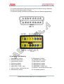
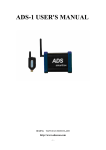
ADS9100
User manual
Dear user,
Thank you for purchasing ADS9100 (OBDII Break Out Box). This manual
contains introduction, function, usage and after-sale, please read it carefully
before using.
CONTENT
I. Introduction ................................................................................................ 01
II. Function .................................................................................................... 01
III. Usage ....................................................................................................... 03
IV. FAQ ............................................................................................................. 03
V. After-sale .................................................................................................... 04
I. Introduction
1.1 Overview of Test Box
OBDII Protocol Detector & Break Out Box has a wide range of applications in
diagnostics, key programming and chip tuning. It’s mainly used for changing
automotive diagnostic OBD stitch to signal judgment level transfer. It can
connect with any diagnostic instruments and judge whether car
communication is normal. Also it can supply car power during replacing the
battery , in order to prevent the body electrical equipment locked automatically.
II. Functio
2.1 Features of Test Box
·An extension of OBD Diagnostic Link Connector (DLC).
·For short circuiting of pins, to detect isolated circuits problems.
·Is a power extension cord for small DC testers that need an external power
source. (maximum 1.2 amps.
-1-
·To monitor data stream while performing test on vehicle using a Scantool.
·To test circuits with a meter or scope
·To perform special functions and tests as Ohm-out, Bench programming.
2.2 Indicator Light Meaning
1.
2.
3.
4.
5.
6.
7.
8.
Manufactory custom
SJE1850 wire<bus+>
Manufactory custom
Power grounding
Signal grounding
SAEJ2284《CAN》high
9. Manufactory custom
10. SJE1850 wire《bus->
11. Manufactory custom
12. Manufactory custom
13. Manufactory custom
14. SAEJ2284《CAN》low
ISO9141-2&iso, DIS4230-4K wire
15. ISO9141-2 & ISO/DIS 4230-4L wire
Manufactory custom
16. Car battery positive
-2-
III. Usage
1. Connect the OBD signal adaptor and the car diagnostic holder, NO. 4 and
NO.6 LED light,with 12V.
2. Supplying power to NO.4 negative pin and NO.6 positive pin. Then the OBD
adaptor can supply power to the car through diagnostic holder positive and
negative, to prevent car data losing and audio locking.
3. Remove the car battery.
4. Swift off the power and OBD adaptor in order to finish battery changing.
Remarks:
1) Connect it to the DLC (DATA LINK CONNECTOR) (OBD). As soon as you
connect it to DLC it automatically checks the power, grounds, DLC data wires
and searches for voltage pulses
2) Detecting Protocol in use: Plug your scan tool or interface into the OBDII
Protocol Detector & Break Out Box. Use the scan tool to view the live
datastream.
3) Check the flashing blue LEDs and match them with the protocols marked on
the main frame of the OBDII Protocol Detector & Break Out Box
Typical Applications:
VW - To protect the Scan tool such as aftermarket radios on VW's.
GM - Transmitter Programming on some GMs.
Honda - Set the ECM in SCS mode with your scan tool connected.
Lexus - Help diagnose electronics systems (Sirius, GPS) on pin 6 and 14.
Bosch - Troubleshoot Bosch controllers that short to ground.
IV. FAQ and solutions
1. Make sure the vehicle is parking and has electricity supply.
2. It’s non-waterproof, so don’t touch any more liquid like water and oil.
LEDs Activity:
OBDII Protocol Detector & Breakout Box LEDs allows you to keep tabs on
power and ground. It identifies the protocol used in the vehicle.
1) RED LEDs
·(Pin 16) - automatically turn-on as soon as you plugged into DLC.
RED LEDs turn dim when: Low battery voltage; wiring to DLC pin 16 is faulty;
grounds circuits has resistance issues.
2) GREEN LEDs
-3-
· (Pins 4 and 5) - automatically turn-on as soon as you plugged into DLC.
Ground LEDs (Pin 4 and 5) is connected to battery voltage through pin 16.
Therefore, a ground supply on pin 4 will not affect LED 5. A dim single green
LED will indicate a circuit problem with the corresponding circuit.
3) BLUE LEDs
·(Pins 2, 6, 7 and 10) - LEDs should flash when serial data voltage pulses are
present in the data line. Blue LEDs is assigned on pins 2, 6, 7 and 10 to
indicate communication with scan tool or interface and for communication
protocol identification. It will turn-on depending on your vehicle model. For
some vehicle models, none or multiple blue LEDs will turn-on as soon as the
Breakout Box is connected and you start the ignition.
·The brightness of the LEDs depends on the nature of the signal it's pursuing.
The Breakout Box can indentify immediately the protocol used. The better way
to indentify the protocol in use is to set-up the scan tool or interface in to LIVE
DATA. This will lead in a constant data stream between the scan tool and the
vehicle, and then you can locate the LEDs that are flashing.
· (Pins 1, 3, 8, 9, 11, 12, and 13) - it should flash when your vehicle
manufacturer uses either one on the pins for any function they prefer.
[ After Service ]
● Warranty: Within one year.
● URL: http://english.adsscan.com
● Tel/Fax: +86-755-89368397
● E-mail: [email protected]
-4-