1
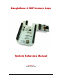
BeagleBone 3.1MP Camera Cape
System Reference Manual
Revision A2
October 12th, 2012
BeagleBone 3.1MP Camera Cape
System Reference Manual
Rev A1
THIS DOCUMENT
This work is licensed under the Creative Commons Attribution-Share Alike 3.0 Unported
License. To view a copy of this license, visit http://creativecommons.org/licenses/bysa/3.0/ or send a letter to Creative Commons, 171 Second Street, Suite 300, San
Francisco, California, 94105, USA.
All derivative works are to be attributed to BeagleBoardtoys.com.
For more information, see http://creativecommons.org/license/resultsone?license_code=by-sa
For any questions, concerns, or issues submit them to [email protected]
BEAGLEBONE 3.1MP CAMERA CAPE DESIGN
These design materials referred to in this document are
*NOT SUPPORTED* and DO NOT constitute a
reference design. Only “community” support is allowed via
resources at Beagleboardtoys.com/support
THERE IS NO WARRANTY FOR THE DESIGN
MATERIALS, TO THE EXTENT PERMITTED BY
APPLICABLE LAW. EXCEPT WHEN OTHERWISE
STATED IN WRITING THE COPYRIGHT HOLDERS
AND/OR OTHER PARTIES PROVIDE THE DESIGN
MATERIALS “AS IS” WITHOUT WARRANTY OF
ANY KIND, EITHER EXPRESSED OR IMPLIED,
INCLUDING, BUT NOT LIMITED TO, THE IMPLIED
WARRANTIES OF MERCHANTABILITY AND
FITNESS FOR A PARTICULAR PURPOSE. THE
ENTIRE RISK AS TO THE QUALITY AND
Page 2 of 26
BeagleBone 3.1MP Camera Cape
System Reference Manual
Rev A1
PERFORMANCE OF THE DESIGN MATERIALS IS
WITH YOU. SHOULD THE DESIGN MATERIALS
PROVE DEFECTIVE, YOU ASSUME THE COST OF
ALL NECESSARY SERVICING, REPAIR OR
CORRECTION.
We mean it; these design materials may be totally
unsuitable for any purposes.
Page 3 of 26
BeagleBone 3.1MP Camera Cape
System Reference Manual
Rev A1
BeagleBoardToys provides the enclosed product(s) under the following conditions:
This evaluation board/kit is intended for use for ENGINEERING DEVELOPMENT, DEMONSTRATION, OR
EVALUATION PURPOSES ONLY and is not considered by BeagleBoardtoys.com to be a finished endproduct fit for general consumer use. Persons handling the product(s) must have electronics training and
observe good engineering practice standards. As such, the goods being provided are not intended to be
complete in terms of required design-, marketing-, and/or manufacturing-related protective considerations,
including product safety and environmental measures typically found in end products that incorporate such
semiconductor components or circuit boards. This evaluation board/kit does not fall within the scope of the
European Union directives regarding electromagnetic compatibility, restricted substances (RoHS), recycling
(WEEE), FCC, CE or UL, and therefore may not meet the technical requirements of these directives or other
related directives.
Should this evaluation board/kit not meet the specifications indicated in the User’s Guide, the board/kit may
be returned within 30 days from the date of delivery for a full refund. THE FOREGOING WARRANTY IS
THE EXCLUSIVE WARRANTY MADE BY SELLER TO BUYER AND IS IN LIEU OF ALL OTHER
WARRANTIES, EXPRESSED, IMPLIED, OR STATUTORY, INCLUDING ANY WARRANTY OF
MERCHANTABILITY OR FITNESS FOR ANY PARTICULAR PURPOSE.
The user assumes all responsibility and liability for proper and safe handling of the goods. Further, the user
indemnifies BeagleBoardtoys.com from all claims arising from the handling or use of the goods. Due to the
open construction of the product, it is the user’s responsibility to take any and all appropriate precautions
with regard to electrostatic discharge.
EXCEPT TO THE EXTENT OF THE INDEMNITY SET FORTH ABOVE, NEITHER PARTY SHALL BE
LIABLE TO THE OTHER FOR ANY INDIRECT, SPECIAL, INCIDENTAL, OR CONSEQUENTIAL
DAMAGES.
BeagleBoardtoys.com currently deals with a variety of customers for products, and therefore our
arrangement with the user is not exclusive. BeagleBoardtoys.com assumes no liability for applications
assistance, customer product design, software performance, or infringement of patents or services
described herein.
Please read the User’s Guide and, specifically, the Warnings and Restrictions notice in the User’s Guide
prior to handling the product. This notice contains important safety information about temperatures and
voltages. For additional information on BeagleBoardtoys.com environmental and/or safety programs, please
contact visit BeagleBoardtoys.com.
No license is granted under any patent right or other intellectual property right of BeagleBoard.org covering
or relating to any machine, process, or combination in which such BeagleBoardtoys.com products or
services might be or are used.
Mailing Address:
Beagleboardtoys.com
1380 Presidential Dr. #100
Richardson, TX 75081
U.S.A.
Page 4 of 26
BeagleBone 3.1MP Camera Cape
System Reference Manual
Rev A1
WARRANTY: The BeagleBone 3.1MP Camera Cape is warranted against defects in materials and
workmanship for a period of 90 days from purchase. This warranty does not cover any problems
occurring as a result of improper use, modifications, exposure to water, excessive voltages, abuse,
or accidents. All boards will be returned via standard mail if an issue is found. If no issue is found
or express return is needed, the customer will pay all shipping costs.
Before returning the board, please visit Beagleboardtoys.com/support
To return a defective board, please request an RMA at
http://www.beagleboardtoys.com/support/rma
Page 5 of 26
BeagleBone 3.1MP Camera Cape
System Reference Manual
Rev A1
Table of Contents
FIGURES ...................................................................................................................................................... 7
TABLES ........................................................................................................................................................ 7
1.0
INTRODUCTION............................................................................................................................... 9
2.0
CHANGE HISTORY.........................................................................................................................10
2.1
2.2
3.0
CHANGE HISTORY ............................................................................................................................10
A1 VS. A2 ........................................................................................................................................10
BEAGLEBONE 3.1MP CAMERA CAPE OVERVIEW ..............................................................11
3.1 DESCRIPTIONS..................................................................................................................................11
3.2 IN THE BOX .....................................................................................................................................12
3.3 GETTING STARTED ...........................................................................................................................12
3.3.1
With LCD7 Cape ...................................................................................................................12
3.3.2
With DVI-D Cape ..................................................................................................................13
3.4 REPAIRS ...........................................................................................................................................14
4.0
FEATURES AND SPECIFICATIONS ............................................................................................15
4.1
4.2
4.3
4.4
4.5
4.6
4.7
4.8
5.0
KEY COMPONENT LOCATIONS .........................................................................................................16
EXPANSION BOARD AND SENSOR BOARD ........................................................................................16
CAMERA SENSOR .............................................................................................................................17
CSSP DEVICE ..................................................................................................................................17
CONNECTORS ...................................................................................................................................17
POWER INDICATOR ..........................................................................................................................17
MECHANICAL SPECIFICATIONS ........................................................................................................18
ELECTRICAL SPECIFICATIONS ..........................................................................................................18
SYSTEM ARCHITECTURE AND DESIGN ..................................................................................19
5.1 SYSTEM BLOCK DIAGRAM ...............................................................................................................19
5.2 3.1MP CAMERA SENSOR..................................................................................................................19
5.3 CAMERA INTERFACE (CAM I/F) ......................................................................................................21
5.4 GENERAL PURPOSE MEMORY CONTROLLER INTERFACE .................................................................21
5.5 POWER SUPPLY ................................................................................................................................23
5.6 VOLTAGE TRANSLATOR ...................................................................................................................23
5.7 EEPROM ........................................................................................................................................23
5.7.1
EEPROM Address .................................................................................................................24
5.7.2
I2C Bus ..................................................................................................................................24
6.0
MECHANICAL INFORMATION ...................................................................................................25
7.0
DESIGN MATERIALS .....................................................................................................................26
Page 6 of 26
BeagleBone 3.1MP Camera Cape
System Reference Manual
Rev A1
Figures
Figure 1.
Figure 2.
Figure 3.
Figure 4.
Figure 5.
Figure 6.
Figure 7.
Figure 8.
The BeagleBone 3.1MP Camera Cape ......................................................... 11
Key Components ........................................................................................... 16
BeagleBone 3.1MP Camera Cape High Level Block Diagram .................... 19
Camera sensor connector .............................................................................. 20
Camera interface ........................................................................................... 21
GPMC interface on CSSP device ................................................................. 22
BeagleBone 3.1MP Camera Cape EEPROM ............................................... 24
BeagleBone 3.1MP Camera Cape Dimensions Drawing ............................. 25
Tables
Table 1.
Table 2.
Change History ............................................................................................. 10
BeagleBone 3.1MP Camera Cape Features .................................................. 15
Page 7 of 26
BeagleBone 3.1MP Camera Cape
System Reference Manual
NOTES
Page 8 of 26
Rev A1
BeagleBone 3.1MP Camera Cape
1.0
System Reference Manual
Rev A1
Introduction
This document is the System Reference Manual for the BeagleBone 3.1MP Camera
Cape, an add-on board for the BeagleBone.
This document is intended as a guide to assist anyone purchasing or who are considering
purchasing the board to understand the overall design and usage of the BeagleBone
3.1MP Camera Cape from the system level perspective.
The design is subject to change without notice as we will work to keep improving the
design as the product matures.
The key sections in this document are:
Section 2.0 – Change History
Provides tracking for the changes made to the System Reference Manual.
Section 3.0 – Overview
This is a high level overview of the BeagleBone 3.1MP Camera Cape.
Section 4.0 – Features and Specification
Provided here are the features and electrical specifications of the board.
Section 5.0 – System Architecture and Design
This section provides information on the overall architecture and design of the
BeagleBone 3.1MP Camera Cape. This is a very detailed section that goes into
the design of each circuit on the board.
Section 6.0 – Mechanical
Information is provided here on the dimensions of the BeagleBone 3.1MP Camera
Cape.
Section 7.0 – Design Materials
This section provides information on where to get the design files.
Page 9 of 26
BeagleBone 3.1MP Camera Cape
2.0
Change History
2.1
Change History
System Reference Manual
Rev A1
Table 1 tracks the changes made for each revision of this document.
Table 1.
Rev
A1
A2
2.2
Change History
Changes
Initial release.
A1 vs. A2 (section 2.2)
Date
By
08/06/2012
10/20/2012
BBT
A1 vs. A2
The only change made in revision A2 is the QuickLogic chip CSSP-FPUN86-6494 has
been updated to a newer version to improve the support for the camera sensor. No
changes are made in the schematic, board files, or bill of materials.
Page 10 of 26
BBT
BeagleBone 3.1MP Camera Cape
System Reference Manual
3.0
BeagleBone 3.1MP Camera Cape Overview
3.1
Descriptions
Rev A1
The BeagleBone 3.1MP Camera Cape provides a portable camera solution for
BeagleBone. Each Camera Cape is composed of a Sensor board and an Expansion board.
The Sensor board carries a 3.1 megapixel camera sensor and transmits captured image
data to the Expansion board over camera interface (CAM I/F). The Expansion board
features a CSSP bridge connectivity device, which stores image data received from
Sensor board and transfers them to the AM335x using general purpose memory controller
(GPMC) interface.
Note: BeagleBone 3.1MP Camera Cape should be used with LCD7 Cape or DVI-D Cape
for previewing and capturing photos.
Figure 1 below is a picture of the board.
Figure 1.
The BeagleBone 3.1MP Camera Cape
Page 11 of 26
BeagleBone 3.1MP Camera Cape
3.2
System Reference Manual
Rev A1
In The Box
The final packaged BeagleBone 3.1MP Camera Cape product will contain the following
items:
- 1 BeagleBone 3.1MP Camera Cape
3.3
Getting Started
Note: BeagleBone 3.1MP Camera Cape should be used with LCD7 Cape or DVI-D Cape
for previewing and capturing photos.
3.3.1
With LCD7 Cape
Following the instructions below to start using your BeagleBone 3.1MP Camera Cape:
1) Ensure the EEPROM addresses on the LCD7 Cape and 3.1MP Camera Cape are
different.
Note: The EEPROM address is determined by the 2-bit switches SW1 on both
LCD7 and 3.1MP Camera capes. Ensure these two switches are configured
differently.
2) Mount the BeagleBone 3.1MP Camera to the connectors labeled “Cape Installed
Here”. Ensure BeagleBone is mounted to the other connectors.
3) Ensure the micro SD card using with BeagleBone has latest Angstrom image.
4) Power up the BeagleBone by connecting a 5V DC power supply to the DC
connector of LCD7 Cape.
5) The BeagleBone is now booting up. This process may take from 1 to 2 minutes.
LEDs D3 and D4 on LCD7 Cape and LEDs D1 and D2 on the Camera Cape
should be lit.
Note: For more information about LCD7 Cape, please visit its wiki page at
http://beagleboardtoys.com/wiki/index.php?title=BeagleBone_LCD7
6) After BeagleBone finishes booting up, you should see a desktop with black
background. This is the Angstrom desktop.
7) Go to the system menu bar at the top, select Applications > Sound & Video >
Cheese Webcam Booth to open the Cheese application.
Note: A stylus is recommended to use the Angstrom user interface on LCD7 Cape.
8) A live photo preview should be displayed at the center of Cheese application
window.
9) To capture a photo, click the “Take a Photo” button inside Cheese application
window.
Page 12 of 26
BeagleBone 3.1MP Camera Cape
3.3.2
System Reference Manual
Rev A1
With DVI-D Cape
Note: you will need an external USB mouse for navigating the system menu on the DVI-D
supported monitor.
Following the instructions below to start using your BeagleBone 3.1MP Camera Cape:
1) Ensure the EEPROM addresses on the DVI-D Cape and 3.1MP Camera Cape are
different.
Note: The EEPROM address is determined by the 2-bit switches SW1 on both
DVI-D and 3.1MP Camera capes. Ensure these two switches are configured
differently.
2) Mount the BeagleBone 3.1MP Camera Cape and DVI-D Cape on a BeagleBone.
The mounting order is not important.
3) Connect a HDMI-to-DVI cable from the HDMI connector of DVI-D Cape to a
DVI-D supported monitor.
Note: For more information about DVI-D Cape, please visit its wiki page at
http://beagleboardtoys.com/wiki/index.php?title=BeagleBone_DVI-D
4) Connect a USB mouse to the USB host connector P2 of BeagleBone.
Note: Certain USB mice are not compatible with BeagleBone Angstrom software.
5) Ensure the micro SD card using with BeagleBone has latest Angstrom image.
6) Power up the BeagleBone by connecting a 5V DC power supply to the DC
connector of BeagleBone.
7) The BeagleBone is now booting up. This process may take from 1 to 2 minutes.
LEDs D5 and D6 on DVI-D Cape and LEDs D1 and D2 on the Camera Cape
should be lit.
8) After BeagleBone finishes booting up, you should see a desktop with black
background on the monitor. This is the Angstrom desktop.
9) Go to the system menu bar at the top, select Applications > Sound & Video >
Cheese Webcam Booth to open the Cheese application.
10) A live photo preview should be displayed at the center of Cheese application
window.
11) To capture a photo, click the “Take a Photo” button inside Cheese application
window.
Page 13 of 26
BeagleBone 3.1MP Camera Cape
3.4
System Reference Manual
Rev A1
Repairs
If you feel the board is in need of repair, follow the RMA Request process found at
http://www.beagleboardtoys.com/support/rma
Do not send the board in for repair until an RMA
authorization has been provided.
Do not return the board to the distributor unless you want to get a refund. You must get
authorization from the distributor before returning the board.
Page 14 of 26
BeagleBone 3.1MP Camera Cape
4.0
System Reference Manual
Rev A1
Features and Specifications
This section covers the specifications of the BeagleBone 3.1MP Camera Cape and
provides a high level description of the major components and interfaces that make up the
board.
Table 2 provides a list of the BeagleBone 3.1MP Camera Cape’s features.
Table 2.
Camera Sensor
Data Interface
Power
Indicator
Connectors
BeagleBone 3.1MP Camera Cape Features
1/4 inch 3.1 megapixel Aptina MT9T111
CAM I/F
GPMC
3.3V via expansion header
5V via expansion header
Two Power LEDs
Two 46-position BeagleBone connectors
One 10-position BeagleBone connector
Two pairs of 30-position Sensor board connectors
One 28-position camera sensor socket
Page 15 of 26
BeagleBone 3.1MP Camera Cape
4.1
System Reference Manual
Rev A1
Key Component Locations
Figure 2 shows the location of the key components on the board.
Figure 2.
4.2
Key Components
Expansion Board and Sensor Board
The BeagleBone 3.1MP Camera Cape is composed of an Expansion board and a Sensor
board. The Expansion board provides BeagleBone the capability to connect to a camera
sensor via camera interface (CAM I/F). The Expansion board carries QuickLogic CSSP
device which receives processed camera data from camera sensor and transmits these
data to BeagleBone via GPMC bus. The Expansion board, powered by the BeagleBone,
also provides different power supplies to the CSSP device as well as the Sensor board.
The Expansion board mounts directly to BeagleBone via its stackable connectors.
The Sensor board, on the other hand, is mated to Expansion board via two 30-position
connectors. The Sensor board also features a 28-position socket to connect to camera
sensor. The BeagleBone 3.1MP Camera Cape uses MT9T111 camera sensor; however,
other sensors with the same interface can also be used. The Sensor board also includes an
EEPROM to store board information, which is required by BeagleBone for cape
identification and pin muxing configuration.
Page 16 of 26
BeagleBone 3.1MP Camera Cape
4.3
System Reference Manual
Rev A1
Camera Sensor
The BeagleBone 3.1MP Camera Cape uses Aptina camera sensor MT9T111, which is a
1/4 inch 3.1 megapixel system-on-a-chip (SOC) image sensor. MT9T111 features an
integrated image processor to process the acquired image then transmits the processed
data to QuickLogic CSSP chip. The data is transmitted in RAW 10-bit Bayer format.
4.4
CSSP Device
The CSSP bridge connectivity device, an 86-pin thin profile fine pitch ball grid array
(TFBGA), is a Customer Specific Standard Product by QuickLogic. This device provides
camera interface (CAM I/F) to connect to the 3.1MP camera sensor. The camera image
data is received and stored by the CSSP device before being transmitted to the
BeagleBone over GPMC interface.
4.5
Connectors
There are three stackable connectors on the BeagleBone 3.1MP Camera Cape. The 46position and 20-position connectors will stack on top of the expansion connectors of
BeagleBone. The 10-position connector will stack on top of the backlight expansion
connector of BeagleBone.
The 3.1MP Camera Cape also uses two pairs of 30-position connector to connect the
Expansion board and Sensor board. A 28-position socket is located on the Sensor board
for camera sensor connection.
4.6
Power Indicator
The BeagleBone 3.1MP Camera Cape features two LEDs to indicate that power rail 1.8V
and 2.8V are applied to the cape. These LEDs are green when lit.
Page 17 of 26
BeagleBone 3.1MP Camera Cape
4.7
Rev A1
Mechanical Specifications
Size:
Layers:
PCB thickness:
RoHS Compliant:
4.8
System Reference Manual
3.40” x 3.90”
4
.062”
Yes
Electrical Specifications
Table 3 is the electrical specification of the external interfaces to the BeagleBone 3.1MP
Camera panel.
Table 3.
BeagleBone 3.1MP Camera Electrical Specifications
Specification
Min
Typ
Max
Unit
Power
Input Voltage DC
3.3
5.0
V
V
Environmental
Temperature range
0
Page 18 of 26
+85
C
BeagleBone 3.1MP Camera Cape
5.0
System Reference Manual
Rev A1
System Architecture and Design
This section provides a high level description of the design of the BeagleBone 3.1MP
Camera Cape and its overall architecture.
5.1
System Block Diagram
Figure 3 is the high level block diagram of the BeagleBone 3.1MP Camera Cape.
P1
16
B
E
A
G
L
E
5
GPMC_AD
GPMC_CONTROL
2
EEPROM
DMAR
EEPROM ADDR
C
O
N
N
EEPROM ADDR
10 CAM_D
10 CAM_D
3 CAM_CTRL
3V3_EXP
P1
B
E
A
G
L
E
C
O
N
N
U1
TPS73701
LDO
1V8
U4
CSSP-FPUN86-XXXX
LDO_EN
2V8
CSSP BRIDGE CONNECTIVITY
DEVICE
3 CAM_CTRL
J3 & J4
RESET
I2C2
U1
TPS73701
LDO
CAM_MCLK
DUAL
SENSOR
BOARD
CONN
J1
RESET
I2C2
CAMERA
SENSOR
CONN
CAM_MCLK
GPIO0_30
RESET
2
Figure 3.
5.2
U5
2
SW1
BeagleBone 3.1MP Camera Cape High Level Block Diagram
3.1MP Camera Sensor
The 3.1 megapixel on the BeagleBone 3.1MP Camera Cape is an Aptina CMOS digital
image sensor, MT9T111, which integrates on-chip camera function and is programmable
through serial interface. MT9T111 is capable to be a stand-alone camera solution that
includes both image acquisition and processing. Followings are some feature highlights
of MT9T111 camera sensor:
Page 19 of 26
BeagleBone 3.1MP Camera Cape
-
System Reference Manual
Rev A1
1024 x 768 YUV output with maximum frame rate of 30 frames per second
(fps)
2048 x 1536 JPEG output with maximum frame rate of 15 fps
Anti-shake and auto focus
Hard standby with or without memory retention
Soft standby with memory retention
The MT9T111 receives its master clock (CAM_MCLK) and an active-low hard reset
signal (CAM_RESET) directly from the BeagleBone. This clock signal is used as a
reference to generate the pixel clock (CAM_PCLK) for parallel output data bus to CSSP
device. In RAW 10-bit Bayer format, the Dout[7:0] signals represents the highest
significant output data bits CAM_D[9:2] while the lowest two are output on GPIO[1:0]
signals. Internal registers and variables can be programmed via MT9T111 two-wire
interface (I2C2_SCL and I2C2_SDA).
Figure 4 shows camera sensor connector J1 on the Camera Sensor board.
Figure 4.
Camera sensor connector
Page 20 of 26
BeagleBone 3.1MP Camera Cape
5.3
System Reference Manual
Rev A1
Camera Interface (CAM I/F)
The CSSP device uses CAM I/F to connect to Aptina camera sensor chip. This interface
supports transmitting camera data in RAW 10-bit Bayer pattern format up to 12 fps. After
CAM_HSYNC and CAM_VSYNC signals have been asserted, 10-bit camera output data
is transmitted from the camera sensor and to a 512-word FIFO of CSSP device. This
transmission is clocked by the camera sensor output pixel clock signal (CAM_PCLK).
All signals are at 2.8V voltage level.
Figure 5 below shows the camera interface on the CSSP device.
Figure 5.
5.4
Camera interface
General Purpose Memory Controller Interface
The GPMC is a 16-bit external memory controller, which is used for communication
between standard memories and a wide range of external devices. The connection
between the GPMC and CSSP devices is a 16-bit synchronous address/data-multiplexed.
After the CSSP FIFO is filled with 128 words of camera data, the CSSP device will assert
the DMA request signal (DMAR) to start transferring data to the BeagleBone AM335x.
The data is transferred from the FIFO as 16-bit, which consists of RAW 10-bit Bayer data
as lower 10-bit and zeros as the upper 6 bits. The transfer is clocked by a 48MHz GPMC
clock signal (GPMC_CLK) provided by the AM335x.
Figure 6 shows the GPMC interface on CSSP device.
Page 21 of 26
BeagleBone 3.1MP Camera Cape
Figure 6.
System Reference Manual
GPMC interface on CSSP device
Page 22 of 26
Rev A1
BeagleBone 3.1MP Camera Cape
5.5
System Reference Manual
Rev A1
Power Supply
The BeagleBone Camera Cape generates 1.8V and 2.8V power supplies for I/O signals of
CSSP device as well as the camera sensor. Two low-dropout (LDO) voltage regulators
TPS73701 are used to regulate VDD_1V8 and VDD_2V8 power rails. The LDO’s are on
when their enable pins are pulled high and go to shutdown mode when the enable inputs
are low. These enable pins are controlled by a GPIO signal, GPIO0_5, which can be
accessed at pin 17 of P2 connector.
5.6
Voltage Translator
Voltage translations are required on the Sensor board to bring the signals from
BeagleBone down to the voltage level of camera sensor. These signals include the I2C2
bus, CAM_RST, and CAM_MCLK.
5.7
EEPROM
The BeagleBone 3.1MP Camera Cape has an EEPROM containing information that will
allow the SW to identify the board and to configure the expansion headers pins as
needed. EEPROMs are required for all Capes sold in order for them to operate correctly
when plugged in the BeagleBone.
The EEPROM used on this cape is the same one as is used on the BeagleBone, a
CAT24C256. The CAT24C256 is a 256 kb Serial CMOS EEPROM, internally organized
as 32,768 words of 8 bits each. It features a 64-byte page write buffer and supports the
Standard (100 kHz), Fast (400 kHz) and Fast-Plus (1 MHz) I2C protocol. Figure 7 is the
design of the EEPROM circuit.
Page 23 of 26
BeagleBone 3.1MP Camera Cape
Figure 7.
5.7.1
System Reference Manual
Rev A1
BeagleBone 3.1MP Camera Cape EEPROM
EEPROM Address
In order for each Cape to have a unique address, a board ID scheme is used that sets the
address to be different depending on the order in which it is stacked onto the main board.
A two position dipswitch or jumpers is used to set the address pins of the EEPROM. It is
the responsibility of user to set the proper address for each board. Address line A2 is
always tied high. This sets the allowable address range for the expansion cards to 0x54 to
0x57.All other I2C addresses can be used by the user in the design of their Capes. But,
these addresses must not be used other than for the board EEPROM information. On the
BeagleBone 3.1MP Camera Cape, the EEPROM address switch is located on the
Expansion board, whereas the EEPROM IC is on the Sensor board.
5.7.2
I2C Bus
The EEPROMs on each expansion board is connected to I2C2. For this reason I2C2 must
always be left connected and should not be changed by SW to remove it from the
expansion header pin mux. The I2C signals require pull-up resistors. Each board must
have a 5.6K resistor on these signals. With four resistors this will be an affective
resistance of 1.4K if all Capes were installed.
Page 24 of 26
BeagleBone 3.1MP Camera Cape
6.0
System Reference Manual
Rev A1
Mechanical Information
This section provides information on the mechanical aspect of the BeagleBone 3.1MP
Camera Cape.
Figure 8 is the dimensions of the BeagleBone 3.1MP Camera Cape.
Figure 8.
BeagleBone 3.1MP Camera Cape Dimensions Drawing
Page 25 of 26
BeagleBone 3.1MP Camera Cape
7.0
System Reference Manual
Rev A1
Design Materials
Design information can be found at BeagleBoardToys wiki:
http://beagleboardtoys.com/wiki/index.php?title=BeagleBone_3.1MP_Camera
Provided there is:
- Schematic in PDF
- Schematic in OrCAD
- Manufacturing files
o PCB Gerber
o PCB Layout (Allegro)
- Bill of Materials
- System Reference Manual (This document)
These design materials are *NOT SUPPORTED* and DO NOT constitute a reference
design. Only “community” support is allowed via resources at BeagleBoard.org/discuss.
THERE IS NO WARRANTY FOR THE DESIGN MATERIALS, TO THE EXTENT
PERMITTED BY APPLICABLE LAW. EXCEPT WHEN OTHERWISE STATED IN
WRITING THE COPYRIGHT HOLDERS AND/OR OTHER PARTIES PROVIDE THE
DESIGN MATERIALS “AS IS” WITHOUT WARRANTY OF ANY KIND, EITHER
EXPRESSED OR IMPLIED, INCLUDING, BUT NOT LIMITED TO, THE IMPLIED
WARRANTIES OF MERCHANTABILITY AND FITNESS FOR A PARTICULAR
PURPOSE. THE ENTIRE RISK AS TO THE QUALITY AND PERFORMANCE OF THE
DESIGN MATERIALS IS WITH YOU. SHOULD THE DESIGN MATERIALS PROVE
DEFECTIVE, YOU ASSUME THE COST OF ALL NECESSARY SERVICING, REPAIR
OR CORRECTION.
We mean it, these design materials may be totally unsuitable for any purposes.
Page 26 of 26