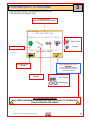
1
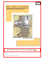
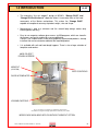
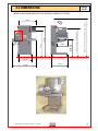
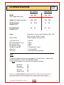
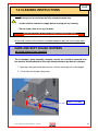
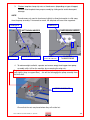
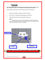
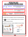
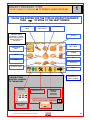
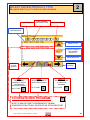
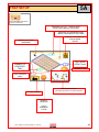
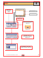
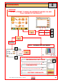
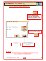
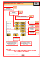
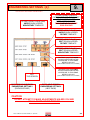
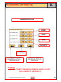
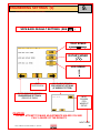
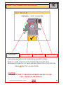
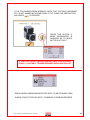
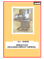
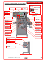
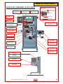
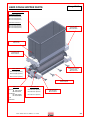
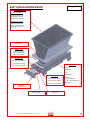
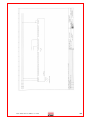
Enter Serial No. here.
MANUAL No.Y-OM-03E
In the event of an enquiry please quote this serial number.
Store this document safely and ensure it is available at all times.
Non-availability may affect the service / repair of your machine.
OPERATING AND MAINTENANCE
MANUAL
“OMEGA PLUS”
INCLUDING WIRECUT VERSION
DEPOSITOR
(400, 450,)
07/12
Omega
PLUS
Failure to adhere to the cleaning and
maintenance instructions detailed in this booklet
could affect the warranty of this machine.
WIRECUT VERSION
FOR SAFE WORKING, PAY SPECIAL ATTENTION TO ITEMS MARKED
FG079 –OMEGA TOUCH INCL WIRECUT 09/12 RAC
3
CONTENTS
1.0
-
INTRODUCTION
2.0
-
DIMENSIONS
3.0
-
SPECIFICATIONS
4.0
-
SAFETY
5.0
-
INSTALLATION
6.0
-
ISOLATION
7.0
-
CLEANING INSTRUCTIONS
8.0
-
OPERATING CONDITIONS
9.0
-
PREPARING FOR OPERATION
Omega
PLUS
9A – FITTING THE HOPPER
9B – FITTING A TEMPLATE
10.0
-
OPERATING INSTRUCTIONS
1
– SELECT PRODUCT TYPE
2
– SELECT SAVED NAME OF PRODUCT TYPE
3
– CONFIRM SETUP
4
– OPERATOR SCREEN
5
– EDIT SCREEN
5A – TRAY SETUP
6
– COPY
7
– DELETE
8
– PASSWORDS
9
– ENGINEERING SETTINGS
10 – FAULT INFORMATION SCREENS
11.0
-
MAINTENANCE
12.0
-
SPARES AND SERVICE
13.0
-
SPARES LIST
14.0
-
ELECTRICAL INFORMATION
FG079 –OMEGA TOUCH INCL WIRECUT 09/12 RAC
CHECK AND MAINTENANCE SCHEDULE
4
Omega
PLUS
1.0 INTRODUCTION
•
The innovative “five axis deposit” design of MONO’s “Omega PLUS” and
“Omega PLUS with wirecut” depositor allows it to recreate most of the hand
movements of the Master confectioner. This makes the “Omega PLUS”
capable of exceptional accuracy of product weight, size and shape.
•
Maintenance is kept to a minimum and the smooth body design makes daily
cleaning quick and easy.
•
Easy to use computer software gives access to 650 programs, which are stored in
the memory and easily recalled for use or modification.
Control is via a colour touch screen with graphically represented products, already
installed, that can be created or edited to the required product.
•
It is available with soft and hard dough hoppers. There is also a large selection of
templates and nozzles.
HARD OR SOFT
DOUGH HOPPERS
WIRECUT
(IF FITTED)
EASY CONTROLS
SLIDE IN TEMPLATES
LOCKING CASTORS
As it is our policy to improve our machines continuously,
we reserve the right to change specifications without prior notice
MODELS ARE AVAILABLE WITH OR WITHOUT WIRECUT OPTION
FG079 –OMEGA TOUCH INCL WIRECUT 09/12 RAC
5
Omega
PLUS
2.0 DIMENSIONS
MODELS ARE AVAILABLE WITH OR WITHOUT WIRECUT OPTION
1981mm (400mm + 450mm Extended capacity hopper)
470mm
898mm MAX
818mm MIN
1330mm
1510mm
WIRECUT
1451mm (extended capacity hopper)
890mm
690mm
1210mm
FG079 –OMEGA TOUCH INCL WIRECUT 09/12 RAC
856mm
6
Omega
PLUS
3.0 SPECIFICATIONS
SOFT DOUGH
HARD DOUGH
MODEL
(Nom. hopper width (mm))
400
450
400
450
Weight (with hopper fitted) (kg) :
196
210
216
235
Standard hopper
Capacity (litre) :
20
22.5
21
24
Extended hopper
Capacity (litre) :
36
41
31
35
Power:
MAX RATING
Single phase, 13A max load.Suitable for 200v, 220v,
230v, and 240v, 50-60 Hz supply.
2.5kW single phase fused at 13A
Cycles per minute
Min distance between trays
Max vertical travel
Max program storage
Number of languages
Noise level
Electronics
= Up to 35
= 50mm
= 80mm
= 650
= 13 (additional in future)
= Less than 85dB
= All microprocessor controlled
NOTE:
The minimum deposit that can be made depends on several factors - recipe, mixing
method, template size, nozzle size and deposit speed.
As a guide the following is the minimum that should be attempted:
Macaroons
Meringues
Choux Paste
Viennese
Sponge Drops
6g,
3g,
5g,
4g,
4g.
However, consult Mono Equipment if intended product falls outside the above general machine
specification to determine the exact capabilities of the “Omega” with any specific product.
As it is our policy to improve our machines continuously, we reserve the right to change specifications without prior notice
FG079 –OMEGA TOUCH INCL WIRECUT 09/12 RAC
7
4.0 SAFETY
Omega
PLUS
1
Never use a machine in a faulty condition and always report any damage.
2
Only trained engineers may remove parts that need a tool to remove them.
3
Always ensure hands are dry before touching any electrical appliance (including
cable, switch and plug). NEVER move machinery by pulling on the power cords
or cables.
4
Ensure that the floor area around the OMEGA is clean to avoid slipping –
especially if carrying heavy hopper and template components to and from the
machine.
5
All operatives must be fully trained.
Use of the machine can prove dangerous if:
the machine is operated by untrained or unskilled staff
the machine is not used for its intended purpose
the machine is not operated correctly
All safety devices applied to the machine during manufacture and the
operating instructions in this manual are required to operate this
machine safely. The owner and the operator are responsible for
operating this machine safely.
6
People undergoing training on the machine must be under direct supervision.
7
Do not operate the machine with any panels or guards removed.
8
No loose clothing or jewellery should be worn while operating the machine.
9
Switch off power at the mains isolator when machine is not in use and before
carrying out any cleaning or maintenance.
FG079 –OMEGA TOUCH INCL WIRECUT 09/12 RAC
8
Omega
PLUS
10 The bakery manager or the bakery supervisor should carry out daily safety
checks on the machine.
11 Do not operate machine without hopper template and guard fitted correctly.
(11) HOPPER TEMPLATE AND
GUARD FITTED
12 Due to the essential requirement for handling heavy components during cleaning,
it is recommended that protective footwear be worn when carrying out such
procedures.
ALL CLEANING AND MAINTENANCE OPERATIONS MUST
BE MADE WITH THE MACHINE DISCONNECTED FROM
THE POWER SUPPLY.
FG079 –OMEGA TOUCH INCL WIRECUT 09/12 RAC
9
Omega
PLUS
5.0 INSTALLATION
1
Ensure that the depositor is connected to correct electric supply, as specified on the
serial number plate on the side of the machine.
2
Ensure that the correct fuse rating is fitted in the electrical supply
6.0 ISOLATION
IN AN EMERGENCY, SWITCH OFF AT THE
ELECTRICAL MAINS WALL ISOLATOR, OR
PUSH THE EMERGENCY STOP BUTTON.
To release the emergency stop button, turn clockwise.
STOP BUTTON
FG079 –OMEGA TOUCH INCL WIRECUT 09/12 RAC
10
Omega
PLUS
7.0 CLEANING INSTRUCTIONS
NOTE:
- Cleaning must be carried out by fully trained personnel only.
- Isolate machine from mains supply before carrying out any cleaning.
- Do not steam clean or use a jet of water.
-Do not use any form of caustic detergent or abrasive cleaners. -
All the outer surfaces of the machine should be wiped over daily with warm soapy water.
HARD AND SOFT DOUGH HOPPERS
BETWEEN PRODUCT MIX CHANGES
The feed hopper, pump assembly, template, nozzles etc. should be removed from
the machine and dismantled for thorough cleaning between product mix changes.
1. Open top safety guard and remove excess mixture remaining in the feed hopper.
2. Lift off front see-through safety cover.
SAFETY COVER
FG079 –OMEGA TOUCH INCL WIRECUT 09/12 RAC
11
3.
Slacken template clamp strip nuts or thumbscrews (depending on type of hopper)
Remove fitted template from pump assembly by sliding out to avoid subsequent
damage.
NOTE.
Thumbscrews only need to be released slightly to allow the template to slide away
from the pump assembly. If loosened too much, the template will have to be supported.
TEMPLATE
TEMPLATE
SOFT DOUGH HOPPER
NOZZLES
CLAMP STRIP NUTS
HARD DOUGH HOPPER
DIES
(FITTED TO TEMPLATE)
CLAMPING
THUMBSCREWS
4
To reduce weight and bulk, separate and remove empty feed hopper from pump
assembly, whilst still on the machine, by unscrewing the wing nuts.
To gain access to the inner wing nut, slide the complete hopper away from the machine
body slightly (keep on support bars) - this will also disengage the pump assembly from
the drive shaft.
HOPPER WINGNUTS
Ensure that the nuts are placed where they will not be lost.
FG079 –OMEGA TOUCH INCL WIRECUT 09/12 RAC
12
Omega
PLUS
SOFT DOUGH HOPPER
CAUTION:
The feed hopper and pump assembly exceeds 25kg and will need to be lifted off by
two people, or dismantled into smaller components while still on the machine.
Take care to avoid damage to the sealing surface of the feed hopper during removal,
cleaning, assembly and storage.
1. After removing the feed hopper, check condition of feed hopper seal.
2. Unscrew the end cap retaining nuts from the accessible side of the pump assembly.
[Ensure that the nuts are placed where they will not be lost.]
FEED HOPPER
SEALING SURFACE
ENDCAP NUTS
3. Withdraw the end-cap with the pump gears.
Ensure that the ‘O’ sealing ring on the inside of the end cap is not damaged during cleaning.
‘O’ RING IN GROOVE
END CAP
PUMP GEARS
REMOVE WITH END CAP
(NOT SHOWN)
4. Remove remainder of pump assembly from the machine and remove
remaining end-cap to fully dismantle pump assembly components for cleaning.
FG079 –OMEGA TOUCH INCL WIRECUT 09/12 RAC
13
Omega
PLUS
HARD DOUGH HOPPER
CAUTION:
The feed hopper and pump assembly exceeds 25kg and will need to be lifted off by
two people, or dismantled into smaller components while still on the machine.
To reduce weight and bulk, separate and remove empty feed hopper from pump
assembly, whilst still on the machine, by unscrewing the wing nuts.
(Ensure that the nuts are placed where they will not be lost.)
The pump assembly will now be lighter and more easily removed.
1.
Lift off both upper plastic end-caps.
2.
Remove both gears from the assembly, one at a time, by lifting vertically.
3.
Remove remainder of pump assembly from the machine for cleaning.
END CAP
END CAP
WING NUTS
To gain access to the inner wing nut,
slide the complete hopper away from
the machine body slightly (keep on
support bars) - this will also
disengage the pump assembly from
the drive shaft.
NOTE:
Use only warm soapy water to clean these parts. They should be rinsed and
thoroughly dried before re-assembly.
The greatest care must be taken not to drop any parts.
Do not leave any components in the hopper.
FG079 –OMEGA TOUCH INCL WIRECUT 09/12 RAC
14
8.0
OPERATING CONDITIONS
Omega
PLUS
To obtain the best product results and consistent operation,
Make sure the depositor is used on a level floor.
Ensure flat trays of consistent length, width, material
and edge dimensions are used.
Ensure undamaged nozzles and templates are used.
Keep the machine clean.
FG079 –OMEGA TOUCH INCL WIRECUT 09/12 RAC
15
Omega
PLUS
9.0 PREPARING FOR OPERATION
1
Select template and nozzles (and finger frame, if wirecut is to be used) and fit as
section 9a & 9b (following pages). Fill hopper with mix and close hopper cover.
It is recommended that when heavy mixes are used, the inside of the hopper should be
coated with vegetable oil; for lighter mixes such as meringue, dampen with water. The oil
or water will help the mix to settle down the hopper walls and prevent air being sucked in.
LIFT COVER
SCREEN
HOPPER
STOP BUTTON
TEMPLATE
2
Connect power cable to electrical supply.
Make sure stop button is in released position (turn clockwise if required).
3
Select an existing program or create a new program through the on-screen menus.
(see section 10 operation)
4
The machine is now ready for operation.
FG079 –OMEGA TOUCH INCL WIRECUT 09/12 RAC
16
9a
Omega
PLUS
FITTING THE HOPPER
CAUTION SHOULD BE TAKEN WHEN FITTING THE HOPPER
AND PUMP ASSEMBLY, AS WEIGHT EXCEEDS 25kgs ON SOME MODELS
It will need to be lifted on by two people, or
dismantled into smaller components before fitting on the machine.
MAKE SURE THE FLOOR AREA AROUND THE MACHINE IS CLEAN
To reduce weight and bulk, fit the complete hopper assembly in two stages - first the
pump assembly onto the support bars, then the feed hopper body onto the pump
assembly.
1
By hand, align pump assembly drive gear roller with drive shaft on machine.
2
Fit hopper to pump assembly and secure with wing nuts.
3
Slide hopper on support bars until fully up against machine.
FEED HOPPER
FEED HOPPER
WING NUTS
(EACH END)
PUMP ASSEMBLY
SUPPORT BARS
HARD DOUGH
4
SOFT DOUGH
After the hopper is fitted, the safety cover MUST BE replaced with the reflector
facing towards the machine body.
SAFETY COVER
REFLECTOR
DO NOT OPERATE MACHINE WITHOUT TEMPLATE FITTED
FG079 –OMEGA TOUCH INCL WIRECUT 09/12 RAC
17
9b
Omega
PLUS
FITTING A TEMPLATE
• Soft dough
Non-rotary templates can be fitted with nozzles. This requires screwing the
nozzles into the threaded holes provided.
Rotary templates can have plastic nozzles screwed into nozzle holders
(straight or offset).
OR
Metal nozzles secured in place by a separate nut.
1
Select template and nozzles required.
(Nozzles are not required for sheeting, staggered or stub templates)
2
Attach nozzles to template body:
RECESS FOR TEMPLATE
TEMPLATE
BODY
NOZZLES
CLAMP STRIP NUTS
3
Slide the template into the matching recess at the base of the pump assembly until
the stop is in position.
4
Tighten the nuts on the clamp strip (on underside of pump assembly) to secure
template.
NOTE. If the nuts are not securely tightened, leakage of mix will occur,
affecting deposit weights.
DO NOT OPERATE MACHINE WITHOUT TEMPLATE FITTED
BEFORE USING STRAIGHT & OFFSET NOZZLE HOLDERS
“O” RINGS MUST BE FITTED
Nozzle holders provide the means of attaching standard plastic nozzles to the soft dough rotary templates and the
sealing rings need to be fitted before using and may need replacing occasionally to ensure correct operation.
“O” RING PART NUMBER = A900-12-010 (SUPPLIED IN BAGS OF 20)
LOOP FIRST RING OVER END
SLIDE RING DOWN TO GROOVE
FIRST RING IN CORRECT POSITION
LOOP SECOND RING OVER END
SLIDE RING DOWN TO SECOND GROOVE,
PASSING OVER FIRST RING
SECOND RING IN CORRECT POSITION
FG079 –OMEGA TOUCH INCL WIRECUT 09/12 RAC
19
• Hard dough
Non-rotary templates that can be fitted with nozzles require them to be secured in place
with a separate nut. Nozzles are not required for sheeting or wirecut templates.
Rotary templates require nozzles to be secured in place with a separate nut.
1
Select wirecut template or template and nozzles required.
2
Attach nozzles (if required) to template body using special nut:
3
Slide template into position and hand-tighten thumbscrews.
NOTE.
Thumbscrews only need to be released slightly to allow the template to
slide away from the pump assembly. If loosened too much the template will have
to be supported while the screws are tightened.
TEMPLATE
DIES
4
(FITTED TO TEMPLATE)
CLAMPING
THUMBSCREWS
DO NOT OPERATE MACHINE WITHOUT TEMPLATE FITTED
FG079 –OMEGA TOUCH INCL WIRECUT 09/12 RAC
20
IF WIRECUT FITTED
FITTING WIRECUT FINGERS
1.
Select wirecut fingers that suit the chosen template to be used.i.e. the correct
number to match the number of dies across template.
2.
Remove drop arm pins and insert finger frame into arms. Ensure that the
follower arm roller is positioned on the cam track.
FOLLOWER ARM
ROLLER
DROP ARM PINS
3.
Replace drop arm pins.
4.
Disconnect motor release knob and push fingers forward in order to line up the
wire with the dies.
MOTOR RELEASE KNOB
FINGER ADJUSTING BOLTS
5.
Adjust individual finger bolts to raise the wire to touch the bottom surface of the
dies used in the template.
OR
Adjust the spring loaded screw to raise or lower all fingers at the same time.
SPRING LOADED ADJUSTMENT SCREW
FG079 –OMEGA TOUCH INCL WIRECUT 09/12 RAC
21
IF WIRECUT FITTED
REPLACING BROKEN WIRE
MAKE SURE THAT ALL PIECES OF WIRE HAVE BEEN FOUND BEFORE
OPERATING MACHINE AFTER A WIRE REPLACEMENT.
1.
Remove fingers from the machine.
2.
Remove broken wire
3.
Feed new wire round screw between washers and tighten screw.
4.
Feed the wire through the eyehole in the end of each finger.
5.
Feed new wire round other screw between washers. Pull tight and tighten
screw. (wire should be like a guitar string).
6.
Replace the fingers back in the machine and check set up and operation.
FIXING
SCREW
WIRE
FIXING
SCREW
FIXING
SCREW
FG079 –OMEGA TOUCH INCL WIRECUT 09/12 RAC
22
10.0
‘OMEGA PLUS’
FG079 –OMEGA TOUCH INCL WIRECUT 09/12 RAC
OPERATION
Omega
PLUS
23
OPERATING KEY
FOR FOLLOWING INSTRUCTIONS
BLUE
RED
=
=
OPERATION
FOLLOW BLUE ARROWS AND BOXES TO
OPERATE THE DEPOSITOR WITH ALREADY
SAVED PROGRAMS
CHANGE SETTINGS
=
KEYBOARD ENTRY
REQUIRED
FOLLOW RED ARROWS AND BOXES TO
CHANGE SETTINGS AND CREATE NEW
PROGRAMS
WHEN KEYBOARD APPEARS, A CODE
MUST BE ENTERED BY TOUCHING THE
NUMBERS IN THE CORRECT ORDER
IF A GREY BOX IS SHOWN IN THE BUTTON DESCRIPTION
e.g.
7
GO TO THE CORRESPONDING PAGE FURTHER
ON IN THE INSTRUCTIONS.
(MARKED IN TOP RIGHT HAND CORNER OF EACH PAGE)
FG079 –OMEGA TOUCH INCL WIRECUT 09/12 RAC
24
SELECT PRODUCT TYPE
1
SELECT PRODUCT TO DEPOSIT OR TO CREATE A NEW PROGRAM
TOUCH THE SCREEN FOR THE TYPE OF PRODUCT REQUIRED
THEN
TO MOVE TO THE NEXT SCREEN
STRIP WITH
TWIST
MULTIDROP
WITH TWIST
MULTIDROP
HIGHLIGHT BOX
APPEARS TO SHOW
SELECTED PRODUCT
WHEN SCREEN IS
TOUCHED
SPIRAL
TOWER
WITH TWIST
DROP WITH
TWIST
TOWER
DROP
ARC
STRIP
SHEETING
REVERSE STRIP
SHELL
PROGRESS TO
NEXT SCREEN
THESE BUTTONS
CONTROL CHANGES
TO THE MACHINE
CHOOSE
LANGUAGE
MACHINE SETUP
PRODUCT
EDITING
COPYING
DELETING
PASSWORDS ARE REQUIRED FOR
THESE FUNCTIONS. SEE PART 8 8
BACK TO THIS
SCREEN
FG079 –OMEGA TOUCH INCL WIRECUT 09/12 RAC
25
2
SELECT SAVED PRODUCT TYPE
OR CHOOSE EMPTY SLOT TO CREATE A NEW PROGRAM
PAGE BACK
PAGE NUMBER
BEING DISPLAYED
PAGE FORWARD
PROGRAM NAME
(USER DEFINED)
MOVE UP LIST
EMPTY SLOT USED TO CREATE NEW PROGRAM
TYPE OF PRODUCT
THIS SCREEN
APPLIES TO
MOVE DOWN LIST
RETURN
TO LAST
SCREEN
TO NEXT
SCREEN
EDIT
COPY
DELETE
GOES TO EDIT
SCREEN TO ADJUST
PROGRAM OF
SELECTED PRODUCT
ALLOWS COPYING OF
SELECTED PROGRAM
ALLOWS DELETION
OF SELECTED
PROGRAM
GO TO PART
GO TO PART
5
6
TO CREATE NEW PROGRAM.
GO TO PART
7
5
MOVE TO AND EDIT EMPTY PROGRAM SLOT (BLANK)
STANDARD DEFAULTS WILL BE APPLIED AS A STARTING POINT
FG079 –OMEGA TOUCH INCL WIRECUT 09/12 RAC
26
3
CONFIRM SETUP OF MACHINE
MACHINE MUST BE SET AS SHOWN ON THE SCREEN.
THEN PRESS CONFIRM BUTTON.
PROGRAM NAME
(CHOSEN ON PREVIOUS SCREEN)
TEMPLATE TYPE
NON-ROTARY
ROTARY
NOZZLE NUMBER
RETURN TO LAST
SCREEN
CONFIRM MACHINE SETUP.
WARNING
TO AVOID MACHINE DAMAGE
ONLY PRESS WHEN ALL SETTINGS
SHOWN ARE CORRECT
TEMPLATE
NUMBER
HOPPER TYPE
SOFT DOUGH
HARD DOUGH
TO AVOID MACHINE DAMAGE
ONLY PRESS CONFIRM BUTTON WHEN ALL PARTS ATTACHED TO THE MACHINE
ARE AS SHOWN ON THE SCREEN
FG079 –OMEGA TOUCH INCL WIRECUT 09/12 RAC
27
4
OPERATOR SCREEN
MACHINE IS SET AS SHOWN ON THE SCREEN.
THIS SCREEN CONTROLS THE ACTIONS REQUIRED BY THE OPERATOR.
HOPPER TYPE
SOFT DOUGH
HARD DOUGH
PROGRAM NAME
WEIGHT VALUE
WEIGHT VALUE
ADJUSTMENT
TEMPLATE TYPE
NOZZLE NUMBER
NONROTARY
TEMPLATE
NUMBER
RETURN
TO LAST SCREEN
ROTARY
PRIME PUMP
START MANUAL
•
•
•
•
•
FEED IN TRAY
DEPOSIT
RETURN TRAY
STOP
RE-START
•
•
•
•
FEED IN TRAY
DEPOSIT
FEED OUT TRAY
REPEAT AND
CONTINUE
START
FG079 –OMEGA TOUCH INCL WIRECUT 09/12 RAC
STOP
PROGRAM
START AUTO
•
•
•
•
STOP PROGRAM
LOWER CONVEYOR
RETURN TRAY
STOP
STOP
28
5
EDIT AND SAVE SCREEN
EXAMPLE:
DROP WITH
TWIST
PROGRAM NAME
PRODUCT QUANTITY
MUST BE ENTERED TO
ALLOW PROGRAM TO SAVE
THIS IS A SETTING NUMBER AND
DOES NOT INDICATE A MEASURE OF
ACTUAL VOLUME
DROP WITH TWIST
NOZZLE ROTATIONS
NOZZLE HEIGHT (mm)
NUMBER OF TURNS
DURING A DEPOSIT CYCLE
ABOVE TRAY SURFACE
MAX HEIGHT FOR
HOPPER/TEMPLATE
COMBINATION
EXIT THIS SCREEN
ENTER
TRAY
SETUP
SCREEN
START
MANUAL MODE
GO TO PART
5A
SAVE EDITS
PRIME PUMP
(SOFT DOUGH SHOWN)
NOTE
A RED BACKGROUND TO ANY
SETTING MEANS THAT THE
VALUE MUST BE
CORRECTED
SUCK BACK
QUANTITY
CHOOSE NOZZLE TYPE
TEMPLATE TYPE
ROTARY
NON-ROTARY
SELECT HOPPER
HARD DOUGH
SOFT DOUGH
TEMPLATE NUMBER
ENTER VIA KEYPAD
THAT APPEARS WHEN
PRESSED
TABLE
JOG DISTANCE (mm)
OVERALL
MACHINE SPEED
(% OF MAXIMUM)
FG079 –OMEGA TOUCH INCL WIRECUT 09/12 RAC
29
EXAMPLE:
MULTIDROP WITH
TWIST
SETTING ERROR
INDICATOR
BOXES TURN RED WHEN
INCORRECT SETTING MADE
DEPOSIT QUANTITY
FOR EACH LAYER
NOZZLE HEIGHT (mm)
FOR EACH LAYER
NUMBER OF TURNS
FOR EACH LAYER
(-VE VALUES POSSIBLE)
NOZZLE HEIGHT (mm)
FROM TRAY SURFACE
OTHER SETTING BUTTONS0ARE
THE SAME AS LAST PAGE
PRIME PUMP
(HARD DOUGH SHOWN)
EXAMPLE:
SHEETING / STRIP
DEPOSIT QUANTITY
FOR BEGINNING OF
PRODUCT
DEPOSIT QUANTITY
FOR LENGTH
DEPOSIT QUANTITY
FOR END OF
PRODUCT
(-VE VALUES POSSIBLE)
NOZZLE HEIGHT
ABOVE TRAY
SURFACE
FG079 –OMEGA TOUCH INCL WIRECUT 09/12 RAC
LENGTH (mm) OF
TRAY MOVEMENT
30
EXAMPLE:
“C” SHAPE
(ARC)
DEPOSIT QUANTITY
DURING ROTATION
DEPOSIT QUANTITY
FOR END OF
PRODUCT
(-VE VALUES POSSIBLE)
RADIUS (mm)
OF DEPOSIT
NOZZLE HEIGHT
ABOVE TRAY
SURFACE
NOZZLE ROTATION
(NUMBER OF TURNS
DURING DEPOSIT)
DEPOSIT QUANTITY
FOR BEGINNING OF
PRODUCT
(-VE VALUES POSSIBLE)
RED TRAY SETUP BUTTON
FORCES USER TO ENTER AND
CHECK TRAY SETUP VALUES
(OTHER BUTTONS GREYED OUT)
GO TO PART
5A
FG079 –OMEGA TOUCH INCL WIRECUT 09/12 RAC
31
5A
TRAY SETUP
PRESS WINDOWS AND ENTER
VALUES VIA KEYPAD
ST
DISTANCE (mm) TO 1 ROW ON TRAY
(WHEN USING MANUAL OVER-RIDE)
DISTANCE (mm) BETWEEN ROWS
(WHEN USING MANUAL OVER-RIDE)
MANUAL OVER-RIDE FOR
ROW SPACING
ON/OFF
DIRECTION OF TRAY
MOVEMENT
TRAY EDGE
HEIGHT (mm)
NUMBER OF
ROWS PER
TRAY
PRODUCT TYPE
TRAY LENGTH
(mm)
WIPE BACK BUTTON
TO LAST SCREEN
(DISTANCE MOVED BY TRAY AFTER DEPOSIT)
WIRECUT
SELECTED
ON/OFF
IF WIRECUT
FITTED
FG079 –OMEGA TOUCH INCL WIRECUT 09/12 RAC
32
6
COPY
HIGHLIGHT
PROGRAM TO
COPY
MOVE HIGHLIGHT UP
MOVE HIGHLIGHT DOWN
PRESS COPY
ENTER PROGRAM LIST
POSITION REQUIRED TO
COPY TO.
PRESS “OK”
CONFIRM “COPY TO”
POSITION IS CORRECT
PRESS “OK”
PROGRAM DETAILS ARE
COPIED TO NEW LOCATION
FG079 –OMEGA TOUCH INCL WIRECUT 09/12 RAC
33
7
DELETE
HIGHLIGHT
PROGRAM TO
DELETE
MOVE HIGHLIGHT UP
MOVE HIGHLIGHT DOWN
PRESS DELETE
TO CONFIRM, “DELETE”
IS CORRECT
PRESS “OK”
FG079 –OMEGA TOUCH INCL WIRECUT 09/12 RAC
34
8
PASSWORDS
CAUTION
CAUTION
NOT
ATTEMPT
MAKE
ADJUSTMENTS
UNLESS
DO DO
NOT
ATTEMPT
TO TO
MAKE
ADJUSTMENTS
UNLESS
YOUYOU
AREARE
FULLY
FULLY
AWARE
OF
THE
RESULTS
AWARE OF THE RESULTS
1111
2222
EDIT/COPY
EDIT/COPY
DELETE
5
6
7
561234
1234 – SCREEN ADJUSTMENT
6
CHANGE
EDIT/COPY
PASSWORD
CHANGE
EDIT/COPY/DELETE
PASSWORD
7
OR
FINE / C0ARSE
THIS SECTION IS FOR TRAINED ENGINEERS ONLY
3142–ENGINEERING SETTINGS
THIS SECTION IS FOR TRAINED ENGINEERS ONLY
9
OR
2808--DIAGNOSTICS
THIS SECTION IS FOR TRAINED ENGINEERS ONLY
OR
01554777460
RESET FACTORY DEFAULTS
FG079 –OMEGA TOUCH INCL WIRECUT 09/12 RAC
35
ENGINEERING SETTINGS
9
(1)
/1
THIS SECTION IS FOR TRAINED ENGINEERS ONLY
IN MANUAL MODE:
DISTANCE THE LEADING EDGE
OF THE TRAY IS BROUGHT BACK
PASSED THE TRAY SENSOR, WHEN
RETURNING TO OPERATOR
SPEED VALUE THAT TRAY IS
FED UP TO TRAY SENSOR
EXIT
THIS SCREEN
GO TO NEXT SCREEN
ENGINEERING SETTING 2
(NEXT PAGE)
CAUTION
DO NOT ATTEMPT TO MAKE ADJUSTMENTS UNLESS YOU ARE
FULLY AWARE OF THE RESULTS
FG079 –OMEGA TOUCH INCL WIRECUT 09/12 RAC
36
ENGINEERING SETTINGS
9
(2)
/2
THIS SECTION IS FOR TRAINED ENGINEERS ONLY
DEFAULT
TRAY SPEED
(MOVEMENT BETWEEN ROWS)
DEFAULT
JOG SPEED
(VERTICAL AFTER DEPOSIT)
DEFAULT SPEED OF PUMP
(100% VALUE IN PRODUCT SETUP PROGRAM)
DEFAULT
ACCELERATION
FOR PUMP
DEFAULT
ACCELERATION
FOR JOG
DEFAULT
ACCELERATION
FOR TRAY
PUMP SPEED
WHEN USING
PRIME BUTTON
EXIT
THIS SCREEN
GO TO PREVIOUS SCREEN
ENGINEERING SETTING 1
(PREVIOUS PAGE)
GO TO NEXT SCREEN
ENGINEERING SETTING 3
(NEXT PAGE)
CAUTION
DO NOT ATTEMPT TO MAKE ADJUSTMENTS UNLESS YOU ARE
FULLY AWARE OF THE RESULTS
FG079 –OMEGA TOUCH INCL WIRECUT 09/12 RAC
37
ENGINEERING SETTINGS
9
(3)
/3
THIS SECTION IS FOR TRAINED ENGINEERS ONLY
OFFSET HEIGHT VALUE (mm)
HARD DOUGH HOPPER
NON-ROTARY TEMPLATE
OFFSET HEIGHT VALUE IS
FACTORY SET AND SHOULD NOT
BE CHANGED UNLESS
INSTRUCTED TO DO SO.
DAMAGE TO THE MACHINE
COULD OCCUR
OFFSET HEIGHT VALUE (mm)
HARD DOUGH HOPPER
ROTARY TEMPLATE
OFFSET HEIGHT VALUE (mm)
SOFT DOUGH HOPPER
ROTARY TEMPLATE
OFFSET HEIGHT VALUE (mm)
SOFT DOUGH HOPPER
NON-ROTARY TEMPLATE
DISTANCE (mm) FROM HARD
DOUGH HOPPER DEPOSITING
CENTRELINE TO TRAY EDGE
DETECTION POINT
(USED IN ROW SPACING CALCULATIONS)
EXIT
THIS SCREEN
GO TO PREVIOUS SCREEN
ENGINEERING SETTING 2
(PREVIOUS PAGE)
DISTANCE (mm) FROM SOFT
DOUGH HOPPER DEPOSITING
CENTRELINE TO TRAY EDGE
DETECTION POINT
(USED IN ROW SPACING CALCULATIONS)
GO TO NEXT SCREEN
ENGINEERING SETTING 4
(NEXT PAGE)
CAUTION
DO NOT ATTEMPT TO MAKE ADJUSTMENTS UNLESS YOU ARE
FULLY AWARE OF THE RESULTS
FG079 –OMEGA TOUCH INCL WIRECUT 09/12 RAC
38
ENGINEERING SETTINGS
9
(4)
/4
THIS SECTION IS FOR TRAINED ENGINEERS ONLY
GEARBOX RATIOS
PUMP
TRAY
JOG
ROTARY
EXIT
THIS SCREEN
GO TO PREVIOUS SCREEN
ENGINEERING SETTING 3
(PREVIOUS PAGE)
GO TO NEXT SCREEN
ENGINEERING SETTING 5
(NEXT PAGE)
CAUTION
DO NOT ATTEMPT TO MAKE ADJUSTMENTS UNLESS YOU ARE
FULLY AWARE OF THE RESULTS
FG079 –OMEGA TOUCH INCL WIRECUT 09/12 RAC
39
ENGINEERING SETTINGS
9
(5)
/5
THIS SECTION IS FOR TRAINED ENGINEERS ONLY
WIPE BACK DEFAULT SETTINGS (SEE 5A )
TRAY SPEED
ROTARY SPEED
JOG SPEED
EXIT
THIS SCREEN
GO TO PREVIOUS SCREEN
ENGINEERING SETTING 4
(PREVIOUS PAGE)
GO TO NEXT SCREEN
FOR WIRECUT OPTIONS
(IF WIRECUT FITTED)
NEXT
SCREEN
FOR
WIRECUT
SETUP
CAUTION
DO NOT ATTEMPT TO MAKE ADJUSTMENTS UNLESS YOU ARE
FULLY AWARE OF THE RESULTS
NEXT PAGE
FG079 –OMEGA TOUCH INCL WIRECUT 09/12 RAC
40
WIRECUT SETTINGS
HARD DOUGH
OFFSET
WIRECUT
SPEED +
ACCELERATION
WIRECUT
GEARBOX RATIO
EXIT
THIS SCREEN
GO TO PREVIOUS SCREEN
ENGINEERING SETTING 4
(PREVIOUS PAGE)
FG079 –OMEGA TOUCH INCL WIRECUT 09/12 RAC
41
10
FAULT INFORMATION SCREENS
WIRECUT COVER
(IF FITTED)
HOPPER COVER
SAFETY BEAM
STOP BUTTON
THIS SCREEN INDICATES A FAULT CONDITION IN THE SAFETY AREAS.
WHEN RED, CLOSE COVER OR CLEAR OBSTRUCTIONS TO CLEAR FAULT.
WHEN INDICATOR GOES GREEN, FAULT HAS BEEN CORRECTED AT THAT POSITION.
PRESS
BUTTON TO CLEAR SCREEN
CAUTION
DO NOT ATTEMPT TO MAKE ADJUSTMENTS UNLESS YOU ARE
FULLY AWARE OF THE RESULTS
FG079 –OMEGA TOUCH INCL WIRECUT 09/12 RAC
42
IF THE FOLLOWING SCREEN APPEARS, CHECK THAT THE TABLE MOVEMENT
ETC. IS NOT JAMMED WITH SOMETHING. IF IT IS, CLEAR THE OBSTRUCTION
AND PRESS
TO PROCEED.
PRESS THIS BUTTON IF
MORE INFORMATION IS
REQUIRED AS TO WHICH
MOTOR IS AT FAULT
IF THE FAULT IS NOT OBVIOUS AND NOT ABLE TO BE CLEARED
SAFELY, A SUITABLY TRAINED ENGINEER SHOULD BE CALLED
ERROR WHEN LOADING/SAVING RECIPE DATA TO HMI STORAGE CARD
PLEASE CONTACT SERVICE DEPT. / ENGINEER IF PROBLEM PERSISTS
FG079 –OMEGA TOUCH INCL WIRECUT 09/12 RAC
43
Omega PLUS
11.0
MAINTENANCE
Under most conditions the machine only needs to be kept clean and used as
instructed in this manual.
WARNING: DO NOT UNDER ANY CIRCUMSTANCES
USE A WATER HOSE OR PRESSURE WASHER TO
CLEAN THIS MACHINE.
FG079 –OMEGA TOUCH INCL WIRECUT 09/12 RAC
44
Mono Omega Touch
Check and Maintenance Schedule
Operation
Clean depositor as per instructions in manual
Check condition of supply lead and plug
check fit of guards
Clean under conveyor belts
Check hopper seals
Check end cap seals
Check condition and tension of conveyor, adjust /
replace as required
Check end cap bearings
check alignment of sensors on guards
Check tray sensor is secure
Check condition of idle roller bearings
Check condition of drive shaft bearings
Check condition and tension of chain and grease as
required
Grease slides as required
adjust eccentric guide rollers as required
adjust concentric guide rollers as required
Check and grease all slide plates as required
Check all motor mounts are tight
inspect electrical connections and tighten as required
Daily
weekly
3 monthly
Yearly
*
*
*
*
*
*
*
*
*
*
*
*
*
*
*
*
*
*
*
Under no circumstances should maintenance or cleaning of this machine be
done with the power connected
FG079 –OMEGA TOUCH INCL WIRECUT 09/12 RAC
45
Omega PLUS
12.0
SPARES AND SERVICE
.
If a fault arises, please do not hesitate to contact the
Customer Service Department, quoting the machine serial number
on the silver information plate of the machine and on the front cover of this manual
UK SERVICE, SPARES and OVERSEAS SUPPORT:
Queensway
Swansea West Industrial Estate
Swansea.
SA5 4EB
UK
email:[email protected]
Spares Tel. +44(0)1792 564039
Web site:www.monoequip.com
Main Tel. 01792 561234
Fax. 01792 561016
FG079 –OMEGA TOUCH INCL WIRECUT 09/12 RAC
46
Omega PLUS
13.0
SPARES
OMEGA PLUS
(INCLUDING WIRECUT VERSION)
FG079 –OMEGA TOUCH INCL WIRECUT 09/12 RAC
47
OMEGA PLUS WIRECUT VERSION
ELECTRICAL COMPONENT LAYOUT PARTS
SAFETY RELAY
B801-11-019
24V PSU
B801-93-005
36V PSU
B782-93-001
LMC 20
B801-80-035
RELAY B801-37-001
BASE B801-36-001
B872-22-102
HMI
B801-94-009
B872-22-006
B872-22-003
HMI CF CARD
B801-80-017
HOPPER GUARD SWITCH
B818-07-017
DEPOSIT MOTOR DRIVE
B781-80-002
DEPOSIT MOTOR
B781-74-005
DEPOSIT GEARBOX
A900-11-097
PHOTOCELL
B801-99-010
WIRECUT MOTOR
B781-74-009
WIRECUT GEARBOX
A900-11-096
GUARD SWITCH
B801-07-005
WIRECUT SENSOR
B801-99-012
ROTARY MOTOR
B781-74-003
TRAY GEARBOX
A900-11-091
ROTARY GEARBOX
A900-11-091
TRAY MOTOR
B781-74-004
JOG SENSOR
B801-99-012
JOG GEARBOX
A900-11-092
EMERGENCY STOP BUTTON
B801-12-003
JOG MOTOR
B781-74-002
LEGEND
B801-15-025
TRAY SENSOR
B801-99-011
REFLECTOR
B801-99-008
FG079 –OMEGA TOUCH inc WIRECUT 07-12 RAC
48
OMEGA PLUS WIRECUT VERSION
MECHANICAL COMPONENT LAYOUT PARTS
DEPOSIT DRIVE SHAFT SEAL
A900-12-079
SLIDE PLATE
078-03-00027
V-SLIDE
M078-03-00016
THUMBSCREW
P700-04-018
IDLE SPROCKET
A900-07-072
CONVEYOR BELT
A900-22-120
BEARINGDRIVE SHAFT
A900-06-277
BEARING – IDLE ROLLER
A900-06-261
NYLON WASHER – IDLE ROLLER
A900-05-210
V-ROLLER
CONCENTRIC-A900-06-274
ECCENTRIC – A900-06-273
PLAIN ROLLER
A900-06-136
CHAIN
A900-08-066
LOCKING CASTOR
A900-20-043
SWIVEL CASTOR
A900-20-002
RUBBER FOOT
A900-18-006
DRIVE SPROCKET
A900-07-071
ROTARY DRIVESHAFT SEAL
A900-12-075
REAR VIEW WITH
COVER REMOVED
FG079 –OMEGA TOUCH inc WIRECUT 07-12 RAC
49
OMEGA PLUS WITHOUT WIRECUT
MECHANICAL COMPONENT LAYOUT PARTS
DEPOSIT DRIVE SHAFT SEAL
A900-12-079
SLIDE PLATE
078-03-00027
V-SLIDE
M078-03-00016
THUMBSCREW
P700-04-018
IDLE SPROCKET
A900-07-072
CONVEYOR BELT
A900-22-120
BEARINGDRIVE SHAFT
A900-06-277
BEARING – IDLE ROLLER
A900-06-261
NYLON WASHER – IDLE ROLLER
A900-05-210
V-ROLLER
CONCENTRIC-A900-06-274
ECCENTRIC – A900-06-273
PLAIN ROLLER
A900-06-136
CHAIN
A900-08-066
LOCKING CASTOR
A900-20-043
SWIVEL CASTOR
A900-20-002
RUBBER FOOT
A900-18-006
DRIVE SPROCKET
A900-07-071
ROTARY DRIVESHAFT SEAL
A900-12-075
REAR VIEW WITH
COVER REMOVED
FG079 –OMEGA TOUCH inc WIRECUT 07-12 RAC
50
OMEGA PLUS WITHOUT WIRECUT
ELECTRICAL COMPONENT LAYOUT PARTS
24V PSU
B801-93-005
36V PSU
B782-93-001
LMC 20
B801-80-035
SAFETY RELAY
B801-11-019
RELAY B801-37-001
BASE B801-36-001
B872-22-102
HMI
B801-94-009
B872-22-006
B872-22-003
HMI CF CARD
B801-80-017
DEPOSIT MOTOR DRIVE
B781-80-002
HOPPER GUARD SWITCH
B818-07-017
DEPOSIT MOTOR
B781-74-005
DEPOSIT GEARBOX
A900-11-097
PHOTOCELL
B801-99-010
ROTARY MOTOR
B781-74-003
TRAY GEARBOX
A900-11-091
ROTARY GEARBOX
A900-11-091
TRAY MOTOR
B781-74-004
JOG SENSOR
B801-99-012
JOG GEARBOX
A900-11-092
EMERGENCY STOP BUTTON
B801-12-003
JOG MOTOR
B781-74-002
LEGEND
B801-15-025
TRAY SENSOR
B801-99-011
REFLECTOR
B801-99-008
FG079 –OMEGA TOUCH inc WIRECUT 07-12 RAC
51
Omega PLUS
BASE MACHINE SPARES LIST (with wirecut)
Spares Item Description
Mono Part No.
Qty Req.
per M/C
Deposit Gearbox
Jog Gearbox
Rotary Gearbox
Tray Gearbox
A900-11-097
A900-11-092
A900-11-091
A900-11-091
1
1
1
1
Concentric Guide Roller
Eccentric Guide Roller
A900-06-274
A900-06-273
2
2
V Slide
Slide Plate
078-03-00016
078-03-00027
1
1
Jog Drive Chain
A900-08-066
1
Simplex Sprocket 16T 1/2" Pitch
Idler Sprocket 16T 1/2" Pitch
Circlip-Ext Metric 14mm Dia
Circlip-Ext Metric 24mm Dia
A900-07-071
A900-07-072
A900-01-280
A900-01-193
1
1
1
1
Drive Shaft – Hopper
Rotary Drive Shaft
Drive Gear - Rotary Template
078-03-00015
078-03-00011
078-03-00010
1
1
1
Lip Seal (Rotary Drive Shaft)
Lip Seal (Deposit Drive Shaft)
A900-12-075
A900-12-079
1
1
Top Guard 400mm/450mm Hopper
Top Guard 580mm Hopper
078-09-00005
078-09-00044
1
1
End Guard
Retainer – End Guard
078-11-00020
078-11-00002
1
2
Seal-Rear Cover
A900-25-309
1
FG079 –OMEGA TOUCH inc WIRECUT 07-12 RAC
52
Omega PLUS
HARD DOUGH HOPPER PARTS
HOPPER FABRICATION
STANDARD CAPACITY
M078-09-00086 (400mm)
M078-09-00042 (450mm
M078-09-00089 (580mm)
EXTENDED CAPACITY
M078-09-00087 (400mm)
M078-09-00088 (450mm)
M073-09-00092 (580mm)
UPPER END BLOCK
(DRIVE SIDE)
M078-09-00036
WINGNUT
A900-04-147
UPPER END BLOCK
(DRIVEN SIDE)
M078-09-00037
LOWER END BLOCK
(DRIVE SIDE)
M078-09-00034
DRIVE ROLLER
M078-09-00066 (400mm)
M078-09-00060 (450mm)
M078-09-00074 (580mm)
THUMBSCREW
M078-09-00043
TEMPLATES
ROTARY
SMALL BORE
LARGE BORE
STANDARD
SMALL BORE
LARGE BORE
DIE
DRIVEN ROLLER
M078-09-00067 (400mm)
M078-09-00061 (450mm)
LOWER END BLOCK
(DRIVEN SIDE)
M078-09-00035
M078-09-00075 (580mm)
SHEETING
FG079 –OMEGA TOUCH inc WIRECUT 07-12 RAC
53
Omega PLUS
SOFT DOUGH HOPPER PARTS
HOPPER FABRICATION
STANDARD CAPACITY
M078-09-00008 (400mm)
M078-09-00001 (450mm
M078-09-00046 (580mm)
EXTENDED CAPACITY
M073-09-00200 (400mm)
M073-09-00202 (450mm)
M073-09-00203 (580mm)
WINGNUT
A900-04-043
HOPPER SEAL
A900-12-083 (400mm)
A900-12-084 (450mm)
A900-12-085 (580mm)
DRIVEN GEAR
M073-09-00702 (400mm)
M073-09-01602 (450mm)
TEMPLATES
M073-09-01702 (580mm)
ROTARY
STANDARD
DIE
DRIVE GEAR
STAGGERED
M073-09-01600 (450mm)
SHEETING
NON-DRIP
MULTI SHEETING
M073-09-01700 (580mm)
INJECTION
M073-09-00700 (400mm)
WINGNUT
A900-04-147
END CAP BUSH
M073-09-00600
FG079 –OMEGA TOUCH inc WIRECUT 07-12 RAC
END CAP SEAL
A900-12-074
54
Omega PLUS
14.0
ELECTRICAL INFORMATION
FG079 –OMEGA TOUCH inc WIRECUT 07-12 RAC
55
FG079 –OMEGA TOUCH inc WIRECUT 07-12 RAC
56
FG079 –OMEGA TOUCH inc WIRECUT 07-12 RAC
57
FG079 –OMEGA TOUCH inc WIRECUT 07-12 RAC
58
FG079 –OMEGA TOUCH inc WIRECUT 07-12 RAC
59
FG079 –OMEGA TOUCH inc WIRECUT 07-12 RAC
60
FG079 –OMEGA TOUCH inc WIRECUT 07-12 RAC
61
FG079 –OMEGA TOUCH inc WIRECUT 07-12 RAC
62
FG079 –OMEGA TOUCH inc WIRECUT 07-12 RAC
63
FG079 –OMEGA TOUCH inc WIRECUT 07-12 RAC
64
FG079 –OMEGA TOUCH inc WIRECUT 07-12 RAC
65
FG079 –OMEGA TOUCH inc WIRECUT 07-12 RAC
66
FG079 –OMEGA TOUCH inc WIRECUT 07-12 RAC
67
FG079 –OMEGA TOUCH inc WIRECUT 07-12 RAC
68
FG079 –OMEGA TOUCH inc WIRECUT 07-12 RAC
69
The equipment mentioned in this manual has CE accreditation.
As it is our policy to improve our machines continuously, we reserve the right to change specifications without prior notice
Omega PLUS
Omega PLUS
And WIRECUT
Queensway,
Swansea West Industrial Estate,
Swansea.
SA5 4EB
UK
Tel. +44(0)1792 561234
Spares Tel. +44(0)1792 564039
Fax. 01792 561016
Email:[email protected]
Web site:www.monoequip.com
DISPOSAL
Care should be taken when the machine comes to the end of its working life. All parts should be disposed of in the appropriate
place, either recycling or other means as the law permits at the time.
FG079 –OMEGA TOUCH inc WIRECUT 07-12 RAC
70