1
YOUR ONE -STOP SOURCE OF ELECTRONICS INFORMATION
JANUARY 1991 $2.95
CANADA $3.95
THE MAGAZINE FOR ELECTRONICS
&
COMPUTER ENTHUSIASTS
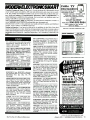
A Digital Storage Scope
For Just $200
"Watt Watcher"
Monitors Electric Use
Als
p, m
W
'Aw
Ct
S
E
..2....nos mown scolgorany
mwCZ NJ O
("ILA
0
U-1rv
-I m <
-1..0
Z r-
C
7C
.c.
m
ply For
rojects
Popular
apture Programs
og With Crystal Oscillators
Modern Electronics Computer Experimenter Lat (p. 12)
Schematics From Your PC (p. 35)
mon
limM
u.
4u
a.0
Compact Disc Technology and Computers
a Code Practice Oscillator
Melody Circuits and Other Interesting New iCs Latest Technical Books &
Literature ... more.
Plus: Build
-4GÑ
PHONES
NEC
.r
., If_ g)non
ST1ÑT/Stme-
(AIN
YOU EXPECT THE WORLD
FROM ICOM RECEIVERS
ICOM's IC -R71A and IC -R7000 are the
professional's choice for receiving inter-
national broadcasts, aircraft, marine,
business, emergency services, television,
and government bands. These people
demand the finest in communications
and so do you. ICOM puts the world at
your fingertips with the IC -R7000 252000MHz* and IC -R71A 0.1 -30MHz
commercial quality scanning receivers.
Incomparable Frequency Control.
Both the IC -R71A and IC -R7000 feature
direct frequency access via their
front keypad, main tuning dial, optional
infrared remote control and/or computer
interface adapter. Incredible Flexibility!
to 2000MHz* range. It includes all mode
operation low noise circuits plus outstanding sensitivity and selectivity. The
IC- R71A/R7000 combination is your
window to the world!
operator assistance! Additional features
include selectable scan speed pause
delays, wide/narrow FM reception and
high frequency stability.
Options.
IC- R7000: RC -12 remote
control, EX -310 voice synthesizer, CK -70
DC adapter, MB -12 mobile bracket.
IC -R71A: RC -11 remote control, EX -310
voice synthesizer, CK -70 DC adapter,
MB -12 mobile bracket, FL -32A 500Hz,
FL -63A 250Hz and FL -44A filters.
See these quality ICOM receivers
at your local authorized ICOM
dealer today.
The IC -R71A is a shortwave listener's
Spear teat ton. of the ICGkIIW guaranteed (rom 2 Ill EMH/
delight. Its 32 tunable memories
and I264C100MW. Novo, -rag, (rom IIMwLkIGMH,.
ICOM America. Inc.. 2380 -116th Ave. N.E. Bellevue. WA 98004
store frequency and mode information,
Customer Service Hotline (206) 454.7619
reprogrammable
Full Coverage, Maximum Performance. and they are single -button
3150 Premier Drive. Surte 126. Irving. TX 75063
1777 Phoenix Parkway. Suite 201, Atlanta. GA 30349
independent of VFO A or VFO B's
The superb IC -R71A is your key to worldICOM CANADA, A Division of ICOM America. Inc..
3071 tt5 Road, Und 9, Richmond, B.C. V6X 2T4 Canada
width,
Dual
an adjustable
operations!
wide SSB, CW, RTTY, AM and FM
it
slam smececale ns Ne s.gect cfalge *MVO npCe a
sq+eannv
egullms
RF
preamp,
panel
noise
blanker,
selectable
(optional) communications plus foreign
and selectable AGC combined with four
broadcasts in the 100kHz to30MHz range.
scan modes and all -mode squelch further
It features IF Notch, low noise mixer
enhance the IC- R71A's HF reception!
circuits and a 100db dynamic range. The
The IC -R7000 features 99 tunable
pacesetting IC -R7000 receives today's
memories
and six scanning modes. It
hot areas of interest, including aircraft,
scans
a band and loads memories
even
marine, public services, amateur, and
First in Communications
with
80
to
99
active frequencies without
satellite transmissions in the 25MHz
-
An
IO
e.ceem FCC
Ong
1.mrtmC
.
s
M
,
EDITORIAL STAFF
RN
El E
Art Salsberg
Editor -in -Chief
Alexander W. Burawa
Managing Editor
THE MAGAZINE FOR ELECTRONICS 6 COMPUTER ENTHUSIASTS
Dorothy Kehrwieder
JANUARY 1991
FEATURES
Production Manager
Emily Kreutz
Production
Elizabeth Ryan
Art Director
Barbara Terzo
Artist
Pat Le Blanc
Florence V. Martin
12
VOLUME 8, NUMBER
1
The Modern Electronics
Computer Experimenter Lab (Part
1)
Build a $200 Digital Storage Oscilloscope that
serves as the foundatio-i for a complete
experimenter's lab. By Martin Meyer
Linda Romanello
Phototypographers
Hal Keith
32
Illustrator
Photographer
Joe Desposito, Forrest Mims Ill,
Ted Needleman, Curt Phillips
Contributing Editors
BUSINESS STAFF
The "Watt Watcher"
Inductive -pickup meter monitors instant ac
power usage so you car more efficiently manage
your energy consump :ion. By Dennis P. Blum
Bruce Morgan
36
Publisher
Schematics for Your PC (Part 2)
1
Art Salsberg
52
General Manager
Wal
=rwo1
Associate Publisher
Dorothy Kehrwieder
TABLE OF
CONTENTS
A close look at popular schematic capture
programs. TJ Byers
Richard A. Ross
54
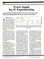
Power Supply for IC Experimenting
AC- operated dc power source can be used for
powering small, low -power circuits and projects.
Frank V. Fuzia
Controller
By Walter W. Schopp
Catherine Ross
FÏE
66
Circulation Director
Melissa Kehrwieder
54
Data Processing
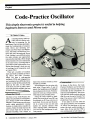
Code -Practice Oscillator
Helps beginners learn to send Morse code.
Carol Minervini
By Charles D. Rakes
Data Processing
Karen Nauth
Customer Service
COLUMNS
ADVERTISING SALES
ELECTRONIC ADVERTISING
Jonathan Kummer
(516) 681-2922
FAX: (516) 681 -2926
56
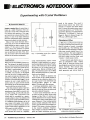
Electronics Notebook
Experimenting with Crystal Oscillators.
By Forrest M. Mims 111
COMPUTER ADVERTISING
Ken L. Wood
(407) 264-0545
66
72
PC Capers
Compact Disk Technology and Computers.
FAX: (407) 264 -0473
By Ted Needleman
Offices: 76 North Broadway, Hicksville, NY 1801. Telephone: (516) 681 -2922. FAX (516) 681 -2926. Modern
Electronics (ISSN 0748 -9889) is published monthly by
CQ Communications, Inc. Subscription prices (payable
in US Dollars only): Domestic-one year $18.97, two
years S36.00, three years $53.00; Canada /Mexico -one
year 521.00, two years S40.00, three years $59.00; Foreign -one year 523.00, two years 544.00, three years
$65.00. Foreign Air Mail -one year 576.00, two years
S150.00, three years S224.00.
U.S. Government Agencies: Subscriptions to Modern
Electronics are available to agencies of the United States
government, including military services, only on a cash
with order basis. Requests for quotations, bids, contracts, etc. will be refused and will not be returned or
1
processed.
Entire contents copyright 1991 by CQ Communications,
Inc. Modern Electronics or CQ Communications Inc. assumes no responsibility for unsolicited manuscripts. Allow six weeks for delivery of first issue and for change of
address. Printed in the United States of America.
Postmaster: Please send change of address notice to
Modern Electronics, 76 North Broadway, Hicksville, NY
11801.
CQ Communications, Inc. is publisher of CQ The Radio
Amateurs Journal, Popular Communications, Modern
Electronics, CQ Radio Amateur (Spanish CQ), and the
CQ Amateur Radio Buyer's Guides.
Say You Saw It In
Modern Electronics
72
Solid -State Devices
Serial Number Chip, Melody Makers, Silicon
Pressure Sensor and Free Selection Guide.
By Joseph Desposito
DEPARTMENTS
5
Editorial
By Art Salsberg
Letters
Modern Electronic News
8 New Products
75 Books & Literature
82 Advertisers Index
6
7
12
January 1991
/
MODERN ELECTRONICS
Sams Is Your Guide to Sate and Successful
Li Electrical Repair and Design
Compact Disc
Troubleshooting & Repair
Thom. Yon
Find Sams
Books At
These
Locations
California
Robert C. Brenner
Gregory R. Capelo
SANDY'S ELECTRONICS
C®p Pak CA
818. 3468353
TOWER BOOKS-SUNRISE
Cuts Nei_ CA
916.961 -7202
MAKVAC ELECTRONICS
01011161a CA
714-650.2001
VCR Troubleshooting &
HENRY RADIO
Lo. Angelo CA
213820-1234
Repair Guide
0- 672 -225077
$19 95 USA
Compact Disc
Troubleshooting
SAV-ON ELECTRONICS
Gallen Giove CA
714-530 -0533
&
Repair Guide
0- 672 -22521.2
S19 95 USA
CMOS Cookbook.
Second Edition
0- 672- 22459 -3
$18 95 USA
TTL Cookbook
0-672- 21035 -5
$16 95 USA
ITC ELECTROMCS
Lae Angelo CA
211388 -0621
OPAMP TECHNICAL BOOKS
Lo. Angelo CA
213-464-4322
ELECTRONICS CENTER
Oceanside CA
619-722- 5855
DOW RADIO ELECTRONICS
Oamd CA
805-486-6353
PANORAMA ELECTRONICS
Panama City CA
818- 894-22AB
TOWER BOOKS-WATT AVE
Saa.tta nto CA
916-4816600
STACEY'S BOOKSTORE
San Francisco CA
413-421 -4687
ACTIVE ELECTRONICS
Sm cs,. CA
408- 727-4530
Colorado
FISTELL'S ELECTRONICS
SUPPLY CO.
Denver CO
303-629-1312
GATEWAY ELECTRONICS
Dean CO
303 -458 -3440
PUEBLO WINTRONICS
Pueblo CO
719 -5421924
Florida
DOWNTOWN BOOK CENTER
If you need reference material or advice on designing circuitry, or even how to property clean
your VCR -tum to Sams. Sams' successful electronics titles cover a wide spectrum of
topics -and provide complete reference material for proper electronics use. Look for these
titles -and more -to guide you through all aspects of electronics!
SAMS
Mami FL
305377-9939
Ill/ill EDITORIAL Ill/Ill
Find Sams Books
At These Locations
Nevada
Georgia
SANDY'S ELECTRONICS
Las Vegas NV
OXFORD BOOK STORES
Adams GA
702-38 3 -8353
404- 262-3333
Illinois
B B
New York
ACTIVE ELECTRONICS
& W
Berwyn IL
Bohemia NY
516471 -5400
708 -749 -1710
TRI -STATE ELECTRONIC CORP.
Mount Raapect B.
800-445- 0896
MCGRAW-HILL BOOICSTO
Massachusetts
New York NY
212512-4100
BARILLARI BOOKS
Cambridge MA
617- 864 -2400
SALLNA ELECTRONICS
Syracuse NY
315 422-2336
MIL ELECTRONICS
Walthun MA
Ohio
617-891-6730
BOOK & CO.
ACTIVE ELECTRONICS
Dayton 011
Woburn MA
617-932-4616
513- 298.65400
WILKIE NEWS SOUTH
Maine
II &
R
Dayton OH
513-4 34 -8821
DISTRIBLTORS
Texas
Portland ME
207-713-2552
TAYLORS TECHNICAL
Michigan
Dallas TX
A I CAMPUS ELECTRONI -S
Am Arbor MI
313- 662 -0201
TEL VAN ELECTRONIC SUPPLY
Dearborn Ikights MI
313 -361.6080
ELECTRONIC PARTS CO.
BROWN BOOK SHOP
I louatm TX
ELECTRONIC PARTS
OUTLET
flotation TX
711784-0140
Washington
Detroit MI
ACTIVE ELECTRONICS
313 -893 -3228
S
011M ELECTRONICS
Ithaca NY
607 -273.8406
-F ELECTRONIC SUPPLY
Grand Rapids MI
INC.
T & W ELECTRONICS, INC
Grad Rapids MI
616241-3645
WARREN RADIO CO.
Bellevue WA
206881 -8191
Washington DC
REITER'S SCIENTIFIC
& PROFESSIONAL BOOKS
W aslungtm DC
800-537 -4314
Grad Rapids MI
616-456-5385
FULTON RADIO SUPPLY
Jackson MI
317- 784 -6106
Canada
ACTIVE COMPONENTS
Mississauga Ontario
WARREN RADIO CO.
416238-n23
Kalamazoo MI
ACTIVE COMPONENTS
616-381 -4133
FULTON RADIO SUPPLY
Loving MI
Mammal Quebec
514- 731.7441
313- 394 -5020
NOR WEST ELECTRONICS
Iwmu MI
313-261 -4551
WARREN RADIO CO.
Madison I kigMs MI
313- 588 -3377
REMCOR ELECTRONICS
Oak Pak MI
313-541 -3666
K 40 ELECTRONICS
Wawa MI
TIIE ELECTRONIC
CONNECTION
Westland MI
313. 595 -6655
Author's Guide
There are a lot of directories for writers that list a publication' article needs and requirements. I just finished filling
out some forms for one of them, in fact. Such questionnaires typically ask about the type of article purchased
from free -lance (not salaried staff) writers, policy on making assignments or working on speculation, the best way to
break into your publication, and so on.
Over the years, however, I've never come across a question relating to anything personal, such as religious beliefs,
politizal leanings, etc., though one can use write-in space
proviied on forms to indicate such policies. Doubtlessly,
there are some publications that do have such restrictions,
and there may be perfectly ethical reasons for this when an
editorial focus is especially narrow and requires a definite
slant. Electronics and computers do not fall within this
spectrum, of course.
That's why I was taken aback recently when one of our
favorite, admired writers, Forrest Mims, who writes Modem E ectronics's "Electronics Notebook" every month,
told me that Scientific American magazine refused to accept any more of his work as the writer of its "Amateur Scientist" column when it learned that he believes in the biblical concept of creation, rather than Darwin's theory of evolution. Forrest's work there (he wrote three columns before being cut off) concerned physical science experiments
and construction projects, not biology or philosophy, of
course.
It seems that Scientific American's editor feared that he
would be embarrassed if other people found out about
Forrest's beliefs and tried to exploit the fact that he was
writing for the publication. Now that's paranoid, at best, I
think, given the subject matter that Forrest writes about.
My view about this is, in a nutshell, what I told a Wall
Street Journal reporter, who quoted me in its newspaper as
follows: "His personal beliefs have nothing to do with the
work he does." Supporting my attitude, Forrest has indeed
been writing for me regularly for more than a dozen years
now. So have two other ME writers who share his private
beliefs. Clearly, it's simply not a consideration here for accepting or rejecting anyone's articles. Nor should it be otherwise elsewhere when the subject being written about has
no relation to another topic.
Would Scientific American have rejected writings from
William Shockley (co- inventor of the transistor and the
founder of a company that spawned California's "Silicon
Valley'') on solid -state technology because his controversial views on genetics may run counter to what they would
like it to be? I'm confident that this would not be the case.
Shame on you, Scientific American.
3
suers
January 1991
/
MODERN ELECTRONICS
/
5
IIiI LETTERS
Éxprésrs
340 E. FIRST ST.
DAYTON, OHIO 45402
_ER TIRE KIT
This popular
kit contains
170 of the
most popular
idler tires (10
each of 17
different
vow
-.a
..R.
size
money by having the right
save tuna!
tire in stock. Also included is a comprehensive cross reference listing over 80 manufacturers' assembly numbers and over 200
model numbers. (All tires are available
individually for reorder.)
$4995
VCR REPAIR PARTS KIT
With this
convenient
the same
day.
i
"Computer- Controlled AC Interface"
(November) really caught my eye and is
the type of material every computer hacker likes to experiment with. This is a good
project, but without a complete listing of
the BASIC control program, it is essentially useless. Could you please supply the
complete program?
Eugene P. Schmitt
Mequon, WI
You are correct. When we ran out the
disk file containing the BASIC control
program, the right side of those lines that
exceeded 66 characters truncated and left
the printout incomplete. Here is the program with all the information in it. -Ed.
Gremlins at Work
reading over my "Thermally Machine Project Boxes" in the November is-
kit you can
do most of
your VCR
repair jobs
vi)
ed parts for RCA, Hitachi,
Corr%
Fisher, Sanyo, Lloyds, Panasonic, Sony,
Sharp, JVC, and more. Over 45 parts in all.
(All parts are available individually for
reorder.)
$8995
10
20
30
40
50
60
CLEAR: CLOSE:
BYTES =" 0
LOCATE 1, 21:
LOCATE 2, 21:
LOCATE 3, 21:
LOCATE 10, 15:
1
IIA
sue, I noticed a couple of minor errors. In
the first column on page 20, line 17,
change "%-inch" to " /," -inch. In the Bill
of Materials, change the fuse specification to "fast- blow."
Adolph A. Mangieri
A Matter of Values
In the "Power On /Off I R Remote Controller" in the October issue, there is an
error in Fig. 2. The resistor and capacitor
values do not cause the circuit to oscillate
at 40 kHz, as the article states. The appropriate equation for this circuit is f =
1.44/[(RI + 2R2) x CI. Try the values
given in the article, and you will see that
one or more of them is incorrect.
Kevin C. Carpenter
Colchester, VT
The value of the capacitor should be
0.005 microfarad. While this won't yield
an exact 40 kHz, the transmit frequency
will be close enough for purposes of the
project. To get much closer to the mark
with this value, you would have to change
the value of R4 to 2,500 ohms. -Ed.
ln
vow ,MPAMR PARTS
I.
KEY OFF: CLS: DEC = 0: OUT 888, DEC
0
0"
0
0
0
0
0
PRINT " ZDDDDDDDDDDDDDDDDDDDDDDDDDDDDDD7"
PRINT "3 PARALLEL INTERFACE PROGRAM 3"
PRINT "@ DDDDDDDDDDDDDODDDDDDDDDDDDDDDDY"
3
5
4
7
6
PRINT "BIT NUMBER
2
0
15: PRINT " DDDDDDDDDDDDDDEDDDEDDDEDDDEDDDEDDDE
DDDEDDD4
3
3
3
3
3
3
3
80 LOCATE 12, 29: PRINT "3
An
A
A
A
A
A
A
A
90 LOCATE 13, 29: PRINT
VALUE
"; BYTES
100 LOCATE 14, 15: PRINT
GEORGE F. STOCKMAN, IV,
110 LOCATE 21, 16: PRINT "COPYRIGHT,
1989"
120 DELAY = TIMER + 5: WHILE DELAY > TIMER: WEND
130 LOCATE 21, 16: PRINT STRINGS(41, 32)
140 LOCATE 21, 11: PRINT "BIT NUMBER TO TOGGLE / (CR] TO RESET /
(ESC] TO END"
150 AS = INKEYS: IF AS _ nn THEN 150
160 IF AS = "0" THEN 240 ELSE IP AS = "1" THEN 260 ELSE IF AS _
"2" THEN 280
170 IF AS = "3" THEN 300 ELSE IF AS = "4" THEN 320 ELSE IP AS =
"5" THEN 340
180 IF AS = "6" THEN 360 ELSE IF AS _ "7" THEN 380
190 IF AS <> CHR$(13) THEN 230
on
0
0
0
0
0
0
200 BYTES =" 0
210 DEC = 0: BITO = 0: BIT1 = 0: BIT2 = 0: BITS = 0
0:
GOTO 430
BITT
=
220 BIT4 = 0: BITS = 0: BITE = 0:
230 IP AS = CHR$(27) THEN CLS: SYSTEM ELSE BEEP: GOTO 150
240 IF BITO = 0 THEN BITO = 1: DEC = DEC + 1 ELSE BITO = 0: DEC =
DEC - 1
250 GOTO 390
260 IF BIT1 = 0 THEN BIT1 = 1: DEC = DEC + 2 ELSE BIT1 = 0: DEC =
DEC - 2
270 GOTO 390
280 IF BIT2 = 0 THEN BIT2 = 1: DEC = DEC + 4 ELSE BIT2 = 0: DEC =
DEC - 4
290 GOTO 390
300 IF BITS = 0 THEN BITS = 1: DEC = DEC + 8 ELSE BITS = 0: DEC =
DEC - e
310 GOTO 390
320 IF BIT4 = 0 THEN BIT4 = 1: DEC = DEC + 16 ELSE BIT4 = 0: DEC
= DEC - 16
330 GOTO 390
340 IF BITS = 0 THEN BITS = 1: DEC = DEC + 32 ELSE BITS = 0: DEC
= DEC - 32
350 GOTO 390
360 IF BITE = 0 THEN BITE = 1: DEC = DEC + 64 ELSE BIT6 = 0: DEC
= DEC - 64
370 GOTO 390
380 IF BITT = 0 THEN BIT? = 1: DEC = DEC + 128 ELSE BIT7 = 0: DEC
= DEC - 128
" + STR$(BIT6) +
390 BYTES = nn: BYTES = BYTE$ + STRS(BIT7) + "
70 LOCATE 11,
'
VCR SPRING ASSMT
A wide
assortment
of springs
used i
many n
brand V
Clutch sings, idler springs, tension
springs, etc. 11 tension springs and 5
pressure springs.
$150
#MM- 430 -300
VCR WASHER ASSMT
A wide
assortment
of plastic
washer
used in
clutch as mb1ies and idlers. 150 pieces,
split ring and regular.
$590
CALL
TOLL FREE
It
FREE CATALOG
1- 800 -338 -0531
400
410
420
430
el
BYTES = BYTES
BYTES = BYTES
BYTES = BYTES
OUT 888, DEC:
+ STR$(BITS) + "
+ STRS(BIT3) + "
+ STRS(BIT1) + "
LOCATE 14,
28:
" +
"
"
STR$(BIT4) +
+ STRS(BIT2)
+ STR$(BITO)
+ "
"
"
+ "
"
"
PRINT BYTE$;: GOTO 150
CIRCLE NO. SI ON FREE INFORMATION CARD
6
/
MODERN ELECTRONICS
/
January 1991
Say You Saw It In
Modern Electronics
III1IIMODERN ELECTRONICS NEWS//fill
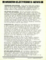
COMPUTERIZED CHESS TRAINING. World chess champ Garry {asparov
"trains" with an Atari MEGA -2 computer. He and his coach store
chess moves made by tournament players in a database program,
which is run to analyze strengths and weaknesses of other
players. Prior to this, trainers had to manually clip and sort
through articles on matches played throughout the world.
NEW RESEARCH DEVELOPMENTS. Bellcore researchers developed a
unique, low -cost prototype device that detects fires involving
polyvinyl chloride (PVC) before there's smoke or even heat. When
PVC, which is a common cable and wire insulation material,
overheats or burns it produces the extremely corrosive hydrogen
chloride gas that can destroy electronic equipment even several
floors away. The gas is emitted before PVC burning takes place.
The new device uses an inexpensive quartz crystal coated with
zinc that's set to vibrate at a certain frequency. The zinc metal
corrodes when hydrogen chloride gas hits it, forming zinc
chloride which rapidly absorbs water from the air. This causes
the quartz crystal to change its vibration frequency, which sets
off an alarm before flame or smoke occurs.
BRIGHT WHITE LED. Ledtronics's (Torrance, CA) new WhiteLite LED
is said to be the industry's first mu =ti -chip white LED 100%
brighter than present amber -yellow technology. It's intended to
be an incandescent lamp replacement for the world' most popular
color and can be used to re -lamp pushbuttons, backlights, and
control -panel indicators. It's an electrical and mechanical
duplicate of the incandescent lamp it replaces and will not cause
heat damage to lenses, which might be colored red, orange, among
others. LEDs can be expected to operate at least 100,000 hours
compared to an approximate 4000 hours for incandescents, which
makes them very cost -effective. In 1000 quantities, they're
priced $2 to $3 each, depending on base style ordered.
SECURITY ROBOTS. Cybermotion Inc.'s (Roanoke, VA)
new mobile security robot is based on the company's Navmaster
mobile robot with the addition of a special Security Patrol
Instrumentation package that adds the capability of monitoring
large areas for fire, intrusion and air quality.
The robot navigates primarily through use of a digital sonar
system that's programmed by drawing routes onto a CAD drawing of
the facility. A Dispatcher program uses this data to generate
random patrol programs that are transmitted to the robot via
radio. The operator can also drive the robot remotely to
investigate special situations. The robot's base contains sensors
for temperature, smoke, gas and relative humidity, as well as an
interface for an option camera system. A rotating head has a
passive infrared scanning imager, a K -Band presence radar and a
UV detectors. The radar can detect objects through walls.
APPLIANCE REMOTE CONTROLLERS. NEC Electronics (Mountain View,
CA) introduced three low -voltage, low- current controllers for
remote control applications in household appliances and air
conditioners. All feature a carrier generator circuit for
infrared remote control. They operate on a voltage range of 2V to
6V, enabling operation with two batteries.
Say You Saw It In Modern Electronics
January 1991
/
MODERN ELECTRONICS
/
7
1111//I
NEW
PRLTS
i
For more information on products
described, please circle the appropriate number on the Free Information
Card bound into this issue or write to
the manufacturer.
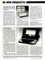
Computerized Bridge Game
Pro Bridge 500 from Saitek Industries Ltd. (Torrance, CA) is a new
computerized bridge game that is
claimed to challenge serious club
players and has integrated coaching
features for beginners. It plays both
rubber and duplicate bridge. You can
select up to five major bidding descriptions: Acol, American 5 Card
major, French 5 Card major, American Standard and Precision club
with 11 bidding conventions. If players choose to play against different
conventions, they can set the
-
hands on view to see how they interact as the game progresses.
Laptop design makes it easy to use
Pro Bridge 500 at home and while
traveling. When opened for play, the
top displays four screens: one
16- character LCD screen with menu
options and two player positions,
two more screens for player positions
and to keep score in a layout that
makes it easy to follow the game. The
top panel folds flat and snaps shut
when the game is over. Pro Bridge
500 measures 9 inches square by
inches deep. $399.
1
North /South and East /West positions separately.
Built -in coaching features help develop skills and expertise for all player levels. Coaching can give hints,
suggest which card to play and allow
take -back of a bid or card. It also permits players to review a game with all
CIRCLE NO. 2 ON FREE INFORMATION CARD
Triple Power Supply
Global Specialties' Model 1310 dc
bench -top power supply has three independent outputs: 5 volts at am1
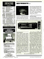
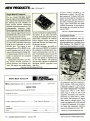
Portable Computer
The new 6-pound (with battery) Tandy 1500 HD notebook PC comes
with both standard floppy and hard disk drives. Built around the NEC V20 microprocessor operating at 10
MHz and 0 wait state, the computer
features 640K of user RAM (expandable to 1.64 M); 3.5 -inch, 1.44MB
floppy drive; 20MB hard drive with
23 -ms access time; high- definition
blue -on -white LCD screen with 640
x 200 -pixel resolution; MS-DOS
3.3; DeskMate® personal productivity software; and LIM 4.0 expanded
memory driver.
A rechargeable Ni -Cd battery is
said to provide more than 3.5 hours
of computing time. A new "Power
View" LED system monitors battery
status. This indicator and the Power
indicator are located on the top -right
of the computer case for clear visibility without lifting the display. The
Power switch is also located under
the display to prevent accidental battery drain.
The battery weighs just 12 ounces
and recharges in only 4 hours with
8
/
MODERN ELECTRONICS
/
the computer off (8 hours with the
computer on). An 8 -ounce ac adapter /charger is supplied. The 84 -key
Tandy Key- SwitchTM keyboard allows you to interchange the CTRL and
CAPS LOCK key caps and functions to
provide a standard typewriter layout.
Included with the full -size keyboard
are 12 function keys and an embedded numeric keypad to provide 101-
January 1991
key emulation.
Other features include: an internal
modem, a 25 -pin parallel -port connector and a 9 -pin DB -9 RS -232C serial -port connector. Options include
a 1MB user -installable memory upgrade ($400); 2,400-baud internal
modem ($200); spare battery ($100);
and choice of carrying cases. $1,999.
CIRCLE NO. 6ON FREE INFORMATION CARD
Say You Saw It In Modern Electronics
Which symbol
politan areas. The new transmission
system is claimed to deliver bright,
bold pictures and clear sound.
represents a
variable inductor?
CIRCLE NO. 40N FREE INFORMATION CARD
No- Contact Voltage Sensor
A non -contact voltage detector has
been announced by A.W. Sperry.
pere and two variable 1.3 to 20 volts
at 250 mA each. It features series and
parallel operation and digital current
and voltage metering via a three -digit
-inch tall LED numeric display.
Display accuracy is rated at ± 0.5 %,
± digit. All supplies are current
limited and short -circuit protected.
The Model VH -601A Volt Sensor is
designed to detect 100 to 600 volts ac
with respect to ground by simply
What is the principle disadvantage
of neon lights?
What are out -of -phase signals?
1
Heath Video Courses
speed your learning curve!
CIRCLE NO. 3 ON FREE INFORMATION CARD
Learn basic electronics at home at your own
pace with four, 60- minute video tapes. Know
Video Rebroadcaster
the variable inductor symbol. Recognize a PN
junction. Understand oscillator fundamentals.
Clearly SEE what most basic electronic books
can only describe.
Midland International's Model 72400 Pow -R -Max Video Commander
rebroadcasts programs from VCRs
or any other source that has an audio/
video jack to one or more TV receiver
locations up to 100 feet away. The
system is made up of a small transmitter and one or more receivers. A
DC Ei.ECTRONCS. Covers electron movement to troubleshooting and repairing a
simple electronic circuit. EV- 3101 -A.
AC ELECTRONICS. Follow -up to DC Electronics. Covers the principles of AC, voltage and
electrical measurement. Includes motors,
generators and test instrument meter
movements. EV- 3102 -A.
grasping the instrument in yo Jr hand
and placing the tip near a live wire. If
the wire is, indeed, "live," the
VH -601A gives both audible and
visual indications. The 1.4 -oz. device
requires two AA cells for operation.
CIRCLE NO.5 ON FREE. INFORMATION CARD
CD Lens Cleaner
separate receiver is required by each
TV receiver that is to pick up the rebroadcast signal. To install the system, you simply plug the transmitter
into the desired video program
source and a receiver into each TV receiver that is to pick up the signal.
The 72 -400 uses a different broadcasting system than previous systems. It eliminates the need for fine
tuning systems and has special filtering to prevent interference in metro-
3611COND JCTORS. Complete the DC/AC
videos and you're ready to learn how semiconductor devices are made, plus the
principles of discrete devices, integrated
circuits & optoelectronic devices. EV- 3103 -A.
ELECTRONIC CMCUTS. Complete the basic
course with amplifier configurations, biasing,
coupling, audio amplifiers, closed-loop vs.
open -loop operation and more. EV- 3104 -A.
An activity-filled workbook and explanation
of how to solve each problem comes with
video
each tape so you learn three ways
workbook and hands-or/
-
Order today)
The Audio -Technica Compact Disc
player lens cleaner uses an eight -brush
wet/dry system to completely remove
dust, oil and other contaminants
from laser lenses. The No. AT6078
accessory is said to maintain optimum laser performance, reduce playback errors and eliminate excessive
error correction.
Eight specially positioned brushes
mounted on a Compact Disc wash
and whisk away contaminates and
Call Toll tree,
24 -hours a day.
1-800 -253-0570.
We accept VISA,
MasterCard, American
Express and Heath Revolving
Charge card. Use Order Code 601 -051
eathi
Benton Harbor, MI
Call for a FREE catalog 1- 800- 44HEATH.
Price does not include
shipping and handling,
or applicable sales tax.
01990, Heath Company
Subsidiary of Bull Data Systems, Inc.
C'IRC'LE NO. I ON FREE INFORMATION CARD
Say You Saw It In
Modern Electronics
January 1991
/
MODERN ELECTRONICS
/
9
AMAZING
NEW PRODUCTS
SCIENTIFIC & ELECTRONIC
PRODUCTS
6RAI
ANTI GRAVITY GENERATOR
40 WATT BURNING CUTTING LASER
HI POWER PULSED DRILLING LASER
I MILLION VOLT TESLA COIL
HI VELOCITY COIL GUN
LASER LIGHT SHOW 3 METHODS
ELECTRONIC HYPNOTISM TECHNIQUES
LOWER POWERED COIL GUN LAUNCHER
JACOB LADDER 3 MODELS
c15ii LC7
RUM
(í
s.
2
a
a:
BTC5
MCP1
MI
EH1
N
EML1
Z
JL3
g
SEE IN THE DARK
LEVITATION DEVICE
SDS
xL LEVI
i
NI07K
P65K
LHC2K
HOK1K
ó
LMUBK
BTC3K
E
I092K
Ñ
$10 00
$34.50
$49.50
$34.50
$49.50
$44.50
$44.50
2.5 MW HAND-HELD VISIBLE LASER GUN $249.50
.$249.50
250,000 VOLT TABLE TOP TESLA COIL.
ithout wires .$129.95
ION RAY GUN. project energy
PFS1K
i
<
TELEKNETIC ENHNCER /ELECTRIC MAN _.$79.50
TKEIK
$49 50
VWPM7K 3 MILE AUTO TELEPHONE TRANSMITTER
W
LIST10
IP670
m
171110
ASSEMBLED IN OUR LABS
INFINITY XMTR Listen in via phone lines... $199.50
INVIS. PAIN FIELD BLAST WAVE GEN
$74.50
a
CIRCLE NO.
dry the lens. To perform a cleaning
operation, you apply a single drop of
laser lens cleaning fluid to the innermost brush, after which you place the
7
ON FREE INFORMATION CARD
I/O Port System
A professional AppleTop Bus ported
control system for all models of Mac-
100.000 VOLT INTIMIDATOR UP TO 20'
$99.50
AUTO. TELEPHONE RECORDING DEVICE
$24.50
PHASOR SONIC BLAST WAVE PISTOL
$89.50
ALL NEW 26' VIVID COLORED NEON STICK $74.50
.5 TO 1MW VIS. RED HeNe LASER GUN
$199.50
100.000 WATT BLASTER DEFENSE WAND. .$89.50
TAT30
PSP40
DNE10
L6U20
y
N
onds, at which point the player automatically stops. Audio -Technica
recommends that it be done at least
once a month, more frequently if
your player is subjected to a lot of
cigarette smoke. $24.95.
3 MILE FM VOICE TRANSMITTER
HAND CONTROLLED PLASMA FIRE SABER
HI FLUX NEGATIVE ION GENERATOR
PLASMA LIGHTNING GLOBE
VISIBLE SIMULATED 3 COLOR LASER
HOMING /TRACKING BEEPER TRANSMITTER
FMV1K
z
disc in the drawer of the player brush side down and activate play. Cleaning is accomplished in about 10 sec-
$10.00
$20.00
$20.00
$20.00
$15.00
$20.00
$8.00
$8.00
$10.00
$10.00
.
BLS10
EASY ORDERING PROCEDURE - TOLL FREE 1- 800 -221 -1705
or 24 HRS ON 1. 603.673 -4730 or FAX IT TO 1-603-672-5406
VISA, MC, CHECK, MO IN US FUNDS. INCLUDE 10% SHIPPING.
ORDERS
$100.00 8
UP ONLY ADD $10.00. CATALOG
FREE WITH ORDER.
$1.00 OR
INFORMATION UNLIMITED
P
0 Box 716
DEPT MER AMHERST
NH 03031
LEARN TO
CLEAN /MAINTAIN /REPAIR
FAX MACHINES
Stereo Receiver
HUGE fflY UNTAPPED MARKET!
million Fax machines in homes/
offices -predictions are for ev r25million
Over it
by 1992!
f'
Work from your home /van
OW Home study program gets you started servicing
fax machines in 2 weeks!
D3' Ile special tools /equipment needed
1
Earn additional profits selling fax supplies!
- therefore. you can
get good SS for the repair
Average Fax machine requires professional service
Fax machines are not cheap
every
18
months
Home study training program includes full instruc-
tions on EVERY ASPECT of Fax maintenance /repair
FULL COVERAGE of how to set up your home -based
service business
Onkyo's Model TX -866 AM /FMstereo receiver offers 88 watts per
channel into 8 ohms (185 watts per
channel into 2 ohms)-plus room -toroom remote control. An exclusive
APR (Automatic Precision Reception) system continuously monitors
the FM signal and adjusts critical
tuner mode, sensitivity and high -frequency blend to provide optimum
performance. Direct Access Tuning,
punching in a desired station frequency from a front -panel numeric
keypad, and Classified Memory Preset permit each of the tuner's 40 AM/
FM station presets to be assigned to
any of six classes. These classes can
be assigned by type of music programming or according to any other
scheme. Pressing a button gives a
brief sample of each station in the
selected class.
FREE DETAILS
CALL 1 -800- 537 -0589
Seven inputs are available, with
audio /video switching and dubbing
facilities that enable them to serve as
the core of a sophisticated A/V system. Standard rotary bass and treble
controls are augmented by a slide type Selective Tone /Loudness control that progressively boosts verylow and very -high frequencies in balanced proportion to maintain a tonal
balance when listening at low volume.
Other features include a sleep timer; Onkyo's slide control in the Dynamic Bass Extender circuit that permits adjustment for fuller low -frequency reproduction; and a Stereo
Image Expander. A large fluorescent
display shows tuned frequency,
memory preset selected, class selected and bargraph tuning. Lighted
legends indicate which functions are
active. The IR remote transmitter duplicates most of the control functions
available at the receiver. $480.
CIRCL.F, NO. 9 ON FREE INFORMATION CARD
Or Write To: VleJo Publications, Inc.
5329 Fountain Ave., Dept. ME/FX
Los Angeles, CA 90029
CIRCLE NO. 15 ON FREE INFORMATION CARD
10
/ MODERN ELECTRONICS /
January 1991
Say You Saw It In Modern Electronics
intosh computers is available from
Ansan Industries (Arlington Heights,
IL). The I/O Port System is said to be
ideal for automating most electrically operated devices in the home. It
can monitor fire and security systems, operate automatic sprinklers,
program lights to turn on and off, etc.
All that is needed to accomplish
control is a main control system
module called a Bridge. The Bridge
reads, monitors, controls and records signals using analog and digital
input /output channels. It can be
programmed to control any device in
any time frame desired. Even if the
frequency- ratio, time -interval and
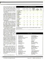
totalize measurement functions. Its
temperature- compensated timebase
is designed to provide reliable performance in changing ambient -temperature environments.
The CDC250 can be used as a
stand -alone calibration tool or as a
rack -and -stack component in a
bench setup. Except for a rotary trig -
Hz to 175 MHz at input levels ranging from 20 mV to 24 volts peak. It
also provides period measurements,
78)
HITACHI PRODUCTS
AT DISCOUNT PRICES
RaI
ELENCO
-Tim.
RSOs
,7,,,ft%
(Continued on page
G--
&
Compact Series Scopes
Storage OscIllOSCOpes) From HITACHI NF
&
The RSO
IM new solution
ns
-
Ite
View, A_aulre, Test. Transfer end DOCument Your Waveform Data
InHOduClOry ß1C4
4 CnOnnel, IOOMSra Model
teens, 125YS.s on 4 CarrelsSr,Jaepusfyl 1001100 ere r tat 2k. . 7,,,e 1wr4,^ VC-61 45 f 4.695 00
_
Dee,° Seam
lgMw9nt 1134.1
-
p
7rne Sens
-
,
3
Compact. Full Feature Models
ame cn 25*
40MSS, 100MNt,
a
$
3.049.00
VC -6025
S
2.295 00
This safes prOydes many new functions such as CRT
ton
VC -6024
S
2Cr
VC -6023
S
2,049.00
1.749.00
Readout, Cursor measurements (V. 108511065/665).
Frequency Dr IV. 10651. Sermon' A,noran9lrlg and
Trigger Lock using a 6Inch CRT You doni feel me
2511
2.0
Snows
low Cost, nigh Value Models
201151, SOMHO. 2kw
20MSs, 201100,
tee .
compactness
RSOs from Head feature mrh fundons a roll mod., avarag rg savor memory. .nmtn.q.°narpolaon. praupger.y,
rM.c.. and RS 2DC rntarr, a Won ma Wm od or analog m mm power of dpnal
wr.or m.esur.me..lHx
t
11.
V-212
"roe
- -
Dc
10
cn.,,,w, V.s2s CRT Readout. Cursor Mom
0.523 Deemed Sweep
turned off or power
fails, the Bridge performs many of its
functions.
If more channels are needed to perform household functions, a Digital
expander can be added. Up to eight
bridges and 16 expanders can be connected to a single computer without
using up any slots or SCSI ports.
The easy -to- install system attaches
to a Macintosh via standard keyboard cables included in the package.
It can easily be adapted to monitor
and control custom applications using the software provided. Modules
for writing your own software are
also included, and telephone support
is available. About $500.
CIRCLE NO.
14 ON
20MHz Elenco Oscilloscope
1150
Ceepn
w lame
ley
'
OSMH2. Is. 1131
51995
R2 IOOMFO, 1., Ms 52395
Tv Sync
")
'-
1aeRr T,.
°x.5 Operen
2 Ast
D.ls,M Trgmp Sue
Incbdea 2 P4 Plebe
-,1
1
Askew sebda peers.
Iehemahcs. operators manual. and 3 year (2 yrs for eenco scopes) world lode warranty on parts
Hitachi sages. CM or eels for complete Spent cdt,ons on these and many other tre 0ScIIOSCOpes
10
COMPLETE LINE
MULTIMETERS
Models
21F
63
23F
85
27F
27F
87
DC
Arrur,
and
1* * i1
St
Ñhob.r,pM.
N,.m
W b tYHi
.
AM or FM
Pepeea,
....
hewed
Ms,
four
1SVN
;
1A
r I.
Comrns Si
dasnd Mrurx la ,bap pwwwtu
Feew shad arcun prdgan. et .re..
#.
seem.
Digital
SG -9500
059.y
7-
a1T41111
-
a
am
.I
Case
Digital Triple Power Supply
1
4
-
Furl,
r.r..
,eouw.d Sew c.cun
s_ con-or
I
p'
_
Fee
1(17575
XP-765
$ 249
pmvu to
GF -6016
re
to
5Va
SA
-
/
erin
12V
7A
without muter.
INCLUDES All Pala,
ru
SUM
Function Generator
.'i
with Freq. Colder
.44
Sne 5 u 1. T
Rue, Comp 2 to2MW
Frp
Co,. I. 10a111í
w
am arum
M.
lrdeo
WE WILL NOT BE UNDERSOLD!
UPS Shipping: 4sStates5 °.
($10 Max) IL Res., 7% Tax
(
o. Mou area.
r
1.d.
e .ó.laM.amr.d.
ROBOTICS RR FOR MOVE (MM 1010) 871.e1
F9015 wInWN Frp. Meter 1179
C & S SALES INC.
1245 Rosewood. Deerfield, II 60015
1600) 292 -7711 57080 541.0710
1R('5 E NO 35 ON FREE
mew
RAF
0116 r/aorob pp mewl are eve ere
nee essmeaea
par
ee
a peewee mayor,
eeraE eCe
deer»
me. m,Pulw wars Rues yore own .were
and Mee Me a e0, ayls.d and d.r.y It, .lode ..1..r
w
seueeese
b
me...
C
MI urea.
/ROM ednmaay.noap,ma
eeriey,bwenee.
more
I.e.9.e.IMF PC Vol sae
Serene.,
...
$249
.wee PWe
xe -se0 with Angles Motes 1175
LCD
/0,
OM lo IOWD
5
.o.d
-
$18.95
o20v
22av
*dá
LEAkN TO BUILD AND PROGRAM
COMPUTERS WITH THIS KIP
A.rmdy Ord La.. Mons.
Model
XP -S80
$59.95
/9620
pr. nold
'TM's
M
5000
9Fur,ns45
Mencrr ea
f^9ß
see
yay yp SV'e
Quad Power Supply
aílrlBba
-
Clayprr.I.Otl
$69.95
s
Decode Mod
men or
AC Cana1R WMr
!)De4r::
wte ran.
M
f29.95
DCAc
Ansel
output
Autoranging DMM
M 110CF
-0OOF
ION,
or
PF
and 1SOMNt built -In Counter 12x9
Temperature Probe
fZ75
smf
129
RFFrw 100 aLLYw
e
114
SG-200
i0i0paaaa
. 012W
As Ymswon
end AV et
Tenpin
Ip420oIe
R
SG -9000
30V
TO
Color Convergence Generator 10MHz Oscilloscope
n
.
Kit $45
21p15y.la.
Cp
nd Generators
Wide Band
Assembled MS
$M
$1251
cols 1.120115l
sxaesaa,
Dee we
to
Meta
f
rp.20,000eld
Triple Power Supply XP -620
$28.95
roxM.
a
CR
D
$58,95
5 p.
a
Rasmanns to zDOODU
8600
lasoo
SPECIAL PRICING
oc . Dc uoMo.
Dim Lopa
Goes
MA. res.
°l nctbn Generator
n
=.
., itasistrour
Fr.. Cosnlo
mth
8060A
B060A
75
8062A
77F
More
CALL FOR
Soldering
4J
$135
OS,
of
CM -1550
CM -365
1....',.:
M -7000
OF
FLUKE
any aaessones available for all
labor
Function Digital
Mu$Umeter
DIge MFtenerer
a
Cy
B
o
Sweeney
acv A,xrrrsm VW..
f'r'
I
-ea.
2p Press
WE
$1,695
$2,045
$2,295
$2,775
MO-1252
p.I
x.y OpFlien
$1,345
$1,425
Mee seenamAcat
SCOPE PROBES
.rCRT
$1,195
Elenco 35MHz Dual Trace
Good to 50MHz
Ma l
Universal Counter
Say You Saw It In Modern Electronics
se's
with purchase of
ANY SCOPE
$375
V
-1065
V-1100A
FREE DMM
MO -1261
FREE INFORMATION CARD
Tektronix's new Model CDC250 universal counter is designed for use applications where multiple measurement capabilities are needed. The
dual -channel instrument counts signal frequency of sine, square and triangle waveforms over a range from 5
V.522 ease Mac.
V422 40We Dual Tram 5715
is
V -1065
51.025
penOrmdnCe and Operasen
Of
100MHz Quad Trace wCursor
150MHz Quad Trace w'Cursor
V -1060
$945
terms
V
V -665
DC b SOMHz, 2-Channel, DC offset
function, Alternate magnifier function
In
60MHz Dual Trace
60MHz Dual Trace w/Cursor
100MHz Dual Trace
100MHz Dual Trace wCursor
100MHz Quad Trace w/Cursor
V -660
Hitachi Portable Scopes
$435
oseN,
Dual
computer
-1065
MOON
VC 6045
5
,
20MS4, 50M02, 2kw
Y wan.,,
15 Day Money Back Guarantee
2
Year Warranty
E. FOR FREE CATALOG
VI R1 -I
INFORMATION ( ARD
January 1991
/
MODERN ELECTRONICS
/
11
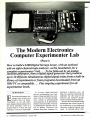
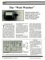
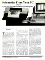
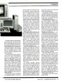
The Modern Electronics
Computer Experimenter Lab
(Part 1)
How to build a $200 Digital Storage Scope, with an optional
add-on eight -channel logic analyzer, as the foundation for a
complete experimenter's lab ... To be followed by an analog
function generator, then a digital signal generator that produces
up to 20 different simultaneous digital signal trains from a built -in
library of experiments or from programs downloaded from an
IBM PC or compatible ... Plus ongoing experiments for all
experimenter levels.
By
Martin Meyer
Electronics and computer tech-
nologies have become more
complex than ever before.
Nevertheless, we can still experiment, design products and learn how
the newest technology works on a
personal basis if we have the right
equipment. Even on a kitchen table!
12
/
As we know, digital electronics
and the microprocessor have combined to change and add extra excitement to the art of product development, whether as general -purpose
microcomputers or as dedicated -application microcontrollers. The project presented here initiates a new series by Modern Electronics-The
Modern Electronics Computer Ex-
MODERN ELECTRONICS / January 1991
perimenter Laboratory -that will
help you to quickly understand and
implement the wide range of new
electronic and computer developments constantly being introduced.
We start here with a digital storage
oscilloscope that will serve as part of
the underfooting of an exhilarating
electronics/computer learning experience. An optional add -on eight-
Say You Saw It In Modern Electronics
WilliElECtl7DERNRomcs
Project
channel logic analyzer is also available to expand the utility of the Experimenter Lab (see the Note at the
end of the Parts List). An analog
function generator and a digital signal generator in upcoming issues will
round out the laboratory, preparing
you for a host of new- technology
learning experiences.
A stimulating aspect of this project
is that we can use the scope to look inside the scope itself and see how most
of the components used actually
function. Seeing is believing
and
doing helps the learning process. Before describing how the scope you
will build works, let us discuss what
that instrument can do, cannot do,
and how it compares to commercially
available scopes.
...
The DSO Project
ISi
1
Say You Saw It In Modern Electronics
DIS1
LCD.pATA
I_lf:l
MLi:Tf4B191
SCANSTART
ACJDRIVE
DATAIATCH
líi1:>l74
1ril(1141[41111
DATA_CLOCK
N/C
.SV
GND
1T_1(:Z4SI4M
VCC O
VDDO
LM24013W
LCO DISPLAY
1S
CONTRAST
LCD
R4
CONTRAST
DK
INITIALIZE THE DISPLAY TO RON ONE
SCAN START
DATA CLOCK
240 CLOCK PULSES PER RON
240 DATA SIGNALS (HIGH OR LOW)
DATA IS CLOCKED IN DURING FALLING EDGE OF
DATA CLOCK SIGNAL
LCD DATA
ENTIRE ROW (240 DOTS) LATCHED IN WITH THIS PULSE
DATA LATCH
AC DRIVE
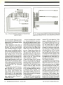
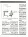
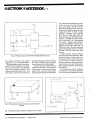
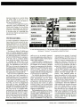
This project is known as a Digital
Storage Oscilloscope, also known as
a DSO. This means that input signals
are converted by an analog -to-digital
(A /D) converter to a digital signal
and then displayed on a screen. A
standard analog scope uses the input
to move a beam on the screen to produce this display. The major advantage of a DSO is that an event can be
saved or frozen on the scope screen,
giving the user time to evaluate the
results of an experiment. In contrast,
the display of an ordinary analog
scope is lost the instant after the
event occurs.
There are tradeoffs, naturally. A
disadvantage of DSO scopes is that
bandwidth may be somewhat less
than some of the more -expensive analog scopes. The DSO to be described
is capable of sampling the input 20
million times per second, which is
more than adequate for experiments
we will be conducting. Its vertical
sensitivity ranges from 10 mV to 5 V
per division (50 V per division if a
10:1 probe is used).
Our DSO's horizontal timebase is
adjustable in 21 steps from As to 5
seconds per division. The display used
January, 1991
ALTERNATES PRLARITY EACH FRAME (64 ROWS)
t
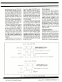
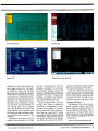
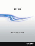
Fig.
1.
Circuit details of the liquid-crystal display section.
standard liquid- crystal snit composed of 64 dots vertically and 240
dots horizontally. Accord:r gly, this
resolution results in a display that is
not as smooth or as bright as that of
an analog scope. For example, noise
looks a bit odd because it produces
little steps in the display, but this is
easy to get used to. (In the Logic Analyzer mode, the display is smooth
because signals are either in a high or
low state.) Nevertheless, it is satisfactory for our purposes.
Most scopes do not include Logic
Analyzer inputs. We decided to add
this feature because the ability to
view signals simultaneously is invaluable in learning how digital circuits
work. Understanding microprocessor timing diagrams becomes simple
when you can view the bus and control signals at the same time!
Learning how to design and apply
digital or computer circuits is not as
difficult as many people imagine.
The following is a breakdown of
is a
some of the steps in the learning
process:
how to use binary
numbers
(2) Learn how basic logic
components work:
Gates and Buffers
Latches and Flip -Flops
Counters and Registers
Multiplexers and Decoders
(3) Learn how a microprocessor
works:
CPU and Support Chips
I/O and Timer Ports
Communication Chips
Various RAM and ROM
Chips
Simple Assembly- Language
Programming
(1) Study
Understanding these principles by
physically making them happen will
be enjoyable and can be profitable. A
scope, logic analyzer and analog/
digital signal generators are particu-
January 1991
/
MODERN ELECTRONICS
/
13
PARTS LIST
Semiconductors
CR 1-20-MHz crystal oscillator
D1 thru D7-1N4002 diode
U 1 ,U 19,U21-74HC373
U2-74HC 165
U3-74HC 138
U4-74HC 139
U5-74HC04
U6,U22,U31-74HC00
U7-80085A
U8-6264
U9-81055-5
U10-27C64 or 27C256
U l thru U14-74HC390
U15 thru U18,U29-74HC393
U20-LM7805
U23,U24-AD843
1
U25-H A
I
9216
U26-AD790
U27-74HC32
U28-5863
U30-74HC08
U32-74HC21
U33-74HC74
Capacitors
C1
,C24,C25,C27,C29- 2.2 -µF, 25-
volt radial -lead electrolytic
C2 thru C23,C30 thru C33,C35 thru
C38- 0.1 -µF monolithic
C26,C28- 22 -µF, 16 -volt disc
C34- 1,000 -pF disc
C39,C40 -10 -pF disc
C41 -47 -pF
C42,C44- 3- to -10-pF pc -mount
trimmer
C43- 10- to -70 -pF pc -mount trimmer
Resistors ('/. -watt, 5% tolerance)
RI- 10,000 ohms
R2-470 ohms
R3, R27, R28 -4,700 ohms
larly helpful in learning because you
seethe signals generated as well as the
results. A signal generator is used to
produce signals necessary to stimulate the inputs of various logic components, while the scope verifies
results.
In the logic analyzer mode, up to
eight different signals can be moni-
tored simultaneously. The programs
needed to generate signals for each
14
/
R4,R25,R26- 10,000 -ohm potentiometer
R7,R9-1,000 ohms
R8 -2,000 ohms
R10,R11 -1 megohm
R12,R13,R14 -220 ohms
R15-50,000 ohms
R 16 -300 ohms
R17 -1,500 ohms
R 18, R 19- 300,000 ohms
R20 -5,000 ohms
R2I -500,000 ohms
R5,R6 -47 ohms ('/ -watt)
R22 -2,000-ohm potentiometer
R23, R24 -1,000 -ohm potentiometer
RS1,RS2 -Eight 10,000 -ohm resistors
in single-inline package
Miscellaneous
DIS1- LM24013W LCD display
(Sharp Electronics)
SI,S5 -Spst momentary- action pushbutton switch
S2,S3,S4- Four -position DIP switch
SW -Dp2t slide switch
SW2,SW3 -Dp3t slide switch
1
Note: The following items are available from
Netronics R &D Development Ltd., 333
Litchfield Rd., New Milford, CT 06776
(203- 355- 2659): Complete kit of parts for
the single -channel DSO, including pc
board: $199.95 plus $6.50 S&H; double sided silk-screened pc board, $39.95 plus
$4 S&H; programmed ROM (U10), $29.95
plus $2.50 S&H; IC socket set (33 count),
$9.50 plus $1 S &H; 5 -volt and ± 12 -volt
power -supply kit, $34.95 plus $4 S &H.
Also, 100 -MHz scope probe with 10:1 attenuator, $27.50 plus $3.50 S&H; black
steel cabinet, $37.50 plus $4.50 S &H;
eight -channel logic analyzer, all parts including program, $59.95 plus $3 S&H.
MasterCard and Visa accepted. Connecticut residents, please add state sales tax.
experiment to be presented will be
supplied in a ROM or can be downloaded from any IBM PC or compatible. If you download, you can also
write your own programs using the
DEBUG program in PC /MS -DOS or
any assembler. (We will show you
how easy this is to do.)
When you reach the level in our series where you are writing your own
programs, you will be learning per-
MODERN ELECTRONICS / January 1991
haps the most widely used assembly
language. Since the digital signal generator incorporates the 8088 series
microprocessor and support chips,
you will be able to learn both the
hardware and software aspects of
this series of processors and peripherals. Working with the scope and
logic analyzer, built from plans detailed here, will further help you to
fully understand the all- important
timing functions as well as the logic
functions.
How the DSO Works
Here's a breakdown of how the Digital Storage Oscilloscope we have developed for your personal assembly
works.
Display: The liquid -crystal display
(LCD) panel used in this project consists of 15,360 dots or cells arranged
in a 64 by 240 -dot matrix. The dots
are individually addressed to produce the display. The LCD display
(see Fig. 1) is actually a very simple
device. Five signals, produced by the
microprocessor, control the entire
process. The first step is to issue a
pulse. This signals the
display that we are going to start at
row one.
Next, using the DATA CLOCK input, the display data for the entire
first row is shifted into the display's
shift register. This register holds the
information for an entire row (240
dots). Then the CPU issues a DATA
LATCH pulse that transfers the data
in the registers to the liquid -crystal
cells in row 1. If the data in a display
cell is a logic 1, the cell polarizes the
crystals, darkening the screen at that
point. The negative voltage supplied
to the CONTRAST terminal sets the
level of polarization and, thus, the
contrast. If the data is a logic 0, the
cell remains at the background color.
The DATA LATCH signal also indexes the display's internal row
counter to the next row. The CPU
then fills the display's shift register
with the data for the second row of
SCAN START
Say You Saw It In Modern Electronics
OHNMQIIN
aaaaaaaa O.NIIONON
mmmmmmmm VVVVVV
ttttyAtt tttttttt attttt
O.NY.TN.DN
VO
a
>
O-104IIONWf.
00000000
O
II
W
OY
HFa
\
O -IN MIyyI10 n
00000000
aaaaaaaa
IV1
WjaIp \
a3
l
laíoi
NI
N
Z3
N
O-NMON.Of-mOO-I-i
aaaaaa¢aaaaaa
W
s
I
MMO
OHNM
>->->-1-
a
O
w
V
x
N
a
W
NIamVOWWVI
YZ\
JZZ
VHNI
XXXXX
W
i
o
o
O.NIOOIOLOr-
O
am
.NN
VVV
M
V
11
7
MU
Z
r°-
OHNPtIP'Or-
OHNnON.Or-
00000000
00000000
In
OHNXIOwor- V
00000000 OV
a
o
0
OHNr90
OHNI tUINt`mT-IHHHH
aaaaaaaaaaaaaaa
V
>
O
W
W
Z ul
Or-
VW
W
KÑ
a
J2lllaa\Yxoo
V
N
zt
J
V
Ì
NI
M
H
t
N
X
X
WOO
...
WON
a
10
a
NININI
Z Z O H
NH tat H H NI N
N
O
MI
Ni:
Ida
a
a
4N
M
0
O
I
PI
Iz
>
0
W
a
I
aa
Im
HW
WM
YM
a
V
VW
HO
O
O
Zi
n
11--1"/`-
°
O
Z.
.0
&.
M1
y
YO
N
iIw
V
N
W
J
OM
Wa
W JJ
m
CO
N O
IX
N
Z
NO
WW
a
W
a
OW
aJ
ZO
OHNMQmoM1mTOHNMVN I.Jt1OIIHOOa
00000000Qa
aaaaaaaa aaaaaa a OH JNIJ
V I
Z
N
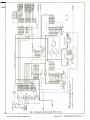
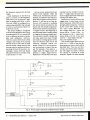
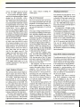
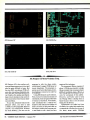
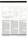
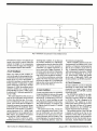
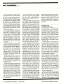
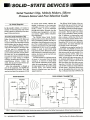
Fig. 2. Schematic details
Say You Saw It In Modern Electronics
of system CPU circuitry.
January 1991
/
MODERN ELECTRONICS
/
15
rmnn
ooxx
n.DD
wIZZ
n
a
I
ZZ
mm
rr
z
D WD
r
<
N
A
D
D
.11
y
o
w
DM
An
III
;ND
W
A
N
M e r-
N
I
n
n
I
<
í<i
m
Z
A
V
D
VI
m
n<
O(n1
n
x
DDDDDDDDDDDDD
NH NrOWmJTUIIWNwO
0000000
00000000
JTNAWNwO
O-NNAN
m
J
0n
00000000
O.-NWANTJ n
I
00000000
0I-NWANTJ
N
n
a
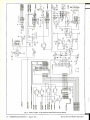
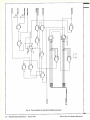
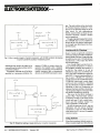
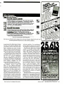
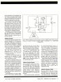
Fig. 3. Input, trigger,
16
/
MODERN ELECTRONICS
/
January 1991
A/D converter and RAM circuitry details.
Say You Saw It In Modern Electronics
information to be displayed. This
process continues until all 64 rows
are filled. Then we start again with
row 1.
Left on its own, the polarized display cell can remain polarized for only about 100 ms, after which it slowly
returns to the background color. To
prevent this from occurring, the cell
must constantly be refreshed to
maintain a high display contrast
level. This is done by the CPU -50 to
60 times each second! The only remaining display signal required is AC
DRIVE, which changes polarity every
frame (64 rows). This is required because chemicals used in the display
will break down if the polarity used
to polarize the cells is not reversed
every frame (much like charging a rechargeable battery). If this signal is
missing, the display will not remain
bright for very long. In our DSO, the
first task performed is a check to see
if the AC DRIVE signal is working.
Learning how LCD displays work
is important because the resolution
of some of these systems is now approaching that of a CRT. Full -color
VGA LCDs are showing up in the
fancier portable computers, and industry expectations of a flat high -resolution television screen will likely
soon be fulfilled.
CPU: The system CPU selected for
our DSO is a high -speed CMOS version of the 8085. It has the advantage
of requiring a minimum of current
and is capable of operating with a
10 -MHz clock input. High speed is a
necessity to meet the refresh requirements of the display. Also, the system needs only a minimal amount of
support chips (see Fig. 2).
The 8085 is an eight -bit processor
with a data bus that is eight bits wide.
Inputs to and outputs from the CPU
consist of eight different signals that
are transferred simultaneously on the
data bus. Notice that the bus is labeled ADO through AD7. This is because these pins also carry address information (addresses 0 through 7).
This scheme is known as multiplex-
Say You Saw It In Modern Electronics
ing the signal pins. Generally, the
CPU sets up the addresses first. They
are then latched into external address
latch register UI.
When addresses are stable, the
CPU issues an ALE (address- latchenable) pulse at pin 30 that latches
the addresses into the latch. During
the rest of the bus cycle, the signals
are data signals. Having a dual -trace
scope (you can add a seconi channel
to our DSO for less than $100) or logic analyzer is the only way to view this
complex signal train. The rest of the
CPU is straightforward. High -order
address lines A8 through Alf are valid
during the entire bus cycle.
The READ, WRITE and 1/o lines set
up the peripherals so that they can
supply or accept data as required by
the CPU. The system's 8K program
ROM, UIO, is at memory locations
0000 through FFF (all locations are in
hex format). The ROM stores program steps and fixed -data tables. The
system's 8K RAM, U8, is mapped
from 8000 through 9FFF. The RAM
holds display data and ogler variables used by the program. (It is not
necessary to understand the hex
numbering system to continue, but if
you are serious about learning, building and designing computer -type circuits you must get some of this behind you.)
Memory & I/O Address Decoders:
The 74HC139 (U4A in Fig. 2) is a
memory map decoder. This chip produces a low -level output at pin 4
whenever the CPU wants to "talk"
to system RAM. A low level at pin 5 is
generated when the CPU is reading
an instruction or data from the system's program ROM. Exactly how
these decoders work will be part of
one of the experiments you will be
conducting in an upcoming issue.
The I/O decoder, a 74HC138 (U3),
operates in much the same manner,
except that when the CPU is addressing an input or output port. the selected port will get a signal from the
I/O decoder, which connects the port
to the system's data bus. Thi.; simple
I
part permits up to eight different
ports to be addressed by the CPU.
This design uses only three ports.
I/O Ports
Display Data Shift Register: The
first port we will analyze is 74HC 165
U2. This simple shift register makes
it possible to get data out of the display memory and into the display.
The CPU outputs eight bits of data
into the eight -bit register inside U2.
The data is moved from system RAM
through the CPU to pins A through H
and into a register inside U2.
The program then turns on the
timer located in the 8155, which generates eight pulses that are sent to the
CLOCK input on U2. Toggling the
clock shifts data, one bit at a time,
out of the register to pin 9. The same
eight clock pulses are used for the
DATA CLOCK signal that loads data
into the display's 240 -bit row register. It takes 30 eight -bit output operations to fill one row of the display;
1,920 output operations to fill all 64
rows just once. Remember, if the display is refreshed 50 times per second
96,000 outputs to the U2 shift register are needed every second. This is
well within the capabilities of the
8085! It is mentioned here to give you
a feel of how interesting the design of
this product is.
8155 I/O Port with Built -In Timer:
The next port we will discuss is the
8155. This chip is innocent in appearance, but it includes two eight- and
one six -bit ports that can be programmed as either inputs or outputs.
It also has a timer that can be started
and stopped that generates a wide variety of waveforms. This chip is a
good example of the new generation
of devices that have to be initialized
with a series of commands before
they become a usable logic element.
An assembly -language program is
required to implement this chip. If
BASIC or another high -level language were used in this design, you
would have to integrate the equiva-
January 1991
/
MODERN ELECTRONICS
/
17
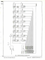
RS2
10K
00
01
02
03
04
os
06
07
DO
D1
D2
D3
D4
os
D6
07
fßDEO.
.77
t!//////1
IM=7r11rl
/111////i4
CIi///ssi
/rr7rsl1
fi=)
1/j1DDr O.
S4-1
.7]
OC
74HC373
LOGIC ANALYZER INPUTS
V C
It:i1.i(i
O
41( I4(=:II9IS'1:\1
O
O
F
+
FißiWI9AF
FYl1Tl114
O F=
41I4(t:T.L1NE
46Z4407:1:L1W10.
411DI9(ItIZfali
B
41d4(tiIIilN,f
41144 ()«L7
4tZ4(LII9Mi
I6Z4(4><n1:L1RSi
VW* CM=Mao
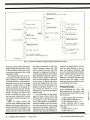
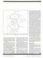
Fig. 4. Circuit details for connection
of optional logic
analyzer inputs.
lent of an assembly- language routine
in your program to deal with initialization and use of the features in this
integrated circuit.
Since integrated circuits have a
growing number of such embedded
functions, the need to know at least
some assembly-language programming becomes increasingly evident.
So if you have avoided the subject in
the past, you should seriously reconsider learning it now. In the real
world, you handicap your hardware
capabilities without knowledge of assembly- language programming. The
digital signal generator article that
will follow soon will offer an opportunity to learn and practice the basics
of assembly -language programming
on an 8088 CPU and associated
peripherals.
Getting back to the 8155, the program initializes Port A as an input
port. This port is connected to the various display mode switches. The
program reads this port and decides
if the system is in the single -sweep
mode in displaying the eight -channel
logic analyzer, analog Channel A,
Channel B or both.
18
BUS
Fig. 5. Circuitry is provided for connecting into the system
an optional Channel B circuit via its a 28 -pin bus connector.
Port B is initialized as an output
port. Signals generated at these outputs clear the address counter, direct
the data RAM read and write modes,
select the logic analyzer or the analog
inputs and control the trigger -enable
logic that is used in the single -sweep
mode. Port C is also set up as an output port. Signals here produce the
logic to control display action, as
described earlier. The timer is programmed to produce a square -wave
output with the frequency needed to
clock the data out of the U2 shift
register and into the display.
Data RAM Input Ports: The last
ports to be reviewed are those that
read data collected by the data RAM.
Referring to Fig.3, note that OUTPUT
CONTROL pin of U21 goes low when
inputs to U6D are high. The 8155
supplies one of the signals to CHAN A
or LA, which goes high when the unit
is displaying either Channel A or
logic- analyzer signals. The other input to U6D is I/O select line Cz FX,
which is generated by the I/O decoder discussed above.
When the CPU wants to read this
data RAM, it issues the signals that
/ MODERN ELECTRONICS / January
1
1991
connect U21 to the data bus. If the
scope is displaying Channel B, the
8155 produces a high level at pin of
U22A. Pin 2 receives the CS FX signal. The resultant READ B \ signal is
sent to the Channel B bus (see Fig. 5).
Channel B is not shown at this time,
but consists of the same components
and signals that are in Fig. 3, except
for the trigger and some of the I/O
logic already used for Channel A that
is common for both channels. The
bus permits the Channel -B board to
be plugged into the main board. Inputs and controls are located just behind Channel A controls.
Analog Inputs: Now look at the analog input circuit area in Fig. 3. The
inputs from either J6 or J7 are coupled to the input of the first AD843
operational amplifier through SW2.
This switch configures operation of
the input circuit for either ac or dc
coupling. A center position on this
switch grounds the input to provide a
convenient 0 reference point. INPUT
ATTENUATOR SW3 permits selection of a divide -by -2, -20 or -200. Capacitors C42, C43 and C44 are small
trimmers that you adjust to provide a
1
Say You Saw It In Modern Electronics
A Shocking Offer!
Now for the first time in CIE's 56 year history you do
not have to be enrolled at CIE to receive our introductory Electronic and Electricity Lesson Modules.
Available for a limited time to non -students for the
shockingly low price of only $99.50.
With CIE's patented AUTO -PROGRAMMED
method of learning you'll quickly learn and then
master the basics of electronics and electricity and
then move on to... DC /AC circuit
theories, fundamentals of bi -polar
junction transistors (BJT), field
effect transistors (FET),
wiring, diagram and schematic readings, component
identification, soldering
techniques... and much,
much, more.
Your commitment to CIE
ends with your payment, but
CIE's commitment to your
success just begins when you
receive your
39 lessons, exams, birders and equipment. This
special introductory price includes all the benefits and
assistance CIE normally extends to its students and
graduates. You'll be e ititled to unlimited access to
CIE's faculty aid staff to assist you in your studies via
a toll tree 800 number six days a week, 24 -hour
turnaround on grading your submitted exams, CIE
Bookstore privileges, a patented learning method,
reference library, a student, faculty
and alumni electronic
bulletin board and a free
issue of CIE's school
newspaper The Electron.
All this knowledge and
support will put you on the
road to understanding
digital electronics,
microprocessing princples,
computer systems. telecommunications, and
much, much,
more.
I
+òQ
06ct
\
4E5
_
44.tm
All This and Much More
For ONLY!
Free Issue of The Electron
Build your personal burglar alarm
Instructors available 6 days a week
20 lesson books containing 39
theory and hands -on training
lessons and exams.
Bookstore Privileges
Patented Learning Method
Electronic Bulletin Board
24 -Hour Grading
Yes, send me CIE's 39 Introductory Electronic
and Electricity Lessons and Equipment.
I
Name:
Address:
Apt. #:
City:
Zip:
State:
Age:
i
Method of Payment: Amount Enclosed
Personal Check or Monev Order
1 Master Card n Visa
1
$
Card Expiration Date.
Phone
BOOKSTORE
1776 Ea.1 17th
l:lrveland.
Signature
SIr,,t
1/hilo LII
12161781-9 t1111
BK04
$99 50
Total Merchandise.
Ohio Residents add 7% Sa es Tax:
California Residents add 6 -1/2% Sales Tax:
Total this order:
I
f
CHARGE BY PHONE!
9 AM
i
V
to 4:30 PM Eastern Time; from Ohio 1-800-523 -9109
from all other states 1- 800 -321 -2155
As you can see, analog circuits are
almost trivial elements within the
whole circuit. Furthermore, the components are expensive and require a
great deal of support resistors and capacitors. It will not be too long before an A/D converter is available
that can be directly connected to the
inputs that will include programmable level and sensitivity adjustments.
Trigger Circuits: The beginning of
each horizontal trace is usually started
or triggered by the input signal train.
You can select a specific voltage that
the input signal must pass through
(DC mode) or a voltage greater or less
than the reference point set by the
VERTICAL POSITION control (AC
mode). Using SWI, you can also select the direction or slope of the signal. For example, if you select a +
trigger slope, the trigger circuit will
generate a trigger signal (low -tohigh) at pin 7 of U26 only if the input
flat frequency response for all three
ranges.
Input impedance of the FET op
amp is in excess of 100 megohms,
while INPUT Z to the scope is megohm in parallel with 20 pF ± 10 %.
The first AD843 is configured as a
noninverting amplifier that includes
a VERTICAL GAIN control. Gain is variable from 2 to 10.
The second AD843 is configured
as an inverting amplifier that is set to
provide a gain of 10. CAL control R23
is set to calibrate the input to the display scale calibration. VERTICAL
POSITION control R24 sets dc offset
voltage at the output of the op amp
between 0 and 5 volts. Bear in mind
that the output voltage swing of the
op amp must be restricted to the input range of the A/D converter. Accordingly, resistor R16 and diodes
D6 and D7 limit the A/D input swing
to ground and + 5 volts.
1
going from low to high. If you setrigger slope, the input produces a trigger signal only if the input
is going from high to low.
TRIGGER GAIN control R26 sets the
trigger point. In most cases, you set
R26 to maximum. Chip U26 is a simple high -speed comparator. TRIGGER
SLOPE switch SWI simply reverses
the + and - inputs. When the + input is higher than the - input, the
output will be +5 volts. If the - input increases to the + input level,
output drops to 0 volt. If you start
with the - input higher than the +
input, the opposite occurs.
The normal trigger signal must go
from 0 to + 5 volts to start the address generator circuit, which will be
described later. You can use TRIGGER SEL switch S4 to select which input will trigger the system. Choices
are Channel A, Channel B, Logic
Analyzer, Signal 0 or some external
is
lect a
-
U20
LM780S
1
T
OSA
3
1
C24
C22
T.IUF
2.2UF
R6
47
T
M/
/2W
0 +12A
1
IC26
C25
2.2ÚF
T
22UF/16V
12V
OVCC
T
litC27
2.2ÚF
0 +5 VOLTS
OVDD
r
RS
O-12A
47 1/2W
V
-1552
-
C28
C29
!I2.2UF
I22 UF/16V
VIGCOLTS
O 12V
i
.IUF BYPASS CAPS
11
11
11
TTTTTTTTTTTTTTTTTTTTT
1
C2
C3
C4
CS
C6
C7
C8
C9
C1O C11 C12 C13 C14 C15 C16 C17 C18 C20 C19 C23 C21
Fig. 6. Power supply required is straightforward in design.
20
/ MODERN ELECTRONICS / January 1991
Say You Saw It In Modern Electronics
MI
WV
-
W
Jr
Oa
O¢
Om
Ou
00
oa
coal
OV
VJIC
00 _AL
l
a
CO
CD
-.
Jr
a© VY¢
VYaI
uJR
N
da
Oa
Om
OV
r
ry
oa
Om
ou
VJI 00
m
m
VI
mV
rZ
-.o
CO
MI
Jr
a
-.° V VYm
P
VAT
a
Jr
a
Oa
om
OV
00
N o
s
ooa
OV
coo
a
M
a
I
-a
Jr
MI
¢
VYa
ai
VYm
N
VJa
rv
O¢
Om
OV
_
VJa 00
L
n
7l
al
M
a
mV
m
aa
NI
Jr
-1
Jr
VYa
aß
VYm
a
w
H]
vJrc
VJC
aal
Om
ou
00
T
m
pl
T
aV
DZ
Jr
oa
om
W
V Ja 00
"O a
7;
N
n
al
aT
M
mV
-I
W
NI
Jr
-I
Jr
VY¢
OW
Om
O
©a
N
V JK
ir
T
M
;r7
CO
H
aV
IP
-a
Jr
VYa
4,
rv
VYm
VJa
oa _p
Om
ou
00
I
Jr
OI
O(a
OV
Ot]
Óa
N
V_ItC
oa
Om
Ou
00
?
VO
I
}
\9T4\4
V
w
M
.\
w
J a
N_
w w
I
J
O
uu..
Fig.
Say You Saw It In Modern Electronics
7.
l¡.r}AA'
u:Mí4ií+Jíi
Schematic details for timebase circuit.
January
1991
/
MODERN ELECTRONICS /
21
source. The trigger circuit can be set
to one of four different modes.
In AUTO mode, the trigger is generated by the timebase generator signal
divided by 40 (CLK /40). LEVEL,
SLOPE and GAIN controls have no effect. This mode is not used frequently and is generally employed to make
the signal display on the screen. The
most common mode is NORMAL, described above. Just set trigger controls for the desired display. Note
that the display blinks slightly every
0.3 second. This blink occurs when
the program is reading the data RAM
and moving data collected to the display area in system RAM.
Once you have the display you wish
to study, press ARM /FREEZE switch
S5 to freeze the display. SINGLE STEP
mode is used if only one pass of the
signal is desired. To use this mode set
TRIGGER MODE switch S2 to SINGLE
STEP; then when you are ready to
wait for the trigger, press S5. The
trigger circuit will then wait for a trigger signal. After this signal is received, data is stored and displayed.
To repeat single -step action, press S5
again. The last selection in S2 selects
if the trigger signal used is ac or dc
coupled. Note that EXT TRIG input J8
is ac- coupled only.
Logic Analyzer Circuits
The optional eight -channel logic analyzer's inputs are shown in Fig. 4.
The program produces the LOGIC ANALYZER WR \ signal that connects inputs buffered by U19 to the data
RAM data inputs when incoming data is being written to the RAM. The
LA TRIG signal from input data line
DO is coupled to TRIGGER SEL switch
S4 through buffer U27A. These inputs are pulled high. So, when an input is not being used, the display will
indicate a high level for that input.
The input cable assembly consists
of a 14- conductor ribbon cable with
nine hook connectors. This provides
a ground wire between each connec-
22
tion, which reduces coupling between inputs.
The A /D Converter
The A/D converter (see U25
in Fig.
3) is a high -speed flash -type unit that
produces a six -bit digital output. To
perform a conversion, the input circuit uses 64 comparators. It works as
follows.
If the input voltage compared to bottom reference VRB at pin 10 of U25 is
zero, the binary digital output will be
000000. If the input is the same as top
reference VRT at pin 9, the binary digital output will be I II. Should the
input exceed the top reference, the
OVERFLOW signal at pin 2 will be a
On the rising edge of the clock, comparator outputs are clocked into internal decoders. On the falling edge
of the clock, digital output is clocked
to the output pins. See Fig. 9.
Now we get into a slightly tricky
area. Note that output signals of U25
connect to data lines of data RAM
U28, the data side of the U21 input
port and to outputs of logic analyzer
latch U19. These chips cannot be activated at the same time.
The program, via Port B of the
8155, supplies signals that select or
connect the proper chips as they are
required. A/D converters are selected only when the AD WR \ is low.
This puts the CEI \ line at pin 6 low,
activating U25 and connecting it to
U21 while data is collected. This occurs only if you selected Channel A
or B and the proper trigger conditions have been met.
If you select the logic analyzer, the
program will supply a low at LOGIC
ANALYZER WR \ pin of U19. Thus,
logic analyzer inputs are connected
to data RAM, permitting data collected to be stored in the RAM. Data
RAM U21 transfers data stored in it
through a program that places data
in the display RAM area. It does this
in the format required for it to be sent
to the LCD display.
/ MODERN ELECTRONICS / January 1991
I
I I
I .
1
Timebase Generator
The timebase circuits (see Fig. 7) are
simple enough. 74HC393s are used
to divide by 10 the input to pins CKB.
The output at pins QA is a square
wave with '/,0 the frequency of the input. The 74HC390s divide Input A
by 2 at the QA pins and divide Input A
by 4 at the QB pins.
You begin with a 20 -MHz oscillator and divide by steps of 2, 4 and 10.
This produces a timebase with industry- standard 1/2/5 separations. Output PCLOCK provides the 10 -MHz
clock to the CPU. Other outputs, selected via J2, supply timebase signal
AD CLOCK to the address generator,
the A/D converter and data RAM.
You use the signals produced by
these circuits to adjust frequency compensation capacitors to obtain a
flat frequency response in the analog
input attenuator.
Data RAM Address Generator
The address generator (Fig. 8) is used
exclusively to produce addresses for
the data RAM. In data write mode
that is, when the A/D or logic analyzer is writing data to the data RAM
the addresses to data RAM must be
generated in synchronization with
data being supplied by the A/D converter or logic analyzer. Therefore,
they are indexed or incremented by
the AD CLOCK signal.
When the CPU wants to read the
data RAM, addresses to the RAM
are not supplied by the CPU. Instead, data RAM is read by the CPU
like an I/O port. The RAM addresses
are indexed by the chip -select signal
generated by the I/O decoder signal,
CS FX \ . See Fig. 9 for the timing diagrams. The logic analyzer can be very
useful when verifying the timing of
these kinds of signals.
The addresses needed are generated
by the dual four -bit- counters inside
74HC393 U29. The address generator
is first set to zero by the CLEAR CTR
-
Say You Saw It In Modern Electronics
SELECT 5 BOOKS
for ont y $495
ELECTROSTATIC
DISCHARGE
PROTECTII71
(values to $129.70)
and get a FREE Gift!
.ra.r.d..-+.
111310 EQUIPM1\1
Irarcr.,;;;z6:
CIRCUITS
VOLUME -ONE
7.rr--;
Counts as
FIBEROPTICS
Sotuirl
synthesis
APDLASER
3329
to;°v
°°,,
`.
529 95
Counts
as.
$18.95
2867P
3
2
:
2981P
51695
3276
522 95
tHE L1111 Sunk ul
ELECTßO1IfS
John
O
10018
PROJECTS
Lu,4
539.95
Counts as
2
r
ELECTRONIC
CaiCl.%Ts
wrTTi
PRACTICAL
2898 515.95
l
APPL.lCAT10tJ5
3260
$22.95
For over 25 years, your most complete
source for electronics books.
C.a7rIC ante
Y
$24.95
1
,,
nil-swim
$29.95
Counts as 2
2920
1367P
MONA
osccascures
2826P
S16 95
r
2279
536 95
Cou ats as 2
1604P 517.95
Now to
F
3157P
519.95
1532P
M16unP
3307
$14.95
526.95
Counts as
2
aa11;410tr tNls
..d
Ctr. uit
[4aonlr
Dregs ms
fsalllli Al1lE!
8080T BUILDERS
BONANZA
603fl951Yl
OOnKS
5-
3031P
517.95
3138
2980P 514.95
rar
liwc
th.N
I tTCita1
-3374
O I
.r...
I
521.95
Counts as
2
3370
C
nun
525.96
as 2
s
¡
66611a
I
524.95
3072P
$16.95
ELECT-FMCS
15 Easy
529.95
Counts as 2
$16.95
B K CLUE!
Electronic Projects
Projects you can build -some unique,
some old favorites -from the author's
vast treasury of electronics know -how.
WW1
urN!
2800P
an.1111111
3360
FREE when you join the
From Delton T. Horn
11.111=111111
3
sparr Sorel
F:krtnxlx.
n.rni Irntro Lnr
560.00
Counts as
14n' &N ad tes 1
804P
2
rYlBrt
.
DeitalT.Hlxn's
AO-Time Favorite
Electronic Projects
IILIER DESIGN
o
New to Tart
Atmest
..rytm..r
alestrek
3355
2925P
A
$7.95
Value!
Z,w.1s'
11
89.95
ANTENNA
526.95
Counts as 2
62 HOME
REMOTE
CONTROL
PN6iiC",
AUTOMATION
Membership Benefits
3205
3312
$24.95
$23.95
3241P 316.95
2633P 317.95
All books are hardcover unlf'tss number
is followed by a P" for paperback.
Big Savings. In addition to this introductory
offer, you keep saving substantially with members' prices of up to 50% off the
publishers' prices. Bonus Books. Starting immediately, you will be eligible
for our Bonus Book Plan, with savings of up to 80% off publishers' prices.
Club
News Bulletins. 15 times per year you will receive the Book Club News, describing all the current selections- mains, alternates, extras-plus bonus offers and
special sales, with scores of titles to choose from
Automatic Order. If you
want the Main Selection, do nothing and it will be sent to you automatically.
If you prefer another selection, or no book at all, simply indicate your choice
on the reply form provided. You will have at least 10 days to decide. As a
member, you agree to purchase at least 3 books within the next 12 months and
may resign at any time thereafter.
Ironclad No-Risk Guarantee. If not satisfied
with your books. return them within 10 days without obligation!
Exceptional
Quality. All books are quality publishers' editions especially selected by our
MDNE191
Editorial Board.
A shipping /handling charge and sales tax will be added to all orders.
card is missing, use this address to join:
ELECTRONICS BOOK CLUB. Blue Ridge Summit. PA 17294 -0810
If
3270
S32.95
Counts as
2
2735P
516.95
WAIL.
ELECTRt''' FIX.IT Bo
2790P
$14.95
2883P
$17.95
(Publishers' Prices Shown)
1991 ELECTRONICS BOOK CLUB
N
A
C
N
D
1:13
n
n
n
N
0
rn
V
O
D
N
0000
N
ñ
d
CD
C
rn
01
n
x
o
nv
0
P
ñ
r-
Na
NC
W
CO
N
N
D
m
HN
C
O
C<CC
VOV9
DDDD
00
4400
JRMIa
\\\\
Fig. 8. Circuit details for data RAM address generator.
26
/ MODERN ELECTRONICS / January
1991
Say You Saw It In Modern Electronics
the CS FX \ signal. If the CPU is reading the data RAM, addresses are indexed or generated by the falling
edge of the CS FX \ signal. However,
if addresses are generated to be used
as addresses while writing data to the
data RAM, inputs to the counter are
generated by the falling edge of the
AD CLOCK signal.
The CPU issues a high to the DISP
RAM WR line to open the channel of
AD CLOCK pulses to the counter if the
proper trigger has been set. Note that
the U33 flip-flop is reset at the same
time as the counter is set to zero.
Once the trigger has been satisfied by
either a normal or auto trigger signal,
the gates are opened. This action allows the AD CLOCK signal to index
and generate addresses. If the CPU is
reading the data RAM, it generates a
high at DISP RAM RD. This allows the
CS FX signal to index the counter, thus
producing the addresses for the data
RAM read cycles.
signal generated by the CPU. This
sets the counter's outputs, which are
the address signals to 00000000. Every
input count (high -to -low transition)
increments the address by one. Every
to
16 counts produces a binary
appear at the inputs of U32A. This
produces a high at the output of
U32A. The very next count produces
a low -going pulse at the output of
U32A, thus generating a count at the
input of second counter U29B.
When the second counter reaches
16 counts, all outputs are high, or
11 t u t u.
Consequently, addresses
generated increase from 00000000 to
11111111 (binary), from o to 255 (decimal) or from o to FF (hex). After
reaching the last address, the output
of U32B goes high, signaling the
CPU via the READ AD signal that the
data RAM is waiting to be read and
displayed.
Input counts to the counter are
generated by either the AD CLOCK or
1 1 1 1
Power Supply
The power supply, shown schematically in Fig. 5, is "plain vanilla" in
design. You must supply a regulated
+ 5 volts at 350 mA and ± 12 volts at
100 mA. Note that a separate 5 -volt
supplies reference voltages to the
A/D converter and trigger comparator. This decouples the digital and
analog supplies to reduce coupling of
digital pulses and noise into the analog channels. Be sure to locate the
transformer away from the analog
inputs to avoid any stray electrical
fields and noise.
Program Software
Software required for this project is
basically very simple. The tasks are
illustrated in Fig 10. When the system
is turned on, or RESET switch SI (Fig.
2) is pressed, the CPU starts at the beginning of the task list. First it performs a bit of system management,
DATA RAM WRITES
ADDRESS LINES
AD CLOCK
RAM WRITE
AD CLOCK
CTO A TO D CONVERTER:
ADDRESSES GENERATED BY THE
ADDRESS GENERATOR ARE DELAYED
DUE TO PROPAGATION DELAYS
ADDRESSES INCREMENT ON FALLING EDGE
DATA RAM WRITES ON RISING EDGE
DATA VALID AT OUTPUTS OF A TO D ON RISING EDGE
DATA RAM READS
ADDRESS LINES
CS F%\
RD\ (FROM CPU)
ADDRESSES GENERATED BY THE
ADDRESS GENERATOR ARE DELAYED
DUE TO PROPAGATION DELAYS
ADDRESS INCREMENTS ON FALLING EDGE
[-----RTADS DATA
TO CPU
Fig. 9. Timing details for data RAM writes and reads.
Say You Saw It In Modern Electronics
January 1991
/
MODERN ELECTRONICS / 27
RESET -POWER ON
INITALIZE STACK. 8155 I/O &TIMER
CLEAR SCREEN
ADD GRIDS
START
DISPLAY SCREEN
DISPLAY SCREEN
ARM/FREEZE MODE SET
?
CHAN A. B. BOTH OR
LOGIC ANALIZER
FREEZE MODE
.3
SEC
?
41111
NO
YES
SINGLE
DID WE GET TRIG ?
SINGLE SWEEP OR NORMAL
SWEEP
URN ON
RIGGER ENABLE
4111111
NORMAL
DID WE GET TRIGGER
NO
YES
?
READ DATA RAM AND
FORMAT DISPLAY RAM
GO TO START
YES
DID WE GET A FREEZE ?
READ DATA RAM AND
FORMAT DISPLAY DATA
NO
GO TO START
SET
FREEZE MODE THEN
YES
SET ARMED STATUS OFF
GO TO START
GO TO START
GO TO START TO DISPLAY
DATA AND WAIT FOR ARM/FREEZE
BUTTON
GO TO START
Fig. 10. Software details for simple program requiredfor project.
setting up a stack pointer and initializing the 8155 ports and timer. Next,
it fills the display RAM area with Os
to clear the screen and the data to add
the display's grids.
The program then looks at the various mode switches to set up for display of Channel A, Channel B, both,
or the logic analyzer. Additionally, it
concludes if you set up in the Single
Sweep or Normal mode. If Single
Sweep is selected, the program displays the cleared screen and waits for
you to press the ARM /FREEZE button.
While it is waiting, the CPU is constantly refreshing the screen. Once
you press the ARM /FREEZE button,
the system is armed and awaits a valid trigger.
When the trigger arrives, the
counter starts generating data RAM
addresses and stores data being collected in data RAM. (During the collection time, the LCD display is still
being refreshed.) When data RAM
28
/ MODERN ELECTRONICS / January
has collected 256 slices of data, the
address generator signals the CPU
that it is ready to be read. The CPU
responds by stopping everything to
read the data RAM. It then formats
data collected and places it in the previously cleared display RAM area.
Now the data collected is displayed
on the screen. In Single Step mode,
the data is displayed until the ARM/
FREEZE button is pressed again. The
program constantly checks to see if
you pressed the button or if you
changed your mind and switched to
another mode.
If you selected the Normal mode,
much the same occurs, except that
collected data is displayed for only
0.3 second at a time. If during that
time a valid trigger occurs and different data is collected, the CPU collects
that data and places it in the format
required by the display. Display offtime is about 25 ms. During this time,
the CPU reads the data RAM and re-
1991
formats the display RAM. This results in a slight blinking of the display. The program constantly waits
to see if you pressed the ARM /FREEZE
button, which freezes the current display. This action eliminates the
blinking. If you again press the ARM/
FREEZE button, the trigger is re -enabled and the scope continues to capture and display new data.
Testing the Scope
After assembling the DSO from
plans presented in this article, here
are the steps you should follow to test
the instrument:
(1)
(2)
(3)
(4)
Set TRIGGER MODE to NORMAL.
Set trigger coupling to AC.
Set TRIGGER SLOPE to + or .
Set TRIGGER GAIN to maxi-
mum and
-
TRIGGER LEVEL
to center
of rotation.
(5) Set RANGE to IV /DIV.
(6) Set IN SEL to AC.
Say You Saw It In Modern Electronics
(7) Feed a 5 -kHz square -wave signal into input J6 or J7.
(8) Set the input level, VERT GAIN
and VERT POSITION to obtain a centered display. If you do not have a
signal generator, see below. Adjust
trimmer C44 to obtain a square wave.
(9) Set RANGE to the .1V /DIV, and
reduce the input signal level to obtain
a centered display.
(10) Adjust trimmer C43 to obtain
a square wave.
(1 1) Set RANGE to .OIV /DIV and adjust the input to obtain a centered
display.
(12) Adjust trimmer C42 to obtain
a square wave.
If you do not have a signal generator, connect the scope input to pin 4
of U16. Set the timebase to 20µs /div.
The input will be approximately 5
volts. To reduce the input voltage as
required in the following steps, connect a 2,000 -ohm variable resistor
from pin 4 of U16 to ground. Connect the wiper to the scope input.
Then adjust the resistor to center displays for the rest of the adjustments.
To make sure that you have the ac
drive signal at the display, set the
RANGE switch to IV /DIV and connect
the scope input to pin 3 on the display. Then set the timebase generator
to S ms /div. You should see a square
wave with a 40- millisecond period in
the display.
The only other adjustment is for
vertical sensitivity CAL control R23.
This can be made by setting the IN
SEL switch to DC and measuring the
dc voltage at the output of U20. Set
the CAL control so that the baseline
moves five divisions when connecting the input of the scope project to
the output at U20.
Next month, the series will show
you how to build a function generator and lay the ground for putti,-7g together a digital signal generator.
Upon completing the instrument
foundation, a host of application experiments will follow in later issues
that utilize these test /research /deAE
velopment instruments.
Double your income!
Computer maintenance /service
-a $10 billion industry.
If you are presently servicing office machines or any other electronic equipment,
computer repair can double your Income.
National research results indicate that computer technicians bill out at double the
hourly rate of office machine technicians.
Tech -Sery con put you into computer repair quickly, economically and efficiently
and with a complete support program including a proven marketing plan.
We provide:
RECOGNITION
Notionally recognized trademarks and
logos give you immediate recognition as
a professional computer repair specialist
by being a Tech -Sery Authorized Complier
Repair Center in your market area.
DOCUMENTATION
We provide manuals, schematics, documen-
and compatibles at
3
separate levels:
8086-8088 Based Machines
DOS System Configuration
Level 1:
and upgrades
80286/80386 Machines, Letter
Quality and Laser Printers
System Networks Configuration,
Level 2:
Level 3:
tation and advanced diagnostic software.
Installation and Repair
FINANCING
NEW HARDWARE
CPU's: IBM Apple, Compaq, and others.
Printers: Okidata, Epson, -IP Lasers and
others at huge discounts.
t-
PARTS & BOARD REPAIR
Single source for parts and board repair.
24-hour express turnaround.
Available for qualified businesses.
OVER 125 DEALERS WORLDWIDE
Find out why more and more electronic
professionals are adding computer repair to
their businesses or starting their own computer repair businesses.
Call Tech -Sery at (212)967 -1865 now.
servi.,
SERVICING THE WORLD OF MICROS
01989 Tach.Ser. Corp.
253 West 28th Skeet, New York, NY 10001
(-lR(.11. NO. 8ON FREE INFORMA1IUN ( ARD
LEARN ELECTRONICS FROM VHS VIDEO TAPES!
(JCRnDO
=
Success
4
Our Video Tapes
Are Designed
To Make Learning Electronics
Fun and Eas!
PART 1 -DC, 53 min
$32.95
PART 2 -AC,
$32.9!
Electronics and You -VT -201
PART 5-AMPLIFIERS
52 min
71 min
Electronics and You -VT -202
$32.95
Electronics and You -VT -207
PART 6-OSCILLATORS
47 min
$32.95
Electronics and You -VT -205
$32.95
54 min
PART 3 -SEMICONDUCTORS,
Electronics and You -VT -208
VCR MAINTENANCE & REPAIR
VT- 203 -54 min
PART 4 -POWER SUPPLY
55 min
$32.95
Electronics and You -VT -206
$32.95
INTRODUCTION TO VCR REPAIR
VT- 204 -110 Min.
$59.95
CALL TOLL FREE AT
1- 800 -678 -6113
or
mail check or money order to:
UCANDO VIDEOS
P.O. BOX 928
CIRCLE NO.
Say You Saw It In Modern Electronics
TRAINING
Hands on training: IBM, Compaq, Apple,
21
VISA
AND
CARD
MAACCEPTED
GREENVILLE, OH 45331
ON FREE INFORMATION CARD
January 1991
/
MODERN ELECTRONICS
/
29
COMMUNICATIONS
AOR
Scanners.
Great Performance. Great Service. Great Value.
Free Freight
25 -Day Money -Back Guarantee
Toll -Free Service and Support
No Credit Card Surcharge
One Year Warranty
$499
ÁR1000
1000 Channels. 8- 600MHz, 805- 1300MHz
Standard Features:
Extremely compact size.
Continuous coverage (except UHF TV 600 -805)
Antenna attenuator switch, 10db.
Manual tuning knob.
Earphone jack, 3.5mm.
AM, FM and wide band FM tuning modes.
Backlighted LCD display.
10 Scan Banks, 10 Search Banks.
Selectable Priority Channel.
Delay, Hold Features.
Selectable Search Increments, 5- 955KHz.
Permanent memory backup.
4 AA Ni Cad batteries included.
AC adaptor /charger.
Carry Case.
Cigarette Lighter Charger.
Earphone.
Options:
External Speaker. Mobile Mount.
Extended Warranty. 2/3 yrs
IF:
r
30
Increments:
Audio:
Power:
Antenna:
Display:
Dimensions:
MS190 $19.50
$45/$55
8-600, 805,1300MHz
.35uV NFM, 1.0uV WFM, 1.0AM
20 ch /sec. scan. 40 ch /sec. search
561.225, 58.075, 455KHz or 10.7MHz
5 to 955KHz selectable/ 5 or 12.5 steps.
Watts
Input 9 -13.8 V. DC
.4
BNC
LCD
6
100 Channels. Low, Air, High, UHF &
800MHz.
Standard Features:
Extremely compact size.
Unrestricted 800MHz coverage.
100 channels permanent memory.
Earphone Jack & Attenuator.
Delay, Hold features.
Channel 1 Priority.
5 Scan Banks, 5 Search Banks.
Telescopic and Flexible Antennas
w/ BNC connector.
AC & DC Power cords w/ mtng hardware.
One Year Limited Warranty.
Options:
Base type antenna
Belt Clip.
Specifications:
Coverage:
Sensitivity:
Speed:
$239
AR950
7/8H x 1 3/4D x
2
1
/2W. 12oz wt.
AS300 $59.95
25 to 1000MHz w 50'coax.
Mag Mnt Mobile Antenna. 15' coax. MA100 $25.00
CP100 $4.00
Cigarette Lighter power adaptor.
External Speaker
MS100 $19.50
with mobile mount.
$40/$55
Extended Warranty. 2/3 yrs
Specifications:
Coverage:
Sensitivity:
Scan Speed:
27 -54, 108 -174, 406 -512, 830- 950MHz
.4uV Lo,Hi. .8uV Air. .5uV
UHF. 1.0uV 800
15 ch /sec.
21.4MHz, 455KHz
Increments: 10,12.5,25,30
1W
Audio:
12.8VDC, 200MA
Power:
BNC
Antenna:
LCD w /backlight
Display:
Dimensions: 21 /4H x 5 5/8W x 61 /2D. 14oz wt.
IF:
We offer 100's of communications products.
/
MODERN ELECTRONICS
/
January 1991
Say You Saw It In Modern Electronics
COMMUNICATIONS
AR3000
AR2500
$995
$499
400 Channels. 100KHz to 2036MHz.
Standard Features:
2016 Channels.
1
MHz to 1500 MHz
Standard Features
Continuous coverage
AM, FM, wide band FM,
& BFO for SSB, CW.
64 Scan Banks.
16 Search Banks.
RS232 port built in.
Includes AC /DC pwr crd. Antenna, Mntng
One Year Limited
Brckt.
Warranty.
Options:
Earphone.
EP200
$2.00
External Speaker. Mobile Mount.
MS190 $19.50
Extended Warranty. 2/3 yrs.
$65/75
Mobile Mounting Bracket.
MM1
$14.90
RS232 Control Package
SCS2
$295.00
(software & cable) offers spectrum display
and database.
Specifications:
Coverage:
Sensitivity:
Speed:
IF:
Increments:
Audio:
Power:
Antenna:
Display:
Dimensions:
MHz - 1500MHz
.35uV NFM, 1.0uV WFM,
1.0AM /SSB /CW
38 ch /sec. scan. 38 ch /sec. search
750.00, 45.0275, 5.5MHz 455KHz
5,12,5,25 KHz
1
1.2 Watts at 4 ohms
Input 13.8 V. DC 300mA
BNC
LCD, backlighted.
2 1/411 x 5 5/8W x 6 1/2D Wt. 11b.
Extremely compact size.
Continuous coverage
Attenuation Programmable by Channel.
Manual tuning knob.
Tuning increments down to 50Hz.
AM, FM, wide band FM, LSB, USB, CW modes.
Backlighted LCD display.
4 Scan and Search Banks, Lockout in Search.
4 Priority Channels.
RS232 control through DB25 connector.
Delay, Hold Features.
15 band pass filters, GaAsFET RF amp.
Sleep and Alarm Features.
AC adaptor /charger. DC power cord.
Telescopic Antenna.
Options:
Earphone.
EP200 $2.00
External Speaker. Mobile Mount.
MS190 $19.50
Extended Warranty. 2/3 yrs.
$65/75
Mobile Mounting Bracket.
MM1
$14.90
RS232 Control Package
SCS3
$295.00
(software & cable) offers spectrum display
and database.
Specifications:
Coverage:
100KHz - 2036MHz
Sensitivity: .35uV NFM, 1.0uV WFM,
1.0AM /SSB /CW
Speed:
20 ch /sec. scan. 20th /sec. search
IF
736.23, (352.23) (198.63) 45.0275, 455KHz
Increments: 50Hz and greater
Selectivity:
2.4Khz /-6db (SSB) 12KHz / -6db
(NFM /AM)
Audio:
1.2 Watts at 4 ohms
Power:
Input 13.8 V. DC 500mA
Antenna:
BNC
Display:
LCD
Dimensions: 3 1/7H x 5 2/5W x 7 7/8D Wt. 21b l0oz.
To Order Call i 800.445.7717
In All 50 States and Canada. 24 Hours a Day. Fax Orders: 1- 800 -448 -1084, 24 Hours a Day.
ACE Communications Monitor Division 10707 E. 106th Street, Fishers, IN 46038
Int'l Voice# 317-842 -7115. Int'l Fax# 317-849 -8794.
Service and Support Lines: Mon-Fri 9a.m. to 9p.m., Saturday 10-4. EST
MasterCard, Visa, American Express, Checks, Approved P.O.'s. & C.O.D. (add 5.00)
Prices and specifications subject to change.
CIRCLE NO. 52 ON FREE INFORMATION CARD
Say You Saw It In Modern Electronics
January 1991
/
MODERN ELECTRONICS /
31
Project
The "Watt Watcher"
Inductivepickup meter
monitors instant ac power
usage so that you can
more efficiently manage
energy consumption
By Dennis P. Blum, CET
The kilowatt -hour meter your
local utility company installed
on or in your home measures
electric power consumption. However, being an accumulating device,
it is not overly useful for the homeowner who wants to monitor power
used for conservation purposes. The
"Watt Watcher" described here, on
the other hand, displays actual power
usage in kilowatts from moment to
moment without ambiguity. Any
change in load, such as a refrigerator
switching on or a lamp being switched
off, immediately registers on a built in meter movement.
The metering system consists of
two inductive-pickup devices you
mount inside your electrical service
box (no potentially hazardous connections are required) and a remote
indicating panel meter and driving
circuitry. The circuit is self-powered,
eliminating any need for a battery or
connection to the ac line.
About the Circuit
Shown in Fig. 1 is the complete schematic diagram of the Watt Watcher
circuitry. Inductive pickup coils LI
and L2 are remotely located from the
circuitry, in the electrical service box.
They provide a voltage to transformer Tl that is directly proportional to
the amount of current flowing in
each leg of the ac power line supplying your home.
Any voltage that appears at the input to Ti from L1 and L2 is stepped
up by transformer action and applied
to the full -wave bridge rectifier circuit made up of diodes Dl through
D4. After rectification, the pulsating
dc from the rectifier circuit is filtered
to pure dc by capacitor C1 and passed
PARTS LIST
C1- 10-µF, 10 -volt electrolytic capacitor
Dl thru D4 -1N914 or similar diode
L ,L2-Inductive pickup coil (see text)
MI-50-AA full -scale analog panel meter movement (Radio Shack Cat. No.
270-1751 or similar)
RI,R2,R3 -See text for value
S1-3-position, non -shorting rotary
1
II
Twisted
pair of
bell wire
Li
IIL2
Remote
pickups
NOTE:
'Values determined
during calibration.
Fig. I. Complete schematic diagram
32
of circuitry used in the
/ MODERN ELECTRONICS / January 1991
Watt Watcher.
switch
T1- 12.6 -volt power transformer (Radio
Shack Cat. No. 273 -1365 or similar)
Misc. -Suitable enclosure; transformer
for pickups (see text); two multiple lug terminal strips; control knob for
S1; twisted-pair bell wire; tape; cable
ties; foam rubber; machine hardware;
hookup wire; solder; etc.
Say You Saw It In Modern Electronics
Cut away center and discard
15 laminations
1
Corrugated cardboard
350 turns No. 26 wire
1' /a"
Fig. 2. Inductive pickups are built around laminations salvaged from a small
power transformer.
through one of the three resistors, via
switch SI, to meter MI.
Resistors RI, R2 and R3 are in the
circuit to provide calibration for the
meter to register accurate readings.
The values of these resistors are determined during calibration of the
project. Switch SI provides range selection capability.
Construction
Begin construction by fabricating the
two inductive pickup assemblies. For
these, you need laminations salvaged
from a small power transformer. A
defunct small home stereo unit or
other light -duty electronic device
may have just what you need. Otherwise, purchase a new power transformer and use it.
The laminated core of the transformer you use must have "E" and
"I" shaped laminations, as illus-
Say You Saw It In Modern Electronics
neater they are, the more compact
the assemblies. If you wish, you can
cut pieces of corrugated cardboard
and place them at opposite ends of
the "I" laminations to serve as bobbin ends, as shown.
When you finish winding both
coils, secure the winding in place with
electrical tape. Then carefully scrape
away all enamel from both ends of
both coils for a distance of '/: to inch
and tin with solder.
Dimensions shown in Fig. 2 are for
reference purposes only. Your assembly may have different dimensions, depending on the particular
power transformer used. Any difference in output voltage can be compensated for during calibration by selecting appropriate values for the
three resistors.
Temporarily set aside the pickup coil assemblies and proceed to building the main circuit. This circuit is
quite simple in terms of number of
components. You can assemble it using point -to -point wiring and two
multiple -lug terminal strips, as illustrated in Fig. 3.
Machine the meter panel as needed. Drill mounting holes for the
transformer, switch and terminal
strips. Then cut an appropriate -size
hole in which to mount the meter
movement. When you are finished
machining the panel, deburr all holes
to remove sharp edges. Then mount
the transformer, switch, meter movement and terminal strips in their respective locations.
Plan your component connections
to the lugs of the terminal strip carefully. Trim leads to length and crimp
them to the appropriate lugs of the
terminal strips. Make sure when you
are done that the diodes and capacitor are properly polarized. Defer installation of the resistors until after
calibration.
Referring back to Fig. 1, interconnect the components with hookup
wire. If you are using stranded hookup wire, strip ''/ inch of insulation
trated in Fig. 2. The transfcrmer used
for the prototype had laminations
that measured approximately 2 inches
square and contained 30 each "E"
and "I" laminations, half of which
were used for each pickup assembly.
As shown in Fig. 2, you must remove the center bar of each "E"
lamination with sheetmetal shears or
a hacksaw. If you use a hacksaw,
clamp five or so laminations between
two pieces of lumber and secure in a
bench vise while cutting. In either
case, once you have removed all center bars, make sure each lamination
is as flat as possible. Then stack the
now "C" laminations in two separate and equal piles and tape them together. Do the same with the "I"
laminations.
Around each "I" lamination stack,
wind 350 turns of No. 26 magnet
wire. There is no particular need to
be neat about the windings, but the
January 1991
/
MODERN ELECTRONICS
/
33
from both ends, twist together the exposed fine wires and sparingly tin
with solder. Then crimp and solder
the ends of the wires to the various
locations in the circuit.
Determine where you will locate
the Watt Watcher in your home and
mount its enclosure where it will be in
easy view. Then determine how you
will route the bell wires that will connect the main circuit to the remote inductive pickups. The simplest and
most direct route is to drop straight
down through a hole drilled through
the floor and then to take the most direct route to the location in your
basement (or elsewhere) where your
main fuse box is located.
Having selected the wiring route to
take, determine how long must be the
bell wires. Add 6 feet to the measured
length and cut the wires to the length
needed. Run the wires along the
route, using thumbtacks to secure
them into place wherever possible.
At the remote end, temporarily
connect the wires to the leads of the
inductive pickup assemblies, wiring
the latter in series with each other, by
twisting together the wires. Do not
solder any connections.
Installation of the pickups is simply a matter of placing the two sections of each assembly around the
high -side conductors in your electrical service fuse box, as illustrated in
Fig. 4. Do not use the ground wire
when doing this.
Before you proceed with this portion of installation, keep firmly in
mind that any work done inside the
fuse box can be potentially lethal,
even though you will be making no
direct electrical connections to the ac
line. Work carefully and touch only
the insulated mains conductors.
When installing the pickups, strive
for a zero gap in the magnetic circuits, or as near to it as you can get.
This will assure maximum sensitivity. Use a cable tie at both ends of the
assembly to secure it in place and
foam rubber between the assemblies
34
/
MODERN ELECTRONICS
t
Fig. 3.
All components,
except pickups, mount directly on panel
enclosure, smaller ones with aid of two terminal strips.
and conductor to assure a tight fit.
At the other end of the bell wire,
temporarily connect the two conductors to the unused leads of the
transformer.
of project's
small- diameter heat tubing
or electrical tape.
shrinkable
Now use a number of loads whose
power consumption is known (such
as lamps with a certain wattage rating
with either
Calibration & Use
Before you can calibrate the circuit,
you must check the phasing of the
pickup coils to make sure that their
effects are additive. Connect a resistance substitution box or 50,000 ohm potentiometer across the connection points for R/ in the main circuit and set SI to the 0.5 KW position.
Turn on a number of loads in your
home, including at least one 220 -volt
appliance to assure that both high
sides of the ac line are carrying current. Adjust the resistance box or potentiometer for a mid -scale reading
on the meter.
Note the reading obtained. Then
test the phasing of the pickups by reversing the leads of only one of the
pickups. This may be easier to do if
you have a helper to tell you what
happens at the meter panel as you reverse connections. Connect the pickups for highest meter reading. Solder
the connections and insulate them
/ January 1991
Three -conductive service
from utility company
Inductive pickups
Ground wire
to grounding
rod
Fig. 4. Pickups must be positioned
on insulated wires comingfrom utility company kilowatt -hour meter,
before fuse panel.
Say You Saw It In Modern Electronics
Fig. 5. Secure pickup assemblies to ac -line conductors with cable ties.
Use pieces offoam rubber to assure a friction fit.
or an appliance that has a panel on it
with the power consumption listed)
to calibrate the meter. For the 0.5 KW
range, a few table lamps or overhead
lights will suffice to develop a
250 -watt load for a center of scale
-
reading on the meter.
With the loads turned on, adjust
the resistance substitution box or potentiometeÇ for a reading equal to the
load. Note on a piece of paper the
value of resistance needed for R/ to
obtain this meter deflection.
Similarly establish loads for 2.5
and 25 kilowatts (you probably will
not need the latter unless you have
really heavy -duty appliances) to obtain the resistance values needed for
R2 and R3, respectively. If you use a
potentiometer instead of a resistance
box for these two ranges, make it a
1- megohm unit. Once you know the
values of resistance needed in all
three cases, you can install the nearest 1- or 5- percent tolerance standard
values to them. The tighter the tolerance, the more accurate the readings.
Once installation is done, you
should educate all the members of
your household on electric usage and
its cost. At 10 cents per kilowatt hour,
for example, the center points of the
three ranges represent a per -hour cost
of 2.5 cents, 25 cents and $2.50. llE
SuperCADTM
Schematic
Which two inventors
developed
similar plans
for the first
ICs and
battled for years
over its
TEST
YOUR
ICQ*
Entry Software
for the IBM PC
& Compatibles
patent?
A. Bartles & James
B. Bob Noyce
and Jack
C.
Wilber and
Integrated Circuit
Quotient
Kilb
Orville Wright
ONLY
If you answered (Bí you're already ahead of the
To stay ahead of fast
game.
changing
product specs and vendor
information smart electronic
professionals will turn to the
IC
ALL NEW...1991
IC MASTER
3 Volumes - 3,400 pages
=1r
Functional guide to 80,000
standard ICs, including 12,000
NEW ICs. 1,000 manufacturers
data pages.
Available
February
1991
$9900
COMPLETE PACKAGE
* Easy -t)-use schematic entry orogram for circuit
diagrams
* Visable on- screen and pull down menus
* Suopo is popular graphic standards, mice and printers
* Powerful editing and drawing commands
* Extensive digital, analog and discrete part libraries
* In- depth, readable instruction manual
* Over 1)0 screens of on-line help information
* Softwae includes part building and netlisting
* Add P.C. board layout software and routing software for
only
$9900
each
W.-ite or call for FREE demo disk:
Pre -paid orders received
(Add sales tax in NY,MA,IL,CA)
Send check
with
P.O. to:
Before Jan.
31
After Jan.
31
'91- $135
'91- $160
Hearst Business Communications
645 Stewart Ave., Garden City, NY 11530
Att: Marie Botta, MS -08
i516) 227 -1300 - FAX (516) 227 -1901
CIRCLE NO.
Say You Saw
A6
ON FREE INFORMATION CARI)
It In Modern Electronics
M E N TAL AUTO MATI O N, .,
N
ORDE:RS,/INFORMATION:
Send chock or money orders to:
Mental Automation, Inc,
5415 - 136th Place S.E.
Bellevue, WA 98006
Or Call
(206) 641 -2141
Visa & MasterCard orders accepted!
CIRCLE NO. 45 ON FREE INFORMATION CARD
January 1991
/
MODERN ELECTRONICS
/
35
Schematics From Your PC
(Part 2)
A close look at popular schematic capture programs
By TJ Byers
fundamentals of PC software programs that let you
draw electronic schematics
were discussed last month. As cited,
such programs can substantially reduce the time it takes to produce professional-quality schematics, cornpared to doing it manually. A key to
their productivity is, of course, their
capacity to make drawing revisions
on- screen, rather than on drafting
paper. Moreover, you don't need any
drafting skills.
The better programs, called schematic capture programs, also have
provisions to produce data from
schematic drawings to make printed circuit -board layouts, emulate actual
circuit performance, and compile
Bills of Materials. All the programs
reviewed here can produce such information in the form of netlists.
These files are generated in ASCII
format and are, therefore, easily
edited with a word processor. In adThe
36
/
MODERN ELECTRONICS
dition, schematic capture programs
enhance accuracy through automatic
Design Rule Checks that might include short -circuit checks, flagging
duplicate component designations,
and more.
The extra ability to lay out PCBs
from netlist files can be produced by
PCB layout programs you have or
through third -party companies.
Some schematic capture programs
also include an integrated PCB design program. Additionally, schematic capture programs usually have
greater component libraries and
more sophisticated operating features than plain schematic drawing
programs. Of special importance to
designers is the Bill of Materials
(BOM) netlist these programs produce. The BOM lists all the components used in the circuit and can be
employed to create purchase orders.
Here we examine eight popular
schematic capture programs and
evaluate them for performance and
features. They are EE Designer,
Hi WIRE, OrCAD /SDT III, Pro CAD, Protel-Schematic, Schema
/ January 1991
III, Super CAD and Tango- Schematic II. Three of them -EE Designer,
Hi WIRE and ProCAD -also allow
you to make printed- circuit board
layouts directly from the screen schematic. EE Designer further provides
analog and digital circuit simulation
to give designers an idea of how the
circuit actually performs without requiring hardware prototyping.
Prices of the programs range from
$99 to $995. The ones that have PCB
layout capability too are priced at the
top end, of course. PCB software is
more complex and, therefore, generally more costly than schematic capture software. For example, whereas
Omation's schematic program is
priced at $495, its Schema -PCB software starts at $975, for a total of
$1,470 if you want both.
An integrated schematic /PCB program can be desirable because the
user has a sort of seamless group of
programs that utilize the same operating conventions. Also, the combination is generally less expensive than
buying separate programs of equivalent power.
Say You Saw It In Modern Electronics
Computers
portant element of a sche vatic capture program. Libraries range from
350 to 11,000 devices for the packages we examined. Bear in mind,
Schematic capture programs alone,
on the other hand, give you the flexibility of choosing what you believe to
be the most suitable printed- circuitboard program, and vice-versa. Another consideration for choosing only schematic capture is that you may
not wish to produce your own PCB
layouts, intending instead to farm
out your netlists to third -party PCB
layout specialists.
You can expect the lower -cost software to have more shortcomings in
one form or another, naturally. We
chose an approximate $100 price
mark for schematic capture programs as our bottom cutoff point for
reviews since cheaper ones display
too many severe limitations for any
really serious work. The top -price
ones, usually integrated schematic
capture and PCB layout packages,
were limited to those under $1,000.
Only their schematic capture attributes are examined here! Their PCB
design capabilities will be looked at
some other time.
The number of parts contained in
the component library is a very im-
Say You Saw It In Modern Electronics
though, that the number of devices
listed in a library can be deceiving.
For instance, a gate with an ANSI
symbol and an alternate I)eMorgan
symbol would be counted as two
components. Also, a de\ ice might
count as four or more components if
a single device symbol cannot be
manipulated for rotation purposes
by a program editor. That is, you
would have to choose the symbol at a
particular angle from those in the
component library.
Then, again, there might be a single component body that's listed in a
library with different names to account for suffix changes that signify
minor differences (plastic body or
what- have -you). Taking all this into
account, the 11,000 count noted
above, for example, break ; down to
at best 3,500. Actually, this reduced
amount is a powerful num per of devices. All the programs allow the user
to create his own device, too.
All but one component li Drary, EE
Designer, are made up of several library modules, allowing you to delete unused libraries from your hard
disk in the event you hav,: a space
shortage. One program, Schema, has
a data-compression feature for libraries to minimize data space used.
Library modules are typ cally divided according to either generic
types (such as TTL, CMOS, PAL,
etc.) or by manufacturer (I itel, Motorola, etc.).
In normal schematic drawing
work, the screen can show only part
of the sheet; so you generally have to
move it to get to a different section.
Five of the programs have autopan,
which automatically scrolls the
worksheet when the cursor touches
the edge of the screen, enhancing efficiency. All the programs have a
zoom function to magnify an area.
Some provide minimal zoom effect,
while others (Prote! and ProCAD)
exhibit unlimited power.
One program, HiWIRE, won't let
you disable the ortho drawing mode,
making it impossible to draw diagonal lines or wires. Six programs have
on -line help. All support both flat
and hierarchical drawings.
Two programs have a hardware security device called a "dongle" that
must be plugged into the parallel
printer port before the program will
load. The printer then plugs into the
dongle and operates as though the
dongle wasn't there. One program,
ProCAD, is copy protected, allowing
a copy to be loaded onto only one
hard disk at any one time.
Hard -copy printout ability varies
considerably among the programs. A
few let you fit the drawing to the page
size, and all but one support a plotter
directly. The amount of printer or
plotter control you have from the
software also varies greatly, ranging
from no control to full control.
Many of the programs provide
support for working with other allied
programs. This might include conversions for use with much costlier
professional CAD programs, such as
AutoCad and P(ersonal) -CAD, and
circuit -simulation packages such as
PSpice, Simulog, and others.
You should make a buying choice
based on your near-future or even
more distant needs, as well as budgetary considerations. It's certainly desirable to get a demonstration disk
from the software company, which
most offer for free or for a modest
charge, usually $10. It is typically deducted from the program's price if
you buy it. The demos will give you a
feel for what the product can do .. .
or cannot do. Interactive CAD Systems, alone among the companies,
offers its complete Pro CAD program on a demonstration basis. It
has a built -in software counter that
locks you out after 50 uses.
Individually, here's how the programs stack up.
January 1991
/
MODERN ELECTRONICS / 39
SUS
NI
R
Krv
1
ad Mot.:
EE Designer III
Hi-WIRE-Plus
t/
S
=
NMI
MN:
'
6 NM
sr :
Pro CAD Xtra
OrCAD /STD III
10.-411-0111
EE Designer III from Visionics Corp.
EE Designer III is the costliest software package among our reviews and
also the most difficult to learn. But
for your $995, you also get PCB software for converting schematic capture files into functional printed -circuit boards, plus analog and digital logic circuit simulators that catch design errors before they become hardware problems.
To use the advanced features EE
Designer offers, you have to add
1.5MB of LIM- compatible RAM to
your PC -not a cheap trick. Without
the extra memory, you can run the
40
/
MODERN ELECTRONICS
/
program in only the demo mode,
which doesn't support PCB layout or
circuit simulation. The program requires use of a provided copy- protection hardware connector in order for
it to operate.
Using EE Designer can be tedious.
First you have to memorize dozens of
commands, then navigate a labyrinth
of menus to find them. Fortunately,
each command has a related keyboard key that reduces the number of
times you have to drag and click on
the mouse, making the program easier and faster to use -once you have
January 1991
mastered the technique.
The component library consists of
about 1,250 devices stored in a single
library module that consumes almost
4MB of hard -disk space. This is a
fair, though not rich, number of devices for a program of this caliber.
However, you'll also want to keep
the 40 -page library catalog close at
hand because there is no on- screen
listing for the devices.
Components are called up from
the library by typing their names into
a component reference box in one of
the many menu paths. Multiple
Say You Saw It In Modern Electronics
Vac
j
1
o
7-
741.1012
74LI
c
-4c-Y Al
6---'
1
r--n- a9
-
E,y-_
.LY
741.3112
.
1-- cL.'a1
o
74
o
I
1
r
D
1 71]
VC..
In]1741.802
Vc c
-., 71L
Tr
Sche, nu III
Protel- Schematic
_tb 1
A11
Iml. "at
I
u
M4
Ub0:0
t
%174151 12AJ
91174LS0..0
U3C
U28:8
-1-j
9174LST2.7
IN
n1e:sMu
A.it
SuperCAD
placement of a part can be made using a single mouse click. New parts
are added by erasing the old part
name from the component reference
box and entering the library name of
the new device. Components can be
rotated and mirrored during or after
placement. EE Designer also has an
automatic parts placement routine
that optimizes the parts location on
the drawing after you've entered
them, but the layout isn't always the
most practical for a schematic, and
the function is really intended to benefit the PCB layout section of the
program.
References to the device can be
placed on the schematic at the time
Say You Saw It In Modern Electronics
try
s/moan
tree
1
.Ifl.
9
Nwtr
l'I.r IM
Y
1.
1MY
.ia..
,111.01_11
Tango- Schematic Series II
the part is laid down of after the
drawing is completed. If you choose
the automatic naming routine, the
parts are numbered in the order they
were placed on the drawing, with EE
Designer grouping multiple -gate
packages in a sequence that is beneficial to the PCB layout sof ware.
Using the library editor, you can
change, move, delete or add reference lines to a component. There's
no limit to the number o reference
lines you can have, their location or
their font size -provided it's within
the scope of EE Designer's general
editing skills. Parts modified in this
way aren't saved back to the component library, but are savec. in EE De-
signer's own database, along with the
drawing files associated with them.
Lines are started by clicking the
mouse button once and moving the
wire to its destination. Another click
of the mouse button changes the direction of the wire. To end a wire,
you have to go into a menu or use its
keyboard equivalent.
EE Designer III is truly a professional schematic capture and PCB
laycut package targeted directly at
the professional community. But it
carries with it a heavier price tag in
both installation cost and learning
time. This isn't a package for the occasional user.
CIRCLE NO.
January 1991
/
2.1
ON FREE INFORMATION CARD
MODERN ELECTRONICS
/
41
Phase Shift Circuit
using built -in oscilloscope
Easy to use, menu-driven, mouse controlled
circuits come alive on your terminal!
DC Series
Circuits
Ohms's Law
Voltage Law
Kirchhoff's
Temperature Effects
T
Voltage sources
in series
Resistances
Voltage Dividers
Internal source resistance
Voltage regulation
DC Parallel Circuits
Networks Current dividers
DC Series- Parallel Circuits
DC Circuit analysis by reduction
DC Circuit Analysis
Mesh circuit and branch current
analysis
Superposition Theory
Circuit analysis using superposition
Bridge Circuits
Delta
- Wye conversions
Phasor Mathematics
Phasor theory
Series AC Circuits
RC, RL and RLC circuits
Power and power factors
Resonance
Tuned series circuits
Parallel resonance
Parallel Resonance
Tank circuits
Polyphase Systems
Power in polyphase systems
lec tron'c
pc! er s late"
electronics
rcUrts
ta
tua'
áÚ
m
nd test a
laboratorY
ci
C'
C
New PROTOLAB'M, a state of the art electronics lab for
the hobbyist's, student's or engineer's pc. Now, you can
build and experiment with actua circuits, choosing from
an unlimited number of ccmponents, including resistors,
capacitors, inductors, general impedence, AC voltage
sources, batteries, AC DC current sources. Then, analyze
-
you ' circuits with built -in high tech instrLments
volt niter. ammeter, ohmmeter, oscilloscope, wattmeter,
sweep generator, breadboard, temperature adjustment
nom frequency control. This complete electronics lab,
aid
mitlates
lates thousands
t
of dollars worth of parts and
irst u-nents ... all built -in with easy to use, menu driven,
roc se controlled PROTOWARE' softwa -e. Plus, you
get .1 unique experiment book, featuring over 75 experiments and circuits. Enjoy countless hours of fun, while
learning. And, you won't blow up your "lab ", because
it's fool proof and safe on your pc.
Here are some typical circuits you can build and test...
Res ;tor Series Parallel Circuit
demo istrates current divisior in
a parallel circuit
Thevenin Equivalent Cir :uit
calculating voltage drop and
current flow using built n
ammeter voltmeter
-
Parallel Resonance _C Tank Circuit
using sweep generator to vary
voltage across tank, monitoring
10 2 VDC
(,s
H
.vac
66
circuit 'esponse
Voltmeter
PROTOLAB
provides a compie:e
lab station of high
tech equipment
including ..
2011
.A
12.SA
D<'
Frequency Generator
Ammeter
at
.90
n
n
J
U
i
sle0t7200112
STOY:'e KMI
STCV:15
III
SIZE: 121
[ICONTINIIC I[
I(:HHLFI
Temperatur
Adjustment
Frequency Compensated Bridge .sing
oscilloscope to measure AC signal
offset by DC voltage
Order today...
s!art building
and testing
circuits today...
= ==
-
031
ME
Wattmeter
TN
IID
zlrs
T If1E
Complete, for IBM compatibles *...ONLY $9995
For Macintosh with high resolution, enhanced graphics "...$12995
'IBM/compatibles require 384K RAM. CGA [640x200] video disolay and mouse
"Macintosh requires Macintosh 512E, MAC XL, MAC PLUS MAC SE. MAC Il
Call toll -free for details
GLOBAL
1- 800 -572 -1028 SPECIALTIES
I
al
50
.t
30
U
t-1
Oscilloscope
t.l
[lop
1
Includes lab
experiment book
and exclusive
PROTOWARE'"
Global Specialties.
70 Fulton Terrace. New Ivan, CT 06512.
Telephone: ]203; 624 -310. ' Interplex Electronics, 1990.
All Global Specialties breadboarding products made in USA.
CIRCLE NO.
34 ON FREE
INFORMATIC N CARD
A021
Hi WIRE Plus from Wintek Corp.
HiWire Plus is an $895 schematic
capture program that also includes
PCB layout software for converting
schematic capture files into circuit
boards. The program is easy to learn,
moderately difficult to use and short
on features. A hardware copy- protection device that accompanies the
package must be used for it to work.
The component library comes with
850 devices distributed among seven
library modules. Most of the part
names are generic, like pnp or op
amp, except for the TTL chips, which
have a 74xxx designation. Unfortunately, only one library can be active
at a time. You have to delete the current library and load a new library
when changing device types.
Components are called up from the
library by clicking on a menu command and typing in the device name
at the prompt. A screen listing of the
library devices is available, but only
for reference. Devices can't be selected from the screen menu, which
is unfortunate because many device
names include case -sensitive characters (example: "formC" isn't the
same as "formc "). Every part placed
on the worksheet must be typed in individually because Hi WIRE doesn't
remember the last part entered, nor
does it have a multiple placement
routine.
Parts can be rotated or mirrored,
but only after they're on the worksheet. However, certain combinations of the positioning edits cause
other body parts to overlap and mask
one or both references lines- neither
of which can be moved. Parts also
have no schematic reference until
manually assigned after placement
using an edit command.
Only ortho wires or lines are permitted; no diagonals. Once a wire or
line is started it can be continued in-
CCD Computer Camera
NEW! Thermo -Electric Cooling Option
to put gray
level image
data into your
computer.
The EDC -1000 is a small CCD
camera, 8 bit half-size IBM PC
card, and software combination
that captures and digitizes live images with up to 256 levels of gray,
and 192 x 330 pixel resolution.
ELECTRIM Corporation
ELECTRonic IMaging
PO Box 2074 Princeton, NJ 08543
(609) 799 -7248
Fax: (609) 683 -5882
44
/
33 ON FREE
-
How do I get
more data?
FEATURES:
The Electrim
EDC 1000 All you need
CIRCLE NO.
definitely, making turns with each
successive click of the mouse until
you end the run.
HiWire has a jerky, but continuous autopan. When drawing a line or
wire, however, autopan is disabled,
forcing you to center your work before you begin a long run so that the
two ends connect. But it's unlikely
you'll run up against this problem
often because at normal zoom -the
highest magnification possible
Hi WIRE has room to display an entire B -size worksheet on the screen.
Zooming out is the only option, the
end result being an E-size drawing
about the size of a postage stamp.
The advantage is that you can have
more than one worksheet on the
screen at the same time. Hi WIRE also has a windows function that lets
you display two different areas of the
screen alongside each other, but for
reference only because only the cur-
High Transfer Speed
(30 -40 msec)
Long Exposure Times
(1 -2 minutes)
Long Cables to
Computer
(greater than 50 ft)
Low Light Levels
Wide Spectral Range
(400- 1100nm)
Digital Focussing
Antiblooming
Stores images in TIFF
and PCX Formats
C -Mount Lens
Affordable
($400 to $750)
Optional Advanced
Image Processing
Free Product Information
Readers can obtain free information on
products advertised, as well as for
some editorially mentioned products.
Simply circle the appropriate number
printed below an advertisement onto
the AE "Free Information Service"
card bound into this issue. After filling in
your name and address, just mail the
postpaid card. Your request will be forwarded directly to the advertiser with a
mailing label prepared by our reader service department.
INFORMATION CARD
MODERN ELECTRONICS / January 1991
Say You Saw It In
Modern Electronics
rent screen is active.
Editing features are limited to single objects only. Blocks aren't supported. A help screen isn't included,
either. Among the editing options are
copy, move, delete and find.
Included is a netlist converter that
converts schematics created with
many other netlists into Hi WIRE
format for input to its PCB layout
software. The schematic capture section can generate either PostScript
proofs. If you're dealing with a plotter, however, you have absolute control over the instrument at all times.
Hi WIRE Plus' schematic capture
section is fairly difficult to work with
and lacks many of the features found
in less- expensive programs. These
shortcomings overshadow the inclusion of PCB layout software in the
LaserWriter or AutoCAD.DXF output files for interface with other software programs.
Hi WIRE has virtually no control
over the file output to a dot -matrix
printer, which results in an A-size
drawing using less than one -fifth the
area of an 81/2 x 11 -inch sheet, and
only slightly better control over a laser printer. Schematics produced by
either are of very poor quality and
are just barely usable as drafting
_
package.
CIRCLE NO. 230N FREE INFORMATION CARD
_
OrCAD /SDT III from Orcad Systems
OrCAD /SDT III was among the early schematic capture packages to appear on the scene for microcomputers. It's still one of the most versatile
and complete schematic capture programs around. It's easy to learn and
use, comes with a huge component library, is heavily supported by PCB
and circuit -simulator programs, and
the program carries a moderate $495
price tag.
OrCAD /STD III's component library is made up of 1 library modules. Included among the 3,500 -plus
components are several thousand
logic chips, 100 Intel and Motorola
processors, 40 PAL chips, and a
comprehensive assortment of r-f and
microwave devices. It supports DeMorgan symbols, too.
A component can bn called from
the library by entering its generic
name from the keyboard or by clicking on the part from a scrolling library menu. The selected component
can be placed on the screen as many
times as you wish by simply double
clicking on the mouse. Parts can be
rotated and mirrored during or after
placement.
Part reference annotation is done
from an external utility, not from the
drawing program. Device references
MCM ELECTRONICS Answers to
011e iQaw
of
'upp1
You Demand.
enD ìicmanb
We Supply.
You demand a huge selection of high -quality audio, video
and computer parts and components, shipped quickly
without backorders -support from a staff of knowledgeable
sales reps-phone -in technical assistance when you need
it -and convenient payment terms. NO PROBLEM...when
MCM is YOUR electronic resource. For A FREE, ONE YEAR SUBSCRIPTION to our "POWERHOUSE" Catalog
and unbeatable service,
Call TOLL -FREE 1- 800 -543 -4330!
MCM ELECTRONICS
650 CONGRESS PARK DR.
CENTERVILLE. OH 45459 -4072
A
PREMIER Company
SOURCE NO. ME -57
Say You Saw It In
Modern Electronics
CIRCLE N0.73 ON FREE INFORMATION CAR -
1991
/
MODERN ELECTRONICS
/
45
are assigned in the order in which the
parts are placed on the worksheet.
Multiple packages are grouped in sequence, beginning with the first object drawn of that type. Objects that
have manually edited references are
assigned a new reference. These must
be changed back following annotation if you wish to keep them. There
are eight user-defined reference lines
for each part, and each line can be
moved freely and independently
about the screen. Any or all of the
reference lines can be hidden.
Wires are placed on the schematic
using a six -step menu sequence.
However, once a line is started, only
two mouse clicks are needed to continue its path.
There's a macro function that lets
you record often-used drawing routines, such as creating memory arrays
or labeling a worksheet, then replay
the routine via a single keystroke
from the keyboard. Macros are created by turning on the macro recorder and letting it run while you make
your moves. Hitting M turns the recorder off and saves the macro to
file. Over 100 macros can be stored,
provided their aggregate total doesn't
exceed 64K.
OrCAD /STD III has autopan, but
it doesn't scroll smoothly. The screen
abruptly jumps to the next area of the
drawing indicated by the cursor
movement -making part and wire
alignment difficult on large drawings. Turning on the grid and zooming out makes placement easier, but
you'll have to zoom back in to fill in
the details. There's also a jump feature that lets you tag up to eight spots
on the worksheet and jump to a spot
by simply calling its name. A help
screen isn't featured.
CIRCLE NO.
20 ON FREE
INFORMATION CARD
Pro CAD from Interactive CAD Systems
ProCAD is in the top rank of integrated schematic capture programs
and includes PCB layout software for
use with IBM PC /XT /AT /PS2 and
compatibles. That is, both modules
are superior types. Moreover, it also
includes an integrated 2 -D graphics
editor for limited drawing wants.
The company offers a few different software versions. The one we examined is ProCAD Xtra, priced at
$795 with nine libraries of components, plus seven optional libraries
for an added $150. This amounts to
about 1,500 components. Any of
these can be rotated on command.
DeMorgan logic -gate equivalents
aren't provided, but the program has
the means to create such devices and
others. The library includes a strong
storehouse of surface -mount devices, with specific commands for
working with them.
Pro CAD requires more than 3MB
of free hard -disk space. With all the
optional Library Volumes (if bought
separately, they cost $35 each), this
minimum is almost doubled. In addition, ProCAD demands most of
your 640K of RAM, which is not
uncommon.
Using the program for some fair
46
/
MODERN ELECTRONICS
production work, I would follow the
manufacturer's recommendation and
add a math coprocessor. For large,
involved schematic /PCB work, you'll
want to spend another $200 (or $250
for upgrading later) and get the Pro CAD Xtra -XL version, which has expanded- memory capabilities that
support the LIM -EMS Version 4.0
standard. If you already have 2MB
of memory sitting there, that's it.
Otherwise, figure in the extra memory (and coprocessor) cost to get your
total price.
Nevertheless, ProCAD incorporates a memory manager that shifts
data to the hard disk and an overlay
cache that it automatically sets up if
you have at least 360K of RAM beyond the basic 640K. Furthermore, it
uses memory very economically
through clever database memory
management that might take up, say,
20 bytes for a device instead of 512
bytes for a separate file.
ProCAD's first -rate schematic
capture segment has all the standard
bells and whistles, plus some. For example, a "Width" command allows
you to increase the default width of a
wire, circle, text height and more in
whatever increments you wish. There
/ January 1991
are even two command interpreter
shells to choose from: a two- letter
mnemonic and a VMS DCL type.
Rotation of a symbol features extra
power: it can be done in 1- degree increments! It also has an adjustable
automatic save feature. And zoom
magnification is unlimited. Furthermore, lines can be drawn at any angle
desired.
Rubberbanding, snap on grid,
dragging, scaling, block moves, undo, undelete in hierarchical steps,
macro commands, step and repeat,
automatic ground and voltage connections, autopan, mirror X and Y
axes, find, and the like are all part
and parcel of this fine program's
tools. A strong Design Rule Checker
(DRC) checks for opens and shorts,
although most of its power is reserved for PCB work. Component
designations like U1, U2 ... , R1, R2
. .. , etc. are automatically applied in
sequence. If changes are made, the
program upgrades all. Accordingly,
there is no possibility of duplicate
component numbers.
ProCAD's netlist can generate
support for a lot of programs, with
Futurenet, Simulog, ECAD, PSpice,
and other interfaces, as well as op-
Say You Saw It In Modern Electronics
e
M
N
tionally available interfaces for
.DXF files (AutoCAD) and .PDF
files (P-CAD).
Although only one component library is active at a time, it's a snap to
select a component from another library or create a new symbol without
ever leaving the editor to make it the
active one. Operations, mostly with a
mouse, are easy, being only a few
mouse clicks away for nested commands. Pop -up menus for making
choices among many selections available further simplify matters. For example, calling up a library produces a
pop -up menu with all the devices in it
for you to click on for a selection.
You can type in a device name at the
command line, too, if you wish.
An extensive Help menu is a good
assist, too, with a listing by name and
syntax coming up in a window. Typing the name you want for more information when this is done displays
an explanation of the word. Help
menus can be defined by the user,
too. There are also 40 function -key
control set ups. They, too, can be
user -defined. Macros and toggle
menus also add to the program's
productivity.
ProCAD isn't among the easiest
schematic capture programs reviewed,
owing to its great power, which also
means many choices that can be
made. Therefore, the foregoing assists are most welcome. Nevertheless,
when one becomes very familiar with
all its workings through heavy production work, ProCAD has a feature
called "Quickset" that turns off
some operating aids to speed up its
use for expert users, who don't need
automatic command prompt lines
and other visual aids.
Quickset has three settings: novice, intermediate and advanced. Macro commands further simplify commands. Layer assignment colors
(ProCAD uses 16 colors) are excellent visual aids. For instance, schematic symbols are green, text is red,
wire is colored yellow, highlighting is
white, and so on.
Say You Saw It In Modern Electronics
The command line is at the bottom
of the screen. Moving to one changes
its color. Clicking or ENTER by key
sets up another line of choices related
to the command. To draw wires, you
would click on a PLACE command,
then click on WIRE, one of the subcommands displayed. You then position the cursor on a device's input or
output, click, and draw wire out by
moving the cursor. At a point where
you wish to change direction, you
click the left mouse button (or press
ENTER) and continue pulling out
more wire. When you make a connection, press the right -most button
(or Esc), and the job is done, signified by the white -color wire you drew
changing to yellow.
A Status line at the top of the
screen keeps visual track of settings,
such as layer number. There are 99
layers available (think of them as
Mylar overlays; a color-coded layer
bar at the bottom of the worksheet
allows you to click on any one), active library module, and so on.
If you cross wires, a warning beep
is sounded and a visual X -mark is displayed at the "short" location to
alert you to a possible short circuit.
For a schematic, this is not a short,
but you have the option of continuing along or placing a dot on the
crossover in the event you want a
connection.
Particularly noteworthy is Pro CAD's signal and node display functions. For example, a few mouse
clicks on a command, subcommand
and wire line will highlight all wires
that are logically connected together.
Or you could type, say, GND, on the
command line and all wires leading
to ground will be highlighted. Another refinement is the wide choice of
grid units in which you can work, including inches, millimeters, centimeters and microns. You can also choose
a line grid or a dot grid or make them
invisible. There's also a ghost grid to
ensure finer movements.
Mouse-click steps are reduced by
some operating efficiencies. For ex-
ample, you can repeat a command
and subcommand you just completed working with by simply clicking the left button or pressing ENTER.
In other instances, the program automatically switches the highlight bar
to the proper subcommand when the
next action is obvious. Among many
other features is a LOG function that
records everything you do so that you
can backtrack in the event you want
to search out an error you made. Deletions are saved, too, which can be
recalled at any depth if required. A
"Packing" function removes it.
Printer choice and control is admirable, ranging from nine -pin dot matrix to laser printers and all manner of plotters (HPGL, for Hewlett Packard and IBM), DM /PL (for
Houston Instruments), IBM color
graphics printer, and so on. Software
control permits you to choose plot
layer, choice of a plotter pen's thickness or multiple pens, COM port,
and so on. An optional utility enables
you to use a Gerber photo plotter and
an MDA Fire 9000 laser photo plotter.
Being a very complete program,
there aren't many ProCAD shortcomings to be pointed out. Among
the minor ones is an autopan function that requires the cursor to be
moved to the right or left side at the
bottom of the work sheet because it
bumps into an active bar in the middle; the three other sides work normally. Further, autopan causes the
screen to bump to the next location
rather than scrolling smoothly.
In sum, ProCAD contains an impressively powerful and flexible schematic capture program. Combined
with its integrated printed- circuitboard layout provisions, and priced
near the top of our group, it's obviously a professional package that's
not suitable for the casual user. But
for any serious drawing purposes
where a microcomputer will suffice
and board layout is also desirable, it
should be a leading candidate for
purchase consideration.
January 1991
CIRCLE NO.2S ON FREE INFORMATION CARD
/
MODERN ELECTRONICS
/
49
Protel- Schematic from Protel Technology, Inc.
Protel-Schematic is the easiest schematic capture program to use in this
review, and quite versatile, excepting
sufficient support for other formats.
It's priced at a reasonable $495 and
comes with a hefty component library.
The component library contains
over 3,000 parts distributed among
14 library modules, ten of which may
be active. There's a good balance between analog and digital parts, and
components can be called from the library by either entering generic
names from the keyboard or by clicking on the part from a scrolling library menu. DeMorgan equivalents
aren't supported, however.
Device reference and multiple package designations are assigned at
the time the part is placed on the
worksheet, and there's a warning
message that prevents you from assigning the same reference to more
than one device. The program remembers the last device placed on the
worksheet, permitting repeated component placement without having to
re -enter the part name, but you have
to enter a reference name before the
software places it into position. Devices have only two reference lines,
neither of which can be moved. However, the size of the font is variable
between 8 and 20 points, and the
schematic reference name can be hidden, leaving just the part value.
Parts can be rotated and mirrored
either during or after placement.
There's also a pin editor that lets you
add, delete or change the position of
the pins associated with a component. The pin editor can be used as a
quick way to make a one-of -a -kind
part without having to use the library
editor, but parts made this way have
to be redrawn for each new schematic
because they aren't transferable between files.
Wire placement is simply a matter
of clicking the mouse button once to
start the line and clicking it a second
time to set the line in place and change
its direction. Protel- Schematic also
lets you draw 45- degree diagonals in
the ortho mode.
Like OrCAD and ProCAD, Pro tel- Schematic has a macro recorder
that records and saves your every
keystroke or mouse click when activated. There's no limit to the size of
the macro or how many macros can
be created. Macros can even be nested in batch -file fashion so that starting a macro automatically runs a sequence of queued macros.
Autopan is supported, but like a
few others, it jumps rather than
scrolls. The grid and grid snap can't
be turned off, but you have full control over screen display colors, which
means you can set the grid to the
same color as the background and effectively hide it if it bothers you.
Editing features are excellent, with
single- object move, delete and jump,
plus block editing. There's no undo,
but there is an undelete command
that lets you undelete as many items
as you wish in reverse order.
Only the library symbol editor has
a help screen, and that's limited to a
succinct summary of Chapter 24 in
the User's Manual. All netlists are in
proprietary Protel- Schematic format.
Printer and plotter hard copies are
both of excellent quality. Hard -copy
output is done using an external utility that gives you complete control
over all aspects of the printer or plotter, including drawing orientation,
fit drawing to page and page offset,
to name but a few.
For pure hard -copy drafting quality and editing freedom, Protel -Schematic is superb. However, it's lack of
support for formats other than Pro tel limits its PCB layout application
to Protel products only.
CIRCLE. NO. 26 ON FREE INFORMATION CARD
Schema III from Omation
Schema III is a $495 schematic capture program that's reasonably easy
to learn and use, but lacks some of
the drawing and editing provisions
other programs in this price range
possess. But it has LIM expanded memory provisions and a data -compression program for its libraries.
Schema's component library consists of about 1,000 parts, divided
among nine library modules, with
heavy emphasis on TTL devices.
Many of the objects in the library are
50
/
MODERN ELECTRONICS
outlines and headers that let you easily piece together custom components
using the library editor. All nine library modules may be active at the
same time.
Components can be called from
the library only by entering the
names from the keyboard. You can
assign complete schematic references
at this time, including part value and
up to six lines of additional text. Its
post processor's Design Rule Check
identifies duplicate device referenc-
/ January 1991
es, among other design errors. Reference lines can't be moved or hidden.
There's no component repeat
function. Each device placed on the
worksheet must be called up individ-
ually. However, Schema's copy command lets you make multiple copies
of a part already on the drawing, but
you'll have to use the image editor to
change part reference names because
they're also duplicated.
Although Schema has no parts -
orientation editor, different orienta-
Say You Saw It In Modern Electronics
tions are stored as separate devices in
the component library, as are the DeMorgan equivalents. Each orientation has its own name, which you
specify at the time you call up the
part. After a part has been placed on
the drawing, you can use the rotate
command to step it through its various library orientations.
Wires are drawn by holding down
the right mouse button and scooting
the rodent to the desired location.
Releasing the button places the wire
on the worksheet; pressing the button again starts a new wire. Diagonal
lines drawn at any angle are made by
selecting the diagonal line option
from the menu. There's no bus drawing or editing function, but buses can
be created using the thick wire and
arc menu options in conjunction with
a repeat command that places the
breakouts at user -defined intervals.
Autopan is smooth scrolling and
the speed of the scroll is adjustable,
as is the grid's dot spacing. Unlike
some schematic capture programs,
you can choose your zoom size from
a menu, rather than having to step
through each zoom level one by one.
Its zoom range to 8 x , however, isn't
as powerful as the magnification options of most other packages.
Editing features are average, and
consist of move, delete and copy.
Objects can be edited individually or
as blocks. Absent is a mirror -image
function, which has to be accomplished with some editing efforts.
Schema has an on -line help screen.
Help is context -sensitive (matching
the help message to the current command) and is available for both the
screen and library editor.
Like some other software examined here, Schema supports several popular netlist formats, with conversion files in BASIC. Among the
14 netlist output formats supported
are SPICE, EE Designer and Future Net. Also, .DXF files need conversion for inputting.
In addition to the standard ASCII
format, the Bill of Materials (BOM)
netlist can be output in Lotus,
dBASE, and SDF formats. This allows the user to perform spreadsheet
and database operations on the BOM
data, such as cost analysis and inven-
tory control.
While you can't size the drawing to
the printer page (an A -size drawing
uses only about one -third of the
page), you can take advantage of the
printer page by using a C -size worksheet for 81/2-inch printers and an Esize worksheet for 15 -inch printers
when drawing the schematic. By contrast, the plotting utility gives you
full control over page sizing, reduction and offset.
Although Schema III doesn't have
quite as much refined drawing and
editing capabilities demonstrated by
some packages in this review, it's a
well rounded schematic capture program that interfaces with many popular PCB -layout and circuit- simulation programs, and is quite acceptable for light production work.
CIRCLE NO. 27ON FREE INFORMATION CARD
SuperCAD from Mental Automation
At $99, SuperCAD is the lowest priced schematic capture program
here. But don't let the low price fool
you! This package has a nice complement of drawing and editing features, and is easy to use.
It's the only program here that
doesn't operate in multi -color mode.
But on a color monitor, it produces
an easy -to -read blue background
with white drawings and text. And
naturally, it doesn't match the much
more costly programs in terms of
component library, netlist support
for other programs and printing support. Both can be expanded, though,
with the company's optional utilities.
Individually, their cost totals $167,
but all can be bought at the outset
with SuperCAD for $100 more (SuperCAD Plus, $199).
The component library comes with
over 350 devices for immediate use,
233 of which are TTL logic chips.
They're distributed among 11 library
modules that are always active. A Library Parts "Build" program, however, can greatly extend this number.
There's a good variety of device
types, including DSP (digital signal
processing), PLD and microprocessor chips, plus DeMorgan equivalents. More serious users would add
LIB -2, the additional parts library
($49), of course.
Components are called up via a
window that lets you select the library module of your choice using a
mouse. Once inside the library, you
simply click on the part you want. Up
to six devices can be moved from the
window to an on- screen quick- access
drawing cell that lets you place a part
without having to go through the
window routine again, making multiple placements a breeze.
Parts can be rotated, but the rotation point is outside the device outline, forcing you to move the part
after rotation. Each worksheet also
has four drawing planes that can be
displayed individually or superimposed. More costly CAD programs
often use layers to separate colors.
Components are placed on the
worksheet with no references. References are assigned in a separate step
in the order in which the parts were
placed on the worksheet. Each type
of device is handled separately, with
resister annotation a separate step
from IC or capacitor assignments.
Each part has only one reference line,
(Continued on page
Say You Saw It In Modern Electronics
January 1991
/
76)
MODERN ELECTRONICS /
51
Project
Power Supply
for IC Experimenting
An ac- operated transformerless dc power source that can be
used for powering small, low power circuits and projects
By Walter W. Schopp
ou've just finished breadboarding your latest circuit
and are ready to give it the
"smoke" test by connecting power
to it and observing how it operates.
You look around for a suitable power supply and decide that, because
the circuit consumes low power, a
battery supply will do. But you discover that you have no battery on
hand. What to do? The solution:
build the novel power supply described here.
This power supply does not use a
power transformer, nor does it require exotic or expensive components to put it together. In fact, you
probably have all the components
you need on hand, save a suitable
zener diode. Once you "proof" your
circuit and are satisfied that is operating as expected, you can permanently incorporate this power supply
into the final design if it is to be acline powered.
About the
Circuit
The basic circuit configuration for
the power supply is shown in the
schematic diagram. Regardless of the
output voltage selected, all but two
components remain the same.
Capacitive reactance, Xc, of Cl is
used to drop the incoming 117 volts
ac from the power line to a safe, usable level for use in low- voltage IC
and transistor circuitry. Unlike a
large dropping resistor, the reactance
capacitor develops no heat. Depending on the output voltage required
52
/
MODERN ELECTRONICS
/
Schematic diagram of a simple transformerless ac- operated power supply for
low-power circuit experimenting. Zener diode D5 must be selected for voltage
output desired.
for your application, you must select
a value for Cl that will provide adequate voltage- dropping action at the
60 -Hz ac line frequency.
The formula for determining the
reactance of any capacitor is C =
1 /(2rFC), where F is the frequency
at which the reactance is to be calculated and C is the value of the capacitor in Farads. In the case of the 1.5microfarad capacitor needed to obtain an approximately .5 -volt output
from the power supply, the reactance
is 1/(6.28 x 60 x 0.0000015), or
1,769 ohms at the 60 -Hz line frequency. The reactance of the 2.2- microfarad capacitor needed for an approximate 12 -volt output is 1,206 ohms.
To do the same job as the capacitor,
the power-supply circuit would require a resistor rated at a minimum
of 10 watts to effectively dissipate the
heat generated by the dropping action.
With the 1.5- microfarad capacitor
shown in Fig. 1 for Cl and a 5.1 -volt,
-watt zener diode used for D5, the
output will be roughly 5.1 volts,
1
January 1991
which can be used to power TTL and
some CMOS logic circuits and a wide
variety of analog circuits. Changing
the value of Cl to 2.2 microfarads
and replacing D5 with a 12 -volt, 1watt zener diode yields a supply with
a 12 -volt output that can be used to
power most analog circuits and a
wide variety of CMOS circuits. In either configuration, the circuit will
deliver approximately 50 milliamperes at its output.
Bear in mind that increasing the
value of Cl reduces the reactance of
the capacitor. As seen in the above
formula, the reactance of the capacitor is independent of the current. The
higher working -voltage capacitor to
use in this part of the circuit comes in
a fairly small package and a variety
of capacities.
A slight increase in current- delivery capability of the power supply
can be realized by reducing the value
of Rl or increasing the value of input
filter capacitor C2. A relay or light emitting diode that might require
Say You Saw It In
Modern Electronics
Courteous Service Discount Prices Fast Shipping
onlc:J
P.O. Box
PARTS LIST
C1- Nonpolarized
250 -WV capacitor
(select value according to amount of
voltage to be dropped -see text.
Suitable capacitors are available
from Digi -Key, 701 Brooks Ave. S,
P.O. Box 677, Thief River Falls, MN
56701 -0677, Tel. 1- 800-344-4539:
Cat. N. E2155 for 1.5 -µF, Cat. No.
E2225 for 2.2 -µF value)
C2,C3- 220-AF, 35 -volt electrolytic ca-
pacitor
DI thru D4- 1N4001 or similar -ampere, 400 -PIV silicon rectifier diode
(or substitute full -wave bridge- rectifier assembly -see text)
1
-1 -watt zener diode (1N4733A, 5.1
volts, 1N4742A 12 volts or other
value as needed)
R1 -100 -ohm, 1/2-watt, 10% tolerance
resistor
Misc. -Printed-circuit board or perforated board (see text); suitable enclosure; ac line cord with plug; hookup wire; solder; etc.
D5
more current than the regulated output of the circuit can safely provide
can be connected to the unregulated
C2 side of R/. On the test bench, this
circuit produced less than millivolt
of ripple current.
Though this supply may well be the
answer for a cheap and easy way to
power those small circuits that require ac -line powering, you should
keep firmly in mind that the supply
and whatever circuit it is powering
are not completely isolated from the
ac line. Hence, caution must be observed when working with the supply.
The supply is suitable for powering
a circuit from the ac line that is fully
contained inside a protective enclosure. You can use a metal enclosure
and a line cord with three conductors, tying the ground conductor
from the ac line to the metal of the
enclosure. The dc ground must always be isolated from the enclosure
ground for safety reasons.
1
Construction
As you can see in the schematic dia-
gram, this is a very simple circuit design. All its components are fairly
small in size, making it ideal to build
the circuit on a small piece of perforated board using the point -to -point
wiring technique. Alternatively, you
can design and fabricate a printedcircuit board on which to mount and
wire together the components.
Wire the circuit on whichever type
of board you choose according to the
schematic. If you wish, you can substitute an integrated full -wave bridgerectifier assembly for rectifier diodes
DI through D4. If you make this sub titution, use a rectifier assembly rated at 1 or more amperes.
Once the circuit -board assembly is
fully wired and an ac line cord has
been attached to it, connect the common lead of a dc voltmeter or multi meter set to the dc-volts function to
the negative ( -) lead of C2 or C3.
Place the assembly on a nonconductive surface and plug the line cord
into a nearby ac outlet. When the
board is powered, potentially lethal
ac line power is present at the input;
so practice extreme caution when
probing the circuit.
With power applied to the circuit,
touch the "hot" probe of the meter
to the cathode lead of zener diode D5
and note the reading obtained. It
should be positive in polarity and
within a few tenths of a volt of the
specified rating of D5. If it is not, disconnect the line cord from the ac receptacle and troubleshoot the circuit
to correct the problem.
Once the circuit is operating properly, remove power from it and liberally flow silicone potting compound
or adhesive over the section of the
circuit -board assembly in the locations where 117 -volt ac line power exists on both sides of the board. This is
to insulate the potentially hazardous
portion of the circuit.
Now house the circuit -board assembly in a suitable enclosure. If you
built the supply to use exclusively for
a project, build it right into the same
enclosure that houses the project. AE
E -C
567 Van Nuys,
J
Rubicon CE photoflash capacitor.
0.79' did X 1.1' high. These are
new capacitors that have been
prepped with 1.4' black and
red we leads soldered to the terminals.
210 Mfd 330 Volt
CATS PPC-210
81.25 each 10ór $11.00. 100 for $100.00
Large quantities available. Call for pricing.
FLASHER LED
Diffused LE.D. with bulk In flashing unit. PULSE
RATE: 3 Hz
5 Volt/20 ma Unk continually flashes
when 5 Volts Is applied. Operates between 4.5 Volts
and 5.5 Volts. T 1 3/4 size. IDEAL AS AN INDICATOR.
CAT* LED-4
1111.+
átfLMM CATS LED -G
YELLOW CAT* LED-4Y
10 for $9.50
$1.00 each
100 for $90.00
e
all
6 Volt 1 Amp/Hour
RECHARGEABLE BATTERY
0
JANS
BATTERY CO.
Portalaa PE6V1
6 Volt
1
Ah rechargeable
sealed l35á a
7
2
(gel cell.
X
Batteries are prepped
with 5 dads and red leads terminated with 2 pin connector. Ideal for rechargeable reserve power.
CATS GC -61 $4.75 each
10 for $42.50
HEAVY-DUTY NICKEL
CADMIUM "C" BATTERY
Yuasa 18000
Special purchase of new. rechargeable
nickel-cad batteries. 12 volts. 1000 mAH.
PRICE REDUCED ON 10 OR MORE.
t
CAT* HDNCB-C
10 pieces for $42.50 ($4.25 each)
100 pieces for $375.00 ($3.75 each)
k
'
Experimentor's Delight
CORDLESS TELEPHONE/
TRANSCEIVER
Z:::::,
s
Pho emslell Kt 4210T
Base statbn for a cordless telephone.
'y
this tranWohef contains hundreds of
useful pans. Includes power transfomer.
600 ohm Rhone coupling transformer, aystals, heat
sinks, voltage regulator. power cord, phone cord and
Jack, relay and 30' telescoping antenna. The beige
chassis box has only a few holes in the back panel and
would be an excellent housing for other protects. 725'
X 5.8T X 2.15'. CAT* PMB-1 $3.75 each
SOLD AS-IS For Parts Only. No returns accepted.
1
PHOTO RESISTOR
100 ohms light
16K ohms dark.0.167 dia. X .06-high.
0.16 long leads. CATA PRE -7 2 for $1.00
qj 1t
TOLL FREE:ORDER LINES
1 -800- 826 -5432
CHAROf ORDERS toWest, 6teatercardorDlaeowr
TERMS: Minimum order á 10.00. Shipping and handling
for the 48 continental U.S.A $3.50 per order. All odors
including AK, Ht PR or Canada must pay hf/ shppig.
Molders defend it CALIFORNIA must include state
sales tax (6 1/4 %, 634 %, 7 1/4 %) .Ouant#ies Limited.
NO C.O.D. Prices subject to change without notice.
Call or Write For Our
FREE 60 Page Catalog
(Outside The U.S.A. Send $2.00 Postage)
ALL ELECTRONICS CORP.
P.O. Box 567
CIRCLE NO.
Say You Saw It In Modern Electronics
CA 91408
Special New Reduced Price
PHOTOFLASH CAPACITOR
January 1991
/
Van Nuys, CA
20 ON FREE
91408
INFORMATION CARD
MODERN ELECTRONICS
/
53
Project
Code -Practice Oscillator
This simple electronics project is useful in helping
beginners learn to send Morse code
By Charles D. Rakes
aspiring amateur radio operator has two distinct avenues in preparing for his
An
ham license. One is to learn and understand the fundamentals of amateur
radio theory and operating procedures and FCC Rules and Regulations. The other is to learn how to receive and send International Morse
Code. Neither is very difficult, given
the right attitude and appropriate
text and other materials. (Even though
there promises to be a no -code license
in the near future, not being able to
meet Morse -code requirements for a
license class beyond it locks you out
of working a lot of frequencies, such
as 2 -meter FM.)
There are a number of excellent
tapes and books available for learning theory and code. However,
unless you have a code -practice
oscillator (CPO) and telegraph key,
you're going to have difficulty learning how to send the dits and dahs that
make up the code. In this article,
we'll show you how to make a practical code-practice oscillator that can
be used with a key and headphone.
About the Circuit
The heart of our Code -Practice Oscillator is a piezoelectric sound generator, shown as PBI in the schematic
diagram. These buzzers are also commonly called piezoelectric ceramic
buzzers or simply piezo sounders by
vendors. Select the kind that has the
drive circuit built into it and has a
pleasant- sounding tone output to
54
make your practice sessions as comfortable as possible.
All components wire in series with
each other. Phone jacks JI and J2
permit the headphone and telegraph
key to plug into the circuit. Potentiometer RI serves as a volume control,
while battery BI provides power.
Using the CPO without a headphone, the sound level from PBI can
be adjusted via RI from very low to
quite loud. So you can use this project in a room to key out dots and
dashes for practice sessions with
other aspiring hams. Alternatively,
you can use the headphone for private practice.
/ MODERN ELECTRONICS / January 1991
Construction
As shown in the photo, the Code Practice Oscillator can be built into
just about any enclosure that will accommodate all the components, except key and headphone. The prototype was built inside a plastic end cap
that fits over the end of 4 -inch PVC
pipe. You can use a more traditional
project box if you wish.
If you plan to use your CPO for
only group practice, you can replace
J1 with a wire that goes to the two
points this jack would normally occupy. Also, if you wish the CPO to
run continuously at full volume, re-
Say You Saw It In Modern Electronics
They're Here!
PSI
R1
25K
9V
VOLUME
I v-1-° J
PHONES
J2
K EY
PARTS LIST
B1-9-volt alkaline battery
J
1-Shorting-type single-circuit phone
jack
J2-Non-shorting-type single-circuit
phone jack
PBI-Piezoelectric buzzer (see text)
R I -25,000-ohm panel-mount audiotaper potentiometer
Misc.-Suitable enclosure
(see
text);
BI;
control knob for Rl; lettering kit;
snap connector and clip for
clear spray acrylic; machine hardware; hookup wire; solder; etc.
place RI with a similar wire that goes
to the two points this potentiometer
normally occupies.
Machine the enclosure as needed.
If you plan on mounting the buzzer
inside the enclosure, drill a Y.- to
'4-inch diameter hole in its mounting
location so that aligning the hole in
the buzzer housing with the drilled
hole allows the sound to escape.
Mount the components in their
various locations and wire them
together according to the schematic
diagram. Make certain that you properly polarize the battery and buzzer.
When you finish wiring the circuit,
label JI PHONES and J2 KEY. If you
use dry-transfer letters, protect the
legends with two or more light coats
of clear acrylic spray. Allowing
each coat to dry before spraying on
the next.
Now all that remains for you to do
is snap in a fresh battery, connect
your telegraph key, adjust the VOLUME control for a pleasant level and
begin practicing.
11111112frobvics
FUN PROJECT BOOKS
You'll want these two exciting project books, packed with complete
plans for building a wide variety of
useful electronic devices. The First
and Second Books of Modern Electronics Fun Projects, both Howard
W. Sams publications, are now
available.
You'll find all the how-it-works information, schematics, photos, drawings,
printed-circuit guides and the parts
sources to make it a snap to build almost 50 useful, unique electronic devices at modest cost.
Discover how these circuits and modern electronic devices perform their magic. Learn practical electronic technology the painless way and enjoy doing it!
All projects are based on material published in Modern Electronics, with updates and revisions. They've been built
and tested by the original authors.
Chapters are divided into; Intro To Electronic Projects, Home Electronics,
Audio/Video Electronics, Security Electronics, Computers, Test Equipment,
and Electronic Designing. There's
something for everyone!
Look at what you can build and take
pride in:
Digital voltmeter accessories-highfrequency ac probe, true-rms adapter,
temperature probe
Car projects-anti-theft alarms, engine tachometer
Life-saving detectors-gases & microwave leaks
HAMM
RADIO BOOKSTORE
GREENVILLE. NH 03048
Name
kon
-
Pro
.
.411
JII.11L
t.
,
Computer system power controller
Dual-pulse generator
Surround-sound audio enhancer
Security-telephoned status reporter alarm control center
Home convenience-selectable phone
ringer musical tunes, touch-sensitive
light controller.
... and so much more.
The Fun Projects are capped by introductory information on building projects and kits (tools needed, parts
sources, etc.) and advanced design
techniques that illustrate how a designer thinks and plans when putting together a practical end product.
From beginning to end, MODERN
ELECTRONICS FUN PROJECT BOOKS
are for you! Order them today for a fast
start in the world of electronics.
Order Date.
OTY
Title
Price
First Book
of Modern
512.95 ea.
Total
Electronics
Fun Projects
Address
City
(
)
Check
Second Book
of Modern
Zip
State
(
)
MasterCard
(
)
$12.95 ea.
Electronics
Fun Projects
VISA
Card No
Both Books
w
Expires
Cbder both
books and pay
bblv 922 95
plus she
Signature
(Signature required on all charge orders)
Say You Saw It In Modern Electronics
Second book of
Niodorn Ilehonics
$22.95
Shipping
Total
Shipping charges $2 per order. Orders processed
day received, but please allow 30 days for delivery.
January 1991
/
MODERN ELECTRONICS
/
55
IIIiI ELECTRONICS NOTEBOOK
I. III
Experimenting with Crystal Oscillators
tected in this manner. One result is
quartz-crystal sensors that detect tiny
amounts of enzymes and other chemicals. For more information about quartz
crystal mass detectors, see "In Situ Interfacial Mass Detection with Piezoelectric
Transducers" by Michael D. Ward and
Daniel A. Buttry in Science (August 31,
1990, pp. 1,000 through 1,007).
By Forrest M. Mims III
Imagine a magical slice of crystal that vibrates at a stable frequency when connected in a circuit with a transistor and a
few resistors and capacitors. This magical crystal is not a science fiction writer's
dream; it's one of the oldest solid-state
electronic components and is commonly
known as the quartz crystal resonator.
Many of the newer electronic instruments that we've come to depend on are
made possible by quartz crystals. In this
column, I'll list some of these instruments, discuss the operation of quartz
crystals and describe some experiments
you can perform with them. First, however, let's review a few of the many applications for this ancient component.
Applications
Most of us are surrounded by quartz crystals. The timing of the signals moving in
and out of the processor inside the laptop
computer into which these words are being typed is synchronized by a quartz
crystal that vibrates at a frequency of
7.16 MHz. The accuracy of the digital
watch on my wrist is made possible by a
tiny quartz crystal that vibrates at a frequency of 32,768 Hz. The accuracy of the
computer- controlled data logger I use to
monitor the sun is made possible by a
quartz crystal. A quartz crystal controls
the tracking rate of the telescope pedestal
I use to track the sun across the sky.
After this column is typed, I'll go for a
ride on a bicycle equipped with a tiny
speedometer controlled by a quartz crystal. This evening, my wife will cook part
of our supper with a microwave oven
whose timer is controlled by a quartz crystal oscillator. One of my children will
punch quartz- crystal- controlled tones into a telephone while placing a call to tell
me to come in for supper. After supper,
we'll watch a weather broadcast on a TV
receiver whose color is regulated by a 3.58
MHz-quartz -crystal oscillator.
Later I'll listen to news broadcasts
from around the world on a digitally-
56
/
MODERN ELECTRONICS
/
Piezoelectric Effect
In 1880, Pierre and Paul Curie found that
a voltage is produced when pressure is ap-
Fig. I. Equivalent circuit
crystal.
for
a quartz
tuned communications receiver whose
precision is made possible by a quartz synchronized phase- locked loop. Finally,
all of us will conclude our day by setting
the alarms on our quartz -crystal controlled clocks. Before switching off the
light, I'll probably punch in the 10 -MHz
W W V broadcast and reset my watch and
clock on a time signal.
By now, it should be apparent that
much of what we do is made possible or
enhanced by the ubiquitous quartz crystal. And I haven't even mentioned such
crystal -controlled gadgets as video
games, CB radios and video cameras.
In all these applications, quartz crystals are used in oscillator circuits. They
can also be used as filters that selectively
pass only a desired frequency.
A more recent development is the use
of quartz crystals to detect minute mass
changes in thin films of various substances deposited on the crystal. Placing
a coating on a quartz crystal alters its resonant frequency. If the coating material
attracts certain molecules when they're
present, then the mass of the coating is increased. This causes a further alteration
in the crystal's oscillation frequency.
Mass changes as small as a billionth of a
gram per square centimeter can be de-
January 1991
plied to crystals of quartz, tourmaline
and Rochelle salt. The following year,
they discovered that applying a voltage to
these same crystals caused them to expand or contract. The name assigned to
these phenomena is the piezoelectric effect and is taken from the Greek word
"piezein," which means to press.
Certain ceramics and plastics also exhibit the piezoelectric effect. Indeed,
many kinds of electronic devices have
been designed around these newer piezoelectric materials. They include solid state buzzers, speakers, fans, motors,
spark generators and various kinds of
+qv
R1
1M
S2
B1
XTAL
of a crystal-controlled
unijunction- transistor oscillator.
Fig. 2. Schematic
Say You Saw It In Modern Electronics
R2
lo
.oi
S V
rF
2
p-
S
1
o
51
1 =
o
=
.
EnJAr?Lt=
DIS A
G
C1
i975
4.0
To lo
MNt
%TAL
1
p
2CM1209
a
C2
Fig. 3. Schematic of a simple CMOS crystal oscillator circuit.
iSPS
Fig. 4. Schematic details of a wide- range, crystal- controlled
clock -generator circuit.
movement and vibration sensors. In spite
of these new materials, crystals of quartz
remain the most important piezoelectric
material.
The operation of a quartz crystal resembles that of the parallel LC circuit
shown schematically in Fig. 1. A principal difference is that the Q of the crystal is
considerably higher, up to 100,000. This
means the frequency stability of a crystal controlled oscillator is exceptionally high.
Temperature is the major enemy of frequency stability in quartz -crystal oscillators. Temperature changes cause the dimensions of the crystal to be slightly deformed, thereby altering, ever so slightly,
its resonant frequency. The change isn't
catastrophic. If it was, you wouldn't be
able to use a portable CB or ham rig on a
cold day unless you first retuned its operating frequency.
For ultra -precision applications in
which the frequency of an oscillator isn't
to vary more than a few parts per billion,
the quartz crystal or even the entire oscillator is installed in a miniature oven that
heats the crystal to a uniform temperature above the highest expected ambient
Say You Saw It In Modern Electronics
temperature. Oven temperature is carefully regulated.
The piezoelectric effect is greatly influenced by the geometry and orientation of
the material that exhibits it. While natural quartz can be used to make quartz crystal resonators, today most are cut
from artificially cultured quartz crystals.
The crystal slices are cut, lapped and polished to the precise dimens;ons necessary
to achieve the desired resonance. Electrodes are then applied, and the crystal is
mounted in a protective enclosure, which
is usually made of metal. The external
electrodes can be either wires (for direct
installation in a circuit) or pins (for insertion into a socket).
For many years, quartz crystals were
made as discrete components. They're
still made that way today but are usually
housed in much smaller packages, such as
those shown in Fig. 1. They're also available in tiny surface -mount packages.
Some discrete quartz crystals can withstand exceptionally high mechanical
loads. For example, Motorola makes a
line of ultra- miniature crystals that measure 0.12 inch (3 mm) in diameter and
0.33 inch (8.4 mm) long. These tiny crystals can withstand a shock of 8,000g.
Hybrid Oscillators
A comparatively recent development in
the long history of the quartz- crystal os-
cillator is the incorporation of miniature
quartz crystals into various kinds of hybrid microcircuits, such as those used in
precision oscillators and digital watches.
Most of these units have a fixed- frequency TTL- and CMOS-compatible outputs.
Some incorporate a screwdriver- adjustable slot that permits the oscillator's frequency to be slightly adjusted.
Hybrid oscillators are available with a
frequency range of from a few hundred
kilohertz to 200 MHz. Their frequency
stability varies from ± 100 to ± 1,000
parts per million.
For even better stability, temperature controlled hybrid oscillators, sometimes
called OCOs (ovenized crystal oscillators) are available. These modules incorporate a miniature heating element that
maintains the crystal at a constant temperature above the ambient temperature.
January 1991
/
MODERN ELECTRONICS
/
57
ELECTRONICS NOTEBOOK .. .
+S
sive, while others are available for as little
as $5 or even less from mail -order elec-
V
A
,,
p"r-=
i.
3._$Mt
(TAL
3
'1(\1
S8
Mz
CZ
S
-SOPF
Fig.
S.
Schematic
of a precision 60-Hz timebase generator circuit.
The stability provided by this method
ranges from ± to ± 100 parts per billion.
This high degree of precision is accompanied by several drawbacks. The oscillators are more expensive and physically
larger than non -heated modules. They
consume considerably more power. And
they require a warm -up time before the
1
specified tolerance is achieved. Nevertheless, they're ideally suited for applications that require ultra -stable signals.
A typical crystal -controlled hybrid oscillator has only three or four pins and is
about the size of a 14 -pin dual in -line integrated circuit. Some are much smaller.
Some oscillator modules are fairly expen-
tronic parts dealers. The giant Newark
Electronics catalog lists more than a dozen Dale hybrid crystal oscillators at prices
ranging from $4.97 to $6.20 in single
quantities. Catalogs from Digi -Key
(P.O. Box 677, Thief River Falls, MN
56701) and Jameco (1355 Shoreway Rd.,
Belmont, CA 94002) list similar oscillators for less than $4. As I was preparing
this column, I bought several oscillator
modules from Marlin P. Jones & Associates (P.O. Box 12685, Lake Park, FL
33403) for $3 each. All prices mentioned
here are real bargains when you consider
assembly time and construction space
you save.
Crystal -controlled hybrid oscillators
have many important advantages. Most
obvious, of course, is the fact they're fully functional devices that require only a
source of power to operate. Another is
that the crystal and its associated components remain at very near the same temperature during operation. This enhances
their stability.
As for applications, the tiny oscillators
can reduce the r -f interference generated
by a circuit since the oscillator can often
Fig. 6. Physical details of a typical hybrid crystal -oscillator
module.
Fig.
58
/
7.
Details for using a modular oscillator to drive a LED.
MODERN ELECTRONICS
/
January 1991
Say You Saw It In Modern Electronics
+ S V
LED
Fig. 8. Schematic of a precision 1 -Hz timebase circuit.
be located very close or even directly adjacent to the circuit it controls. Since this
reduces the length of the transmission
line that carries the signal, the strength of
the propagated signal is also reduced.
A UJT Oscillator
Many very simple crystal oscillator circuits can be made by wiring together fewer than half a dozen discrete components.
Shown in Fig. 2 is one of the simplest, a
unijunction oscillator in which the usual
timing capacitor is replaced by a quartz
crystal. When the crystal has a resonant
frequency of MHz, the oscillator can be
caused to oscillate over a range of from
around 50 kHz to exactly 1 MHz simply
by adjusting R1. Optimum operation occurs at MHz.
The output signal from this circuit is a
series of fast rising spikes whose fall time
is slower than their rise time. If you connect an oscilloscope to the output of the
circuit, you'll notice that the oscillator's
frequency increases in incremental jumps
as the resistance of R1 is reduced. This is
because the crystal prefers to oscillate at
various harmonics of its MHz fundamental frequency. As you approach the
MHz region, the oscillator will quickly
lock onto the -MHz fundamental.
The Fig. 3 circuit is useful for understanding operation of quartz crystals and
checking their condition. It can also supply a marker frequency fo: calibrating a
communications receiver since the circuit
will function as a very -low powered r -f
transmitter. For higher frequencies, select a crystal with a higher frequency. If
the circuit works at only low frequencies,
try changing the UJT until you find one
that works well at the desired frequency.
If you have an oscilloscope, watch the
shape of the waves from the output of the
circuit as you adjust R1. Try bridging the
leads or pins on the crystal with your fingers to see the effect this has.
1
1
1
1
1
Say You Saw It In Modern Electronics
A Gate Oscillator
Crystal -controlled clocks for sequentially operated digital circuits are often made
from a single inverter or NAND gate, as
shown in Fig. 3. Unlike the Fig. 2 UJT circuit, the Fig. 3 circuit oscillates at only
the fundamental frequency cf the crystal.
The precise frequency of oscillation can
be slightly altered by means of variable
capacitor C2.
The output from the Fig. 3 circuit is a
train of reasonably square pulses. If you
have an oscilloscope, you can easily see
the effects on the output pulses of corn ponent placement and the length of the
connecting leads. You can also see the effect of substituting different values for
the resistors and capacitors.
While I originally used this circuit as a
clock generator for a digital circuit, it can
double as a frequency marker generator
like the UJT oscillator circuit shown in
Fig. 2. Maximum oscillation frequency
will be determined by the kind of CMOS
chip you use. Depending on circuit layout, power -supply voltage and specific
device used, a high -speed CMOS chip
should oscillate at up 50 MHz or greater.
A Clock Generator
Several available IC circuits are designed
specifically to supply clock pulses when
connected to a crystal. Figure 4 shows
how one of these, the ICM7209, is used in
a practical circuit.
The ICM7209 is installed in an eight pin mini -DIP. It's designed to be operated over a frequency range from 2 MHz
to 10 MHz. The chip is designed to be
powered by a TTL supply (or no more
than 6 volts), and it can drive up to 5 TTL
loads. Rise and fall times of the square
pulses delivered by the ICM7209 are
around 10 nanoseconds in duration.
The oscillator portion of the ICM7209
is simply an inverter (as in Fig. 3), followed by a buffer stage to prevent loading down the oscillator. Also included is a
divide -by -8 circuit that provides the second output. Another feature is an enable/
January 1991
/
MODERN ELECTRONICS
/
59
No other training
anywhere -shows you
service computers
NEW!
Only NRI walks you through the
Now includes
step -by -step assembly of a powerful
AT- compatible
AT- compatible computer system
computer with 1 meg
you keep -giving you the hands -on
RAM and 20 meg
experience you need to work with,
hard drive!
troubleshoot, and service all of today's
most widely used computer systems.
With NRI at-home training, you get everything you need
to start a money- making career, even a computer service
business of your own.
No doubt about it. The best way to
learn to service computers is to
actually build a state-of-the -art
computer from the keyboard on
up. As you put the machine
together, performing key tests and
demonstrations at each stage of
assembly, you see for yourself how
each part of it works, what can go
wrong, and how you can fix it.
Only NRI, the leader in career building electronics training for
more than 75 years, gives you such
practical, real -world computer
servicing experience. Indeed, no
other training -in school, on the
job, anywhere -shows you how
to troubleshoot and service
computers like NRI.
You get in- demand
computer skills as you
train with your own
AT-compatible computer
system -now with 20 meg
hard drive and 1 meg RAM
With NRI's exclusive hands -on
training, you actually build and
keep the powerful new ATcompatible West Coast 1010 ES
computer, complete with 1 meg
RAM and 20 meg hard disk drive.
You start by assembling and
testing the "intelligent" keyboard,
move on to test the circuitry on the
main logic board, install the power
supply and 5 -1/a tt floppy disk drive,
then interface your high resolution monitor. But
that's not all.
Only NRI gives you
a top-rated micro
with complete
training built into
the assembly
process
AT-COMPMTIMLE
HARD DISK DRIVE
20 mcgabv tc turd
disk drive you
install internally for
greater disk storage
capacity and data
COMPUTER
80286 CPU (I2 MHz
clock, 0 wait states),
I
meg RAM (expandable
to 4 meg), 1.2 meg
high -density flopp'
disk drive.
access speed.
DIGITAL
MULTIMETER
Professional test
instrument for
quick and easy
circuit
measurements
.A
ir+r
-
04
>¢
:`1r
LESSONS
Clearcut, illustrated
Your NRI hands-on
texts build your
training continues as
understanding of
SOFTWARE
computers step by
you install the powerful
Including MS -DOS,
step.
6W-BASIC, word
20 megabyte hard disk
processing,
drive-today's most database, and
spreadsheet
wanted computer
programs.
peripheral- included
in your course to
money -making career as an industry
dramatically increase your
technician, even start a computer
computer's data storage capacity
iotservice business of your own.
while giving you lightning -quick
data access.
Having fully assembled your
West Coast 1010 ES, you take it
through a complete series of diagnostic tests, mastering professional
computer servicing techniques as
you take command of the full
power of your computer's highspeed 80286 microprocessor.
In no time at all, you have the
confidence and the know -how to
work with, troubleshoot, and
service every computer on the
market today. Indeed, you have
what it takes to step into a full-time,
Voice synthesis
training adds an
exciting new dimension
to your computer skills
Now NRI even includes innovative
hands-on training in voice synthesis, one of today's most exciting
and widely applied new developments in computer technology.
You now train with and keep
a full- featured 8-bit D/A converter
that attaches in -line with your
computer's parallel printer port.
in school, on the job,
how to troubleshoot and
like NRI
MONITOR
High-resolution,
nonglare, 12" TTL
monochrome
monitor with tilt and
swivel base.
advantage of every opportunity
in today's top -growth field of
computer service.
With NRI, you learn at your
own pace in your own home.
No classroom pressures, no night
school, no need to quit your
present job until you're ready
to make your move. And all
throughout your training, you
have the full support of your
personal NRI instructor and the
NRI technical staff.
one more way NRI gives
you the confidencebuilding experience you
need to feel at home with
the latest advances in
computer technology.
TECHNICAL
MANUALS
1 -nu gel "inside..
your Packard Bell
computer system
with exclusive NRI
Training Kit Manuals
plus technical specs
direct from the
manufacturer.
DISCOVERY LAB
Complete
breadboarding
system to let you
design and modify
circuits, diagnose and
repair faults.
No experience
needed, NRI
builds it in
You need no previous
experience in computers
or electronics to succeed
with NRI. You start with
the basics, following
easy -to-read instructions
and diagrams, moving
step by step from the
fundamentals of electronics to sophisticated
computer servicing
techniques.
DIGITAL
LOGIC PROSE
Gives you first -hand
experience analyzing
digital circuit
operation.
Your FREE
NRI catalog tells more
Send today for your free full-color
catalog describing every aspect of
NRI's innovative computer training,
as well as hands -on training in
robotics, video /audio servicing,
telecommunications, electronic
music technology, and other
growing high -tech career fields.
If the coupon is missing,
write to NRI School of Electronics,
McGraw -Hill Continuing Education
Center, 4401 Connecticut Avenue,
NW, Washington, DC 20008.
With NRI's unique
Discovery Learning
Method, you're sure to
get the kind of practical
hands -on experience
that will make you fully
prepared to take
Using your D/A converter along
with the exclusive text -to-speech
software also included, you explore
the fascinating technology behind
both digitized and synthesized
computer speech.
You discover how you can
use your computer to access and
play back a variety of prerecorded
sounds ... you see how to add
speech and sound effects to
programs written in BASIC, C,
Pascal, and others ... you even
learn how to produce high -quality
speech directly from your own
original printed text.
NRI's exclusive new hands-on
training in voice synthesis is just
r--------¡
AT is a registered trademark
Machines Corporation
School of
Electronics
McGraw-Hill Continuing Education Center
4-101 Connecticut Avenue, NW
of International Business
For career courses approved
under GI Bill
check for details
n.y
Washington, DC 2000£
1
1
1
'
CHECK ONE FREE CATALOG ONLY
Computers and Microprocessors
Security Electronics
Electronic Music Technology
Basic Electronics
Telecommunications
Robotics
TVNideo/Audio Se-vicing
Computer Programming
Name
Please
Prins
IAddress
City /State/Zip
Accredited Member, National Home Study Council
1.111
ME
ELECTRONICS NOTEBOOK
+S V
+SV
S INOfZT
ANT-EN-HQ A
ll'i
OSCILLATOR
114
1
OSCILLATOR
1O MA-z.
GO 14-z.
2-
late. The only problem is that the divide by-8 output became a divide- by -1.5 output due to the dynamic design of the divider circuit. As with semiconductor
RAMs, static dividers use chains of conventional flip -flops; dynamic dividers
use tiny capacitors.
Though originally designed by Intersil,
the ICM7209 chip is now available for
around $4.18 from Harris Semiconductor through local distributors like Newark Electronics.
Precision 60-Hz Timebase
Fig. 9. How to make a simple r-f marker transmitter, with 10-MHz oscillator developing
r-f carrier and 60 -Hz oscillator modulating carrier.
disable gate that permits the signal to be
removed from the outputs without switching off the oscillator.
Incidentally, although the ICM7209 is
specified for a minimum oscillation fre-
quency of 2 MHz, it works at lower frequencies. For example, when I replaced
the quartz crystal in Fig. 4 with a 455 -kHz
ceramic resonator (also a piezoelectric
device), the ICM7209 continued to oscil-
Quartz crystals are generally considered
to be most useful as providers of high -frequency signals. But don't forget that digital watch on your wrist. Virtually all such
watches have a 1 -Hz output that drives
the seconds display.
Even though digital watches have become extremely inexpensive, it's hard to
find oscillator modules that operate at 1
or 60 Hz. One option is to use an
MM5369 to make your own 60 -Hz time base. This chip is installed in an eight -pin
mini -DIP. It's most interesting feature is
that it uses a 3.58 -MHz TV color -burst
crystal instead of the considerably slower
32.768 -kHz crystal used in most digital
watch and clock oscillators. Assuming
that the tolerances of a pair of oscillators
operating at these two frequencies are
identical, the faster oscillator should provide the greatest degree of accuracy when
the signal is divided down to 60 Hz.
The circuit for the 60 -Hz timebase is
shown in Fig. 5. For best results, connect
a frequency counter to the output of the
circuit and tune C2 with a small screwdriver until the oscillator output is as
close as possible to 3,579,545 Hz.
As with the previous circuits, you can
experiment with the various outboard
components. If you can't find a 20 -megohm resistor for R1, use two 10- megohm
resistors in series.
Using Hybrids
Fig. 10. Details for making a simple alternative r-f marker transmitter.
64
/
MODERN ELECTRONICS
/ January 1991
When first introduced, hybrid crystal -oscillator modules might have been beyond
Say You Saw It In Modern Electronics
cl
my favorites is the circuit shown in Fig. 9.
Here the output of 60 -Hz and 10 -MHz
-f9v
4/ p
-!E
7
14,
I
ly
tioyto
1
R3
Rz
.
ti
l
ICK
-look
Si<
Vv+9V
0(.8,,.F
1
1.3
LI
-
R(-
Rti
C2
15
Ri
R2,
13
I12
S1
017
OvT
IS Ib 9
10 11
11
fs.V cl
'cc)
Fig. 11. Schematic details
of
a
phase - locked -loop 2 -to -9-kHz frequency synthesizer
circuit.
crystal oscillator modules are tied together and connected to a short wire antenna. The result is a 10-MHz marker
modulated at 60 Hz. I can't say if either
module can be damaged by operating
them in this fashion. A connection in
which the output from the 60 Hz oscillator controls the power applied to the 10
MHz oscillator is shown in Fig. 10.
Both the Fig. 9 and Fig. 10 circuits produce a very clear and distinct 10-MHz
marker signal. If you first tune the receiver to the 10 -MHz WWV time signal, the
60-Hz marker signal will be superimposed directly over the WWV signal when
power is applied to the 10-MHz oscillator.
One of the most clever electronic circuits ever devised is the crystal- controlled
frequency synthesizer. Figure 11 shows a
very simple version of such a circuit that
you can easily assemble and test. In operation, a crystal oscillator is connected to
the input of the circuit. The frequency of
the oscillator shouldn't exceed the maximum frequency response of the 4046 and
4017. The 4017 is connected here as a programmable divide -by -n counter, which is
inserted into the loop between the voltage- controlled oscillator and phase comparator in the 4046 phase -locked loop.
If the input frequency is kHz, available outputs are 2 kHz through 9 kHz, in
increments of 1 kHz. For higher frequencies, you'll have to alter the values of
some of the resistors and capacitors connected to the 4046. See the data sheet for
this chip for details.
1
the budget of most electronics experimenters. Today, however, you can buy
modular crystal oscillators for less than
$4. Figure 6 is a drawing of a typical modular oscillator in a package about the size
of a 14 -pin DIP.
Crystal oscillators usually drive another circuit, but they can also drive
LEDs and laser diodes. Figure 7, for example, shows how an oscillator module
with a TTL output can drive an LED. The
result is a light -beam transmitter modulated at a highly stable frequency.
If you're very careful, you can possibly
transform a cheap digital watch into a
1 -Hz timebase.
Another method is to
divide the output from a 60 -Hz oscillator,
as shown in Fig. 8. The fundamental
signal is supplied by an inexpensive
(around $3 or so, plus shipping) 60-Hz
Say You Saw It In Modern Electronics
modular oscillator from Marlin P. Jones
& Associates (No. 3398 -CY; request
catalog from address given above for
latest price). A pair of 4017 counters
divides the 60 -Hz signal, first by 6 and
then by 10, to arrive at Hz.
The circuit in Fig. 8 shows the output
connected to an LED. I did this to make a
precision -Hz flasher. If you prefer, you
can drop the LED and drive other circuits
directly from the output or the circuit.
Alternatively, you can substitute a piezoelectric tone source for the LED to create
a tone that sounds at precise l- second
intervals.
Crystal -oscillator circuits that operate
at radio frequencies are well suited for
calibrating communication receivers.
Many of the circuits described thus far
can be used for this purpose. But among
1
1
Going Further
Many books discuss the details of quartz
crystal design and assembly. Visit a library if you wish to know more about these
technical details.
For a good review of quartz -crystal hybrid oscillators, see "Signal Sources
Handle Tough Timing Jobs" by Tom Ormond in EDN (Sept. 3, 1990, pp. 93
through 102). This article includes a list
of the major manufacturers of hybrid
AE
crystal oscillators.
January 1991
/
MODERN ELECTRONICS
/
65
IIII PC CAPERS
Compact Disk Technology and Computers
By Ted Needleman
A technology that's been around for a
few years is just finally starting to take
off -CD -ROM. As Modern Electronics
readers, I'm sure that just about every
one of you is familiar with Compact Disk
technology. After all, it's rapidly supplanting both the pressed vinyl record
and tape modes on which music is
distributed.
The process of storing musical information in digital form also makes the
technology perfect for use with PCs. After all, all those I s and Os being read from
the disk don't have to be Led Zeppelin or
Lawrence Welk. They can also represent
first -class COMPUTER CHOW -that is,
the stuff that all computer programs and
data are made up of.
CD-ROM, however, offers something
that few other methods of computer storage can provide. While the average audio
compact disk may offer 60 to 90 minutes
of music, the same size CD-ROM can
hold between 250 and 800 megabytes of
programs and files, depending upon the
format and encoding method used.
When you convert these figures to the
equivalent number of floppy disks,
which on the average hold just over a
megabyte each, it's easy to see why CDROM is such a wonderful medium for
distribution of some types of computer
information.
In looking at CD -ROM, though, it's
important to keep in mind that this type
of storage can't be directly compared to
floppy and hard disks. Both of these other mediums are read /write -capable.
When the information is no longer of value or interest, or if it must be updated, the
information and /or programs residing
on the disk can be erased or changed. On
a CD -ROM, the data is physically impressed into the media at the time the CD
is created (or "pressed "). In fact, the device that connects to your computer has
read -only capability; it has no electronics
or capability for generating a physical
change on the media.
You can, of course, buy devices with
this capability; they're called WORM
66
/
MODERN ELECTRONICS
/
(Write Once Read Many) drives. A
WORM drive uses media similar to a CDROM, but includes the electronics and
more powerful laser necessary to burn
data into the disk. At the present time,
most of you will have little use for this
type of device.
As a rule, WORM systems are incompatible with CD-ROMs (although some
vendors have produced prototypes of
systems that can also act as a ROM
reader) and are considerably more expensive, to boot. At between $1,500 and
$4,000, they're most often used to store
large amounts of information on -line.
Some examples of where WORM drives
can be useful include archiving large
amounts of vital data (such as accounting
information) and as a backup medium
for very large hard disks.
There's even another step past WORM
drives in optical storage for those who
can foot the bill and need the capability:
re- writeable optical disks. Unlike a
WORM drive, which produces an irreversible change to the media when writing
data, a re- writeable optical disk uses the
combination of the heat produced by the
laser beam and a strong magnetic field to
alter the media. When subjected to the
same combination a second time (in the
exact same location on disk), the media
returns to its previous state, thus effectively being erased.
Re- writeable optical disks are available
right now, but their high cost ($4,000 and
up) has kept them from being adopted at
the personal level. Eventually, when
prices come down, they'll start to become
very practical for the storage of programs
and data that you want on line but don't
go to that often.
Optical drives have huge storage capacities but are agonizingly slow in transferring data when compared to even a
floppy disk. Tandy has been talking
about its "THOR" re- writeable disk
technology for a while now. We were supposed to see a $600 device in 1990, but
problems have postponed the introduction until later this year or next year.
When it does appear, if it costs less than
$1,000, it'll most likely drive the market
down to where the technology becomes
January 1991
both affordable for many of us and
quickly adopted.
Leaving out the "update" capability
allows CD -ROM readers to be produced
and sold at a fairly reasonable cost, and
prices have come down substantially over
the last year. When the first CD -ROM
readers were introduced several years
ago, most cost between $1,500 and $2,500
lot of money for a device that had few
CD -ROMs actually available. Today,
you can buy a ROM reader for between
$500 and $900. The Apple ROM drive used
for this month's reviews is on the high end,
costing almost twice the price of the NEC,
but is also almost twice as fast.
There are dozens, if not hundreds, of
CD -ROMs available, with more being introduced almost daily. This came about
due to lowering the costs required to produce the CD. When CD -ROM was first introduced, mastering costs of more than
$20,000 were common. This was an upfront cost before the first CD was turned
out. Being a relatively low -volume item
almost killed CD -ROM before it even had
the opportunity to get launched. Realizing
this, CD manufacturers have made an effort to bring mastering costs down, and
software to help in creating the tape or disk
has become very affordable, in the range of
$500 to $1,000. With the up-front costs
coming down to a reasonable level, more
companies are able to take a chance on
releasing applications and databases on
CD -ROM.
Last year was a boom year for CDROM, with numerous titles and interesting
applications appearing regularly. And this
year appears like it might be even better.
Yet the bottom line for many users won't
be the cost of the CD -ROM itself, though
in some cases (such as Microsoft's Office
reviewed below) this can be substantial. To
be able to even use a CD -ROM still requires
-a
a fairly hefty investment in a ROM drive.
And unlike a hard disk, this peripheral has
no other use beyond allowing you to use
CD -ROMs that you purchase.
Before you run out to buy a ROM drive,
take a good look at the applications that
are available on CD -ROM for your particular system. The pivotal question you'll
have to answer is "Are these applications
Say You Saw It In Modern Electronics
important enough to me to warrant laying
out another $500 or more just to use
them ?" For many of you, the answer at
this time will probably be no.
For some of you, applications such as
Microsoft's Office and Bookshelf, The
Whole Earth Catalog, The New Grolier
Electronic r.ncyclopedia and Software
Toolworks' World Atlas will easily justify investing today in a technology that
may not reach fruition until some time in
the future (if ever).
Ì':::
.
`
.Íi`:!4:iiiii
ii'ii(.tï'
.
I'Iii:i¡¡i
:..ti¢ f;li iI.'i*i!iÿiÑ!i
ïp.I.:I;I{h:'4
fI¡Illl-:
4:
i:liíl;I¡ .II
.IJi
i
.ti:-''<si
á
As major companies go, Microsoft has
been among the most successful in marketing applications for the Macintosh.
Microsoft Word is one of the more popular word processors on the Mac, and its
Excel spreadsheet is the best -selling Mac
spreadsheet.
The Micro ;oft Office CD -ROM puts
these two popular applications together
with two others (PowerPoint and Microsoft Mail) and then adds a big bonus in
the form of Office Resources, a potpour-
ri of fonts, clip art, numerous utilities
from third-party vendors. The end result
is a package that fulfills many of the
needs of a business at a very reasonable
price. The CD -ROM has a list price of
$895, but, at the time this is being written,
is available from several mail -order corn panies specializing in CD -ROMs for less
than $700. This is quite a bit less than the
four applications it contains sell for.
Two of the four applications (Word
and Excel) have been extensively reviewed elsewhere, and I'm not going to
discus them, except to say that they're extremely well -dcne programs. If you need
a spreadsheet and word processor for
your Mac, you won't be disappointed
with either of them. PowerPoint, the
third application included with the Office
package, is a presentation graphics system. You can use it to prepare slides,
overheads and other supporting materials for presentations and reports. This is
done by assembling a set of "slides,"
each of which can contain both graphics
and text. PowerPoint does let you perform some freehand drawing, but it is
Say You Saw
It In Modern Electronics
CONTENTS
40 ./i.
COMMUNITY
.A
LIVELIHOOD
(:.:lick NAME
Io
eider (ionic iirl
i
I,
p
1.
iiiÌÏ
1ii! ñitiIitl;G¡t
iñÌ
.4,..4,,..
iÌr
I
°...'I
,
iÑ
!a41d
;
¡
NOMADICS
COMMUNICATIONS
h,p3t
,`
l
r.;.
R
.
MEDIA
F
.
!;¡.,,; ¡
LEARNING
.p.1. ___
s
; ABC
Quf
SEARCH
.
MUSIC
---
.
410404
CRAFT
i:':i:!:i'<I:I:i:i:r:::i.i:i'
HEALTH
Irma
i;
HOUSEHOLD
The Microsoft Office
i
INTRODUCTION &
FIRST TIME HELP
WHOLE SYSTEMS
PLACE
i i. I.
'i
fÌ'1ÌifjiljÌi:Ìti
TABLE
1
OF
!
.
INDEX
'
(_;lic:k PIC I URE (c)r
( it MI( .1111 C.t irttt-?nlf:
As with the documentation for The Microsoft Office, the information on the included
third -party "resources" is contained in a hyperCard stack.
really set up to use graphics imported
from other applications, either clip art or
those created by a paint or draw program
such as Aldus FreeHand.
Creating text slides, or adding text over
a graphic, is really easy. Several typefaces
are included, as are templates, standard
formats for presentations including lists,
bulleted lists, numbered lists and various
forms of outlines. Just pick the one(s)
you wish to use, and add your own text by
typing it in directly or by importing it in as
a word -processor or outliner file.
I've used both the Mac and Windows
versions of PowerPoint to create about a
dozen presentations, and I've found
them to be very similar in both features
and operation. And while there are numerous features that I haven't yet gotten
around to trying, i can't see there being
much besides animation that PowerPoint
won't let you accomplish in the way of
making up a presentation.
The last application of the four, Microsoft Mail, is a great application if you are
running Apple's AppleTalk network .
and useless if you aren't. Mail gives you
the capability of sending messages, documents or spreadsheets to any other user
.
.
connected to your network. As network
mail packages go, MS -Mail is one of the
easiest to use and offers most of the features for network communication you
might want. However, if you aren't networking a bunch of Macs, or if your network is not very disbursed, MS -Mail is
going to be of limited or no value to you.
In putting together this ROM, Microsoft was able to include an astonishing
collection of additional packages and
utilities, which the company calls "re-
sources." This collection greatly enhances the usability of the four core applications, but many are useful beyond
their use with the Microsoft packages.
While the list of these resources is too
extensive to reproduce here, some of the
"contributions" from other vendors include a collection of more than 350 screen
fonts from Adobe (which, of course,
gives you a good idea of what the typefaces look like, but are of limited value
unless you've received the printer fonts
with another application or are printing
to an Encapsulated PostScript file to be
used by a typesetter who has the corresponding printer fonts), and MacFontware from Bitstream.
January 1991
/
MODERN ELECTRONICS
/
67
PC CAPERS ..
I've discussed the PC version of Bit stream's Fontware in previous columns,
and the Mac version works pretty much
the same, letting you generate screen
fonts and printer fonts (both QuickDraw
and PostScript) from outlines supplied
by Bitstream. The MacFontware supplied with the Office ROM includes Bit stream's own Charter typeface and gives
you an excellent idea of what the technology can do. Other typefaces are available
from Bitstream, and will work with the
MacFont ware software.
Other neat applications included on
the CD -ROM are phone listings from
Xiphias and The Phone Book Library
from General Information. Xiphias'
National Directory is a CD- ROM-based
telephone database that includes more
than 120,000 listings for American business and government. The version included with the Office is a demo, rather
than the entire database, but is interesting
nevertheless.
General Information's Phone Book
Library is a HyperCard application that
lets you set up your own phone books, or
access the National Directory 5000, an included database of more than 5000 business listings. I've had General Information's Hot Line database of phone
numbers on my PC for a while and just
installed the company's new HotLine 800
(a database of toll -free numbers) and
really like their products.
Another resource you'll probably find
useful, if you don't already have it, is
Microsoft's QuickBASIC interpreter for
the Mac. This is the full working version,
not a demo, and lets you create your own
BASIC programs.
GOfer from Microlytics is another useful utility. This installs as a Desk Accessory, and lets you scan a hard disk, CDROM, or file server for a particular text
string. When you have as many files on
your systems as I usually do, it's easy to
forget exactly what's in each file, even
though the Mac lets you use longer, more
descriptive file names than MS -DOS'
eight- character file label. GOfer is a real
time saver when it comes to locating a file
where you recall the subject matter, but
not the file name.
68
/
MODERN ELECTRONICS
There are lots of others, some of which
may be more useful for your purposes
than others. They're all described in a
HyperCard stack, a sample of which is reproduced here.
One of the major ways that Microsoft's Office differs from many other
Mac applications (and PC applications as
well) is in the documentation. It's all
available on -line in the form of HyperCard stacks. These HyperCard stacks
can be installed on your hard disk as part
of the installation procedure. Installing
the help stacks on your hard disks allows
you to access the help much faster than if
you had to access it from the CD -ROM.
You can also, for a $15 handling charge,
get paper versions of the documentation
for the four applications. I ordered these,
just to have them on hand, and they arrived in a fairly hefty box that I've yet to
open. I admit to preferring the HyperCard approach, which lets me browse
from one point of interest to another.
Microsoft suggests that you use the Office with a Mac Plus (or more powerful
system) with at least 2MB of RAM. I ran
the Office from both a Mac Ilx with
8MB, and my old Mac 512e which was
bumped up to 1MB with Dove's Mac Snap, and I have to concur with the recommendations. It's possible to run the
Office on a 1MB Mac, but every now and
then I got a system error that blew me off
of the machine. This never occurred with
the Mac llx. And the system does run
much faster on the Ilx, a consideration to
keep in mind when using a slow CD -ROM.
Is the Microsoft Office a good buy? It all
depends on whether or not you have a use
for the applications it contains. If you
need only one or two of the applications,
it's less expensive to purchase them on
conventional floppy disks. That way,
you're not paying for something you'll
never use, or which will be upgraded substantially before you ever look at it.
But if you need at least three of the four
applications, the CD-ROM is a good value. And the CD-ROM versions come
with the terrific on -line HyperCard help
system and all of the "resource" goodies.
Microsoft's Office probably wouldn't be
my first CD -ROM purchase, though. A
/ January 1991
public-domain /shareware disk, such as
the CD -7 ROM reviewed a bit further on,
makes more sense to me, but I do use a
number of Microsoft applications. If the
Office's collection will be suitable for
your needs, the CD -ROM is probably a
good deal.
The Electronic
Whole Earth Catalog
Certain things every certified information addict just has to have. An information addict is someone who collects information just to have it. Whether or not he
actually has a use for the information, or
will ever put it to use, is beside the point -it's just fun knowing. If you've ever
been accused of being a repository of useless information, welcome to the club,
and take comfort in knowing you're certainly not alone.
There's another way to recognize an information addict: by the copy of one of
The Whole Earth Catalogs on his bookshelf. The Whole Earth Catalog, for
those of you too young to remember, was
an oversize paperback, first published in
1969, which was subtitled "Access to
Tools." And that it was, a compendium
of reviews and short pieces whose purpose was to point you in the right direction for collecting information.
The Catalog, put together by Stuart
Brand and his merry band of data freaks,
wasn't an elegant book, but boy was it
fun to read! Published sporadically during the Seventies and early Eighties, I've
spent more hours than I want to admit to
over the years lost between its covers. If
you wanted to know where to go to for information on windmills, or to find out
where plans for your own hydroelectric
dam were available, it was in The Whole
Earth Catalog, as were sources on selfhealth materials, and a host of other current and arcane categories.
Lest you think that the Catalog was
just for those of the counter -culture,
ready to give up the comforts of modern
living, The Whole Earth Catalog was
quick to embrace the newly emerging
technology of microcomputers. The ra-
Say You Saw It In Modern Electronics
Officxy Resotztats
Other Micrcaoft Products
Microsoft® Qü1CkBASIC Interpreter
Microsoft QuickBASIC is e powerful, easy- o-loam, easy -to -use, structured
BASIC for beginning or expert programmera. The QufckBASIC Interpreter is
the simplest, quickest way to unleash the power of your Macintosh. The
Microsoft QuickBASIC Interpreter includes the interpreter portion of Microsoft
QuickB AMC. Three sample QuickBASIC programs are also included with
source code end the compiled application.
61
Microsoft® Works Autodemo
Microsoft Works is an easy -to -learn integrated software package containing the
five most commonly used software tools word processor with spell checking
and mail merge, spreadsheet with charring, database with reports,
communications, and graphics This Works demo can be found in the
Microso t Products folder inside the Resources folder on The Microsoft Office
CD The demo can be rim directly from the CD by double- clicking on the
Microsoft Works Au1odemno HyperCard stack
'Hold down the Option Key foi Button Explanations
The Electronic Whole Earth Catalog lets you browse through a HyperCard stack that
contains information resources on a wide variety of subjects.
CIRCLE NO. 300N F'REF. INFORM A7ION
tionale behind The Whole Earth Catalog
was that it was (and is) important that
you be able to find out where to go when
there's something you want to know
about. I found this rational, and the approach the Catalog took to be irresistible,
and I'm sure that a lot of you would also.
The last paper version of the catalog,
veterinary medicine. Not everything in
this CD will be of interest, but you'll be
very pleasantly surprised at huw much is.
The Essential Whole Earth Catalog, was
published in 1986. With the computer as
formation, and allows links between a
word on one card and sections of text on
another. For example, if you're perusing
a card that talks about magazines and
come across the word "multi- media,"
you could move the cursor to this word
and click the mouse button. If links have
been established, HyperCaro will take
you to a card that discusses "Multimedia." When you're reading this card,
you can either branch on to an additional
topic, or click on the "home" icon to return to the original card. A collection of
cards makes up a "stack," which could
be equated with a chapter of a standard
paper -based book.
one of the ultimate information
machines, it makes a lot of sense that one
of the first CD -ROMs for the Macintosh
was the electronic version of The Whole
Earth Catalog, published this time
around by Brode-bund Software, Inc.
The Electronic Whole Earth Catalog,
now subtitled "Access to Tools and
Ideas," is a set of almost 9,500 HyperCard cards. Though organized a bit differently from the paper version, it contains many of the same things that endeared it so from the Catalogue's first
1969 publication. These include short tothe -point commentaries and reviews, as
well as the sense cf no -B.S. honesty that
comes through. A.so held over is the wide
range of subjects that the Catalog covers,
from communications to do- it- yourself
( ANO
The Electronic Whole Earth Catalog
wouldn't be possible without HyperCard, a software package pioneered by
Apple's Bill Atkinson. HyperCard uses
"cards," which are screens filled with in-
The Electronic Whole Earth Catalog is
unique in that it's even more effective and
efficient as a CD- ROM-based HyperCard stack than as a paper -based publication. There are even 500 or so sound sam-
Whether you order part or
all 25,613... MOUSER stocks
and... can ship today!!
1
CallorWfIfe.,
346 -6878.
2401 Hwy 287 N.
Mansfield, TX 74043
<
YQ
MOUSER
ELECTRONICS
Stocking Locations Across America
CIRCLE NO. SI ON FREE INFORMATION CARE.
Say You Saw It In Modern Electronics
January 1991
/
MODERN ELECTRONICS i 69
PC CAPERS ...
More QSO's
when you speak their language.
pies that accompany certain selections!
At $149, though, the electronic version is
considerably more expensive than the
original. But if you have both a Mac and a
CD -ROM player, The Electronic Whole
Earth Catalog is one CD -ROM you must
Ell ICI El
Add extra spice to your DX QSO's
Let your DX friends know you care enough about them to learn their
language. (After all, they've gone out of their way to learn English!)
Break the phone pile -up with a few carefully chosen words in the DX
station's own language. You'll be amazed at the difference. It's like
adding 3 dB to your signal.
The Radio Amateur's Conversation Guide by OH 1 BR and OH3BAD
gives you the 147 most often used phrases in eight languages: English,
German, French, Italian, Spanish, Portuguese, Cyrillic Russian, Phonetic Russian, Phonetic Japanese. Phonetic alphabets and eight -language dictionary included in this rugged spiral -bound manual a MUST
for any serious DXerorContestor. Beat the competition. Order yours today. Only $10.00 plus $2.00 per order shipping.
Supplements available in less -used languages: Dutch /Flemish, Danish,
Finnish, Swedish, Serbocratian. $4.00 per supplement. Be sure to state
which language supplement you need.
New cassette tapes in eight languages
Now you can hear the exact pronunciation of the sentences, phrases
and words covered in The Radio Amateur's Conversation Guide. Each
high quality language tape is recorded with proper dialect and usage in
one of the languages in the Conversation Guide.
-14-84401-
RADIO BOOKSTORE
Now
a
GREENVILLE, NH 03048
division of CO Communications, Inc.
Please send the following
Conversation Guide Book $10
Supplements $4 each
Dutch /Flemish
Language Tapes $10 each
Portuguese
German
Russian
French
Japanese
Spanish
Swedish
Finnish
Danish
Finnish
Se rboc roat o n
Swedish
i
Add $2 for postage and handling in North America
Total
Name
Address
City
Check
Order
MasterCard
/ MODERN ELECTRONICS /
VISA
Li Amex
CD -7 and Macademic
The two CD -ROMs discussed above were
both fairly expensive propositions. As
with software in general, not every CDROM package costs an arm and a leg.
The CD -7 and Macademic ROMs from
QL Tech are good examples of ROM based values.
Both CD -ROMs are collections of
public- domain software and shareware
for the Mac. (The difference between
public- domain software and shareware,
if you're unfamiliar with the term, is that
you're free to use software that has been
put into the public domain. Shareware is
generally distributed at no cost, but if you
use it, and like it enough to continue using it , you're expected to pay the author a
mall fee. Of course, the author has no
way to enforce this fee, but if enough
people continue to use shareware without
paying for it, the author won't be able to
afford to continue to update it, support it
or write new software.)
The two collections overlap somewhat,
containing some of the same software. In
general, though, the CD- 7is a more eclectic collection. It contains utilities, telecommunications packages, art, draw and
clip art, desk accessories, games, HyperCard stacks, music packages and a lot
more. In fact, the CD -7 ROM contains
more than 719 megabytes of software and
more than 15,800 files! The index alone
exceeds 130 pages when printed out.
The Macademic ROM is also an ambitious undertaking. It contains about
7,500 programs, most of which have an
educational slant. It includes tutorials,
games, demonstrations and simulations
in the areas of art, music, mathematics,
science, reading, spelling, religion, foreign languages and others. Again, most
of these programs are either in the public
Expires
Card No.
70
Zip
State
Money
add to your collection.
January 1991
Say You Saw It In Modern Electronics
Products Mentioned
The Microsoft Office, $ 895.
Microsoft Corp.
One Microsoft Way
Redmond, WA 98052
206- 882 -8080
The Electronic Whole Earth Catalog,
$149.
Broderbund Software, Inc.
17 Paul Dr.
San Rafael, CA 94903
800-521 -6263
CD -7 ROM /Macademic ROM,
$99/$149.
Quantum Leap Technologies, Inc.
314 Romano Ave.,
QL Tech has c number
of CD-ROM offerings that Apple Macintosh
find interesting.
domain or shareware (the remainder are
demo versions of commercial software),
and the index is in excess of 130 pages
when printed out. The programs that the
Macademic ROM contains vary in suitability from pre- school on up to college
level. If you have children, or are just interested in widening your own horizons,
there' something in here you'll find interesting and informative.
I haven't had the time to do much more
with these two ROMs than just skim the
surface; after all, it takes time to load and
run more than 20,000 pieces of software.
Yet even with the small sample I've been
able to look at, it's obvious that the QL
Tech collections are similar in at least one
respect to other collections of shareware
and public-domain software. Quality of
the individual packages varies greatly.
There are some packages where you'd ask
for your money back if you had bought
them separately, and others that make
you wonder how the author could ask for
such a small donation because the package is equal to or much better than commercially available software.
In any case, with 15,000 programs on
one disk and more than 7,500 on the
Say You Saw It In Modern Electronics
Coral Gables, FL 33134
users will
305 -446 -2477
other, you can't go wrong
beat. If you have a Mac and a CD-ROM
player, the CD -7 disk is a good way to
boost your software collection. And with
commercial educational software running $35 to $50 a package and more, the
$149 Macademic ROM is a real bargain.
Next month, we'll take a look at some
other CD -ROM applications, and program collections, this time for PCs.
a) the price.
The CD -7 ROM costs $99, while the Mac ademic disk is a reasonable $149. QL
Tech has several other collections of Mac
software on ROM that I haven't looked
at: The Right Stuff at $99, and Mega -
ROM for $49.
You won't like every package on these
disks, but at the price, they' -e hard to
CONSOL
E
L
E
C
Ili
R
T
O
N
I
C
CONSOLIDATED
S
Get two of the most valuable
electronic catalogs ever! These
2 catalogs contain over 16,000
hard to find electronic parts &
- features
equipment. VOL.
112 pages of high quality test
equipment. VOL. II - features
144 pages of electrononic
parts, tools & cross references.
Send $5 check or money
order, or call today & use your
V'SA or MasterCard.
`
,.
/
`
C
/
R
a
C
.
I
VOL
.
.,
TEST EOUIPMENT
1
FAX
VOL UWE M.PAq
-800 -543 -3568
_4
=4CCE$pp
CONSOLIDATED ELECTRONICS, INCORPORATED 705 WATERVLIET AVENUE DAYTON, OHIO 45420-2599
1- 15131- 252 -4066 TEL 1. 1513)- 2525662 / TELEX 288 -229 / COIPUSERVE: 76057.3347 / EASYLINK 62850013
1
-.
CIRCLE NO. $3 ON FREE INFORMATION CARD
s
IihI SOLID - STATE DEVICES 1111111=1111
Serial Number Chip, Melody Makers, Silicon
Pressure Sensor and Free Selection Guide
By Joseph Desposito
In this month's column, we examine a
number of interesting chips and circuits
and give details on obtaining a free database of Motorola devices.
Two -Pin Serial Number Chip
Dallas Semiconductor (4350 Beltwood
Pkwy. S., Dallas, TX 75244) has announced a 64 -bit chip that holds a unique
serial number that can identify printed circuit board (PCB) assemblies, or provide a network address or an access code.
In the case of a subassembly, the
DS2400 Silicon Serial Number chip can
act as a license plate that uniquely identifies each one. As the subassembly goes
from one test station to the next, it can be
logged in at each station to facilitate
tracking, increasing the efficiency of the
manufacturing process. Unlike bar
codes, this tag can be read without supplemental optical equipment.
After the subassembly is shipped as
part of the equipment, the DS2400 also
has advantages for end users. First, they
need not tear apart the equipment to find
the buried serial number. Because the
number is electronic, a few keystrokes
will display it on any screen. If a subassembly is faulty, it can be referenced
through this number. Secondly, the chip
facilitates asset management -end users
can monitor highly mobile computers
and components.
The DS2400 Silicon Serial Number
chip has only two pins: data and ground.
With a multiplexing scheme, the chip reduces data, control and power to just one
pin. This is made possible by an internal
timebase that measures the pulse length
to determine if it is a or a O. In a similar
manner, it sends 1 s and Os back using
long and short pulses. Because it uses the
same conductor to send and receive information, the device can be read with just
one signal conductor.
The chip operates on a minute amount
of power -it is powered from the signal
coming in. A reservoir of charge made
from internal capacitance stores energy
when the incoming signal is high. When
the input signal is low, the stored charge
provides power. The internal charge
source is refreshed every time there is a
signal transition.
1
The Silicon Serial Number chip contains 64 bits that are written by a laser at
the Dallas manufacturing facility. The
first eight bits contain the model number.
The next 48 bits are the one -of-a -kind serial number. The last eight bits contain
CRC (cyclic redundancy check) circuitry
that, in addition to ensuring that each
chip is unique, verifies that the bits are
free of corruption and that there is no error in the transmission link to the system.
Should the CRC circuitry not validate the
serial number, the system indicates that
the number is not to be trusted.
In addition to serving the function of a
license plate, the DS2400 can serve as a
network address. Because it is unique, the
chip can provide the node number for a
local -area network (LAN), which is essential to distinguish one node among
many. A third use is as an access code. As
an example application, a garage door
opener requires a unique code word so
that one opener does not open every garage door. Currently, this requires either
a set of DIP switches or unique software
in each opener. The Silicon Serial Number can accomplish this at low cost (see
Fig. 1). Because each chip is different, all
DOOR OPENER TRANSMITTER
DOOR RECEIVER
PROGRAM
4 -Btl,UC
COP 426C
INO
V
RF
RECEIVEREconoRAM
10
LO
G2
-f>
Fig.
72
/
1.
Details
40 METERS
DOOR
MOTOR
ofa remote door-entry monitoring system built around the Dallas Semiconductor Silicon Serial Number chip.
MODERN ELECTRONICS / January 1991
Say You Saw It In Modern Electronics
other components in the equipment can
be the same, lowering the manufacturing
cost. Answering machines with a remote
message -retrieval feature are another example of an application for this chip.
As a further service, Dallas Semiconductor provides a directory with listed
and unlisted numbers, much like a telephone directory. Listed numbers can be
referenced to their owners. On request,
the company will update the directory to
show change of ownership of the chip. It
is also putting into place measures to protect the identity of unlisted customers.
Packaged in a TO -92 plastic transistor
case, the DS2400 silicon Serial Number
chip sells for 35 cents in quantities of
100,000. Each chip is registered and tested before shipping.
Melody Circuits
LSI Computer Systems (1235 Walt Whitman Rd., Melville, NY 11747) has introduced the LS3404 series of melody cir-
cuits. These are monolithic ion- implanted MOS circuits designed to generate
music. The circuit is mask- programmable and can hold 255 notes in PROM.
Pitch has a 0.8% resolution for notes
up to 2 kHz and 1.3% for notes up to 3
kHz. Note duration ranges from 125
milliseconds for a /,bth note to 2.0
seconds for a full note. This is equivalent
to 120 beats per minute.
A duration counter permits eight note
durations out of a possible 16. A pitch
counter allows for 15 different pitches
out of a possible 511 pitches.
The output of the pitch counter is conditioned by an external R/C envelope to
provide proper envelope decay and is applied to a pair of operational amplifiers
that drive a piezoelectric speaker in a
push -pull configuration. Only one output is used for driving an external transistor /dynamic speaker combination in a
single-ended configuration (see Fig. 2).
The exponential decay envelope imposed
on each note provides a realistic effect to
sound quality.
Upon application of a supply voltage,
power -on reset causes a small time delay
''
Say You Saw It In Modern Electronics
I
1SK
100
01µF
pf
nn
=
LS3404
U
3
9 VDC
0.1µF
aI
NC
2N2222
33
22
MEG
MEG
n
st
R1
8n
100 MW
SPEAKER
Fig. 2. Only one output of the LS! Computer Systems LS3404 melody chip is used for
driving an external transistor /dynamic speaker combination in a single-ended
configuration.
and then the chip starts to play. Play is
terminated by removing the supply voltage or on completion of the entire play.
Tunes currently available are old favorites, such as "Happy Birthday" and
"As Time Goes By," Christmas favorites, such as "Jingle Bells" and "Walking in a Winter Wonderland," and other
tunes. The circuits are available from
LSI's exclusive distributor, Thumb Electronics (P.O. Box 263, Avoca, MI
48006). Thumb charges $1.50 per IC. A
six -tune assortment is $10.
Silicon Pressure Sensor
Motorola (5005 E. McDoweli Rd., Phoenix, AZ 85008) has introduced an integrated pressure sensor. The MPX5100D
is a 0 -to -IS -psi, fully signal conditioned
output pressure sensor that integrates the
sensing element, offset calibration,
temperature- compensation circuitry and
signal amplification on a monolithic silicon chip.
This new pressure sensor is well- suited
for microprocessor -based systems; its
sensor output scale is calibrated from 0.5
V to 4.5 V. In addition, it is temperature compensated over the range of 0° C to
+ 85 ° C. The device uses a patented silicon shear -stress strain gauge for use over
the range of 0 to 15 psi differential pressure. To make the sensor even easier to
use, it is available in the basic element
package, single- and dual -ported versions, and also with customized outputs.
Other attributes of the new MPX5100D
include low cost and miniature size. Some
typical applications are in industrial,
consumer, automotive and biomedical
products where pressure monitoring or
closed -loop control is desired. The
MPX5100D sensor is priced at $45 in
quantities over 100.
Selection Guide on Disk
Motorola (2100 E. Elliot Rd., Tempe,
AZ 85284) has a new version of its free
data disk, called the "Motorola Electronic Selection Guide." This floppy -res-
January 1991
/
MODERN ELECTRONICS / 73
SOLID-STATE DEVICES .. .
ident database allows design engineers to
rapidly search Motorola's entire semiconductor product offerings and select
the best device for an application. The
Motorola data disk provides information
for more than 13,000 Motorola ICs and
components in 124 product categories
and also contains cross references to over
25,000 competitive devices. The data disk
is now available in both IBM and Macintosh formats.
The data disk is a menu -driven program that permits users to perform parametric searches across Motorola's semiconductor product line. Users can locate
devices by entering values for parameters
that are important to their applications.
After these values are entered, a single
keystroke displays every Motorola device
that meets these requirements, with the
absolute best device for the specified ap-
plication notes, engineering bulletins, article reprints, training courses, data
books and data sheets -complete with
document numbers and titles. The software will even print an information request form to make it convenient to order
any literature item.
The IBM version of the Motorola Electronic Selection Guide comes on two
360K 51/4-inch floppies -one for discrete
devices and one for ICs. The Macintosh
plication always listed first.
Device number, cross -reference and
partial number searches are all supported
on the disk. These features permit users
to display information on thousands of
Motorola devices, to locate direct and similar replacements for more than 25,000
competitive devices and to view entire
families of products with the partial number search.
The data disk offers an easy -to -use,
fast alternative to the printed selection
guide. All searches are performed in less
than a second and no user manual is required. Users simply insert the disk, type
"M" and begin. Smart messages and
prompts guide even first -time users
through the program smoothly.
The data disk provides a list of Motorola technical literature for every device in
the database. This literature includes ap-
version comes on
single 800K 31/4-inch
a
microfloppy.
To receive a free Motorola Electronic
Selection Guide, write to Motorola Data
Disk, Literature Distribution Center,
P.O. Box 20924, Phoenix, AZ 85063; or
call 1- 800 -521 -6274. Specify if you require the IBM compatible version
(DK101 /D) or the Macintosh version
(DK20I /D).
IYE
LEARN V1/Ii
CLEANING /MAINTENANCE /REPAIR
EARN UP TO S1000 A WEEK,WORKING
You Are Here
PART TIME FROM YOUR OWN HOME!
Secrets
Revealed!
v
sv
v
M56
'co
tWO
witch
ü
G
Óa
Special
Tools or
Equipment
Needed.
NO
16
1
16
14
g
4
6
6
7
9
Y
THEMONEY MAKING OPPORTUNITY
OF THE 1990'S
IF you are able to work with common small hand
tools, and are familiar with basic electronics (i.e. able to
use voltmeter, understand DC electronics) ....
IF you possess average mechanical ability, and have
a VCR on which to practice and learn ... then we can
teach YOU VCR maintenance and repair!
FACT: up to 90% of ALL VCR malfunctions are due to
simple MECHANICAL or ELECTROMECHANICAL
breakdowns!
FACT: over 77 million VCRs in use today nationwide!
Average VCR needs service or repair every 12 to 18
months!
Viejo's 400 PAGE TRAINING MANUAL (over 500
photos and illustrations) and AWARD-WINNING VIDEO
TRAINING TAPE reveals the SECRETS of VCR maintenance and repair -"real -world" information that is NOT
available elsewhere!
Also includes all the info you'll need regarding the
BUSINESS -SIDE of running a successful service opera-
tion!
FREE INFORMATION
CALL TOLL -FREE 1.800537 -0589
Or write fo:
Viejo Publications
5329 Fountain Ave., Dept. ME
Los Angeles, CA 90029
CIRCLE NO.
32 ON FREE
INFORMATION CARD
C04021
0e
07
wu
witch
Serial
ew
IIII BOOKS ql
Put Professional Knowledge and a
I
COLLEGE DEGREE
in your Technical Career through
Electronic References
Every professional and serious amateur
needs books to which he can refer to fill
the gaps in his knowledge or to just recall
to his mind particulars about his specialty. Those of special note this month are as
follows.
Television and Audio Handbook (McGraw -Hill; hard cover; 640 pages;
$39.95) by K. Blair Benson & Jerry Whitaker presents the basic data needed to
maintain, troubleshoot and service state of- the -art systems. Designed as an onthe -job reference, the Handbook explains the fundamentals of TV and audio
circuit design and performance and offers details on operation, maintenance
and testing of systems and components.
Coverage includes analog and digital systems, video and audio signal processing,
speakers and sound systems from microphone input to sound output, design and
operation of TV receivers, CD and magnetic tape recording, and procedures for
evaluating system performance.
You need a lot of shelf headroom for
the 8%, x 11 -inch Encyclopedia of Electronics, Second Edition (Tab Professional and Reference Books; hard cover; 960
pages; $69.50) edited by Stan Gibilisco
and Neil Sclater. This new edition contains updated information on virtually
every electronics concept and component
in existence, with stress on recent advances in digital electronics and computer technology. Among the new listings
are: artificial intelligence; superconductivity; fax machines; fiber optics; laser
printers; CDs; PLDs; CAD /CAE; HDTV; barcodes; LANs; and much more.
Electronics Troubleshooting
To keep the professional service technician abreast of latest developments, this
month brings some interesting offerings.
We lead off with John P. Steiner's
Technician's Handbook of VCR Repair
(Prentice Hall; hard cover; 171 pages;
$35). This handy book combines service
information from major VCR and test
equipment manufacturers with techniques for diagnosing problems in faulty
VCRs. Guidelines from VCR manufacturers are included for confirming that
repairs and adjustments will restore a
VCR to original factory specifications.
Typical symptoms of faulty circuitry are
included for audio systems, VHS recording and playback circuitry, power -supply
circuitry, servo systems, microprocessor
control circuitry and agc and afc systems
to allow you to pinpoint which stage(s)
are likely to be defective. Adjustment
procedures for each major VCR section
are also provided.
In a related book, VCR Troubleshooting and Repair (Prentice Hall; hard cover; 242 pages; $37), John D. Lenk provides a practical system of troubleshooting that concentrates on current VCR systems. This book is concerned primarily
with differences between hi -fi /S -VHS
VCRs and conventional machines. Each
chapter covers a single function or feature. Areas covered include: S -VHS basics; troubleshooting and repair of the
digital system; stereo TV MTS /MCS de-
coder /audio; barcode timer programming; VCR hi -fi; digital picture- in -picture; VISS /VASS program indexing; information on recommended cleaning and
lubrication procedures; and mechanical
section repair.
J.A. Sam Wilson's Electronic Troubleshooting Procedures and Servicing
Techniques (Prentice Hall; hard cover;
254 pages; $38.60) offers practical guidance for general electronics troubleshooting and repair, from single components through circuits, and on up through
full -blown systems. It is a compendium
of troubleshooting tests, measurements
and servicing techniques. Unlike other
books of this nature, though, this one is
organized by techniques, rather than a
formal troubleshooting procedure. This
departure is not a negative; rather, it is an
alternative that can prove to be eminently
suitable for a wide variety of problem situations. To provide a "hands -on" approach, the book uses an unintimidating
simple radio receiver as an example for
discussing the system concept. Symptoms are used whenever possible to illustrate how to zero in on the section at fault
in a system.
NEW LITERATURE
Learn -At -Home Catalog. The Fall 1990
HomeWorks by Heathkit Catalog from
the Heath Co. (St. Joseph, M1) details the
company's full line of learn -at -home
electronics courses. The colorful 32 -page
Catalog describes courses in basic and advanced electronics, laser technology, dig (Continued on page 82)
Add prestige and earning power to
your technical career by earning
your Associate or Bachelor degree
through directed home study.
Grantham College of Engineering
awards accredited degrees in
electronics and computers.
An important part of being prepared to mote up is holding the
right college degree, and the absolutely necessary part is knowing
your field. Grantham can help you
both ways --to learn more and to
earn your degree in the process.
Grantham offers two degree programs -one with major emphasis
in electronics, the other with major
emphasis in computers. Associate
and bachelor degrees are awarded
in each program, and both programs are available completely
by correspondence.
No commuting to class. Study at
your own pace, while continuing
on your present job. Learn from
easy -to- understand lessons, with
help from your Grantham instructors when you need it.
Write for ourfree catalog (see address
below), or phone us at toll -free 1 -800955 -2527 (for catalog requests only)
and ask for our "degree catalog."
Accredited by
the Accrediting Commission of the
National Home Study Council
GRANTHAM
College of Engineering
Grantham College Road
Slidell, LA 70460
Say You Saw
It In Modern Electronics
January 1991
/
MODERN ELECTRONICS
/
75
Schematics From Your PC
which is rigidly fixed for both placement and font size. You can choose
one of three font sizes, from 8 -point
to 16- point.
Wires are placed on the drawing by
selecting the wire type from the drawing cells and clicking once to start the
wire and again to stop it. However,
each wire is a single entity, which
means you can't have continuous
runs. You must end one wire then begin the next at the termination point
for continuous runs. Snap to grid
and object snap are both supported.
There's no autopan. Instead,
scrolling is done by using scroll bars
at the right side and bottom of the
screen or by using the keyboard's
page-up, page -down, and arrow
keys. In fact, keys play an important
part in drawing and editing of the
schematic, and in several cases there's
no mouse equivalent of a keystroke.
(from page 51)
Editing features are excellent, with
move, copy, delete, change, replace
and find available for both single objects and blocks. There's also a design checker that points out drawing
mistakes. Zoom, however, leaves a
lot to be desired, offering only two
levels: a full view of the worksheet
and normal. Each of these functions
can be called up by simply clicking on
the menus that border the screen.
SuperCAD features automatic bus
generation, where you need only type
a bus name and a few bits of information to make the software automatically draw connecting lines and signal names. Macros can also be loaded to improve operating efficiency.
The program has an excellent context- sensitive on -line help screen that
tells you all you need to know about
using the program. This is welcome
because the 55 -page user's manual is
pretty sketchy in some areas.
The netlist format is SuperCAD's
own; a translator for PC design work
from a company cooperating with
Mental Automation is included. Also, an optional utility ($49) is offered
that supports half a dozen or so popular formats.
Hard -copy printout is of good
quality, but you have no control over
the printer or the size of the schematic on the page, which means you may
end up taping more than one schematic together. Plotters and laser
printers aren't supported, but the optional utilities that were cited are
available for these purposes.
For its price, SuperCAD is surprisingly capable. The program is full featured and easy to learn and use.
We recommend it highly for entry level schematic capture work.
CIRCLE NO.
28 ON FREE
INFORMATION CARD
Tango-Schematic Series III from Accel Technologies
Tango- Schematic is an extremely
versatile $495 schematic capture program. Happily, it doesn't have a
steep learning curve and is fairly easy
to use. It comes with a large component library and has exceptionally
good printer hard-copy control.
You'll need 5MB of free disk space
plus 1MB of LIM-compatible RAM
to use it, though.
The component library consists of
more than 11,000 devices spread
among 23 library modules, and includes military as well as commercial
TTL devices in both DIP and surface -mount packages. However, several thousand parts are duplicated
among the modules, each with the
same body outline but a different library name (for example: SN74LS 112AN, SN74LS 112AD, SN54LS112AJ, SN54LS112AW, etc.). A
count of different device types, however, reveals a more realistic library
size of about 3,500 devices, which is
plenty big anyway.
76
/
MODERN ELECTRONICS
Components are called up from
the library via a Windows-like dialog
box. You can either enter the device
name at the prompt or choose the
part from a menu list. The menu list
is the better choice because most library modules are manufacturer specific, with eight modules alone
dedicated to Texas Instrument TTL
chips, and a generic name like 74LS02
won't get you anything but a "part
not found" warning. The manufacturer's full device name is mandatory. Multiple part placement is supported, as is rotate.
Before you can place a part on the
worksheet, its library module must
be loaded into the worksheet; up to
10 library modules are permitted per
drawing. To reduce the amount of
disk space consumed by the library
modules, which totals 3.6MB for all
23 modules, you can extract the parts
used by the drawing from their related modules and save them in a
drawing- specific library module-
/ January 1991
which now becomes the only library
module needed for that drawing.
Part references can be designated
either during or after the part is placed
on the worksheet. Automatic part
naming is also supported, with annotation starting at the upper -left
section of the schematic and sweeping to the lower -right corner in a raster pattern. Parts that have previously
assigned references aren't changed
and their references aren't duplicated. However, references manually assigned during part placement or
editing aren't checked for duplication. Each device has two reference
lines, which can be edited for text and
position, but not font size.
A wire is drawn by clicking the
mouse button once to start the line
and clicking it a second time to place
the line and change its direction. You
can also draw 45- degree diagonals in
the ortho mode.
Tango- Schematic has no pan function. Instead, the infinitely- variable
Say You Saw It In Modern Electronics
zoom is used to place the work area
of interest on center -stage. Unfortunately, this doesn't help with placement of long wire runs because the
small zoom magnification needed to
view an entire sheet makes wire alignment difficult.
Tango has three grids: an absolute
grid that's immovable, an invisible
grid -snap reference grid that can be
moved with relationship to the first,
and a visible grid that can't be turned
off but can be toggled between a dot
and a hatch pattern. Dot spacing for
each grid pattern is individually
programmable.
Editing features are excellent, with
move, delete and find among the
many editing options offered for single objects, blocks, and buses.
There's also a clean -up routine that
removes duplicate wires but doesn't
catch duplicate parts. Context- sensitive on -line help is available.
Tango supports only its own netlist
format at this time. This shortcoming ties you to Tango PCB products,
unless another brand PCB layout or
simulator software includes a Tango
netlist converter. Netlists can be
checked for drawing errors using a
Design Rule Checker utility.
Printer output is just short of fantastic, with control over all aspects of
the hard -copy page, including image
resolution, colors for printers that
support them, and sizing a drawing
to fit the printer page. But this printer driver is no miracle worker. It will
refuse to print an E -size drawing on
an 8 % -by -l1 -inch page for obvious
reasons. Plotter control is equally
good.
In conclusion, Tango- Schematic is
an excellent schematic capture program with many drawing features
and much versatility. But plan on
using it with Tango's PCB layout
software if you need a complete PCB
design package because the schematic package doesn't include netlist
conversions.
schematic Capture Rating Summary
Program
Drawing
Editing
Library
Software
Printer
Control
Netlist
Compatible
Ease of
Use
A
A
B
A
D
C
C
D
C
D
C
C
B
B
A
D
A
B
A
A
B
A
A
C
A
A
A
A
D
A
B
B
B
D
A
B
B
B
D
D
D'
B
B
A
A
A
D
B
EE Designer III
incl. PCB
&
Simulators
($995)
Hi WIRE Plus
incl. PCB
($895)
OrCAD
($495)
ProCAD Xtra
Incl. PCB
($945)**
Prote!
($495)
Schema III
($495)
SuperCAD
($99)
Tango
($495)
A is Excellent; B is Good; C
optional $150 library
is
Fair; D is Poor;
1,1
Options available to expand;
Includes
lier'. ,u Bu',
EE Designer III
Protel-Schematic
Visionics Corp.
3032 Bunker Hill Ln., Suite 201
Santa Clara, CA 95054
408 -492 -1440
Protel Technology Inc.
50 Airport Pkwy.
San Jose, CA 95110
408 -437 -7771
Wintek Corp.
1801 South St.
Lafayette, IN 47904
Schema III
Omation
801 Presidential Dr.
Richardson, TX 75081
317- 742 -8428
800 -553 -9119
OrCAD /STD III
OrCAD Systems
3175 N.W. Aloclek Dr.
Hillsboro, OR 97124
SuperCAD
Mental Automation, Inc.
Hi WIRE Plus
5415 136 PI. SE
Bellevue, WA 98006
206-641 -2141
503 -690 -9881
ProCAD Xtra
Tango -Schematic Series II
Interactive CAD Systems
2352 Rambo Ct.
Santa Clara, CA 95054
408 -970 -0852
Accel Technologies, Inc.
6825 Flanders Dr.
San Diego, CA 92121
800- 433 -7801
CIRCLE NO. 290N FREE INFORMATION CARD
Say You Saw It In Modern Electronics
January 1991
/
MODERN ELECTRONICS
/
77
NEW
(from page 11)
ger -level control, operation is via
pushbutton switches. The LED display consists of 7% digits. LED indicators are provided for function selected; gate time selected; MHz /ms
and kHz /µs selected, gate and over range. Input connections are made
via BNC connectors. A carrying handle doubles as a tilt stand for bench top use. $595.
Single -Board Computer
The new Model GSC-BE3 BASIC
plug -in engine from GORDOS (Rogers, AK) permits distributed control
by relieving the host computer of
many routine control, sequencing
and data -acquisition operations. The
programmable miniature single board computer, equipped with battery- backed memory and a real -time
clock, mounts piggy- backed on any
GORDOS GSC- series serial controllers for local process control.
A BASIC program running in the
unit communicates commands to one
or more GSC controllers and other
serial devices connected to its RS422/485 port. The engine is programmed from a PC in BASIC or assembly language and can be used to
make decisions based on analog and/
or digital signals relayed to the controller. Its interpreter uses standard
BASIC commands.
Applications programs can emulate various network protocols to
permit operation with existing software. The engine can enable output
CIRCLE NO.
16 ON
CIRCLE NO. 170N I. REF. INFORMATION CARD
devices in response to analog and digital inputs. It can also read input
counters, pulse and sequence outputs,
pulse -width modulate dc sources,
switch stepping motor phases for
speed and direction and output analog process currents.
A utility program, provided ondisk, runs on an IBM PC or compatible computer to establish direct keyboard communication with the engine. Commands entered via the PC
keyboard are communicated to the
engine and appear as standard text
on the video display. The program
also provides a means to upload and
download BASIC programs from
disk files.
Component Tester
A hand -held component tester designed for field service and general in-
dustrial applications is available from
B&K- Precision. The Model 815 tests
capacitance and resistance in a variety
FREE INFORMATION CARD
Order Back Issues of
111
800-457 -7373
Ham Radio Bookstore, Main St., Greenville, NH 03048 -0498
ORDER FORM
for testing capacitors, cables, switches
Please send me the following issues @ $3.50 each:
Month(s) & Year(s):
Number ordered Q $3.50 each:
NAME:
ADDRESS:
CITY:
78
/
Total Payment Enclosed:
STATE:
MODERN ELECTRONICS / January 1991
of components and tests transistors,
SCRs, diodes, LEDs and batteries.
Capacitance range is 0.1 pF to 20 µF
ZIP:
and other components. Accuracy
ranges from 75% to 1.5 %. Resistance range is from 0.1 ohm to 20
megohms. Transistors are tested by
measuring hfe (gain) and Iced (leakage) values, and batteries are tested
under load for voltage output. Test
results are displayed by a 0.8 -inch tall
3/ -digit LCD numerals. A tilt stand,
test leads and component insertion
sockets accompany the tester. $99.
CIRCLE NO.
51
ON FREE INFORMATION CARI)
Say You Saw It In
Modern Electronics
NIOQERIV ELECTRONICS MART Cable TV
Descramblers
Classified Commercial
word, -word minimum
prepaid. (Word
Rates: $1 per
15
($15.00)
count includes name and address; ZIP code and abbreviation each count as one word;
P.O. Box number and telephone number count as two words each.) Indicate free category heading (Computers, Communications, Electronics, Video or Miscellaneous). A
special heading is available for a $6 surcharge. First word only is set boldface caps at no
charge. Add 20% for ac'ditional boldface words.
Non -Commercial Rates: FREE to subscribers, as space permits; maximum 15 words. A
recent MODERN ELECTRONICS mailing label must accompany ad.
(All advertisers with P.O. Box addresses must supply permanent address and telephone
number. Copy is subject to publisher approval.)
Mailing Information: Copy must be received by the publisher by the 25th of the third
month preceding the cover date. Send Advertising material with check or money order or
credit card information (Visa or MasterCard only) with number and expiration date to:
MODERN ELECTRONICS, Classified Department, 76 N. Broadway, Hicksville, NY
II801.
you find a better deal,
well better our deal.
If
'Jerrold 'Tocom 'Hamlin 'Oak
'Scientific Atlanta 'Zenith
Ask
about our extended warranty
program.
COD. Visa, M/C welcome.
Free Call Free Catalog.
-
800- 562 -6884
Video Tech
3702
S.
CIRCLE NO.
Virginia St., Ste. 160-304
Reno. NV 89502.
11
ON FREE INFORMATION CARD
RACK CHASSIS
FOR THE
CONSTRUCTOR
CONSTRUCTED OF ALL
ALUMINUM PARTS THE
VIDEO
T.V. NOTCH FILTERS, SURVEILLANCE
EQUIPMENT, BROCHURE $1.00. D. K.
VIDEO, BOX 63/6025, MARGATE, FL
33063
I
-(305) 752 -9202.
2
PROJECTION TV
...
C'onvert your TV to
project 7 foot picture
Easy!
Results
comparable to $2,500 pro ectors ... PLANS
AND S" LENS $27.95
Professional Systems available
Illustr.ted Catalog FREE
MACROCOMA, I5ME Main Street,
Washington Crossing, Pennsylvania 18977.
Creditcard Orders 24 HRS. (215) 736 -3979.
...
Atlanta, GA 30274.
Save hundreds on sought
after electronic, electro mechanical, and com-
FREE CATALOG.
WATT TELEVISION TRANSMIT2 Mile Range! Under $100! Complete
Plans, $12.95 -Satisfaction Guaranteed. SUPERCIRCUITS, 1403 -E Bayview, Hermosa
Beach, CA 90254, (213) 3'2 -9166.
TINY
TER!
50W SUBWOOFER. Add awesome bass to
your home stereo system. This is an excellent
performing component, not cheap junk.
Complete plans $18.00. C. Rotthoff, Box 70,
...
...
...
ELECTRONICS
KINETIKITS from KIN ETICO: electronic
kits outputting light or scund. Free catalog:
KINETICO, P.O. Box 1634, NY, NY
10114 -0508.
MINIATURE FM TRANSMITTERS! Tracking Transmitters! Voice L'isguisers! Bug Detectors! Phone Devices! More! Available in
kits or assembled and tested! Catalog $2.00:
XANDI ELECTRONICS, Box 25647, "B7 ",
Tempe, AZ 85285 -5647.
SURVEILLANCE / COUNTERSURVEILLANCE devices catalog. Cameras, bug detectors, video camera detectors, transmitters,
communications, and mich more. Catalog
$3.00. DSP, P.O. Box 1275 -ME, Redondo
Beach, CA 90278.
LASERS. 1mw to 2kw, worlds largest selection of new and used surplus. FREE CATALOG. MWK Industries, 1269 Pomona Rd.,
Corona, CA 714- 278 -0563
SURVEILLANCE - COUNTERSURVEILLANCE. Guaranteed lowest prices! Unbelievable, Detectors, Jammers, Transmitters,
Phone Security, Cameras Personal Protection, Books, More! Huge catalog $5.00 (Refundable) PROTECTOR F.O. Box 520294-B,
Salt Lake City, UT 84152.
puter related hardware and components -including hard-to -find items. Call toll free:
-800- 776-3700. American Design Components /Dept. 112 -011, 815 Fairview Avenue,
Fairview, NJ 07022.
PONT 6 REAR PANELS
ARE CLEAR BRUSHED
ANODIZED THE BALANCE
OF THE PARTS ARE
=1.75' SNIPPED FLAT IUNASSEMELErxBLACK BRUSHED
MODEL SIZE (MW,D') PRICE
TALOS
FOR E
FENANODIZED
RU
t
1RU5
1RU7
1RÚ10
2RÚ5
2RÚ7
TRU10
-
DIGITAL AUDIO SAMPLER. Digitally record and playback any audio source with special effects. Microprocessor controlled electronic project. For detailed plans, send $10.00
to: P.O. Box 341, Dearborn Hts., MI 48127.
ELECTRONIC Circuit Board Assembly
rea-
sonable rates, quality service, proto- types. Alliance Electronic Assemblies, P.O. Box 2264,
Alliance, OH 44601 (216) 821 -7574.
FREEDOM
- Start your own electronics busiAsian wholesale electronics directory lists hot overseas sources. $4.95. Ankh
Technology, Box 4124, Dept. -M, Ann Arbor,
ness. 1990
x
x
x
x
x
x
It In Mocern Electronics
34 CO
38 00
7
40.00
10
5
OF
DIET RITAL WET
EREN CNASSIS. RACE
MILS.
TSi
SNIT
METAL PURGES.
PRESS ON
AND PURER DIS,
NC
ONE
UN
OF OVER
XC
SEIFRIFEtsawALL
ALPO PRODUCTS
42.00M
10
SESCOM, INC.
NAnurcAo
una rearm
WPM MKT
1Rwvv1.,A/WM
Aw
INUIT wT Aw
2100 WARD DR.
HENDERSON. NV. 89015 USA.
17021-565.3400 FAX 17021-565-4828
12 ON
FREE INFORMATION CARD
E LE ÑÑ
r
EARN YOUR
G-.7
B.S.E.E.
DEGREE
THROUGH HOME STUDY
Our New and Highly Effective Advanced-Placement Program for experienced Electronic Technicians grants credit for previous Schooling and
Professional Experience, and can greatly reduce the time required to complete Program and
reach graduation. No residence schooling re-
quired for qualified Electronic Technicians.
Through this Special Program you can puN all of
the loose ends of your electronics background
together and earn your B.S.E.E. Degree. Upgrade your status and pay to the Engineering
Level. Advance Rapidly! Many finish in 12
months or less. Students and graduates in al 50
States and throughout the World. Established
Over 40 Years! Write for free Descriptive Literature.
COOK'S INSTITUTE
OF ELECTRONICS ENGINEERING
/'
MI 48106.
4.1
CIRCLE NO.
Say You Saw
19 x
19 x
19 x
19
19 x
19 x
19 x
ATTENTION!
CONVERTERS - ALL MAJOR BRANDS
Info & Orders 1- 800-782 -0552, Freeway Inc.
s.m.p., P.O. 5036, Burnsville, MN 55337. No
MN sales.
calling you after first ring- stores phone numbers of 14 recent calls $89.95 ppd., EDE, P.O.
Box 337, Buffalo, NY 14226 (716) 691 -3476.
x
CIRCLE NO.
SURVEILLANCE-Audio/Video/Infra-red/
CALLER ID displays phone number of person
10
5
x 19 x 7
EOM
POWERFUL single -chip FM room transmitter, size of a postage stamp, transmits to any
FM radio up to one mile away. Complete kit
$19.95 postpaid. Hertz Microdevices, P.O.
Box 41771, Los Angeles, California 90041.
-
7
28.00
30.00
00
30.00
32.00
x 19 x 5
SE9
tection equipment, phone caller identification, $10.00, EDE, P.O. Box 337, Buffalo,
NY 14226.
Laser Equipment. Industrial or Private. 500
Item Catalog $7.00. Security Systems, 3017D
Hudson, New Orleans, LA 70131.
1
3RU5 5.25
3RU7 5.25
3RU10 5.25
1
SURVEILLANCE /COUNTERSURVEIL
LANCE equipment catalog, transmitters, de-
1.75
1.75
75
3.50
3.50
3.50
January 1991
/
E
E
4251 CYPRESS DRIVE
JACKSON. MISSISSIPPI 39212
13 ON
FREE INFORMATION CARD
MODERN ELECTRONICS
/
79
Cable Converters And
Descramblers
Why Pay a High Monthly Fee?
For FREE Catalog Call or Write
CABLE CONNECTION
1304 E. CHICAGO ST. -SUITE 301
ALGONQUIN, IL 60102
(708) 858.2385
i
No Illinois Orders
SURVEILLANCE
TELEPHONE
St
Monitor room conversations S175.00
Monitor room & telephone conversations $275.00
Dialer tap, calls you when phone is used $305.00
Available
the telephone
or small lasc
m
pti
case
Range Unluniled 6 month wwwery Peen T. Cwalp 13 00
USTEN ELECTRONICS. 603 E1pm. Mvokopee. ON 71401
1.
Troubleshooting?
EQUIPMENT assortment. Electronic, com-
Basic Electronics Simulations and Problems
program can help. PC /MSDOS $32.95 EESME1, POB 1391, Lubbock, Texas 79408.
puter, test, descrambler. Catalog $3.00. Refundable. B & R Enterprise, P.O. Box 662,
BUILD from easy -to- follow schematics: audio
PROTOQUICK Z8, single board computer
mixers /equalizers (stage, studio, business,
home, basic to sophisticated), feedback controllers, active filters, guitar super -fuzz box,
loudspeaker enclosures (including car/van),
power supplies, more. vSSE reliability. Send
$5.00 for descriptions. Reasonable prices. von
Sprecken Sound Engineering, Dept. C, Box
1315, Clinton, MS 39060.
with prototype area, $69.00. Software Science, 3750 Roundbottom Road, Cincinnati,
LEARNING
800.633-TAPS
Electronics
SURVEILLANCE Electronics, Plans, Kits,
Assembled. Catalog $3.00, S & S Electronics,
P.O. Box 36505 -123, San Jose, CA 95158.
SPEAKER enclosure design booklet. Equations not found elsewhere, crossover /coilwrapping information: $3.00. Dennis Lance Ent.,
P.O. Box 5986, Station L, Edmonton, AB.,
Canada T6C 4G5.
REMOTE CAR STARTER Plan. Construction, testing, installation instructions. Schematics, PCB template, Parts list, diagrams.
$19.90. Schlitzer, 414 Alva Dr., Grand Prairie,
Order Back Issues of
TX 75051. (214) 642 -0338.
COMMUNICATIONS
CABLE TV CONVERTERS
Attention Cable Viewers!
Jerrold, Zenith, Oak, Scientific Atlanta,
Hamlin, Tocom, and many others.
=
I
1. 800.826.7623
BEST PRICES!
B&B Inc.
U'
4030 Beau -D -Rue Dr., Eagan. MN 55122
AC/DC VOLTAGE
AC /DC CURRENT
DIODE TEST
Stock No
0
LOGIC TEST
990092
LED TEST GOOD /BAD
5 FREO RANGES
5 CAPACITANCE RANGES
LOW BATTERY Warning
CONTINUITY TEST /BUZZER
30 DAY
MONEY BACK
GUARANTEE'
20 MHZ FREO COUNTER
O
KELVIN
osi
94T.
VISA
Electronics
i1VC
Fairchild Ave. Plainview.
ow (516)349
-7620 1(800)645.9212
NV 11803
7
`
?-
`
"ice= 0(i10
CCC-
MORSE Code? No Problem. You can increase your speed, no matter how many times
you've failed before. Results guaranteed when
you follow the instructions. PASS Publishing's CW Mental -Block Buster program helps
you explode mental blocks that hold you back.
Based on 40 years of research, the CW Mental Block Buster uses guided meditation, dynamic
visualizations, and powerful affirmations to
blast through mental blocks. You can do
code! That means new bands, more contacts,
more fun! (This is not a CW practice tape.)
The CW Mental -Block Buster audio cassette
and practice booklet are only $24.95 ppd. in
the US (NY residents add $1.87 sales tax).
(Quantity discounts available for classes.)
PASS Publishing, P.O. Box 570, Stony
Brook, NY 11780.
HUGE COMMUNICATIONS CATALOG.
including amateur, shortwave and
scanner equipment. Universal Radio, 1280
Aida Drive #ME, Reynoldsburg, OH 43068.
88 pages
CABLE DESCRAMBLERS
OAK M35B COMBO $39.95
1- 818-785 -4500
DEALERS WANTED
Other Info.
-
CABLE TV
DESCRAMBLERS
-582 -1114
ALL TYPES 800
F R E E
C A T A L O G
M.K. ELECTRONICS 7958 Pines Blvd
Suite 276 Pembroke Pines, FL 33024
/
('ABLE.
TOCOM VIP TEST CHIP. For Models 5503
VIP and 5507. Unlike any other turn -on, this
one works! Easily installs in just seconds.
$50.00 each. No Calif. sales. Call (213)
867 -0081.
CABLE DESCRAMBLERS - Jerrold 400,
450, Tri -Bi SB -3. Scientific Atlanta, Oak, Tocorn. Lowest Prices. Example: Jerrold from
$25.00. No Calif. Sales. Call us last and see!
(213) 867-0081.
ZENITH Z -Tac. Special "test" board installs
easily in minutes, and turns -on decoder for all
modes. Great for "flashing" problems. Only
$50. No Calif. Sales. Call (213) 867 -0081.
HIGH -TECH SPEAKERS
DESIGN any size, any power range speakers
for a fraction of retail cost by PC computer.
$20. SACC, P.O. Box 272825, Houston,
Texas 77277.
CABLE TV EQUIPMENT
CABLE. TV converters and descramblers discount center. Jerrold, Tocom, Hamlin, Scientific Atlantic, Oak, Zenith. Order yours today
800- 962 -6836.
ELECTRONIC SURVEILLANCE
ELECTRONIC
SURVEILLANCE.
MODERN ELECTRONICS
40+
complete construction plans from America's
#1 designer of electronic spy equipment.
FREE CATALOG. Wilson -E, P.O. Box
5264, Augusta, GA 30906.
CABLE TV
656-9150.
COMP U TERS
BUILD 8052AHBASIC Microcontroller. 32k
ram, 16k eprom with programmer, 24 channel
I/O and realtime clock. Kits contain pc -board
80
1
CABLE TV Brokers and Distributors. High
volume of DESCRAMBLERS Jerrold SB-3
refurbished or as is, CONVERTERS Jerrold
Models DRX -400, JRX and Hand Remote
Control (no Canada sales for Descramblers).
AFFITECH, ask Daniel Perreault, (514)
CABLE-+ PLUS
NO CALIF SALES
FREE IBM SOFTWARE CATALOG 2000 +
Disks Toll Free -800- 345 -2983 24 Hours! In
Colorado Please Call: (303) 934 -5507 MEGA -BYTE INC. PC SOFTWARE SUPPLY,
3601 Morrison Road., Denver, CO 80219
FAX: (303) 936 -7049.
Kits, Plans, Books about Licensed /unlicensed
AM /FM broadcasting, Ham/CB/SW/DX
amplifiers, 1750M transmitters, Surveillance
devices, Computers /Software, Science Projects, MORE. $1.00 refundable. Box 130 -MEI,
Paradise, CA 95967.
Jerrold, Zenith, Hamlin, Sci. Atlanta, Pioneer
14417 Chase St. #481 -C Panorama City, CA 91402
561 -2060.
PAN -COMM INT'L CATALOG. Over 350
& MORE! OUR PRICES ARE BELOW WHOLESALE!
-800-822 -9955
OH 45244 (513)
u-
FAX (516) 349-7830
1
Portage, MI 49081.
and all components, complete manual with
schematics. Kits start at $175.00, call for information. NEWTRONICS, 9896 50th St. W.
Veseli, MN 55046 (507) 744 -2015.
FOR SALE: Trice in- circuit emulator $499.
Tango schematics software $399. EPROM
programmer (never used) $299. Will pay shipping, (704) 633-6767.
/ January 1991
('.ABLE EQUIPMENT
CABLE TV SECRETS the outlaw publication the cable companies tried to ban. HBO,
Movie Channel, Showtime, Descramblers,
Converters, etc. Suppliers list included. $9.95.
Cable Facts, Box 711 -ME, Pataskala, Ohio
-
43062.
BUSINESS OPPOR
1
NfIIES
MAKE S$$! Become an American Electronics
Dealer! Profit opportunities since 1965. Call
Jerry Norville, -800- 872-1373.
1
Say You Saw It In Modern Electronics
CABLE TV DESCRAMBLERS!
MISCELLANEOUS
FOR SA E
DESCRAMBLERS. All brands. Special:
Combo Jerrold 400 and SB3 $165. Complete
cable descrambler kit $39. Complete satellite
descrambler kit $45. Free Catalog. MJO IN-
ASIAN LADIES want correspondence for
friendship, marriage. SUNSHINE INTERNATIONAL -Dept. TW, Box 5500, KailuaKona, Hawaii 96745. (808) 325 -7707.
DUSTRY Box 531, Bronx, NY 10461 -0208.
BARGAIN HEADQUARTERS!
GUARANTEED home business making $12
an hour part or full time. Send $4 SASE,
Hobby Shop, Box 1008, Grove Hill, AL 36451.
S
FREE hologram with catz log $1.00 Laser Illusions 380 S State Road 434, Suite 1004, Dept.
152, Altamonte Springs, :'L 32714.
JERROLD' TOCOM HAMLIN
OAK *ZENITH
SCIENTIFIC ATLANTA
ASTONISHING, rare technical devices, information, projects, and plans. Most unusual
and comprehensive catalog of its kind! $3.00.
P.A.R. RESEARCH, 3404 Hillcrest Rd.,
Harrisburg, PA 17109.
TELEVISION TR
TINY 2 WATT TELEVISION TRANSMITTER! 2 Mile Range! Un ier $100! Complete
Plans, 512.95-Satisfaction Guaranteed. SUPERCIRCUITS, 1403 -E Bayview, Hermosa
Beach, CA 90254, (213) 372-9166.
ship C.O.D.!
Lowest retail /wholesale prices!
6 month warranty! We
FREE CATALOG:
Global Cable Network
1032 Irving St. Suite 109
S.F., CA 94122
NO CALIFORNIA SALES!!!
INVESTIGATION CAREER. Quick home
study. Become a professional. Free information. (Since 1971). SIR, P.O. BOX 716, PROVO, UTAH 84603. (800) 272 -6680.
ORDER TODAY! 800 -327 -8544
CLASSIFIED ADVERTISING ORDER FORM
CIRCLE NO.
Mail this form with payment to MODERN ELECTRONICS, Classified Dept., 7ó N. Broadway,
Hicksville, NY 11801.
Name:
City:
State.
Zip.
TRANS -WORLD CABLE CO.
12062 Southwest 117th Ct., Suite 126
Miami, Florida 33186
800 -442 -9333
Check category you wish to be listed under or note a special heading ($6 additional) you want.
)
(
)
Audio
(
Miscellar.eous
ON FREE INFORMATION CARD
CABLE -TV BOXES
Descramblers Converters
FREE CATALOG
Street Address:
(
19
)
CommLnications
(
) Wanted
(
)
Computers
(
)
(
)
Electronics
(
)
Video
Special Heading
REMOTE CONTROL KEYCHAIN
Complete wmini- transmitter
and +5 vdc RF receiver
Fully assembled including plans
to build your own auto alarrn
Quantity discounts available
Check,Visa or MC
Add E 3 shipping
PRINT EACH WORD SEPARATELY. Note that P.O. Box numbers* and telephone numbers must
be counted as wo words each. Circle additional words you wish boldfaced at 20% more each (initial
boldface word is free). Minimum charge is for 15 words.
ONLY $24.95
Free Boldface
2
3
4
5
6
7
8
9
10
11
12
13
14
17
($17)
18
15
($18)
19
($15)
16
($19)
VISITECT INC. BOX 5442, SO.SAN FRAN., CA. 94080
(415) 872 -0128
PICKS UP A WHISPER 50 FEET AWAY!
($16)
The model WAT -50 miniature FM tranmitter uses a
4 -stage circuit NOT to be confused with a simple wireless microphone. Simply snap the unit on top of a 9v
battery and you can hear every sound in an entire house
up to 1 mile away! Use with any FM radio. Tunes to any
frequency from 70mhz 130mhz. Easy to assemble kit
Includes all parts and instructions. Only 29.98 tax Incl.
20 ($20)
(PLEASE ADD)
Extra Bold Words Q 20 cents
$
TOTAL PAYMENT ENCLOSED (Check or
ri
Special Heading ($6)
Money Order):
Fax (415) 872 -2635
The WIRELESS TELEPHONE TRANSMITTER model
WTT -20 Is only about the size of a dime, yet transmits
both sides of a telephone conversation to any FM radio
with crystal clarity. Completely automatic. Uses power
from the telephone line itself never needs a battery!
Up to 'la mile range. Tunes from 70mhz - 130mhz. Easy
to assemble kit includes all parts and instructions. On-
$
-
Payment may also be made by MasterCard or Visa. For this, please fill in information below.
Credit Card Number
Print Full Name
Expire Date
ly $29.98 tax incl.
Call or send MO, VISA, MC for Immediate delivery.
Single kit orders Include $1.50 S&H. FREE SHIPPING
on orders of 2 or more. All orders shipped by U.S. Mall.
COD add $4.00. Personal chicks allow 21 days.
DECO INDUSTRIES
Signature
BOX 607, BEDFORD HILLS, NY 10507
914-232.3878
CIRCLE NO.
Say You Saw It In Moc ern Electronics
January 1991
/
18 ON
FREE INFORMATION CARD
MODERN ELECTRONICS i
81
CABLE -MATE, INC.
Are You Tired of Paying
Outrageous Fees?
All makes and models of cable
equipment shipped within 24 hrs.
Quantity discounts. For free
catalog send S.A.S.E. to:
800 -422 -0525
r,
(708) 658 -2121
I\Y JI
No Illinois orders
Hours -8:00 am -5:00 pm central time
ir
f nte)erv
4r
AND OTHER FAMOUS MANUFACTURERS
FINEST WARRANTY PROGRAM AVAILABLE
LOWEST RETAIL I WHOLESALE PRICES IN U S
ORDERS SHIPPED FROM STOCK WITHIN 24 HITS
ALL MAJOR CREDIT CARDS ACCEPTED
1- 800-345 -8927
FOR FREE CATALOG
FOR ALL INFORMATION 1-818 -709 -9937
war
PACIFIC CABLE CO.. INC.
Be an FCC
LICENSED
ELECTRONIC TECHNICIAN!
fr-
Earn up to
$30 an hour
and more!
Learn at home in spare time.
No previous experience needed!
costly school. No commuting to class.
The Original Home -Study course prepares
you for the "FCC Commercial Radiotelephone License" This valuable license is
your professional "ticket" to thousands of
exciting jobs in Communications, Radio TV, Microwave. Maritime, Radar, Avionics
and more...even start your own business!
You don't need a college degree to qualify.
but you do need an FCC License.
No Need to Quit Your Job or Go To School
This proven course is easy, fast and low
cost! GUARANTEED PASS You get your
No
or money refunded. Send for
FREE facts now. MAIL COUPON TODAY!
FCC License
commanD
PRODUCTIOnS
FCC LICENSE TRAINING, Dept. 206
P.O. Box 2824, San Francisco, CA 94126
Please rush FREE details immediately!
NAME
ADDRESS
CITY
82
/
STATE
MODERN ELECTRONICS
C&S Sales
Cable Connection
Cable -Mate Inc
Cable Plus
Cleveland Inst. of Elec
Command Productions
Consolidated Electronics
83
Cook's Institute
Deco Industries
Electrim Corporation
Electronics Book Club
Global Cable Network
Global Specialists
Grantham
13
18
33
19
34
-
-
CIRCLE NO.
58 ON FREE
ICOM
Information Unlimited
-
Kelvin Electronics
Kenwood
Listen Electronics
MCM Electronics
M.K. Electronics
Mental Automation
Mouser Electronics
NRI Schools
Pacific Cable Co., Inc
Parts Express International
Sams Books
Sescom, Inc
10
73
45
31
81
12
11
80
82
80
82
71
79
81
44
25
81
42, 43
75
9
35
Coy. II
10
80
Cow. IV
80
45
80
35
69
60, 63
21
11
15, 32
Viejo Publications
6
4 5
79
29
81
29
79
10, 74
81
We'd like to see your company listed here too. Contact
Jonathan Kummer at 516 -681 -2922 to work out an
advertising program tailored to suit your needs.
INFORMATION CARD
Electronics Catalog. The 1,280 -page
electronics Catalog 111 from Newark
Electronics (Chicago, IL) contains complete technical information and dimensions for more than 100,000 electrical and
electronics products from 250 leading
manufacturers. Twenty new manufacturers and more than 15,000 products
have been added to this latest catalog.
Other additions include: a 16 -page, four color product section; an easy-to- follow
"How To" section for using the Catalog;
an expanded Surface Mount Devices section; and a new indexed Premises Wiring
Products section.
January 1991
82
Visitect Inc
Free Product Information
Readers can obtain free information on
products advertised by the above companies, as well as for some editorially mentioned products. Simply circle the appropriate number printed below an advertisement onto the Modern Electronics
"Free Information Service" card bound
into this issue. After filling in your name
and address, just mail the postpaid card.
Your request will be forwarded directly
to the advertiser with a mailing label prepared by our reader- service department
to ensure speedy response.
7
/
III
19, Coy.
Tech Sery
Trans World Cable Co
Ucando
Video Tech
8
-
53
80
Heath Co
IC Master
1
Selection & Use of DMMs Booklet. A
full -color Application Note booklet from
John Fluke Mfg. Co., Inc. (Everett, WA)
provides DMM buyers with selection criteria and current DMM users with information to maximize the value of their instruments."A Guide to High- Performance DMMs" begins with a definition
of the high-performance DMM. It also
includes sections on Extended Measurement Capabilities, Recording Modes,
Special Features and Accessories. A
chapter on Selecting True -rms and Averaging meters offers information on
matching the technician and application
to the right meter.
69
30, 31
B & B Electronics
-
CIRCLE NO. 59 ON FREE INFORMATION CARD
ZIP
All Electronics
-
CIRCLE NO.57 ON FREE INFORMATION CARD
,
20
35
schematic diagrams; alarm equipment;
and computer accessories.
7325'2 RESEDA BLVD., DEPT. 1206
RESEDA, CA 91335
Sao
AMC Sales
Ace Communications
-
Full -Line Catalog. Available for the asking from Parts Express is the company's
1990/1991 full -line catalog that lists and
describes electronic components and accessories. Included in the listings are capacitors; resistors; switches; speakers
and accessories; connectors; cable and
wire; TV, CATV and VCR repair parts;
chemicals; tools; technical books and
JERROLD, HAMUN, OAK
s
30
52
86
CABLE TV
DESCRAMBLERS
it it
STARRING
1.
ital techniques, microprocessing, fiber
optics, amateur radio operation and
more. Important prerequisite information and a listing of needed materials for
each course are given. A variety of
Heathkit trainers (available assembled
and in kit form) and accessories used in
performing course experiments are noted
throughout the Catalog, as are optional
instruction videocassettes for several of
the learning programs. Also featured are
a variety of educational kits for beginners
and experienced kit builders.
CIRCLE NO. 56 ON FREE INFORMATION CARD
Mill 1. 1. 1. 1.
I
Page #
RS#
(from page 75)
Cable -Mate, Inc., 450 Shag Bark
Algonquin, IL60102
C.O.D. orders accepted
CALL FOR PRICES TODAY!!
1r
ADVERTISERS' INDEX
NEW LITERATURE
Say You Saw It In Modern Electronics
Discover Your Career Potential In The
Fast-Growing field Of High-Tech Electronics!
CIE Gives You The Training You Need to Succeed...
At Your Own Pace...& In Your Own Home!
Practical Training...
you're anxious to get of ead ...and
build a teal career...you rwe it to
yourself to find oJt about the Cleveland
Institute o Electronics!
CIE can help you discover your
career potential in the fast growing
field of higi-tech electronic;. A career
that will challenge and exci e you
every day. .reward you witt a powerful
feeling of fersonzl accomplishment...
and deliver a level of financ al security
you may hive only dreamer of before!
As the leading school in some -study
electronics CIE has helped aver
150,000 students in the U.:ì.A. and
over 70 foreign countries get started in
this exciting field To fiid ort how CIE
could be helping iou...read in...then
send for a 7,1E catalog TOD AY!
If
At Your Own Pace
Through CIE, you can train for your
new career while you keep your presa
is
.
Automotive Electronics
Ctita Communicatiods
electronics experience, CIE offers
several course which start at the
intermedia:e level.
"State -Of-The -Art"
Facilities 8 Equipment.
Avionics
Computer -Assisted Manufacturing
Growing Need 'or
Trained Professionals!
A
paying careers you could enjoy as an
electronics techni:ian.
You could be tie "brains' behind the
scenes of zn excising TV broadcast_
trouble -shcot life-saving melical equip ment...design exotic new aeronautics
systems...CIE's job -oriented programs
offer you the quickest possit le path to
the career of your dreams! And CIE also features
military and union re -train n to build on what
you already know
Earn Your Degree To
Become A Professional
In
Dozens Of Fas:inating
Careers To Choose From!
Even if you aren't sure wf rich career is best for
you, CIE can get you starter with core lessons
applicable to all a-eas of electronics. As you
advance, CIE makes job opp rtunities available
to you throrgh the bimonthly school paper,
The Electron.
SCti
C_
GC
c
t¢d+-aß
a
C,()1
+;-
^
r` ,
°
:%
v
°
.s
?Ç
c Cr
.4..
I
1776 East 17th St., Cleveland, Ohio 44114
Ì
_,,4
lC
b
,p_
S`
C
`
Q-
Please send me your independent study catalog (For your convenience.
CIE will have a representative contact you -there is no obligation.)
aé
.
c'
`
fi:/
I
YES!
. cf -°s:r\
a
y
.c `F
/
ti r
=
°
World Headquarters
CIE
Cleveland Institute of Electronics, Inc.
9-ME
20
C E
Send For Your
Catalog Today!
z
5
Electronics!
lourse you take earns you
credit towards the completion of your
Military Electrones
( onsumer Electrcni :s
Associate in Applied Science Degree, so
you can work towards your degree in
stages. And CIE is the only school that awards you
Personal Training From A
for fast study, which can save you thousands of
Renowned Faculty.
dollars in obtaining the same electronics education
Unlike the impersonal approach of large classfound in four -year Bachelors Degree programs!
room study, CIE iffers you one-on-one instructional
Write for details today!
help 6 days a week, toll -free. Each CIE lesson is
authored by an irdependent specialist, backed by
CIE instructors who work directly with you to
answer your questions and provide technical assistance when you need it
_oT ED
Every
,
/
In 1969, CIE pioneered the first elec
tronics laboratory course, and in 1984,
the first M croprocessor Laboratory.
Today, no other home study school can
match CIEs state- of-the-art equipment.
And all your laboratory equipment is
included in your tuition cost. There is
no extra charge
yours to use while
you study at home and on the job after
you complete your course!
-it's
The career opportunities shown here
are only a few of the challenging, high -
c.
'45-s.'
ent job. Each course allows a generous completion time, and there are
no limitations on how fast you can
study. Should you already have some
`V
I".
\
",
»
Print Name
Apt
Address
amity
,
#
/State /Zip
Area Code /Phone No
Age
he
,3hed,
box for
G
I
Bill bulletin on educational benefits
LI Veteran
M ail 'This Coupon Today!
Active Duty
AO 01
J
KENWOOD
itAll!
A
OFF
\
1
1
f
ONE
i
aL
I
1
!I:iCR
CI
_r
AN:'
i
ri iI
! r
L3
J.ANT,
-COMINNRCIENIIK BRCNVq
RIME /KEY
,F
-
T- RESET
CI-CH-Ill 01-r CLOCK:
LSO
USB
ANT1
ANT2
CW
!AM
r
NB
HOUR
M&TE
A/B
f.LaR
<HIFT
IF
AF
10
RF
s
FM
0111- air-1111.1
M
.-
-,
-
1401U,
NOTCH
»".
AUTO
oil
VOICE TIMER
/
SELECTIVfT
POWER
FSK
STEP.
(
N1511211111
011111=1
HFVHF
L'ID 1MHz
IMt
NB2
E
o.
m,
BID
-30
IA1
k
1M,
Air
'
`/
.
r1
',
.411
utsJ
/,1
r
Scan the world bands with
Kenwood's R -5000,
R -2000 and RZ -1.
Listen in on foreign
music, news, and
commentary.
Monitor local police,
fire, and other public
safety services, as well as the
Marine channels, and the many other
services.
super easy! Other useful features
verteroptions must be used to the R -5000
Jr-JR AM()
R-5000
The R -5000 is a high performance, top of- the -line receiver, with 100 memory
channels, and direct keyboard or main
dial tuning -makes station selection
RZ-1
Wide -band scanning receiver
The RZ -1 wide -band, scanning receiver
covers 500 kHz -905 MHz, in AM, and
narrow or wideband FM. The automatic
mode selection function makes listening
include programmable scanning, large,
built -in speaker, 110 volt AC or 12 volt DC
operation (with optional DCK -2 cable),
VHF capability (108 -174 MHz) with the
VC-20 option, dual 24 -hour clocks with
timer, and even voice frequency readout
with the VS -1 option.
easier. One hundred memory channels
with message and band marker, direct
keyboard or VFO frequency entry, and
versatile scanning functions, such as
memory channel and band scan, with
four types of scan stop. The RZ -1 is a
12 volt DC operated, compact unit, with
built -in speaker, front -mounted phones
jack, switchable AGC, squelch for narrow
FM, illuminated keys, and a "beeper" to
confirm keyboard operation.
Optional Accessory
PG -2N Extra DC cable
Sh'I
The R-201%; **`all band, all mode. r1
receiver with 10 memory channels ar.d
many deluxe features such as progFammable scanning, dual 24 -hour clocks
with timer. all -mode squelch and not 3e
blankers, 3 large, front- mounted
speaker, 111) volt AC or 12 volt DC
operatic.r (with the DCK -1 cable ki:),
and 118 -174 MHz VHF capability
wit i VC -10 option.
Optional Accessories
R -2000:
VC -10 VHF converter
DCK-1 DC cable kit for
12
volt DC use.
R -5000:
VC -20 VHF converter VS-1 Voice
module DCK -2 for 12 volt DC operation
YK -88A -1 AM filter YK-88SN SSB
filter YK -88C CW filter MB -430
Mounting bracket.
Other Accessories:
SP-430 External speaker SP -41
Compact mobile speaker SP -50B
Mobile speaker HS -5 Deluxe headphones HS -6 Lightweight headphones
KENWOOD U.S.A. CORPORATION
COMMUNICATIONS &TEST EQUIPMENT GROUP
P.O. BOX 22745, 2201 E. Dominguez Street
Long Beach, CA 90801-5745
KENWOOD ELECTRONICS CANADA INC.
P.O. BOX 1075, 959
Gana Court
Mississauga, Ontario, Canada L4T 4C2
KENWOOD
...pacesetter in Amateur Radio
Specifications. features. and prices are subject to change without notice or 00hgatlos
CIRCLE NO.
10
ON FREE INFORMATION CARD
>'