1
Toshiba Personal Computer
Satellite L630/L635
(PSK00x/PSK01x)
(PSK04x/PSK05x)
Maintenance Manual
TOSHIBA CORPORATION
S/ No
Satellite/Satellite Pro/L630/L635
Maintenance Manual
Copyright
© 2010 by Toshiba Corporation. All rights reserved. Under the copyright laws, this manual
cannot be reproduced in any form without the prior written permission of Toshiba. No patent
liability is assumed with respect to the use of the information contained herein.
Toshiba Satellite/Satellite Pro/L630/L635 Maintenance Manual
First edition May of 2010
Disclaimer
The information presented in this manual has been reviewed and validated for accuracy. The
included set of instructions and descriptions are accurate for the Satellite/Satellite
Pro/L630/L635 at the time of this manual's production. However, succeeding computers and
manuals are subject to change without notice. Therefore, Toshiba assumes no liability for
damages incurred directly or indirectly from errors, omissions, or discrepancies between any
succeeding product and this manual.
Trademarks
Intel and Pentium are registered trademarks of Intel Corporation.
IBM, IBM PC/XT, PC/AT, PS/2 and OS/2 are registered trademarks of IBM Corporation.
Windows 7 home edition are registered trademarks of Microsoft Corporation.
Sound Blaster and Pro are trademarks of Creative Technology Ltd.
UNIX is a registered trademark of X/Open Company Ltd.
NetWare are registered trademarks of Novell, Inc.
All other properties are trademarks or registered trademarks of their respective holders.
ii
Satellite/Satellite Pro/L630/L635
Maintenance Manual
Preface
This maintenance manual describes how to perform hardware service maintenance for the
Toshiba Personal Computer Satellite/Satellite Pro/L630/L635, referred to as
Satellite/Satellite Pro/L630/L635 in this manual.
The procedures described in this manual are intended to help service technicians isolate
faulty Field Replaceable Units (FRUs) and replace them in the field.
SAFETY PRECAUTIONS
Four types of messages are used in this manual to bring important information to your
attention. Each of these messages will be italicized and identified as shown below.
DANGER: “Danger” indicates the existence of a hazard that could result in death or
serious bodily injury, if the safety instruction is not observed.
WARNING: “Warning” indicates the existence of a hazard that could result in bodily
injury, if the safety instruction is not observed.
CAUTION: “Caution” indicates the existence of a hazard that could result in property
damage, if the safety instruction is not observed.
NOTE: “Note” contains general information that relates to your safe maintenance
service.
Improper repair of the computer may result in safety hazards. Toshiba requires service
technicians and authorized dealers or service providers to ensure the following safety
precautions are adhered to strictly.
Be sure to fasten screws securely with the right screwdriver. If a screw is not fully
fastened, it could come loose, creating a danger of a short circuit, which could cause
overheating, smoke or fire.
If you replace the battery pack, RTC battery or backup battery, be sure to use only the
same model battery or an equivalent battery recommended by Toshiba. Installation of
the wrong battery can cause the battery to explode.
Satellite/Satellite Pro/L630/L635
Maintenance Manual
iii
The manual is divided into the following parts:
Chapter 1
Hardware Overview describes the Satellite/Satellite Pro/L630/L635
system unit and each FRU.
Chapter 2
Troubleshooting Procedures explains how to diagnose and resolve
FRU problems.
Chapter 3
Test and Diagnostics describes how to perform test and diagnostic
operations for maintenance service.
Chapter 4
Replacement Procedures describes the removal and replacement of the
FRUs.
Appendices
The appendices describe the following:
iv
Handling the LCD module
Board layout
Keyboard scan/character codes
Key layout
Satellite/Satellite Pro/L630/L635
Maintenance Manual
Conventions
This manual uses the following formats to describe, identify, and highlight terms and
operating procedures.
Acronyms
On the first appearance and whenever necessary for clarification acronyms are enclosed in
parentheses following their definition. For example:
Read Only Memory (ROM)
Keys
Keys are used in the text to describe many operations. The key top symbol as it appears on
the keyboard is printed in boldface type.
Key operation
Some operations require you to simultaneously use two or more keys. We identify such
operations by the key top symbols separated by a plus (+) sign. For example, Ctrl + Pause
(Break) means you must hold down Ctrl and at the same time press Pause (Break). If
three keys are used, hold down the first two and at the same time press the third.
User input
Text that you are instructed to type in is shown in the boldface type below:
DISKCOPY A: B:
The display
Text generated by the XXXXX that appears on its display is presented in the type face
below:
Format complete
System transferred
Satellite/Satellite Pro/L630/L635
Maintenance Manual
v
Table of Contents
Chapter 1
Hardware Overview
1.1 Features ................................................................................................................................5
1.2 System Unit Components ..................................................................................................12
1.3 2.5-inch HDD .....................................................................................................................17
1.4 DVD Super Multi (+-R Double Layer)..............................................................................18
1.5 Blu-Ray Writer...................................................................................................................19
1.6 Power Supply .....................................................................................................................20
1.7 Batteries .............................................................................................................................21
1.7.1
Main Battery ...........................................................................................21
1.7.2
Battery Charging Control .......................................................................21
1.7.3
RTC Battery ...........................................................................................22
Chapter 2
Troubleshooting
2.1 Outline .................................................................................................................... 2-1 2.2 Basic Flowchart ...................................................................................................... 2-2 2.3 Power Supply ......................................................................................................... 2-6 Procedure 1 Power Icon Check ........................................................................... 2-6 Procedure 2 Connection Check........................................................................... 2-7 Procedure 3 Replacement Check ........................................................................ 2-7 2.4 System Board ......................................................................................................... 2-8 Procedure 1 Message Check ............................................................................... 2-8 Procedure 2 Test Program Check ....................................................................... 2-9 Procedure 3 Replacement Check ........................................................................ 2-9 2.5 HDD ..................................................................................................................... 2-10 Procedure 1 Message Check ............................................................................. 2-10 Procedure 2 Partition Check ............................................................................. 2-10 Procedure 3 Format Check................................................................................ 2-11 Procedure 4 Test Program Check ..................................................................... 2-11 vi
Satellite/Satellite Pro/L630/L635
Maintenance Manual
Procedure 5 Connector Check and Replacement Check................................... 2-13 2.6 Keyboard .............................................................................................................. 2-14 Procedure 1 Test Program Check ..................................................................... 2-14 Procedure 2 Connector Check and Replacement Check................................... 2-14 2.7 Display ................................................................................................................. 2-15 Procedure 1 External Monitor Check ............................................................... 2-15 Procedure 2 Test Program Check ..................................................................... 2-15 Procedure 3 Connector Check and Replacement Check................................... 2-15 2.8 ODD (Optical Disk Drive) ................................................................................... 2-17 Procedure 1 ODD Cleaning Check ................................................................... 2-17 Procedure 2 Test Program Check ..................................................................... 2-17 Procedure 3 Connector Check and Replacement Check................................... 2-17 2.9 LAN ...................................................................................................................... 2-19 Procedure 1 Test Program Check ..................................................................... 2-19 Procedure 2 Connector Check and Replacement Check................................... 2-19 2.10 Audio Test ............................................................................................................ 2-20 Procedure 1 Test Program Check ..................................................................... 2-20 Procedure 2 Connector Check and Replacement Check................................... 2-20 2.11 Cooling Module.................................................................................................... 2-21 Procedure 1 Test Program Check ..................................................................... 2-21 Procedure 2 Connector Check and Replacement Check................................... 2-21 Chapter 3
Diagnostic Programs
3.1
General ...................................................................................................................... 1
3.2
Quick Start................................................................................................................. 3
3.2.1
Quick Test ............................................................................................... 3
3.2.2
Customization Test .................................................................................. 3
3.2.3
Keyboard Layout test .............................................................................. 7
3.2.4
Audio Play Test ....................................................................................... 8
3.2.5
Audio Record Test .................................................................................. 8
3.2.6
DMI Read ................................................................................................ 9
Satellite/Satellite Pro/L630/L635
Maintenance Manual
vii
3.3
3.2.7
DMI Write ................................................................................................9
3.2.8
System Information ................................................................................10
3.2.9
View Logs ..............................................................................................12
3.2.10
Exit to Free DOS ...................................................................................12
3.2.11
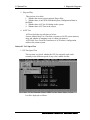
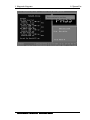
The Diagnostics Screen Explanation......................................................12
Options .....................................................................................................................16
3.3.1
Overview ................................................................................................16
3.3.2
Batch Parameters Configuration ............................................................17
3.3.3
Item’s Parameters Configuration ...........................................................19
3.3.4
Load Batch Parameters...........................................................................20
3.3.5
Save Batch Parameters ...........................................................................21
3.3.6
LOG Parameters Setting.........................................................................21
3.3.7
Specify LOG Viewer ..............................................................................22
3.3.8
Display LOG File ...................................................................................23
3.3.9
LOG Viewer ...........................................................................................23
3.3.10
LOG File Sample ...................................................................................25
3.4
Subtests.....................................................................................................................26
3.5
System Test ..............................................................................................................29
3.6
Memory Test ............................................................................................................34
3.7
Storage ......................................................................................................................40
3.8
Video ........................................................................................................................44
3.9
Communication (COMM) ........................................................................................52
3.10
Peripheral .................................................................................................................53
3.11
Error Codes and description .....................................................................................57
3.12
Quick Test Item List ................................................................................................... i
Chapter 4
4.1
Replacement Procedures
General ................................................................................................................... 4-1
Safety Precautions................................................................................................ 4-2
Safety Precautions................................................................................................ 4-2
Before You Begin ................................................................................................ 4-4
Disassembly Procedures ...................................................................................... 4-5
viii
Satellite/Satellite Pro/L630/L635
Maintenance Manual
Assembly Procedures ........................................................................................... 4-5
Tools and Equipment ........................................................................................... 4-6
Screw Tightening Torque .................................................................................... 4-6
Colors of Screw Shanks ....................................................................................... 4-7
Symbols of Screws on the Computer Body ......................................................... 4-7
Symbol examples ................................................................................................. 4-7
4.2
Battery Pack/PC card/Bridge Media ...................................................................... 4-8
4.2.1
Battery Pack ......................................................................................... 4-8
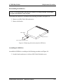
Removing the Battery Pack ................................................................................. 4-8
Installing the Battery Pack ................................................................................... 4-9
4.2.2
Bridge Media ...................................................................................... 4-10
Removing the Bridge Media .............................................................................. 4-10
Installing the Bridge Media ............................................................................... 4-10
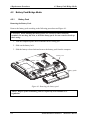
4.3
Memory Module ................................................................................................... 4-11
Removing the Memory Module ......................................................................... 4-11
Installing the Memory Module .......................................................................... 4-12
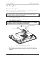
4.4
HDD ..................................................................................................................... 4-13
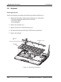
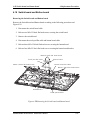
Removing the HDD ........................................................................................... 4-13
Installing the HDD ............................................................................................. 4-15
4.5
ODD Bay Module ................................................................................................ 4-16
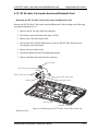
Removing the ODD Bay Module ...................................................................... 4-16
Installing the ODD Bay Module ........................................................................ 4-17
Disassembling the ODD Drive .......................................................................... 4-18
Assembling the ODD Bezel ............................................................................... 4-18
Disassembling the ODD Drive .......................................................................... 4-19
Assembling the ODD Drive ............................................................................... 4-19
4.6
Keyboard .............................................................................................................. 4-20
Removing Keyboard .......................................................................................... 4-20
Installing the Keyboard and RTC battery .......................................................... 4-21
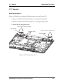
4.7
Wireless LAN Card .............................................................................................. 4-22
Removing the Wireless LAN Card .................................................................... 4-22
Installing the Wireless LAN Card...................................................................... 4-23
Satellite/Satellite Pro/L630/L635
Maintenance Manual
ix
4.8
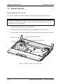
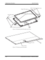
Top Cover ............................................................................................................. 4-24
Installing the Top Cover .................................................................................... 4-25
4.9
Display Assembly ................................................................................................ 4-26
Removing the Display Assembly....................................................................... 4-26
Installing the Display Assembly ........................................................................ 4-27
4.10
System Board ....................................................................................................... 4-28
Removing the System Board ............................................................................. 4-28
Installing the System Board ............................................................................... 4-29
4.11
Thermal module ................................................................................................... 4-30
Remove the Thermal module (for VGA Model) ............................................... 4-30
Installing the thermal module (for VGA Model) ............................................... 4-31
Removing the thermal Module .......................................................................... 4-32
Installing the thermal Module ............................................................................ 4-33
4.12
CPU ...................................................................................................................... 4-34
Removing the CPU ............................................................................................ 4-34
Installing the CPU .............................................................................................. 4-35
4.13
Display Mask........................................................................................................ 4-37
Removing the Display Mask.............................................................................. 4-37
Installing the Display Mask ............................................................................... 4-38
4.14
LCD Module ........................................................................................................ 4-39
Removing the LED module ............................................................................... 4-39
Installing the LCD Module ................................................................................ 4-41
4.15
CCD Board and MIC............................................................................................ 4-42
Removing the CCD Board and MIC .................................................................. 4-42
Installing the CCD Board and MIC ................................................................... 4-42
4.16
Power Button Board ............................................................................................. 4-43
Removing the Power Button Board ................................................................... 4-43
Installing the Power Button Board..................................................................... 4-44
4.17
Speakers ............................................................................................................... 4-45
Removing the Speakers ..................................................................................... 4-45
Installing the Speakers ....................................................................................... 4-46
4.18
x
Switch board and Button board ............................................................................ 4-47
Satellite/Satellite Pro/L630/L635
Maintenance Manual
Removing the Switch board and Button board .................................................. 4-47
Installing the Switch board and Button board ................................................... 4-48
4.19
DC IN cable, Card reader board and Bluetooth Card .......................................... 4-49
Removing the DC IN cable, Card reader board and Bluetooth Card................. 4-49
Installing the DC IN cable, Card reader board and Bluetooth Card .................. 4-50
Satellite/Satellite Pro/L630/L635
Maintenance Manual
xi
Appendices
Appendix A
Handling the LCD Module ........................................................................... A-1
Appendix B
Board Layout .................................................................................................B-1
Appendix C
Keyboard Scan/Character Codes ...................................................................C-1
Appendix D
Key Layout.................................................................................................... D-1
xii
Satellite/Satellite Pro/L630/L635
Maintenance Manual
Chapter 1
Hardware Overview
1 Hardware Overview
ii
Satellite/Satellite Pro/L630/L635
Maintenance Manual
1 Hardware Overview
Chapter 1
Contents
1.1 Features ............................................................................................................................... 5
1.2 System Unit Components ................................................................................................. 12
1.3 2.5-inch HDD .................................................................................................................... 17
1.4 DVD Super Multi (+-R Double Layer)............................................................................. 18
1.5 Blu-Ray Writer.................................................................................................................. 19
1.6 Power Supply .................................................................................................................... 20
1.7 Batteries ............................................................................................................................ 21
1.7.1
Main Battery .......................................................................................... 21
1.7.2
Battery Charging Control ...................................................................... 21
1.7.3
RTC Battery .......................................................................................... 22
Satellite/Satellite Pro/L630/L635
Maintenance Manual
iii
1 Hardware Overview
Figures
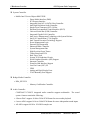
Figure 1-1 ID Parts Description Placement ............................................................................... 9
Figure 1-2 Computer Block Diagram ...................................................................................... 10
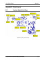
Figure 1-3 System Board Configurations ................................................................................ 11
Figure 1-4 System Unit Block Diagram .................................................................................. 12
Figure 1-5 SATA HDD ........................................................................................................... 17
Figure 1-6 DVD Super Multi Drive ........................................................................................ 18
Figure 1-7 Blu-Ray Writer Drive ............................................................................................ 19
Tables
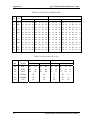
Table 1-1 HDD Specifications ................................................................................................ 17
Table 1-2 DVD Super Multi Drive Specifications .................................................................. 18
Table 1-3 Blu-Ray Writer Drive Specifications ...................................................................... 19
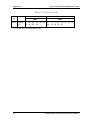
Table 1-4 Battery Specifications ............................................................................................. 21
Table 1-5 Quick/Normal Charging Time ................................................................................ 22
iv
Satellite/Satellite Pro/L630/L635
Maintenance Manual
1.1 Features
1 Hardware Overview
1.1 Features
Toshiba Satellite L630/L635/Satellite Pro L630/L635 is a full size notebook PC based on the
mobile Intel Arrandale Processor, providing high-speed processing capabilities and advanced
features. The computer employs a Lithium Ion battery that allows it to be battery-operated for a
longer period of time. The display uses 13.3-inch HD LED panel, at a resolution of 1366x768.
The uPGA Socket supports BTO/CTO for the CPU so that the system can be designed to suit
your needs.
The computer has the following features:
Processor
CPU is mobile Intel Arrandale Processor:
Intel Core i5 CPU (1066MHz FSB)
Core i5-430M(2.26G, Turbo Boost to 2.53G) Hz
Core i5-450M(2.40G, Turbo Boost to 2.66G) Hz
Core i5-520M(2.40G, Turbo Boost to 2.93G) Hz
Intel Core i3 CPU (1066MHz FSB)
Core i3-330M(2.13G) Hz
Core i3-350M(2.26G) Hz
Intel Pentium CPU (1066MHz FSB)
P6000(1.86G) Hz
Host Bridge System Controller
System Controller: Intel 5 Series Chipset HM55.
Graphics
Intel integrated graphics or M92XTX, Park XT discrete graphics.
Memory
Satellite/Satellite Pro/L630/L635
Maintenance Manual
5
1 Hardware Overview
1.1 Features
The computer has two SO-DIMM slots, which come standard with DDR3-1066MHz
(PC3-8500) memory module. DDR3 is driven at 1.5V. It accepts BTO/CTO for your
memory requirements. It can incorporate up to 8.0GB of main memory.
Using the following sizes of memory modules:
y 1024 MB (128M×64) / DDR3-1066MHz
y 2048 MB (256M×64) / DDR3-1066MHz
y 4096 MB (512M×64) / DDR3-1066MHz
Hard Disk Drive (HDD)
The computer accommodates 2.5-inch 9.5mm height Serial ATA HDD with following
storage capacities:
y 250 GB (9.5mm thick) SATA (5,400rpm)
y 320 GB (9.5mm thick) SATA (5,400rpm)
y 500 GB (9.5mm thick) SATA (5,400rpm)
y 640 GB (9.5mm thick) SATA (5,400rpm)
ODD
The computer accommodates a fixed 12.7mm ODD with one of following types:
y Tray Type DVD Super Multi +-R Double Layer drive
y Tray Type DVD Super Multi +-R Double Layer with Label Flash™ drive
y Tray Type Blue-Ray Combo BD-ROM with Label Flash™ drive
y Tray Type Blue-Ray Writer BD-RE with Label Flash™ drive
Display
LCD displays come in the following types at resolution 1366x768:
y 13.3” WXGA HD 1366x768 CSV LED display
On-Board LAN (BTO)
The internal LAN supports 10/100Mbit or 1Gbit Ethernet, enabling connection to a LAN
at up to 1Gbps. It supports Wake-up on LAN from S3/S4/S5 and PXE boot support.
This internal LAN has RJ45 jack to directly accommodate a LAN cable.
6
Satellite/Satellite Pro/L630/L635
Maintenance Manual
1.1 Features
1 Hardware Overview
Wireless LAN (BTO)
The internal Mini Card slot supports IEEE802.11bg (MOW) / IEEE802.11abg (MOW) /
IEEE802.11abgn (MOW) / IEEE802.11bgn (MOW) / IEEE802.11bg w/BT /
IEEE802.11bgn w/BT cards. The Antenna has two wires antenna support for BTO.
Sound System
CONEXANT CX20671 integrated audio controller supports multimedia. The sound
system contains the following:
y Stereo speakers
y Headphone jack
y Internal microphone
y External microphone jack
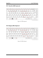
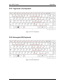
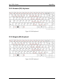
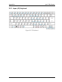
Keyboard (BTO)
33 kinds’ countries keyboard, which is TOSHIBA 2010 New A4 with numeric keypad
flat one.
Toshiba Touch Pad
Normal Wide Touch Pad with ON / OFF mechanical button.
Bluetooth (BTO)
Bluetooth wireless technology eliminates the need for cables between electronic device
such as desktop computer, printer and mobile phone.
eSATA / USB Combo Port
This product has one eSATA / USB Combo port, which allows device connection
through either eSATA or USB signals of eSATA / USB Combo Port.
USB Port
The computer has two USB 2.0 ports. It is supported to daisy-chain a maximum of 127
USB devices. The serial data transfer rate is 480Mbps, 12Mbps and 1.5Mbps. These
ports support PnP installation and hot plugging.
Satellite/Satellite Pro/L630/L635
Maintenance Manual
7
1 Hardware Overview
1.1 Features
RGB External Monitor Port
A 15-pin external monitor port is provided, through which the computer automatically
recognizes an external VESA DDC 2B compatible monitor.
HDMI Out Port (BTO)
A HDMI monitor can be connected to HDMI Out Port on the computer.
Bridge Media Slot
This slot is for your memory card requirements like SD, Mini-SD, Micro-SD, SDHC,
SDXC, MMC, Memory Stick and Memory Stick Pro Cards to provide memory card read
on your computer.
Webcam (BTO)
The computer has an internal camera. It supports VGA (640x480) without Macro
module, which also equips with Internal MIC.
Battery (BTO)
The computer has a removable 3/6/12 Cell Lithium Ion battery pack and an internal RTC
battery (rechargeable).
8
Satellite/Satellite Pro/L630/L635
Maintenance Manual
1.1 Features
1 Hardware Overview
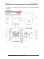
Figures 1-1/1-2/1-3 and 1-4 show the computer and its system unit configuration,
respectively.
Figure 1-1 ID Parts Description Placement
Satellite/Satellite Pro/L630/L635
Maintenance Manual
9
1 Hardware Overview
1.1 Features
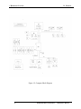
Figure 1-2 Computer Block Diagram
10
Satellite/Satellite Pro/L630/L635
Maintenance Manual
1.1 Features
1 Hardware Overview
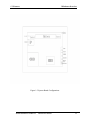
Figure 1-3 System Board Configurations
Satellite/Satellite Pro/L630/L635
Maintenance Manual
11
1 Hardware Overview
1B1.2 System Unit Components
1.2 System Unit Components
Figure 1-4 is Block Diagram of the System Unit.
Figure 1-4 System Unit Block Diagram
12
Satellite/Satellite Pro/L630/L635
Maintenance Manual
1.2 System Unit Components
1 Hardware Overview
The system unit of the computer consists of the following components:
Processor: Mobile Intel Arrandale Processor.
y Intel Core i5 Processor (FSB, 1066MHz)
− Core Speed: 2.26/2.40 GHz
− System Bus: 1066 MHz
− On-Die Level 2 Cache: 3 MB
y Intel Core i3 Processor (FSB, 1066MHz)
− Core Speed: 2.13/2.26 GHz
− System Bus: 1066 MHz
− On-Die Level 2 Cache: 3 MB
y Intel Pentium Processor (FSB, 1066MHz)
− Core Speed: 1.86 GHz
− System Bus: 1066 MHz
− On-Die Level 2 Cache: 3 MB
Memory: Two expansion memory slots are provided. They can hold 1.0/2.0/4.0GB memory
modules available as options to grow up to 8.0GB.
y PC3-8500 (1066MHz) DDR3 SDRAM supported
y 1024/2048/4096MB modules supported
− 1024 MB (128M x 64)
− 2048 MB (256M x 64)
− 4096 MB (512M x 64)
y DDR3 1.5 volt operation
y No parity bit
y 64-bit data transfer
BIOS ROM (Flash EEPROM)
y 32Mb x 1 chip (4096KB flash parts)
−
−
−
−
−
−
NvStorage Size : 64K
NvStorage Free Space : 63K
FV00 Size : 992K
FV00 Free Space : 176K
FV01 Size : 384K
FV01 Free Space : 68K
Satellite/Satellite Pro/L630/L635
Maintenance Manual
13
1 Hardware Overview
1B1.2 System Unit Components
System Controller
y Mobile Intel 5 Series Chipset HM55 PCH
−
−
−
−
−
−
−
−
−
−
−
−
−
−
−
−
−
−
−
−
−
−
−
−
−
−
Direct Media Interface (DMI)
PCI Express Interface
Integrated Serial ATA (SATA) Host Controller
Intel High Definition Audio Controller
Simple Serial Transport (SST) 1.0 Bus
Platform Environmental Control Interface (PECI)
Universal Serial Bus (USB) Controller
Integrated Gigabit LAN Controller
Intel Active Management Technology with System Defense
Intel I/O Virtualization (VT-d) Support
Intel Trusted Execution Technology Support
Power Management Logic
External Glue Integration
Enhanced DMA Controller
System Management Bus
High Precision Event Timers
Timers Based on 82C54
Real-Time Clock
System TCO Reduction Circuits
Serial Peripheral Interface (SPI) Support
Interrupt Controller
Firmware Hub Interface Support
Low Pin Count (LPC) I/F
GPIO
Analog and Digit Display Ports
JTAG Boundary Scan Support
Bridge Media Controller
y REA_RTS5159
− Memory Card Reader Controller
Audio Controller
CONEXANT CX20671 integrated audio controller supports multimedia. The sound
system features contain the following:
y 4 Stereo DACs support 16-bit to 24-bit PCM format for stereo audio playback
y 6 stereo ADCs support 16-bit to 24-bit PCM format for stereo independent sound inputs
y All ADCs support 44.1K to 192.0K Hz sample rate
14
Satellite/Satellite Pro/L630/L635
Maintenance Manual
1.2 System Unit Components
1 Hardware Overview
y Digital microphone interface with internal MIC boost supporting
y Jack sense detects up to 4 jacks using only one sense pin
y Digital Mixer
y +3.3V analog and I/O operation; uses Vaux for power management modes
y Audio Director for Headphone and Internal Speakers Redirection
y Smart Audio GUI - advanced audio control
KBC/EC (Keyboard Controller/Embedded Controller)
A KBC WINBOND NPCE781LA0DX chip is used to serve as KBC/EC and Super IO:
y KBC
− Scan controller function
− Interface controller function
y EC
−
−
−
−
−
−
−
−
−
−
−
Power supply sequence control
Overheat shutdown support
LED control
Beep control
Device ON/OFF
Cooling fan speed control
Universal I/O port
Battery capacity check
Flash memory reprogramming function
EC access interface
I2C communication control
Battery EEPROM
y 24C02 equivalent (128 words x 16 bits, I2C interface) integrated in battery pack
− Storing records of battery use
Clock Generator
y ICS ICS9LPRS3197
− Generating the clock signal required for the system
LAN Controller
Satellite/Satellite Pro/L630/L635
Maintenance Manual
15
1 Hardware Overview
1B1.2 System Unit Components
y Atheros AR8152 / AR8151 - 10/100Mbit / 1Gbit
−
−
−
−
−
−
−
−
IEEE802.3 10BASE-T/100BASE-TX physical layer interface
IEEE 802.3u Auto-Negotiation support
Digital Adaptive Equalization control
10BASE-T auto-polarity correction
LAN Connect interface
Automatic detection of “unplugged mode”
Remote boot (PXE 2.1)
Smart power down when link is not detected
Wireless LAN Controller
y Support following 3 kinds of mini PCI wireless LAN cards
− IEEE 802.11bg
− IEEE 802.11ag
− IEEE 802.11agn
y Data Rate
− IEEE 802.11bg: Standard 54M bps
− IEEE 802.11ag: Standard 54M bps
− IEEE 802.11agn: Standard 130M bps
y Frequency Channel
− IEEE802.11bg: 2.4GHz
− IEEE802.11ag: 2.4GHz / 5.4GHz
− IEEE802.11agn: 2.4GHz / 5.4GHz
16
Satellite/Satellite Pro/L630/L635
Maintenance Manual
2B1.3 2.5-inch HDD
1 Hardware Overview
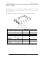
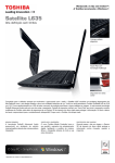
1.3 2.5-inch HDD
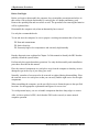
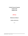
The computer contains an extremely low-profile, lightweight and high-performance HDD.
The HDD incorporates 9.5 mm height magnetic disk and mini-Winchester type magnetic
heads. The HDD interface conforms to Serial ATA. Storage capacities supported are 250,
320, 500 & 640GB.
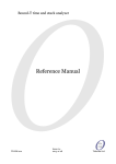
The HDD is shown in Figure 1-5 and some of its specifications are listed in Table 1-1.
Figure 1-5 SATA HDD
Table 1-1 HDD Specifications
Item
Capacity (GB)
Rotational Speed (RPM)
Height
User Data Sectors
Bytes / Sector
Specifications
250 GB
320 GB
500 GB
5400 rpm
5400 rpm
5400 rpm
9.5 mm
9.5 mm
9.5 mm
488,397,168
625,142,448
976,773,168
512
512
512
Item
Capacity (GB)
Rotational Speed (RPM)
Height
User Data Sectors
Bytes / Sector
Specifications
640 GB
-
-
5400 rpm
-
-
9.5 mm
-
-
1,250,263,728
-
-
512
-
-
Satellite/Satellite Pro/L630/L635
Maintenance Manual
17
1 Hardware Overview
3B1.4 DVD Super Multi (+-R Double Layer)
1.4 DVD Super Multi (+-R Double Layer)
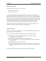
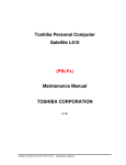
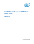
The DVD Super Multi drive accepts 12-cm (4.72-inch) and 8-cm (3.15-inch) discs. At
maximum, the drive can play back DVD-ROM at 8x speed, read CD-ROM at 24x speed, and
write CD-R at 24x speed, CD-RW at 4x speed, US CD-RW at 24x speed, High Speed CDRW at 10x speed, DVD-R at 8x speed, DVD-RW at 6x speed, DVD-R DL at 6x speed,
DVD+R at 8x speed, DVD+RW at 8x speed, DVD+R DL at 6x speed and DVD-RAM at 5x
speed.
DVD Super Multi Drive is shown in Figure 1-6 and its specifications are listed in Table 1-2.
Figure 1-6 DVD Super Multi Drive
Table 1-2 DVD Super Multi Drive Specifications
Item
Data Transfer Rate
(Mbytes/s)
DVD-ROM mode
33.3 (U-DMA transfer mode 2)
16.7 (PIO mode 4, Multiword DMA mode 2)
Access Time (ms)
Average Random
Access
Data Buffer Size
(Mbytes)
Formats Supported
CD-ROM mode
130 ms
130 ms
2MB
DVD:
DVD-VIDEO, DVD-ROM, DVD-R, DVD-RW, DVD-RAM,
DVD+R, DVD+-R (Double Layer), DVD+RW.
CD:
CD-DA, CD-ROM, CD-R, CD-RW, CD-ROMXA, Photo CD (MultiSession), Video CD, CD-Extra (CD+), CD-Text.
18
Satellite/Satellite Pro/L630/L635
Maintenance Manual
Fehler! Verweisquelle konnte nicht gefunden werden.
1 Hardware Overview
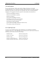
1.5 Blu-Ray Writer
Blu-Ray Writer drive accepts 12-cm (4.72-inch) or 8-cm (3.15-inch) discs. At maximum, it
can read CD-ROM at 24x speed, play DVD-ROM at 8x speed, read BD-ROM Video at 1.6x
speed, BD-ROM Data at 6x speed, and write CD-R at 24x speed, CD-RW at 4x speed, High
Speed CD-RW at 10x speed, Ultra Speed CD-RW at 16x speed, DVD-R at 8x speed, DVDRW at 6x speed, DVD-R DL at 4x speed, DVD+R at 8x speed, DVD+RW at 8x speed,
DVD+R DL at 4x speed, DVD-RAM at 5x speed, BD-R at 6x speed, and BD-RE at 2x speed.
Blu-Ray Writer drive is shown in Figure 1-7 and its specifications are listed in Table 1-3.
Figure 1-7 Blu-Ray Writer Drive
Table 1-3 Blu-Ray Writer Drive Specifications
Item
SATA Interface
BD-ROM Mode
DVD-ROM Mode
CD-ROM Mode
190 ms
180 ms
150 MB/s
Average Random
Access Time
300 ms
Buffer Memory Size
2MB
(Mbytes)
Formats Supported
BD:
BD-ROM, BD-R, BD-RE.
DVD
DVD-VIDEO, DVD-ROM, DVD-R, DVD-RW, DVD-R DL, DVD-RAM,
DVD+R, DVD+RW, DVD+R DL.
CD:
CD-DA, CD-ROM, CD-R, CD-RW, CD-ROMXA, Photo CD (MultiSession), Video CD, CD-Extra (CD+), CD-Text Hybrid SACD.
Satellite/Satellite Pro/L630/L635
Maintenance Manual
19
1 Hardware Overview
6B1.7 Batteries
1.6 Power Supply
The power supply unit provides many different voltages for the system board and performs the
following functions:
1. Power input monitor
y Checks whether the DC power supply (AC adapter) is connected to the computer.
y Checks whether the battery pack is connected to the computer.
y Monitors the DC power supply input voltage (AC Adapter output voltage).
2. Power supply's internal control
y Turns on and off the battery pack charging power supply.
y Issues a charging current instruction to the PWM control IC of the battery pack charging
power supply.
y Controls the supply of DC power supply input (AC Adapter output) to the power supply
unit.
y Controls the supply of power to the system block (load/logic circuit side).
y Controls forced shutdown if the power supply malfunctions.
3. Logic circuit control
y Instructs the gate array to enable/disable tuning the power on.
y Controls power-on/off operation.
4. Status display
y Turns on the Power LED (in White).
y Battery indicator (in White, Amber or Amber Flash).
5. External interface
y Performs communication through the I2C bus (via the internal EC/KBC).
y Transfers the power supply operation mode.
6. Output monitor
y Monitors the voltage output to the system block (load/logic circuit side).
y Monitors the voltage, over voltage, input/output current of the battery pack.
y Monitors the internal temperature of the battery pack.
y Monitors the supply voltage from the AC adapter.
20
Satellite/Satellite Pro/L630/L635
Maintenance Manual
4B1.5 Blu-Ray Writer
Blu-Ray Writer drive accepts 12-cm (4.72-inch) or 8-cm (3.15-inch) discs. At maximum, it can
read CD-ROM at 24x speed, play DVD-ROM at 8x speed, read BD-ROM Video at 1.6x speed,
BD-ROM Data at 6x speed, and write CD-R at 24x speed, CD-RW at 4x speed, High Speed CDRW at 10x speed, Ultra Speed CD-RW at 16x speed, DVD-R at 8x speed, DVD-RW at 6x speed,
DVD-R DL at 4x speed, DVD+R at 8x speed, DVD+RW at 8x speed, DVD+R DL at 4x speed,
DVD-RAM at 5x speed, BD-R at 6x speed, and BD-RE at 2x speed.
Blu-Ray Writer drive is shown in Figure 1-7 and its specifications are listed in Table 1-3.
Figure 1-7 Blu-Ray Writer Drive
Table 1-3 Blu-Ray Writer Drive Specifications
1.7 Batteries
The computer has the following 2 types of batteries:
Main Battery Pack
Real Time Clock (RTC) Battery
Table 1-4 lists the specifications of these batteries.
Table 1-4 Battery Specifications
Battery Type
Material
Output voltage
Capacity
3 Cell
Lithium Ion
10.8 V
2000 mAh
6 Cell
Lithium Ion
10.8 V
Main Battery Pack
Satellite/Satellite Pro/L630/L635
Maintenance Manual
4400 mAh
5600 mAh
21
1 Hardware Overview
6B1.7 Batteries
12 Cell
RTC Battery
1.7.1
Lithium Ion
10.8 V
9000 mAh
Lithium Ion
3.0 V
14 mAh
Main Battery
The main battery pack serves as the computer's main power source when the AC adapter
is not attached. The main battery maintains the state of the computer so that it can
resume it.
1.7.2
Battery Charging Control
Battery charging is controlled by WINBOND NPCE781L. When AC adapter and battery
pack are attached to the computer, the NPCE781L controls the charge on/off state and
detects a full charge.
Battery Charge
When the AC adapter is attached, the battery is charged by off-state charge when the
system is powered off or by on-state charge when it is powered on.
Table 1-5 Quick/Normal Charging Time
State
Charge Time
Off-State Charge
3/6/12 Cell
About 4 hours max
On-State Charge
3/6/12 Cell
About 4~10 hours max
NOTE: The time required for normal charge depends on the power consumption by the
system. Using the fluorescent lamp and frequently accessing the disk consume much
power and lengthen the charge time.
Any of the following cases stops battery charge:
22
1.
The battery becomes fully charged.
2.
The AC adapter or battery pack is removed.
Satellite/Satellite Pro/L630/L635
Maintenance Manual
6B1.7 Batteries
3.
1 Hardware Overview
The battery or AC adapter voltage is abnormal.
Detection of full charge
A full charge is detected only when the battery is being charged by quick or normal
charge. A full charge is detected when either of the following conditions is met:
1.7.3
1.
The current in the battery charging circuit drops below the predetermined
value.
2.
The charging time exceeds the fixed limit.
RTC Battery
The RTC battery provides power to keep the current date, time and other system
information in memory while the computer is turned off.
Satellite/Satellite Pro/L630/L635
Maintenance Manual
23
2 Troubleshooting
2
概要
Chapter 2
Troubleshooting
Satellite/Satellite Pro/L630/L635
Maintenance Manual
2-i
2 Troubleshooting
Chapter 2
Contents
2.1 Outline .................................................................................................................... 2-1 2.2 Basic Flowchart ...................................................................................................... 2-2 2.3 Power Supply ......................................................................................................... 2-6 Procedure 1 Power Icon Check ....................................................................... 2-6 Procedure 2 Connection Check....................................................................... 2-7 Procedure 3 Replacement Check .................................................................... 2-7 2.4 System Board ......................................................................................................... 2-8 Procedure 1 Message Check ........................................................................... 2-8 Procedure 2 Test Program Check .................................................................... 2-9 Procedure 3 Replacement Check .................................................................... 2-9 2.5 HDD ..................................................................................................................... 2-10 Procedure 1 Message Check ......................................................................... 2-10 Procedure 2 Partition Check ......................................................................... 2-10 Procedure 3 Format Check............................................................................ 2-11 Procedure 4 Test Program Check .................................................................. 2-11 Procedure 5 Connector Check and Replacement Check............................... 2-13 2.6 Keyboard .............................................................................................................. 2-14 Procedure 1 Test Program Check .................................................................. 2-14 Procedure 2 Connector Check and Replacement Check............................... 2-14 2.7 Display ................................................................................................................. 2-15 Procedure 1 External Monitor Check ........................................................... 2-15 Procedure 2 Test Program Check .................................................................. 2-15 Procedure 3 Connector Check and Replacement Check............................... 2-15 2.8 ODD (Optical Disk Drive) ................................................................................... 2-17 Procedure 1 ODD Cleaning Check ............................................................... 2-17 Procedure 2 Test Program Check .................................................................. 2-17 Procedure 3 Connector Check and Replacement Check............................... 2-17 2.9 LAN ...................................................................................................................... 2-19 Procedure 1 Test Program Check .................................................................. 2-19 Procedure 2 Connector Check and Replacement Check............................... 2-19 2-ii
Satellite/Satellite Pro/L630/L635
Maintenance Manual
2 Troubleshooting
2.10 Audio Test ............................................................................................................. 2-20 Procedure 1 Test Program Check .................................................................. 2-20 Procedure 2 Connector Check and Replacement Check ............................... 2-20 2.11 Cooling Module .................................................................................................... 2-21 Procedure 1 Test Program Check .................................................................. 2-21 Procedure 2 Connector Check and Replacement Check ............................... 2-21 Figures
Figure 2-1 Basic Flowchart (1/2) ..................................................................................... 2-3 Tables
Table 2- 1
HDD Error Code and Status ......................................................................... 2-12 Satellite/Satellite Pro/L630/L635
Maintenance Manual
2-iii
2.1 Outline
2 Troubleshooting
2.1 Outline
This chapter describes the fault diagnosis procedures for field replaceable units (FRUs) in the
computer.
The FRUs covered here are as follows:
1. System board
2. HDD
4. Display
5. ODD drive
7. Speaker
8. Cooling module
3. Keyboard
6. LAN
See Chapter 4 for the procedures to replace FRUs and Chapter 3 for the procedures to use test
programs.
The following tools are required to perform the diagnostic procedures:
1. Diagnostics (maintenance test program) disk
2. Screwdrivers (2 mm, 2.5 mm)
3. Cleaning disk kit (for ODD drive cleaning)
4. Bootable CD
5. Multi-meter
6. External monitor
7. Headphone
8. Microphone
9. A-BEX TEST DVD
10. Music CD
11. DVD TSD-1 (TOSHIBA EMI DVD Test Media)
2-1
Satellite/Satellite Pro/L630/L635
Maintenance Manual
2 Troubleshooting
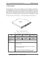
2.2 Basic Flowchart
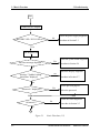
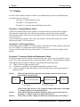
2.2 Basic Flowchart
The basic flowchart in Figure 2-1 serves as a guide for identifying a possibly faulty FRU.
Before going through the diagnostic flowchart steps, verify the following:
Ask the user if a password has been registered and, if so, ask him or her to enter
the password. If the user has forgotten the system password, use a jump wire to
make a short circuit on M/B B500 location, then turn the computer power on.
When booted, the computer overrides password protection and automatically
erases the current password.
Make sure the Windows® 7 Home Edition has been installed on the HDD. Any
other operating system can cause the computer to malfunction.
Make sure any piece of optional equipment has been installed.
Satellite/Satellite Pro/L630/L635
Maintenance Manual
2-2
2.2 Basic Flowchart
2 Troubleshooting
Start
Connect the AC Adapter
Follow the power supply diagnostic
No
BATTERY LED / DC IN LED on ??
Procedure in Section 2.3
Yes
Turn the power on.
Follow the system board diagnostic
Yes
Any error message displayed ??
Procedure in Section 2.4
No
Follow the display diagnostic
No
Message "Toshiba Leading
Innovation "displayed
Procedure in Section 2.7
Yes
See the previous page to
Yes
"Password=" displayed ??
Delete the password.
No
Follow the HDD diagnostic
OS started ??
No
Procedure in Section 2.5
Yes
1
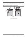
Figure 2-1
2-3
Basic Flowchart (1/2)
Satellite/Satellite Pro/L630/L635
Maintenance Manual
2 Troubleshooting
2.2 Basic Flowchart
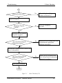
1
Keyboard works well ??
No
Follow the keyboard diagnostic
procedure in Section 2.6
No
Follow the diagnostic
procedure
Yes
Identify the test resulting in the error
and perform the appropriate
diagnostic procedures
Yes
Identify the test resulting in the
error and perform the appropriate
diagnostic procedures
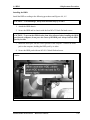
Insert Bootable CD into ODD or Bootable USB
Memory into USB port.
Diagnostic Program
Loaded??
Yes
Perform each test with the
diagnostic program.
Any error detected by the
diagnostic program ??
No
Perform the continuous test to check if the
error is intermittent.
Any error detected by the
diagnostic program??
No
The system is normal.
END
Figure 2-1
Satellite/Satellite Pro/L630/L635
Basic Flowchart (2/2)
Maintenance Manual
2-4
2.2 Basic Flowchart
2 Troubleshooting
If the diagnostic program cannot detect an error, the error may be intermittent. Run the
continuous test program repeatedly to isolate the problem. Check the log utilities function to
confirm which diagnostic test detected the error, then perform the appropriate troubleshooting
procedures as follows:
1. If an error is detected by the System test, Memory test, Async test, Printer test, Sound
test, or Real Timer test, follow the system board troubleshooting procedures in Section
2.4.
2. If an error is detected by the Hard Disk test, follow the HDD troubleshooting procedures
in Section 2.5.
3. If an error is detected by the Keyboard test, follow the keyboard troubleshooting
procedures in Section 2.6.
4. If an error is detected by the Display test, follow the display troubleshooting procedures
in Section 2.7.
5. If an error is detected by the ODD test, follow the ODD troubleshooting procedures in
Section 2.8.
6. If an error is detected by the LAN test, follow the LAN troubleshooting procedures in
section 2.9.
7. If an error is detected by the Speaker test, follow the Speaker troubleshooting procedures
in section 2.10.
8. If an error is detected by the Fan On/Off test, follow the cooling module troubleshooting
procedures in Section 2.11.
2-5
Satellite/Satellite Pro/L630/L635
Maintenance Manual
2 Troubleshooting
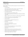
2.3 Power Supply
2.3 Power Supply
The power supply in the computer controls many functions and components. To check if the
power supply is defective or malfunctioning, follow the troubleshooting procedures below as
instructed.
Procedure 1
Power Icon Check
Procedure 2
Connection Check
Procedure 3
Replacement Check
Procedure 1 Power Icon Check
The following LED indicates the power supply status:
Battery LED/ DC IN LED
The power supply controller displays the power supply status through the Battery LED / DC
IN LEDs as in the tables below.
Battery LED / DC IN LED
Power supply status
On in Green
AC Adaptor is plugged or Battery is fully charged
On in Amber
Battery is being charged from AC Adaptor
Blinking in Amber
Critical low battery while driving the computer
Off
Else
If the Battery LED / DC IN LED off, follow the steps below:
1. Remove the battery pack and the AC adapter to shut off power supply to the computer.
2. Attach the battery pack and AC adapter back again.
Check 1
Make sure the Battery LED / DC IN LED goes on. If it does not, go to
Procedure 2.
Check 2
Make sure the computer is able to be powered without AC adaptor supply, if it
does not, go to Procedure 3.
Satellite/Satellite Pro/L630/L635
Maintenance Manual
2-6
2.3 Power Supply
2 Troubleshooting
Procedure 2 Connection Check
Power is supplied to the system board as illustrated below:
System board
AC
adaptor
AC power cord
AC adaptor cord
Battery pack
Follow the steps below to check whether each connector has been connected correctly:
Check 1
Make sure the AC adaptor and AC power cord have been firmly plugged
into the DC IN socket and wall outlet respectively. When they have been
connected correctly, perform Check 2.
Check 2
Connect a new AC adaptor and AC power cord.
If the Battery LED / DC IN LED does not go on, go to Procedure 3.
If the Battery LED / DC IN LED does not go on in Amber, perform Check 3.
Check 3
Make sure the battery pack has been correctly installed in the computer
and it is not fully charged. If the battery LED does not go on in Amber
while the battery pack has been installed correctly, go to Procedure 3.
Procedure 3 Replacement Check
The battery pack, system board or CPU may be faulty. Disassemble the computer according
to Chapter 4 and follow the steps below:
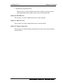
Check 1
Check 2
Check 3
2-7
Replace the battery pack with a new one, if the battery pack is still not
working properly, perform check 2.
Replace the system board with a new one, if the battery pack is still not
working properly, perform Check 3.
Replace the CPU with a new one.
Satellite/Satellite Pro/L630/L635
Maintenance Manual
2 Troubleshooting
2.4 System Board
2.4 System Board
To check if the system board is defective or malfunctioning, follow the troubleshooting
procedures below as instructed.
Procedure 1 Message Check
Procedure 2 Test Program Check
Procedure 3 Replacement Check
Procedure 1 Message Check
When the power is turned on, the system performs the self-diagnostic Power On Self Test (POST)
embedded in the BIOS ROM. The POST tests and initializes each IC on the system board.
If an error message appears on the display, perform Check 1.
If there is no error message, go to Procedure 2.
If FREE-DOS or Windows 7 Home Edition is loaded normally, go to Procedure
3.
Check 1
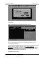
If the following error message is displayed on the screen, press the F1 key as
prompted. These errors occur when the system configuration preserved in the
RTC memory (generally called CMOS memory) does not match the actual
configuration or when the data is lost.
If you press the F1 key as prompted by the message, the TSETUP screen
appears to set the system configuration. If the error message appears
frequently when the power is turned on, replace the RTC battery. If any other
error message is displayed, perform Check 2.
*** Bad RTC battery ***
Check system. Then press [F1] key
Check 2
If the following error message is displayed on the screen, press any key as
prompted by the message.
The error message appears when either data stored in RAM to be resumed is
lost because the battery has been exhausted or the system board is faulty.
*** Resume failure and press any key to continue ***
Satellite/Satellite Pro/L630/L635
Maintenance Manual
2-8
2.4 System Board
2 Troubleshooting
Procedure 2 Test Program Check
The maintenance test program contains several programs for diagnosing the system board and
CPU. Execute the following test programs using the procedures described in Chapter 3.
1. System test
2. Memory test
3. Keyboard test
4. Display test
5. Hard Disk test
6. Mouse test
7. ODD test
8. Sound test
9. LAN test
If an error is detected during these tests, go to Procedure 3.
Procedure 3 Replacement Check
The system board, memory, or CPU may be defective. Disassemble the computer following the
steps described in Chapter 4 and replace the system board, memory module or CPU with a new
one.
2-9
Satellite/Satellite Pro/L630/L635
Maintenance Manual
2 Troubleshooting
2.5 HDD
2.5 HDD
To check if the 9.5mm HDD is defective or malfunctioning, follow the troubleshooting
procedures below as instructed.
Procedure 1 Message Check
Procedure 2 Partition Check
Procedure 3 Format Check
Procedure 4 Test Program Check
Procedure 5 Connector Check and Replacement Check
CAUTION: The contents of the HDD will be erased when the HDD diagnostic test or
formatting is executed. Save the required contents of the HDD to floppy disks or other
storage drive in advance.
Procedure 1 Message Check
When the computer's HDD does not function properly, some of the following error messages
may appear on the display. Follow the steps below to check the HDD.
Check 1
If either of the following messages appears, go to Procedure 2. If the following
messages do not appear, perform Check 2.
Insert system disk in drive
Press any key when ready .....
or
Non-System disk or disk error
Replace and press any key
Check 2
Check SETUP to see if the Hard Disk option has been set to “Not used”. If so,
choose another setting and restart the computer. If the problem persists, go to
Procedure 2.
Procedure 2 Partition Check
Boot from the DOS system. Perform the following checks:
Check 1
Type C: and press the Enter key. If you cannot change to drive C, perform
Check 2. If you can change to drive C, perform Check 3.
Check 2
Type FDISK and press the Enter key. Choose “Display partition information”
from the FDISK menu. If drive C is listed, perform Check 3. If drive C is not
listed, return to the FDISK menu and choose the option to create a DOS
Satellite/Satellite Pro/L630/L635
Maintenance Manual
2-10
2.5 HDD
2 Troubleshooting
partition on drive C. Then restart the computer.. If the problem persists, go
to Procedure 3.
Check 3
If drive C is listed as active in the FDISK menu, perform Check 4. If drive C
is not listed as active, return to the FDISK menu and choose the option to set
the active partition for drive C. Then restart the computer. If the problem
persists, perform Check 4.
Check 4
Enter DIR C: and press the Enter key. If the following message is displayed,
go to Procedure 3. If contents of drive C are listed on the display, perform
Check 5.
Invalid media type reading drive C
Abort, Retry, Fail?
Check 5
Use the SYS command in the DOS system to install system files.
If the following message appears on the display, the system files have been
transferred to the HDD. Restart the computer. If the problem persists, go to
Procedure 3.
System transferred
NOTE: If the computer is running Windows 7 Home edition and the hard disk capacity is
more than 512 MB, the FDISK program will ask if you need support for a partition larger
than 2 GB. Select Y for large partition support; however, be sure to read the precaution
regarding access by other operating systems.
Procedure 3 Format Check
The 2.5-inch HDD is formatted using the low-level format program and the FREE-DOS
FORMAT program. Using these programs, follow the steps below to format the HDD.
Check 1
Enter FORMAT C:/S/U to format the HDD and transfer system files. If the
following message appears on the display, the HDD has been formatted.
Format complete
If you cannot format the HDD using the test program, go to Procedure 4.
Procedure 4 Test Program Check
Run the HDD test program stored on the maintenance test program disk for all test items. See
Chapter 3 for details on how to use the test program.
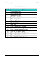
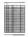
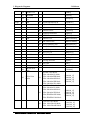
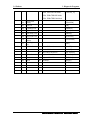
If an error is detected during the HDD test, an error code and status will be displayed. The error
codes and their status names are listed in Table 2-1. If an error code is not generated and the
problem still exists, go to Procedure 5.
2-11
Satellite/Satellite Pro/L630/L635
Maintenance Manual
2 Troubleshooting
2.5 HDD
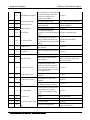
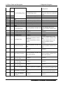
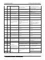
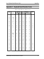
Table 2- 1 HDD Error Code and Status
Code
1
2
3
4
5
6
7
9
10
11
12
13
14
15
16
Status
Get Parameter Fail !
Read Old Data Error
Write Pattern Error
Read Back Data Error
Data Compare Error
Restore Data Error
Read Verify Error
Seek Error
Disk Controller Self Test Failed
Disk Controller Test unexpected interrupt Failed
Disk Controller action Test Failed
Disk dos not support SMART
Disk read attribute threshold error
Disk read attribute value error
Disk SMART attribute value error
Satellite/Satellite Pro/L630/L635
Maintenance Manual
2-12
2.5 HDD
2 Troubleshooting
Procedure 5 Connector Check and Replacement Check
The HDD, system board or CPU may be faulty. Disassemble the computer following the steps
described in Chapter 4 and perform the following checks:
Check 1
Make sure the following connectors have been firmly connected to the HDD,
system board and CPU.
HDD
System board
CPU
If any connector is loose or off, reconnect it firmly and return to Procedure 1.
If there is still an error, perform Check 2.
Check 2
The HDD may be damaged. Replace it with a new one following the
disassembling instructions in Chapter 4. If the problem persists, perform
Check 3.
Check 3
The System board may be damaged. Replace it with a new one following the
disassembling instructions in Chapter 4. If the problem persists, perform
Check 4.
Check 4
The CPU may be damaged. Replace it with a new one following the
disassembling instructions in Chapter 4.
2-13
Satellite/Satellite Pro/L630/L635
Maintenance Manual
2 Troubleshooting
2.6 Keyboard
2.6 Keyboard
To check if the computer’s keyboard is defective or malfunctioning, follow the troubleshooting
procedures below as instructed.
Procedure 1 Test Program Check
Procedure 2 Connector Check and Replacement Check
Procedure 1 Test Program Check
Execute the Keyboard test available as part of the maintenance test program. See Chapter 3 for
information on how to perform the test.
If an error is detected in the test, go to Procedure 2. If no error is detected, the keyboard itself is
normal.
Procedure 2 Connector Check and Replacement Check
The keyboard or system board may be disconnected or faulty. Disassemble the computer
following the steps described in Chapter 4 and perform the following checks:
Check 1
Make sure the keyboard cable has been firmly connected to the system board.
Keyboard
System board
CPU
If the cable is loose or off, reconnect it firmly and return to Procedure 1. If
there is still an error, perform Check 2.
Check 2
The keyboard may be faulty. Replace it with a new one following the
instructions in Chapter 4. If the problem persists, perform Check 3.
Check 3
The System board may be faulty. Replace it with a new one following the
instructions in Chapter 4. If the keyboard is still not functioning properly,
perform Check 4.
The memory may be defective. Replace the memory module with a new one
following the steps described in Chapter 4. If the problem persists, perform
Check 5.
Check 4
Check 5
The CPU may be faulty. Disassemble the computer following the steps
described in Chapter 4 and replace the CPU with a new one.
Satellite/Satellite Pro/L630/L635
Maintenance Manual
2-14
2.7 Display
2 Troubleshooting
2.7 Display
To check if the computer’s display is defective or malfunctioning, follow the troubleshooting
procedures below as instructed.
Procedure 1 External Monitor Check
Procedure 2 Test Program Check
Procedure 3 Connector Check and Replacement Check
Procedure 1 External Monitor Check
Connect an external monitor to the computer's external monitor port, then boot the computer.
The computer automatically detects the external monitor even if resume mode is enabled.
If the external monitor works correctly, the internal LCD, LCD/FL cable, or FL may be faulty.
Go to Procedure 3.
If the external monitor appears to have the same problem as the internal monitor, the system
board may be faulty. Go to Procedure 2.
Procedure 2 Test Program Check
Insert the diagnostics bootable CD in the computer's CD ROM, turn on the computer and run the
test. See Chapter 3 for information on how to perform the test.
If an error is detected in the test, go to Procedure 3. If no error is detected, the display itself is
normal.
Procedure 3 Connector Check and Replacement Check
The display unit has an LCD module, Fluorescent lamp (FL), panel close switch and FL inverter
board. Any of the components or their connections may be defective. Disassemble the computer
following the steps described in Chapter 4, then perform the following checks:
(1)
If the FL does not light, perform Check 1.
(2)
If characters or graphics are not displayed normally, perform Check 5.
(3)
If the FL remains lit when the display is closed, the panel close switch may be defective.
Perform Check 8.
Check 1
Make sure the following cables have been firmly connected to the system
board and FL inverter board.
FL
FL inverter board
HV cable
Check 2
Check 3
2-15
System board
CPU
LCD/FL cable
If any of the cables is loose or off, reconnect it firmly and return to Procedure
3. If there is still an error, perform Check 2.
The LCD/FL cable may be faulty. Replace it with a new one and return to
Procedure 3. If there is still an error, perform Check 3.
The FL may be faulty. Replace it with a new one and return to Procedure 3.
Satellite/Satellite Pro/L630/L635
Maintenance Manual
2 Troubleshooting
Check 4
Check 5
2.7 Display
If there is still an error, perform Check 4.
The FL inverter board may be faulty. Replace it with a new one and return to
Procedure 3. If there is still an error, perform Check 5.
Make sure the LCD/FL cable has been firmly connected to the system board
and LCD module.
FL inverter board
System board
CPU
LCD/FL cable
Check 6
Check 7
Check 8
Check 9
Check 10
If the cable is loose or off, reconnect it firmly and return to Procedure 3. If
there is still an error, perform Check 6.
The LCD/FL inverter cable may be faulty. Replace it with a new one and
return to Procedure 3. If there is still an error, perform Check 7.
The LCD module may be faulty. Replace it with a new one and return to
Procedure 3. If there is still an error, perform Check 8.
The System board may be faulty. Replace it with a new one. If there is still an
error, perform Check 9.
The memory may be defective. Replace the memory module with a new one
following the steps described in Chapter 4. If the problem persists, perform
Check 10.
The CPU may be faulty. Replace it with a new one following the instructions
in Chapter 4.
Satellite/Satellite Pro/L630/L635
Maintenance Manual
2-16
2.8 ODD (Optical Disk Drive)
2 Troubleshooting
2.8 ODD (Optical Disk Drive)
To check if the internal ODD drive is defective or malfunctioning, follow the troubleshooting
procedures below as instructed.
Procedure 1 ODD Cleaning Check
Procedure 2 Test Program Check
Procedure 3 Connector Check and Replacement Check
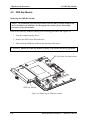
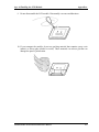
Procedure 1 ODD Cleaning Check
1. Turn off the power to the computer.
2. Open the ODD tray by inserting a slender object such as a straightened paper clip into the
eject hole. The object must be long enough to activate the eject mechanism.
3. Clean the laser pickup lens with a lens cleaner. Apply the cleaner to a cloth and wipe the
lens.
4. If the ODD drive still does not function properly after cleaning, go to Procedure 2.
Procedure 2 Test Program Check
Execute the ODD drive test program available as part of the maintenance test program. Insert the
diagnostics CD in the computer's CD, turn on the computer and run the test. Then insert a test
ODD (Toshiba-EMI DVD-ROM TEST DISK TSD-1) into the ODD drive. See Chapter 3 for
information on how to perform the test.
If any error is detected by the test, go to Procedure 3.
Procedure 3 Connector Check and Replacement Check
The ODD drive is connected to the system board by the connector. The connector may be
disconnected from the system board or faulty. Disassemble the computer following the steps
described in Chapter 4 and perform the following checks:
Check 1
Make sure the following connector has been firmly connected to the ODD
drive and the system board.
ODD
drive
Attachment case
System board
CPU
Connector
If the connector is loose or off, reconnect it firmly and return to Procedure 2.
If there is still an error, perform Check 2.
Check 2
The connector may be faulty. Replace the connector with a new one following
the steps in Chapter 4. If the ODD drive is still not functioning properly,
perform Check 3.
2-17
Satellite/Satellite Pro/L630/L635
Maintenance Manual
2 Troubleshooting
Check 3
Check 4
Check 5
2.8 ODD (Optical Disk Drive)
The ODD drive may be faulty. Replace the ODD drive with a new one
following the steps in Chapter 4. If the ODD drive is still not functioning
properly, perform Check 4.
The system board may be faulty. Replace it with new one following the
instructions in Chapter 4. If the ODD drive is still not functioning properly,
perform Check 5.
The memory may be defective. Replace the memory module with a new one
following the steps described in Chapter 4.
Satellite/Satellite Pro/L630/L635
Maintenance Manual
2-18
2.9 LAN
2 Troubleshooting
2.9 LAN
To check if the computer’s LAN is defective or malfunctioning, follow the troubleshooting
procedures below as instructed.
Procedure 1 Test Program Check
Procedure 2 Connector Check and Replacement Check
Procedure 1 Test Program Check
Execute the LAN check program available as part of the maintenance test program. This
program will check the LAN. Insert the Bootable CD into the CD. Turn on the computer and
run the check program. See Chapter 3 for information on how to perform the check.
If any abnormal is detected by the check, go to Procedure 2
Procedure 2 Connector Check and Replacement Check
The LAN connector (RJ45) is mounted on the system board. If the LAN malfunctions, the
system board or CPU might be faulty.
Disassemble the computer following the steps described in Chapter 4 and perform the following
checks:
Check 1
The system board may be faulty. Replace it with a new one following the
instructions in Chapter 4. If the LAN is still not functioning properly,
perform Check 2.
Check 2
The memory may be defective. Replace the memory module with a new one
following the steps described in Chapter 4. If the problem persists, perform
Check 3.
Check 3
The CPU may be faulty. Disassemble the computer following the steps
described in Chapter 4 and replace the CPU with a new one.
2-19
Satellite/Satellite Pro/L630/L635
Maintenance Manual
2 Troubleshooting
2.10Audio Test
2.10 Audio Test
To check if the computer’s Speaker is defective or malfunctioning, follow the troubleshooting
procedures below as instructed.
Procedure 1 Test Program Check
Procedure 2 Connector Check and Replacement Check
Procedure 1 Test Program Check
Execute the Audio test available as part of the maintenance test program. See Chapter 3 for
information on how to perform the test.
If an error is detected in the test, go to Procedure 2. If no error is detected, the Audio itself is
normal.
Procedure 2 Connector Check and Replacement Check
The Audio or system board may be disconnected or faulty. Disassemble the computer following
the steps described in Chapter 4 and perform the following checks:
Check 1
Make sure the Speaker cable has been firmly connected to the system board.
Speaker
System board
CPU
If the cable is loose or off, reconnect it firmly and return to Procedure 1. If
there is still an error, perform Check 2.
Check 2
The Speaker may be faulty. Replace it with a new one following the
instructions in Chapter 4. If the problem persists, perform Check 3.
Check 3
The System board may be faulty. Replace it with a new one following the
instructions in Chapter 4. If the Audio is still not functioning properly,
perform Check 4.
The memory may be defective. Replace the memory module with a new one
following the steps described in Chapter 4. If the problem persist, perform
Check 5.
Check 4
Check 5
The CPU may be faulty. Disassemble the computer following the steps
described in Chapter 4 and replace the CPU with a new one.
Satellite/Satellite Pro/L630/L635
Maintenance Manual
2-20
2.11 Cooling Module
2 Troubleshooting
2.11 Cooling Module
To check if the computer’s cooling module is defective or malfunctioning, follow the
troubleshooting procedures below as instructed.
Procedure 1 Test Program Check
Procedure 2 Connector Check and Replacement Check
Procedure 1 Test Program Check
Execute the Fan On/off test program available as part of the maintenance test program. This test
program checks the cooling module. Insert the diagnostics bootable CD in the computer's CD,
turn on the computer and run the test. See Chapter 3 for information on how to perform the test.
If any error is detected by the test, go to Procedure 2.
Procedure 2 Connector Check and Replacement Check
The cooling module is connected to the system board. If the cooling module malfunctions, there
may be a bad connection between the cooling module and the system board or either might be
faulty.
Disassemble the computer following the steps described in Chapter 4 and perform the following
checks:
Check 1
Make sure the cooling module has been firmly connected to the connector on
the system board. Also make sure that the tape is not stuck to any part of the
fan and that the fan is free of foreign matter.
Cooling module
Check 2
Check 3
Check 4
2-21
System board
CPU
If the connector is disconnected, connect it firmly to the system board and return
to Procedure 1. If the tape is stuck to any part of the fan, stick it back to the
specified point. If a foreign matter is found in the fan, remove it and then return
to Procedure 1. If there is still an error, perform Check 2.
The cooling module may be faulty. Replace it with a new one following the
steps in Chapter 4. If the cooling module is still not functioning properly,
perform Check 3.
The memory may be defective. Replace the memory module with a new one
following the steps described in Chapter 4. If the problem persists, perform
Check 4.
The CPU may be faulty. Disassemble the computer following the steps
described in Chapter 4 and replace the CPU with a new one.
Satellite/Satellite Pro/L630/L635
Maintenance Manual
Chapter 3
Diagnostic Programs
3 Diagnostic Programs
Chapter 3 Contents
3.1
General .......................................................................................................................... 1
3.2
Quick Start .................................................................................................................... 3
3.3
3.2.1
Quick Test ............................................................................................... 3
3.2.2
Customization Test .................................................................................. 3
3.2.3
Keyboard Layout test .............................................................................. 7
3.2.4
Audio Play Test ....................................................................................... 8
3.2.5
Audio Record Test................................................................................... 8
3.2.6
DMI Read ................................................................................................ 9
3.2.7
DMI Write ............................................................................................... 9
3.2.8
System Information ............................................................................... 11
3.2.9
View Logs ............................................................................................. 12
3.2.10
Exit to Free DOS .................................................................................. 13
3.2.11
The Diagnostics Screen Explanation..................................................... 13
Options ........................................................................................................................ 16
3.3.1
Overview ............................................................................................... 16
3.3.2
Batch Parameters Configuration ........................................................... 17
3.3.3
Item’s Parameters Configuration........................................................... 19
3.3.4
Load Batch Parameters.......................................................................... 20
3.3.5
Save Batch Parameters .......................................................................... 21
3.3.6
LOG Parameters Setting........................................................................ 21
3.3.7
Specify LOG Viewer ............................................................................. 23
3.3.8
Display LOG File .................................................................................. 23
3.3.9
LOG Viewer .......................................................................................... 24
3.3.10
LOG File Sample................................................................................... 25
3.4
Subtests ....................................................................................................................... 27
3.5
System Test ................................................................................................................. 30
3.6
Memory Test ............................................................................................................... 35
3.7
Storage ........................................................................................................................ 40
3.8
Video ........................................................................................................................... 44
ii Satellite/Satellite Pro L630/L635 Maintenance Manual
3 Diagnostic Programs
3.9
Communication (COMM) .......................................................................................... 52
3.10
Peripheral .................................................................................................................... 53
3.11
Error Codes and description........................................................................................ 57
3.12
Quick Test Item List ...................................................................................................... i
Satellite/Satellite Pro L630/L635 Maintenance Manual iii
3.1 General
3.1
3 Diagnostic Programs
General
This chapter explains the diagnostic programs which tests and diagnoses the functions of the
hardware components of this computer. The diagnostic programs can be classified into two
types: OPTION and DIAGNOSTIC TEST.
NOTE 1: This Diagnostic supports Bremen 10&10G
NOTE 2: Before test must set SATA Controller Mode to “Compatibility” in BIOS
Advanced setting, when finished test set it to “AHCI”
NOTE 3: Before running a test, be sure to:
1. Check that all the cables are connected securely.
2. Exit the application that is currently running and close Windows.
The OPTION includes the following functions:
Select All Items
Test Select Items
Edit Batch Parameters
Load Batch Parameters
Save Batch Parameters
Log Parameters
Specify Log Viewer
Display Error Log File
DOS Shell
Exit to Free-DOS
The DIAGNOSTIC TEST Devices include the following tests:
System Test
Memory Test
Storage Test
Video Test
Communication Test
Peripheral Test
Keyboard Layout Test
Hot Key Test
Audio Play Test
Audio Record Test
DMI Read
DMI Write
System Information
Satellite/Satellite Pro L630/L635 Maintenance Manual 1
3 Diagnostic Programs
3.1 General
Before running the diagnostic programs, get the following tools prepared:
A Service Diagnostic BOOT CD or USB Flash Memory
A Formatted FLOPPY DISK
A Test Media CD (A-BEX TEST CD-ROM TCDR-702)(for CD-ROM test)
A Test Media DVD (Toshiba-EMI DVD-ROM TEST DISK TSD-1)
An External Monitor (for DISPLAY test)
A CD-ROM Driver (for CD-ROM test)
Audio Line for audio record test
A Data CD (for CD-ROM test)
The following chapters describe all the test details. The test items could be selected from the
DIAGNOSTIC TEST menu.
Note:
When booting up the unit for the first time, the system will automatically select the location
of the result log file. If a USB floppy drive is connected, and there is an unprotected floppy
diskette with more then 50KB spare space in the drive, system will save all log files into the
root directory the diskette; otherwise, system will save all log files in the root directory of
RAM disk.
2 Satellite/Satellite Pro L630/L635 Maintenance Manual
3.2 Quick Start
3.2
3 Diagnostic Programs
Quick Start
When the system is booting from Service Diagnostic CD or USB Flash Memory, the following
screen will be displayed:
Please select a test item or select 0 to exit to Free-DOS:
3.2.1 Quick Test
When this item is selected, the system will run the configured test items and generate a test
report automatically.
When the test is completed, a file named Quick.log would be saved in the defined location.
When Quick.log is being created, meanwhile, a file named quick.log has already existed, the
system will automatically rename Quick.log to Quick.old for the backup purpose of the log file.
For the detail of test item, please refer to Quick Test Item List.
3.2.2 Customization Test
When this item is selected, the system will run the diagnostic programs according to the
procedures you defined. When the test is completed, a file named Custom.log will be saved in
the defined location. Please see the following example-- Mouse test.
Satellite/Satellite Pro L630/L635 Maintenance Manual 3
3 Diagnostic Programs
1.
3.2 Quick Start
Use arrow key to select ‘TouchPad’ item on ‘Peripheral’ in the menu, then press Space
key to select it. (When it is being selected, there is a X marked in the [ ])
Select ‘Test Mouse’ or press F8 to run the test. The prompt information would be
displayed in the screen as below. This test item needs user to verify whether the mouse
works normally.
The test result will be displayed in the following screen:
4 Satellite/Satellite Pro L630/L635 Maintenance Manual
3.2 Quick Start
3 Diagnostic Programs
Here is another method to run the test: Highlight a test item by using arrow keys, then,
press Enter to start. If there are parameters provided, user should set parameters in the
parameter dialog window.
CPU Speed Test (Step by Step):
1. Select test item:
Select System—CPU—CPU Speed, then, press the Enter key.
2. Parameters Setting
Choose the OK button after you set the proper parameters in the following window.
Satellite/Satellite Pro L630/L635 Maintenance Manual 5
3 Diagnostic Programs
3.2 Quick Start
3. Test Result
System will automatically run and display the test result as follows:
Following is the comparison report of the two testing methods mentioned above:
1) Configuration and Running
As to the method used in Mouse test, the user is required to select test items by pressing
Space key and set the parameters artificially, (See 3.3.3 Item’s Parameters
Configuration) Then press F8 to start the test. User should configure each parameter in
advance; otherwise the default parameters would be used. Using this method, user is
allowed to select more than one test item at one time.
2) Running the current test item
6 Satellite/Satellite Pro L630/L635 Maintenance Manual
3.2 Quick Start
3 Diagnostic Programs
As to the method adopted in CPU Speed test, user should highlight the test item and
press Enter to start testing. And the user has to setup the parameters every time before
running the test. Using this method, only one test item would be tested at one time.
3.2.3 Keyboard Layout test
The test purpose is to check whether 30 kinds of keyboards run well during the test
procedure. When users choose the item, the names of these countries will be displayed on
the screen for user choice. User press any index of token in ASCII, and the program will
test the kind of keymap of the country.
The test screen would be shown as below:
Satellite/Satellite Pro L630/L635 Maintenance Manual 7
3 Diagnostic Programs
3.2 Quick Start
It requires user to press the key and check whether the key in the screen changes
color or not. User can terminate test by typing ‘END’. When testing the ‘Fn’ key, it
must press the ‘ESC’ key at the same time.
When the user has checked all the keys and all the keys in the screen have changed
color, the diagnostics program would automatically end the test and report the pass
information.
If keyboard test fails, program will terminate the test and report the fail information
when it is time to timeout.
The test will end when all keys are pressed or test time is out after 90 seconds.
3.2.4 Audio Play Test
Check whether the system could playback audio normally. When the test is completed, a
file named Audio_p.log will be saved in the defined location.
3.2.5 Audio Record Test
Check whether the system could record the sound normally. If there is no error during
the whole test, Pass; otherwise, Fail. When the test is completed, a file named
Audio_r.log will be saved in the defined location.
8 Satellite/Satellite Pro L630/L635 Maintenance Manual
3.2 Quick Start
3 Diagnostic Programs
NOTE 1: This test only for internal microphone!
If the machine doesn't have camera module, then it doesn't have internal
microphone. This test result will fail due to no internal microphone.
3.2.6 DMI Read
Read the information from the system’s SMBIOS and display it in the screen as follows:
User can press any key to exit the program.
3.2.7 DMI Write
In addition to reading the DMI information, DMI Write also permits attributes editing
and updating: Manufacture, Product Name, Version, Serial Number, and OEM Part
Number, etc. The following screen will be displayed:
Satellite/Satellite Pro L630/L635 Maintenance Manual 9
3 Diagnostic Programs
3.2 Quick Start
In this screen, there are two lines which attribute could be edited and updated. The 1st
line (the font in yellow with blue background) shows the attribute’s value that is read
from the current system and the 2nd line (the font in red with turquoise background)
shows the same value as that in the 1st line before user’s editing. User can modify the
attribute’s value in the 2nd line and press Enter to confirm the current edition and
continue editing the next attribute.
During the editing, user could press F2 to confirm the DMI attribute update or press F4
to ignore the modification. Press ESC to exit the program of DMI Write.
The confirmation screen is as below:
10 Satellite/Satellite Pro L630/L635 Maintenance Manual
3.2 Quick Start
3 Diagnostic Programs
The attributes that have been modified would be marked in red; otherwise in yellow.
User could press F2 to save the changes, or press F4 to ignore and exit the current
program.
3.2.8 System Information
This function is used to read the system information. When the test is completed, a file
named System.log will be saved in the defined location. During the reading process, the
following screen will be displayed to indicate that the progress is in detection:
On the left column of the above screen, the detected hardware components are listed. The
corresponding information of the detected hardware components is displayed on the right
of the screen. It displays the current running status information of the check program.
The name of the program is marked on the top of the screen. At the bottom, the function
keys are listed for user operation. During the detection, keyboard operation is invalid.
When the detection is finished, the hardware components information will be displayed
as follows:
Satellite/Satellite Pro L630/L635 Maintenance Manual 11
3 Diagnostic Programs
3.2 Quick Start
User can use function keys listed on the bottom of the screen to display the configuration
of the component or exit the current program. On the left column, the components
information is listed and user can use arrow keys or PgUp/PgDn to view the list and
highlight the chosen component. On the right column, the configuration information of
the highlighted component is listed. Press ESC to exit this program.
3.2.9 View Logs
User can enter one choice to view a log file in the screen as follows.
12 Satellite/Satellite Pro L630/L635 Maintenance Manual
3.2 Quick Start
3 Diagnostic Programs
3.2.10 Exit to Free DOS
Select this item to exit to Free DOS.
3.2.11 The Diagnostics Screen Explanation
Below is an example of running a test item. It includes the following parts: Diagnostics
Windows, Test Status Area, Progress Bar, Error List, Test Item’s Title, Status Bar and
Message Box.
1. Diagnostics Windows
When a test item is running, a Diagnostics Windows is displayed in full screen. It consists of
the following parts: Title Bar, Test Running Status and Report Panel, Status Bar. There
would prompt a message box called USER BREAK in the central of the window whether
user press ESC to interrupt the test.
2. Test Running Status and Report Panel
Test Running Status and Report Panel are located on the middle of Diagnostics Windows.
Test item name, test process and test result are displayed in the left;
Test status and result are displayed in the upper right corner of the screen. It displays the
test status of the current test item – TEST (in testing), PASS (test finished and its result
is passed), FAIL (test finished and its result is failed) and SKIP (test skipped).
Satellite/Satellite Pro L630/L635 Maintenance Manual 13
3 Diagnostic Programs
3.2 Quick Start
The error list of each test module is displayed at the lower right corner of the screen. It
would display the total error quantity found in the test, the most recent five error codes
and description would be shown here. Detailed error report could be viewed with
Logview.exe.
When pressing ESC key during the test process, a User Break Windows will be popped
up for the user to select.
3. USER BREAK
Pressing ESC key to interrupt the test, USER BREAK message box would be prompted out
in the central of Diagnostics Window for the user to select the following actions:
CONTINUE---- Continue the test;
SKIP---- Stop the sub-item of current test item to go to the next item’s test;
ABORT----Stop the current test item to test the next module.
ABORT ALL---- Stop all the selected test items. User could use the hot key Ctrl+D to
achieve the same operation. When the user calls ABORT ALL, the following message
box will prompt for his selecting.
4. Title Bar:
Title Bar located at the top of the window, it includes information as follows:
Program Name and Its Version: Service Diagnostic Ver1.10;
Test Module Name: Label the name and version of the test module. For example, in the
above screen, the name of the test module is ‘Memory Tester Build Date 2007.02.09’.
Status Bar: Located at the bottom of the screen as follows:
The status bar is used to indicate the current script setting and test status. It consists of two
lines that includes the information as follows:
Test Mode: TIMEBOUND or LOOPBOUND, e.g. LOOPBOUND in the above screen;
14 Satellite/Satellite Pro L630/L635 Maintenance Manual
3.2 Quick Start
3 Diagnostic Programs
Script File Name: Script file name, e.g. ‘Custom.INI’ in the above screen;
Current Time(C. TIME): Current system time, e.g. ‘C.TIME:2008-02-16 00:42:40’ in
the above screen;
Test Time Remaining (LEFT): In TIMEBOUND mode, it would display the remaining
test time at the same location as Current TIME (C. TIME) in the above screen;
Current Loop Count: In LOOPBOUND mode, it will display the total LOOP number
planning to execute and the current LOOP number have been finished, e.g. ‘COUNT:
01/01’ in the above screen;
CPU Temperature: Detect the temperature in the current CPU, e.g. ‘CPU: 56C’ in the
above screen;
Remaining Battery Capacity: Remaining Battery Capacity detected in the current
Battery, e.g. ‘BAT: 46%’;
Test Order: Define the test sequence. There is two sequence modes: Sequential Test
Mode and Random Test Mode. The default mode is Sequential Test Mode, it would
displays ‘ORDER: SEQ’ as in the above screen;
LOG File Name: Display the file name of the test log, e.g. Custom.Log in the above
screen;
Start Test Time (S.TIME): Display the test start time for the current test item or the test
script, e.g. ‘S.TIME: 2008-02-16 00:42:28’ in the above screen;
Break On Error: Display ‘HALT’ as shown in the above screen when ‘Break On Error’
is enabled;
Wait On Error: Display ‘WAIT’ as shown in the above screen when ‘Wait On Error’ is
enabled;
Pause Enable: Display ‘PAUSE’ when “Pause Enable” is enabled;
Manual Interrupt Method: Display ‘Esc: Break’ to tell the user how to manually
interrupt the test process.
Satellite/Satellite Pro L630/L635 Maintenance Manual 15
3 Diagnostic Programs
3.3
3.3Option
Options
3.3.1 Overview
In Service Diagnostics, with the Options menu user can configure the batch
parameters, test item’s parameters and those parameters created by the LOG file.
Options Menu Notes:
• Select All/None Items
Switch between selecting all test items and selecting none. The hot key is F6.
• Test Selected Items
Execute all selected test items in this editor. The hot key is F8.
If “Interactive” option in batch parameters has not been selected, a warning
message would be shown as below:
16 Satellite/Satellite Pro L630/L635 Maintenance Manual
3.3 Option
3 Diagnostic Programs
• Edit Batch Parameters
Configure batch parameters and all the test item’s parameters.
• Load Batch Parameters
Upload all the test items and the parameters to the *.ini file.
• Save Batch Parameters
Save all the parameters and the test items that are configured in the editor to a
specified file.
• Log Parameters
Configure LOG parameters.
• Specify LOG Viewer
Specify the viewer for the LOG file.
• Display Error Log File
Load the LOG file viewer specified in the Specify Log Viewer to view the LOG
file.
• DOS Shell
Enter the DOS Shell and execute the DOS programs. You can also exit to the
Service Diagnostics Editor by the command of EXIT.
• Exit to DOS
Exit the Service Diagnostics Editor and back to DOS.
3.3.2 Batch Parameters Configuration
The batch parameters configuration screen can be accessed through Service
Diagnostics/OPTIONS -> EDIT BATCH PARAMETERS -> BATCH
PARAMETERS:
Satellite/Satellite Pro L630/L635 Maintenance Manual 17
3 Diagnostic Programs
•
3.3Option
Test Order
Specify the order of the test items. Choose 'Sequence' to adopt the sequential
mode; choose 'Random' to run the test items in random sequence.
•
Test Options
Choose one of the following options:
9
Wait On Error
Wait for further confirmation while an error occurs.
9
Break On Error
Stop the test when a test item fails.
9
Pause Enable
Pause at the end of each test items and wait for the user to response with the test
items that requires the user to assist the test processes, such as the keystroke test.
9
Interactive
If the item is enabled during the test, the test items that need user to response can
run normally, such as Mouse test; If it is disabled, those test items will report
FAIL.
When the option here is enabled, it would affect all the test items while the same
option in “Item Parameters Configuration” only affect that test item.
9
Monitor Battery Life
18 Satellite/Satellite Pro L630/L635 Maintenance Manual
3.3 Option
3 Diagnostic Programs
Monitor the remaining battery capacity (percent).
9
Monitor CPU Thermal
Monitor the CPU temperature.
•
9
Test Mode
LOOPBOUND
The chosen test items will run repeatedly according to the times specified in the
'Number of Loops'.
9
TIMEBOUND
The chosen test items will run for an extent time specified in 'Time Limit Hrs' and
'Time Limit Min'.
•
Time Limit Hrs
Specify the hours whether 'TIMEBOUND' is chosen under the batch mode.
•
Time Limit Min
Specify the minutes whether 'TIMEBOUND' is chosen under the batch mode.
•
Number Of Loops
Specify the repeating times when 'Loop Bound' is chosen under the batch mode.
3.3.3 Item’s Parameters Configuration
The test items’ parameters configuration screen can be accessed through Service
Diagnostics/Options -> Edit Batch Parameters -> Item’s Parameters-> System>CPU-> Basic Functionality:
•
Repeat count
Satellite/Satellite Pro L630/L635 Maintenance Manual 19
3 Diagnostic Programs
3.3Option
Repeat times of the test item.
•
Interactive
If the item is enabled during the test, the test items that need user to response can
run normally, such as PS2 Mouse test; If it is disabled, those test items will
report FAIL.
Whether the option here is enabled, it only affects the current test item.
•
Parameters
For the test items with specific parameters, this option will call the related
configuration screens. Otherwise, the program will show the following dialogue
window:
Parameters for the specific test items:
Some test items (Memory, HDD, e g...) have their individual parameters, which
can be configured in their parameters setting window.
3.3.4 Load Batch Parameters
Batch parameter is saved in the script file whose extension name is INI (*.INI).
Below is the screen shot of “Load Batch Parameters”.
20 Satellite/Satellite Pro L630/L635 Maintenance Manual
3.3 Option
3 Diagnostic Programs
In this window, you can specify the .INI files that you wanted to be edited or
modified.
3.3.5 Save Batch Parameters
Here you can save the edited or modified content to the batch parameters files.
3.3.6 LOG Parameters Setting
You can access the Log Parameters screen through Service Diagnostics\Options Generate Report.
Satellite/Satellite Pro L630/L635 Maintenance Manual 21
3 Diagnostic Programs
•
3.3Option
Report Destination
If selecting 'NONE', no log file will be generated; if selecting 'FILE', a log file with
the name specified in 'Log File Name' will be generated.
•
Log Options
9
Log Errors
If selecting this parameter, errors will be recorded when the test fails.
9
Log Test Activities
If selecting this parameter, the subtest results will be recorded.
9
Log Test Start Time
If selecting this parameter, the start time of the test will be recorded.
9
Log Test End Time
If selecting this parameter, the end time of the test will be recorded.
9
Log Errors Only
If selecting this parameter, errors will be recorded only when the test fails.
9
Log Errors Only with Time
If selecting this parameter, errors and time will be recorded only when the test
fails.
9
Append to Old Log File
If selecting this parameter, the new log will be added to the old one.
22 Satellite/Satellite Pro L630/L635 Maintenance Manual
3.3 Option
9
3 Diagnostic Programs
Log Device Info on Fail
If selecting this parameter, details of the failed test will be recorded.
•
Log file Name
Specify the Log file name. You can input the detail path of the file. System will
show the detail path of the file.
3.3.7 Specify LOG Viewer
You can specify the Log file viewer in the Specify Log Viewer screen.
The default viewing program of Service Diagnostics is LogView.exe.
3.3.8
Display LOG File
You can specify the Log file for viewing in the Display Error Log File screen.
Satellite/Satellite Pro L630/L635 Maintenance Manual 23
3 Diagnostic Programs
3.3Option
In this screen, you can specify a Log file and view it with the viewer designated in
Specify LOG Viewer.
3.3.9 LOG Viewer
Service Diagnostic Log viewer:
•
↑, ↓
Scroll a line backward or forward on the screen.
•
Page Up, Page Down
Scroll a page backward or forward on the screen.
•
Esc
Exit the Log viewer.
•
F1
Display the Help information about the Log viewer operations and the
functional keys.
•
Ctrl+Home
Go to the start of the log file.
•
Ctrl+End
Go to the end of the log file.
•
Ctrl+F3
24 Satellite/Satellite Pro L630/L635 Maintenance Manual
3.3 Option
3 Diagnostic Programs
Prompt the search dialogue for the user to input the string to be looked for
and specify the searching method.
•
F3
Find the next corresponding strings given.
3.3.10 LOG File Sample
Log file is a test result file, which records the following information: Test module name,
Test item name, Start/End time and the test result (including PASS, FAIL, SKIP and
ABORT). When a failure is found, both the error code and the error information were
recorded.
In the Log file, we use Test Items as the test item name, which could not be modified in
the whole time. And we use the Internal Name as name in the program’s UI, which
corresponds to the test item name and could be modified according to the user’s favorite.
The following section is a sample of log file:
DIAG REPORT
<Module Name>: Service Diagnostic Ver 1.00 ... Memory Tester Build Date 2006.01.10
[Walk High]
Begin Time: Wed Jul 05 10:45:36 2006
Base Memory Test
: PASS
Extended Memory Test
: PASS
End Time: Wed Jul 05 10:47:51 2006
<Module Name>: Service Diagnostic Ver 1.00 ... Mouse Test Build Date 2006.01.10
[MSTPad]
Begin Time: Wed Jul 05 10:48:54 2006
Touch Pad Test
: FAIL
Satellite/Satellite Pro L630/L635 Maintenance Manual 25
3 Diagnostic Programs
ITEM TEST FAIL
Function ID :502
Error Code
:50202
Error Message :Touch Pad Test Fail
End Time: Wed Jul 05 10:49:16 2006
26 Satellite/Satellite Pro L630/L635 Maintenance Manual
3.3Option
3.4 Subtests
3.4
3 Diagnostic Programs
Subtests
Test
Group
System
Sub
Item
Subtest
ID
01 CPU
02
Memory
Board
03
FAN
01
BIOS ROM
02
Pattern
03
Extended Pattern
Test
ID
Test items
Internal Name
01 Basic Functionality Test
[CPUBasicFun]
02 CPU Speed
Coprocessor
03
NPU Basic Functions
04 CPU Information
[CPUSpeed]
Coprocessor
[NPUFun]
[CPUInformation]
05 CPU Protected Mode
[Protect]
06 MMX
[MMX]
01 DMA Controller
[DMACtrl]
02 Interval Timer
[Timer]
03 Clock / Calendar
[RealClock]
04 PCI System
[PCI]
05 Plug and Play
[PnP]
06 ACPI Test
[ACPI]
01 CPU Fan Speed Test
[FANSpeed]
[BIOSROM]
01 Bit Stuck High Test
[BSHigh]
02 Bit Stuck Low Test
[BSLow]
03 Checker Board Test
[ChkBd]
04 CAS Line Test
[CASLine]
05 Incremental Test
[Incrment]
06 Decremental Test
[Decrment]
07 Incremental Decremental Test
[Idcrment]
01 Write/Read Cycle Test
[XWRCycle]
02 Read Cycle Test
[XRCycle]
04
Walking 1's Test
[WalkHigh]
05
Walking 0's Test
[WalkLow]
06
Memory Address
[Address]
07
Refresh Test
[Refresh]
08
Cache Memory
[CacheOne]
09
Random Memory
01 Randomize Test
[Random]
02 Random Increment Read/Write
[RandIncr]
Satellite/Satellite Pro L630/L635 Maintenance Manual 27
3 Diagnostic Programs
10
Data Bus Test
[DataBus]
11
Bus Noise
[BusNoise]
12
Storage
01
02
Video
3.4 Subtests
01
02
03
Memory Speed
Test
HDD
ODD
Text Mode
[MemSpeed]
01 Sequential/Random R/W
[SeqRdRW1]
02 Sequential/Random Seek
[Seek1]
03 Performance
[Perform1]
04 Controller Check
[Controller1]
05 Diagnostic Read/Write
[DiagRW1]
06 SMART Test
[SMART1]
01 Controller Test
[CDRWController]
02 Data Transfer Rate
[CDRWTransRate]
03 Data CD Butterfly Seek
[CDRWButterfly]
04 Data CD Random Seek
[CDRWSeek]
05 Data CD Sequence Seek
[CDRWSFSeek]
06 Tray Eject Test
[CDRWTray]
01 Character Test
[CharTest]
02 Text Attribute
[Attribut]
03 Text Page Selection
[PageSel]
04 Text Color
[Color]
05 80*25 Text Mode
[Text Mode]
640*480 VGA
Mode
VESA Video
Modes
[VGAMode]
640X480 Video Modes
VESA 640x480x256 Mode
VESA 640x480x32K Mode
01
VESA 640x480x64K Mode
VESA 640x480x16K Mode
VESA 640x480x32bit Mode
800X600 Video Modes
VESA 800x600x256 Mode
VESA 800x600x64K Mode
02 VESA 800x600x32K Mode
VESA 800x600x16K Mode
VESA 800x600x32bit Mode
1024X768 Video Modes
03 VESA 1024x768x256 Mode
VESA 1024x768x64K Mode
28 Satellite/Satellite Pro L630/L635 Maintenance Manual
[V640480_15]
[V640480_16]
[V640480_24]
[V640480_32]
[V800600_15]
[V800600_16]
[V800600_24]
[V800600_32]
[V1024768_15]
[V1024768_16]
[V1024768_24]
3.4 Subtests
3 Diagnostic Programs
VESA 1024x768x32K Mode
[V1024768_32]
VESA 1024x768x16K Mode
VESA 1024x768x32bit Mode
05
VESA Video
Memory
AGP Test
[AGP]
06
LCD Panel Test
[LCDPanel]
07
Register Test
[Register]
08
Color Purity Test
[ColPurity]
09
Direct Color Test
DAC/Palette
Address
Bitblt Engine
Test
LAN Card
[DirectColor]
04
10
11
COMM
Peripheral
01
01
Keyboard
[VESAMEM]
[DACPalAddr]
[Bitblt]
01 Device ID Detection
[DeviceID]
02 Vendor ID Detection
[VendorID]
03 Mac Address Detection
[MAC Address]
01 Keyboard Data Line
[KBDataLn]
02 Keyboard Clock Line
[KBClokLn]
02
Mouse
01 TouchPad
[MSTpad]
03
Led
01 Device Led
[KBLED]
Satellite/Satellite Pro L630/L635 Maintenance Manual 29
3 Diagnostic Programs
3.5
3.5 System Test
System Test
Move arrow keys and press the Space key to select CPU test item from Service
Diagnostic menu, then highlight CPU and press the Enter to run this test item.
Subtest 01 CPU
1. Basic Functionality Test
This test item is to check whether the CPU works normally through math and
logic calculation, which means verifying the general registers, math registers
and logic registers.
2. CPU Speed
This test item is to detect the work frequency of the current CPU. User should
change the parameters setting in the following window before the test:
30 Satellite/Satellite Pro L630/L635 Maintenance Manual
3.5 System Test
3 Diagnostic Programs
CPU Speed Comparison--Whether you want to make a comparison of the
CPU speed with the value set in ‘Expected CPU Speed’, you should choose
‘Yes’; otherwise, ‘No’.
Expected CPU Speed--Specify the expected CPU Speed value you want
for further comparison.
Allowable Error Rate-- Specify the Allowable Error Rate value you want
for further comparison.
3. Coprocessor
9
NPU Basic Functions Test
This test item is to check whether the precision of the numeric processor in
the float calculation is up to the IEEE standards.
4. CPU Information
This test item is used for getting & showing CPU Information. It will be
displayed as follows:
Satellite/Satellite Pro L630/L635 Maintenance Manual 31
3 Diagnostic Programs
3.5 System Test
5. CPU Protected Mode Test
This test item is to check whether CPU protected mode instruction works
normally.
6. MMX
The test item is to confirm whether the CPU supports MMX instructions.
Subtest 02 Boards
1. DMA Controller
This test item is to check whether the DMA controller works normally.
2. Interval Timer
This test item is to check whether the Interval Timer (18.2Hz, 55ms) works
normally.
3. Clock/Calendar
This test item is to check whether the system clock/calendar works
normally.
4. PCI System
This test item is to check whether the bus number, device number and
function number in PCI bus are valid.
32 Satellite/Satellite Pro L630/L635 Maintenance Manual
3.5 System Test
3 Diagnostic Programs
5. Plug and Play
This test item is to check:
1. Whether the current system supports Plug-n-Play;
2. Whether there is an ESCD (Extended System Configuration Data) in
the BIOS;
3. Whether there is PCI-to-ISA bridge in the system;
4. Whether there is PCI bus in the system.
6. ACPI Test
ACPI test includes two sub-items as below:
System Address Map Test: Check the correctness of ACPI system memory
map, and whether its mapping scope is within real memory.
ACPI Table Test: Check the correctness of ACPI relative configuration
tables in the current system.
Subtest 03 FAN Speed Test
1. CPU Fan Speed Test
This test item is to check whether the CPU fan currently used works
normally in the different speeds of stop, slow, middle and fast.
It will be displayed as follows:
Satellite/Satellite Pro L630/L635 Maintenance Manual 33
3 Diagnostic Programs
34 Satellite/Satellite Pro L630/L635 Maintenance Manual
3.5 System Test
3.6 Memory Test
3.6
3 Diagnostic Programs
Memory Test
This test module is to check whether the memory chip works normally.
Subtest 01 BIOS ROM
This test item is to check the validity of BIOS ROM that includes two sub-items -ROM Read and ROM Write Protection. ROM Read is to check whether BIOS
ROM could be correctly read out, ROM Write Protect is to check whether BIOS
ROM is write-protected.
Subtest 02 Patterns
This test item is to check whether the system memory includes base memory and
extended memory that could be accessed correctly through writing and reading
with a series of designed pattern data. Below is the parameter setting dialog
window.
Test Option: Choose the Memory part to take the test– Base Memory or
Extended Memory.
Extended Memory Test Range: Specify the test coverage range of
Extended Memory. If user chooses Total Size, it means that the whole
Extended Memory will be tested. Although user can input the parameter
into other select box, but the selected result is invalid. If user chooses
Special Size, the test of Extended Memory will be taken according to the
coverage range that user chooses or time.
Satellite/Satellite Pro L630/L635 Maintenance Manual 35
3 Diagnostic Programs
3.6 Memory Test
Extended Memory Start Address (MB) & Extended Memory End
Address (MB): Set the range of extended memory that is to be tested, the
test coverage would be based on the setting and the value in ‘Percent (%)
mentioned at below.
Pattern Size: Choose the pattern size – BYTE, WORD, DWORD or ALL.
Percent (%): Choose the percentage of the defined range of the memory to
be tested.
Time Limit(h): Choose or Input the time (hour) of the defined range of the
memory to be tested.
Time Limit(m): Choose or Input the time (minute) of the defined range of
the memory to be tested.
1. Bit Stuck High Test
Data pattern: Every bit is ‘1’ (Each bit is high)
2. Bit Stuck Low Test
Data pattern: Every bit is ‘0'(Each bit is low);
3. Checker Board Test
Data pattern: Lo-byte and hi-byte are composed with 0101(0x5) and 1010
(0xA);
4. CAS Line Test
Data pattern: Lo-byte and hi-byte are composed with 0000 (0x0) and
1111(0xF);
5. Incremental Test
Data pattern: A series of increasing data from 0 by adding 1 each time;
6. Decrement Test
Data Pattern: A series of decreasing data from the maximum (e.g. 0xFFFF) by
subtracting 1 each time;
7. Incremental / Decrement Test
Data Pattern is a series of data whose low byte is increasing data from 0x00
and high byte is decreasing data from 0xFF.
36 Satellite/Satellite Pro L630/L635 Maintenance Manual
3.6 Memory Test
Subtest 03
3 Diagnostic Programs
Extended Pattern
In addition to the above pattern test of the memory, there is Read/Write Cycle test
and Read Cycle Test for the extended memory.
Below is the parameter dialog window of the extended pattern test.
Test Range: Specify the test coverage range of Extended Memory. If
user chooses Total Size, it means that the whole Extended Memory
will be tested. Although user can input the parameter into other select
box, but the selected result is invalid. If user chooses Special Size, the
test of Extended Memory will be taken according to the coverage
range that user chooses or time.
Extended Memory Start Address and Extended Memory End
Address (MB): Set the range of extended memory that is to be tested.
The test coverage will be according to the value setting in ‘Percent
(%)’ mentioned at below.
Percent (%): Choose the percentage of the defined range of the
memory to be tested.
Time Limit(h): Choose or Input the time (hour) of the defined range
of the memory to be tested;
Time Limit(m): Choose or Input the time (minute) of the defined
range of the memory to be tested.
1. Write/Read Cycle Test
Test by using both read and write instructions.
Satellite/Satellite Pro L630/L635 Maintenance Manual 37
3 Diagnostic Programs
3.6 Memory Test
2. Read Cycle Test
Test by using read instructions.
Subtest 04 Walking 1’s Test
The test item is to ensure that there is no short circuitry issue in memory chip. The
parameter dialog window is the same as that in ‘Subtest 02 Pattern’.
Subtest 05 Walking 0’s Test
The test item is to ensure that there is no open circuitry issue in memory chip. The
parameter dialog window is the same as that in ‘Subtest 02 Pattern’.
Subtest 06 Memory Address
This test item is to check short and open issue on memory address lines.
Subtest 07 Refresh Test
This test item is to check whether the memory refresh works normally. The
parameter dialog window is as follows:
Subtest 08 Cache Memory
The test item is to check whether the CPU internal cache memory could be
accessed correctly.
Subtest 09 Random Memory
Random Memory test includes the following two test items: Randomize Test and
Random Incremental Read/Write Test. The parameter dialog window is the same
as that in ‘Subtest 03 Extended Pattern’.
1. Randomize Test
This test item is to check whether the memory could be correctly accessed
with randomized data and randomized memory address.
38 Satellite/Satellite Pro L630/L635 Maintenance Manual
3.6 Memory Test
3 Diagnostic Programs
2. Random Increment Read/Write
This test item is to check whether the memory could be correctly accessed
with randomized memory address and a series of incremental data.
Subtest 10 Data Bus Test
This test item is to check whether the data bus works normally.
Subtest 11 Bus Noise Test
This test item is to check whether the bus noise works normally.
Subtest 12 Memory Speed Test
This test item is to check the data-transferring rate for the cache memory and the
system memory.
Satellite/Satellite Pro L630/L635 Maintenance Manual 39
3 Diagnostic Programs
3.7
3.7 Storage
Storage
Subtest 01 HDD
This test item runs on IDE hard disks. It checks the functions and performance of IDE
hard disk.
In order to protect user’s HDD data, the password must be verified before the
HDD test. The screen is as follows:
Password:hard disk
1. Sequential/Random R/W
This test item is to check the HDD’s Read/Write function through data writing
and reading to HDD.
This test item needs user to submit the parameters:
IDE HDD Test Range-- Specify the test coverage range of IDE HDD. If user
chooses Total Size, it means that the whole IDE HDD will be tested. Although
user can input the parameter into other select box, but the selected result is
40 Satellite/Satellite Pro L630/L635 Maintenance Manual
3.7 Storage
3 Diagnostic Programs
invalid. If user chooses Special Size, the test of IDE HDD will be taken
according to the coverage range that user chooses or time.
LBA Start, LBA End--Specify the start and end byte in LBA (Large Block
Address).
Percent—Specify the coverage rate in percentage of the total disk.
Time Limit(h): Choose or Input the time (hour) of the defined range of the total
disk to be tested.
Time Limit(m): Choose or Input the time (minute) of the defined range of the
total disk to be tested.
Test Mode—Choose test mode from the following options:
(1) Read & Write –Write data on the disk, then read it out and compare the two
value;
(2) Read Verify —Read data only;
(3) Unprotected Write—Write data on the disk without backup original data.
Option—Select sequential test or random test
2. Sequential/Random Seek
The test item is to check the correctness of the HDD’s sector’s seeking function.
This test item involves the following parameters:
Satellite/Satellite Pro L630/L635 Maintenance Manual 41
3 Diagnostic Programs
3.7 Storage
IDE HDD Test Range—is same as the description of the upper item.
LBA Start, LBA End-- specify start and finish byte in LBA(Large Block
Address);
Option-- Select sequential test or random test;
Percent-- Specify the coverage rate in percentage of the total disk.
Time Limit(h): Choose or Input the time (hour) of the defined range of the total
disk to be tested;
Time Limit(m): Choose or Input the time (minute) of the defined range of the
total disk to be tested.
3. Performance
Check the HDD’s seeking speed and transfer the data rate.
4. Controller Check
Check the HDD controller’s status, including HDD interrupt and unexpected
interrupt.
5. Diagnostic Read/Write
This test item is a quick test to verify whether the HDD could be correctly
accessed and the user could specify the percentage in the below dialog.
Percent (1-100)-- Specify the coverage rate in percentage of the total disk.
Time Limit(h): Choose or Input the time (hour) of the defined range of the total
disk to be tested;
Time Limit(m): Choose or Input the time (minute) of the defined range of the
total disk to be tested;
42 Satellite/Satellite Pro L630/L635 Maintenance Manual
3.7 Storage
3 Diagnostic Programs
6. SMART Test
SMART stands for Self-Monitoring, Analysis and Reporting Technology.
SMART test will compare the attribute values with the threshold value in the
HDD’s controller to confirm whether there is any failure in the HDD
Subtest 02 ODD
The ODD test runs on IDE CDROM/DVD-ROM & CD-RW. It will check the ODD
driver’s functionality and performance.
1. Controller Test
Check the CDROM controller’s status.
2. Data Transfer Rate
Check the data transfer rate of the ODD drive. It will read data from the ODD disc
and calculate the data transfer rate. This test needs a data CD.
3. Data CD Butterfly Seek
Check the seek function of the ODD drive. It will perform a serial of seeking
operations. First, locate the minimum LBA address, then the maximum, the subminimum, the sub-maximum and meet at center point. This test needs a data CD.
4. Data CD Random Seek
Check the random seek function of ODD drive. Random access will reflect the
performance of the heads’ random movement and seek. It tests for 1000 times.
5. Data CD Sequence Seek
Check the sequential seek function of ODD drive. Perform location test to CDRW under LBA mode with the location address increasing in sequence.
6. Tray Eject Test
Check the eject function of the ODD. It will eject the ODD and ask the user to
confirm if the operation succeeds.
Satellite/Satellite Pro L630/L635 Maintenance Manual 43
3 Diagnostic Programs
3.8
3.8 Video
Video
This test item tests the video by:
1.
2.
displaying the figures in different graphic modes.
displaying the property and color of the characters in different text modes.
User will confirm whether each video mode works normally by judging whether the display
is correct. It checks whether the video memory works normally by writing data into the video
memory, then reading it out and comparing the two value.
Subtest 01
Text Mode
1. Character Test
Tests two types of font patterns.
Font 9*14
Font 9*16
It requires the user to check whether all characters of each font type displayed
correctly by answering the questions prompted on screen. It will be displayed as
follows:.
2. Text Attribute
This test item is to check whether the text attribute of normal, hi-intensity,
inverse, and blinking in VGA text mode could be correctly displayed on the
screen.
44 Satellite/Satellite Pro L630/L635 Maintenance Manual
3.8 Video
3 Diagnostic Programs
It would display the below texts of the different attributes in the screen:
1.
2.
3.
4.
5.
6.
Text in normal attribute;
Text in blinking normal attribute;
Text in inverse attribute;
Text in blinking inverse attribute;
Text in hi-intensity attribute;
Text in blinking hi-intensity attribute;
Users need to check whether all texts displayed correctly in the above six
attributes and key in the answer ‘Y’ or ‘N’ to the prompts ‘Is this display OK?
[Y/N<Enter=Y>]’.
Below is the test screen of Text Attribute.
3. Text Page Selection
This test item is to check whether the video memory could be correctly written
and read in VGA text mode. According to the comparison of written data with
read data, the program would report PASS or FAIL.
Satellite/Satellite Pro L630/L635 Maintenance Manual 45
3 Diagnostic Programs
3.8 Video
4. Text Color
This test item is to check whether all 16 colors foreground and all 8 colors
background works normally in VGA text mode.
The bit4-6 of the attribute byte of a character defines 8 background colors (black,
blue, green, cyan, red, brown, magenta, and light gray), and the bit0-3 defines 16
foreground colors (dark gray, light blue, light green, light cyan, light red, light
magenta, yellow, and white besides the above 8 colors).
In the test, user is required to respond according to the instruction in the screen.
5. 80 * 25 Text Mode
46 Satellite/Satellite Pro L630/L635 Maintenance Manual
3.8 Video
3 Diagnostic Programs
This test item is to check whether 80*25 Text Mode works normally.
In the test, user is required to respond according to the instruction in the screen.
Subtest 02
640 * 480 VGA Mode
This test item is to check whether 680*480 VGA Text mode works normally.
In the test, user is required to respond according to the instruction in the screen.
Satellite/Satellite Pro L630/L635 Maintenance Manual 47
3 Diagnostic Programs
Subtest 03
3.8 Video
VESA Video Modes
This test item is to check whether all the video modes supported by the video card
works normally.
In the test, user is required to respond following the instruction in the screen.
1. 640X480 Video Modes Test
2. 800X600 Video Modes Test
3. 1024X768 Video Modes Test
Subtest 04
VESA Video Memory
This test item is to check whether VESA video memory could be correctly
accessed (write data & read data). Below is the test item’s parameter dialog
window:
48 Satellite/Satellite Pro L630/L635 Maintenance Manual
3.8 Video
3 Diagnostic Programs
If press Ctrl+Break to force the test to terminate during execution of VESA
Video Memory, the test program will not operate and display properly in further
tests.
Subtest 05
AGP Test
This test item is to report the system’s Accelerated Graphics Port status and check
whether AGP registers works normally.
Subtest 06
LCD Panel Test
This test item is to check whether there is any fault in its resolution by displaying
the RGB gradient color screens.
Satellite/Satellite Pro L630/L635 Maintenance Manual 49
3 Diagnostic Programs
Subtest 07
3.8 Video
Register Test
This test item is to check whether the registers of the video adapter works
normally.
Subtest 08
Color Purity Test
This test item is to check whether the system (the video adapter and the display)
could display the purity color of red, green, blue, black and white.
In the test, user is required to respond according to the instruction in the screen.
Subtest 09
Direct Color Test
This test item is to check the video adapter’s composing ability of direct color in
high and true color mode.
In the test, user is required to respond according to the instruction in the screen.
50 Satellite/Satellite Pro L630/L635 Maintenance Manual
3.8 Video
Subtest 10
3 Diagnostic Programs
DAC/Palette Address
This test item is to check the function of DAC registers and Palette registers.
In the test, user is required to respond according to the instruction in the screen.
Satellite/Satellite Pro L630/L635 Maintenance Manual 51
3 Diagnostic Programs
3.9
3.9 Communication (COMM)
Communication (COMM)
Subtest 01
LAN Card
This test item is to check whether the module can detect the existence of the network
card and display its related information.
1. Device ID Detection
Detect the device ID of the network card.
2. Vendor ID Detection
Detect the vendor ID of the network card.
3. MAC Address Detection
Detect the MAC address of the network card.
52 Satellite/Satellite Pro L630/L635 Maintenance Manual
3.10 Peripheral
3 Diagnostic Programs
3.10 Peripheral
Subtest 01
Keyboard
This test item is to check whether the keyboard works normally.
1. Keyboard Data Line Test
Check whether the keyboard data line works normally.
2. Keyboard Clock Line Test
Check whether the keyboard clock line works normally.
Subtest 02
Mouse Test
Check whether the point devices work normally.
1. Touch Pad
Before test Touch Pad’s function, user should set a timeout time at below screen:
At the below screen of Touch Pad test, user can press the left button, right button,
and move the mouse to verify its functions for times, and the test will end either
by user break or test time is out.
Satellite/Satellite Pro L630/L635 Maintenance Manual 53
3 Diagnostic Programs
Subtest 03
Led Test
1. Led Test
NOTE 1: This Test can not support 3 in 1 LED Test
Check whether the white led works normally.
54 Satellite/Satellite Pro L630/L635 Maintenance Manual
3.10 Peripheral
3.10 Peripheral
3 Diagnostic Programs
Check whether the orange led works normally.
Check whether the HDD led works normally.
Satellite/Satellite Pro L630/L635 Maintenance Manual 55
3 Diagnostic Programs
56 Satellite/Satellite Pro L630/L635 Maintenance Manual
3.10 Peripheral
3.11Error Codes and Description
3 Diagnostic Programs
3.11 Error Codes and description
The format of ‘Error Code’ is ‘ddxxee’, and ‘dd’ is the device ID (1~2 chars), ‘xx’ is test function
ID of device (2 chars), ‘ee’ is the error code of device (2 chars); the range of error code is from 01
to 99 in each device (the common error codes in all device are set to 99 and spanned).
Device
ddxx
Error
Description
Code
ee Common Error
94
01xx
Interactive Mode Needed
Cause
Action
The test is not under interactive
mode.
Check whether the interactive test
mode is adopted.
Replace the CPU.
CPU
01
CPU General Function
Error
The CPU General Function
register is damaged.
02
CPU Arithmetic Error
The CPU Arithmetic Register is
As above.
damaged.
03
CPU Logic Error
The CPU Logic Register is
damaged.
As above.
04
CPU Type Error
The CPU Type is not
supportable.
Check whether the CPU is Intel
CPU.
05
CPU Speed Error
The CPU speed differs from the Check the CPU speed and the set
expected value.
expected speed.
06
NPU General Function
Error
The NPU arithmetic unit is
damaged.
Replace the CPU.
07
NPU Interrupt Error
The NPU is damaged.
As above.
08
CPU Information Error
Information of the CPU cannot
be acquired.
Check whether the CPU is Intel
CPU.
09
Protected Instruction Error The CPU is damaged.
21
MMX Test Error
02xx
Replace the CPU.
The CPU MMX register is
damaged.
Replace the CPU.
Memory
01
Read Error
The ROM BIOS has Physical
problems.
Test this unit on multiple
machines.
02
Write-Protect Error
The ROM BIOS has Physical
problems.
As above.
03
Base Memory Error
Address
The test pattern read out from the
base memory is different from Test this memory chip on
the one that has been written in multiple machines.
this address.
Satellite/Satellite Pro L630/L635 Maintenance Manual 57
3 Diagnostic Programs
3.11Error Codes and Description
04
The test pattern read out from the
extension memory is different
As above.
(XMS)Memory Problem
from the one that has been
written in this address.
05
(XMS) Out Of Range
06
Address Test Error
07
Toggle Bit Error
08
Interval Error
Wrong parameters setup.
Check and reset the parameters.
Interference between different
address channels.
Errors with the timer chip.
The acquired refreshing
frequency is out of the estimated
range.
Test this memory chip on
multiple machines.
As above.
Reset the estimated range.
09
L1 Cache test Error
The pattern read out from the L1
Cache is different from the one Test this unit on multiple
that has been written in the same machines.
address.
12
Data Bus Error
Interference between different
data channels.
14
Speed Error
Failure during the transfer speed
As above.
test.
03xx
As above.
Board
Repeat multiple times. Whether
there is always the same error,
replace the board.
DMA Test Error
DMA channel cannot transfer
data normally.
04
Interval Timer Error
The difference between the
actual precision of the interval
timer and its theory value is out As above.
of the permitted range. The timer
counts imprecisely.
05
Periodic Faster Error
The frequency is beyond the
standard.
As above.
06
Periodic Slower Error
The frequency is below the
standard.
As above.
07
Update-ended Interrupt
Error
R/W errors with the RTC
refreshing interrupt controller.
As above.
08
RTC Alarm Error
The PC speaker's sound source --counter/timer 8253 cannot
As above.
produce corresponding timing
signal.
13
14
15
PCI Bus Error
No PCI.
PCI Bus Scan Error
PCI test fails.
PCI Device Access Error PCI access fails.
Check the board.
As above.
As above.
16
PCI Config Verification
Error
Check PCI configuration on main
board or PCI Device
01
Wrong PCI configuration.
58 Satellite/Satellite Pro L630/L635 Maintenance Manual
3.11Error Codes and Description
3 Diagnostic Programs
configuration.
17
PCI to ISA Bridge Error
PCI-ISA bridge errors.
18
53
ESCD Error
ACPI Table Test Error
FAN
Fan Slow Speed Test Fail
Fan Stop Test Fail
Fan Fast Speed Test Fail
Video
ESCD errors.
Errors with the ACPI table test.
Repeat multiple times. If there is
always the same error, replace the
board.
As above.
As above.
The fan slow speed test fails.
The fan stop test fails.
The fan fast speed test fails.
Check the FAN connection.
As above.
As above.
34xx
01
02
03
04xx
01
02
03
04
05
06
07
Check whether there is any
Physical problems with the video
physical problem with the video
card.
card.
Text Page Selection Error As above.
As above.
Text Color Error
As above.
As above.
Text Mode Error
As above.
As above.
1) Check whether there is any
physical problem with the video
1) Physical problems with the
card.
video card.
VGA Mode Error
2) Check whether there is any
2) Physical problems with the
physical problem with the
monitor.
monitor.
Check whether there is any
Physical problems with the video
Character Test Error
physical problem with the video
card.
card.
DAC/Palette Address Test
As above.
As above.
Error
Text Attribute Error
Check whether there is any
Physical problems with the video
physical problem with the video
card or the monitor.
card or the monitor.
08
Color Purity Test Error
09
VESA Mode 15bits Direct
As above.
Color Test Error
As above.
10
VESA Mode 16bits Direct
As above.
Color Test Error
As above.
11
VESA Mode 24bits Direct
As above.
Color Test Error
As above.
12
Get the PCX graphics map Failure in getting PCX graphics
Check for the PCX graphics map.
Error
map.
13
Bitblt Engine Test Error
Physical problems with the video Check and see whether the video
card.
card has any physical problem.
14
VESA Video Memory
Test Error
As above.
As above.
Satellite/Satellite Pro L630/L635 Maintenance Manual 59
3 Diagnostic Programs
15
16
17
19
20
21
Check whether there is any
Physical problems with the video
physical problem with the video
VESA VRAM Test Error
card or the monitor.
card or the monitor.
Check and see whether the AGP
AGP configuration register
video card has any physical
AGP Test Error
errors.
problem.
LCD Panel Test Error
Lower LCD color resolution.
Replace the LCD.
Physical problems with the video Check and see whether the video
Register Test Error
card.
card has any physical problem.
The video card doesn't support
DDC.
The monitor doesn't support
Monitor not support DDC
DDC.
Adapter not support DDC
1) Check and see whether the
video card has any physical
problem.
2) Check and see whether the
monitor has any physical
problem.
21
8bits Text and Attribute
Test Error
1) Physical problems with the
video card.
2) Physical problems with the
monitor.
26
8bits Video Mode Test
Error
As above.
As above.
27
15bits Video Mode Test
Error
As above.
As above.
28
16bits Video Mode Test
Error
As above.
As above.
As above.
As above.
As above.
As above.
29
30
31xx
24bits Video Mode Test
Error
32bits Video Mode Test
Error
Audio
01
Audio Play Fail
Cannot play music.
02
Record Fail
LAN Card
PCI bus Error during
device ID test
PCI Ethernet card not
present during device ID
test
Intel PCI Ethernet card
not present during MAC
test
Cannot record.
08xx
01
02
03
09xx
3.11Error Codes and Description
Don’t Scan PCI
device
Don’t find Net card
Check the Audio connection,
replace the external fixture, and
repeat the test.
As above.
Don’t support PCI BIOS
Please insert Net cad
Don’t found Net Card, This Card
Please update net card or use
can’t be Read MAC by this
other method
method
Keyboard
60 Satellite/Satellite Pro L630/L635 Maintenance Manual
3.11Error Codes and Description
01
03
04
05xx
01
20xx
3 Diagnostic Programs
Keyboard Map & Stroke
Test Fail
Clock Line Test Fail
Data Line Test Fail
Mouse
Keyboard Map & Stroke Test
fails.
Clock Line Test fails.
Data Line Test fails.
Check the KBD connection and
repeat the test.
As above.
As above.
Touch Pad Test Fail
Touch Pad Test Fail
Check the mouse connection and
repeat the test.
IDE-HDD
01
Get Parameter Fail !
02
03
04
05
Write Pattern Error
Data Compare Error
Read Verify Error
Seek Error
Disk Controller Self Test
Failed
Disk Controller Test
unexpected interrupt
Failed
Disk Controller action
Test Failed
Disk dos not support
SMART
Disk read attribute
threshold error
Disk read attribute value
error
06
07
09
10
11
12
13
21xx
Disk SMART attribute
value error
Wrong test parameters are input
by user.
HD is damaged.
HD is damaged.
HD is damaged.
HD is damaged.
Send the HD for repair.
As above.
As above.
As above.
The HD controller is damaged.
As above.
The HD controller is damaged.
As above.
The HD controller is damaged.
As above.
Disk dos not support SMART
Change HD which supported
SMART and test again
Disk read attribute threshold
error
Send the HD for repair.
Disk read attribute value error
As above.
Disk SMART attribute value
error
As above.
Reinput the correct parameters.
ODD
01
02
03
04
07
09
No Disk in CDROM
No disk is found in the CDInsert a disk into the CD-ROM.
ROM.
The Disk in CDROM is The disk in the CD-ROM is not Insert a DATA CD.
not Data Disk
Data Disk.
IDE-CD Controller Error Functional errors with the CD- Send the CD-ROM for repair.
ROM.
CD Read Error
Either the disk or the CD-ROM
is damaged.
Replace the disk or send the CDROM for repair.
CD Seek Error
Either the disk or the CD-ROM Replace the disk or send the CDis damaged.
ROM for repair.
Eject Error
Wrong CD-ROM drive.
Exit from the wrong drive.
Satellite/Satellite Pro L630/L635 Maintenance Manual 61
3 Diagnostic Programs
62 Satellite/Satellite Pro L630/L635 Maintenance Manual
3.11Error Codes and Description
3.12 Quick Test Item List
3 Diagnostic Programs
3.12 Quick Test Item List
Device
CPU
Memory
Board
FAN
Video
HDD
LAN Card
Test Items
Basic Functionality
NPU Basic Functions
CPU Information
BIOS ROM
Cache Memory
Bit Stuck High Test
Bit Stuck Low Test
Address Test
Interval Timer
Clock / Calendar
ACPI Test
FAN Speed
1024X768 Video Modes Test:
VESA 1024x768x64K Mode
VESA 1024x768x32bit Mode
VESA Video Memory
Color Purity Test
Direct Color Test
LCD Panel
Sequential/Random Read
SMART Check
Device ID Detection
Vendor ID Detection
Mac Address Detection
Comment
10% or 3 minutes
10% or 3 minutes
10% or 3 minutes
25% or 3 minutes
Satellite/Satellite Pro L630/L635 Maintenance Manual i
Chapter 4
Replacement Procedures
4
1
4 Replacement Procedures
4-ii
Satellite/Satellite Pro/L630/L635 Maintenance Manual
4 Replacement Procedures
Chapter 4 Contents
4.1
General .................................................................. Fehler! Textmarke nicht definiert.
Safety Precautions ........................................... Fehler! Textmarke nicht definiert.
Safety Precautions ........................................... Fehler! Textmarke nicht definiert.
Before You Begin ........................................... Fehler! Textmarke nicht definiert.
Disassembly Procedures ................................. Fehler! Textmarke nicht definiert.
Assembly Procedures ...................................... Fehler! Textmarke nicht definiert.
Tools and Equipment ...................................... Fehler! Textmarke nicht definiert.
Screw Tightening Torque ............................... Fehler! Textmarke nicht definiert.
Colors of Screw Shanks .................................. Fehler! Textmarke nicht definiert.
Symbols of Screws on the Computer Body .... Fehler! Textmarke nicht definiert.
Symbol examples ............................................ Fehler! Textmarke nicht definiert.
4.2
Battery Pack/PC card/Bridge Media ..................... Fehler! Textmarke nicht definiert.
4.2.1
Battery Pack .................................... Fehler! Textmarke nicht definiert.
Removing the Battery Pack ............................ Fehler! Textmarke nicht definiert.
Installing the Battery Pack .............................. Fehler! Textmarke nicht definiert.
4.2.2
Bridge Media ................................... Fehler! Textmarke nicht definiert.
Removing the Bridge Media ........................... Fehler! Textmarke nicht definiert.
Installing the Bridge Media ............................ Fehler! Textmarke nicht definiert.
4.3
Memory Module ................................................... Fehler! Textmarke nicht definiert.
Removing the Memory Module ...................... Fehler! Textmarke nicht definiert.
Installing the Memory Module ....................... Fehler! Textmarke nicht definiert.
4.4
HDD ...................................................................... Fehler! Textmarke nicht definiert.
Removing the HDD ........................................ Fehler! Textmarke nicht definiert.
Installing the HDD .......................................... Fehler! Textmarke nicht definiert.
4.5
ODD Bay Module ................................................. Fehler! Textmarke nicht definiert.
Removing the ODD Bay Module ................... Fehler! Textmarke nicht definiert.
Installing the ODD Bay Module ..................... Fehler! Textmarke nicht definiert.
Disassembling the ODD Drive ....................... Fehler! Textmarke nicht definiert.
Satellite/Satellite Pro/L630/L635
Maintenance Manual
4-iii
4 Replacement Procedures
Assembling the ODD Bezel ............................ Fehler! Textmarke nicht definiert.
Disassembling the ODD Drive ....................... Fehler! Textmarke nicht definiert.
Assembling the ODD Drive ............................ Fehler! Textmarke nicht definiert.
4.6
Keyboard ............................................................... Fehler! Textmarke nicht definiert.
Removing Keyboard ....................................... Fehler! Textmarke nicht definiert.
Installing the Keyboard and RTC battery ....... Fehler! Textmarke nicht definiert.
4.7
Wireless LAN Card............................................... Fehler! Textmarke nicht definiert.
Removing the Wireless LAN Card ................. Fehler! Textmarke nicht definiert.
Installing the Wireless LAN Card .................. Fehler! Textmarke nicht definiert.
4.8
Top Cover ............................................................. Fehler! Textmarke nicht definiert.
Installing the Top Cover ................................. Fehler! Textmarke nicht definiert.
4.9
Display Assembly ................................................. Fehler! Textmarke nicht definiert.
Removing the Display Assembly.................... Fehler! Textmarke nicht definiert.
Installing the Display Assembly ..................... Fehler! Textmarke nicht definiert.
4.10
System Board ........................................................ Fehler! Textmarke nicht definiert.
Removing the System Board .......................... Fehler! Textmarke nicht definiert.
Installing the System Board ............................ Fehler! Textmarke nicht definiert.
4.11
Thermal module .................................................... Fehler! Textmarke nicht definiert.
Remove the Thermal module (for VGA Model) ............ Fehler! Textmarke nicht
definiert.
Installing the thermal module (for VGA Model) ............ Fehler! Textmarke nicht
definiert.
Removing the thermal Module ....................... Fehler! Textmarke nicht definiert.
Installing the thermal Module ......................... Fehler! Textmarke nicht definiert.
4.12
CPU ....................................................................... Fehler! Textmarke nicht definiert.
Removing the CPU ......................................... Fehler! Textmarke nicht definiert.
Installing the CPU ........................................... Fehler! Textmarke nicht definiert.
4.13
Display Mask ........................................................ Fehler! Textmarke nicht definiert.
Removing the Display Mask........................... Fehler! Textmarke nicht definiert.
Installing the Display Mask ............................ Fehler! Textmarke nicht definiert.
4.14
LCD Module ......................................................... Fehler! Textmarke nicht definiert.
Removing the LED module ............................ Fehler! Textmarke nicht definiert.
4-iv
Satellite/Satellite Pro/L630/L635
Maintenance Manual
4 Replacement Procedures
Installing the LCD Module ............................. Fehler! Textmarke nicht definiert.
4.15
CCD Board and MIC ............................................ Fehler! Textmarke nicht definiert.
Removing the CCD Board and MIC ............... Fehler! Textmarke nicht definiert.
Installing the CCD Board and MIC ................ Fehler! Textmarke nicht definiert.
4.16
Power Button Board .............................................. Fehler! Textmarke nicht definiert.
Removing the Power Button Board ................ Fehler! Textmarke nicht definiert.
Installing the Power Button Board.................. Fehler! Textmarke nicht definiert.
4.17
Speakers ................................................................ Fehler! Textmarke nicht definiert.
Removing the Speakers .................................. Fehler! Textmarke nicht definiert.
Installing the Speakers .................................... Fehler! Textmarke nicht definiert.
4.18
Switch board and Button board............................. Fehler! Textmarke nicht definiert.
Removing the Switch board and Button boardFehler! Textmarke nicht definiert.
Installing the Switch board and Button board Fehler! Textmarke nicht definiert.
4.19
DC IN cable, Card reader board and Bluetooth Card ........... Fehler! Textmarke nicht
definiert.
Removing the DC IN cable, Card reader board and Bluetooth Card............ Fehler!
Textmarke nicht definiert.
Installing the DC IN cable, Card reader board and Bluetooth Card ............. Fehler!
Textmarke nicht definiert.
Satellite/Satellite Pro/L630/L635
Maintenance Manual
4-v
4 Replacement Procedures
Figures
Figure 4-1 Removing the battery pack ............................. Fehler! Textmarke nicht definiert.
Figure 4-2 Removing the Bridge Media ........................... Fehler! Textmarke nicht definiert.
Figure 4-3 Removing the memory module ....................... Fehler! Textmarke nicht definiert.
Figure 4-4 Removing the HDD pack ................................ Fehler! Textmarke nicht definiert.
Figure 4-5 Removing the HDD chassis ............................ Fehler! Textmarke nicht definiert.
Figure 4-6 Removing the ODD bay module ..................... Fehler! Textmarke nicht definiert.
Figure 4-7 Removing the ODD Bezel .............................. Fehler! Textmarke nicht definiert.
Figure 4-8 Removing the bracket from the ODD drive .... Fehler! Textmarke nicht definiert.
Figure 4-9 Removing the keyboard ................................. Fehler! Textmarke nicht definiert.
Figure 4-10 Removing the wireless LAN card ................. Fehler! Textmarke nicht definiert.
Figure 4-11 Removing the screws from the bottom of the computer Fehler! Textmarke nicht
definiert.
Figure 4-12 Removing the top cover ................................ Fehler! Textmarke nicht definiert.
Figure 4-13 Removing the screws from the back of the computer ... Fehler! Textmarke nicht
definiert.
Figure 4-14 Removing the system board .......................... Fehler! Textmarke nicht definiert.
Figure 4-15 Removing the thermal module ...................... Fehler! Textmarke nicht definiert.
Figure 4-16 Applying silicon grease ................................ Fehler! Textmarke nicht definiert.
Figure 4-17 Removing the thermal module ...................... Fehler! Textmarke nicht definiert.
Figure 4-18 Applying silicon grease ................................. Fehler! Textmarke nicht definiert.
Figure4-19 Removing the CPU ........................................ Fehler! Textmarke nicht definiert.
Figure4-20 Removing the CPU ........................................ Fehler! Textmarke nicht definiert.
Figure 4-21 Installing the CPU ......................................... Fehler! Textmarke nicht definiert.
Figure 4-23 Removing the display mask .......................... Fehler! Textmarke nicht definiert.
Figure 4-24 Removing the LED module and screws ........ Fehler! Textmarke nicht definiert.
Figure 4-25 Removing the LED module .......................... Fehler! Textmarke nicht definiert.
Figure 4-26 Removing the CCD board and MIC.............. Fehler! Textmarke nicht definiert.
Figure 4-27 Removing the power button board ................ Fehler! Textmarke nicht definiert.
Figure 4-28 Removing the speakers ................................. Fehler! Textmarke nicht definiert.
Figure 4-30 Removing the DC IN cable, Card reader board and Bluetooth Card .......... Fehler!
Textmarke nicht definiert.
4-iv
Satellite/Satellite Pro/L630/L635
Maintenance Manual
4 Replacement Procedures
Satellite/Satellite Pro/L630/L635
Maintenance Manual
4-vii
4.1 General
4
4 Replacement Procedures
1
4.1
General
This chapter explains how to disassemble the computer and replace Field Replaceable Units
(FRUs). Some replacement procedures may not require you to remove all the surrounding
FRUs to replace only one FRU. The chart below shows the FRUs in the order in which they
should be removed in a top-down manner, irrespective of their physical locations. The FRUs
shown in the top area of the chart should normally be removed before removing the FRUs
shown in the bottom area. To replace the FRUs, first identify the suspect FRU for the system
failure. Next, according to this chart, determine the FRUs that need to be removed before
removing the suspect FRU. After you determine those FRUs, go to the appropriate sections
according to the section numbers shown in the boxes. Then start removal and replacement.
4. 2
4. 5
ODD Bay Module
4. 4
HDD
Battery Pack
Bridge Media
4. 9
4. 7
Display Assembly
Wireless LAN Card
4. 6
4. 3
Memory Module
Keyboard
4. 13
Display Mask
4.8
Top Cover
4. 14
LCD Module
4. 10
System Board
4. 12
4. 16
CPU
4. 17
4. 11
Thermal module
4. 2
4. 4
HDD
Battery Pack
Bridge Media
4. 5
ODD Bay Module
CCD board and MIC
4. 7
Wireless LAN Card
4. 9
Display Assembly
4. 6
4. 3
Memory Module
Keyboard
4. 13
Display Mask
4.8
Top Cover
4. 14
LCD Module
4. 10
System Board
• For removing the LCD Module:
First, remove the display mask and
FL inverter board, both of which are
shown above the LCD module.
4.15
4.19
Card reader board
and DC IN cable
Speakers
How to use the chart (two examples):
• For removing the System Board:
First, remove the top cover with the
display assembly. Then, remove the
HDD, selectable bay module,
Bluetooth card, keyboard, and
wireless LAN card, all of which are
shown above the top cover with the
display assembly.
Satellite/Satellite Pro/L630/L635
4.18
Switch bord and
botton board
Power board
4. 11
Thermal module
Maintenance Manual
4. 12
CPU
4. 16
Power board
4. 17
Speakers
4.18
Switch bord and
botton board
4.19
Card reader board
and DC IN cable
4.15
CCD board and MIC
4-1
4 Replacement Procedures
4.1 General
Safety Precautions
Before you begin to disassembly read the following safety precautions carefully. Be sure to
follow them while you are working.
DANGER:
1.
Always use the genuine batteries or replacement batteries authorized by Toshiba.
Batteries other than those differ in specifications and are incompatible with the
computer. They may burst or explode. To avoid leakage of alkaline solutions,
never heat or disassemble the battery packs. Never throw the battery packs into a
fire. If this is violated, they will explode.
2.
The components such as the power supply and FL inverter carry high voltages.
When you partially disassemble the computer and turn on the components, use
extreme care not to touch the connectors and components to avoid the risk of
electrical shock. Do not disassemble individual components during first-level
maintenance.
WARNING:
1.
To avoid the risk of electrical shock, turn the computer off and remove the AC
adapter from the electrical outlet.
2.
Because the battery in the computer is left charged, the risk of electrical shock
remains even after the AC adapter is removed from the electrical outlet. To avoid
the risk of electrical shock, be sure to remove any metal jewelry or accessories
such as necklaces, bracelets, and rings before starting work. Never work with
damp or wet hands.
3.
To avoid personal injury, use care to avoid the sharp edges or corners of the
components.
4-2
Satellite/Satellite Pro/L630/L635
Maintenance Manual
4.1 General
4 Replacement Procedures
CAUTION:
1.
Before replacing a component, make sure that the replacement component meets
the required specifications. To avoid computer failures, never use components
that do not meet the specifications.
2.
To avoid internal damage such as short circuits and fire, never drop metal
objects such as screws, pins, paper clips, etc. into the components. When a screw
is removed, be sure to replace a screw that is the same size as the original screw.
Make sure that all the screws are fastened securely. Loose screws can cause
short circuits, overheating, smoke, or fire.
3.
Before raising a FRU or other component, make sure that all the component
cables have been disconnected to avoid the risk of electrical shock caused by
accidental contact with the energized components.
4.
For AC input, be sure to use the AC adapter and AC power cable that come with
your computer or Toshiba-recommended equivalents.
5.
To avoid the risk of electrical shock, make sure that all the replacement
components meet the specifications of the computer and that all the cables and
connectors are fastened securely.
6.
Inside the PC are components that become hot during operation (such as the
CPU and cooling module). To avoid burns, let the hot components cool down
before starting inspection or repair task.
Satellite/Satellite Pro/L630/L635
Maintenance Manual
4-3
4 Replacement Procedures
4.1 General
Before You Begin
Before you begin to disassembly the computer, keep in mind the precautions and advice in
this section. Always begin disassembly by removing the AC adapter and battery pack.
Remove the optional parts and accessories as well. The procedures for removing the batteries
will be explained later.
Disassemble the computer only when an abnormality has occurred.
Use only the recommended tools.
To run and store the computer, be sure to prepare a working environment that is free from:
Dust and contaminants
Static electricity
Extremely high or low temperatures and extremely high humidity
Run the diagnostic tests explained in Chapter 2 of this manual to identify the FRU that has
probably caused the system failure.
Perform only the required machine operations. Use only the disassembly and reinstallation
procedures described in this manual.
Place the removed components in a safe place away from the computer so that they are not
damaged or get in the way of you doing your work.
Normally, a number of screws need to be removed or replaced during disassembling. Place
the removed screws in a safe place so that you can easily find the right screws for the right
components.
When assembling the computer, use the specified screws to fasten the parts to the specified
locations. See the appropriate explanations and figures for screw sizes.
To avoid personal injury, use care to handle components that have sharp edges or corners.
After you have replaced a FRU, check that the FRU works correctly to ensure normal
computer operation.
4-4
Satellite/Satellite Pro/L630/L635
Maintenance Manual
4.1 General
4 Replacement Procedures
Disassembly Procedures
The cable connectors come in these two basic types:
Pressure plate connectors
Normal pin connectors
To remove a pressure plate connector, pull up the tabs on either side of the connector's
plastic pressure plate and gently pull the cable out of the connector. To reconnect the cable to
the pressure plate's connector, raise the pressure plate up to a satisfactory height and slide the
cable into the connector. Secure the cable in the correct position by pressing down the sides
of the pressure plate so that the plate is flush with the sides of the connector. Grasp and pull
the cable gently to check that the cable is connected firmly. If the cable comes off the
connector, reinsert the cable by raising the pressure plate up to a satisfactory height.
Normal pin connectors are used for all the other types of cables. These connectors can be
installed or removed by simply inserting them or pulling them out.
Assembly Procedures
You have to reassemble the computer after you have disassembled the computer and fixed
the component that caused the problem.
When reassembling the computer, keep the following general guidelines in mind:
Take your time to carry out the suggested instructions completely. Hurried
reassembly can often cause problems.
Check that all the cable and connectors are fastened securely.
Before securing the FRUs or other parts, check that the cables are not caught by the
screws or FRUs.
Check that all the latches are closed securely.
Check that all the required screws are used to secure the FRUs. Using wrong screws
can damage the threads or heads of the screws or does not ensure that the FRUs are
secure.
After installing a FRU, make sure that the FRU and computer work normally.
Satellite/Satellite Pro/L630/L635
Maintenance Manual
4-5
4 Replacement Procedures
4.1 General
Tools and Equipment
For your safety and that of other people in the working environment, it is strongly
recommended that you use electrostatic discharge (ESD) equipment. The proper use of this
equipment will ensure successful repair work and reduce the costs for repairing damaged
components. The equipment and tools required for disassembly and reassembly are:
One 2 mm Phillips screwdriver
One 4 mm flat-blade screwdriver
Torx screwdriver
Tweezers (for pulling out screws)
ESD mats (for the floor and work desks)
An ESD wrist strap or heel grounder
Anti-static carpets or flooring
Air ionizers (for highly electrostatic sensitive areas)
A plastic card (in credit card size)
Screw Tightening Torque
To secure screws, follow the torque values listed below. Over tightening can damage
components and screws. Under tightening can loosen the screw or cause screws to come off,
which may result in short circuits or other damage.
M2 (2 mm)
0.22 N・m (2.2 kgf・cm)
M2.5 (2.5 mm)
0.36 N・m (3.5 kgf・cm)
M3 (3 mm)
0.51 N・m (5.0 kgf・cm)
M2.5x4 PSP TITE screws
0.204 N・m (2.0 kgf・cm)
M2.5x6 GIZA TITE screws 0.36 N・m (3.5 kgf・cm)
4-6
Satellite/Satellite Pro/L630/L635
Maintenance Manual
4.1 General
4 Replacement Procedures
Colors of Screw Shanks
For easy identification of the correct screws, the screw shanks are colored according to their
lengths, as follows:
Screws of an even-numbered length
Brown
Screws of an odd-numbered length
White
Screws of a special length
Black
Screws of a special length are those of a length having decimal places, such as 2.5
mm and 2.6 mm.
Symbols of Screws on the Computer Body
For easy maintenance, the screw types are shown on the computer body as symbols. A
symbol consists of a letter representing the screw type and a numeral representing the screw
length.
Screw type
Bind screw
Flat-head screw
Super flat-head screw
Tapping screw
Other screws
Letter
B (stands for bind)
F (stands for flat-head)
S (stands for super flat-head)
T (stands for tapping)
U (stands for unique-pan head screws, studs, etc.)
Symbol examples
6 mm bind screw
B6
12 mm bind screw
B12
5 mm stud
U5
(The numeral represents the rounded length of the threaded portion regardless of the
entire stud length.)
Satellite/Satellite Pro/L630/L635
Maintenance Manual
4-7
4 Replacement Procedures
4.2
4.2.1
4.2 Battery Pack/Bridge Media
Battery Pack/Bridge Media
Battery Pack
Removing the Battery Pack
Remove the battery pack according to the following procedures and Figure 4-1.
CAUTION: When handling the battery packs, use care not to short circuit the
terminals. Do not drop, hit, twist, or bend the battery packs. Do not scratch or break up
their casing.
1. Turn the computer upside down so that the back is facing you.
2. Slide out the battery lock.
3. Slide the battery release latch and remove the battery pack from the computer.
Battery lock
Battery release
latch
1
Battery pack
2
Figure 4-1 Removing the battery pack
NOTE: Dispose of the used battery packs as required by local ordinances or
regulations.
4-8
Satellite/Satellite Pro/L630/L635
Maintenance Manual
4.2 Battery Pack/Bridge Media
4 Replacement Procedures
Installing the Battery Pack
Install the battery pack according to the following procedures and Figure 4-1.
CAUTION: The battery packs contain a lithium ion battery, which can explode due to
improper replacement, use, handling, or disposal. Always dispose of the battery packs
as required by local ordinances or regulations. Use only replacement batteries
recommended by Toshiba.
NOTE: Visually check the battery's terminals. If they are dirty, clean them with a dry
cloth.
1. Gently insert a new or recharged battery pack into place. Check that the battery
release latch slides in and stops with a click.
2. Slide in the battery lock.
Satellite/Satellite Pro/L630/L635
Maintenance Manual
4-9
4 Replacement Procedures
4.2.2
4.2 Battery Pack/Bridge Media
Bridge Media
Removing the Bridge Media
Remove the Bridge Media according to the following procedures and Figure 4-2, after
checking that the computer is turned off in boot mode.
1. Push a Bridge media. It will pop out partly when you release, so pull out the Bridge
media.
Memory card
Figure 4-2 Removing the Bridge Media
Installing the Bridge Media
Install the Bridge Media according to the following procedures and Figure 4-2, after
checking that the computer is turned off in boot mode.
1. Insert a Bridge media and press it until it is securely connected.
After the Bridge media is installed, check the hardware configuration in the Hardware Setup
or TSETUP program to make sure that the Bridge media is compatible with the current
hardware configuration.
4-10
Satellite/Satellite Pro/L630/L635
Maintenance Manual
4.3 Memory Module
4.3
4 Replacement Procedures
Memory Module
Removing the Memory Module
Remove the memory module according to the following procedures and Figures 4-3, after
checking that the computer is turned off in boot mode.
CAUTION: Remove the optional memory after turning off the computer. If this is
violated, the computer or memory can be damaged.
1. Turn the computer upside down.
2. Release one memory module cover securing the screw.
3. Remove the memory module cover.
CAUTION: Do not touch the connectors on the memory modules or in the computer.
Contaminated connectors can cause memory access problems.
Memory cover screw
Memory cover
Memory
Latches
Figure 4-3 Removing the memory module
4. Spread out the two memory lock latches so that the memory module pops up.
5. Pull the memory module up and out at an angle, using care to avoid touching the
connectors.
Satellite/Satellite Pro/L630/L635
Maintenance Manual
4-11
4 Replacement Procedures
4.3 Memory Module
Installing the Memory Module
Install the memory module according to the following procedures and Figures 4-3, after
checking that the computer is turned off in boot mode.
CAUTION: Install the optional memory after turning off the computer. If this is
violated, the computer or memory can be damaged.
1. Insert the memory module into the connector at an angle of 45 degrees.
2. Press down on the memory module so that it is secured with both memory lock
latches.
3. Reinstall the optional memory cover.
4. Secure the optional memory cover with the optional memory cover securing screw.
5. After the computer is turned on, check the hardware configuration in the Hardware
Setup or TSETUP program to make sure that the installed memory module has been
recognized by the system. If it has not been recognized yet, check the connections.
4-12
Satellite/Satellite Pro/L630/L635
Maintenance Manual
4.4 HDD
4.4
4 Replacement Procedures
HDD
Removing the HDD
CAUTION: Do not press on the top or bottom of the drive.
Applying such pressure can either corrupt the data in the drive or
damage the drive.
Remove the HDD (hard disk drive) according to the following procedures and Figures 4-4, 45.
1. Release the M2.5x2.5 black flat head screw securing the HDD pack.
2. Remove the HDD pack by pulling the pack, following the direction of the arrows.
HDD pack
M2 . 5x2 . 5 black flat head screw
Figure 4-4 Removing the HDD pack
Satellite/Satellite Pro/L630/L635
Maintenance Manual
4-13
4 Replacement Procedures
4.4 HDD
NOTE: Do not disassemble the HDD pack when it is working normally. Disassemble
or replace the HDD pack only if it fails.
3. Place the HDD pack on a flat surface (such as a desk), and remove the four M3x3.5
black flat head screws.
4. Place the HDD pack on a flat surface (such as a desk), and remove the chassis.
M3 . 0x3 . 5 black flat head screw
HDD chassis
HDD
Figure 4-5 Removing the HDD chassis
CAUTION: Do not apply pressure to the top or bottom of the drive.
4-14
Satellite/Satellite Pro/L630/L635
Maintenance Manual
4.4 HDD
4 Replacement Procedures
Installing the HDD
Install the HDD according to the following procedures and Figures 4-4, 4-5.
CAUTION: To avoid damage, always hold the HDD only by its sides.
1. Attach the HDD chassis.
2. Secure the HDD and its chassis with the four M3x3.5 black flat head screws.
CAUTION: To prevent the HDD bracket from being distorted when installing the HDD
pack into the computer, do not press the center of the HDD pack. Always hold the HDD
pack by its sides.
3. Install the HDD pack into the correct position in the computer. Connect the HDD
pack to the computer, holding the HDD pack by its sides.
4. Secure the HDD pack with one M2.5x2.5 black flat head screw.
Notice:
Satellite/Satellite Pro/L630/L635
Maintenance Manual
4-15
4 Replacement Procedures
4.5
4.5 ODD Bay Module
ODD Bay Module
Removing the ODD Bay Module
NOTE: The installation and removal procedures are the same for all the modules that
can be installed in the ODD bay. See the appropriate sections for the disassembly
procedures of specific modules.
Remove the ODD bay module according to the following procedures and Figures 4-6.
1. Turn the computer upside down.
2. Remove the M2x5 white flat head screw.
3. Push out on the ODD bay module in the direction of the arrow.
CAUTION: Handle the ODD bay module carefully it can become hot during operation.
M2 . 0x5 white flat head screw
ODD bay module
Figure 4-6 Removing the ODD bay module
4-16
Satellite/Satellite Pro/L630/L635
Maintenance Manual
4.5 ODD Bay Module
4 Replacement Procedures
Installing the ODD Bay Module
Install the ODD bay module according to the following procedures and Figures 4-6.
1. Place the ODD bay module in the correct position and slide it in.
2. Push it in until it clicks into place.
3. Secure the ODD bay module with one M2x5 white flat head screw.
Satellite/Satellite Pro/L630/L635
Maintenance Manual
4-17
4 Replacement Procedures
4.5 ODD Bay Module
Disassembling the ODD Bezel
Disassemble the ODD drive according to the following procedures and Figure 4-7.
1. Push out on the ODD bay module in the direction of the arrow.
ODD drive
ODD bezel
Figure 4-7 Removing the ODD Bezel
Assembling the ODD Bezel
Assemble the ODD drive according to the following procedures and Figure 4-7.
1. Gently insert ODD bezel into place. Check that the ODD bezel slides in and stops
with a click.
4-18
Satellite/Satellite Pro/L630/L635
Maintenance Manual
4.5 ODD Bay Module
4 Replacement Procedures
Disassembling the ODD Drive
NOTE: Do not disassemble the ODD drive when it is working normally. Disassemble
or replace the ODD drive only if it fails.
Disassemble the ODD drive according to the following procedures and Figure 4-8.
2. Remove two M2x3 black flat head screws.
3. Remove the bracket.
ODD BRKT
ODD driver
M2x3 black flat head screw
Figure 4-8 Removing the bracket from the ODD drive
Assembling the ODD Drive
Assemble the ODD drive according to the following procedures and Figure 4-8.
2. Seat the bracket and secure it with two M2x3 black flat head screws.
Satellite/Satellite Pro/L630/L635
Maintenance Manual
4-19
4 Replacement Procedures
4.6
4.6 Keyboard
Keyboard
Removing Keyboard
Remove the Keyboard according to the following procedures and Figure 4-9.
1. Release the following 11 latches on the keyboard cover, in that order:
- One latch on right side and one latch on left sides.
- Four bottom latches.
- Five front latches.
2. Remove the keyboard cover.
3. Remove four M2.5x2.5 black flat head screws.
4. Disconnect the keyboard cable from CN250 on the system board.
5. Remove the keyboard.
Latch
M2 . 5x2 . 5 black flat head screw
Keyboard cover
Keyboard
CN250
Figure 4-9 Removing the keyboard
4-20
Satellite/Satellite Pro/L630/L635
Maintenance Manual
4.6 Keyboard
4 Replacement Procedures
Installing the Keyboard
Install the keyboard according to the following procedures and Figure 4-9.
1. Connect the keyboard cable to CN250 on the system board.
2. Secure the keyboard with two M2.5x2.5 black flat head screws.
3. Place the keyboard cover in the correct position and secure the following 11 latches,
in that order:
- One latch on right side and one latch on left side.
- Four bottom latches.
- Five front latches.
Satellite/Satellite Pro/L630/L635
Maintenance Manual
4-21
4 Replacement Procedures
4.7 Wireless LAN card
4.7 Wireless LAN Card
Removing the Wireless LAN Card
Remove the wireless LAN card according to the following procedures and Figure 4-10.
CAUTION: Do not touch the connectors on the wireless LAN card and in the computer
with your bare hands. Wireless LAN cards can fail if they are contaminated with sweat,
natural oils, etc. from your hands.
1. Disconnect the two antenna cables with tweezers.
2. Remove one M2x2 black flat head screws securing the wireless LAN card.
3. Pull the wireless LAN card up from CN1300 on the system board and out at an angle.
Wireless Lan card
M2x2 black flat head screw
Antenna white cable
CN1300
Antenna black cable
Figure 4-10 Removing the wireless LAN card
4-22
Satellite/Satellite Pro/L630/L635
Maintenance Manual
4.7 Wireless LAN Card
4 Replacement Procedures
Installing the Wireless LAN Card
Install the wireless LAN card according to the following procedures and Figure 4-10.
1. Insert the wireless LAN card into the CN1300 an angle of 45 degrees.
2. Press down on the wireless LAN card to secure it with two M2x2 black flat head
screws.
3. Connect the two antenna cables by pressing them firmly into place.
CAUTION: Do not touch the connectors on the wireless LAN card and in the computer
with your bare hands. Wireless LAN cards can fail if they are contaminated with sweat,
natural oils, etc. from your hands.
Satellite/Satellite Pro/L630/L635
Maintenance Manual
4-23
4 Replacement Procedures
4.8
4.8 Top Cover
Top Cover
Removing the Top Cover
Remove the top cover according to the following procedures and Figures 4-11 and 4-12.
Turn the computer upside down and remove the following 18 screws:
- Twelve M2.5x6 black flat head screws.
- Four M2x2 black flat head screws.
M2 . 5x6 black flat head screw
M2 . 5x6 black flat head screw
M2x2 black flat head screw
M2x2 black flat head screw
Figure 4-11 Removing the screws from the bottom of the computer
2. Turn the computer right side up.
3. Disconnect the touch pad board flat cable from CN280.
4. Disconnect the power board flat cable from CN201.
5. Disconnect the speaker cable from CN600.
6. Lift up the top cover.
4-24
Satellite/Satellite Pro/L630/L635
Maintenance Manual
4.8 Top Cover
4 Replacement Procedures
M2 . 5x6 black flat head screw
Power board cable
Speaker cable
Top cover
CN201
CN600
CN280
Touch pad board flat cable
Figure 4-12 Removing the top cover
Installing the Top Cover
Install the top cover with the display assembly according to the following procedures and
Figures 4-11, 4-12.
1.
Seat the top cover, adjusting its position.
2.
Connect the touch pad board flat cables to CN280 on the system board.
3.
Connect the power board flat cable to CN201 on the system board.
4.
Connect the speaker cable to CN600 on the system board.
Turn the computer upside down and secure it with the following 18 screws:
- Twelve M2.5x6 black flat head screws.
- Four M2x2 black flat head screws.
Satellite/Satellite Pro/L630/L635
Maintenance Manual
4-25
4 Replacement Procedures
4.9
4.9 Display Assembly
Display Assembly
Removing the Display Assembly
CAUTION: Use care to avoid that the antenna cable is not caught between the display
assembly and computer.
Remove the display assembly according to the following procedures and Figures 4-13.
1. Open the display panel.
M2 . 5x5 black flat head screw
Wireless LAN antenna
LCD FL cable
CN3000
Figure 4-13 Removing the display assembly
2. Disconnect the LCD/FL cable from CN3000 on the system board.
3. Remove four M2.5x5 black flat head screws securing the LCD module to the bottom
cover.
4. Remove the wireless antenna cables from the bottom cover.
5. Remove the display module.
4-26
Satellite/Satellite Pro/L630/L635
Maintenance Manual
4.9 Display Assembly
4 Replacement Procedures
Installing the Display Assembly
Install the display assembly according to the following procedures and Figures 4-13.
1. Place the display panel in the correct position and push the wireless antenna cable
into the bottom cover.
2. Connect the LCD/FL cable to CN3000 on the system board.
3. Secure the display assembly with four M2.5x5 black flat head screws.
Satellite/Satellite Pro/L630/L635
Maintenance Manual
4-27
4 Replacement Procedures
4.10 System board
4.10 System Board
Removing the System Board
NOTE: Be careful of the eject button for the PC card. It can be damaged when removing
the board. Make sure it is securely installed.
Remove the System Board according to the following procedures and Figure 4-14.
1. Release one M2.5x5 black flat head screw securing the system board.
2. Remove the system board.
System board
M2 . 5x5 black flat head screw
Figure 4-14 Removing the system board
4--28
Satellite/Satellite Pro/L630/L635 Maintenance Manual
4. 10 System board
4 Replacement Procedures
Installing the System Board
Install the System Board according to the following procedures and figure 4-14.
NOTE:
Be careful of the eject button for the PC card. It can be damaged when installing the
system board. Make sure it is pushed in.
1. Seat the system board in the correct position.
2. Secure the system board with one M2.5x5 black flat-head screw.
Satellite/Satellite Pro/L630/L635 Maintenance Manual
4--29
4 Replacement Procedures
4.11 Thermal module
4.11 Thermal module
CAUTION: When removing the cooling module, keep the following in mind:
The cooling module can become very hot during operation. Be sure to let it cool down
before starting the repair work.
Do not touch or cause damage to the fan in the cooling module.
Remove the thermal module (for VGA Model)
Remove the thermal module according to the following procedures and Figures 4-15 and
4-16.
1. Remove the fan cable from CN4300 on system board.
2. Remove four screws in the order shown on the thermal module.
3. Remove the thermal module.
Thermal module
3
1
2
4
CN4300
Figure 4-15 Removing the thermal module
Figure 4-16 Applying silicon grease
4--30
Satellite/Satellite Pro/L630/L635 Maintenance Manual
4.11 Thermal module
4 Replacement Procedures
Installing the thermal module (for VGA Model)
Install the thermal Module according to the following procedures and Figures 4-15 and 416.
CAUTION: When installing the cooling module, keep the following in mind:
1. Be sure to confirm the correct position for the module.
2. Secure the relevant screws on the main board according to the number sequence
sealed on the heat sink module.
NOTE: Apply silicon grease with a special syringe to cover the surface of the CPU chip
completely.
1. If silicon grease is already applied to the CPU, wipe it off with a cloth.
By using a special syringe, apply silicon grease G7762 to the CPU chip center so that
the entire CPU chip is covered with the grease G7762.
2. Install the CPU cooling module into the correct position on the system board.
3. Securing CPU cooling module with it’s own screws.
4. Place the thermal module in the correct position and secure it with four screws on the
thermal module.
5. Connect the fan cable to CN4300 on the system board.
Satellite/Satellite Pro/L630/L635 Maintenance Manual
4--31
4 Replacement Procedures
4.11 Thermal module
Removing the thermal Module
CAUTION: When removing the cooling module, keep the following in mind:
The cooling module can become very hot during operation. Be sure to let it cool down
before starting the repair work.
Do not touch or cause damage to the fan in the cooling module.
Remove the thermal module according to the following procedures and Figures 4-17, 418.
1. Remove the fan cable from CN4300 on system board.
2. Remove seven screws in the order shown on the thermal module.
3. Remove the thermal module.
Thermal module
3
1
2
5
CN4300
6
4
7
Figure 4-17 Removing the thermal module
Figure 4-18 Applying silicon grease
4--32
Satellite/Satellite Pro/L630/L635 Maintenance Manual
4.11 Thermal module
4 Replacement Procedures
Installing the thermal Module
Install the thermal Module according to the following procedures and Figures 4-17, 4-18.
CAUTION: When installing the cooling module, keep the following in mind:
1. Be sure to confirm the correct position for the module.
2. Secure the relevant screws on the main board according to the number sequence
sealed on the heat sink module.
NOTE: Apply silicon grease with a special syringe to cover the surface of the CPU chip
completely.
1. If silicon grease is already applied to the CPU, wipe it off with a cloth.
By using a special syringe, apply silicon grease G7762 to the CPU chip center so that
the entire CPU chip is covered with the grease G7762.
2. Install the CPU cooling module into the correct position on the system board.
3. Securing CPU cooling module with it’s own screws.
4. Place the thermal module in the correct position and secure it with seven screws on
the thermal module.
5. Connect the fan cable to CN4300 on the system board.
Satellite/Satellite Pro/L630/L635 Maintenance Manual
4--33
4 Replacement Procedures
4.12 CPU
4.12 CPU
Removing the CPU
CAUTION: When removing the CPU, keep the following in mind:
The CPU can become very hot during operation. Be sure to let it cool down before
starting repair work.
Remove the CPU according to the following procedures and Figures 4-19, 4-20, 4-21 and
4-22.
NOTE: FOXCONN CPU socket will be 180 degrees to the right.
1. Tear off the CPU mylar.
2. Unlock the CPU by rotating the cam on the CPU socket 120 degrees to the left with a
flat-blade screwdriver (in the order shown in the figure below).
3. Remove the CPU.
CPU Mylar
CPU
Figure4-19 Removing the CPU
Figure 4-20 Removing the CPU
4--34
Satellite/Satellite Pro/L630/L635 Maintenance Manual
4.12 CPU
4 Replacement Procedures
Installing the CPU
Install the CPU according to the following procedures and Figures 4-19, 4-20, 4-21 and
4-22.
1. Check that the triangle on the cam is in the unlock position.
2. Attach the CPU to the correct position in the CPU socket. Align the CPU with the
CPU socket by using the triangle as a guide.
Figure 4-21 Installing the CPU
CAUTION: Seat the CPU by aligning the triangle with the shaded area.
Satellite/Satellite Pro/C650/C655
Maintenance Manual
4--35
4 Replacement Procedures
4.12 CPU
3. Secure the CPU by rotating the cam 120 degrees to the right with a flat-blade screwdriver.
NOTE: FOXCONN CPU socket will be 180 degrees to the left.
Figure 4-22 Securing the CPU.
4--36
Satellite/Satellite Pro/L630/L635 Maintenance Manual
4.13 Display Mask
4 Replacement Procedures
4.13 Display Mask
Removing the Display Mask
Disassemble the Display mask according to the following procedures and Figure 4-23.
1. Peel off four seal tapes and remove four M2.5x5 black flat head screws securing the
display mask.
2.
Insert your finger between the edge of display mask and the LCD and remove the
display mask while unlatching the display mask.
Display mask
Seal
M2 . 5x5 black flat head screw
Seal
Figure 4-23 Removing the display mask
Satellite/Satellite Pro/L630/L635 Maintenance Manual
4--37
4 Replacement Procedures
4.15 Display Mask
Installing the Display Mask
Install the display mask according to the following procedures and Figure 4-23.
1. Install the display mask and lock the latches.
NOTE: When installing the display mask, ensure there is no gap between the display
mask and the display cover.
2. Secure the display mask with four 2.5x5 black flat head screws and stick four seal tapes
4--38
Satellite/Satellite Pro/L630/L635 Maintenance Manual
4.14 LED Module
4 Replacement Procedures
4.14 LED Module
NOTE: ICs are fragile. Use extreme care not to apply pressure to the ICs along the
edges of the LED module.
NOTE: Dispose of used LED panels (fluorescent (FL) tubes) as required by local
ordinances or regulations.
NOTE: The LED cable must be carefully peeled away before disconnecting it from the
module.
Removing the LED module
Remove the LED module according to the following procedures and Figures 4-24, 4-25.
1. Peel off the two rubber sheets from LED cable.
NOTE: Don’t touch the double tape of rubber sheet surface for keep double tape
surface clean and adhesive while remove the rubber sheet from the LED hinge.
2. Disconnect CCD cable from CCD module.
3. Remove one M2.6x6 black flat head screws on each side securing the LED hinge.
4. Carefully tilt the LED module toward you.
5. Remove two M2x2.5 black flat head screws on each securing the LED bracket.
6. Remove the LED brackets.
7. Turn the LED upside down. Be sure to place it on a cushioned surface such as a foam
pad.
8. Remove the tape and LED cable connector. Then disconnect the LED cable.
Satellite/Satellite Pro/L630/L635 Maintenance Manual
4-39
4 Replacement Procedures
4.14 LED Module
M2x2 . 5 black flat head screw
Right LED bracket
M2 . 6x6 black flat head screw
Left LED bracket
M2x2 . 5 black flat head screw
Figure 4-24 Removing the LED module and screws
LED cable
LED module
Figure 4-25 Removing the LED module
4--40
Satellite/Satellite Pro/L630/L635
Maintenance Manual
4.16 LED Module (LED panel)
4 Replacement Procedures
Installing the LED Module
NOTE: LCD/FL cable must be carefully peeled away before disconnecting it from the
module.
Install the LED module according to the following procedures and Figures 4-24, 4-25.
1. Turn the LED upside down.
2. Connect the LED cable to the LED module connector.
3. Turn the LED right side up.
4. Place the LED bracket in the correct position and secure it with two M2x2.5 black
flat head screws on each side.
5. Please the LED module in the correct position and secure it with one M2.6x6 black
flat heat screws on each side.
6. Connect CCD cable to CCD module
CAUTION: When installing the LED module, please follow below instruction:
When plug in LED cable into LED module connector, need to plug horizontally. For Sharp
panel, if LED cable connector is not plugged horizontally, it may be damaged.
Satellite/Satellite Pro/L630/L635 Maintenance Manual
4-41
4 Replacement Procedures
4.17 CCD board and MIC
4.15 CCD Board and MIC
Removing the CCD Board and MIC
Remove the CCD board and MIC according to the following procedures and Figure 4-26.
1. Remove the CCD and MIC module from display rear cover.
CCD and MIC module
Figure 4-26 Removing the CCD board and MIC
2. Lift the CCD and MIC module from the display rear cover.
Installing the CCD Board and MIC
Install the FL inverter board according to the following procedures and Figure 4-26.
1. Seat the CCD and MIC module in the correct position.
4--42
Satellite/Satellite Pro/L630/L635
Maintenance Manual
4.16 Power button board
4 Replacement Procedures
4.16 Power Button Board
Removing the Power Button Board
Remove the Power Button Board according to the following procedures and Figures 4-27.
1. Remove two M2x2.5 black flat head screws.
2. Remove the Power button board.
M2x2 . 5 black flat head
Power board
Figure 4-27 Removing the power button board
Satellite/Satellite Pro/L630/L635 Maintenance Manual
4-43
4 Replacement Procedures
4.16 Power button board
Install the Power Button Board
Install the Power Button Board and Switch Board according to the following procedures and
Figures 4-27.
1. Seat the Power button board in the correct position.
1. Secure the Power button board with two M2x2.5 black flat head screws.
4--44
Satellite/Satellite Pro/L630/L635
Maintenance Manual
4.17 Speakers
4 Replacement Procedures
4.17 Speakers
Removing the Speakers
Remove the Speakers according to the following procedures and Figure 4-28.
1. Remove two M2x3 black flat head step screw securing the left speaker.
2. Remove two M2x3 black flat head step screws securing the right speaker.
3. Remove the left and right speakers.
M2x3 black flat head screw
Left speaker
Speaker cable
M2x3 black flat head screw
Right speaker
Figure 4-28 Removing the speakers
Satellite/Satellite Pro/L630/L635 Maintenance Manual
4-45
4 Replacement Procedures
4.17 Speakers
Installing the Speakers
Install the speakers according to the following procedures and Figure 4-28.
1. Seat the left and right speaker in the correct position.
2. Route the speaker cable in the wire guide.
3. Secure the left speaker with two M2x3 black flat head screws.
4. Secure the right speaker with two M2x3 black flat head screws.
4--46
Satellite/Satellite Pro/L630/L635
Maintenance Manual
4.18 Switch board and button board
4 Replacement Procedures
4.18 Switch board and Button board
Removing the Switch board and Button board
Remove the Switch board and Button board according to the following procedures and
Figure 4-29.
1. Disconnect the switch board cable
2. Release two M2x2.5 black flat head screws securing the switch board.
3. Remove the switch board.
4. Disconnect the touch pad flat cable and button board cable.
5. Release three M2x2.5 black flat head screws securing the button board.
6. Release four M2x2.5 black flat head screws securing the button board bracket.
M2x2 . 5 black flat head screw
Touch pad flat cable
M2x2 . 5 black flat head screw
Switch board
Button board flat cable
M2x2 . 5 black flat head screw
Botton board
Touch pad bracket
Figure 4-29 Removing the Switch board and Button board
Satellite/Satellite Pro/L630/L635 Maintenance Manual
4-47
4 Replacement Procedures
4.18 Switch board and button board
Installing the Switch board and Button board
Install the button board according to the following procedures and Figure 4-29.
1. Seat the button board bracket in the correct position.
2. Secure button board bracket with four M2x2.5 black flat head screws.
3. Seat the button board in the correct position
4. Secure button board with three M2x2.5 black flat head screws.
5. Connect the touch pad flat cable and button board cable.
6. Seat the switch board in the correct position
7. Secure switch board with two M2x2.5 black flat head screws.
8. Connect the switch board cable.
4--48
Satellite/Satellite Pro/L630/L635
Maintenance Manual
4.19 DC IN cable, card reader board and Bluetooth card
4 Replacement Procedures
4.19 DC IN cable, Card reader board and Bluetooth Card
Removing the DC IN cable, Card reader board and Bluetooth Card
Remove the DC IN cable, Card reader board and Bluetooth Card according to the following
procedures and Figures 4-30.
1. Remove the DC IN cable from base enclosure.
2. Disconnect card reader board cable from CN9300.
3. Remove the Card reader board cable.
4. Release one M2.5x5 black flat head screw and one M2x2.5 black flat head screw
securing the card reader board.
5. Remove the card reader board.
6. Disconnect Bluetooth cable from Bluetooth module.
7. Remove the Bluetooth card from base enclosure.
DC IN cable
M2 . 5x5 black flat head screw
M2x2 . 5 black flat head screw
Card reader board cable
Card reader board
CN9300
Bluetooth card
Bluetooth card cable
Figure 4-30 Removing the DC IN cable, Card reader board and
Bluetooth Card
Satellite/Satellite Pro/L630/L635 Maintenance Manual
4-49
4 Replacement Procedures
4.19 DC IN cable, card reader board and Bluetooth card
Installing the DC IN cable, Card reader board and Bluetooth Card
Install the DC IN cable, Card reader board and Bluetooth Card according to the following
procedures and Figure 4-30.
Note A: Be careful of the kill switch button for the USB board. It can be damaged when
installing the USB board. Make sure it is in the correct position.
Note B: Before assembly DC IN cable, please make sure hinge already fixed on bottom
case.
1. Seat the Bluetooth card in the correct position and connect the Bluetooth card cable to
Bluetooth card.
2. Seat the card reader board in the correct position and connect the card reader board
cable to CN9300 on the card reader board.
3. Secure Card reader board with one M2.5x5 black flat head screw and one M2x2.5
black flat head screw.
4. Seat the DC IN cable in the correct position.
5. Seat the USB cable in the correct position and connect the USB cable to CN16 on the
system board.
4--50
Satellite/Satellite Pro/L630/L635
Maintenance Manual
6000 1 次
Appendices
Appendices
Appendix Contents
Appendix A Handling the LCD Module .......................................................................... A-1
Appendix B Board Layout .................................................................................................B-1
B.1
System Board Front View ......................................................................................B-1
B.2
System Board Back View ......................................................................................B-2
Appendix C Keyboard Scan/Character Codes ............................................................... C-1
Appendix D Key Layout .................................................................................................... D-1
App-ii
Satellite/Satellite Pro/L630/L635 Maintenance Manual
Apx. A Handling the LCD Module
Appendices
Appendix A
Appendix A Handling the LCD Module
Precautions for handling the LCD module
The LCD module can be easily damaged during assembly or disassembly. Observe the
following precautions when handling the LCD module:
1. When installing the LCD module in the LCD cover, be sure to seat it so that it is
properly aligned and maximum visibility of the display is maintained.
2. Be careful to align the four holes at the right side and left side of the LCD module
with the corresponding holes in the LCD cover before securing the module with four
screws. Do not force the module into place, because stress can affect its performance.
Also, the panel’s polarized surface is easily scarred, so be carefully when handling it.
Satellite/Satellite Pro/L630/L635 Maintenance Manual
A-1
Appendices
Apx. A Handling the LCD Module
3. If the panel’s surface gets dirty, wipe it with cotton or a soft cloth. If it is still dirty,
try breathing on the surface to create a light condensate and wipe it again.
If the surface is very dirty, we recommend a CRT cleaning agent. Apply the agent to
a cloth and then wipe the panel’s surface. Do not apply cleanser directly to the panel.
Also, never scratch the surface.
4. If water or other liquid is left on the panel’s surface for a long period, it can change
the screen’s tint or stain it. Be sure to quickly wipe off any liquid.
A-2
Satellite/Satellite Pro/L630/L635 Maintenance Manual
Apx. A Handling the LCD Module
Appendices
5. Glass is used in the panel, so be careful not to drop it or let it strike a hard object,
which could cause breakage or cracks.
6. CMOS-LSI circuits are used in the module, so guard against damage from
electrostatic discharge. Be sure to wear a wrist or ankle ground when handling the
module.
Satellite/Satellite Pro/L630/L635 Maintenance Manual
A-3
Appendices
Apx. A Handling the LCD Module
7. Do not expose the module to direct sunlight or strong ultraviolet rays for long periods.
8. Do not store the module at temperatures below specifications. Cold can cause the
liquid crystals to freeze, lose their elasticity or otherwise suffer damage.
A-4
Satellite/Satellite Pro/L630/L635 Maintenance Manual
Apx. A Handling the LCD Module
Appendices
9. Do not disassemble the LCD module. Disassembly can cause malfunctions.
10. If you transport the module, do not use packing material that contains epoxy resin
(amine) or silicon glue (alcohol or oxide). These materials can release gas that can
damage the panel’s polarization.
Satellite/Satellite Pro/L630/L635 Maintenance Manual
A-5
Apx. B Board Layout
Appendices
Appendix B
Appendix B Board Layout
B.1
System Board Front View
Figure B-1 Board Layout (Front)
Satellite/Satellite Pro/L630/L635 Maintenance Manual
B-1
Appendices
B.2
Apx. B Board Layout
System Board Back View
Figure B-2 Board Layout (Back)
B-2
Satellite/Satellite Pro/L630/L635 Maintenance Manual
Apx. C Keyboard Scan/Character Codes
Apx. C
Appendices
Keyboard Scan/Character Codes
Appendix C Keyboard Scan/Character Codes
Table C-1 Scan Codes (set 1 and set 2) (1/4)
Cap
Code set 1
Code set 2
Note
No.
Keytop
Make
Break
Make
01
‘ ~
29
A9
0E
F0
0E
02
1 !
02
82
16
F0
16
03
2 @
03
83
1E
F0
1E
04
3 #
04
84
26
F0
26
05
4 $
05
85
25
F0
25
06
5 %
06
86
2E
F0
2E
07
6 ^
07
87
36
F0
36
08
7 &
08
88
3D
F0
3D
*2
09
8 *
09
89
3E
F0
3E
*2
10
9 (
0A
8A
46
F0
46
*2
11
0 )
0B
8B
45
F0
45
*2
12
- _
0C
8C
4E
F0
4E
13
= +
0D
8D
55
F0
55
7D
F0
7D
14
Break
15
BkSp
0E
8E
66
F0
66
16
Tab
0F
8F
0D
F0
0D
17
Q
10
90
15
F0
15
18
W
11
91
1D
F0
1D
19
E
12
92
24
F0
24
20
R
13
93
2D
F0
2D
21
T
14
94
2C
F0
2C
22
Y
15
95
35
F0
35
23
U
16
96
3C
F0
3C
*2
24
I
17
97
43
F0
43
*2
25
O
18
98
44
F0
44
*2
26
P
19
99
4D
F0
4D
*2
27
[ {
1A
9A
54
F0
54
28
] }
1B
9B
5B
F0
5B
Satellite/Satellite Pro/L630/L635 Maintenance Manual
C-1
Appendices
Apx. C Keyboard Scan/Character Codes
Table C-1 Scan Codes (set 1 and set 2) (2/4)
Cap
C-2
Code set 1
Code set 2
Note
No.
Keytop
Make
Break
Make
29
\ |
2B
AB
5D
F0
5D
30
Caps Lock
3A
BA
58
F0
58
31
A
1E
9E
1C
F0
1C
32
S
1F
9F
1B
F0
1B
33
D
20
A0
23
F0
23
34
F
21
A1
2B
F0
2B
35
G
22
A2
34
F0
34
36
H
23
A3
33
F0
33
37
J
24
A4
3B
F0
3B
*2
38
K
25
A5
42
F0
42
*2
39
L
26
A6
4B
F0
4B
*2
40
; :
27
A7
4C
F0
4C
*2
41
‘ “
28
A8
52
F0
52
43
Enter
1C
9C
5A
F0
5A
44
Shift (L)
2A
AA
12
F0
12
45
No.102
key
56
D6
61
F0
61
46
Z
2C
AC
1A
F0
1A
47
X
2D
AD
22
F0
22
48
C
2E
AE
21
F0
21
49
V
2F
AF
2A
F0
2A
50
B
30
B0
32
F0
32
51
N
31
B1
31
F0
31
52
M
32
B2
3A
F0
3A
*2
53
, <
33
B3
41
F0
41
*2
54
. >
34
B4
49
F0
49
*2
55
/ ?
35
B5
4A
F0
4A
*2
56
\_
73
F0
73
57
Shift (R)
59
F0
59
36
B6
Break
*5
*3
Satellite/Satellite Pro/L630/L635 Maintenance Manual
Apx. C Keyboard Scan/Character Codes
Appendices
Table C-1 Scan Codes (set 1 and set 2) (3/4)
Cap
Code set 1
Code set 2
Note
No.
Keytop
Make
Break
Make
58
Ctrl
1D
9D
14
F0
14
*3
60
Alt (L)
38
B8
11
F0
11
*3
61
Space
39
B9
29
F0
29
62
ALT (R)
E0
38
E0
B8
E0
11
E0
F0
11
75
Ins
E0
52
E0
D2
E0
70
E0
F0
70
*1
76
Del
E0
53
E0
D3
E0
71
E0
F0
71
*1
79
←
E0
4B
E0
CB
E0
6B
E0
F0
6B
*1
80
Home
E0
47
E0
C7
E0
6C
E0
F0
6C
*1
81
End
E0
4F
E0
CF
E0
69
E0
F0
69
*1
83
↑
E0
48
E0
C8
E0
75
E0
F0
75
*1
84
↓
E0
50
E0
D0
E0
72
E0
F0
72
*1
85
PgUp
E0
49
E0
C9
E0
7D
E0
F0
7D
*1
86
PgDn
E0
51
E0
D1
E0
7A
E0
F0
7A
*1
89
→
E0
4D
E0
CD
E0
74
E0
F0
74
*1
110
Esc
01
81
76
F0
76
112
F1
3B
BB
05
F0
05
113
F2
3C
BC
06
F0
06
114
F3
3D
BD
04
F0
04
115
F4
3E
BE
0C
F0
0C
116
F5
3F
BF
03
F0
03
117
F6
40
C0
0B
F0
0B
118
F7
41
C1
83
F0
83
119
F8
42
C2
0A
F0
0A
120
F9
43
C3
01
F0
01
121
F10
44
C4
09
F0
09
Satellite/Satellite Pro/L630/L635 Maintenance Manual
Break
*3
C-3
Appendices
Apx. C Keyboard Scan/Character Codes
Table C-1 Scan Codes (set 1 and set 2) (4/4)
Cap
Code set 1
Make
Code set 2
Break
Make
Note
No.
Keytop
Break
122
F11
57
D7
78
F0
78
*3
123
F12
58
D8
7
F0
7
*3
124
PrintSc *6
*6
*6
*6
*6
126
Pause
*7
*7
*7
*7
*7
202
Fn
—
—
—
—
*4
203
Win
E0
5B
E0
DB
E0
1F
E0
F0
1F
204
App
E0
5D
E0
DD
E0
2F
E0
F0
2F
205
Kat/Hir
70
F0
70
*8
206
Hen
79
F0
79
*8
207
Muh
7B
F0
7B
*8
Notes:
1.
2.
3.
4.
5.
6.
7.
8.
C-4
*
*
*
*
*
*
*
*
Scan codes differ by mode.
Scan codes differ by overlay function.
Combination with the Fn key makes different codes.
Fn key does not generate a code by itself.
This key corresponds to key No. 42 in a 102-key model.
Refer to Table C-6, No. 124 key scan code.
Refer to Table C-7, No. 126 key scan code.
205~207 are for JAPAN keyboard only
Satellite/Satellite Pro/L630/L635 Maintenance Manual
Apx. C Keyboard Scan/Character Codes
Appendices
Table C-2 Scan Codes with left Shift key
Cap
Key
Code set 1
Code set 2
No.
top
55
/
E0
AA
E0
35
E0
B5
E0
2A
E0
F0
12
E0
4A
E0
F0
4A
E0
12
75
INS
E0
AA
E0
52
E0
D2
E0
2A
E0
F0
12
E0
70
E0
F0
70
E0
12
76
DEL
E0
AA
E0
53
E0
D3
E0
2A
E0
F0
12
E0
71
E0
F0
71
E0
12
79
←
E0
AA
E0
4B
E0
CB
E0
2A
E0
F0
12
E0
6B
E0
F0
6B
E0
12
80
Home
E0
AA
E0
47
E0
C7
E0
2A
E0
F0
12
E0
6C
E0
F0
6C
E0
12
81
End
E0
AA
E0
4F
E0
CF
E0
2A
E0
F0
12
E0
69
E0
F0
69
E0
12
83
↑
E0
AA
E0
48
E0
C8
E0
2A
E0
F0
12
E0
75
E0
F0
75
E0
12
84
↓
E0
AA
E0
50
E0
D0
E0
2A
E0
F0
12
E0
72
E0
F0
72
E0
12
85
PgUp
E0
AA
E0
49
E0
C9
E0
2A
E0
F0
12
E0
7D
E0
F0
7D
E0
12
86
PgDn
E0
AA
E0
51
E0
D1
E0
2A
E0
F0
12
E0
7A
E0
F0
7A
E0
12
89
→
E0
AA
E0
4D
E0
CD
E0
2A
E0
F0
12
E0
74
E0
F0
74
E0
12
203
Win
E0
AA
E0
5B
E0
DB
E0
2A
E0
F0
12
E0
1F
E0
F0
1F
E0
12
204
App
E0
AA
E0
5D
E0
DD
E0
2A
E0
F0
12
E0
2F
E0
F0
2F
E0
12
Make
Break
Make
Break
Note : The table above shows scan codes with the left Shift key. In combination with the
right Shift key, scan codes are changed as listed below:
Set 1
Set 2
With left Shift
E0 AA __________
E0 2A ___________
E0 F0 12 ________
E0 12 ___________
With right Shift
E0 B6
E0 36
E0 F0 59
E0 59
Satellite/Satellite Pro/L630/L635 Maintenance Manual
C-5
Appendices
Apx. C Keyboard Scan/Character Codes
Table C-3 Scan Codes in Numlock mode
Cap
Key
Code set 1
No.
top
75
INS
E0
2A
E0
52
E0
D2
E0
AA
E0
12
E0
70
E0
F0
70
E0
F0
12
76
DEL
E0
2A
E0
53
E0
D3
E0
AA
E0
12
E0
71
E0
F0
71
E0
F0
12
79
←
E0
2A
E0
4B
E0
CB
E0
AA
E0
12
E0
6B
E0
F0
6B
E0
F0
12
80
Home
E0
2A
E0
47
E0
C7
E0
AA
E0
12
E0
6C
E0
F0
6C
E0
F0
12
81
End
E0
2A
E0
4F
E0
CF
E0
AA
E0
12
E0
69
E0
F0
69
E0
F0
12
83
↑
E0
2A
E0
48
E0
C8
E0
AA
E0
12
E0
75
E0
F0
75
E0
F0
12
84
↓
E0
2A
E0
50
E0
D0
E0
AA
E0
12
E0
72
E0
F0
72
E0
F0
12
85
PgUp
E0
2A
E0
49
E0
C9
E0
AA
E0
12
E0
7D
E0
F0
7D
E0
F0
12
86
PgDn
E0
2A
E0
51
E0
D1
E0
AA
E0
12
E0
7A
E0
F0
7A
E0
F0
12
89
→
E0
2A
E0
4D
E0
CD
E0
AA
E0
12
E0
74
E0
F0
74
E0
F0
12
203
Win
E0
2A
E0
5B
E0
DB
E0
AA
E0
12
E0
1F
E0
F0
1F
E0
F0
12
204
App
E0
2A
E0
5D
E0
DD
E0
AA
E0
12
E0
2F
E0
F0
2F
E0
F0
12
Make
Code set 2
Break
Make
Break
Table C-4 Scan Codes with Fn key
Cap
Code set 1
Code set 2
No.
Keytop
43
ENT
E0
1C
E0
9C
E0
5A
E0
F0
5A
58
CTRL
E0
1D
E0
9D
E0
14
E0
F0
14
60
LALT
E0
38
E0
B8
E0
11
E0
F0
11
121
ARROW
45
C5
77
F0
77
122
NUMERIC
45
C5
77
F0
77
123
Scrl
46
C5
7E
F0
7E
C-6
Make
Break
Make
Break
Satellite/Satellite Pro/L630/L635 Maintenance Manual
Apx. C Keyboard Scan/Character Codes
Appendices
Table C-5 Scan Codes in overlay mode
Cap
No.
Keytop
Code set 1
Code set 2
Make
Break
Make
Break
08
7
(7)
47
C7
6C
F0
6C
09
8
(8)
48
C8
75
F0
75
10
9
(9)
49
C9
7D
F0
7D
11
0
(*)
37
B7
7C
F0
7C
23
U
(4)
4B
CB
6B
F0
6B
24
I
(5)
4C
CC
73
F0
73
25
O
(6)
4D
CD
74
F0
74
26
P
(–)
4A
CA
7B
F0
7B
37
J
(1)
4F
CF
69
F0
69
38
K
(2)
50
D0
72
F0
72
39
L
(3)
51
D1
7A
F0
7A
40
;
(+)
4E
CE
79
F0
79
52
M
(0)
52
D2
70
F0
70
54
.
(.)
53
D3
71
F0
71
55
/
(/)
E0
35
E0
B5
40
4A
E0
F0
4A
Table C-6 No.124 key scan code
Key
top
Shift
Prt Sc
Common
Code set 1
Make
2A
E0
Ctrl +
E0
Shift +
E0
Alt +
E0
Code set 2
Break
37
E0
B7
E0
37
E0
37
E0
54
D4
Make
12
E0
B7
E0
B7
E0
Satellite/Satellite Pro/L630/L635 Maintenance Manual
AA
E0
Break
7C
E0
F0
7C
E0
7C
E0
F0
7C
7C
E0
F0
7C
84
F0
B4
F0
12
C-7
Appendices
Apx. C Keyboard Scan/Character Codes
Table C-7 No.126 key scan code
Key
top
Pause
Shift
Code set 1
Code set 2
Make
Make
Common* E1 1D
45
E1
Ctrl*
E0
C6
E0 46
9D
C5
E1
14
77
E1
F0
E0
7E
E0
F0
7E
14
F0
77
*: This key generates only make codes.
C-8
Satellite/Satellite Pro/L630/L635 Maintenance Manual
Apx. D Key Layout
Apx. D
Appendices
Key Layout
Appendix E
D.1
Key Layout
United States (US) Keyboard
Figure D-1 US keyboard
D.2
Taiwan (TW) Keyboard
Figure D-2 TW keyboard
Satellite/Satellite Pro/L630/L635 Maintenance Manual
D-1
Appendices
D.3
Apx. D Key Layout
Thai (TH) Keyboard
Figure D-3 TH keyboard
D.4
Russian (RU) Keyboard
Figure D-4 RU keyboard
D-2
Satellite/Satellite Pro/L630/L635 Maintenance Manual
Apx. D Key Layout
D.5
Appendices
Hebrew (HE) Keyboard
Figure D-5 HE keyboard
D.6
Korean (KR) Keyboard
Figure D-6 KR keyboard
Satellite/Satellite Pro/L630/L635 Maintenance Manual
D-3
Appendices
D.7
Apx. D Key Layout
UK-English (UK) Keyboard
Figure D-7 UK keyboard
D.8
DU, UE, US International (USE) Keyboard
Figure D-8 USE keyboard
D-4
Satellite/Satellite Pro/L630/L635 Maintenance Manual
Apx. D Key Layout
D.9
Appendices
Danish (DK) Keyboard
Figure D-9 DK keyboard
D.10 Swiss/Switzerland (SL) Keyboard
Figure D-10 SL keyboard
Satellite/Satellite Pro/L630/L635 Maintenance Manual
D-5
Appendices
Apx. D Key Layout
D.11 Arabic (AR) Keyboard
Figure D-11 AR keyboard
D.12 Czech (CZ) Keyboard
Figure D-12 CZ keyboard
D-6
Satellite/Satellite Pro/L630/L635 Maintenance Manual
Apx. D Key Layout
Appendices
D.13 Portuguese (PT) Keyboard
Figure D-13 PT keyboard
D.14 Slovakian (SK) Keyboard
Figure D-14 SK keyboard
Satellite/Satellite Pro/L630/L635 Maintenance Manual
D-7
Appendices
Apx. D Key Layout
D.15 Italian (IT) Keyboard
Figure D-15 IT keyboard
D.16 French (FR) Keyboard
Figure D-16 FR keyboard
D-8
Satellite/Satellite Pro/L630/L635 Maintenance Manual
Apx. D Key Layout
Appendices
D.17 German (GR) Keyboard
Figure D-17 GR keyboard
D.18 Greek (GK) Keyboard
Figure D-18 GK keyboard
Satellite/Satellite Pro/L630/L635 Maintenance Manual
D-9
Appendices
Apx. E Key Layout
D.19 Hungary (HU) Keyboard
Figure D-19 HU keyboard
D.20 Spanish (SP) Keyboard
Figure D-20 SP keyboard
D-10
Satellite/Satellite Pro/L630/L635 Maintenance Manual
Apx. E Key Layout
Appendices
D.21 Turkey (TR) Keyboard
Figure D-21 TR keyboard
D.22 Turkish F (TF) Keyboard
Figure D-22 TF keyboard
Satellite/Satellite Pro/L630/L635 Maintenance Manual
D-11
Appendices
Apx. E Key Layout
D.23 Swedish (SW) Keyboard
Figure D-23 SW keyboard
D.24 Belgian (BE) Keyboard
Figure D-24 BE keyboard
D-12
Satellite/Satellite Pro/L630/L635 Maintenance Manual
Apx. E Key Layout
Appendices
D.25 Yugoslavia (YU) Keyboard
Figure D-25 YU keyboard
D.26 Norwegian (NO) Keyboard
Figure D-26 NO keyboard
Satellite/Satellite Pro/L630/L635 Maintenance Manual
D-13
Appendices
Apx. E Key Layout
D.27 Scandinavian (N5) Keyboard
Figure D-27 N5 keyboard
D.28 Canadian Bilingual (CB) Keyboard
Figure D-28 CB keyboard
D-14
Satellite/Satellite Pro/L630/L635 Maintenance Manual
Apx. E Key Layout
Appendices
D.29 Romania (RO) Keyboard
Figure D-29 RO keyboard
D.30 Bulgaria (BU) Keyboard
Figure D-30 BU keyboard
Satellite/Satellite Pro/L630/L635 Maintenance Manual
D-15
Appendices
Apx. E Key Layout
D.31 Japan (JP) Keyboard
Figure D-31 JP keyboard
D-16
Satellite/Satellite Pro/L630/L635 Maintenance Manual