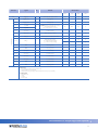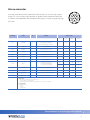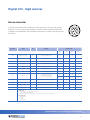
1
Industrial
CCD Cameras
Using the trigger
and the digital I/Os
Users
User Manual
Manual
Content
Introduction...............................................................................................................................................................................................3
Getting started.........................................................................................................................................................................................4
Trigger input - hardware and timing..........................................................................................................................................5
Digital I/Os - USB cameras................................................................................................................................................................6
Digital I/Os - FireWire cameras.......................................................................................................................................................9
Digital I/Os - GigE cameras............................................................................................................................................................12
Programming examples with IC Imaging Control®........................................................................................................13
Industrial CCD Cameras – Using the trigger and the digital I/Os
Introduction
In addition to a number of other applications, The Imaging Source USB, FireWire and GigE CCD cameras are also
used for industrial purposes. Most of these applications require a trigger input and general purpose digital I/Os.
These features are provided by all USB cameras whose product code contains a "BU" (e.g. DMK 21BU04, DFK
41BU02.H, etc.), all FireWire cameras whose product code contains a "BF" (e.g. DMK 31BF03-Z, DBK 41BF02, etc.)
and all GigE cameras whose product code contains a "BG" (e.g. DMK 21BG04, DBK 41BG02.H, etc.).
The trigger input of all these cameras is available via a BNC connector and thus very easy to access. The access of
the digital I/Os depends very much on the application. Therefore, basically all USB and FireWire cameras offer a pin
header that can be accessed through a hole in the cameras backplane. Please note: GigE cameras do not provide
this pin header.
For all users who prefer to access the digital I/Os using an external connector, The Imaging Source offers cameras
with a 12-pin Hirose connector on the camera's backplane. The product code of these cameras ends with the
suffix ".H" (e.g. DMK 21BU04.H, DFK 41BF02.H, DBK 31BG03.H, etc.).
This manual describes the use of all The Imaging Source USB, FireWire and GigE CCD cameras that provide an
external trigger in addition to digital I/Os.
Industrial CCD Cameras – Using the trigger and the digital I/Os
Getting started
The following steps describe the use of the most commonly used digital
input - the trigger input:
• Setup the camera as described in the Getting Started document that
accompanies the camera.
• Install the software IC Capture as described in the Getting Started
document.
• Make sure that the camera works correctly with IC Capture.
• Connect a trigger source that creates a positive pulse to the cameras BNC
connector as shown at the right hand side. The height of the pulse may lie
between 3.3 and 12 V.
• Enable the trigger mode by clicking Device > Properties... > Device >
Enable (please see the images below). If you see the dialog Activation
External Trigger, please click "Disable all property automations..." Then,
please set all camera parameters according to the requirements of your
application. Please find these parameters in the Device Properties dialog
(Device > Properties...):
Industrial CCD Cameras – Using the trigger and the digital I/Os
Trigger input - hardware and timing
The trigger input of The Imaging Source USB, FireWire and GigE CCD cameras is opto-coupled. It permits positive
trigger pulses with any amplitude between 3.3 and 12 V (24 V using a series resistance of 1 kOhm). If you intend to
apply higher pulses please make sure that the current lies between the limits of 3 to 12 mA.
1 kOhm
R = 820 Ohm
R = 820 Ohm
24V
Trigger_in
Trigger_in
12 V
The Imaging Source USB, FireWire and GigE CCD cameras offers two different modes of operation:
Free running: The cameras generate a stream of up to 60 images/s depending on their resolution. To considerably reduce the amount of data, the frame rate may be reduced to 30, 15, 7.5 or 3.75 images/s. The exposures length
can be set in the range of 100 µs to 30 s via software. Please note, however, that the camera's clock generator
determines the actual moment of exposure. Thus, it cannot be controlled externally, but measurable using the
strobe output. Therefore, this mode of operation is called "free running".
Trigger: The cameras offer a trigger input to determine the moment of exposure. The exposure begins 4.8 µs after
the occurrence of a trigger pulse. The length of the exposure in the range of 100 µs to 30 s can be set via software.
The duration of the image readout is the reciprocal of the current frame rate. Once the image readout has finished, the camera is able to accept a new trigger pulse at any time.
4.8 µs
texp = 100 µs to 30 s
tro = frame rate = 1 or 1 or 1 or 1 or 1 s
60 30 15 7.5 3.75
Trigger_in
>2.5 µs
Exposure
Image readout
Industrial CCD Cameras – Using the trigger and the digital I/Os
Digital I/Os - USB cameras
Pin header
2
1
As already mentioned in the
introduction,
there are two ways to access the camera's digital I/Os: using an internal
pin header or an external Hirose connector. To access the internal pin header please open the cameras backplane.
You will find connectors as shown in the drawings on the right hand side. Please assemble a cable that fits your
15
16
application.
I/O
The pinFireWire
header consists
of 2x8 pins with a pitch of 2.00 x 2.00 mm. Please find its pinout in the table below..
Trigger_in
16
2
15
I/O
1
Trigger_in
USB 2.0
I/O PCB of The Imaging Source USB CCD cameras
Industrial CCD Cameras – Using the trigger and the digital I/Os
Connector
Signal
I/O
Remarks
Characteristics
Min
BNC
Typ
Max
Unit
Trigger_in
I
Start of exposure (optocoupler)
3.3
12.0
V
Pin 1
Trigger_in (+)
I
ditto (signal)
3.3
12.0
V
Pin 2
Trigger_in (-)
I
ditto (ground)
-
-
-
-
Pin 3
do not use
-
For future release
-
-
-
Pin 4
do not use
-
For future release
-
-
-
Pin 5
do not use
-
for future release
-
-
-
-
Pin 6
Strobe_out
O
Flash control (open drain)
24.0¹
V
Pin 7
GP_out
O
General purpose output (open drain)
24.0¹
V
GP_in
I
General purpose input,
VIH = High Level Input Voltage
VIL = Low Level Input Voltage
24.0
Pin 8
VIH
-0.3
0
0.2
VIL
I/O pin header
-
0.6
Pin 9
GND
G
External ground
-
-
-
-
Pin 10
GND
G
External ground
-
-
-
-
Pin 11
do not use
-
For future release
-
-
-
-
Pin 12
do not use
-
For future release
-
-
-
-
Pin 13
do not use
-
For future release
-
-
-
-
Pin 14
do not use
-
For future release
-
-
-
-
Pin 15
GND
G
External ground
-
-
-
-
Pin 16
GND
G
External ground
-
-
-
-
Please note:
All specifications are subject to change without notice
1 max. 0.2 A (ID) for open drain MOSFET
I/O pin legend:
G External Ground
I Input
O Output
P Power supply
Industrial CCD Cameras – Using the trigger and the digital I/Os
Hirose connector
As already mentioned in the introduction, there are two ways to access the cameras
digital I/Os: using an internal pin header or an external Hirose connector. Please find
its pinout in the table below and the position of these pins in the drawing on the right
hand side.
Connector
Signal
I/O
Remarks
9
1
2
8
10
3
4
5
2
7
12
11
3
6
Characteristics
Min
Typ
Max
Unit
Pin 1
do not use
-
Reserved, please do not use
-
-
-
-
Pin 2
GND
G
External ground
-
-
-
-
Pin 3
SPI_MISO
-
Reserved, please do not use
-
-
-
-
Pin 4
SPI_MISO
-
Reserved, please do not use
-
-
-
-
Pin 5
SPI_CS
-
Reserved, please do not use
-
-
-
-
Pin 6
SPI_CLK
-
Reserved, please do not use
-
-
-
-
Pin 7
GND
G
External ground
-
-
-
-
-
24.0
GP_in
I
General purpose input,
VIH = High Level Input Voltage
VIL = Low Level Input Voltage
0.6
Pin 8
VIH
-0.3
0
0.2
VIL
Pin 9
GP_out
O
General purpose output (open drain)
-
-
24.01
V
Pin 10
Stobe_out
O
Flash control (Open drain)
-
-
1
24.0
V
Pin 11
Trigger_in (+)
I
Start of exposure (optocoupler signal)
3.3
-
12.0
V
Pin 12
Trigger_in (-)
I
ditto ( optocoupler ground)
-
-
-
-
Please note:
All specifications are subject to change without notice
1 max. 0.2 A (ID) for open drain MOSFET.
I/O pin legend:
G External Ground
I Input
O Output
P Power supply
Industrial CCD Cameras – Using the trigger and the digital I/Os
Digital I/Os - FireWire cameras
Pin header
As already mentioned in the introduction, there are two ways to access the camera's digital I/Os: using an internal
pin header or an external Hirose connector. To access the internal pin header please open the cameras backplane.
You will find connectors as shown in the drawings on the right hand side. Please assemble a cable that fits your
application.
The pin header consists of 2x8 pins with a pitch of 2.00 x 2.00 mm. Please find its pinout in the table below.
2
1
15
FireWire
I/O
16
Trigger_in
I/O PCB of The Imaging Source FireWire CCD cameras
16
2
15
I/O
1
Trigger_in
USB 2.0
Industrial CCD Cameras – Using the trigger and the digital I/Os
Connector
Signal
I/O
Remarks
Characteristics
Min
I/O pin header
BNC
Typ
Max
Unit
Trigger_in
I
Start of exposure (optocoupler)
3.3
12.0
V
Pin 1
Trigger_in (+)
I
ditto (signal)
3.3
12.0
V
Pin 2
Trigger_in (-)
I
ditto (ground)
-
-
-
-
Pin 3
FW_PWR
P
Caution: directly connected to the power
supply of the FireWire bus
(pin 2 of the FireWire connector.)
8.0
12.0**
30.0
V
-
-
-
-
Pin 4
FW_PWR
Pin 5
do not use
-
for future release
Pin 6
Strobe_out
O
Flash control (open drain)
24.0¹
V
Pin 7
GP_out
O
General purpose output (open drain)
24.0¹
V
GP_in
I
General purpose input,
VIH = High Level Input Voltage
VIL = Low Level Input Voltage
24.0
Pin 8
VIH
-0.3
0
0.2
VIL
0.6
Pin 9
GND
G
External ground
-
-
-
-
Pin 10
GND
G
External ground
-
-
-
-
Pin 11
do not use
-
For future release
-
-
-
-
Pin 12
do not use
-
For future release
-
-
-
-
Pin 13
do not use
-
For future release
-
-
-
-
Pin 14
do not use
-
For future release
-
-
-
-
Pin 15
GND
G
External ground
-
-
-
-
Pin 16
GND
G
External ground
-
-
-
-
Please note:
All specifications are subject to change without notice
1 max. 0.2 A (ID) for open drain MOSFET
** Determined by the power supply of the FireWire bus. This value may vary considerably.
I/O pin legend:
G External Ground
I Input
O Output
P Power supply
Industrial CCD Cameras – Using the trigger and the digital I/Os
10
Hirose connector
As already mentioned in the introduction, there are two ways to access the cameras
digital I/Os: using an internal pin header or an external Hirose connector. Please find
its pinout in the table below and the position of these pins in the drawing on the right
hand side.
Connector
Signal
I/O
Remarks
9
1
2
8
10
3
4
5
2
7
12
11
3
6
Characteristics
Min
Typ
Max
Unit
Pin 1
FW-PWR
P
Caution: directly connected to the power
supply of the FireWire bus
(pin 2 of the FireWire connector.)
8.0
12.0**
30.0
V
Pin 2
GND
G
External ground
-
-
-
-
Pin 3
SPI_MISO
-
Reserved, please do not use
-
-
-
-
Pin 4
SPI_MISO
-
Reserved, please do not use
-
-
-
-
Pin 5
SPI_CS
-
Reserved, please do not use
-
-
-
-
Pin 6
SPI_CLK
-
Reserved, please do not use
-
-
-
-
Pin 7
GND
G
External ground
-
-
-
-
-
24.0
GP_in
I
General purpose input,
VIH = High Level Input Voltage
VIL = Low Level Input Voltage
0.6
Pin 8
VIH
-0.3
0
0.2
VIL
Pin 9
GP_out
O
General purpose output (open drain)
-
-
24.01
V
Pin 10
Stobe_out
O
Flash control (Open drain)
-
-
24.01
V
Pin 11
Trigger_in (+)
I
Start of exposure (optocoupler signal)
3.3
-
12.0
V
Pin 12
Trigger_in (-)
I
ditto ( optocoupler ground)
-
-
-
-
Please note:
All specifications are subject to change without notice
1 max. 0.2 A (ID) for open drain MOSFET
** Determined by the power supply of the FireWire bus. This value may vary considerably.
I/O pin legend:
G External Ground
I Input
O Output
P Power supply
Industrial CCD Cameras – Using the trigger and the digital I/Os
11
Digital I/Os - GigE cameras
Hirose connector
As already mentioned in the introduction, there are two ways to access the cameras
digital I/Os: using an internal pin header or an external Hirose connector. Please find
its pinout in the table below and the position of these pins in the drawing on the right
hand side.
Connector
Signal
I/O
Remarks
9
1
2
8
10
3
4
5
2
7
12
11
3
6
Characteristics
Min
Typ
Max
Unit
Pin 1
GigE Power Supply
P
Caution: directly connected to the power
supply of the GigE camera
12.0
12.0**
24.0
V
Pin 2
GND
G
External ground
-
-
-
-
Pin 3
SPI_MISO
-
Reserved, please do not use
-
-
-
-
Pin 4
SPI_MISO
-
Reserved, please do not use
-
-
-
-
Pin 5
SPI_CS
-
Reserved, please do not use
-
-
-
-
Pin 6
SPI_CLK
-
Reserved, please do not use
-
-
-
-
Pin 7
GND
G
External ground
-
-
-
-
-
24.0
GP_in
I
General purpose input,
VIH = High Level Input Voltage
VIL = Low Level Input Voltage
0.6
Pin 8
VIH
-0.3
0
0.2
VIL
Pin 9
GP_out
O
General purpose output (open drain)
-
-
24.01
V
Pin 10
Stobe_out
O
Flash control (Open drain)
-
-
1
24.0
V
Pin 11
Trigger_in (+)
I
Start of exposure (optocoupler signal)
3.3
-
12.0
V
Pin 12
Trigger_in (-)
I
ditto ( optocoupler ground)
-
-
-
-
Please note:
All specifications are subject to change without notice
1 max. 0.2 A (ID) for open drain MOSFET
** Determined by the power supply of the cameras power suppy. This value may vary considerably.
I/O pin legend:
G External Ground
I Input
O Output
P Power supply
Industrial CCD Cameras – Using the trigger and the digital I/Os
12
Programming examples with IC Imaging Control®
All The Imaging Source cameras are shipped with the SDK IC Imaging Control®. IC Imaging Control® removes a
lot of programming effort, since it offers many ready-to-use basic procedures.
Below are brief examples in Visual Basic to give you an idea of how to use IC Imaging Control® to control the
trigger and the digital I/Os. You can learn more about IC Imaging Control® and download sample source code at
www.imagingcontrol.com. Additionally, our support department ([email protected]) has some more
detailed programming examples available for you.
Using the trigger
The program begins by assigning the video Device (in this case the FireWire camera DMK 21BF04), defines a
VideoFormat and sets the camera's operation mode to DeviceTrigger.
After the command LiveStart, the camera is ready to shoot: the camera now waits for a trigger pulse. MemorySnapImage instructs IC Imaging Control® to put the next image (which has been captured due to the trigger
pulse) into a buffer (Memory) for further processing. Take as an example MemorySaveImage, which saves the
content of this buffer to Triggered.bmp.
Private Sub Form_Load()
ICImagingControl1.Device = "DMK 21BF04"
ICImagingControl1.VideoFormat = "Y800 (640x480)"
ICImagingControl1.DeviceTrigger = True
ICImagingControl1.LiveStart
ICImagingControl1.MemorySnapImage
' Do something with the image - for instance:
ICImagingControl1.MemorySaveImage "Triggered.bmp"
End Sub
Activating the strobe output
FireWire cameras typically have a set of properties - such as "exposure time" or "gain". IC Imaging Control® makes
these properties available in the class VCDSimpleProperty. The program begins by defining the variable
VCDProp that will later contain these properties.
Secondly, the video Device is assigned (in this case the FireWire camera DMK 21BF04) and then we define a VideoFormat. The function GetSimplePropertyContainer assigns the properties of the opened camera
to the variable VCDProp.
The command VCDProp.Switch(VCDID_Strobe) = True activates the strobe output. Therefore, after
having started the camera with LiveStart, pin 6 indicates the CCDs exposure.
Industrial CCD Cameras – Using the trigger and the digital I/Os
13
Private Sub Form_Load()
Dim VCDProp As VCDSimpleProperty
ICImagingControl1.Device = "DMK 21BF04"
ICImagingControl1.VideoFormat = "Y800 (640x480)"
VCDProp = GetSimplePropertyContainer(ICImagingControl1.VCDPropertyItems)
VCDProp.Switch(VCDID_Strobe) = True
ICImagingControl1.LiveStart
End Sub
Reading the digital input
The first three program lines are similar to those of the preceding example (Activating the strobe output). The
main difference is to be found at the programs end: The command VCDProp.OnePush VCDElement_GPIORead reads the digital inputs state, while Debug.Print VCDProp.RangeValue(VCDElement_GPIOIn) indicates this state in terms of a debug output.
Private Sub Form_Load()
Dim VCDProp As VCDSimpleProperty
ICImagingControl1.Device = "DMK 21BF04"
VCDProp = GetSimplePropertyContainer(ICImagingControl1.VCDPropertyItems)
VCDProp.OnePush VCDElement_GPIORead
Debug.Print VCDProp.RangeValue(VCDElement_GPIOIn)
End Sub
Setting the digital output
The first three program lines are similar to those of the preceding example (Reading the digital input). The main
difference is to be found at the end of the programs: The command VCDProp.RangeValue sets the variable
VCDElement_GPIOOut to 0, whereupon VCDProp.OnePush VCDElement_GPIOWrite copies the
content of this variable (0 in our case) to the digital output.
Private Sub Form_Load()
Dim VCDProp As VCDSimpleProperty
ICImagingControl1.Device = "DMK 21BF04"
VCDProp = GetSimplePropertyContainer(ICImagingControl1.VCDPropertyItems)
VCDProp.RangeValue(VCDElement_GPIOOut) = 0
VCDProp.OnePush VCDElement_GPIOWrite
End Sub
Industrial CCD Cameras – Using the trigger and the digital I/Os
14
Headquarters: The Imaging Source Europe GmbH
Sommerstrasse 36, D-28215 Bremen, Germany
Phone: +49 421 33591-0
North & South America: The Imaging Source, LLC
6926 Shannon Willow Rd, S 400, Charlotte, NC 28226, USA
Phone: +1 704-370-0110
Asia Pacific: The Imaging Source Taiwan Co. Ltd.
6F-1, No.230, Sec.3, Ba-De Road,, Taipei City 10555, Taiwan
Phone: +886 2-2577-1228
www.theimagingsource.com
All product and company names in this document may be trademarks and tradenames of their
respective owners and are hereby acknowledged.
The Imaging Source Europe GmbH cannot and does not take any responsibility or liability for any
information contained in this document. The source code presented in this document is exclusively
used for didactic purposes. The Imaging Source does not assume any kind of warranty expressed or
implied, resulting from the use of the content of this document or the source code.
The Imaging Source Company reserves the right to make changes in specifications, function or design
at any time and without prior notice.
Last update: July 2009
Copyright © 2008 The Imaging Source Europe GmbH
All rights reserved. Reprint, also in parts, only allowed with permission of .
The Imaging Source Europe GmbH.
All weights and dimensions are approximate. Unless otherwise specified the lenses shown in the
context of cameras are not shipped with these cameras.
Industrial Cameras - Users Manual
15