1
Autonomous Systems Lab
Prof. Dr. Roland Y. Siegwart
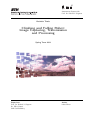
Bachelor Thesis
Climbing and Falling Robot:
Image Capturing, Transmission
and Processing
Spring Term 2011
Supervisors
Prof. Dr. Roland Y. Siegwart
Dr. Gilles Caprari
PhD Paul Beardsley
Author
Lukas Pfirter
III
Abstract
This thesis deals with the camera that is mounted on the Paraswift robot.
The latter is a wall climbing and base jumping robot which can climb a wall,
deploy a paraglider on the wall and then fly down and safely land on the
ground.
The camera is mounted on a pan/tilt mechanism. It is used to capture
images and send these to a laptop on the ground, along with the pan/tilt
angles of the camera for every image. A panoramic image is created on the
laptop out of the image material by also using the pan/tilt angle information.
This thesis especially looks at the enhancement and speeding up of the
panorama creation process by using the pan/tilt angle information as an
addition to the images.
V
Acknowledgements
Hereby I thank my supervisors Dr. Gilles Caprari and Dr. Paul Beardsley for
guiding me through this thesis and for their support. I have been given the
opportunity to learn a lot and work interdisciplinary in different engineering
areas.
Special thanks go to the Disney Research Lab Zurich for the financial sponsoring of the required equipment and the Autonomous Systems Lab, especially Prof. Dr. Roland Y. Siegwart, for allowing this thesis to be enforced
at the lab and for providing the working environment.
Further thanks go to Urs and Sebastian for their support from Switzerland
while I’m working on this thesis from abroad.
I also thank Dominik, Dario, Lukas, Marco, Pascal and Michael from the
team Paraswift who worked with me for one year and during my work on
this thesis.
Finally I thank Dr. Matthew Brown and Markus Achtelik for answering
some questions and giving hints.
Contents
VII
Contents
Abstract
. . . . . . . . . . . . . . . . . . . . . . . . . . .
III
Acknowledgements . . . . . . . . . . . . . . . . . . . . . .
V
1
Introduction
11
1.1
Context & motivation . . . . . . . . . . . . . . . . . . . .
11
1.2
System overview . . . . . . . . . . . . . . . . . . . . . . .
12
1.3
Goals . . . . . . . . . . . . . . . . . . . . . . . . . . . . .
12
1.4
Work packages & time schedule . . . . . . . . . . . . . . .
13
1.5
Preliminary studies . . . . . . . . . . . . . . . . . . . . . .
13
1.5.1
State of the art . . . . . . . . . . . . . . . . . . . . . . . .
13
1.5.2
Capture in motion . . . . . . . . . . . . . . . . . . . . . .
15
1.5.3
Panorama creation basics . . . . . . . . . . . . . . . . . .
16
1.6
Structure of the report . . . . . . . . . . . . . . . . . . . .
17
2
Capturing Concept
19
2.1
Angle of view . . . . . . . . . . . . . . . . . . . . . . . . .
19
2.2
Amount of images . . . . . . . . . . . . . . . . . . . . . .
20
2.3
Camera motion . . . . . . . . . . . . . . . . . . . . . . . .
21
2.4
Panorama process optimization . . . . . . . . . . . . . . .
23
3
Camera & Transmission
25
3.1
Camera requirements . . . . . . . . . . . . . . . . . . . . .
25
3.2
Camera choice . . . . . . . . . . . . . . . . . . . . . . . .
26
3.3
AXIS M1011-W . . . . . . . . . . . . . . . . . . . . . . . .
27
3.3.1
Lens . . . . . . . . . . . . . . . . . . . . . . . . . . . . . .
27
3.3.2
Wireless connection . . . . . . . . . . . . . . . . . . . . . .
28
3.3.3
Board modifications . . . . . . . . . . . . . . . . . . . . .
28
3.4
Serial data transmission . . . . . . . . . . . . . . . . . . .
29
VIII
Contents
4
Mechanical Design
31
4.1
Requirements . . . . . . . . . . . . . . . . . . . . . . . . .
31
4.2
Dimensions & design . . . . . . . . . . . . . . . . . . . . .
32
4.3
Material, manufacturing & weight . . . . . . . . . . . . . .
32
4.4
Optimization & implementation . . . . . . . . . . . . . . .
33
5
Computer Vision
37
5.1
Existing software . . . . . . . . . . . . . . . . . . . . . . .
37
5.1.1
One-click stitching . . . . . . . . . . . . . . . . . . . . . .
37
5.1.2
Command-line stitching with Panorama Tools . . . . . . . .
38
5.2
Software development: PanoProcessor . . . . . . . . . . . .
39
5.2.1
Main routine . . . . . . . . . . . . . . . . . . . . . . . . .
39
5.2.2
Additional classes . . . . . . . . . . . . . . . . . . . . . . .
40
5.2.3
Microcontroller program . . . . . . . . . . . . . . . . . . .
41
5.2.4
Using PanoProcessor . . . . . . . . . . . . . . . . . . . . .
42
6
Experiments & Results
43
6.1
Captures . . . . . . . . . . . . . . . . . . . . . . . . . . .
43
6.2
PTStitcherNG test images . . . . . . . . . . . . . . . . . .
43
6.3
Stitching with PTStitcherNG
. . . . . . . . . . . . . . . .
44
6.3.1
Required stitching time . . . . . . . . . . . . . . . . . . . .
46
6.3.2
Ceiling . . . . . . . . . . . . . . . . . . . . . . . . . . . .
47
7
Conclusion & Outlook
49
8
Directories
51
8.1
List of abbreviations . . . . . . . . . . . . . . . . . . . . .
51
8.2
Bibliography . . . . . . . . . . . . . . . . . . . . . . . . .
52
8.3
List of figures . . . . . . . . . . . . . . . . . . . . . . . . .
53
Contents
IX
9
Appendix
55
A
Lists, tables and illustrations
57
A.1
Time schedule . . . . . . . . . . . . . . . . . . . . . . . .
57
A.2
Flight dynamics . . . . . . . . . . . . . . . . . . . . . . . .
58
B
Data sheets, technical specifications
59
B.1
LENSAGON BVM5015014 lens . . . . . . . . . . . . . . .
59
B.2
AXIS M1011-W camera . . . . . . . . . . . . . . . . . . .
60
B.3
AXIS M10 camera series comparison
. . . . . . . . . . . .
61
B.4
Antenova Rufa 2.4 Ghz antenna A5839 . . . . . . . . . . .
62
C
Software installation
63
C.1
MacPorts . . . . . . . . . . . . . . . . . . . . . . . . . . .
63
C.2
OpenCV
. . . . . . . . . . . . . . . . . . . . . . . . . . .
63
C.3
Panotools / Libpano . . . . . . . . . . . . . . . . . . . . .
64
C.4
Hugin . . . . . . . . . . . . . . . . . . . . . . . . . . . . .
65
D
Panoramas
67
D.1
Capture 201104281_1 . . . . . . . . . . . . . . . . . . . .
67
D.2
Capture 201104281_2 . . . . . . . . . . . . . . . . . . . .
68
D.3
PTStitcherNG testimages . . . . . . . . . . . . . . . . . .
69
D.4
Capture 20110513 . . . . . . . . . . . . . . . . . . . . . .
71
E
Source Code
73
E.1
main.cpp . . . . . . . . . . . . . . . . . . . . . . . . . . .
73
E.2
SerialConnection.h . . . . . . . . . . . . . . . . . . . . . .
77
E.3
FileManipulator.h . . . . . . . . . . . . . . . . . . . . . . .
77
E.4
Utils.h . . . . . . . . . . . . . . . . . . . . . . . . . . . . .
78
E.5
BufferManager.h . . . . . . . . . . . . . . . . . . . . . . .
78
E.6
CamHandler.h . . . . . . . . . . . . . . . . . . . . . . . .
79
E.7
Settings.h . . . . . . . . . . . . . . . . . . . . . . . . . . .
79
E.8
Microcontroller program . . . . . . . . . . . . . . . . . . .
80
Introduction
11
1 Introduction
1.1 Context & motivation
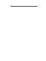
The goal of the 2010/11 ETH Focus Project1 Paraswift2 is to develop a wall
climbing and base jumping robot. Paraswift climbs outdoor building walls
and deploys a paraglider, used to safely land on the ground.
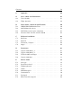
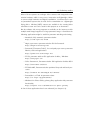
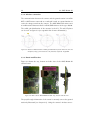
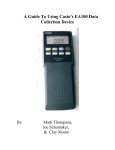
Robots often carry around cameras for inspection and other purposes. Likewise does the Paraswift robot; in this case not for inspection but for the
attraction of a crowd which looks at the robot in action (see Fig. 1.1 / 1.2).
This thesis deals with the camera which gets mounted on the Paraswift robot
and the involved mechanisms, electronics and Computer Vision algorithms.
The camera is used to create panoramic images from the robots view.
Figure 1.1: Illustration of Paraswift
show by Maurizio Nitti,
DRZ
Figure 1.2: Paraswift show, 21. June
2011 at ETH Zurich
My personal motivation for this thesis is the variety of different disciplines
that are involved. It covers interesting engineering disciplines like mechanics,
electronics, computer science/vision and also practical experiments.
1
2
Project-based work with other students in the 4th/5th semester of Mechanical Engineering Bachelor at ETH Zurich.
See [12] for more information about Paraswift.
12
1.2 System overview
1.2 System overview
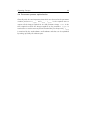
As visible on figure 1.3, the Paraswift robot contains a ground plate with
vortex adhesion mechanism and gearwheels for driving on the wall (a), a
paraglider and it’s deployment mechanism (b) and a shell mounted on a
protective frame (c). The core of the on-board electronics is a Skybotix3
CoaX microcontroller.
Figure 1.3: Paraswift robot system overview
1.3 Goals
The following goals were set after the kickoff meeting of this thesis. The
minimum "must-have"-goals are:
•
Provide an attractive image/video that can be projected on a big
screen during presentations of the Paraswift wall climbing and base
jumping robot to attract the audience.
•
Realise a system containing a camera, video transmitter and receiver,
to send image-/video-material from the robot to the ground station,
during climbing and flying phase.
•
Develop mechanisms to stabilize the camera and remove unwanted
effects on the image-/video-material.
•
Create one or more panorama images by stitching together multiple
single images. Use existing stitching software algorithms.
The "nice-to-have"-goals are:
•
Create multiple panorama images in the robots climbing phase, one
about every 5-10 meters.
3
More information on: http://www.skybotix.ch
Introduction
•
13
Map the camera view from the flight phase to the panorama image of
the corresponding height, previously taken in the climbing phase.
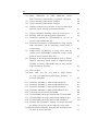
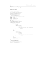
1.4 Work packages & time schedule
Work Breakdown Structure
Bachelor Thesis, LP
The presented thesis has been structured into 3 main stages: Preliminary
studies, concept and implementation.
Climbing and Falling Robot: Image
Capturing, Transmission and Processing
Organisation
Preliminary studies
Documentation
Goal setting
Events
Contacting People
Research: State of the art,
optical characteristics,
possible problems
Camera types
(finding a camera)
Concept
Analyse robot motion
Camera specifications
Develop camera mounting
Software algorithms
Tests / test stand
Implementation
Programming
Mechanics:
camera mounting
Electronics: sensors, µC,
wireless transmission
Implement into Paraswift
Figure 1.4: Work breakdown structure of the thesis
The stages and work packages (see figure 1.4) have been assigned into a
project schedule (see appendix A.1). Together with the detailed schedule,
the following milestones have been defined:
•
16.04.2011: Design of camera mounting complete, necessary parts
ordered.
•
29.04.2011:
Panorama images collected from test stand or test
Paraswift robot drop, begin of code-implementation.
•
16.05.2011: First stitch of panorama images with stitching software.
1.5 Preliminary studies
1.5.1 State of the art
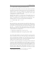
A lot of mobile robotic applications use cameras as sensors and to record image/video material (some examples: [10], [11] and [14]). In radio controlled
aeroplane toys, cameras are used to transmit the view of the aeroplane directly to the person controlling the aeroplane. This gives to the "pilot" a
feeling as if he was sitting in the planes cockpit (FPV - First Person View)4 .
4
For an example see: http://www.immersionrc.com
14
1.5 Preliminary studies
Most of these systems use analogue video cameras with integrated transmission hardware, which is easy to use, inexpensive and lightweight. When
it comes to high resolution and digital transmission, I could not find a camera/transmitter system that is made for live transmission on a lightweight
flying device. Wireless (WiFi) cameras are available in the security/video
surveillance sector and can be used for this purpose as an alternative.
On the software side, many programs are available on the internet to stick
multiple small images together to a large panoramic image. I found that the
following applications might be useful for panorama stitching and viewing:
•
Autostitch, fully automatic panorama stitcher
http://cvlab.epfl.ch/~brown
•
Hugin, open-source panorama stitcher GUI for Panotools
http://hugin.sourceforge.net
•
Panotools ("Panorama Tools"), free and partly open source panorama
libraries, tools and applications
http://panotools.sourceforge.net
•
PTGui, panorama stitcher GUI application for Mac / Windows
http://www.ptgui.com
•
Calico Panorama 2, Panorama stitcher GUI application for Mac OS X
http://www.kekus.com/beta
•
PTStitcherNG, Panorama stitcher optimized for speed and batch processes
http://webuser.fh-furtwangen.de/~dersch/
•
Panosalado 2, a Flash 10 panorama viewer
http://os.ivrpa.org/panosalado/
•
Windows Live Photo Gallery, photo gallery application with panorama
functionality
http://explore.live.com/windows-live-photo-gallery
A few of these applications have been evaluated (see chapter 5.1).
Introduction
15
1.5.2 Capture in motion
This chapter describes a few camera and capturing related issues that are
important when using a camera that is in motion during image/video capturing.
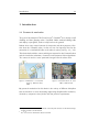
The amount of light going through the camera opening is called exposure
and is measured in lux seconds. The opening is called shutter - the duration
during which the shutter is open is called exposure time and is controlled
by the shutter speed. With a short exposure time it is possible to record a
moving object without motion blur, but can create a dark image because
less light gets on the camera’s image sensor. A longer exposure time allows
to record a scene over a period of time, although moving objects may get
motion blur (see figure 1.5 for an example). [2] [3] [4]
In order to create good looking panorama images, motion blur has to be
avoided. Chapter 2.3 shows an approach to do so.
Figure 1.5: Example image with motion
blur [3]
Figure 1.6: Example image showing the
effect of rolling shutter [6]
Figure 1.7: Example image (interlaced)
[9]
Figure 1.8: Example image (progressive
scan) [9]
Cameras with global shutter record every point / pixel of a frame in the
same period of time. In contrast rolling shutter (also called line scan) scans
across a frame line by line either vertically or horizontally over a period of
16
1.5 Preliminary studies
time. This effect gets visible when recording moving objects or moving the
camera while recording: The scene changes slightly for every recorded line
which results in a distorted image (see figure 1.6 for an example). [6]
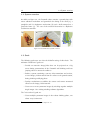
Interlacing (interlaced video) is a method of refreshing odd and even horizontal lines of a video alternately. It allows doubling of the perceived frame
rate but requires playback equipment that supports de-interlacing (mainly
CRT screens). The progressive scan method scans an image line by line
going from top to bottom, treating odd and even lines equally. See figures
1.7 and 1.8 for examples. [8] [9]
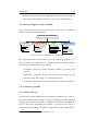
1.5.3 Panorama creation basics
For captured image material to stitch successful to a panoramic image,
panoramic heads are used in photography (see [13] for examples). These
special camera mountings rotate the camera exactly around it’s focal point
to eliminate parallax error in the stitching process. When not rotating the
camera around it’s focal point, the ratio of the camera translation to the
scene distance should be kept small for the error to be negligible.
On the software side, stitching together image material can take a long time
(depending e.g. on the image amount, the image resolution and the used
hardware). Most panorama creation applications detect control points on
all images and compare images with each other by comparing the matching
of their control points. This process requires an overlapping area of the
images (50% should be sufficient as a guideline) and images with adequate
texture so control points (e.g. edges) can be detected. By not knowing
initially which image is located about where in the final panorama, the
control points of all images have to be compared with the control points
of all other images. See figure 1.9 for a control point comparison illustration.
Figure 1.9: Control point comparison illustration from Autopano Pro GUI
http://www.kolor.com/panorama-software-autopano-pro-interface.html,
requested: 25/06/2011
Introduction
17
1.6 Structure of the report
The report is structured into the following chapters. The Introduction gives
a brief intro about this thesis. It is followed by the "Capturing Concept"
which explains the way images will be captured. The chapter "Camera
& Transmission" explains about the electronics used in this project. In the
chapter "Mechanical Design", the design of the pan/tilt camera mounting is
documented. The chapter "Computer Vision" contains software evaluation
and documentation of the coding work. In the chapter "Experiments &
Results", the field experiments and their outcome are presented. Finally the
chapter "Conclusion & Outlook" concludes the thesis and contains ideas of
further use and improvements of the work of this thesis.
Capturing Concept
19
2 Capturing Concept
This chapter describes the concept for the creation of panorama images.
2.1 Angle of view
The angle of view of the camera lens (sometimes also referred to as field of
view) defines how large the angular visual extent of the camera is. [5] The
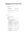
maximum angle of view has been derived in the following way:
A persons face in the audience of the Paraswift show should have a vertical
resolution of around 22 pixels (see figure 2.1) at a distance of 15 m to the
camera. With an average face height of 20 cm a proportional calculation
leads to the fact that 480 pixels (assumed vertical camera resolution) would
display ≈ 4.5 m vertically.
h
Figure 2.1: Example portrait with 22 pixels "face resolution".
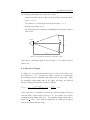
Figure 2.2 shows the basic arrangement of the geometrical calculation.
Thus the minimal vertical angle of view is:
α=
H
l
With:
=
yres ·h
fres ·l
=
480·20cm
22·15m
= 16.7◦
fres = 22 (vertical face resolution in pixels)
yres = 480 (vertical camera resolution in pixels)
20
2.2 Amount of images
The following assumptions were taken into account:
•
Distance from the camera to the face in the audience during the whole
show: l = 15 m
•
The distance l is much larger than the face height: l >> h
•
Average face height: 20 cm
•
The used camera has a resolution of 640x480 pixels and thus an aspect
ratio of 4:3
Camera
Face
α
h
H
l
Figure 2.2: Geometrical calculation of the angle of view.
This leads to a horizontal angle of view of about α ≈ 20◦ with an aspect
ratio of 4:3.
2.2 Amount of images
In chapter 2.1, the required horizontal angle of view of the camera lens
was derived as ≈ 20◦ .
Because the robot is mostly on a horizontally
linear shaped wall, the maximum image width angle is about 180◦ . With
an overlapping image width angle of 10◦ (50%) per image, the required
amount of images horizontally is derived as follows:
nimgh =
total angle
angle of view − overlapping angle
=
180◦
20◦ −10◦
= 18
In the same way, it is possible to calculate the required amount of images
vertically, with a vertical angle of view of ≈ 16◦ (see chapter 2.1) and the
overlapping image height angle of 8◦ . The maximum image height angle is
chosen as
9
16
· 180◦ ≈ 100◦ with the supposition of a 16:9 cinema aspect
ratio for the final panorama image.
Capturing Concept
nimgv =
21
total angle
angle of view − overlapping angle
=
100◦
16◦ −8◦
≈ 12
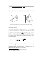
Figure 2.3 shows the amount of images that have to be captured horizontally
and vertically. In total, one panorama image will consist of about 18 · 12 =
216 images.
a)
b)
wall
18 ...
1
1
wall
2
...
2
...
180°
...
100°
12
Figure 2.3: Amount images to be captured (a) horizontally and (b) vertically
2.3 Camera motion
The Paraswift robot reaches a climbing speed of ≈ 15 cm
s and will climb
at least 12 meters up the wall.1 I defined that every 4 meters there should
be issued one panorama image, made of the 216 single images. The time
available to create the images is t =
4m
0.15 m
s
= 26.7 s assuming the image
material can be captured during climbing and the Paraswift robot climbs at
full speed. The camera will move with the following angular velocity under
the assumptions above:
ω ≈ (nimgv · (180◦ − 20◦ ) + (100◦ − 16◦ )) ·
ω ≈ (12 · 160◦ + 84◦ ) ·
π
180◦
·
1
26.7s
= 1.36
π
180◦
rad
s
·
1
t
Assuming the camera is the reference system, objects at a distance of 15 m
will move with ≈ 15 m
s relative to the camera. When recording a moving
scene, motion blur (see chapter 1.5.2) can become a problem. It is in this
case an unwanted, but also removable effect.2 To avoid motion blur, the
shutter speed of the camera has to be fast enough.
1
2
According to the requirements of the Paraswift robot in [12]
See [1] (P. 141) and [15] for details
22
2.3 Camera motion
The shutter speed can be calculated in the following way. Assumptions:
•
An object moves horizontally with 15 m
s
•
Horizontal resolution of the camera: 640 pixels
•
Distance from the camera to the object: 15 m
•
Horizontal angle of view of the camera lens: 20◦
The horizontal resolution of 640 pixels depicts 2 · 15 m · tan(10◦ ) ≈ 5.3 m
of a scene with moving objects. Therefore one pixel depicts 8.28 mm. If an
15 m
s
8.28 mm ≈ 1800 pixels per second.
1
1
15 m
/8.28 mm ≈ 1800 s in order to have a
s
object moves with 15 m
s , it moves with
Thus the required shutter time is
zero pixel motion blur (no motion blur at all).
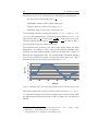
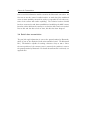
The Paraswift robot and hence the camera also swings during the down
flying phase. According to earlier collected and analysed Paraswift video
material3 , the robot swings primarily around the tilt/pitch axle4 . Figure 2.4
illustrates the swinging over time. The experimentally determined swinging
curve has a maximum at around 1 second after robot drop of 68◦ and a
angle [°]
minimum at about 2.25 seconds after robot drop of −18◦ .
70
60
50
40
30
20
10
0
-10
-20
0.00
0.50
1.00
1.50
2.00
2.50
time [s]
Figure 2.4: Swinging angle of the down flying Paraswift robot around the tilt/pitch axle
This motion requires the camera to be able to move at least |68◦ |+|−18◦ | =
86◦ around the tilt/pitch axle in order to always keep one point focused. With
the defined minimal tilt/pitch motion of 100◦ in chapter 2.2, this request is
fulfilled.
3
4
Paraswift
video
P1000393_Steuern_1915_19.mov
2010-12-09_1_CamLukasG_Steuern_Hoenggerberg
See Appendix A.2 for a description of the different axles
from
testing
session
Capturing Concept
23
2.4 Panorama process optimization
Generally said, the two important times which are relevant for the panorama
creation process are tcapture and tstitch . tcapture is the required time to
capture all the images required for one full panorama image. tstitch is the
time required to stitch the images together to the panorama. tcapture is
restricted to a certain extent to prevent motion blur (see chapter 2.3). tstitch
is restricted by the used software and hardware and thus can be optimized
by tuning especially the software part.
Camera & Transmission
25
3 Camera & Transmission
3.1 Camera requirements
The requirements for the camera have been defined as follows:
•
Camera / transmitter total weight: < 100 g
•
Camera resolution of at least 640x480 pixels
•
Digital transmission (or analogue with a frequency other than 2.4 Ghz)
•
Horizontal angle of view of 20◦ or removable objective
(see chapter 2.1)
•
Fit in available space (see chapter 4.1 and figure 4.5)
•
Shutter time of at least
1
10 800
s to avoid motion blur
(see chapter 2.3)
The camera weight was already chosen to be < 100 g at an early stage of
the Paraswift project. For a flying robot it is very important that the weight
is kept low.
The resolution requirement was set because this is a resolution which could
be achieved with a cheap analogue camera/transmitter too, to have this
option open as a backup plan.
A transmission frequency of the camera other than 2.4 Ghz is required to
avoid interference with the radio that controls the Paraswift robot. This does
mainly apply to analogue transmitters, because they spread their signal with
bad affect on other devices on this frequency, as I was told by people working
with similar components. A digital transmission can have any frequency as
it wont interfere with the robot’s radio.
26
3.2 Camera choice
3.2 Camera choice
After searching the internet for many different cameras and testing a possible
analogue camera that was already available at the lab, the decision was made
to focus on a WiFi surveillance camera because they seem to work well for the
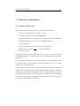
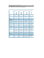
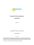
purpose. Table 3.1 shows a closer selection of WiFi cameras which are light
and meet the requirements listed in chapter 3.1. Usually, the camera’s case
can be taken apart and the removed PCB with the camera image sensor and
the transmitter will only have a small fraction of the total camera weight
including it’s case. Table 3.1 lists cameras with the weight promoted by
the manufacturer, including the camera’s case and wall mounting. In the
column tS,min the minimum shutter times are listed. The Power column
displays the camera’s power consumption, the column VGA FPS lists the
maximum frames per second at VGA resolution (640x480 pixels).
Table 3.1: Selection of possible digital WiFi cameras
Camera
Asante SecureNet
Voyager I
Vivotek IP7137
Vivotek PT7137
AXIS M1011-W
Price
120 USD
Weight
309 g
VGA FPS
30
Power
10 W
200 EUR
300 CHF
265 CHF
165 g
271 g
94 g
30
30
30
4W
8W
7W
Figure 3.1: WiFi camera AXIS M1011-W
http://www.axis.com/products/cam_m1011w/index.htm,
requested: 25/6/2011
tS,min
unk.
1
15000
1
15000
1
5000
s
s
s
Camera & Transmission
27
3.3 AXIS M1011-W
The decision fell on the AXIS M1011-W camera (which can be seen on figure
3.1), mainly because it is very lightweight and was available at local internet
stores. The two big uncertainties were the weight of the camera’s PCB after
removal of the unneeded housing and weather the lens mounting allowed to
insert a lens with the desired angle of view. The weight turned out to be
only 25 g after removal of the housing which is a great result compared to
the overall weight of 94 g promoted by the manufacturer. Exchanging the
lens was no problem as well because the PCB of the AXIS M1011-W holds a
common M12x0.5mm thread ("S-mount"). Only for heavy lenses the plastic
thread feels insufficient because it is loose when the lens is put inside.
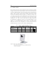
3.3.1 Lens
The lens "Lensagon BVM5015014" (see figure 3.2) was chosen to be used
for the camera. The angle of view can be adjusted to a desired value between
19◦ and 41◦ . With a weight of 35 g the lens is heavy compared to plastic
lenses (≈ 2 g) but the quality is better due to better quality materials used.
A detailed datasheet of the lens can be found in appendix B.1.
Figure 3.2: Lensagon BVM5015014 lens
http://www.lensation.de/de/shop.html?page=shop.product_
details&product_id=172, requested: 25/6/2011
The images captured with this lens seemed to have inappropriate colours as
visible in chapter 6 and appendix D. This problem was not further worked
on due to lack of time but should be fixable by e.g. colour adjustments of
the images after capturing.
dBi
5
-15
28
X
3.3 AXIS M1011-W
Y
-35
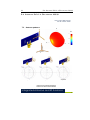
3.3.2 Wireless connection
The communication between the camera and the ground station is 2.4 GHz
WiFi. A WiFi router connected to a notebook is used as a ground station to
receive the images sent from the camera. The AXIS M1011-W camera uses
an unidirectional Antenova Rufa 2.4 GHz SMD Antenna of the type A5839.
The radial gain distribution of the antenna in the XY, ZY and XZ planes
can be seen on figure 3.3 (see appendix B.4 for more information).
XY plane
ZY plane
XZ plane
Figure 3.3: Antenova A5839 antenna: Radial gain distribution pattern in the XY, ZY and
XZ planes, http://www.antenova.com/?id=744, requested: 25/6/2011
Patterns show combined polarisations
measured on reference board A5839-U1
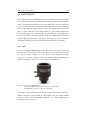
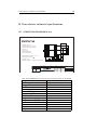
3.3.3 Board modifications
Integrated Antenna and RF Solutions
Figure 3.4 shows the top, bottom and side view of the AXIS M1011-W4
Product Specification AE020157-N
camera board.
Figure 3.4: WiFi camera AXIS M1011-W PCB: Top, bottom and side view
The pan/tilt angle information of the servos is currently sent to the ground
station by Bluetooth (see chapter 3.4). Using the camera’s wireless connec-
Camera & Transmission
29
tion to send this information would economise the Bluetooth connection. An
idea was to use the camera’s audio interface to send data (the unsoldered
areas are most probably reserved for audio, see appendix B.3 for other versions of the camera with audio capability). The technical section of AXIS
has been contacted to ask about possibilities of modifying the AXIS camera
board to achieve this but the contact to a technician has never been reached.
Due to this and also due to lack of time, this idea has been dropped.
3.4 Serial data transmission
The pan/tilt angle information is sent to the ground station by Bluetooth,
which is part of the Skybotix CoaX microcontroller board. The Bluetooth
RX / TX should be capable of reaching a distance of up to 100 m. Once
the servo position of the camera servos is renewed, the position is sent to
the ground station by Bluetooth. For details about how this is achieved, see
appendix E.8.
Mechanical Design
31
4 Mechanical Design
The design of the pan/tilt mounting for the camera is described in this
chapter.
4.1 Requirements
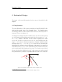
The outer dimensions of the camera mounting are basically limited by the
shell and the ground plate of the Paraswift robot. The length between
the damping cushions of the Paraswift robot where the camera is placed in
between is 20 cm (see figure 4.5).
According to the design concept of the final case1 , the camera can be placed
on the Paraswift robot pointing away from the shell at an angle of α = 36◦
or α = 72◦ , relative to the wall. For the centre of gravity to be closer
to the wall and also to reduce the force on the camera holding arm, the
angle α = 36◦ has been chosen (see figure 4.1). Together with the robot’s
swinging angles of β1 = −68◦ and β2 = 18◦ relative to the wall during the
flying phase (see chapter 2.3 for the derivation of the angle), the camera has
to be able to turn |α| + |β1 | = 104◦ around the tilt axle, in order to keep one
point in sight during the swinging of the robot. The rotation extent around
the pan axle has been defined to be 180◦ so the camera can catch as much
image material for a panorama as possible while the robot is on a flat wall.
β1
α
n
β2
z
Figure 4.1: Placement of the camera on the Paraswift robot
1
See [12] for more information about the Paraswift design concept.
32
4.2 Dimensions & design
4.2 Dimensions & design
At the time of the camera mounting design, the camera AXIS M1011-W
itself was ordered but not yet available. This required an estimation of the
camera PCB’s maximum dimensions, because they were not clear at order
time (see chapter 3.2). Figure 4.2 shows the outer dimensions of the chosen
camera.
Figure 4.2: Outer dimensions of AXIS M1011-W camera
http://www.axis.com/m1011w/, requested: 13/6/2011
The camera PCB was estimated to be relatively large compared to the small
image sensor on it. To rotate it on a pan/tilt mechanism requires a lot of
space. Due to the latter and also due to lack of time, a mechanism has
been designed in which the camera does not turn around the focal point of
it’s lens, which is fairly easier to design. Not turning the lens around it’s
focal point when capturing images can cause parallax error in the process of
stitching those images together to a panorama. This error mainly occurs on
short distances between the lens and recorded objects. Because this project
deals with comparatively long distances to recorded objects, this parallax
AXISerror
M1011-W
- Wireless Network Camera
was disregarded.
20 NOVEMBER, 2008
4.3 Material, manufacturing & weight
The camera mounting is based on lightweight parts made of bendable Peraluman aluminium and also rapid prototyping print material (characteristics
similar to PVC). These materials were basically chosen because manufacturing dealings in this field were already set up within the Paraswift project.
Mechanical Design
33
The weight of the camera is 94 g according to the manufacturer (see appendix B.2 for the camera’s specifications). After removing the plastic housing of the camera, the weight of the camera PCB alone turned out to be 25 g.
The total weight of the camera PCB and the pan/tilt mechanism reached
≈ 130 g. A detailed listing of all components and the corresponding weights
can be viewed in table 4.1.
Table 4.1: Weight of all used components
Component
AXIS M1011-W camera PCB
LENSAGON BVM5015014 lens
Servos 3x
Bracket 1
Cam mount
Part of rotating axis
Carbon rod
Ball bearings 5x
Bearing shaft top
Screws, glue
Servo bearing mount
top mount part
Servo mounting parts 12x
Density
2.7 g/cm3
1.4 g/cm3
1.4 g/cm3
15 g/m
1.4 g/cm3
1.4 g/cm3
1.4 g/cm3
1.4 g/cm3
Weight
25 g
35 g
33 g
9.0 g
1.0 g
2.0 g
2.25 g
2.5 g
7.9 g
8g
1.3 g
1.9 g
0.32 g
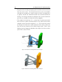
4.4 Optimization & implementation
The CAD model of the camera mounting was drawn into the Paraswift concept model. The maximum outer dimensions of the camera’s PCB were
drawn as cross-sections because they were unclear at the time of the mounting design. Once the manufacturing of the first design (see Fig. 4.3) was
done, some disadvantages became clear after the camera was received and
fixed onto the mounting, which required a redesign (see Fig. 4.4). The following changes were done to the camera mounting to reach the optimized
final design:
•
The gearwheels were removed due to the clearance between the teeth.
Instead of using gearwheels, the joint of the servo has directly been
used as the turning points of the pan axle (same design as for the tilt
axle). This design increases precision in the positioning of the camera.
1
See appendix B.1 for lens specifications
34
4.4 Optimization & implementation
•
Big parts made of rapid prototyping print material have been removed
from the joint section. The material turned out to be too bendable
and thus was avoided to be used for parts on which a bending force
is applied. Instead the aluminium bracket was extended around the
bearing. This change lowered the oscillation of the camera around the
pan axle by a multiple and made this effect negligible.
•
The weight of the used lens of 35 g turned out to generate too much
side load on the plastic S-mount thread on the camera PCB, which
originally carries a lens with a weight of ≈ 2 g. The heavier lens caused
the image to be blurred in certain positions of the camera where the
lens axle was not normal to the camera image sensor. Thus a lens
holding arm was designed to distribute the weight of the lens to other
parts of the camera’s PCB.
Figure 4.3: Camera mounting CAD model: Design I
Figure 4.4: Camera mounting CAD model: Design 2
Mechanical Design
35
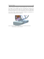
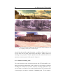
A final mechanism to swing the camera mounting into a safe area before
the landing of the Paraswift robot has conceptually been designed (see
figure 4.5) and has also been taken into account in table 4.1. Nevertheless
the whole mechanism has not been implemented into the Paraswift robot
due to lack of time. Instead, the pan/tilt mechanism was mounted on a
test stand for experiments (see chapter 6).
Figure 4.5: Damping cushions on the bottom of the Paraswift robot with the
camera pan/tilt mechanism inbetween.
Computer Vision
37
5 Computer Vision
This chapter lies a focus on the software components used to create the
panoramic images out of the captured image material. The course of action
was to test a few existing software components and then chose the one that
fits best as the core component of panoramic image creation. The self-made
part was decided to do the automated routine and call the application that
creates the panorama.
5.1 Existing software
When searching the web for panorama stitcher applications, the amount of
results is immense. Although only a few are easy to use and free of charge.
Some of the applications introduced in chapter 1.5.1 have been installed on
a MacBook with Mac OS X 10.6.6 for testing. Installation protocols can be
found in appendix C. A closer look was taken on "Autostitch", "Windows
Live Photo Gallery" and "PTStitcherNG". Benchmarking of these applications can be found in chapter 6.2, appendix D shows panorama images
stitched with them.
5.1.1 One-click stitching
The application Autostitch1 is available for download as a demo version.
It stitches panoramas pretty fast and matches features well. As the name
says, Autostitch operates automatically after choosing source images. It has
a lot of optional settings for fine-tuning. In a likewise way as Autostitch,
Windows Live Photo Gallery2 also stitches panorama images with one click
and is completely free of charge. Compared to Autostitch, it has no options
to fine-tune the panorama creation process.
Both of these programs work by one click in the GUI and don’t support
command-line usage in the free versions available on the internet.
1
2
More information on: http://cvlab.epfl.ch/~brown/
More information on: http://explore.live.com/windows-live-photo-gallery/
38
5.1 Existing software
5.1.2 Command-line stitching with Panorama Tools
The application PTStitcherNG3 can be used to stitch images to panoramas
along with the information in which direction the camera was pointing when
taking the image. It has a lot of settings for the panorama and for every
single input image. PTStitcherNG and other command-line tools like cpfind
or PToptimizer are included in PanoTools4 .
Stitching images together to a panorama with PTStitcherNG works in the
following way: Images are stored together with a so called project file in a
folder. See appendix D.3 for an example image series along with a corresponding project file. The project file starts with the following lines:
p f 1 w1500 h900 v360
m
n" t i f f "
i0
Where p describes the output panoramic image with f that defines the projection mode, w and h that set the size of the output image, v which stands
for the field of view and n that defines what image type should be created
(jpg, tiff, ...). The m-line defines global options such as i which defines
the interpolation mode. Every input image that is included in the panorama
requires another line in the project file:
o f 3 w648 h972 n" Image0 . JPG" r 0 p0 y0 v89 . 2 4
o f 3 w648 h972 n" Image1 . JPG" r 0 . 3 4 p −0.31 y51 . 7 5 v89 . 2 4
o f 3 w648 h972 n" Image2 . JPG" r 1 . 6 8 p0 . 9 4 y118 . 3 8 v89 . 2 4
...
Lines starting with o signalize an image line with f that sets the projection
mode, w and h that set the size of the input image, n which defines the
name of the input image and finally r, p, y and v which set roll, pan, tilt
angles and the field of view of the lens. A more detailed explanation of these
settings and more possible parameters can be found on [7].
PanoTools is a collection of programs to stitch images fast and in automated
environments. While PTStitcherNG is used to stitch images to a panorama,
cpfind can be used to find control points on images and PToptimizer can be
used to optimize these control points before using PTStitcherNG for the final
panorama creation. When testing PTStitcherNG, I found that it is hard to
see what values are allowed for certain parameters. Fine tuning is a matter
3
4
More information on: http://webuser.hs-furtwangen.de/~{}dersch/
More information on: http://panotools.sourceforge.net
Computer Vision
39
of trial and error because of insufficient description for the unfamiliar end
user. Nevertheless PTStitcherNG has been chosen for the panorama stitching process because it is very fast5 , command-line accessible and available
as freeware.
5.2 Software development: PanoProcessor
The self made part of the software used in this thesis, "PanoProcessor", is
responsible for grabbing images and pan/tilt information from the Paraswift
robot, modify this data and execute the required command-line applications
from the PanoTools collection. It basically grabs images through the webinterface of the camera and saves the corresponding pan/tilt angles that are
fetched through Bluetooth. After the grabbing process, the pan/tilt data
is adjusted and fed to the command-line programs cpfind, PToptimizer and
PTStitcherNG along with the captured images.
The software is written on a MacBook Pro running Mac OS X 10.6.6 and the
IDE Xcode 3.2.5. All of the self-made software is written in object oriented
C++ and should be transferable to a Windows or Linux platform with only
little effort. The whole software source code can be obtained here:
http://balp.paraswift.ch/PanoProcessor_v1.0_source.zip
The following chapters roughly explain the code of Pano Processor.
5.2.1 Main routine
The whole program should be easily understandable by only looking at the
file main.cpp which can be found in Appendix E.1. The file starts with
the inclusion of libraries and the creation of needed subclass objects. A
command-line menu is realised with a switch statement wherein the char
"mode" can be set to the desired mode. The following program modes can
be chosen:
•
mode g: This is the image grabbing mode. A serial connection is set
up and serial data is gathered. When a particular signal is received
over serial, an image is grabbed from the camera and the corresponding
pan/tilt info is saved to a text file (also see chapter 5.2.2). For the
5
See chapter 6.3.1 for benchmarking of PTStitcherNG
40
5.2 Software development: PanoProcessor
grabbing mode to work, the Paraswift program on the CoaX board
needs additional software (see chapter 5.2.3).
•
mode d: The debugging mode does almost what mode "g" does,
except that images are not saved, received data from serial is printed
to the console and the program will stop running after 20 seconds.
•
mode p: Entering this mode will use PTStitcherNG to create a
panorama of the grabbed images only with the use of the saved pan/tilt
camera angles. This is the fastest panorama creation mode (see chapter 6.3.1).
•
mode f: This mode will use PTStitcherNG to create a panorama like
mode p. Supplementary, also control points on images are located
with cpfind and used in the panorama creation process. After entering
the mode f it is possible to chose to compare control points only on
nearby images or to compare control points from every image with
every other image. The latter option obviously takes up a multiple of
the time as only comparing nearby images.
•
mode s: The "series"-mode can create an image-series illustrating the
stitching process using PTStitcherNG with pan/tilt camera angles only.
PTStitcherNG is executed for every image and creates a panorama of
the series. Finally also a video is created using ffmpeg6 .
•
mode q: Choosing this mode will quit the program.
After one mode of the program is executed, the menu will always prompt
for the next mode to be executed until the mode q is chosen to exit.
5.2.2 Additional classes
To keep main.cpp clearly arranged a number of classes have been written to
take over certain parts of the program. The header files of these classes can
be found in appendix E. A short explanation of all classes is given below:
•
BufferManager is responsible for the storage of data received over
the serial connection.
The received data can be passed to the
function processInput which will look for strings in the format of:
[identifier@value]. An example is: [[email protected]] which would mean that
6
More information on: http://www.ffmpeg.org
Computer Vision
41
the yaw angle is at a value of 0.2. The data is saved into a data array
of the type double.
•
CamHandler can grab images from the AXIS M1011-W camera over
it’s web interface using the command-line program wget7 . Images
are saved to the working directory. This function should be easily
modifiable to work with other cameras.
•
FileManipulator contains functions to manipulate text files of which
the most are PanoTools compatible project files. There are a few
functions to convert project files from one PanoTools format to another
one, e.g. convert a PTStitcherNG compatible project file to a cpfind
compatible project file. Other functions go through project files line by
line and adjust image lines to e.g. centre the panorama or cut images
which lie out of the boundaries of the panorama which would cause
errors while feeding them to PTStitcherNG.
•
SerialConnection takes care of establishing a connection to a serial
device and returning the received data. It is used within PanoProcessor
to establish the connection to the Bluetooth adapter which will talk to
the Skybotix CoaX microcontroller on board of the Paraswift robot.
•
Utils contains a few minor function for data type conversion and string
manipulation.
•
Settings holds values of all the needed settings for the PanoProcessor
environment. These are e.g. paths of used command-line applications, paths to used text files and settings for the camera and serial
connection.
5.2.3 Microcontroller program
For PanoProcessor to work, a small piece of software has to be added to
the Paraswift software on the CoaX microcontroller. A required function
is "imagecapture" which has to be included above the main() function. In
the main()-function, "imagecapture" can be called while rotating about the
pan/tilt angles. The required code can be seen in appendix E.8.
7
More information on: http://www.gnu.org/software/wget/
42
5.2 Software development: PanoProcessor
5.2.4 Using PanoProcessor
The following steps have to be taken to use PanoProcessor:
•
Obtain the source code of PanoProcessor from:
http://balp.paraswift.ch/PanoProcessor_v1.0_source.zip
•
Change the file settings.h: Edit all options to fit your environment.
The default options set the working directory to ˜/Desktop/Capture,
in which images are saved and processed.
•
Compile the code with gcc or C++.
•
Make sure that the CoaX board has the needed code included, which
can be found in appendix E.8.
PanoProcessor can be used without the hardware connected, to process
earlier captured image series. A few series of images to test PanoProcessor
can be obtained from here:
http://balp.paraswift.ch/Capture_Tests.tar.gz
Experiments & Results
43
6 Experiments & Results
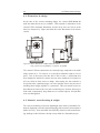
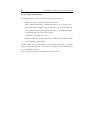
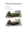
6.1 Captures
All capture experiments have been made with the AXIS M1011-W camera
mounted on a test stand, as depicted on figure 6.1.
Figure 6.1: Capture equipment including camera on a test stand
Images have been collected at various locations in Zurich for stitching tests.
The first captures have been made without saving the corresponding pan/tilt
angle information of the camera to test one-click stitching applications. Results can be seen in appendix D.1 and D.2. When comparing figures D.1
and D.2 or figures D.3 and D.4 with each other, it can be seen that certain
parts of the images are stitched differently.
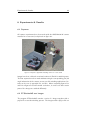
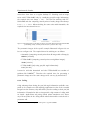
6.2 PTStitcherNG test images
The program PTStitcherNG contains a series of 7 images together with a
project file to test the stitching process. The images and the project file can
44
6.3 Stitching with PTStitcherNG
be found in appendix D.3. These images have been stitched with PTStitcherNG, Autostitch and Windows Live Photo Gallery. Resulting panoramic
images can be seen in appendix D.3.
Required time for stitching
9.00 s
8.00 s
7.00 s
6.00 s
5.00 s
4.00 s
3.00 s
2.00 s
1.00 s
0.00 s
Autostitch (Win)
Windows Live (Win)
PTStitcherNG (Win)
PTStitcherNG Test Images
Figure 6.2: Stitching with and without position information
Comparing the required stitching time for this image series of one-click stitching applications and PTStitcherNG (see figure 6.2) it can be seen that PTStitcherNG is the fastest. The difference of the required stitching time from
one-click stitchers compared to PTStitcherNG should increase non linear
by an increasing number of images because one-click applications normally
compare all images with all other images (see chapter 1.5.3 for details).
6.3 Stitching with PTStitcherNG
To get used to the input parameters of PTStitcherNG, the project file of
the PTStitcherNG testing image series has been taken as a basic for a series
of images captured with the camera on the test stand. The images have
been aligned by setting the corresponding pan/tilt angles manually (trial and
error). The result can be seen on figure D.9 of appendix D.4. After this
manual alignment, the pan/tilt angles of the capture have been converted
with PanoProcessor (see chapter 5.2) to look about as with the manual
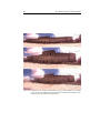
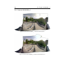
alignment (see figure D.10 of appendix D.4). This result is imperfect because of parallax error (small scene distance) and an unoptimized pan/tilt
mechanism. After optimizing the mechanical part of the mechanism (see
chapter 4.4) the resulting panoramic images generated only by the use of
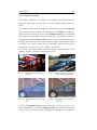
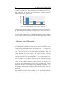
the pan/tilt angle information looked quite better (see figure 6.3). Further
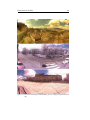
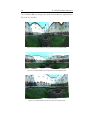
optimization was done to the software part by including comparison of control points of nearby images which improved the resulting images again (see
figure 6.4).
Figure 6.4 shows panoramas generated by the use of pan/tilt information
and by comparing control points on nearby images. (The same panoramas
Experiments & Results
45
Figure 6.3: Panoramas stitched by PTStitcherNG by the use of pan/tilt angle information
only
46
6.3 Stitching with PTStitcherNG
Figure 6.4: Panoramas stitched by PTStitcherNG by using pan/tilt angle information and
by comparing control point of nearby images
stitched by only pan/tilt angle information are visible on figure 6.3.) It can
be seen that even by using control point matching on nearby images the
stitching is not yet perfect. Further optimization that could be done to the
panorama creation process is discussed in chapter 7.
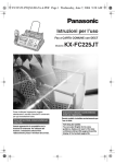
6.3.1 Required stitching time
The most important result of stitching images with PTStitcherNG by providing pan/tilt angle information of the camera for every image is the short
stitching time compared to one-click automatic stitching applications. Figure 6.5 shows an example of the required stitching time for an image series
of 267 images, each with a resolution of 640x480 pixels. These measure-
Experiments & Results
47
ments have been done on a regular desktop PC. Stitching such an image
series with PTStitcherNG only by considering pan/tilt angle information,
the required time was always < 10 s. The time for stitching with PTStitcherNG and also comparing control points of nearby images was always:
1 min < t < 2 min. When stitching the same series with Autostitch, the
required time was around 10 min.
Figure 6.5: Required time for stitching an image series with Autostitch and PTStitcherNG
(considering nearby control points and servo position data only)
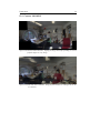
The panoramic images of the specific example illustrated in figure 6.5 can
be seen on figure 6.6. The required times for stitching are as follows:
•
Autostitch (comparing control points from all images with all images):
689.5 s (11.5 min)
•
PTStitcherNG (comparing control points on neighbour images):
78.0 s (1.3 min)
•
PTStitcherNG (only using pan/tilt angle information):
5.3 s (0.1 min)
It must be said that Autostitch and also PTStitcherNG use random algorithms like RANSAC1 . Therefore the required time for generating a
panoramic image out of the same image series can vary by around 10 %.
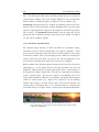
6.3.2 Ceiling
A big advantage from having the pan/tilt angle information available compared to for example one-click stitching applications is that if the recorded
images have low textures, they will still be placed according to their pan/tilt
information. Examples for this are images with a big amount of ceiling with
no clouds. Applications only using control points sometimes can’t detect
any of these points in the ceiling which makes them unable to stitch such a
panorama well.
1
More information on: http://en.wikipedia.org/wiki/RANSAC
48
6.3 Stitching with PTStitcherNG
Figure 6.6: Stitching of 267 images with Autostitch (top), PTStitcherNG by comparing
control points on neighbour images (middle) and with PTStitcherNG only by
using pan/tilt angle information (bottom)
Conclusion & Outlook
49
7 Conclusion & Outlook
The output of this thesis is very satisfying. An easy to use application has
been produced, which creates good looking panoramic images in a very competitive time. The fastest panorama creation with the developed PanoProcessor software is even ten times faster than with a common application
even though the final panorama is not flawless, but still nice to look at.
All the "must-have"-goals have been reached with good results. The "niceto-have"-goals were not reached due to lack of time and maybe they have
been set while being overconfident. Conceptually the flying phase of the
Paraswift robot has been looked at but the implementation into the robot
and also experiments using the Paraswift wall climbing and base jumping
system never happened. Instead at least an analogue camera with a wide
screen lens was mounted on the robot at a Paraswift show to get at least
some expertise of the flying phase.
Working with PanoTools and especially PTStitcherNG was not always easy.
The lack of documentation required a trial and error approach to find out
how these programs work. Nevertheless it must be said that the PanoTools
newsgroups were a good drop-in centre to receive support. In return the
PanoTools applications are available as freeware and seem to be the only
existing command-line panorama environment that is freeware.
Finally, working on this thesis was mostly very diversified because it is a
multidisciplinary thesis in which mechanics, electronics, optics and software
development are united. It was a challenge to overlook all the different parts
and not invest too much time into one thing while disregarding something
else.
Due to the fact that this thesis only makes use of freeware applications, it
can easily be distributed to other people to work on it and do further research
with the output of this thesis as a starting point.
50
Below is a list of possible improvements to the hard- and software part of
this thesis:
•
Currently the servos of the pan/tilt joints are controlled by the CoaX
microcontroller. They are set to a desired position (no feedback),
which is also the position used to send to the laptop ground station
as pan/tilt angles for the corresponding captured image. By adding
encoders or potentiometers to the joints and connecting them to the
microcontroller, the positioning error could be minimized which would
result in a much better panorama image that is created only by the
information of the pan/tilt angles.
•
By turning the pan/tilt camera mounting around the focal point of the
camera lens, the parallax error could be removed. This would allow for
indoor capture, as the distance to the scene could be very small. This
has not been done because it was not necessary for the used scene
distance of > 15 m.
•
Other applications than PanoTools could be used for the same purpose, like e.g. Autostitch MATLAB version which supports usage in
a programmable / scripting environment (conditions of usage would
have to be clarified because it is not freeware).
•
Looking at the flying phase of the robot would be a nice addition to
have more possibilities during the Paraswift show. Using the camera
while flying for the localization of the current height by comparing
the view with previously generated panoramas (panoramas generated
while being in climbing mode) is an example.
When slightly changed, the ideas and software code of this thesis could also
be used in different fields than entertainment like e.g. video surveillance
or inspection robotics. In video surveillance it is important to have good
quality image material to recognize happenings on the recorded image/video
material for a specific area of the image but at the same time it is helpful to
see the whole image. By using the pan/tilt mounted camera, only important
scene details could be updated while still having a wide screen overview of
the rest of the image. Also inspection robotics need to see details while for
the person controlling the inspection robot it is good to have an overall view
as well. The previously recorded material could be stored and added to the
overall view while details would get updated continuously.
Directories
51
8 Directories
8.1 List of abbreviations
ASL
Autonomous Systems Lab
DRZ
Cathode ray tube
DRZ
Disney Research Zurich
ETHZ
Federal Institute of Technology Zurich
FPS
Frames per second
FPV
First Person View
GUI
Graphical user interface
IDE
Integrated development environment
IR
Infrared
LCD
Liquid crystal display
OOP
Object-oriented programming
PCB
Printed circuit board
PVC
Polyvinyl chloride (thermoplastic polymer)
RANSAC
RC
Random Sample Consensus
Radio Controlled
TFT
Thin-film transistor
VGA
Video Graphics Array
52
8.2 Bibliography
8.2 Bibliography
[1] Handbuch der Bildverarbeitung. Stemmer Imaging, 2010.
[2] http://en.wikipedia.org/wiki/Exposure_(photography),
requested: 04/06/2011.
[3] http://en.wikipedia.org/wiki/Motion_blur, requested: 04/06/2011.
[4] http://en.wikipedia.org/wiki/Shutter_(photography),
requested: 04/06/2011.
[5] http://en.wikipedia.org/wiki/Angle_of_view,
requested: 04/26/2011.
[6] http://en.wikipedia.org/wiki/Rolling_shutter,
requested: 05/06/2011.
[7] http://webuser.hs-furtwangen.de/ dersch/, requested: 06/06/2011.
[8] http://en.wikipedia.org/wiki/Interlaced_video,
requested: 23/04/2011.
[9] http://www.axis.com/products/video/camera/progressive_scan.htm,
requested: 23/04/2011.
[10] E. Altug, J.P. Ostrowski, and C.J. Taylor. Control of a quadrotor
helicopter using dual camera visual feedback. The International Journal
of Robotics Research, 24(5):329, 2005.
[11] T. Kanade, O. Amidi, and Q. Ke. Real-time and 3d vision for autonomous small and micro air vehicles. In Decision and Control, 2004.
CDC. 43rd IEEE Conference on, volume 2, pages 1655–1662. IEEE,
2004.
[12] Team Paraswift. World’s first base jumping robot, 2011.
[13] 360 precision. Precision Panoramic Heads, may 2011.
http://www.360precision.com.
[14] ME Rentschler, J. Dumpert, SR Platt, SI Ahmed, SM Farritor, and
D. Oleynikov. Mobile in vivo camera robots provide sole visual feedback
for abdominal exploration and cholecystectomy. Surgical endoscopy,
20(1):135–138, 2006.
[15] Q. Shan, J. Jia, and A. Agarwala. High-quality motion deblurring from
a single image. In ACM SIGGRAPH 2008 papers, pages 1–10. ACM,
2008.
53
8.3 List of figures
1.1
Illustration of Paraswift show by Maurizio Nitti, DRZ . . .
11
1.2
Paraswift show, 21. June 2011 at ETH Zurich . . . . . . .
11
1.3
Paraswift robot system overview . . . . . . . . . . . . . .
12
1.4
13
1.7
Work breakdown structure of the thesis . . . . . . . . . . .
Example image with motion blur [3] . . . . . . . . . . . .
Example image showing the effect of rolling shutter [6] . .
Example image (interlaced) [9] . . . . . . . . . . . . . . .
1.8
Example image (progressive scan) [9] . . . . . . . . . . . .
15
1.9
Control point comparison illustration from Autopano
1.5
1.6
Pro
GUI
15
15
15
http://www.kolor.com/panorama-software-
autopano-pro-interface.html, requested: 25/06/2011 . . . .
16
2.1
Example portrait with 22 pixels "face resolution". . . . . .
19
2.2
Geometrical calculation of the angle of view. . . . . . . . .
20
2.3
Amount images to be captured (a) horizontally and (b)
vertically . . . . . . . . . . . . . . . . . . . . . . . . . . .
2.4
Swinging angle of the down flying Paraswift robot around
the tilt/pitch axle . . . . . . . . . . . . . . . . . . . . . .
3.1
21
WiFi
camera
AXIS
22
M1011-W
http://www.axis.com/products/cam_m1011w/index.htm,
requested: 25/6/2011 . . . . . . . . . . . . . . . . . . . .
3.2
Lensagon
BVM5015014
26
lens
http://www.lensation.de/de/shop.html?page=shop.product_
details&product_id=172, requested: 25/6/2011 . . . . . .
3.3
Antenova
A5839
antenna:
Radial
gain
27
distri-
bution pattern in the XY, ZY and XZ planes,
http://www.antenova.com/?id=744, requested: 25/6/2011
3.4
4.1
28
WiFi camera AXIS M1011-W PCB: Top, bottom and side
view . . . . . . . . . . . . . . . . . . . . . . . . . . . . .
28
Placement of the camera on the Paraswift robot . . . . . .
31
54
4.2
Outer
dimensions
of
AXIS
M1011-W
camera
http://www.axis.com/m1011w/, requested: 13/6/2011 . .
32
4.3
Camera mounting CAD model: Design I . . . . . . . . . .
34
4.4
Camera mounting CAD model: Design 2 . . . . . . . . . .
34
4.5
Damping cushions on the bottom of the Paraswift robot
with the camera pan/tilt mechanism inbetween. . . . . . .
35
6.1
Capture equipment including camera on a test stand . . . .
43
6.2
Stitching with and without position information . . . . . .
44
6.3
Panoramas stitched by PTStitcherNG by the use of
pan/tilt angle information only . . . . . . . . . . . . . . .
6.4
45
Panoramas stitched by PTStitcherNG by using pan/tilt
angle information and by comparing control point of
nearby images . . . . . . . . . . . . . . . . . . . . . . . .
6.5
46
Required time for stitching an image series with Autostitch and PTStitcherNG (considering nearby control
points and servo position data only) . . . . . . . . . . . .
6.6
47
Stitching of 267 images with Autostitch (top), PTStitcherNG by comparing control points on neighbour images
(middle) and with PTStitcherNG only by using pan/tilt
angle information (bottom) . . . . . . . . . . . . . . . . .
48
A.1 Time schedule . . . . . . . . . . . . . . . . . . . . . . . .
57
A.2 Roll, pitch and yaw axes used in flight dynamics http://en.wikipedia.org/wiki/Flight_dynamics, requested: 5/06/2011 . . . . . . . . . . . . . . . . . . . . .
58
D.1 Panorama 20110428_1 stitched with Autostitch . . . . . .
67
D.2 Panorama 20110428_1 stitched with Windows Live . . . .
67
D.3 Panorama 20110428_2 stitched with Autostitch . . . . . .
68
D.4 Panorama 20110428_2 stitched with Windows Live . . . .
68
D.5 Test image series from PTStitcherNG . . . . . . . . . . . .
69
D.6 PTStitcherNG test images stitched with PTStitcherNG . .
70
D.7 PTStitcherNG test images stitched with Windows Live . .
70
D.8 PTStitcherNG test images stitched with Autostitch . . . .
70
D.9 Stitched with PTStitcher, aligning the images manually
by finding out correct pan/tilt angles for every image . . .
71
D.10 Stitched with PTStitcher, using pan/tilt information coming from the microcontroller . . . . . . . . . . . . . . . . .
71
Appendix
9 Appendix
55
56
Lists, tables and illustrations
57
A Lists, tables and illustrations
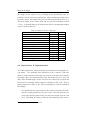
A.1 Time schedule
Time Schedule
Bachelor Theses LP
Month:
Week:
March
10
11
12
April
13
14
15
16
May
17
Organisation
Documentation
Goal setting
Events
Contacting People
Preliminary studies
Research
Camera types
Concept
Analyse robot motion
Camera specifications
Develop cam. mounting
Software algorithms
Tests / test stand
Implementation
Programming
Mechanics
Electronics
Implement into Paraswift
Figure A.1: Time schedule
18
19
20
21
22
23
24
58
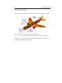
A.2 Flight dynamics
A.2 Flight dynamics
The following image shows descriptions of the axles used in flight dynamics:
Figure A.2: Roll, pitch and yaw axes used in flight dynamics
http://en.wikipedia.org/wiki/Flight_dynamics, requested: 5/06/2011
For camera systems, the axle descriptions pan and tilt are often used where
pan refers to yaw and tilt to pitch.
Data sheets, technical specifications
59
B Data sheets, technical specifications
B.1 LENSAGON BVM5015014 lens
1
2
3
4
5
6
7
Sensing Area: 1/3"
Focal Length: 5.0~15.0mm
Back Focal Length: 6.85mm
F/NO: 1.4
Iris: Fixed
Optical Distortion
Lens Construction:
8 Field Angle (horizontal): 41° ~19°
9 Focus Extent: 20 cm 10 Weight : 34g
11Feature / Function : Megapixel IR corrected
TOLERANCE
UNIT
mm
MATERIAL
SCALE
5:1
X.XX
X.X
X.
ø 0.05
ø 0.10
ø 0.30
DO NOT SCALE DRAWING
SHEET
BORDER
DIMENSION TOLERANCE
A4
1 OF 1
NAME
QUANTITY
DATE
TYPE
PART NO.
DRAWING
BY
REV.NO
A
DATA BASE
CHECKED
TITLE
Lensagon BVM5015014
BY
APRROVED
BY
CONFIDENTIAL
Table B.1: BVM5015014 lens specifications from www.lensation.de, 18.06.2011
Image format
Mount type
Megapixel
Vari-focal
Focal length (max)
Back focal length
Aperture (F)
M.O.D.
Angle of View (diag.)
Angle of View (diag. max.)
Zoom
Focus
Iris
Weight
1/3 inch
S-Mount (M12x0.5)
1 MP
Yes
5 mm (15 mm)
6.85 mm
1.4
0.2 m
41 ◦
19 mm
manual with lock
manual with lock
fixed
35 g
60
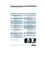
B.2 AXIS M1011-W camera
B.2 AXIS M1011-W camera
40705/EN/R1/1009
www.axis.com
Technical Specifications – AXIS M10 Network Camera Series
Camera
Models
Image sensor
Lens
Light sensitivity
Shutter time
Pan/Tilt/Zoom
AXIS M1011: Wired interface
AXIS M1011-W: Wired and wireless interface
AXIS M1031-W: Wired and wireless interface, PIR sensor,
illumination LED, audio
AXIS M1054: Power over Ethernet, PIR sensor, illumination LED,
audio, I/O ports
AXIS M1011/M1011-W/M1031-W: 1/4’’ progressive scan RGB
CMOS, AXIS M1054: 1/4” progressive scan RGB CMOS
AXIS M1011/M1011-W/M1031-W: 4.4 mm: 47° view*, F2.0,
fixed iris, fixed focus
AXIS M1054: 2.9 mm: 84° view*, F2.0, fixed iris, fixed focus
*horizontal angle of view
AXIS M1011/M1011-W/M1031-W: 1-10000 lux, F2.0
AXIS M1054: 1.2 - 100000 lux, F2.0
AXIS M1031-W/M1054: 0 lux with illumination LED on
AXIS M1011/M1011-W/M1031-W: 1/5000 s to 1/4 s
AXIS M1054: 1/24500 s to 1/6 s
AXIS M1054: Digital PTZ, preset positions, guard tour
Video
Video compression
H.264 (MPEG-4 Part 10/AVC), Motion JPEG
AXIS M1011/M1011-W/M1031-W: MPEG-4 Part 2 (ISO/IEC
14496-2)
Resolutions
AXIS M1011/M1011-W/M1031-W: 640x480 to 160x120
AXIS M1054: 1280x800 to 160x90
Frame rate
H.264: 30 fps in all resolutions
Motion JPEG: 30 fps in all resolutions
AXIS M1011/M1011-W/M1031-W, MPEG-4 Part 2: 30 fps in
all resolutions
Video streaming Multiple, individually configurable streams in H.264 and
Motion JPEG, as well as MPEG-4 Part 2 with
AXIS M1011/ M1011-W/M1031-W
Controllable frame rate and bandwidth
VBR/CBR H.264, MPEG-4 Part 2
Image settings
Compression, color, brightness, sharpness, contrast, white
balance, exposure control, exposure zones, backlight
compensation, fine tuning of behavior at low light, rotation
Text and image overlay, Privacy mask
AXIS M1054: Mirroring
Audio (AXIS M1031-W & AXIS M1054)
Audio streaming Two-way
Audio
compression
Audio in/out
AAC-LC 8/16 kHz, G.711 PCM 8kHz, G.726 ADPCM 8 kHz
Configurable bit rate
Built-in microphone and speaker
Network
Wireless interface AXIS M1011-W/M1031-W: IEEE 802.11g/b
Invisibly integrated antenna
Security
Password protection, IP address filtering, HTTPS** encryption,
digest authentication, user access log
AXIS M1011-W/M1031-W: WEP 64/128 bit, WPA/WPA2-PSK
IPv4/v6, HTTP, HTTPS**, QoS Layer 3 DiffServ, FTP, SMTP,
Supported protocols
Bonjour, UPnP, SNMPv1/v2c/v3(MIB-II), DNS, DynDNS, NTP,
RTSP, RTP, TCP, UDP, IGMP, RTCP, ICMP, DHCP, ARP, SOCKS
System integration
Open API for software integration, including the ONVIF
Application
specification available at www.onvif.org, as well as VAPIX® from
Programming
Axis Communications, specifications available at www.axis.com
Interface
Support for AXIS Video Hosting System (AVHS) with One-Click
Camera connection
Intelligent video Video motion detection, active tampering alarm
AXIS M1031-W/M1054: Audio detection
Alarm triggers
Intelligent video
AXIS M1031-W/M1054: PIR sensor
AXIS M1054: PIR sensor, external input
Alarm events
File upload via FTP, HTTP and email
Notification via email, HTTP and TCP
AXIS M1031-W/M1054: Activation of illumination LED, audio
clip playback, AXIS M1054: external output activation
Video buffer
AXIS M1011/M1011-W/M1031-W: 16 MB pre- and post alarm
AXIS M1054: 25 MB pre- and post alarm
General
Processor and AXIS M1011/M1011-W/M1031-W: ARTPEC-B, 64 MB RAM, 32
memory
MB Flash, AXIS M1054: ARTPEC-3, 128 MB RAM, 128 MB Flash
Power
4.9 – 5.1 V DC, max. 6.5 W
AXIS M1054: Power over Ethernet IEEE 802.3af Class 2 (max.
6.49W)
Connectors
DC jack, RJ-45 10BASE-T/100BASE-TX
AXIS M1054: 1 alarm input and 1 output
PIR sensor
AXIS M1031-W/M1054: Passive infrared (PIR) motion sensor
with configurable sensitivity. Max range: 6 m
Illumination LED AXIS M1031-W/M1054: White illumination LED: 1 W
Operating
conditions
Approvals
Weight
Included
accessories
Video
management
software (not
incl.)
Humidity 20 - 80% RH (non-condensing)
AXIS M1011/M1011-W/M1031-W: 0 – 50 °C (32 – 122 °F)
AXIS M1054: 0 – 40 °C (32 – 113 °F)
AXIS M1011: EN 55022 Class B, EN 55024, EN 61000-3-2,
EN 61000-3-3, EN 60950-1, FCC Part 15 Subpart B Class B,
VCCI Class B, ICES-003 Class B, C-tick
AXIS M1011-W/M1031-W: EN301489-1, EN301489-17,
EN300328, EN 60950-1, FCC Part 15 Subpart B and C Class B,
RSS-210, C-TICK, TELEC, KCC, SRRC
AXIS M1054: EN 55022 Class B, EN 61000-3-2, EN 61000-3-3,
EN 55024, FCC Part 15 Subpart B Class B, ICES-003 Class B,
VCCI Class B, C-tick AS/NZS CISPR 22, KCC Class B, EN 60950-1
Power supply: EN 60950-1, cCSAus
AXIS M1011: 94 g (0.21 lb), AXIS M1011-W: 94 g (0.21 lb)
AXIS M1031-W: 100 g (0.22 lb), AXIS M1054: 160 g (0.35 lb)
Power supply, stand and clamp, Installation Guide, CD with
installation tools, recording software and User’s Manual,
Windows decoder 1-user license
AXIS M1054: Extension for stand: 100 mm [4.0”]
AXIS Camera Station - Video management software for viewing
and recording up to 50 cameras. For more software application
via partners, see www.axis.com/products/video/software/
Dimensions
70 mm [2,8”]
More information is available at www.axis.com
95 mm [3,7”]
65 mm [2,6”]
**This product includes software developed by the OpenSSL
Project for use in the OpenSSL Toolkit. (www.openssl.org)
All cameras
41 mm [1,6”]
34 mm [1,4”]
28 mm [1”]
59 mm [2,3”]
17 mm [0,7”]
AXIS M1011/M1011-W/M1031-W
©2010 Axis Communications AB. AXIS COMMUNICATIONS, AXIS, ETRAX, ARTPEC and VAPIX are registered trademarks or trademark applications of Axis AB
in various jurisdictions. All other company names and products are trademarks or registered trademarks of their respective companies. We reserve the right
to introduce modifications without notice.
AXIS M1054
Data sheets, technical specifications
61
www.axis.com
MAY 2011
B.3
AXIS M10
camera series comparison
Axis fixed network cameras
AXIS M11
AXIS M10 Series
Image sensor
Lens
Horizontal
angle of view
Day and night
Min illumination/
light sensitivity (lux)
Video compression
Max video resolution
(pixels)
Frames per second
AXIS M1011
AXIS M1011-W
AXIS M1031-W
AXIS M1054
AXIS M1103
AXIS M1104
1/4“ progressive scan CMOS
1/4“ progressive scan CMOS
1/4“ progressive scan CMOS
1/4“ progressive scan CMOS
1/4“ progressive scan CMOS
1/4“ progressive scan CMOS
4.4 mm/F2.0
fixed iris
4.4 mm/F2.0
fixed iris
4.4 mm/F2.0
fixed iris
2.9 mm/F2.0
fixed iris
Fixed iris, CS mount
2.8 mm/F2.0
6 mm/F1.8
Fixed iris, CS mount
2.8 mm/F2.0
6 mm/F1.8
47°
47°
47°
80°
2.8 mm: 66°
6 mm: 31°
2.8 mm: 80°
6 mm: 37°
1 - 10,000
1 - 10,000
1 - 10,000
0 with LED on
1.2 - 100,000
0 with LED on
2.8 mm: 1.0 - 100,000
6 mm: 0.9 - 100,000
2.8 mm: 1.0 - 100,000
6 mm: 0.9 - 100,000
H.264
Motion JPEG
MPEG-4
H.264
Motion JPEG
MPEG-4
H.264
Motion JPEG
MPEG-4
H.264
Motion JPEG
H.264
Motion JPEG
H.264
Motion JPEG
640 x 480
640 x 480
640 x 480
1280 x 800 (1 MP)
800 x 600
1280 x 800 (1 MP)(2)
30 (640x480)
30 (640x480)
30 (640x480)
30 (1280x800)
30 (HDTV 720p)
30 (800x600)
30 (1280x800)
30 (HDTV 720p)
Two-way
Built-in mic and speaker
Two-way
Built-in mic and speaker
Audio support
Alarm in-/outputs
1/1
Motion detection
Tampering alarm
Motion detection
Tampering alarm
Motion detection
Audio detection
Tampering alarm
Motion detection
Audio detection
Tampering alarm
Motion detection
Tampering alarm
Motion detection
Tampering alarm
Security
Multi-level passwords
IP filtering
HTTPS encryption
Multi-level passwords
IP filtering
HTTPS encryption
Multi-level passwords
IP filtering
HTTPS encryption
Multi-level passwords
IP filtering
HTTPS encryption
Multi-level passwords
IP filtering
HTTPS encryption
Multi-level passwords
IP filtering
HTTPS encryption
Network
IPv4/v6, QoS
IPv4/v6, QoS
IPv4/v6, QoS
IPv4/v6, QoS
IPv4/v6, QoS
IPv4/v6, QoS
DC
PoE splitter available
DC
PoE splitter available
DC
PoE splitter available
DC
PoE IEEE 802.3af Class 2
PoE IEEE 802.3af Class 1
PoE IEEE 802.3af Class 1
Requires housing
Requires housing
Built-in PIR sensor,
illumination LED,
wireless, AVHS(1), ONVIF
Built-in PIR sensor,
illumination LED,
digital PTZ, AVHS(1),
Corridor Format™
Digital PTZ,
pixel counter,
AVHS(1), Corridor Format™
Digital PTZ,
pixel counter,
AVHS(1), Corridor Format™
Intelligent video
Power
Serial connectors
Outdoor use
Other
AVHS(1), ONVIF
Wireless, AVHS(1), ONVIF
(1) AVHS - AXIS Video Hosting System with One-Click Camera Connection; (2) 1440 x 900 (1.3 MP) scaled resolution available via VAPIX®
62
B.4 Antenova Rufa 2.4 Ghz antenna A5839
B.4 Antenova Rufa 2.4 Ghz antenna A5839
Rufa 2.4 GHz SMD Antenna
Part No. A5839 / A5887
7-3 Antenna patterns
Z
dBi
5
-15
X
XY plane
ZY plane
Y
-35
XZ plane
Patterns show combined polarisations
measured on reference board A5839-U1
Integrated Antenna and RF Solutions
4
Product Specification AE020157-N
Software installation
63
C Software installation
The following chapters list protocols of software installations which I needed
for this thesis. The installations have been done on a MacBook Pro (Intel)
using Mac OS X 10.6.6.
C.1 MacPorts
To install MacPorts on Mac OS X, the latest installation image (.dmg)
was fetched from http://www.macports.org and installed using defaults.
MacPorts is needed for most of the following software installations. This
command updates MacPorts to the latest version:
su do p o r t s e l f u p d a t e
su do p o r t −d s y n c
To install MacPorts from source:
su do p o r t i n s t a l l cmake
su do p o r t i n s t a l l b o o s t t i f f j p e g l i b p n g wxWidgets s u b v e r s i o n
openexr e x i v 2 glew m e r c u r i a l t c l a p
C.2 OpenCV
Instructions using the console (bash):
su do p o r t i n s t a l l s u b v e r s i o n
su do p o r t i n s t a l l cmake
cd / o p t
s v n co h t t p s : / / c o d e . r o s . o r g / s v n / o p e n c v / t r u n k / o p e n c v −r 3 0 5 9 ;
cd o p e n c v
su do cmake −G " U n i x ␣ M a k e f i l e s "
su do make −j 8
su do make i n s t a l l
Installation instructions were taken from: http://opencv.willowgarage.
com/wiki/Mac_OS_X_OpenCV_Port (requested: 20.04.2011).
The link
above also contains instructions about how to create a project in xCode
with openCV.
64
C.3 Panotools / Libpano
C.3 Panotools / Libpano
Instructions using the console (bash):
cd / o p t
s v n co h t t p s : / / p a n o t o o l s . s v n . s o u r c e f o r g e . n e t / s v n r o o t /
panotools panotools
cd p a n o t o o l s / t r u n k / l i b p a n o
vi bootstrap
change
LIBTOOLIZE=$ {LIBTOOLIZE:− l i b t o o l i z e }
to
LIBTOOLIZE=$ {LIBTOOLIZE:− g l i b t o o l i z e }
e x p o r t CFLAGS="−a r c h ␣ i 3 8 6 ␣− I / o p t / l o c a l / i n c l u d e ␣−L/ o p t / l o c a l /
lib"
e x p o r t CXXFLAGS="−a r c h ␣ i 3 8 6 ␣− I / o p t / l o c a l / i n c l u d e ␣−L/ o p t / l o c a l
/lib"
. / b o o t s t r a p −−w i t h o u t −j a v a
make
su do make i n s t a l l
Installation instructions were taken from: http://wiki.panotools.org/
Autopano-sift-C_Compiling_OSX (requested: 26.04.2011) and http://
wiki.panotools.org/Hugin_Compiling_OSX (requested: 26.04.2011)
Software installation
65
C.4 Hugin
Hugin was installed from dmg-image (fetched from http://hugin.
sourceforge.net). In a second step, I tried to install Hugin from source,
to get to know what happens "behind the scene". PanoTools is required for
the installation of Hugin (see Appendix C.3).
cd / o p t /
hg c l o n e h t t p : / / h u g i n . hg . s o u r c e f o r g e . n e t : 8 0 0 0 / h g r o o t / h u g i n /
hugin hugin
m k d i r h u g i n _ b u i l d ; cd h u g i n _ b u i l d
e x p o r t CFLAGS="−a r c h ␣ i 3 8 6 ␣− I / o p t / l o c a l / i n c l u d e ␣−L/ o p t / l o c a l /
lib"
e x p o r t CXXFLAGS=$CFLAGS
cmake . . / h u g i n
make
su do make i n s t a l l
Unfortunately, installation failed with the following error(s) and I did not go
on with it due to lack of time:
l d : i n / o p t / l o c a l / l i b / l i b s a s l 2 . 2 . d y l i b , f i l e was b u i l t f o r
unsupported f i l e format which i s not the a r c h i t e c t u r e
being linked ( i386 )
collect2 : ld returned 1 exit status
make [ 2 ] : ∗∗∗ [ s r c / h u g i n _ b a s e / l i b h u g i n b a s e . 0 . 0 . d y l i b ] E r r o r 1
make [ 1 ] : ∗∗∗ [ s r c / h u g i n _ b a s e / C M a k e F i l e s / h u g i n b a s e . d i r / a l l ]
Error 2
make : ∗∗∗ [ a l l ] E r r o r 2
Installation instructions were taken from: http://wiki.panotools.org/
Hugin_Compiling_OSX (requested: 26.04.2011).
Panoramas
67
D Panoramas
D.1 Capture 201104281_1
Figure D.1: Panorama 20110428_1 stitched with Autostitch
Figure D.2: Panorama 20110428_1 stitched with Windows Live
68
D.2 Capture 201104281_2
D.2 Capture 201104281_2
Figure D.3: Panorama 20110428_2 stitched with Autostitch
Figure D.4: Panorama 20110428_2 stitched with Windows Live
Panoramas
69
D.3 PTStitcherNG testimages
The image series included in PTStitcherNG is shown in Fig. D.5.
Figure D.5: Test image series from PTStitcherNG
The included project file can be broken down to the following minimal file:
p
m
o
o
o
o
o
o
o
f1
i0
f3
f3
f3
f3
f3
f3
f3
w1500 h900 v360 n" t i f f "
w648
w648
w648
w648
w648
w648
w972
h972
h972
h972
h972
h972
h972
h648
n" Image0 . JPG"
n" Image1 . JPG"
n" Image2 . JPG"
n" Image3 . JPG"
n" Image4 . JPG"
n" Image5 . JPG"
n" Image6 . JPG"
r 0 p0 y0 v89 . 2 4
r 0 . 3 4 p −0.31 y51 . 7 5 v89 . 2 4
r 1 . 6 8 p0 . 9 4 y118 . 3 8 v89 . 2 4
r 1 . 5 2 p −1.69 y −177 v89 . 2 4
r −0.48 p −1.7 y −124.67 v89 . 2 4
r −0.57 p1 . 5 1 y −47.92 v89 . 2 4
r −99.77 p85 . 9 2 y −66.3 v133 . 3 2
70
D.3 PTStitcherNG testimages
The PTStitcherNG test images were stitched with different applications in
Fig. D.6, D.7 and D.8
Figure D.6: PTStitcherNG test images stitched with PTStitcherNG
Figure D.7: PTStitcherNG test images stitched with Windows Live
Figure D.8: PTStitcherNG test images stitched with Autostitch
Panoramas
71
D.4 Capture 20110513
Figure D.9: Stitched with PTStitcher, aligning the images manually by finding out correct
pan/tilt angles for every image
Figure D.10: Stitched with PTStitcher, using pan/tilt information coming from the microcontroller
72
D.4 Capture 20110513
Source Code
73
E Source Code
E.1 main.cpp
main.cpp
21.06.11 19:11
/* main.cpp - PanoProcessor
* Created by Lukas Pfirter on 10.05.11. */
// http://www.openframeworks.cc/setup/xcode
// http://openmtproject.sourceforge.net/doc/mtview/classof_serial.html
// http://en.wikibooks.org/wiki/Serial_Programming/termios
using namespace std;
#include
#include
#include
#include
#include
#include
#include
#include
#include
#include
#include
#include
#include
#include
<stdio.h>
<string.h>
<fcntl.h>
<sys/ioctl.h> // For FIONREAD
<stdlib.h>
<iostream>
<fstream>
<sys/types.h>
<fstream>
<string>
<sstream>
<sys/time.h>
<cstdio>
<iostream>
#include "BufferManager.h"
#include "CamHandler.h"
#include "SerialConnection.h"
#include "FileManipulator.h"
#include "Utils.h"
#include "Settings.h"
//#include "gnuplot_i.h" // Just for some testing, unused
int main(int argc,char** argv) {
char mode;
// Loop through menue until q is pressed
while(mode != 'q') {
double positionValues[4];
// Stores position values before save
images
BufferManager mybuf; // Buffer manager
//SerialConnection myserial(Settings::getSetting("serial")); //
Set Serial adapter
SerialConnection myserial(Settings::getSetting("serial_bluetooth"
)); // Set Bluetooth adapter
CamHandler mycam(Settings::getSetting("camera_ip_eth"),Settings::
getSetting("folder_workdir"),Settings::getSetting("path_wget"
),Settings::getSetting("camera_user"),Settings::getSetting
("camera_password")); // Set camera IP
FileManipulator myfilemanip(-60,60,-25,25); // Set borders for
pitch and yaw values
int counter = 0;
char c;
int n,tem,cnt = 0;
main.cpp
// Counter to count seconds in debug mode
// set read to non-blocking
// "
cout << "Please chose the program mode:\n";
21.06.11 19:11
cout << " d (Debug mode; echo received serial data on console)\
Page 1 of 6
n";
cout << " g (Grab images and pos info from cam)\n";
cout << " p (Create panorama with PTStitcher only with servo
position)\n";
cout << " f (Find control points and create optimized panorama
with PTStitcher)\n";
cout << " s (Create image series movie)\n";
cout << " q (Quit / Exit)\n";
cin >> mode;
switch (mode) {
case 'd': // Debug mode to see serial data only
{
cout << "Debug grabbing mode, without saving images. Roll
all the way to exit\n";
myserial.setupSerial();
for(int i=1000;;i++) {
if(counter == 20) { break; }
// Sleep for 1 milliseconds
struct timespec timeOut,remains;
timeOut.tv_sec = 0;
timeOut.tv_nsec = 1000000;
nanosleep(&timeOut,&remains);
// Count through milliseconds (raise counter every
main.cpp
21.06.11 19:11
cout << " d (Debug mode; echo received serial data on console)\
n";
cout << " g (Grab images and pos info from cam)\n";
cout << " p (Create panorama with PTStitcher only with servo
position)\n";
cout << " f (Find control points and create optimized panorama
with PTStitcher)\n";
cout << " s (Create image series movie)\n";
cout << " q (Quit / Exit)\n";
cin >> mode;
74
E.1 main.cpp
switch (mode) {
case 'd': // Debug mode to see serial data only
{
cout << "Debug grabbing mode, without saving images. Roll
all the way to exit\n";
myserial.setupSerial();
for(int i=1000;;i++) {
if(counter == 20) { break; }
// Sleep for 1 milliseconds
struct timespec timeOut,remains;
timeOut.tv_sec = 0;
timeOut.tv_nsec = 1000000;
nanosleep(&timeOut,&remains);
// Count through milliseconds (raise counter every
second)
if(i==1000) {
i=0;
counter++;
}
// Grab serial data and output to console
string somedata = myserial.
returnSerialDataIfAvailable(true);
// Exit if roll is greater than 0.8
if(mybuf.getValue(2)>0.8) {
break;
}
}
myserial.closeSerial();
break;
}
main.cpp
case 'g': // Grab images from camera and position info over
Bluetooth
{
cout << "Grabbing images / pos info from cam, cancel with
any key\n";
myserial.setupSerial();
cout << "Serial opened...\n";
fcntl(0, F_GETFL, 0);
// set read to
non-blocking
21.06.11 19:11
fcntl (0, F_SETFL, (tem | O_NDELAY));
// set read to Page 2 of 6
non-blocking
if(myserial.serialIsOk()) {
while(true) {
n = read(0, &c, 1);
// Check char input to
quit
if (n > 0) { break; }
// (quit if any char is
pressed)
cnt = cnt + 1;
// "
// Grab serial data and send to Buffer
mybuf.processInput(myserial.
returnSerialDataIfAvailable());
if(mybuf.haveToGrabImage()) {
positionValues[0] = mybuf.getValue(0);
positionValues[1] = mybuf.getValue(1);
positionValues[2] = mybuf.getValue(2);
positionValues[3] = mybuf.getValue(3);
// Grab image from camera
mycam.grabImage(positionValues);
cout << "Grabbing image with pos info "<<
positionValues[0]<<"/"<<positionValues[1]
<<"/"<<positionValues[2]<<"/"<<
positionValues[3]<<"\n";
}
// break if recieve break signal from Buffer
if(mybuf.haveToStop()) {
break;
}
}
}
else {
cout << "Serial port opening failed...\n";
}
myserial.closeSerial();
cout << "Serial closed...\n";
break;
}
case 'p': // Stitch using only servo angles
{
timeval start, end; // Timer to see how long it takes
gettimeofday(&start, 0); // "
cout << "Converting pos info file to PTStitcher format\n"
;
// Create Project.txt (Panotools compatible file)
myfilemanip.convertInfoToPtstitcher(Settings::getSetting
("file_capture"),Settings::getSetting("file_project")
);
// Rearrange images to get right center
myfilemanip.fixImagesCenter(Settings::getSetting
("file_project"));
// Cut exceeding image and then create panorama
myfilemanip.cutExceedingImages(Settings::getSetting
Page 3 of 6
}
}
}
else {
cout << "Serial port opening failed...\n";
}
myserial.closeSerial();
cout << "Serial closed...\n";
break;
}
Source Code
main.cpp
75
case 'p': // Stitch using only servo angles
{
timeval start, end; // Timer to see how long it takes
gettimeofday(&start, 0); // "
cout << "Converting pos info file to PTStitcher format\n"
;
// Create Project.txt (Panotools compatible file)
myfilemanip.convertInfoToPtstitcher(Settings::getSetting
("file_capture"),Settings::getSetting("file_project")
);
// Rearrange images to get right center
myfilemanip.fixImagesCenter(Settings::getSetting
("file_project"));
21.06.11 19:11
// Cut exceeding image and then create panorama
myfilemanip.cutExceedingImages(Settings::getSetting
("file_project"),Settings::getSetting
Page 3 of 6
("file_project_stitch"));
cout << "Creating panorama using PTStitcher.\n";
string ptscommand = Settings::getSetting
("path_ptstitcherng")+" -f "+Settings::getSetting
("file_project_stitch")+" -o "+Settings::getSetting
("folder_workdir")+"pano.jpeg";
system(ptscommand.c_str());
gettimeofday(&end, 0); // Timer to see how long it took
double elapsedTime = ((double)end.tv_sec+(double)start.
tv_usec/1000000)-((double)start.tv_sec+(double)end.
tv_usec/1000000);
cout << "\nExecution time: " << elapsedTime << " seconds\
n\n";
break;
}
case 'f': // Stitch using control points
{
cout << "Please press 'n' for control points on neighbors
only or any other key for control points on all
images: ";
char submode;
cin >> submode;
timeval start, end; // Timer to see how long it takes
gettimeofday(&start, 0); // "
cout << "Converting pos info file to PTStitcher format\n"
;
myfilemanip.convertInfoToPtstitcher(Settings::getSetting
("file_capture"),Settings::getSetting
("file_controlpoints"));
// Rearrange images to get right center
myfilemanip.fixImagesCenter(Settings::getSetting
("file_controlpoints"));
// Cut exceeding image and then create panorama (1)
myfilemanip.cutExceedingImages(Settings::getSetting
("file_controlpoints"));
// Make file read for control points
myfilemanip.convertPtstitcherToCpfind(Settings::
getSetting("file_controlpoints"),Settings::getSetting
("file_cpfind"));
main.cpp
cout << "Finding control points\n";
//string cpfcommand = Settings::getSetting("path_cpfind")
+" --sieve1size 3 --minmatches 2 --kdtreesteps 10 -o
"+Settings::getSetting("file_cpfind_out")+" "+
Settings::getSetting("file_cpfind")+" ";
string cpfcommand = "";
21.06.11 19:11
// Only compare nearby images for control points
if(submode=='n') { cpfcommand = Settings::getSetting
("path_cpfind")+" --multirow -o "+Settings::
getSetting("file_cpfind_out")+" "+Settings::
getSetting("file_cpfind"); }
// Compare all images for control points
else
{ cpfcommand = Settings::getSetting
("path_cpfind")+" -o "+Settings::getSetting
("file_cpfind_out")+" "+Settings::getSetting
("file_cpfind"); }
system(cpfcommand.c_str());
Page 4 of 6
cout << "Optimize with PToptimizer\n";
myfilemanip.optimizeCpfindFile(Settings::getSetting
("file_cpfind_out"),Settings::getSetting
("file_optimizer"));
// Execute optimizer to optimize control points (set new
image positions)
string cpocommand = Settings::getSetting
("path_ptoptimizer")+" "+Settings::getSetting
("file_optimizer");
system(cpocommand.c_str());
cout << "Make ready for stitcher\n";
myfilemanip.convertOptimizedToPtstitcher(Settings::
getSetting("file_optimizer"),Settings::getSetting
("file_controlpoints"));
// Rearrange images to get right center, also correct Yaw
to center panorama
myfilemanip.fixImagesYawAndCenter(Settings::getSetting
("file_controlpoints"),Settings::getSetting
("folder_workdir")+"Project_stitch_points_centered.
txt");
// Cut exceeding image and then create panorama
myfilemanip.cutExceedingImages(Settings::getSetting
("folder_workdir")+"Project_stitch_points_centered.
txt",Settings::getSetting("folder_workdir")+
// Compare all images for control points
else
{ cpfcommand = Settings::getSetting
("path_cpfind")+" -o "+Settings::getSetting
("file_cpfind_out")+" "+Settings::getSetting
("file_cpfind"); }
system(cpfcommand.c_str());
cout << "Optimize with PToptimizer\n";
myfilemanip.optimizeCpfindFile(Settings::getSetting
("file_cpfind_out"),Settings::getSetting
("file_optimizer"));
// Execute optimizer to optimize control points (set new
image positions)
string cpocommand = Settings::getSetting
("path_ptoptimizer")+" "+Settings::getSetting
("file_optimizer");
system(cpocommand.c_str());
cout << "Make ready for stitcher\n";
myfilemanip.convertOptimizedToPtstitcher(Settings::
getSetting("file_optimizer"),Settings::getSetting
("file_controlpoints"));
76
E.1 main.cpp
// Rearrange images to get right center, also correct Yaw
to center panorama
myfilemanip.fixImagesYawAndCenter(Settings::getSetting
("file_controlpoints"),Settings::getSetting
("folder_workdir")+"Project_stitch_points_centered.
txt");
// Cut exceeding image and then create panorama
myfilemanip.cutExceedingImages(Settings::getSetting
("folder_workdir")+"Project_stitch_points_centered.
txt",Settings::getSetting("folder_workdir")+
"Project_stitch_points_cut.txt");
cout << "Creating panorama using PTStitcher.\n";
string fpcommand = Settings::getSetting
("path_ptstitcherng")+" -o "+Settings::getSetting
("folder_workdir")+"pano_controlpoints.jpeg "+
Settings::getSetting("folder_workdir")+
"Project_stitch_points_cut.txt";
system(fpcommand.c_str());
gettimeofday(&end, 0); // Timer to see how long it took
double elapsedTime = ((double)end.tv_sec+(double)start.
tv_usec/1000000)-((double)start.tv_sec+(double)end.
tv_usec/1000000);
cout << "\nExecution time: " << elapsedTime << " seconds\
n";
if(submode=='a') { cout << "for control points on all
images\n\n"; }
if(submode=='n') { cout << "for control points on
neighbor images\n\n"; }
break;
main.cpp
}
21.06.11 19:11
Page 5 of 6
case 's': // Create image series movie
{
cout << "Converting pos info file to PTStitcher format\n"
;
// Create Project.txt (Panotools compatible file)
myfilemanip.convertInfoToPtstitcher(Settings::getSetting
("file_capture"),Settings::getSetting("file_project")
);
// Cut exceeding image and then create panorama (1)
myfilemanip.cutExceedingImages(Settings::getSetting
("file_project"));
// Get total image amount
int imgamount = myfilemanip.getImageAmountFromFile
(Settings::getSetting("file_project"));
cout << imgamount << " images total for series\n";
for(int i=0;i<=imgamount;i++) {
// Cut to desired amount of images (always
incrementing)
myfilemanip.cutExceedingImages(Settings::getSetting
("file_project"),Settings::getSetting
("file_series"),i);
string number = "";
if(i<1000) { number +="0"; }
if(i<100) { number +="0"; }
if(i<10)
{ number +="0"; }
number+=Utils::intToString(i);
// Stitch always one more image to the panorama
string ptscommand = Settings::getSetting
("path_ptstitcherng")+" -o "+Settings::getSetting
("folder_series")+"img"+number+".jpeg "+Settings
::getSetting("file_series");
system(ptscommand.c_str());
}
// Create a movie using ffmpeg
string sercommand = Settings::getSetting("path_ffmpeg")+"
-r 5 -b 18000 -i "+Settings::getSetting
("folder_series")+"img%04d.jpeg "+Settings::
getSetting("folder_workdir")+"series.avi";
system(sercommand.c_str());
break;
}
default:
break;
}
}
return 0;
}
Page 6 of 6
Source Code
77
E.2 SerialConnection.h
SerialConnection.h
21.06.11 18:52
/* SerialConnection.h - PanoProcessor
* Created by Lukas Pfirter on 13.05.11.
* Contains functions to setup a serial connection and
* read data as a string from the connection. */
#include <termios.h>
#include <string.h>
using namespace std;
class SerialConnection {
// Variables for the serial connection
struct termios tio,stdio; // Serial options carrier
int tty_fd; // Serial handle
//fd_set rdset; //
//int res;
int bytes_avaiable; // What is available
int readamount; // What we're reading
string serialadapter; // Adapter, e.g.: "/dev/tty.PL2303-0000201A"
public:
SerialConnection(string adapter=""); // Constructor, sets the adapter
string
void setupSerial(); // Setup function to call before reading
string returnSerialDataIfAvailable(bool debug=false); // Returns data
if available
void closeSerial(); // Function to call at program quit
void readSerialDataDebug(SerialConnection myserial); // Serial read
function for debug
bool serialIsOk(); // Returns true if serial is connected
};
E.3 FileManipulator.h
FileManipulator.h
21.06.11 18:51
/* FileManipulator.h - PanoProcessor
* Created by Lukas Pfirter on 13.05.11.
* Div. functions for reading files / writing to files */
#include <fstream>
#include <iostream>
#include <iomanip>
#include <string>
using namespace std;
class FileManipulator {
int ymin,ymax,pmin,pmax; // Border values for pitch/yaw in panorama
creation for PTStitcherNG
public:
FileManipulator(int yminvalue,int ymaxvalue,int pminvalue,int
pmaxvalue); // Constructor sets border values for pitch/yaw
void convertInfoToPtstitcher(string infofilename, string ptfilename);
// Converts a file created by CamHandler::grabImage to the
Page 1 of 1
PTStitcher format
void convertPtstitcherToCpfind(string ptfilename,string cpfilename);
void optimizeCpfindFile(string cpfindoutfile,string optimizedfile);
void convertOptimizedToPtstitcher(string optimizedfilename, string
ptfilename);
void cutExceedingImages(string inFile, string outFile="", int
imglimit=9999);
void fixImagesCenter(string file);
void fixImagesYawAndCenter(string inFilename, string outFilename="");
int getImageAmountFromFile(string filename); // Function to count olines (amount of images) from Project file
void writeToFile(string filename, string content); // Write content
to file
string readFromFile(string filename); // Return whole filecontent as
string
};
Page 1 of 1
78
E.4 Utils.h
E.4 Utils.h
Utils.h
21.06.11 18:52
/*
*
*
*
Utils.h - PanoProcessor
Created by Lukas Pfirter on 17.05.11.
Contains diverse helping functions
in a static class. */
#include <string>
#include <vector>
using namespace std;
class Utils {
public:
static string doubleToString(double d); // Convert double to string
static string intToString(int number); // Convert int to string
// Check cpp file for explanation of the following functions:
static string eraseStringPart(string str, string erasePattern);
static double getLineValueFromIdentifier(string line, char identifier
);
static string getLineValueFromIdentifierAsString(string line, char
identifier);
// Explode / Split string by a certain separator, save in results
static void StringExplode(string str, string separator, vector<string
>* results);
};
E.5 BufferManager.h
BufferManager.h
21.06.11 18:50
/* BufferManager.h - PanoProcessor
* Created by Lukas Pfirter on 11.05.11. */
using namespace std;
class BufferManager {
double data[10];
actualized
// Holds data from microcontroller and gets
//
//
//
//
int grabImage;
int run;
data[0]
data[1]
data[2]
data[3]
->
->
->
->
RC_THROTTLE
RC_ROLL
RC_PITCH
RC_YAW
// If HIGH (1) grab an image
// If LOW (0) stop grabbing
string thebuffer;
// Holds the current buffer
string wholebuffer; // Holds all that ever was received from serial
(for debug only)
public:
BufferManager(); // Constructor
Page 1 of 1
void processInput(string input, bool debug=false);
void printInfo(); // For Debug only (prints all variables)
void writeBufferToFile(string filename); // For Debug only (writes "
wholebuffer" to a file
double getValue(int position); // Get value of data array
double *getValues(); // Returns the whole data array
bool haveToGrabImage();
bool haveToStop();
private:
void saveInfo(string info, bool debug=false);
};
Page 1 of 1
Source Code
79
E.6 CamHandler.h
CamHandler.h
21.06.11 18:51
/* CamHandler.h - PanoProcessor
* Created by Lukas Pfirter on 13.05.11. */
using namespace std;
class CamHandler {
int imagenumber;
counter of saved images
string loc_wget;
string link_camimg;
string link_imgsavepath;
// Number of next image,
// Location of wget
// Link of Cam image
// Image save locations
public:
CamHandler(string ip, string savelocation, string wgetpath, string
camuser, string campw); // Constructor
void grabImage(double *positionValues); // Function that captures
image and saves it
private:
//string doubleToString(double d);
};
E.7 Settings.h
Settings.h
21.06.11 19:22
/* Settings.h - PanoProcessor
* Created by Lukas Pfirter on 16.05.11.
* Contains all the paths and other
* settings for the PanoProcessor. */
#include <string>
using namespace std;
class Settings {
public:
static string getSetting(string identifier); // Return setting value
};
string Settings::getSetting(string id) {
// Set workdir to where we save and process images:
string workdir = "/Users/g4lp/Desktop/Capture/";
// Paths of used command line applications
if
(id=="path_ptstitcherng") { return "/Applications/
PTStitcherNG0.7b/PTStitcherNG"; }
else if (id=="path_ptoptimizer"){ return "/Applications/Hugin.app/
Contents/MacOS/PToptimizer"; }
else if (id=="path_cpfind")
{ return "/Applications/Hugin.app/
Contents/MacOS/cpfind"; }
else if (id=="path_ffmpeg")
{ return "/opt/local/bin/ffmpeg"; }
else if (id=="path_wget")
{ return "/opt/local/bin/wget"; }
// Paths to used text files / project files and folders (with
trailing slash)
else if (id=="folder_workdir") { return workdir; }
Page 1 of 1
else if (id=="folder_series")
{ return workdir+"Series/"; }
else if (id=="file_capture")
{ return workdir+"capture.txt"; }
else if (id=="file_project")
{ return workdir+"Project.txt"; }
else if (id=="file_project_stitch") { return workdir+
"Project_stitchonly.txt"; }
else if (id=="file_series")
{ return workdir+"Project_series.txt"
; }
else if (id=="file_controlpoints") { return workdir+
"Project_stitch_points.txt"; }
else if (id=="file_cpfind")
{ return workdir+"Project_cpfind.txt"
; }
else if (id=="file_cpfind_out") { return workdir+"Project_cpfind_out.
txt"; }
else if (id=="file_optimizer") { return workdir+"Project_optimizer.
txt"; }
// Serial adapter, Camera
else if (id=="serial_bluetooth"){ return "/dev/tty.CoaX_0000-COM1"; }
// Serial bluetooth
else if (id=="serial")
{ return "/dev/tty.PL2303-0000201A";
} // Regular serial
else if (id=="camera_ip_eth")
{ return "192.168.0.90"; }
else if (id=="camera_ip_wlan") { return "192.168.1.4"; }
else if (id=="camera_user")
{ return "root"; }
else if (id=="camera_password") { return "test1234"; }
else { return ""; }
}
Page 1 of 1
80
E.8 Microcontroller program
E.8 Microcontroller program
Include into main():
// S t a r t c a p t u r i n g i m a g e s
s p r i n t f ( message , " [ s t a r t @ s t a r t ] \ n " ) ;
broadcast_message ( message ) ;
// S t a r t i n g
position
f o r camera
MOTOR_SetServoAngle ( 0 , 0 . 5 ) ;
__delay32 ( _500MILLISEC ∗ 2 0 ) ;
// S e t
initial
double
t h r o t t l e =0;
values
f o r pan / t i l t
angles
d o u b l e b = −0.8;
double
l a s t t h r o t t l e =0;
d o u b l e l a s t b = −0.8;
__delay32 ( _100MILLISEC ∗ 1 0 ) ;
int
i i =1;
// move t h r o t t l e f r o m 0 u n t i l
// And b f r o m −0.8 u n t i l
0.9
0.8
w h i l e ( t h r o t t l e <= 0 . 9 0 ) {
i f ( i i ==1) {
b = −0.8;
w h i l e ( b <= 0 . 8 ) {
l a s t b=b ;
b += 0 . 0 5 ;
imagecapture (b , t h r o t t l e , lastb , l a s t t h r o t t l e ,
message ) ;
}
}
else {
double b =0.8;
w h i l e ( b >= −0.8) {
l a s t b=b ;
b −= 0 . 0 5 ;
imagecapture (b , t h r o t t l e , lastb , l a s t t h r o t t l e ,
message ) ;
}
}
i i ∗=−1;
l a s t t h r o t t l e=t h r o t t l e ;
t h r o t t l e += 0 . 1 ;
}
__delay32 ( _100MILLISEC ) ;
// S t o p c a p t u r i n g i m a g e s
s p r i n t f ( message , " [ s t o p @ s t o p ] \ n " ) ;
broadcast_message ( message ) ;
Source Code
81
Include above main():
// F u n c t i o n t o c a p t u r e an ima ge a t t h e d e s i r e d
position
void imagecapture ( double b , double t h r o t t l e , double lastb , double
l a s t t h r o t t l e , char ∗ message ) {
d o u b l e i t e r a t e b =0;
double
s c h r i t t =0.001;
i f ( l a s t b <b ) { // Move f r o m l e f t
to r i g h t
w h i l e ( l a s t b+i t e r a t e b <b ) {
// S e t s e r v o s t o d e s i r e d
angles
MOTOR_SetServoAngle ( l a s t b+i t e r a t e b ,
throttle ) ;
MOTOR_SetSpeed ( l a s t b+i t e r a t e b , t h r o t t l e ) ;
i t e r a t e b+=s c h r i t t ;
__delay32 ( _10MILLISEC ) ;
}
}
e l s e { // Move f r o m r i g h t t o
left
w h i l e ( l a s t b −i t e r a t e b >b ) {
// S e t s e r v o s t o d e s i r e d
angles
MOTOR_SetServoAngle ( l a s t b −i t e r a t e b ,
throttle ) ;
MOTOR_SetSpeed ( l a s t b −i t e r a t e b , t h r o t t l e ) ;
i t e r a t e b+=s c h r i t t ;
__delay32 ( _10MILLISEC ) ;
}
}
// __delay32 ( _100MILLISEC ) ;
s p r i n t f ( message , " [ th@ %.2 f ] " , t h r o t t l e ) ;
broadcast_message ( message ) ;
s p r i n t f ( message , " [ ro@ %.2 f ] " , b ) ;
broadcast_message ( message ) ;
s p r i n t f ( message , " [ g r a b @ g r a b ] \ n " ) ;
broadcast_message ( message ) ;
__delay32 ( _100MILLISEC ) ;
}