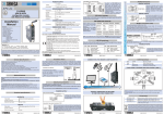
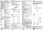
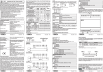
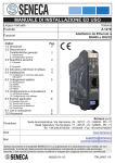
1
EN
Strain Gauge Converter
General Description
Module Z-SG is a strain gauge signal converter. Measurements taken using the 6-wires
or 4-wires technique are available through Modbus-RTU serial protocol or the analog
output. The module is also characterised by:
Facilitated power supply and serial bus wiring by means of the bus housed in the DIN
rail.
Communication configurability by DIP-switch or software.
RS485 serial communication with MODBUS RTU protocol, maximum 32 nodes.
Protection against ESD discharge up to 4 kV.
Input insulation: 1500 Vac compared to all the other circuits.
Insulation between communication and power supply: 1500 Vac.
Insulation between analog output and power supply: 1500 Vac.
Analog output in voltage or current, with settable limits.
Strain gauge calibration with standard weight.
Strain gauge calibration not required if the sensitivity of the strain gauge is known.
Configurable digital I/O.
Rejection at 50 and 60Hz.
Configurable Resolution.
Sampling frequency settable from 12,53 Hz to 151,71 Hz.
Stable weight indication via Modbus register/digital output.
Remote writing of the tare in volatile and/or non-volatile memory by digital
input/Modbus register/Modbus commands.
Strain gauge directly powered by instrument.
Ratiometric measurement.
Sensitivity from "1 to "64 mV/V, settable by DIP-switch for integer values, via software
for real/integer values.
Alarm generated when programmable threshold is exceeded.
Measurement stabilisation through the calculation of the moving average value of a
programmable number of samplings.
Complete configurability by Z-NET3 software.
Technical Specifications
Power supply :
Consumption :
10..40 Vdc or 19..28 Vac (50..60 Hz)
max 2.0 W
Communication Ports :
-RS485, 2400..115200 Baud.
-RS232, 2400 Baud, Address: 01, Parity: NO, Data: 8
bits, Stop bits: 1.
MODBUS-RTU
Protocol :
Analog Input
Input Type :
Full scale :
Error :
Insulation :
6-wires or 4-wires differential measurement input.
" 5 mV .. " 320 mV
Calibration : 0,01 % of the full scale value.
Linearity : 0,01 % of the full scale value.
Thermal Stability : 0,0025 % / °C of the full scale value.
1500 Vac respect to the remaining circuits.
MI001204-E
Strain gauge characteristics
Power supply voltage :
Minimum impedance :
Sensitivity :
Terminals :
Analog Output
Output Voltage :
Output Current :
Transmission error :
Response time (10%..90%) :
5 Vdc
87 W equivalent (derived from several strain gauges
connected in parallel).
From "1 mV/ V to "64 mV/V.
4 or 6.
0..10 Vdc, 0..5 Vdc, minimum load resistance : 2 kW.
0..20 mA, 4..20 mA, maximum load resistance : 500 W.
0,1 % (max. range).
5 ms.
Protection :
Environmental conditions :
Storage temperature :
Signalling by LED :
Connections :
Box :
Dimensions and weight :
Reference standards :
24 bit.
25 ppm/K.
settable from 12,53 Hz to 151,71 Hz.
settable at either 50 Hz or 60 Hz.
1500 Vac between the measurement input and all the
other circuits.
1500 Vac between power supply and communication.
1500 Vac between power supply and analog output.
IP20
Temperature -10..+65 °C.
Humidity 30..90 % non-condensing.
Altitude: up to 2000 m a.s.l.
-20..+85 °C
Power supply, calibration, RS485 communication.
-Removable 3-way screw terminals, 5,08 mm pitch.
-Rear IDC10 connector for DIN rail.
-3.5 mm stereophonic front jack for RS232 (COM)
connection.
-Lateral button for strain gauge calibration.
PBT, black
100 x 112 x 17,5 mm, 140 g.
EN61000-6-4/2002 (electromagnetic emission,
industrial environment)
EN61000-6-2/2005 (electromagnetic immunity,
industrial environment)
EN61010-1/2001 (safety).
All circuits must be insulated from the other circuits
under dangerous voltage with double insulation. The
power supply transformer must comply with
EN60742: “Insulated transformers and safety
transformers”.
MI001204-E
ENGLISH - 2/16
Calibration
Button
ERR PWR
SW1
SW2
RX
2
3
10 ÷ 40 VDC
19 ÷ 28 VAC
TX
COM
S
Z-SG
SW3
7 8 9
10 11 12
To use the lateral button for calibration, move to
OFF position the DIP-switch 1 of SW2.
DESCRIPTION OF OPERATION
MI001204-E
2.0 W
Power Supply AC-
RS485 A
RS485 B
IDC10
There is no insulation between RS485 and the analog output.
RS232 SERIAL PORT
Connection cable DB9 with a 3.5 mm stereo Jack, can be assembled as indicated in the
following figure, or can be bought as an accessory.
DB9-F
9
5
6
1
GND
Tx
3.5 mm Stereo Jack
Rx
GND Tx
ANALOGUE INPUT
Rx
The figure below shows the connections to be made for connection to a strain gauge.
The terminals have the following meaning:
6 wires measurement
+ Sense
- Signal 12
- Sense
11
10
+ Excitation
7
8
9 + Signal
ENGLISH - 3/16
- Signal 12
Stable Weight Function
ANALOG OUTPUT
The module provides an analog output in voltage (0..10 VDC, 0..5 VDC) or current (0..20
mA, 4..20 mA). We recommend using shielded cables for the electric connections above.
Analog Output
The analog output permits the retransmission of the net weight as follows:
-If the Net Weight in units of weight # MINOUT, the output relays 0%.
- If the Net Weight in units of weight $ MAXOUT, the output relays 100%.
-At intermediate values, the progression is linear.
Where MINOUT and MAXOUT in Mode 1 and 2 may be set via MODBUS (The default
values are respectively: 0,00 and 10000,00).
Rejection at 50 and 60 Hz
Rejection to interference at both 60 and 50 Hz can be enabled at the same time.
See Appendix A for details on setting and optimisation.
+
5
Digital input/output
The instrument offers the possibility to select either a digital input or a digital output. This
selection (input or output) is made only by DIP-switch.
Digital Input: allows to memorize the tare during all the calibration phases and may be
used as an alternative to the lateral button.
On the normal functioning it may be used to acquire the temporary tare, which will be lost at
the turn off of the module; at the next start up the tare value, acquired on calibration, will be
loaded.
Digital Output: the output can be configured via Modbus for three different operating
modes and switches to ON or OFF status (always according to Modbus setting) whenever:
1)The Gross Weight exceeds the Full Scale of the strain gauge (Default Setting).
2)The Weight is stable and the Net Weight exceeds the threshold set.
3)The Weight is stable.
V
Current
Output
4
+
A
5
There is no insulation between RS485 and the analog output.
DIGITAL INPUT/OUTPUT
1
+
+
V
24 Vdc
PROGRAMMING
24 Vdc
6
1
PWR LED (GREEN) Meaning
Power supply is present.
ERR LED (YELLOW) Meaning
Calculation of Measurement Moving Average
Steady/Flashing
Signallings relative to the calibration phases. For further
informations see the Calibration Addendum, containing the
calibration procedures.
Installation rules
RX LED (RED)
Meaning
Data are being received through the RS485 communication port.
The moving average of a settable number of samples (NR_SAMPLINGS: 1 ..100) can be
calculated. In this way, the Net Weight displayed is the calculated moving average value.
For Mode 1 and 2, NR_SAMPLINGS may be set via MODBUS (default: 100).
The module is designed to be installed in vertical position on a DIN 46277 rail. In order to
ensure optimum performance and the longest working life, the module(s) must be
supplied adequate ventilation and no raceways or other objects that obstruct the
ventilation slots. Never install modules above sources of heat; we recommend installation
in the lower part of the control panel.
Steady
TX LED (RED)
Steady
STRAIN GAUGE SENSITIVITY
SW2 6 7 8
± 1 mV/V
± 2 mV/V
± 4 mV/V
± 8 mV/V
± 16 mV/V
± 32 mV/V
± 64 mV/V
Sensitivity from MODBUS register SENSE_RATIO (40044).
Real values (not only integer) may be set too.
Load
INDICATIONS BY LED ON THE FRONTAL PANEL
Steady
The release of Z-NET3 software to be used for product’s programming/configuration, must
be the 1.0.2883 or later. This software may be downloaded from the web site
www.seneca.it.
During initial programming, the EEPROM (SW3 ..8 in OFF position) default setting values
originally programmed as follows can be used:
Address = 1, SPEED = 38400 baud, PARITY = none, BIT NUMBER = 8, STOP BIT = 1.
The module can also be programmed through the front connector (COM) while paying
attention to set the following connection parameters:
Address = 1, Speed = 2400 Baud, PARITY = none, STOP BIT = 1.
The Com communication port behaves in the same way as the RS485 bus port except for
the communication parameters described above. It also has priority over the RS485 serial
port and closes after 10 seconds of inactivity.
Meaning
Data are being transmitted through the RS485 communication port.
Electric connections
RS485 SERIAL PORT AND POWER SUPPLY
SERIAL INTERFACE
The electric connections for power supply can be made by using either the terminals or the
bus for the Seneca DIN rail. The RS485 bus connections are available only by using the
bus for the DIN rail.
For detailed information on RS485 serial interface, consult the documentation provided by
the website www.seneca.it, in the section Prodotti/Serie Z-PC/MODBUS TUTORIAL.
MI001204-E
MI001204-E
ENGLISH - 4/16
ENGLISH - 7/16
Digital Output
Digital Input
V
MI001204-E
RS485 TERMINATOR
SW3 1 2
x Terminator OFF, the SW3-2 is not used.
x Terminator ON, the SW3-2 is not used.
The module can be set to provide either a digital input or digital output.
The connections in the two cases are as follows:
6
UTILIZE / CALIBRATION MODE (**)
SW2 4 5
Modes 2 and 4 are selected.
Modes 1 and 3 are selected.
The tare value acquired by the lateral button or digital input is saved on
non-volatile memory (for Modes 2 and 4).
Manual calibration of the strain gauge (for Modes 1 and 3).
ENGLISH - 5/16
The Stable Weight function informs the user of the precise moment in which weight has
stabilised.
This information is available via Modbus register (see the Modbus Registers section,
Register 40066: STATUS) and can also be signalled by digital output (after previous
selection and programming by Modbus). This function is characterised by the two
parameters: DWeight and DTime. The weight is considered stable whenever the net
weight in the DTime has changed by a quantity lower than DWeight.
4
0..10 V
0..5 V
0..20 mA
4..20 mA
(**) For further informations consult the Calibration Addendum, containing the
calibration procedures.
- Excitation
MI001204-E
Voltage
Output
Communication Parameters from EEPROM (*)
Fixed Address: 01
Fixed Address: 02
Fixed Address: 03
Fixed Address: 04
X X X X X X Fixed Address, as from binary representation.
Fixed Address: 63
(*) The default configuration is the following: Address 1, 38400, no parity, 1 stop bit.
11
10
- Excitation
ADDRESS
SW1 3 4 5 6 7 8
OUTPUT
SW2 2 3
4 wires measurement
+ Excitation
7
8
DIP-SWITCH SETTING
The settings of the DIP-switches define the module's communication parameters
(address and speed) and other parameters we are going to explain. In order for the setting
modifications made to be confirmed valid, the module must be switched off and on again.
In all the following tables, the indication
corresponds to a DIP-switch set in ON; no
indication is provided when the DIP-switch is set in OFF.
COMMUNICATION SPEED (BAUDRATE)
SW1 1 2
9600 Baud
19200 Baud
38400 Baud
57600 Baud
DIGITAL I/O SELECTION - ENABLING LATERAL BUTTON OF CALIBRATION
SW2 1
Digital Input. Besides it enables the lateral button of calibration (**).
Digital Output
7: Strain gauge positive power supply
8: Strain gauge positive power supply reading
9: Strain gauge positive reading
10: Strain gauge negative power supply
11: Strain gauge negative power supply reading
12: Strain gauge negative reading
The use of shield cables is necessary for the electronic connections.
9 + Signal
The strain gauge's measured value is translated into an analog output signal (current or
voltage). The measurement of the input is available through Modbus RTU protocol upon
query by RS485 bus and/or RS232 jack.
Serial communication parameter settings can be made either by Modbus RTU or DIPswitch, whereas the settings selectable via SW2 cannot be configured via Modbus (except
the sensitivity).
The instrument's various functions are described below.
Power Supply AC+
RS485 GND
1
DIP-switch Position
Lateral button for calibration
1 2 3
4 5 6
ENGLISH - 1/16
Digital Input or Output (as alternative)
Max Voltage : 30 V.
Optoisolated digital Input :
Max Current : 50 mA, Max Voltage : 30 V.
Optoisolated digital Output :
Other Features
ADC :
Thermal drift :
Sampling frequency :
Interference rejection :
Insulation voltage :
The calibration procedures are illustrated in detail on the appropriate attached addendum.
Anyway they are briefly listed below.
Calibration Mode 1
The user has at his disposal a PC with Z-NET3 software (release 1.02883 or later, to
download from www.seneca.it web site) and a weight of known value. It is not necessary
that the known weight is equal to the full scale of the strain gauge or to the full scale of the
measurement.
Calibration Mode 2
The user has at his disposal a PC with Z-NET3 software and a strain gauge with declared
sensitivity.
Calibration Mode 3
The user does not have at his disposal a PC but has a weight of known value equal to the
full scale of measurement.
Calibration Mode 4
The user does not have at his disposal a PC and a weight of known value but has only a
strain gauge with declared sensitivity.
Frontal Panel and Leds
Bus connector for DIN rail
Power Supply from terminals
MODULE Z-SG CALIBRATION
Z-SG
ENGLISH - 6/16
R
THE INTERNATIONAL CERTIFICATION NETWORK
ISO9001-2000
SENECA s.r.l.
Via Germania, 34 - 35127 - Z.I. CAMIN - PADOVA - ITALY
Tel. +39.049.8705355 - 8705359 - Fax +39.049.8706287
e-mail: [email protected] - www.seneca.it
MI001204-E
ENGLISH - 8/16
MODBUS REGISTERS
Z-SG has MODBUS 16 bits (words) registers, accessible by RS485 or RS232 serial
communication. In the next paragraphs, we shall describe the supported MODBUS
commands, and the functions of the registers.
Supported MODBUS Commands
Code
03 (*)
04 (*)
06
16
Function
Read Holding Registers
Read Input Registers
Write Single Register
Write Multiple Registers
Description
Reading of word registers up to 16 at a time.
Reading of word registers up to 16 at a time.
Writing of a word register.
Writing of word registers up to 16 at a time.
(*) The two functions have the same effect.
KNOWN
WEIGHT_FL_L
MAXOUT_FL_H
Bit [15:8]
HOLDING REGISTER
The 16-bit Holding Registers have the following structure:
Most
Least
Bit Index
Significant bit
Significant bit
MAXOUT_FL_L
15 14 13 12 11 10 9 8 7 6 5 4 3 2 1 0
Word (16 bits): MODBUS Register
The Bit notation [x:y] shown in the table indicates all the bits from x to y. For example, Bit
[2:1] indicates bit 2 and bit 1, and illustrates the meaning of the various linked
combinations of the values of the two bits. Remember that the MODBUS 3, 4, 6 and 16
single and multiple reading and writing functions can be executed on the following
registers.
The following indication (only readable or also writable) is provided for every register:
R: Readable
W: Writeable
REGISTER
MACHINE ID
Description
ADD. R/W
Bit [15:8]: contain the module's ID: 23 40001 R
(hexadecimal: 0x17).
Bit [7:0]: contain the firmware's revision.
FW_CODE
Register that contains the firmware's internal 40002
code.
R
HW_REL
Register that contains the instrument's 40003
hardware version.
R
ADDR
Register for the setting of the module's 40004 R/W
address and parity control.
Set the module's address. Permissible values
from 0x00 to OxFF (decimal values in the range of
0-255 ). Default address: 1.
Bit [15:8]
MI001204-E
Set the type of parity control:
00000000 : No parity
( NONE ) (Default)
00000001 : Even parity ( EVEN )
00000010 : Odd parity ( ODD )
Register for the setting of the Baudrate and 40005 R/W
BAUDR
the response delay time in characters.
Set the serial communication speed value
Bit [15:8]
(Baudrate) :
00000000 (0x00) : 4800 Baud.
00000001 (0x01) : 9600 Baud.
00000010 (0x02) : 19200 Baud.
00000011 (0x03) : 38400 Baud (Default).
00000100 (0x04) : 57600 Baud.
00000101 (0x05) : 115200 Baud .
00000110 (0x06) : Not permitted.
00000111 (0x07) : 2400 Baud.
Bit [7:0]
Set the response delay time in characters that
represents the number of pauses of 6 characters
each to be entered between the end of the Rx
message and the start of the Tx message.
Default value: 0.
SENSE RATIO _FL_H Sensitivity of the strain gauge in mV/V 40044 R/W
(floating point format, most significant word).
If the DIP-switches: SW2-7/8/9 are all in ON
Bit [15:8]
position, the sensitivity of the strain gauge in mV/V
is set by this register (floating point format, most
significant word).
SENSE RATIO _FL_L Sensitivity of the strain gauge in mV/V 40045 R/W
(floating point format, least significant word).
Bit [15:8]
FULL SCALE _FL_L
KNOWN
WEIGHT_FL_H
Bit [15:8]
Full scale of the strain gauge in technical 40046 R/W
units (floating point format, most significant
word).
If the full scale of the strain gauge is declared
(Mode 2: with both SW2-4/5 in OFF position), sets
the full scale of the strain gauge in technical units
of weight (kg, pounds, etc).
Floating point Format, most significant word.
Default: 10000,00.
Full scale of the strain gauge in technical 40047 R/W
units (floating point format, least significant
word).
Known weight of the strain gauge in technical 40048 R/W
units (floating point format, most significant
word).
If the full scale of the strain gauge is not declared
MI001204-E
Bit [15:8]
MINOUT_FL_L
THRES_FLOAT_H
Bit [15:0]
THRES_FLOAT_L
ENGLISH - 9/16
Bit [7:0]
FULL SCALE _FL_H
MINOUT_FL_H
ENGLISH - 10/16
(Mode 1: SW2-4=OFF and SW2-5=ON), it sets
the known weight of the strain gauge in technical
units of weight (kg, pounds, etc).
Floating point format, most significant word.
Default: 10000,00
Known weight of the strain gauge in technical 40049 R/W
units of weight (floating point format, least
significant word).
Value of the net weight in technical units of 40050 R/W
weight which corresponds to the maximum
value of the analog output (floating point
format, most significant word).
Value of the net weight in technical units of weight
which corresponds to the maximum value of the
analog output (100%). The value is in floating
point format (most significant word) and so it has
to be referred to the net weight in floating point
format. Default: 10000,00.
Value of the net weight in technical units of 40051 R/W
weight which corresponds to the maximum
value of the analog output (floating point
format, least significant word).
Value of the net weight in technical units of 40052 R/W
weight which corresponds to the minimum
value of the analog output (floating point
format, most significant word).
Value of the net weight in technical units which
corresponds to the minimum value of the analog
output (0%). The value is in floating point format
(most significant word) and so referred to the net
weight in floating point format. Default: 0,00.
Value of the net weight in technical units of 40053 R/W
weight which corresponds to the minimum
value of the analog output (floating point
format, least significant word).
Threshold in unit of weight (floating point 40054 R/W
format, most significant word).
If the net weight (WEIGHT_FLOAT: 40064-65)
exceeds the threshold value set and the weight is
stable, the digital output (whenever set in the
second operating mode) is closed or opened.
Default: 0,00.
Threshold in unit of weight (floating point 40055 R/W
format, least significant word).
MI001204-E
DWEIGHT_FLOAT_H
Bit [15:0]
DWEIGHT_FLOAT_L
DTIME
Bit [15:0]
RESOLUTION/
DIGITAL_OUT_TYPE
Bit 15
Bit [14:8]
Bit 7
Bit [6:0]
Bit [15:0]
WEIGHT_SHORT
WEIGHT_FLOAT_H
WEIGHT_FLOAT_L
ENGLISH - 11/16
Weight variation in technical units accepted 40056 R/W
for stable weight (floating point format, most
significant word).
With the Register 40058 (DTime), it permits to
establish when the weight is stable. This
represents the variation in units of weight
accepted for stable weight. Weight is considered
stable whenever the net weight
(WEIGHT_FLOAT: 40064-65) in the DTime has
changed by a quantity < than DWeight. Default: 1.
Weight variation in technical units accepted 40057 R/W
for stable weight (floating point format, least
significant word).
Time in units of 100 ms used to establish 40058 R/W
whether or not the weight is stable.
With the registers 40056-57 (DWeight) establishes
whether or not the weight is stable, and is
expressed in units of 100 ms. Weight is
considered stable whenever the net weight
(WEIGHT_FLOAT: 40064-65) in the DTime has
changed by a quantity < than DWeight.
Default Value: 1 (100 ms).
Sets the resolution and the shifting of the 40059 R/W
digital output (if selected by DIP-switch).
0: Resolution set by bit [14:8]
1: 24 bit Resolution
If Bit 15 = 0 it sets the resolution value multiplied by
1000. Default: 30000 monopolar points.
Defines the shifting of the output upon the
appearance of the condition set by the Bit[6:0]:
0 : The output is normally opened and closes
whenever the condition selected arises (default).
1 : The output is normally closed and opens
whenever the condition selected arises.
Defines the operation of the digital output and
switches to ON or OFF (according to the status of
Bit 7) when any of the following conditions arise:
0: The Gross Weight exceeds the Full Scale
(Default setting).
1: The Weight is stable and the Net Weight
exceeds the threshold set.
2: The Weight is stable.
Net Weight=WEIGHT_FLOAT (40064-65).
MI001204-E
Configuration register for setting of rejection 40060 R/W
and sampling frequency.
The value of this register sets the sampling
frequency and the characteristics interference
rejection. Appendix A provides the values of
these parameters according to the value set in this
r e g i s t e r. D e f a u l t v a l u e : 8 2 ( 0 x 0 0 5 2 ) ,
corresponding to the Sampling Frequency: 49,95
Hz, Rejection at 50 Hz and 60 Hz: Enabled.
NRSAMPLINGS_TARE Sets the number of samplings of the ADC 40061 R/W
upon which the moving average will be
calculated and indicates the tare value used.
Bit [15:9]
Not used
Bit 8
Used Tare value (only for Modes 2 and 4):
0: the value of the tare had not never been written
on the memory: at the start up the factory value
will be loaded.
1: the value of the tare had been written at least
once on the memory: at the start the last set value
will be loaded.
Bit [7:0]
The number of samplings upon which the moving
average must be calculated. The
WEIGHT_FLOAT Register provides the mean
value calculated. Permissible values: 1..100.
Default: 100.
40062 R
Filtered ADC value.
ADC_VAL
CONFIG FREQ_REJ
ENGLISH - 12/16
Net weight value in ±30000 scale.
40063
Net weight value in ± 30000 scale.
Equal to 0: if the WEIGHT_FLOAT (40064-65) is
equal to MINOUT_FL (40052-53, value of the
weight corresponding to the minimum value of
the analog output).
Equal to 30000: if the WEIGHT_FLOAT is equal
to MAXOUT_FL (40050-51, value of the weight
corrisponding to the maximum value of the
analog output).
Values<0 if WEIGHT_FLOAT<MINOUT_FL.
Limited: -31000..+31000.
Register containing the net weight value in 40064
technical units of weight (floating point
format, most significant word).
Register containing the net weight value in 40065
technical units of weight (floating point
format, least significant word).
MI001204-E
R
Remote Memorizing of the Tare
The memorizing of the tare may be perfomed in the following ways:
Memorizing Memorizing
Action
in Nonin Volatile
Volatile
Memory
Memory
Digital Input
with
ON
Digital Input
with
ON
Digital Input
with
ON
Bit in reg. STATUS
or
with
Command 49594
Bit in reg. STATUS
or
with
Command 49594
ON
ON
Command: 49914 with
ON
Command: 49914 with
ON
4
5
4
5
4
5
4
5
4
5
4
5
4
5
Notes
Only for Modes 2 or 4. Once the
tare has been saved, restart the
module in these modes.
-
APPENDIX A
Configuration of Sampling Frequency, Rejection.
The table below provides the values that can be set in the Modbus register CONFIG
FREQ_REJ (40060) together with the corresponding sampling frequency values. It is also
indicating whether rejections are enabled at 50 or 60 Hz.
R
R
Value of Register:
CONFIG FREQ_REJ
(40060)
27
55
82
109
155
183
210
237
ENGLISH - 13/16
Sampling
Freq. (Hz)
Rejection: Rejection:
50 Hz
60 Hz
151,71
74,46
49,95
37,59
50,57
24,82
16,65
12,53
MI001204-E
NO
NO
YES
NO
NO
YES
YES
NO
NO
NO
YES
YES
NO
NO
YES
YES
ENGLISH - 15/16
STATUS
Bit [15:5]
Bit 4
Status Register
40066 R/W
Not used.
Stable weight
1: signals that the weight is stable.
Bit 3
Memorizing of the tare on volatile memory:
1 : a memorizing of the tare is required (the value
is valid up to the next start up of the module).
Gross Weight # Memorized Tare:
Bit 2
1: signals that the gross weight is # Tare value
saved in memory.
Gross Weight $Max Full Scale of the strain gauge:
Bit 1
1 : signals that the gross weight is $ Maximum
allowed Full Scale.
Alarm Status:
Bit 0
1: It signals that the net weight value has
exceeded the threshold and that the weight is
stable.
STATUS_DIP-SWITCH Status of the Dip-switches.
40067 R
Bit 15
Indicates the status of DIP1-SW1.
Bit 14
Indicates the status of DIP2-SW1.
Bit 13
Indicates the status of DIP3-SW1.
Bit 12
Indicates the status of DIP4-SW1.
Bit 11
Indicates the status of DIP5-SW1.
Bit 10
Indicates the status of DIP6-SW1.
Bit 9
Indicates the status of DIP7-SW1.
Bit 8
Indicates the status of DIP8-SW1.
Bit 7
Indicates the status of DIP1-SW2.
Bit 6
Indicates the status of DIP2-SW2.
Bit 5
Indicates the status of DIP3-SW2.
Bit 4
Indicates the status of DIP4-SW2.
Bit 3
Indicates the status of DIP5-SW2.
Bit 2
Indicates the status of DIP6-SW2.
Bit 1
Indicates the status of DIP7-SW2.
Bit 0
Indicates the status of DIP8-SW2.
40068 R/W
Commands Register.
COMMAND
Bit [15:0]
By inserting the next codes the following actions
are performed:
43948 (0xABAC): Module reset.
49594 (0xC1BA): Save the tare in volatile
memory.
49914 (0xC2FA): Save the tare in volatile and
non- volatile memory.
50700 (0xC60C): Save the known weight in nonvolatile memory.
MI001204-E
ENGLISH - 14/16
Disposal of Electrical & Electronic Equipment (Applicable throughout the European Union and
other European countries with separate collection programs)
This symbol, found on your product or on its packaging, indicates that this product should not be
treated as household waste when you wish to dispose of it. Instead, it should be handed over to an
applicable collection point for the recycling of electrical and electronic equipment. By ensuring this
product is disposed of correctly, you will help prevent potential negative consequences to the
environment and human health, which could otherwise be caused by inappropriate disposal of this
product. The recycling of materials will help to conserve natural resources. For more detailed
information about the recycling of this product, please contact your local city office, waste disposal
service or thè retail store where you purchased this product.
This document is property of SENECA srl. Duplication and reprodution are forbidden, if not authorized. Contents
of the present documentation refers to products and technologies described in it.All technical data contained in the
document may be modified without prior notice Content of this documentation is subject to periodical revision.
R
THE INTERNATIONAL CERTIFICATION NETWORK
ISO9001-2000
SENECA s.r.l.
Via Germania, 34 - 35127 - Z.I. CAMIN - PADOVA - ITALY
Tel. +39.049.8705355 - 8705359 - Fax +39.049.8706287
e-mail: [email protected] - www.seneca.it
MI001204-E
ENGLISH - 16/16